

Page 1

Trimble LOADRITE E2750
refuse truck scales
Software 60453
Version 2.0
Revision A
Mar ch 2017
ENGLISH
USER MANUAL
Page 2

Page 3

1-1
LOADRITE E2750 User Manual
LOADRITE E2750 User manual
Software Number: 60453
Version Number: 2.0
Document Number: 110969-95-ENG
Revision: A
Issued Date: March 2017
E: info@loadritescales.com
W: www.loadritescales.com
© 2017 Trimble Inc. All rights reserved. Trimble, the Globe & Triangle logo are trademarks and/or registered trademarks of Trimble Inc, registered in the United
States and in other countries. Loadrite is a trademark and/or registered trademark of Trimble Inc. All other trademarks and registrations are the property of their
respective owners.
The software contains proprietary information of Trimble Inc; it is provided under a license agreement containing restrictions on use and disclosure and is also
protected by copyright law. Reverse engineering of the software is prohibited.
This document is copyrighted with all rights reserved. Under copyright laws, this document may not be copied in whole or in part, reproduced in any other media,
stored in a retrieval system, or transmitted in any form or by any means, electronic, mechanical, photocopying, recording or otherwise, without the express written
permission of Trimble Inc. Permitted copies must carry the same proprietary and copyright notices as were affixed to the original. Under the law, copying includes
translation into another language.
Published in New Zealand.
Page 4

1-2
LOADRITE E2750 User Manual
IMPORTANT SAFETY INFORMATION
PLEASE READ CAREFULLY BEFORE USING THE LOADRITE™ WEIGHING SYSTEM
This is the safety alert symbol. It is used to alert you to potential personal injury hazards.
Obey all safety messages that follow this symbol to avoid possible injury or death.
WARNING indicates a potentially hazardous situation which, if not avoided, could result in
death or serious injury.
CAUTION indicates a potentially hazardous situation which, if not avoided, may result in
minor or moderate injury.
CAUTION used without the safety alert symbol indicates a potentially hazardous situation
which, if not avoided, may result in property damage.
It is your sole responsibility to place, secure and use the LOADRITE Weighing System in a manner that will not cause accidents,
personal injury or property damage. Always observe safe operating practices.
Do not install the LOADRITE Weighing System in a way that may interfere with the safe operation of the vehicle, or deployment
of safety equipment.
Before you use the LOADRITE Weighing System for the first time, familiarize yourself with the system and its operation.
Do not handle the LOADRITE Weighing System if it is hot. Let the product cool, out of direct sunlight.
Ensure that the LOADRITE Weighing System is connected to a power source with the correct fitting and voltage requirements.
Do not attempt to service the LOADRITE Weighing System as this could result in personal injury.
Removing LOADRITE Weighing System equipment or adding accessories could affect the accuracy of weighing data and
your warranty.
Failure to adhere to these warnings and cautions may lead to death, serious injury or property damage.
Trimble Inc disclaims all liability for installation or use of the LOADRITE Weighing System that causes
or contributes to death, injury or property damage, or that violates any law.
Page 5

1-3
LOADRITE E2750 User Manual
TABLE OF CONTENTS
1. LOADRITE E2750 WEIGHING SYSTEM ..................................................................................... 1-5
1.1. Weight Measurement ...................................................................................................... 1-5
1.2. Display ................................................................................................ ............................ 1-5
1.3. Keypad ........................................................................................................................... 1-6
1.4. Trigger ................................................................................................ ............................ 1-7
1.5. Turning On ...................................................................................................................... 1-7
2. WEIGHING ................................................................................................................................... 2-8
2.1. Weighing a Load (Front Lift and Rear Lift) ...................................................................... 2-8
2.2. Weighing a Load (Hook Lift)............................................................................................ 2-9
2.3. Recalling Last Bin Weight ............................................................................................. 2-10
2.4. Entering Bin Sizes ........................................................................................................ 2-10
3. TOTAL ................................ ................................ ................................ ................................ ....... 3-11
3.1. To clear the Total .......................................................................................................... 3-11
3.2. Long Total..................................................................................................................... 3-11
4. ZEROING THE E2750 ................................................................................................................ 4-12
4.1. To zero the E2750 (Front lift and Rear lift) .................................................................... 4-12
4.2. To zero the E2750 (hook lift) ......................................................................................... 4-12
4.3. Large Zero Error ........................................................................................................... 4-12
5. ADDITIONAL DATA .................................................................................................................. 5-13
5.1. To enter additional data ................................................................................................ 5-13
6. USER MENU OPTIONS ............................................................................................................. 6-14
6.1. Using the User Menu .................................................................................................... 6-14
6.2. Setting the Time and Date ............................................................................................ 6-14
7. PRINT FUNCTIONS ................................................................................................................... 7-15
7.1. Receipt printing ................................ ................................ ............................................. 7-15
8. APPENDIX A: SPAN CALIBRATION CORRECTION ............................................................... 8-16
8.1. To correct the calibration of the E2750 ......................................................................... 8-16
8.2. Checking the adjustment .............................................................................................. 8-17
9. APPENDIX B: ERROR MESSAGES ......................................................................................... 9-18
9.1. Contact LOADRITE ...................................................................................................... 9-18
9.2. Contact LOADRITE 1010 .............................................................................................. 9-18
9.3. Demo Mode! ................................................................................................................. 9-18
9.4. Limp Mode! ................................................................................................................... 9-18
9.5. Low Power .................................................................................................................... 9-18
9.6. No Dump. Add? ............................................................................................................ 9-18
9.7. Over R1 / Over R2 ........................................................................................................ 9-18
9.8. Tilt Fault ........................................................................................................................ 9-18
9.9. Trigger Fault ................................................................................................................. 9-18
10. APPENDIX C: SPECIFICATIONS............................................................................................ 10-19
10.1. Minimal Weighing Delay ............................................................................................. 10-19
10.2. Power Requirements .................................................................................................. 10-19
10.3. Signal Inputs and Outputs ........................................................................................... 10-19
Page 6

1-4
LOADRITE E2750 User Manual
10.4. Display / Keyboard ...................................................................................................... 10-19
10.5. Clock .......................................................................................................................... 10-19
10.6. Physical ...................................................................................................................... 10-19
10.7. Optional features ........................................................................................................ 10-19
10.8. Output/Input Connections ........................................................................................... 10-20
11. APPENDIX D: LEGAL INFORMATION ................................................................................... 11-22
Page 7
1-5
LOADRITE E2750 User Manual
1. LOADRITE E2750 WEIGHING SYSTEM
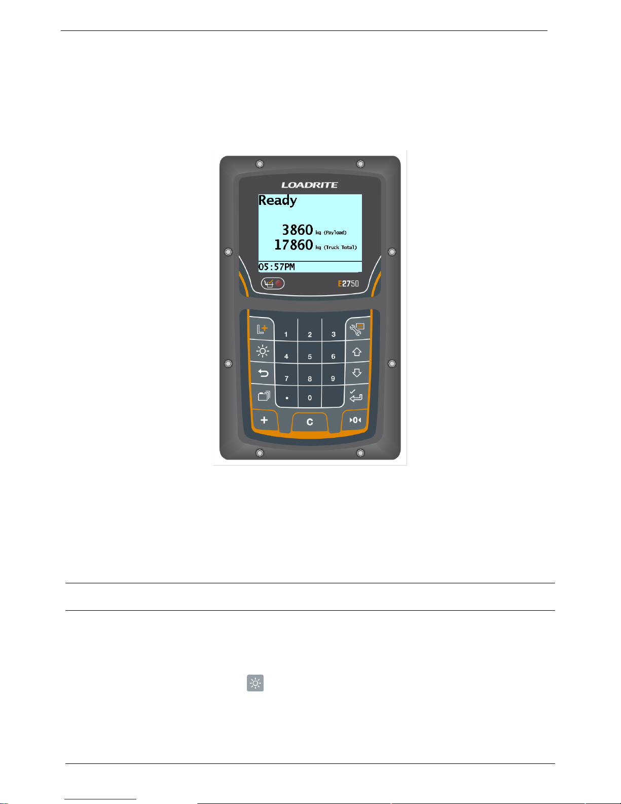
The LOADRITE E2750 weighing system measures the weight of loads lifted by refuse trucks.
The heart of the system is the E2750 Indicator, which provides a keypad for entering instructions and an LCD screen to display
weights and messages.
The Indicator has internal memory which stores settings and data even when switched off.
The E2750 is installed in the cab of the truck and is connected to sensors on the lifting arms.
1.1. WEIGHT MEASUREMENT
The E2750 Indicator measures the sensors as the bin is raised and lowered. The Indicator converts the sensor signals into a
weight reading and displays the value.
An electronic position sensor mounted on the lift arms ensures that the weight measurements are taken at the same position
each time.
The weight of the lifting arms are zeroed out when the system is calibrated. In addition, on most truck styles the bin is weighed
on the way up (full), and then again as it is lowered (empty). These two weights are subtracted from each other, so that only the
weight of the contents (bin payload) is displayed. The bin payload is then added to the truck total.
NOTE: On some truck types, only total bin and contents weight are measured, for example, Hook Lift trucks. In this case, there
may be no position sensor. Refer to section 2.2 (page 2-9) for more details.
1.2. DISPLAY
The E2750 display gives instructions and information, along with the measured or total truck weight.
The display is backlit for ease of operation in low light conditions.
To adjust the display backlight level, press .
Page 8
1-6
LOADRITE E2750 User Manual
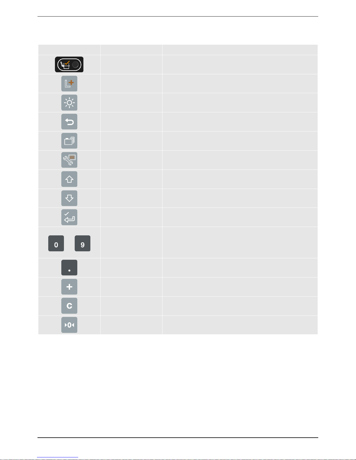
1.3. KEYPAD
Icon
Name
Description
Trigger Light
Illuminates when a load is lifted past the past the trigger point. When
this light is on, the load may be ‘added’ to the Total.
Long Total
Displays the Long Total screen.
Backlight
Adjusts the screen and keypad backlight.
Recall
Recalls the last bin weight.
Data menu
Displays the Data Menu.
User menu
Back
Displays the User Menu.
Moves back one menu screen.
Up
Moves up a list of options.
Down
Moves down a list of options.
Enter
Selects an item.
Accepts changes.
-
Numeral keypad
Used to select the bin size or enter numbers 0 - 9.
Decimal Point
Print receipt
Used to enter a decimal point.
Used to print a receipt as required.
Add
Adds the current bin contents to the total.
Clear
Clears the truck total.
Zero
Zeroes the empty arms.
Page 9

1-7
LOADRITE E2750 User Manual
1.4. TRIGGER
To ensure consistent and accurate measurement, the E2750 system incorporates a position sensor which initiates the weight
measurement as the lifting arms are raised and lowered. One of the two below options may be fitted to your truck:
LR908 Rotary ‘Trigger’
LR970 Angle Sensor
NOTE: Some truck types (for example, Hooklift) may not have a position sensor, and other styles of trucks may use proximity
switches or other devices.
1.5. TURNING ON
The E2750 is normally connected so that it turns on with the ignition of the truck.
When turned on, the display shows a sequence of check messages, followed by the Ready message.
Page 10
2-8
LOADRITE E2750 User Manual
2. WEIGHING
When ready to weigh, the E2750 displays Ready on the display. If the arms are not in the correct position to start the weighing
cycle, the display will show the message Lower Arms.
There may be other information on the display, depending on the mode of operation.
The total truck payload weight is also shown.
2.1. WEIGHING A LOAD (FRONT LIFT AND REAR LIFT)
2.1.1. Weighing essentials
For Front Lift Trucks:
Make sure the bin is fully on the forks and hard back on the buffers.
Try to keep the bin level as it is lifted, until weighing is complete (normally about the top of the windscreen).
Try to keep the bin moving at a steady speed while weighing.
Empty the bin as normal.
Try to keep the bin level while lowering during weighing.
For Rear Lift Trucks:
Ensure the bin is fully on the lifter ‘comb’.
Lift smoothly from the ground; don’t stop while weighing.
Empty the bin as normal.
Lower the bin smoothly; don’t stop as the bin is weighed while lowering.
2.1.2. To weigh a load
This section describes the general weighing process for Front Lift, Rear Lift and Side Lift trucks. (i.e. those trucks that empty the
bin into a hopper).
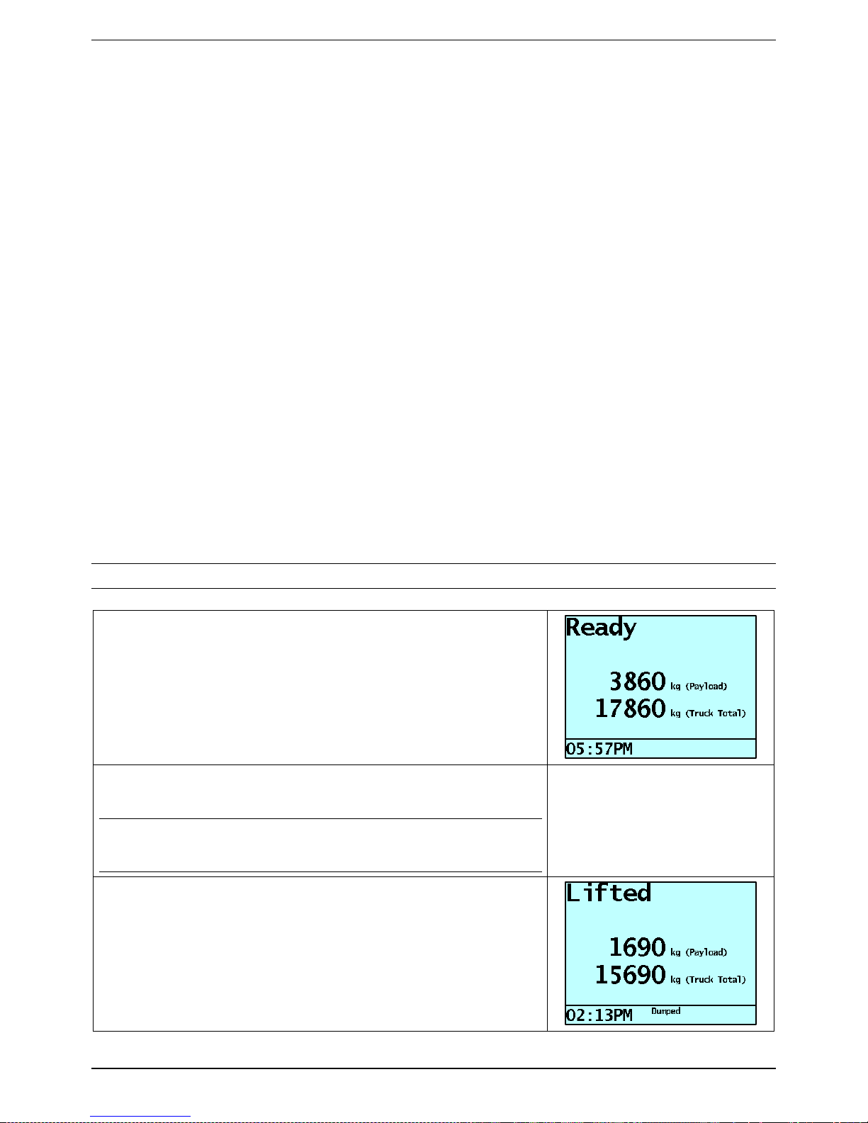
NOTE: Weights shown are examples only.
Before Weighing starts, the display should show the Ready message.
The current truck Payload is displayed.
Optionally, the Truck Total (gross or ‘all up’) weight of the truck may also
be shown.
Raise the bin through the weighing zone. The message Weighing will display.
As you raise the load past the weighing zone, the E2750 beeps and the Indicator
light flashes to show that the weight has been measured.
NOTE: The ‘Dumped’ message appears on the bottom of the display when the
arms have moved back far enough for the bin to be considered ‘dumped’. If this
message is not displayed, then the down weighing cycle will not occur.
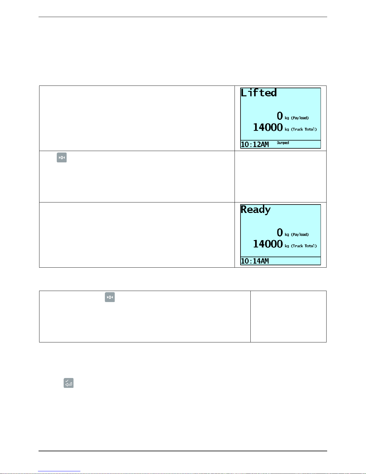
The E2750 will show the Lifted message.
In some trucks the combined bin and material weight may also be displayed. This
is configured at installation.
Continue to lift the bin and empty it in the normal way.
Page 11

2-9
LOADRITE E2750 User Manual
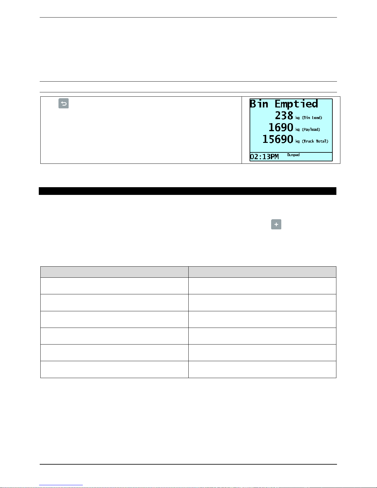
Lower the bin to the ground. As it passes through the weighing zone, the E2750
will again show the Weighing message.
When the weighing is complete, the light will flash. The Bin Load (nett) weight is
then displayed, along with the message Bin Emptied.
The displayed weight is automatically added to the truck total, unless Auto-Add
functionality is disabled.
If Auto-Add is disabled, then the light will remain on for a few seconds, during
which you can:
press to add the displayed weight to the running totals, or
press to zero the measuring system.
If you don’t press a button, the E2750 beeps and prompts you to take action.
If after a further delay, you do not press a button, the E2750 discards the
measured weight and the Ready screen is displayed.
2.2. WEIGHING A LOAD (HOOK LIFT)
This section describes the general weighing process for Hook Lift and similar trucks. (i.e. those trucks that lift a the bin onto the
back of the truck, and weigh once the bin is stationary).
NOTE: Weights shown are examples only.
Load the bin on to the deck of the truck.
Press .
If prompted, press a number key to select the Bin Size. (See table in next section).
This will subtract the nominal Tare (empty) weight for that sized bin.
The Indicator will weigh the bin and display the weight.
NOTE: The system checks that the bin is not moving (weight value is stable)
before recording the weight.
The Nett (contents) weight of the bin will be displayed.
Page 12
2-10
LOADRITE E2750 User Manual
2.3. RECALLING LAST BIN WEIGHT
The recall function recalls and displays the last Bin weight if it has timed out. Recalling is equivalent to lifting the same weight
again, however it will only work if the previous Bin weight timed out.
2.3.1. To recall the previous Bin weight
NOTE: Weights shown are examples only.
Press .
The E2750 displays the previous weight.
2.4. ENTERING BIN SIZES
Depending on your business requirements, you may not need to enter a bin size before lifting the bin.
The E2750 uses the size of the bin as part of the weight calculation. There are up to nine different bin sizes available (numbered
1 to 9) which are configured at the time of the system configuration.
Front Lift: To enter the bin size on Front Lift, press the number button for the required bin BEFORE lifting the bin.
Hook Lift: To enter the bin size on Hook Lift, select the Bin Size if prompted, after pressing the .
2.4.1. Bin Size Record
The bin sizes for your system can be recorded below for easy reference:
Bin Size #
Actual size
Page 13

3-11
LOADRITE E2750 User Manual
3. TOTAL
The E2750 displays each weight measured and the truck total as you add Bin weights.
3.1. TO CLEAR THE TOTAL
Press (normally done at the transfer station).
The Indicator clears the Total and then displays: Cleared Total
The E2750 may also be configured to request the weighbridge weight be entered after the Total is cleared. If prompted, enter
the weighbridge total value, then press .
3.2. LONG TOTAL
In addition to the normal truck Total, a Long Total is recorded. The Long Total is normally used to record the total hauled for a
day or week.
3.2.1. To display the Long Total
Press .
The Long Total is displayed while is held down, and for a few seconds after it is
released.
3.2.2. To clear the Long Total
While the Long Total is displayed, press .
The E2750 prompts you to confirm that you do want to clear the Long Total.
Press to confirm.
The Indicator clears the Long Total.
Page 14
4-12
LOADRITE E2750 User Manual
4. ZEROING THE E2750
When you raise and then lower empty forks or arms through the weighing zone, the Indicator should display 0. However, due to
changes in the lifting arms (mainly caused by temperature), a small zero error may occur. This is mostly automatically
compensated for by the E2750 when the empty weight of the bin is measured.
4.1. TO ZERO THE E2750 (FRONT LIFT AND REAR LIFT)
With empty forks/comb, fully raise (all the way to the dump position) and then lower
the arms.
The display will show Bin Weight: and a weight of 0 or another value.
Press .
The E2750 performs the zero adjustment, then displays Zeroed.
`
The E2750 then returns to the Ready screen.
4.2. TO ZERO THE E2750 (HOOK LIFT)
With the truck empty, press .
The E2750 performs the zero adjustment, then displays Zeroed.
4.3. LARGE ZERO ERROR
If while zeroing, there is a large zero error (displayed weight greater than 5% of full scale), the E2750 will prompt you to confirm
that the forks, arms or deck are empty.
Press to confirm forks are empty, or press any other button if not.
Depending on your response, the Indicator displays Zeroed or Not Zeroed.
Page 15
5-13
LOADRITE E2750 User Manual
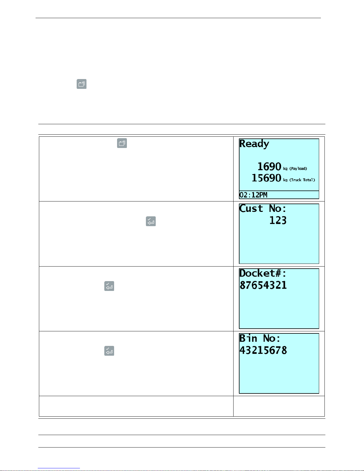
5. ADDITIONAL DATA
If this feature is enabled, the E2750 allows you to enter up to three user-defined numbers, which provide additional information
to the weight data. The specific data for the E2750 is set up at installation time. Examples for the labels attached to the data are:
Cust No:
Docket#:
Bin No:
When you press , the E2750 displays the three labels in sequence and you can enter the relevant numbers for the current
load. The numbers can be up to 8 digits long. This information can be printed or logged to an on-board computer, data logger,
modem or other device (if fitted).
5.1. TO ENTER ADDITIONAL DATA
NOTE: This explanation uses the example labels above
When the E2750 is Ready, press .
The E2750 displays the first label (for example, Cust No) and prompts you to enter
a number.
Enter a number (up to eight digits), then press .
The E2750 displays the second label (for example, Docket#) and prompts you to
enter a number.
Enter a number, then press .
The E2750 displays the third label (for example, Bin No) and prompts you to enter a
number.
Enter a number, then press .
The E2750 then returns to the Ready screen.
NOTE: You may have one, two or three label / number pairs available, depending on how the E2750 is configured at
installation.
Page 16

6-14
LOADRITE E2750 User Manual
6. USER MENU OPTIONS
The User Menu allows you to set the clock and access some diagnostic functions. It also provides access for LOADRITE
installers to calibrate and configure the E2750 (requires a security code).
6.1. USING THE USER MENU
The same buttons are used for all menu options as follows:
To access the menu, press .
To obtain the next menu option, use the arrow keys.
To accept an option, press .
To exit the menu, press .
If you do not press a key, the E2750 returns to the Ready state after a short delay.
6.2. SETTING THE TIME AND DATE
The E2750 has an internal clock which can be used for inserting the time and date into recorded and printed data.
6.2.1. To set the time and date
When the E2750 is Ready, press .
Press and the display should show: Clock?
To set the clock, press .
The E2750 shows the current time and prompts you to enter the minutes.
Enter the correct minutes using the number keys, then press .
You can clear mistakes using .
Enter the correct hours using the number keys.
Use and to toggle AM/PM setting.
When the hours are correct, press .
Enter the correct month using the number keys, then press .
Enter the correct date using the number keys, then press .
Enter the correct year using the number keys, then press .
Finally, the E2750 displays the complete time and date for a few seconds before
returning to the Ready state.
TIP: At any time while entering the time and date you can press to return the E2750 to the Ready screen without altering
the current time and date.
Page 17

7-15
LOADRITE E2750 User Manual
7. PRINT FUNCTIONS
When an LP930 or LP950 printer is connected, weight data can be printed as the E2750 weighs. Most print options can be
configured at installation.
The data can be automatically printed when particular functions are performed as listed below.
At start-up
E2750
Always printed
Weight added
Weight
Sequence Number
Time
User Defined Data 1
User Defined Data 2
User Defined Data 3
Always printed
Optional
Optional
Optional
Optional
Optional
Short total cleared
Total Weight
User Defined Data 1
User Defined Data 2
User Defined Data 3
ID Number (truck)
Time and Date
User Title (company name)
Optional
Optional
Optional
Optional
Optional
Printed if total printed
Printed if total printed
Long total cleared
Long Total Weight
ID Number (truck)
Time and Date
Always printed
Always printed
Always printed
Zero performed
Weight Zeroed
Always printed
7.1. RECEIPT PRINTING
The E2750 has an optional function that allows a customer receipt to be printed as required. This function is useful if a receipt
needs to be given to the customer when a bin is emptied.
When enabled, after a bin has been emptied and the weight added to the Total, a receipt can be printed by pressing .
Depending on options selected at installation, a receipt similar to below will be printed:
-------------------Sands Hauling
Bin Nett: 450kg
Bin Size: 1
Truck Number: 456
Date: 1 Jun 2017
Time: 12:30 pm
--------------------
Page 18

8-16
LOADRITE E2750 User Manual
8. APPENDIX A: SPAN CALIBRATION
CORRECTION
This function allows small changes to be made to the E2750 calibration if the arms or lifter of the truck are modified or if no
accurate test weight is available when the E2750 is calibrated at installation time.
The adjustment is carried out by entering the total of weights recorded at a weighbridge (scale house) over a period of time and
the corresponding E2750 total.
To perform the adjustment, you need to obtain a security access code from your LOADRITE installer.
CAUTION
The E2750 alters its calibration every time this function is used. It is important that you only use this function once with a given
set of data. If the same weights are entered again, the E2750 will over-correct and its accuracy will be seriously impaired.
Example
A truck is loaded and then proceeds to a weighbridge (scale house). The totals for the loads in this example are as follows:
E2750
6000kg
Weighbridge
6200kg
8.1. TO CORRECT THE CALIBRATION OF THE E2750
Press , then press .
The E2750 prompts you to enter the security access code.
Enter the access code, then press .
The E2750 prompts you to enter the LOADRITE value for the weight.
Enter the LOADRITE weight (6000 in this example), then press .
Page 19

8-17
LOADRITE E2750 User Manual
The E2750 prompts you to enter the weighbridge value.
Enter the weighbridge weight (6200 in this example), then press .
If the adjustment is within limits, the E2750 alters its calibration, briefly displays a
value of scale factor and then returns to the Ready screen.
If the required adjustment is too large, the E2750 displays an error message and
does not change its calibration.
8.2. CHECKING THE ADJUSTMENT
You can check the calibration adjustment by obtaining and comparing new LOADRITE and weighbridge totals. If necessary, the
calibration adjustment can be performed again using the new data.
Notes to remember:
It is important that you only use this function once with a given set of data. If the same weights are entered again, the
E2750 will over correct and its accuracy will be seriously impaired.
It is very important to measure the empty (Tare) weight of the truck when it has dumped its load. Stored Tares can be
inaccurate and cause the system to be incorrectly calibrated.
Page 20

9-18
LOADRITE E2750 User Manual
9. APPENDIX B: ERROR MESSAGES
9.1. CONTACT LOADRITE
A problem has occurred upgrading software has occurred. Contact your LOADRITE distributor for assistance.
9.2. CONTACT LOADRITE 1010
The voltage of the Indicator battery has dropped below 2.7V. Contact your LOADRITE distributor for assistance.
9.3. DEMO MODE!
The Indicator is currently in Demo mode. An access code must be entered to end Demo mode. Contact your LOADRITE
distributor for more information.
9.4. LIMP MODE!
One of the strain link sensors has failed, but your LOADRITE Distributor has enabled Limp Mode to allow the E2750 Weighing
System to continue weighing at reduced accuracy until repairs can be made. Contact your LOADRITE distributor for more
detailed information.
9.5. LOW POWER
A power problem has been detected. There are two typical causes:
The power supply voltage to the E2750 has fallen below 11V DC (can occur during cranking on 12V trucks).
A cable connecting to a sensor has been damaged and is compromising the power supply (often this is the cable to the
Amplifier or Loadcell).
Contact your LOADRITE distributor for assistance.
9.6. NO DUMP. ADD?
This error message indicates that the forks have not returned to the “dump” position as part of the weigh. This means that the
Auto-Add functionality cannot add the weight to the Total.
The operator must manually add the measured weight if valid. For more information on adding weights, refer to “To weigh a
load” on page 2-8.
9.7. OVER R1 / OVER R2
There is a fault in one of the loadcells or cables. Contact your LOADRITE distributor for assistance.
9.8. TILT FAULT
An Angle Sensor fault has been detected. There are two typical causes:
The Angle sensor is damaged or faulty.
The cable from the Angle Sensor to the Indicator is damaged.
Contact your LOADRITE distributor for assistance.
9.9. TRIGGER FAULT
A Trigger fault has been detected. There are three typical causes:
The Trigger is damaged or faulty.
The cable from the Trigger to the Indicator is damaged.
The steel cable has detached from the cable spool on the Trigger (LR908 sensors only).
Contact your LOADRITE distributor for assistance.
Page 21

10-19
LOADRITE E2750 User Manual
10. APPENDIX C: SPECIFICATIONS
10.1. MINIMAL WEIGHING DELAY
Weighing delay is minimal, because the weighing function is carried out during a normal lift.
10.2. POWER REQUIREMENTS
Supply voltage
12 to 32 Volts DC
Supply current
160mA typical, 350mA max.
LP950 printer
50mA standby, 4A peak.
Automatic transient suppression exceeds relevant SAE specifications for DC automotive power supply transients.
10.3. SIGNAL INPUTS AND OUTPUTS
Loadcell sensor inputs (with LR980 external Interface)
+/- 3mV/V range
General purpose Inputs
Pull to ground
Serial communications
RS232 to printer and data logger.
10.4. DISPLAY / KEYBOARD
Display
Backlit LCD.
Keyboard
20 backlit keys including numeric and special function keys.
10.5. CLOCK
Built in clock provides time and date.
Hours, minutes, AM/PM, day, month, year.
10.6. PHYSICAL
Indicator
Protected to IP54
Dimensions
W 170mm, L 270mm, and H 90mm.
Weight
2kg with mounting bracket
Sensors
Protected to IP67
10.7. OPTIONAL FEATURES
A range of additional operating features can be enabled at installation time.
Page 22

10-20
LOADRITE E2750 User Manual
10.8. OUTPUT/INPUT CONNECTIONS
Connection
Power / Control
Printer
Pressure Transducer (Used to connect the Loadcell Amplifier in non-CAN systems)
10.8.1. Power / Control
1. Negative supply (ground)
2. Positive supply
3. Remote button 2
4. Remote button 1
5. N.C.
6. Interlock
7. N.C.
8. Trigger Positive supply
9. N.C.
10. Rotary trigger
11. N.C.
12. CAN Hi
13. CAN Lo
14. Positive output supply
15. Ground output
10.8.2. Printer
1. Negative supply to printer
2. Positive supply to printer
3. +12V output (do not use)
4. N.C.
5. N.C.
6. Printer RS232 output
7. Printer busy input
8. EDP RS232 input
9. EDP RS232 output
10. Ground output
11. Reserved
12. N.C.
Page 23

10-21
LOADRITE E2750 User Manual
10.8.3. Analog Input (Labelled “Pressure Transducer”)
1. Loadcell power
2. Analog input 2 (from sensor amplifier)
3. Do not connect
4. N.C.
5. Analog input 1 (from sensor amplifier)
6. Shield
7. Ground
Page 24

11-22
LOADRITE E2750 User Manual
11. APPENDIX D: LEGAL INFORMATION
Disclaimer
Trimble Inc operates a policy of on-going development. Please note that while every effort has been made to ensure that the data given in this document is accurate,
due to continued product development, the information, figures, illustrations, tables, specifications, and schematics contained herein are subject to change without
notice. Trimble Inc does not warrant that this document is error-free. The screenshots and other presentations shown in this manual may differ from the actual
screens and presentations generated by the actual product. All such differences are minor and the actual product will deliver the described functionality as presented
in this document in all material respects. If you find any errors in the document, please report them to us in writing.
Trimble Inc assumes no liability in connection with the use of any LOADRITE branded product.
Trimble Inc is not responsible for any radio or TV interference caused by unauthorized modifications to this equipment. Such modifications could void the user's
authority to operate the equipment.
Compliance
Domain
Applicable Standard
Immunity Standards (industrial)
IEC 61000-4-3 (ed1.2) Electromagnetic compatibility (EMC) - Part 4-3: Testing and measurement techniques Radiated, radio-frequency, electromagnetic field immunity test (80% 1kHz Amplitude Modulated) from 80MHz to
1GHz 10V/m
IEC 61000-4-3 (ed1.3) Electromagnetic compatibility (EMC) - Part 4-3: Testing and measurement techniques Radiated, radio-frequency, electromagnetic field immunity test (80% 1kHz Amplitude Modulated) from 1.4GHz to
2GHz 3V/m
IEC 61000-4-3 (ed1.4) Electromagnetic compatibility (EMC) - Part 4-3: Testing and measurement techniques Radiated, radio-frequency, electromagnetic field immunity test (80% 1kHz Amplitude Modulated) from 2GHz to
2.7GHz 1V/m
Conducted
IEC 61000-4-6 (ed2.1) Electromagnetic compatibility (EMC) - Part 4-6: Testing and measurement techniques Immunity to conducted disturbances, induced by radio-frequency fields
Fast Transients
IEC 61000-4-4 (ed2.1) Electromagnetic compatibility (EMC) - Part 4-4: Testing and measurement techniques Electrical fast transient/burst immunity test +/1KV (5/50 Tr/Th ns - 5kHz repetition)
ESD
IEC 61000-4-2 Electromagnetic compatibility (EMC) - Part 4-2: Testing and measurement techniques Electrostatic discharge immunity test +/-4kV / Electrostatic Air Discharge +/-8kV
Electromagnetic compatibility (EMC)
EN/IEC/ASNZS 61000-6-2:2005 Electromagnetic compatibility (EMC) - Part 6-2: Generic standards - Immunity for
industrial environments
EN/IEC 61000-6-4:2005 Electromagnetic compatibility (EMC) - Part 6-4: Generic Standards - Emission standard
for industrial environments
ANSI C63.4:2003 FCC Part 15 (A and B) - Radio Frequency Devices
Products with the CE marking comply with the Electromagnetic Compatibility Directive (2004/108/EC) issued by the Commission of the European Community.
Compliance with this directives implies conformity to the following European Standards:
EN 61000-6-2:2005 Electromagnetic compatibility (EMC) - Part 6-2: Generic standards - Immunity for industrial environments
EN 61000-6-4:2005 Electromagnetic compatibility (EMC) - Part 6-4: Generic Standards - Emission standard for industrial environments
The Indicator is fully EMC (Electro-Magnetic Compatibility) compliant and is CE marked accordingly. A Declaration of Conformity, in accordance with the EMC
Directive 89/336/EEC (and as amended) is available from Trimble Inc on request: info@LOADRITEscales.com
Trimble Inc cannot be held responsible for modifications made by the User and the consequences thereof, which may alter the conformity of the product with CE
marking.
Hereby, Trimble Inc, declares that this LOADRITE E2750 is in compliance with the essential requirements and other relevant provisions of Directive 2004/108/EC.
The Indicator is compliant with RoHS Directive 2002/95/EC which sets limits for the use of certain restricted hazardous substances. This directive states that “from
1st July 2006, new electrical and electronic equipment put on the market does not contain lead, mercury, cadmium, hexavalent chromium, polybrominated biphenyls
(PBB) or polybrominated diphenyl ethers (PBDE)”.
This device complies with part 15 of the FCC Rules and Industry Canada licence-exempt RSS standard(s). Operation is subject to the following two conditions: (1)
This device may not cause harmful interference, and (2) this device must accept any interference received, including interference that may cause undesired
operation.
This Class A digital apparatus complies with Canadian ICES-003 (A) / NMB-003 (A).
WARNING: This product contains chemicals known to the State of California to cause cancer, birth defects or other reproductive harm. This
Notice is being provided in accordance with California's Proposition 65.
Disposing of the LOADRITE Indicator
This electronic product is subject to the EU Directive 2002/96/EC for Waste Electrical and Electronic Equipment (WEEE) which requires the
separate collection, treatment, recycling and environmentally-sound final disposal of waste of electrical and electronic equipment. As such, this
product must not be disposed of at a municipal waste collection point.
Please refer to local regulations for directions on how to dispose of this product in an environmentally friendly manner.
Page 25

Page 26

45 Patiki Road, Avondale, Auckland 1026
PO Box 19623, Avondale, Auckland 1746
New Zealand
Tel: +64 9 820 7720
Fax: +64 9 820 7721
trimble.com
loadritescales.com
 Loading...