

Page 1
LL200 Laser Level
User Guide
www.trimble.com
•
– 2 –
– 5 –
– 9 –
– 3 – – 4 –
– 6 –
– 10 –
– 7 –
– 11 –
– 8 –
– 12 –
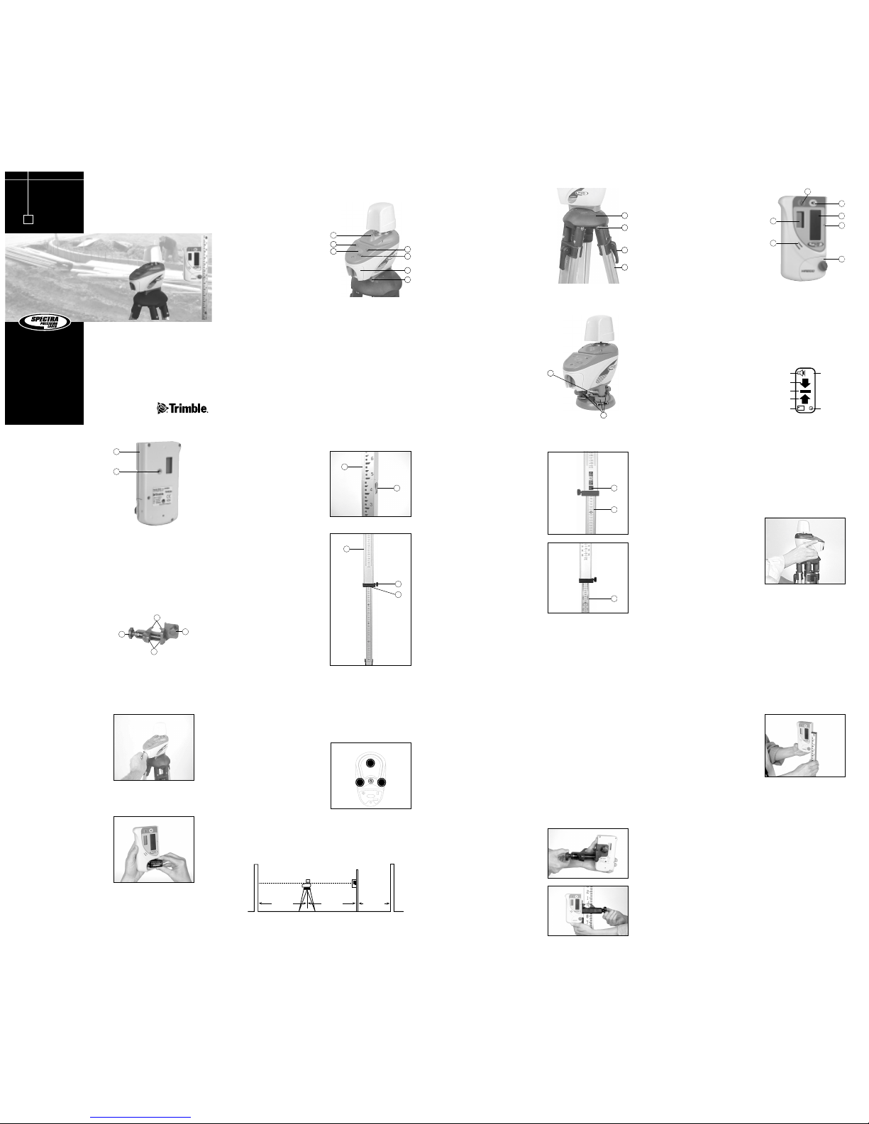
Features and Functions
Model LL200
08. Leveling Dome –
provides a surface for the
laser’s leveling base to
move around on so the
laser can be leveled.
09. 8-mm Cap Screws –
attach the tripod’s
leveling dome to the
tripod’s legs.
10. Leg Clamps – lock/
unlock so the height of
the laser can be adjusted.
HR200 Receiver
1. Power Button – turns the
receiver on/off.
2. Audio Button – turns the
audio on/off.
3. Photocell– detects the
laser beam when it strikes
the receiver. If the photocell
does not detect the laser
beam for eight minutes,
the receiver shuts off
automatically.
4. Marking Notches (front and back) – align with the
on-grade portion of the photocell and are used to mark
elevation readings. The marking notches are 2 inches
(50 mm) from the top of the receiver.
5. Battery Housing – holds one 9-V alkaline batter y. The
battery-housing door is used to attach the receiver to the
grade rod.
6. Audio Port – is the opening the sound comes out of.
7. Front and Back Liquid
Crystal Displays (LCDs) –
show the power, audio,
grade, and battery status.
The LCDs also show when
the laser has been bumped
out of level.
HR200 Receiver (cont.)
8. Groove – is the channel that
the grade-rod tongue fits
into so the receiver can be
attached to the grade rod.
9. Clamp-Screw Opening –
is the threaded brass insert
that allows an optional
1271-1 general-purpose
clamp to be attached to
the receiver.
1271-1 General-Purpose Clamp
The 1271-1 general-purpose clamp allows the receiver to be
attached to a survey rod or wooden 2 x 2 when the 8-ft grade
rod isn’t long enough for applications such as excavating
basements.
1. Receiver Screw – fits into the clamp-screw opening on
the back of the receiver so the receiver can be attached to
a general-purpose clamp.
Grade Rods 0205-2510, 0205-2520, and 0205-2540
1. Tongue – fits into the
receiver groove so the
receiver can be slid
up/down the grade rod.
2. Release Buttons (3) –
snap/unsnap so the grade
rod can be assembled/
disassembled.
Grade Rod 0205-2530
1. Tongue – fits into the
receiver groove so the
receiver can be slid
up/down the grade rod.
2. Extension-Clamp Knob –
turns clockwise/
counterclockwise to
hold/release the upper
rod section.
3. Reading Edge – marks the
elevation where all grade
rod readings are taken.
4. Release Buttons (2) –
snap/unsnap so the grade
rod can be extended/
retracted.
5. Back-Side Scale –
measures between 0.55 and
1.36 meters (1 foot
10 inches and 4 feet
5 inches).
Laser
1. Turn the battery-housing
knob counterclockwise to
release the battery-housing
door.
2. Insert the battery as shown
noting the plus (+) and
minus (–) diagram inside
the housing.
3. Put the battery-housing door in place and turn the batteryhousing knob clockwise.
Receiver
1. Turn the battery-housing
knob counterclockwise to
release the battery-housing
door.
2. Insert the battery as shown
noting the plus (+) and
minus (–) diagram inside
the housing.
3. Put the battery-housing
door in place and turn the
battery-housing knob
clockwise.
Setting Up and Leveling the Laser
1. Set up the laser in the middle of your work area (or
wherever is best for your application needs). Make sure
the setup is stable.
3. Level the laser using the bull’s eye as a reference.
CAUTION: When leveling the LL200, be sure not to rotate
the laser more than 360°. Doing so can cause the extension
spring that holds the laser to the leveling base to break. If
rotating the laser becomes difficult, turn the laser 180° in
the opposite direction.
Note: When the laser is level, the bubble is centered in the
bull’s-eye and the green level LED lights. The LED stays lit
for the first five minutes the laser is level then flashes once
every five seconds.
Attaching the Receiver to the Grade Rod
With the 1271-1 General-Purpose Clamp
Without the 1271-1 General-Purpose Clamp
Safety Information
Included in this manual are CAUTIONS and Notes. Each of
these words represents a level of danger or concern.
A CAUTION indicates a hazard or unsafe practice that could
result in minor injury or property damage.
A Note indicates important information unrelated to safety.
How to Use the Model LL200
1. Power Button – turns the
laser on/off.
2. Out-of-Level LED (red) –
flashes when the laser is out
of level. If the laser is out of
level for 15 minutes, it
shuts off automatically.
3. Bull’s-Eye Level – provides
an easy reference for
leveling the laser.
4. Low-Battery LED (red) –
flashes when the battery
power is low. The laser operates for a minimum of two
hours after the LED starts flashing.
5. Level LED (green) – lights when the laser is on and level.
6. Battery Housing – holds one 1.5 V D-cell alkaline battery.
7. Leveling Base – moves around on the tripod’s leveling
dome so the laser can be leveled.
9
10
11
2
1
3
4
5
ON
+
Audio
Above Grade
On Grade
Below Grade
Low Battery
Power
Out of Level
Liquid Crystal Display (LCD)
7
6
8
9
2. Jaws– open/close so the
general-purpose clamp can
be attached to the grade
rod.
3. Jaws Screw – controls the
opening/closing of the jaws.
3
1
4
2
4. Alignment Marks – align with the receiver’s on-grade
marking notches.
1
2
1
2
3
6
4
5
6. Front-Side Scale –
measures between 1.30
and 2.11 meters (4 feet
3 inches and 6 feet
11 inches). The upper
section of both sides has an
80-cm (24-in.) scale. This
scale has 40 cm (12 in.)
that are positive and 40 cm
(12 in.) that are negative
and shows the amount
of cut/fill.
CAUTION: Be sure to handle
the laser by the body rather
than the top (sunshade). The
sunshade protects the glass
window that the beam comes
out of. The window can break
if handled improperly.
Installing the Batteries
Note: The laser and receiver have reverse polarity protection.
If you put the batteries in wrong, no damage occurs to the laser
and receiver but they do not work. Allow them one minute to
recover after the batteries have been installed correctly.
Y
X
X
Note: The maximum
operating diameter is
430 ft (130 m) in the
Y axis and 1000 ft
(300 m) in the X axis.
The minimum operating
distance to a wall is
20 ft (6 m).
20 ft (6 m)
minimum
20 ft (6 m)
minimum
5 ft (1.5 m)
minimum
1. Attach the clamp to the
receiver.
1. Turn the battery-housing
knob counterclockwise to
loosen the battery-housing
door.
2. Slide the receiver onto the
grade rod.
3. Turn the battery-housing
knob clockwise to hold the
receiver securely in place.
Using the Receiver
11. Legs – support the laser and allow the height of the laser
to be adjusted.
Model LL200-4
The Model LL200 and Model
LL200-4 are the same except
for the leveling base.
1. Leveling Screws – turn
clockwise/counterclockwise
so the laser can be leveled.
2. Threaded Brass Insert –
allow the laser to be
attached to a standard
5
/8-11 construction tripod.
1
2
8
2. Attach the clamp to the
grade rod.
4
5
6
7
1
2
3
Note: For best system performance, do not set up the laser
within 20 ft (6 m) of a wall. Also do not use the receiver
within 20 ft (6 m) of the laser or within 5 ft (1.5 m) of a
wall. At these close ranges, the receiver’s electronics may give
incorrect beam elevation information due to the laser beam
reflecting off of the walls.
2. Press the power button to turn on the laser. All LEDs flash
once to show that they are working.
1. Attach the receiver to the grade rod.
2. Press the power button to turn on the receiver. The ON
symbol appears in the LCD.
3. If you’re using the audio function, press the audio button to
turn it on. The audio symbol appears in the LCD.
Note: The receiver beeps quickly when the receiver is above
the laser beam, slowly when below it, and continuously
when centered in the laser beam or on grade. If, however,
the laser gets bumped out of level while it is being used, the
receiver beeps once every second.
Page 2

Declaration of Conformity
Application of 89/336/EEC
Council Directive(s):
Manufacturer’s Name: Trimble Navigation Limited
Manufacturer’s Address: 5475 Kellenburger Road
Dayton, Ohio 45424-1099
U.S.A.
European Representative Trimble GmbH
Address: Am Prime Parc 11
65479 Raunheim, Germany
Model Number(s): LL200/HR200
Conformance to EC Directive 89/336/EEC using
Directive(s): EN55022 and EN50082-1
Equipment Type/ ITE/residential, commercial
Environment: & light industrial
Product Standards: Product meets the limit B and
methods of EN55022
Product meets the levels
and methods of IEC 801-2,
8 kV air, 4 kV contact
IEC 801-3, 3 V/m 26 to 1000
MHz 80%, @ 1 kHz
Warranty
Trimble warrants the laser system (laser, receiver, tripod, and
grade rod) to be free of defects in material and workmanship
for a period of one year. The Warranty is in effect twelve
months from the date the system is delivered by Trimble or its
authorized dealer to the purchaser, or is put into service by a
dealer as a demonstrator or rental component. If the laser fails
due to damage to the beam reflecting compensator or laser
source, those components will be repaired or replaced at no
charge during the original warranty period.*
Special precautions have been taken to ensure the calibration
of the laser; however, calibration is not covered by this
warranty. Verifying the laser’s calibration is the responsibility
of the customer.
Trimble or its authorized service center will repair or replace,
at its option, any defective part for which notice has been given
during the warranty period. If required, travel and per diem
expenses to and from the place where repairs are made will be
charged to the customer at the prevailing rates.
Customers should send the product to Trimble or the nearest
authorized service center for warranty repairs, freight prepaid.
In countries with Trimble subsidiary service centers, the
repaired product will be returned to the customer, freight
prepaid.
– 13 – – 14 – – 15 – – 16 –
–
17 – – 18 –
– 19 – – 20 –
– 21 – – 22 – – 23 –
✔
N324
Trimble Construction Division
5475 Kellenburger Road
Dayton, Ohio 45424-1099
U.S.A.
+1-937-245-5600 Phone
www.trimble.com
© 2002-2005, Trimble Navigation Limited. All rights reserved.
Reorder PN 0205-0080 Rev. C (07/05)
Receiver (cont.)
4. Position the receiver so
that its photocell faces
the laser. For best results,
the photocell should be as
perpendicular to the laser
as possible.
Determining the Height of Instrument (HI)
The height of instrument (HI) is the elevation of the laser’s
beam. The HI is determined by adding the grade-rod reading
to a benchmark or known elevation.
1. Set up and level the laser.
2. Attach the receiver to a grade rod and turn on the receiver.
3. Place the grade rod on a job-site benchmark (BM) or known
elevation.
4. Slide the receiver up/down the grade rod until the LCD
shows an on-grade reading.
5. Add the grade-rod reading to the benchmark to determine
the height of instrument.
Example: Benchmark elevation = 100.23 ft (30.55 m)
On-grade rod reading = + 4.34 ft (1.32 m)
Height of instrument = 104.57 ft (31.87 m)
6. Use this HI as a reference for all other elevations.
Specifications
Laser
Accuracy ±15 arc seconds
or ±3/32 in./100 ft (±2.2 mm/30 m)
Operating Diameter 430 ft (130 m)—Y axis
1000 ft (330 m)—X axis
Minimum Operating Range 20 ft (6 m)
Self-Leveling Range ±30 minutes
Level Bubble Sensitivity 45 arc minutes/0.1 inch movement
Out-of-Level Indication Flashing LED
Power Source One 1.5 V D-cell alkaline battery
Battery Life 100 hours @ 70 °F (23 °C)
Low Battery Operation 2 hours minimum
Automatic Shutoff 15 minutes if the laser is not level
Tripod Mount
5
/8-11
Water Resistant Yes
Operating Temperature –10 °F to 120 °F (–23 °C to 50 °C)
Storage Temperature –40 °F to 140 °F (–40 °C to 60 °C)
Laser Type/Classification 780 nm IR/Class 1
Regulatory Conformance CDRH: Class 1
EC Directive 89/336/EEC using
EN55022 and EN50082-1
Receiver
Accuracy <±1/16 in. (±1.5 mm)
Elevation Readout Front and back LCDs
Out-of-Level Indication Audio and visual
Audio Control On/Off
Capture Height 2 in. (50 mm)
Marking Notches 2 in. (50 mm) below top of receiver
Power Source One 9-V alkaline battery
Battery Life 45 hours
Low Battery Operation 1 hour
Automatic Shutoff 8 minutes
Water Resistant Yes
Operating Temperature –10 °F to 120 °F (–23 °C to 50 °C)
Storage Temperature –40 °F to 140 °F (–40 °C to 60 °C)
Regulatory Conformance RFI (Radio Frequency Interference
Protection) per 89/336/EEC using
EN55022 and EN50082-1
CAUTION: When checking all four axes for a calibration
error, be sure not to rotate the laser more than 360°. Doing
so can cause the extension spring that holds the laser to the
leveling base to break. If rotating the laser becomes difficult,
turn the laser 180° in the opposite direction.
1. Set up and level the laser 100 ft (30 m) from a wall.
Checking Calibration
As with any precision instrument, the calibration needs
checking on a regular basis (such as at the beginning of a job,
or if the laser has been handled roughly). If the laser is being
used at temperatures below freezing, be sure to check
calibration under those conditions.
The laser is calibrated if the laser plane is within ±3/32 inch
(±2.2 mm) of true level at 100 ft (30 m). If the laser has a
calibration error, go to the “Request for Service” section of
this manual to get more information.
2. Use the receiver to take an elevation reading for the +Y axis.
Request for Service
To locate your local dealer or authorized Trimble Service
Center outside the U.S.A for service, accessories, or spare parts,
contact one of our offices listed below.
North America
Trimble Construction Division
5475 Kellenburger Road
Dayton, Ohio 45424-1099
U.S.A.
(800) 538-7800 (Toll Free)
+1-937-245-5600 Phone
+1-937-233-9004 Fax
Europe
Trimble GmbH
Am Prime Parc 11
65479 Raunheim
GERMANY
+49-6142-2100-0 Phone
+49-6142-2100-550 Fax
Latin America
Trimble Navigation Limited
6505 Blue Lagoon Drive
Suite 120
Miami, FL 33126
U.S.A.
+1-305-263-9033 Phone
+1-305-263-8975 Fax
Africa & Middle East
Trimble Export Middle-East
P.O. Box 17760
Jebel Ali Free Zone, Dubai
UAE
+971-4-881-3005 Phone
+971-4-881-3007 Fax
Asia-Pacific
Trimble Navigation
Australia PTY Limited
Level 1/120 Wickham Street
Fortitude Valley, QLD 4006
AUSTRALIA
+61-7-3216-0044 Phone
+61-7-3216-0088 Fax
China
Trimble Beijing
Room 2805-07, Tengda Plaza,
No. 168 Xiwai Street
Haidian District
Beijing, China 100044
+86 10 8857 7575 Phone
+86 10 8857 7161 Fax
www.trimble.com.cn
EMC Declaration of Conformity
This laser has been tested and found to comply with the limits
for a Class B digital device for radio noise for digital apparatus
set out in the Radio Interference Regulations of the Canadian
Department of Communication, and is pursuant to part 15 of
the Federal Communication Commission (FCC) rules. These
limits are designed to provide reasonable protection against
harmful interference in a residential installation. This laser
generates radio frequency. If it’s not used in accordance with
the instructions, it may cause harmful interference to radio or
television reception. Such interference can be determined by
turning the laser off and on. You are encouraged to try
eliminating the interference by one or more of the following
measures:
• Reorient or relocate the receiving antenna.
• Increase the separation between the laser and the receiver.
For more information, consult your dealer or an experience
radio/television technician.
CAUTION: Changes or modifications to the laser that are not
expressly approved by Trimble Construction Instruments
Division could void authority to use the equipment.
Any evidence of negligence or abnormal use, including a
broken lighthouse, or any attempt to repair the product by
other than factory-authorized personnel using Trimble certified
or recommended parts, automatically voids the warranty.
The foregoing states the entire liability of Trimble regarding
the purchase and use of its equipment. Trimble will not be held
responsible for any consequential loss or damage of any kind.
This warranty is in lieu of all other warranties, except as set
forth above, including any implied warranty merchantability
of fitness for a particular purpose, are hereby disclaimed. This
warranty is in lieu of all other warranties, expressed or implied.
}
±3/32 inch
(±2.2 mm)
100 ft (30 m)
True Level
Calibration Error
100 ft (30 m)
+ Y
Y
1
100 ft (30 m)
-Y
3. Rotate the laser 180° (–Y axis toward the wall) and re-level
the laser.
HI
Rod Reading
4.34 ft (1.32 m)
Benchmark
100.23 ft (30.55 m)
HI = Rod Reading + Benchmark
HI = 4.34 ft + 100.23 ft = 104.57 ft (1.32 m + 30.55 m = 31.87 m)
Height of Instrument (HI)
4. Use the receiver to take an elevation reading for the –Y axis.
5. Calculate the difference between the two elevation readings.
If they differ more than 3/16 in. (4.4 mm), the laser needs
calibrating. Return the laser to an authorized Trimble service
center for servicing.
6. To check the X axis, repeat steps 1–5 using the X axis
instead of the Y axis.
Above Grade
On Grade
Below Grade
Out of Level
ON
Laser Safety
The United States Government Center of Devices for
Radiological Health (CDRH) has classified this laser as a Class
1 laser product. The classification is the safest one available in
that it uses laser energy similar to that used in a compact disc
player. A Class 1 certification means that NO risk of injury
exists when this laser product is used in accordance with the
instructions in this manual.
CAUTION: If you’re using an optical instrument within
10 ft (30 m) of the laser, do not point it toward the laser.
No OSHA or ANSI requirements with regard to signs,
warning labels, or operator’s licensing are needed because of
the laser’s low operating power. Question about laser safety
should be address to:
Trimble Navigation Limited
5475 Kellenburger Road
Dayton, OH 45424-1099 U.S.A.
Attention: Quality Assurance Group, Laser Safety Officer
Phone: (937) 245-5824
(800) 538-7800
FAX: (937) 233-9661
Labels required for this product:
The DANGER label is under the sunshade and
is visible only when the product is serviced by an
authorized repair technician.
D
A
N
G
E
R
I
N
V
I
S
I
B
L
E
L
A
S
E
R
R
A
D
I
A
T
I
O
N
A
V
O
I
D
D
I
R
E
C
T
E
X
P
O
S
U
R
E
Complies with CFR 1040 as applicable.
U.S. PATENTS: 4,679,937
4,767,208
4,674,870
5,257,279
4,732,471
4,111,564
Model:
✔
N324
S/N MFG:
5. Turn the battery-housing
knob counterclockwise
slightly to loosen the battery-housing door. (If you are using
the general-purpose clamp, turn the jaws screw to loosen the
jaws.) Slide the receiver up/down the grade rod until the
LCD shows an on-grade reading.
Note: The LCD shows
a down arrow when the
receiver is above the laser
beam, an up arrow when
below it, and a horizontal
line when centered in the
laser beam or on grade.
If, however, the laser gets
bumped out of level while it is being used, the LCD shows
an out-of-level level bubble (the same symbol as appears on
the laser).
6. Turn the battery-housing knob (jaws screw) clockwise to
hold the receiver securely in place.
Note: The receiver can also be used without the grade rod.
Notice to Our European Union Customers
For product recycling instructions and more information,
please go to: www.trimble.com/environment/summary.html
Recycling in Europe
To recycle Trimble WEEE, call: +31 497 53 2430, and ask for the “WEEE
associate,” or
mail a request for recycling instructions to:
Trimble Europe BV
c/o Menlo Worldwide Logistics
Meerheide 45
5521 DZ Eersel, NL
 Loading...