

Page 1

HV401
© 2005,Trimble Navigation Limited. All rights reserved
PN Q103159 rev.B (03/07)
Trimble Construction Division
5475 Kellenburger Road
Dayton, Ohio 45424-1099
USA
+1-937-245-5600 Phone
User Guide
Bedienungsanleitung
Manuel de l´utilisateur
Guida per l´uso
Gúia del usuario
Gebruikershandleiding
Operatörshandbok
Betjeningsvejledning
Guia do Usuário
Bruksanvisning
Käyttäjän opas
3\ɤɨɜɨɞɫɬɜɨɩɨɥɶɡɨɜɚɬɟɥɹ
070365_Umschlag_HV401 18.04.2007 14:42 Uhr Seite 1
Page 2
Printed in Germany Q103159 rev. B (03/07)
13
21
12
11
10
13
14
15
18 1616 17
20
19
21
20
7
6
3
5
4
8
7
1
2
9
8
9
070365_Umschlag_HV401 18.04.2007 14:42 Uhr Seite 2
Page 3
5
• Use of this product by people other than those trained on this product may result in exposure to hazardous
laser light.
• Do not remove warning labels from the unit.
• The laser is subject to class 3A/3R (< 5mW, 600 ... 680 nm).
• Never look into the laser beam or direct it to the eyes of other people.
• Always operate the unit in a way that prevents the beam from getting into people‘s eyes.
If initial service is required, which results in the removal of the outer protective cover, removal must only be
performed by factory-trained personnel.
Caution: Use of other than the described user and calibration tools or other procedures may result
in exposure to hazardous laser light.
Caution: Using the unit different than described at the HV401 user guide, may result in unsafe
operation.
The HV401 is a simple-to-use laser that allows you to take accurate horizontal/vertical measurements, 90°and plumb point transfer.
TABLE OF CONTENTS
FOR YOUR SAFETY 5
COMPONENTS 6
How to Use the Laser System 6
Powering the Laser 6
Laser Setup 7
Turning On/Off the Laser 7
Activating/Deactivating Standby Mode 7
Using the Rotation Mode 7
Plunging the Beam 8
Using the Pointing Mode 8
Using the Scan Mode 8
Using the Manual Mode 8
Using the Y- or X-Axis Single Slope Mode 9
APPLICATIONS 9
Interior 9
Acoustical Ceilings 9
Drywall and Partitions 9
General Construction 10
Determining the Height of Instrument (HI) 10
Establishing Vertical Alignment 10
Using the Y-Axis Single Slope Mode 10
CALIBRATION 11
Checking Calibration of the Y- and X-Axes 11
Checking Calibration of the Z (Vertical) Axis 11
M201 UNIVERSAL-MOUNT 12
PROTECTING THE UNIT 13
CLEANING AND MAINTENANCE 13
PROTECTING THE ENVIRONMENT 13
WARRANTY 13
TECHNICAL DATA 14
FOR YOUR SAFETY
For hazardless and safe operation, read all the user guide instructions.
LASER RADIATION
AVOID DIRECT EYE EXPOSURE
CLASS 3A/3R LASER PRODUCT
GB
Page 4

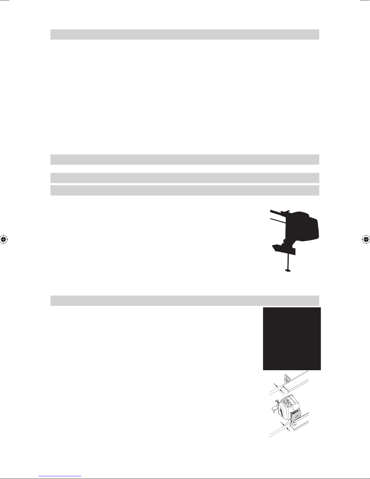
COMPONENTS
1 Power Button
2 Battery LED
3 Manual/Standby Button
4 Leveling LED
5 Manual/HI-Warning LED
6 Up and Down Arrow Buttons
7 Left and Right arrow Buttons
8 Zone-Scan Button
9 Rotation Control Button
10 Rotor
11 Sunshade
12 Sighting Guides
13 Rotor Vial
14 Infrared-receiver for remote control
15 Lens for Long Range IR receiver
16 Cross Mark Notches
17 Recharge Jack
18 Handle
19 Battery door
20 5/8“-11 Tripod Mounts
21 Rubber feet
How to Use the Laser System
Powering the Laser
Batteries
WARNING
Ni-MH batteries may contain small amounts of harmful substances.
Be sure to charge the battery before using it for the fi rst time, and after not using it for an extended
length of time.
Charge only with specifi ed chargers according to device manufacturer‘s instructions.
Do not open the battery, dispose of in fi re or short circuit; it may ignite, explode, leak or get hot
causing personal injury.
Dispose in accordance with all applicable federal, state, and local regulations.
Keep the battery away from children. If swallowed, do not induce vomiting. Seek medical attention
immediately.
Installing Batteries
Remove the battery door by turning the center knob 90° counterclockwise.
Insert batteries (or a rechargeable battery pack) into the housing so that the negative poles are on the bigger
battery spiral springs.
DO NOT REMOVE RECHARGEABLE BATTERIES FROM THEIR HOLDER AND INSTALL ALKALINE
BATTERIES, SEVERE DAMAGE TO UNIT WILL RESULT IF CHARGING IS ATTEMPTED.
Install the battery door and tighten it by turning the center screw 90° clockwise.
A mechanical switch prevents alkaline batteries from being charged. Only the original
rechargeable battery pack allows charging within the unit. Any other rechargeable batteries
have to be charged externally.
Recharging the Batteries
The laser is shipped with rechargeable NI-MH batteries.
Note: The battery LED shows the approximate charge of the batteries.
The LED will fl ash when battery voltage is between 3.8 and 4.0 volts.
The LED will be on continuously when battery voltage is less than 3.8 volts.
The charger requires approx. 10 hours to charge empty rechargeable batteries.
For charging, connect the plug of the charger to the recharge jack of the unit.
New or long-time out-of-use rechargeable batteries reach their best performance after being charged and
recharged fi ve times.
6
Page 5

The batteries should only be charged when the laser is between 50° F and 104° F (10° C to 40° C).
Charging at a higher temperature may damage the batteries. Charging at a lower temperature
may increase the charge time and decrease the charge capacity, resulting in loss of
performance and shortened life expectancy.
Laser Setup
Position the laser horizontally or vertically (tripod mount and rubber feet downward!) on a stable platform, wall
mount or tripod at the desired elevation. The laser recognizes automatically whether it is used horizontally or
vertically when switched on. For long-range slope or vertical alignments (up to 200m (650 ft), make sure the
lens 15 is pointing to the desired alignment point.
Turning On/Off the Laser
Press the power button 1 to turn on the laser.
Note: The laser always powers up in the automatic self-leveling mode. The LEDs (2, 4 and 5) are
turned on for 2 seconds.
The laser is level when the leveling indicator 4 is no longer fl ashing (once every second).
For the fi rst fi ve minutes after the laser self levels, the LED 4 lights solid then fl ashes every four seconds to
let you know the laser is still level.
After turning on the laser and after self-leveling, the laser starts in the last chosen mode. The “set and forget“
function turns on the laser beam while scan size, beam position and rotation speed are adjusted.
If the laser is positioned beyond it´s self-leveling range of ±8%, the manual and leveling indicators fl ash
simultaneously and a warning sound is emitted.. Turn the unit off, reposition the laser within the self-leveling
range and turn it on again.
Note: If the laser is out of its self-leveling range and remains out of it for more than 10 minutes, the
unit shuts down completely.
Note: After the laser has been level for more than 5 minutes in horizontal mode and the rotor is
rotating at 600 rpm, the HI (height of instrument) alert activates. If the laser is disturbed (tripod
bumped, etc.) so that when it re-levels the laser beam elevation changes by more than 3 mm
(1/8 in.), the HI alert shuts down the laser and rotor, and the red LED fl ashes two times per second
(twice the manual-mode rate). T o restore level, turn the laser of f and on. After the laser has re-leveled,
check your initial reference elevation.
In order to switch the laser off, press the power button again.
Activating/Deactivating Standby Mode
Standby mode is a power-saving feature that conserves laser battery life.
Press and hold the laser’s or remote control’s manual button for 3 seconds to activate standby mode.
Note: When standby mode is activated, the laser beam, rotor, self-leveling system, and LEDs shut
down, but the HI alert remains activated.
To let you know that the laser is in standby mode, the battery LED fl ashes every 4 seconds.
To deactivate standby mode and restore full operation of the laser, press and
hold the laser’s or remote control’s manual button for 3 seconds.
The laser and all other functions turn on again.
Using the Rotation Mode
The rotation control button 9 sets the laser into rotation mode. Scan mode is stopped.
Repeatedly pressing the button toggles the laser through 10, 50, 200, 600 and 0 RPM.
The laser always powers up in the last selected rotation speed.
At 10 rpm, the laser toggles back and forth to create a line that increases the visibility of the rotating beam.
Note: After selecting 10 rpm, the right/left arrow button at the laser or remote control can be used to
increase the rotation speed up to 20 rpm or decrease it down to 5 rpm continuously. The up/down
arrow button can be used to increase/decrease the size of the rotating line.
After selecting 50, 200 or 600 rpm in horizontal automatic or single slope mode, the right/left arrow button at
the laser or remote control can be used to increase/decrease the rotation speed continuously.
A beep confi rms the highest/lowest speed has been achieved.
Select the highest rotation speed (600 rpm) for use with an electronic detector.
Note: The zone-scan button can be used to stop the beam’s rotation.
7
Page 6

Plunging the Beam
Note: Beam plunge lowers the perpendicular (non-rotating) beam to a mark on the fl oor when the
laser is used for vertical applications. Beam plunge can be activated with the left/right arrow button
at the laser or remote control.
The left arrow button plunges the beam down, and the right arrow button moves
the beam up.
Make sure the beam is rotating.
Press and hold the left arrow button to plunge the beam to the fl oor.
Use the up and down arrow buttons to adjust the plunged beam to the fl oor mark.
The beam remains plunged until the line adjustment of the perpendicular beam is
complete, at which point it returns to its normal position 5 seconds after the last
button was pressed.
Using the Pointing Mode
If the beam’s rotation is stopped during horizontal operation, the left and right arrow buttons can be pressed
to move the beam gradually counterclockwise or clockwise (360°).
During vertical operation, the left /right arrow buttons can be used to move the beam counterclockwise/
clockwise and to center the rotor vial so the user can set the beam to the plumb point beneath the rotor.
By pressing and holding either button, the movement of the point will be accelerated.
Note: The fi rst 4 seconds, the beam moves in fi ne pointing speed, then it moves in coarse speed.
As an indication of the changing/increasing speed, the beam fl ashes slowly fi rst and increases the
fl ash rate after 4 seconds. In addition, the audio signal beeps at the same rate.
Using the Scan Mode
Pressing and releasing the zone-scan button at the laser or remote control sets the laser to scan mode.
Rotation mode is stopped.
The unit starts at an opening angle of approx. 4°. Repeatedly pressing the zone-scan button increases the
angle to approx. 45°, 90° and 180°.
Pressing the right or left arrow button moves the scan zone clockwise or counterclockwise until the desired
position is reached.
To increase/decrease the scan-zone size, press and hold the up or down arrow button.
Note: In self-leveling mode (horizontal), the up arrow button increases the zone-scan size
(up to 180°), and the down arrow button decreases the size (down to 0°).
Note: The rotation control button can be used to stop the scan mode.
Using the Manual Mode
Pressing the manual button on the laser or the remote control changes the laser from automatic self-leveling
mode to Manual mode. Manual mode is indicated by the fl ashing (once every second) red LED 5.
In Manual mode (horizontal), the Y-axis can be sloped by pressing the Up- and Down-Arrow-buttons on the
laser‘s keypad or the remote control. Additionally, the X-axis can be sloped by pressing the Left- and RightArrow-buttons on the laser or remote control.
In vertical mode, the up and down arrow buttons align the laser beam to the right/left side, and the left and
right arrow buttons adjust the slope of the laser beam.
To resume automatic self-leveling mode, press the manual button again.
8
Page 7
Using the Y- or X-Axis Single Slope Mode
To activate the Y-axis single slope mode, press the manual button (1 second) after the up arrow button at the
laser or remote control has been pressed and released. This is indicated by the simultaneously fl ashing red
5 and green 4 LEDs (once every second).
In Y-axis single slope mode, the Y-axis can be sloped by pressing the Up- and Down-Arrow-buttons on the
laser or the remote control, while the X-axis remains in automatic self leveling mode (e.g. when setting up
sloped ceilings or drive ways).
To activate the X-axis single slope mode, press the manual button (1 second) after the right arrow button at
the laser or remote control has been pressed and released. This is indicated by the simultaneously fl ashing
red 5 and green 4 LEDs (every 3 seconds).
In X-axis single slope mode, the X-axis can be sloped by pressing the right- and left-Arrow-buttons on the laser
or the remote control, while the Y-axis remains in automatic self leveling mode
Operates the unit in rotation mode at 600 rpm, the HI alert is still active.
To resume automatic self-leveling mode, press the manual button again.
APPLICATIONS
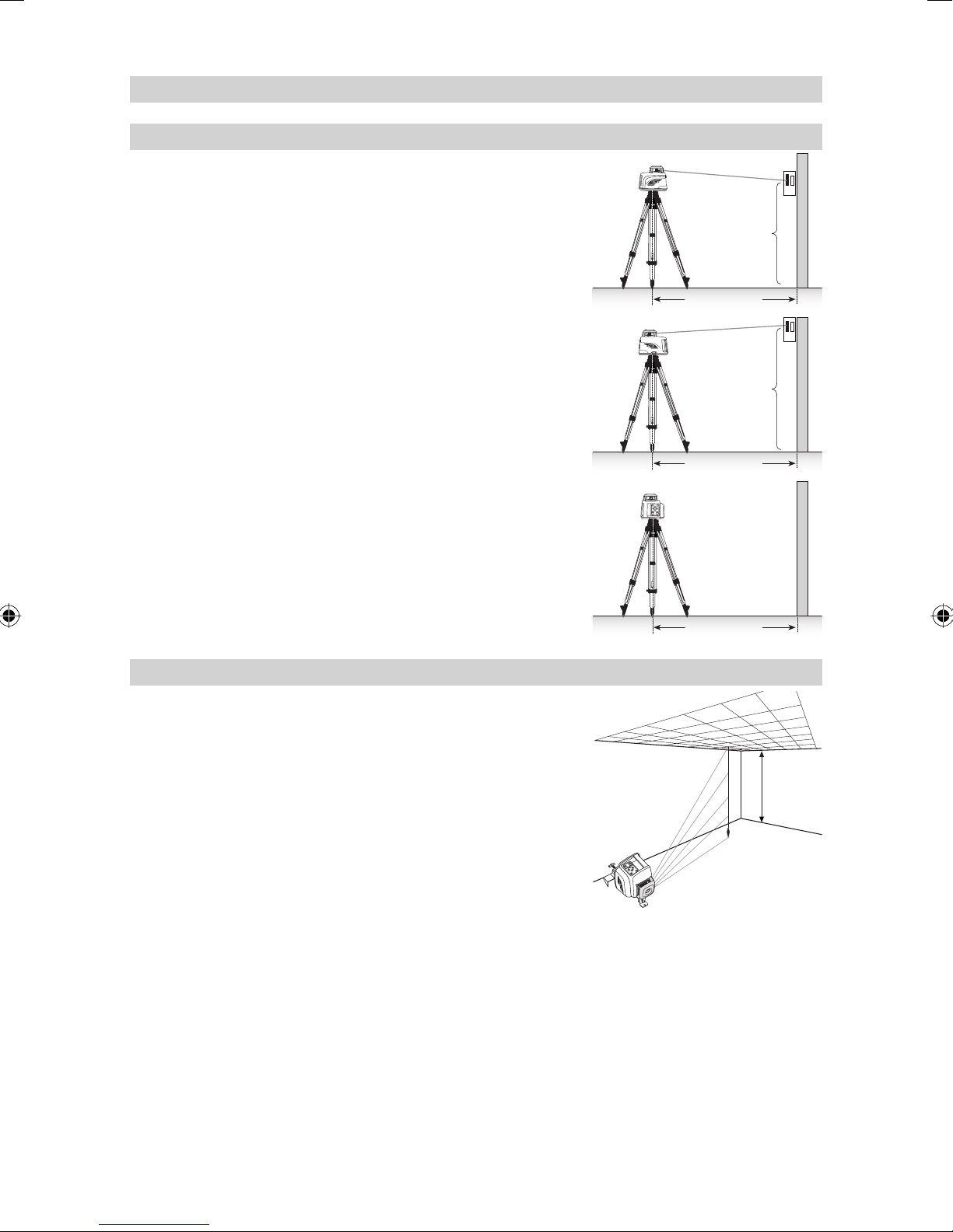
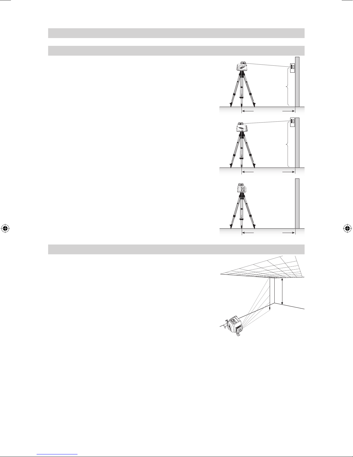
Interior
Acoustical Ceilings
1. Determine and mark the fi nished ceiling height and securely install the fi rst piece of
wall molding to this height.
2. Attach the laser onto the wall molding by sliding the universal mount clamp over the
wall molding and pulling down the locking lever.
3. Make sure the locking knob on the universal mount is loose.
4. T o adjust the elevation, press the quick-release button, slide the laser to the zero (0)
mark on the scale (wall molding elevation), and turn the locking knob to tighten it.
Note: For fi ne height adjustment, turn the T-handle in the direction appropriate
for your adjustment needs.
Note: To minimize accidental dropping, insert a ceiling wire through one of the
safety holes and twist the wire.
Drywall and Partitions
1. Slide the laser along the elevation scale to the top marking notch position.
2. Place the laser over the near wall-control point.
Note: If the universal mount is clamped to the fl oor track, make sure the
laser is set to the edge of the track (“0”).
3. Use the left/right arrow button to point the beam towards the far wall-control
point.
4. Go to the far wall-control point and use the remote control to adjust the line of the
laser until the laser beam is aligned to the mark.
Note: If you’re using the perpendicular beam for alignment, use the left arrow
button to activate the beam plunge function and to move the perpendicular
beam to your far wall-control mark.
Note: When the laser beam is on the mark, use the line buttons for left
and right adjustment.
Note: The laser automatically re-levels 5 seconds after line adjustment
is completed.
5. Install the track or mark the track line on both the fl oor and ceiling for future track
installation.
5 cm (2 in.)
5 cm (2 in.)
9
Page 8
General Construction
C
L
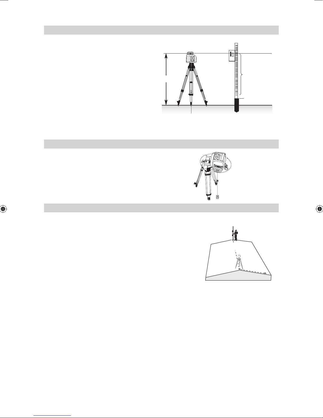
Determining the Height of Instrument (HI)
The height of instrument (HI) is the elevation of the
laser’s beam.
The HI is determined by adding the grade-rod reading
to a benchmark or known elevation.
1. Set up the laser and place the grade rod on a
job-site benchmark (BM) or known elevation.
2. Slide the receiver up/down the grade rod until it
shows an on-grade reading.
3. Add the grade-rod reading to the benchmark to
determine the height of instrument.
Example:
Benchmark = 30.55 m (100.23 ft)
Rod reading = +1.32 m (+4.34 ft)
Height of instrument = 31.87 m (104.57 ft)
Use this HI as a reference for all other elevations.
Establishing Vertical Alignment
1. Mount the universal mount with the attached
laser on a tripod in vertical mode.
2. Stop the rotor if it’s rotating, then use the left/
right arrow button to adjust the rotor vial.
3. Rotate the universal mount on the tripod and
use the T-handle to align the beam to the
reference point.
Height of Instrument (HI)
Rod Reading
HI
HI = Rod Reading + Benchmark
HI = 1,32 m + 30,55 m = 31,87 m (4.34 ft + 100.23 ft = 104.57 ft)
1.32 m (4.34 ft)
Benchmark
30.55 m (100.23 ft)
Using the Y-Axis Single Slope Mode
1. Set up the laser over the reference point (A).
2. Use the sighting guides on the top of the laser to align the laser to
the desired direction hub in the axis that is supposed to be used in
automatic self-leveling mode. Turn the laser on the tripod until it is
properly aligned.
3. Attach a receiver to a grade rod. Set the grade rod on the self-leveling
axis direction hub to check the laser’s elevation (B).
Note: Use this HI as a reference for checking the alignment
of the laser after setting the slope for the other axis.
4. Activate the Y -axis single slope mode by pressing the laser’s manual
button (1 second) after the up arrow button at the laser or remote
control has been pressed and released.
5. Check the laser’s elevation on the slope axis directly in front of the
laser.
6. Set the grade rod on the slope axis direction hub to adjust the laser’s elevation without changing the height
of the receiver on the grade rod (C).
7. Press the up and down arrow buttons until you get an on-grade reading on the receiver.
8. Recheck the laser’s elevation at the automatic self-leveling axis using the HI in step 3.
Note: If the HI has been changed, rotate the laser on the tripod until you get an on-grade reading
again. Make sure, you DON’T change the height of the receiver on the grade rod.
B
A
C
10
Page 9

CALIBRATION
Checking Calibration of the Y- and X-Axes
1. Set up the laser 30 m (100 ft) from a wall and allow it to level.
2. Raise/lower the receiver until you get an on-grade reading for the
+Y axis. Using the on-grade marking notch as a reference, make
a mark on the wall.
Note: For increased precision, use the fi ne-sensitivity
setting (1.5 mm/1/16 in.) on the receiver.
Y+
Y1
30 m (100 ft)
3. Rotate the laser 180° (-Y axis toward the wall) and allow the laser
to re-level.
4. Raise/lower the receiver until you get an on-grade reading for the
–Y axis. Using the on-grade marking notch as a reference, make
a mark on the wall.
5. Measure the difference between the two marks. If they differ
more than 3 mm at 30 m (1/8 inch at 100 feet), the laser needs
calibrating.
6. After checking the Y-axis, rotate the laser 90°. Repeat the above
starting with the + X axis facing the wall.
Z (Vertical) Axis
Checking Calibration of the Z (Vertical) Axis
To check vertical calibration, you need a plumb bob with at least
10 m (30 ft) of string.
1. Suspend the plumb bob from the ceiling of a room whose ceiling
height is at least 10 m (30 ft).
2. Set up the laser in vertical so that the laser beam strikes the top
of the string.
Stop the beam’s rotation.
3. Using the left/right arrow button, guide the beam from the top of
the string to the bottom of it.
4. Look for any deviation in the beam from the top of the string to
the bottom of it.
If the deviation is more than 1 mm (<1/16 in.), the vertical axis
needs calibrating.
Note: If calibration is required, please refer to the calibration instructions on our Trimble website
HYPERLINK “http://www.trimble.com/support.shtml“ www.trimble.com/support.shtml
-Y
30 m (100 ft)
x +
30 m (100 ft)
Y2
10 m
(30 ft)
11
Page 10

M201 UNIVERSAL- MOUNT
0.0
-1
-2
4
3
2
1
13
5
6 7
11
8
10
9
12
14
17
16
15
1. Nail Hole – allows you to hang the uni-mount onto a nail or screw.
2. Locking Lever – opens/closes the clamp.
3. Stop Notches - stops the sliding bracket from moving beyond a set point on the uni-mount. The notches
are positioned so that the center of the beam aligns with the wall molding 0.0 cm (0.0 in.) or 3.1 cm (1
1/4
in.) above it.
4. Index Tab—fi ts into the hole of the L-bracket.
5. Bracket Knob—tightens/loosens the screw that holds the sliding bracket in place after it has been positioned
along the elevation scale.
6. 5/8“ –11 Laser Mount – lets you connect the laser to the uni-mount.
7. L-Bracket – avoids the laser tilting to the right/left when used for wall mount application.
8. Quick-Release Button—lets you move the sliding bracket quickly without having to turn the T-handle.
9. T-Handle—lets you fi ne adjust the laser’s position (1.5 mm [
1/16 in.] per revolution) on the universal mount.
10. Elevation Scale – provides graduated marks that indicate the position of the laser relative to the wall molding
height. The adjustment range on the scale is from 3.1 cm (1
1/4 in.) above wall-molding height to 5 cm
(2 in.) below it. (The “–2“ position is aligned with the horizontal centerline at the ceiling target.)
11. Reading Edge – allows you to adjust the laser position appropriate for your application needs.
12. Sliding-Bracket Jaw—opens/closes so that the universal mount can be clamped to a batterboard when
the laser is being used for vertical applications.
13. Safety Holes (on both sides)—provide a place to tie a safety wire when mounted to a wall.
14. Vertical-Alignment Notch—shows the position of the laser beam when the laser is set up in vertical mode
and is moved up to the top (3.1 cm [1 1/4 in.]) stop.
15. 5/8“-11 Tripod Mount – lets you connect the uni-mount to a standard tripod when using in vertical mode.
16. Lock Nut – lets you adjust the clamping force.
17. Clamp – opens/closes so that the wall mount can be attached to wall molding or fl oor track.
12
Page 11
PROTECTING THE UNIT
Do not expose the unit to extreme temperatures or temperature changes (do not leave inside the car).
The unit is very robust and can resist damage if dropped even from tripod height. Before continuing your work,
always check the leveling accuracy. See Checking Calibration section.
The laser is water proof and can be used indoors and outdoors.
CLEANING AND MAINTENANCE
Dirt and water on the glass parts of laser or prism will influence beam quality and operating range
considerably.
Remove dirt on the housing with a lint-free, warm, wet and smooth cloth. Do not use harsh cleansers or
solvents.
Allow the unit to air dry after cleaning it.
PROTECTING THE ENVIRONMENT
The unit, accessories and packaging ought to be recycled.
This manual is made of non-chlorine recycling paper.
All plastic parts are marked for recycling according to material type.
Do not throw used batteries into the garbage, water or fi re. Remove them in compliance with
environmental requirements.
Notice to Our European Union Customers
For product recycling instructions and more information,
please go to: HYPERLINK “http://www.trimble.com/environment/summary .html“ www .trimble.com/environment/
summary.html
Recycling in Europe
To recycle Trimble WEEE, mail a request for recycling instructions to:
call: +31 497 53 2430, and Trimble Europe BV
ask for the “WEEE associate,” or c/o Menlo Worldwide Logistics
Meerheide 45
5521 DZ Eersel, NL
WARRANTY
According to legal regulations, the warranty-period for this unit is 24 months for material and manufacturing
defaults.
We do not take any liability for damages caused by a non-accurate unit.
Before starting to work, always carry out the Accuracy Check according to the corresponding chapter.
This warranty is no longer valid if the unit is opened or the labels are removed.
13
Page 12

TECHNICAL DATA
Leveling accuracy
1,3
: ± 0.5 mm/10 m, 1/16“ @ 100 ft, 10 arc seconds
Rotation: 4 speed levels appr. 10/50/200/600 rpm
Operational area
1,2
: appr. 300 m (1000 feet) radius with detector
Laser type: red diode laser 635 nm
Laser class: Class 3R, <5mW
Self-leveling range: appr. ± 5°
Leveling time: appr. 30 sec
Leveling indicators: LED fl ashes
1
Laser beam diameter
: appr. 8 mm
Operating range using remote control: Standard - up to 50m (150 ft);
Long range (lens side) - up to 200 m (650 ft)
Power supply: 4 x 1.5V Mono cells type D (LR20)
Battery Life
1
: NiMH: 55 hours; alkaline: 90 hours
Operating temp.: -4°F to 122°F (-20°C to 50°C)
Storage temp.: -4°F to 158°F (-20°C to 70°C)
Dust- and waterproof: IP66
Tripod attachments: 5/8“-11 horizontally and vertically
Weight: 3.1 kg (6.8 lbs)
Low voltage indication: blinking of the battery indicator
Low voltage disconnection: unit shuts off
Size: 8.3L x 7.1W x 7.9T in.
1) at 21° Celsius
2) under optimal atmospheric circumstances
3) along the axis
DECLARATION OF CONFORMITY
We
Trimble Kaiserslautern GmbH
declare under our sole responsibility that the product
HV401
to which this declaration relates is in conformity with the following standards
EN 61000-4-2, 2001; EN 55011, 2003; EN 61000-4-3, 2003
following the provisions of directive Electromagnetic compatibility 89/336/EEC.
The managing director
Electro-Magnetic Compatibility
Declaration of Conformity
This digital apparatus does not exceed the Class B Limits for radio noise for digital apparatus set out in the
Radio Interference Regulations of the Canadian Department of Communications.
This device complies with part 15 off the FCC rules. Operation is subject to the condition that this device does
not cause harmful interference.
Note: The product been tested and found to comply with the limits for a Class B digital device,
pursuant to part 15 of the FCC rules. These limits are designed to provide reasonable protection
against harmful interference in a residential installation. The product generates, uses and can
radiate radio frequency energy and, if not installed and used in accordance with the instructions,
may cause harmful interference to radio or television reception, which can be determined by turning
the product off and on. The user is encouraged to try to eliminate the interference by one or more
of the following measures:
• Reorient or relocate the receiving antenna.
• Increase the separation between the product and the receiver.
• For more information, consult your dealer or an experienced radio/television technician.
Caution: Changes or modifi cations to the product that are not expressly approved by Trimble could
void authority to use the equipment.
14
Page 13
INHALTSVERZEICHNIS
ZU IHRER SICHERHEIT 15
GERÄTEELEMENTE 16
INBETRIEBNAHME 16
Stromversorgung 16
LASERAUFBAU 17
Ein-/Ausschalten des Lasers 17
Standby-Modus 17
Rotationsmodus 17
Lotstrahlabsenkung 18
Punktmodus 18
Scanmodus 18
Manuell-Modus 18
Einachsenneigungsbetrieb (Y- oder X-Achse) 19
ARBEITSBEISPIELE 19
Innnenausbau 19
Abgehängte Decken 19
Trockenbau- und Trennwände 19
Hochbau 20
Bestimmung der Gerätehöhe (HI) 20
Vertikalaufbau 20
Einachsenneigungsbetrieb (Y- Achse) 20
NIVELLIERGENAUIGKEIT 21
Genauigkeitsüberprüfung (Y- und X-Achse) 21
Genauigkeitsüberprüfung (Z-Achse) 21
M201 Universalhalterung 22
GERÄTESCHUTZ 23
REINIGUNG UND PFLEGE 23
UMWELTSCHUTZ 23
GEWÄHRLEISTUNG 23
TECHNISCHE DATEN 24
D
ZU IHRER SICHERHEIT
Sämtliche Anweisungen sind zu lesen um mit dem Gerät gefahrlos und sicher zu arbeiten.
LASERSTRAHLUNG
DIREKTE BESTRAHLUNG
DER AUGEN VERMEIDEN
LASER KLASSE 3R
• Dieses Produkt sollte nur von geschultem Personal bedient werden, um die Bestrahlung durch gefährliches
Laserlicht zu vermeiden.
• Warnschilder am Gerät nicht entfernen!
• Der Laser unterliegt der Klasse 3R (max. 5mW, 600..680 nm; DIN EN 60825-1:2001-11).
• Wegen des gebündelten Strahls auch den Strahlengang in größerer Entfernung beachten und sichern!
• Niemals in den Laser-Strahl blicken oder anderen Personen in die Augen leuchten! Dies gilt auch in größeren
Abständen vom Gerät!
• Gerät immer so aufstellen, daß Personen nicht in Augenhöhe angestrahlt werden (Achtung an T reppen und
bei Refl exionen).
• In Deutschland: Der Anwender muß die BGI 832 (Berufsgenossenschaftliche Information) beachten.
Wenn das Schutzgehäuse für Servicearbeiten entfernt werden muss, darf dies nur von werksgeschultem
Personal durchgeführt werden.
15
Page 14

Vorsicht, wenn andere als die hier angegebenen Bedienungs- oder Justiereinrichtungen benutzt
oder andere Verfahrensweisen ausgeführt werden, kann dies zu gefährlicher Strahlungsexposition
führen.
Hinweis, wird das Gerät nicht entsprechend der Betriebs anleitung des Herstellers benutzt, kann
der vorgesehene Schutz beeinträchtigt sein.
Der HV401 ist ein einfach zu bedienendes, selbstnivellierendes Lasergerät, mit dem eine oder mehrere
Personen genaue horizontale und vertikale Referenz-, 90o-Winkel- sowie Lotpunkt-Übertragungen vornehmen
können.
GERÄTEELEMENTE
1 Ein-Aus-Taste
2 Batterieanzeige
3 Manuell-/Standby-Taste
4 Nivellieranzeige
5 Manuell-/HI-Warnanzeige
6 Pfeiltasten (Auf/Ab)
7 Pfeiltasten (Rechts/Links)
8 Scantaste
9 Drehzahlwahlaste
10 Rotor
11 Laserkopf
12 Achsausrichtungskerben
13 Rotorlibelle
14 Infrarot-Empfänger
15 Empfangslinse für Langstreckenausrichtung
16 Zentriermarkierungen
17 Batterieladebuchse
18 Tragegriff
19 Batteriedeckel
20 5/8“-11 Stativanschlüsse
21 Gummifüße
INBETRIEBNAHME
STROMVERSORGUNG
Batterien
Warnung
Die NiMH-Batterien können geringe Mengen an Schadstoffen enthalten.
Stellen Sie sicher, dass die Batterien vor der erstmaligen Inbetriebnahme und nach längerer
Nichtbenutzung geladen werden.
Verwenden Sie zum Aufladen nur die vorgesehenen Ladegeräte nach den Angaben des
Herstellers.
Die Batterie darf nicht geöffnet, durch V erbrennung entsorgt oder kurzgeschlossen werden. Dabei
besteht Verletzungsgefahr durch das Entzünden, Explodieren, Auslaufen oder Erwärmen der
Batterie.
Beachten Sie die entsprechenden Vorschriften der jeweiligen Länder bei der Entsorgung.
Batterien unzugänglich für Kinder aufbewahren. Bei Verschlucken kein Erbrechen herbeiführen.
Sofort ärztlichen Rat einholen.
Einsetzen der Batterien
Batteriefachdeckel durch 90°-Drehung des Zentralverschlusses abnehmen. Batterien/Akkus ins Batteriefach so
einlegen, daß der Minuskontakt auf den größeren Batteriespiralfedern liegt (Akkus NUR im Akkupaket).
Die NiMH- Batterien nicht aus dem Batteriekäfi g entfernen und NIEMALS Alkalibatterien in diesen
einsetzen.
Deckel aufl egen und mit Zentralverschluß fi xieren.
Bei Verwendung von Alkali-Batterien wird ein Laden durch eine mechanische Sicherung
verhindert. Nur der Original-Akkupack erlaubt ein Laden im Laser. Fremdakkus müssen
extern geladen werden.
16
Page 15

Akkus laden
Der Laser wird mit NiMH-Batterien geliefert.
Einen Hinweis zum Laden bzw. Austausch der Batterien/Akkus gibt die Batterieanzeige 2 zunächst durch
langsames Blinken (3,8 – 4 V). Bei weiterer Entladung (<3,8 V) leuchtet die LED dauerhaft.
Das zugehörige Netzladegerät benötigt etwa 10 Stunden zum Laden von leeren Akkus. Dazu Ladegerätestecker
in die Ladebuchse des Lasers einstecken. Neue bzw. längere Zeit nicht gebrauchte Akkus bringen erst nach
fünf Lade- und Entladezyklen ihre volle Leistung.
Akkus sollten nur geladen werden, wenn die Temperatur zwischen 10° C und 40° C liegt.
Ein Laden bei höheren Temperaturen könnte die Akkus schädigen. Laden bei niedrigeren
T emperaturen verlängert die Ladezeit und verringert die Kapazität, was zu reduzierter Leistung
und zu einer geringeren Lebenserwartung der Akkus führt.
LASERAUFBAU
Laser horizontal (Stativanschluss und 3 Gummipuffer unten!) auf einer stabilen Unterlage oder mittels 5/8“
x 11 Stativanschluss auf einem Stativ oder Säulen-/Wandhalter in der gewünschten Höhe aufstellen. Das
Gerät erkennt selbständig Horizontal- oder Vertikalbetriebsart je nach Lage des Geräts beim Einschalten. Für
Neigungs- oder Achsausrichtungen über lange Distanzen (bis zu 200 m) ist sicherzustellen, dass die Seite
mit der Empfangslinse 15 zum Ausrichtungspunkt zeigt.
Ein-/Ausschalten des Lasers
Drücken der Ein-Aus-Taste 1 schaltet das Gerät ein.
Alle LED-Anzeigen 2, 4, 5 leuchten für 2 Sek. auf.
Der Laser startet immer im automatischen Selbstnivelliermodus.
Das Gerät ist einnivelliert, wenn der Laserstrahl leuchtet und die Nivellieranzeige 4 nicht mehr blinkt. Die
Nivellieranzeige leuchtet für 5 min. dauerhaft, dann zeigt sie durch erneutes Blinken (1x alle 4 Sek.), dass der
Laser im Automatikbetrieb arbeitet.
Nach dem Einschalten des Lasers und dem automatischen Einnivellieren, startet der Laser in der zuletzt
ausgeführten Betriebsart.
Während des Einnivellierens kann sofort die Drehzahl, Scanlinienlänge und –position gewählt werden (Set and
Forget), wobei der Laserstrahl bereits sichtbar ist und dann bis Abschluß der Selbstnivellierung abschaltet.
Steht der Laser mehr als 8 % schief (Selbstnivellierbereich), blinken die Nivellier- und Manuell/HI-Warnanzeige
ständig, gleichzeitig ertönt ein akustisches Warnsignal. Den Laser dann neu ausrichten.
Befi ndet sich der Laser länger als 10 Minuten außerhalb des Selbstnivellierbereichs, wird das Gerät automatisch
ausgeschaltet.
Höhenalarm: Ist der Laser länger als 5 Minuten im horizontalen Modus nivelliert und die Drehzahl
auf 600 min
der Laser gestört wird (z.B. das Stativ angestoßen wird) und sich die Höhe des Laserstrahls bei der
Neunivellierung mehr als 3 mm ändert, schaltet der Höhenalarm den Laser und Rotor aus, und die rote
Manuell-/HI-Warnanzeige 5 blinkt zweimal pro Sekunde (zweifache Geschwindigkeit des manuellen
Betriebs). Zum Löschen des Höhenalarms, den Laser aus- und wieder einschalten. Nachdem sich
der Laser erneut einnivelliert hat, prüfen Sie die ursprüngliche Referenzhöhe.
Zum Ausschalten, Ein/Aus-Taste 1 erneut drücken.
-1
eingestellt, wird der (HI)-Alarm für die Überwachung der Gerätehöhe aktiviert. Wenn
Standby-Modus
Der Standby-Modus ist eine Energiesparfunktion, die die Batteriebetriebsdauer verlängert.
Drücken und halten Sie die Manuelltaste des Lasers oder der Fernbedienung für 3 Sekunden, um den
Standby-Modus zu aktivieren.
Hinweis: Wenn der Standby-Modus aktiviert ist, sind Laserstrahl, Rotor , Selbstnivelliersystem und
LEDs abgeschaltet, der Höhenalarm bleibt jedoch aktiviert.
Die Batterieanzeige-LED blinkt alle 4 Sekunden, um anzuzeigen, dass sich der Laser im Standby-Modus
befi ndet und nicht abgeschaltet ist.
Drücken und halten Sie die Manuelltaste der Fernbedienung für 3 Sekunden, um den Standby-Modus zu
deaktivieren und die volle Betriebsfähigkeit des Lasers wiederherzustellen. Der Laserstrahl und alle anderen
Funktionen sind wieder eingeschaltet.
17
Page 16

Rotationsmodus
Durch Drücken der Drehzahlwahltaste 9 befi ndet sich das Gerät im Rotationsmodus, bzw. stoppt zuerst den
Scanmodus.
Durch weiteres Drücken der Rotationstaste durchläuft der Laser nacheinander die Geschwindigkeiten 0, 10,
50, 200 und 600 min
Der Laser startet immer mit der zuletzt verwendeten Drehzahl.
Nach Wahl von 10 min-1 kann mit den Pfeiltasten Rechts/Links des Lasers oder der Fernbedienung die Drehzahl
stufenlos bis auf 20 min-1 erhöht bzw. auf 5 min-1 gesenkt werden. Mit den Pfeiltasten Auf/Ab kann man die
Linienlänge vergrößern bzw. verkleinern.
Nach Wahl der Drehzahl 50, 200 oder 600 min-1 kann im Horizontal-Automatik- oder Einachsenneigungsbetrieb
mit den Pfeiltasten Rechts/Links des Lasers oder der Fernbedienung die Drehzahl stufenlos erhöht oder
verkleinert werden. Wird die höchste oder niedrigste Drehzahl erreicht, ertönt ein Tonsignal.
Beim Arbeiten mit einem Empfänger empfi ehlt sich die höchste Rotationsgeschwindigkeit (600 min-1).
Hinweis: Die Rotation des Strahls kann auch mit Hilfe der Scantaste gestoppt werden.
-1
, wobei mit 10 min-1, zur besseren Sichtbarkeit, eine kleine Laserlinie umgeführt wird.
Lotstrahlabsenkung
Mit der Lotstrahlabsenkung kann der nichtrotierende Strahl auf eine Bodenmarkierung
abgesenkt werden, wenn der Laser für Vertikalanwendungen eingesetzt wird. Mit
Hilfe der Pfeiltaste Links/Rechts des Lasers oder der Fernbedienung wird der Strahl
abgesenkt bzw. angehoben.
Vergewissern Sie sich, dass der Strahl rotiert.
Drücken und halten Sie die Pfeiltaste Links, um den Strahl auf den Boden
abzusenken.
Verwenden Sie die Pfeiltasten Auf/Ab, um den abgesenkten Strahl nach links oder rechts auf die gewünschte
Bodenmarkierung auszurichten.
Der abgesenkte Strahl bleibt in dieser Position, bis die seitliche Ausrichtung des Strahls abgeschlossen ist,
und kehrt 5 Sekunden, nachdem die letzte Pfeiltaste gedrückt wurde, in seine normale Position zurück.
Punktmodus
Nach Stoppen der Rotation des Laserstrahls im Horizontalbetrieb, wird der Laserpunkt durch Drücken der
Pfeiltasten Rechts/Links schrittweise nach rechts bzw. links rundherum bewegt.
Im Vertikalbetrieb dagegen, kann durch Drücken der Pfeiltasten Rechts/Links der Laserpunkt im/gegen den
Uhrzeigersinn bewegt und die Rotorlibelle ausgerichtet werden, um den Strahl auf den Lotpunkt unterhalb
des Rotors auszurichten.
Bei längerem Halten der Tasten beschleunigt sich die Punktbewegung.
Der Strahl bewegt sich anfänglich im Fein- und nach 4 Sekunden im Grob-Positionierungstempo. Gleichzeitig
mit dem sich ändernden Bewegungstempo blinkt der Laserstrahl anfangs langsam und nach 4 Sekunden
schneller, im gleichen Takt ertönt ein akustisches Signal.
Scanmodus
Durch einmaliges Drücken der Scantaste 8 befi ndet sich das Gerät im Scanmodus, bzw. stoppt zuerst die
Rotation.
Der Laser startet mit einem Öffnungswinkel von ca. 4°. Erneutes kurzes Drücken der Taste verändert die
Linienlänge über ca. 45°, 90°, bis auf 180°.
Mit den Pfeiltasten Rechts/Links kann die Linie nach rechts oder links bewegt werden. Bei längerem Halten
der Tasten beschleunigt sich die Positionierbewegung der Linie.
Im Horizontal-Automatikbetrieb wird durch Drücken und Halten der Pfeiltasten hoch/runter der Scanzonenbereich
bis zu 180° vergrößert bzw. bis zu 0° verkleinert.
Hinweis: Der Scanmodus kann auch durch Drücken der Drehzahlwahltaste 9 gestoppt werden.
Manuellbetrieb
Durch einmaliges kurzes Drücken der Manuelltaste am Laser oder der Fernbedienung kann das Gerät vom
automatischen Selbstnivellierbetrieb in den Manuellbetrieb umgeschaltet werden, was durch Blinken der roten
LED 5 im Sekundentakt signalisiert wird. In dieser Betriebsart kann die Y-Achse durch Drücken der Pfeiltasten
Auf/Ab am Gerät bzw. der Fernbedienung und zusätzlich die X-Achse des Lasers durch Drücken der Pfeiltasten
rechts/links geneigt werden.
Im Vertikalmodus stellen die Pfeiltasten Auf/Ab den Laserstrahl Links/ Rechts zur Achsausrichtung ein. Die
Pfeiltasten Links/Rechts verstellen die Neigung der Laserebene.
Die Manuelltaste erneut drücken, um zum automatischen Selbstnivellierbetrieb zurückzukehren.
18
Page 17
Einachsenneigungsbetrieb (Y- oder X-Achse)
Nachdem am Laser oder der Fernbedienung die Pfeiltaste hoch gedrückt wurde, ist innerhalb 1 Sekunde die
Manuelltaste zu drücken, um den manuellen Neigungsmodus der Y- Achse zu aktivieren.
Gleichzeitiges Blinken der grünen und roten LED 4/5 im Sekundentakt signalisiert den manuellen Y-AchsenNeigungsmodus.
In dieser Betriebsart kann die Y-Achse mit Hilfe der Pfeiltasten „Auf/Ab“ am Gerät oder der Fernbedienung
geneigt werden, während die X-Achse weiterhin im automatischen Horizontalbetrieb arbeitet (z.B. beim Einbau
von geneigten, abgehängten Decken oder Auffahrten).
Um den manuellen Neigungsmodus der X- Achse zu aktivieren, ist, nachdem am Laser oder der Fernbedienung
die Pfeiltaste Rechts gedrückt wurde, innerhalb 1 Sekunde die Manuelltaste zu drücken.
Gleichzeitiges Blinken der grünen und roten LED 4/5 alle 3 Sekunden signalisiert den manuellen X-AchsenNeigungsmodus.
In dieser Betriebsart kann die X-Achse mit Hilfe der Pfeiltasten „Rechts/Links“ am Gerät oder der Fernbedienung
geneigt werden, während die Y-Achse weiterhin im automatischen Horizontalbetrieb arbeitet.
Arbeitet das Gerät mit 600 min
-1
, ist auch die Trittsicherung (Höhenalarm) aktiv.
Erneutes kurzes Drücken der Manuelltaste schaltet das Gerät in den automatischen Selbstnivellierbetrieb
zurück, was durch die grüne LED 4 angezeigt wird.
ARBEITSBEISPIELE
Innenausbau
Abgehängte Decken
1. Bestimmen und markieren Sie die Endhöhe der Decke und befestigen Sie den ersten
Teil des Wandwinkels auf dieser Höhe.
2. Befestigen Sie den Laser auf dem W andwinkel, indem Sie die Universalhalterung auf
den Wandwinkel schieben und den Klemmhebel arretieren.
3. Vergewissern Sie sich, dass der Feststellknopf an der Universalhalterung gelöst ist.
4. Drücken Sie zur Höheneinstellung den Entriegelungsknopf, schieben Sie den Laser
auf die Nullmarkierung (0) der Skala (Höhe des Wandwinkels) und drehen Sie den
Feststellknopf fest.
Hinweis: Drehen Sie zur Feineinstellung der Höhe den T-Handgriff in die für
Ihre Anwendung erforderliche Richtung.
Hinweis: Um ein versehentliches Herunterfallen des Lasers zu verhindern,
führen Sie einen Deckendraht durch eines der Haltelöcher hindurch und
verdrillen Sie diesen.
Trockenbau- und Trennwände
1. Schieben Sie den Laser entlang der Höhenskala bis zur obersten Stellung.
2. Positionieren Sie den Laser auf den ersten Fluchtpunkt.
Hinweis: Ist die Universalhalterung auf die Bodenschiene geklemmt, muss
der Laser auf die Kante der Schiene (“0”-Markierung) eingestellt sein.
3. Positionieren Sie den Strahl mit Hilfe der Pfeiltasten Rechts/Links auf den
gegenüberliegenden Fluchtpunkt.
4. Gehen Sie zum gegenüberliegenden Fluchtpunkt und richten Sie den Laserstrahl
mit Hilfe der Fernbedienung auf die Markierung aus.
Hinweis: Wenn Sie den Lotstrahl zur Ausrichtung einsetzen, verwenden Sie
die Pfeiltaste links, um die Lotstrahlabsenkungsfunktion zu aktivieren und
den abgesenkten Strahl auf den nächsten Fluchtpunkt auszurichten.
Hinweis: Trifft der Laserstrahl auf die Markierung, verwenden Sie die
Richtungstasten zur Achsausrichtung nach links/rechts.
Hinweis: 5 Sekunden nach Beendigung der Richtungseinstellung wird der
Laser automatisch neu nivelliert.
5. Montieren Sie die Bodenschiene oder markieren Sie für weitere Schieneneinbauten
den Schienenverlauf sowohl auf dem Boden als auch an der Decke.
5 cm (2 in.)
5 cm (2 in.)
19
Page 18
Hochbau
C
L
Bestimmung der Gerätehöhe (HI)
Die Gerätehöhe (HI) ist die Höhe des Laserstrahls.
Gerätehöhe (HI)
Sie wird durch die Addition der Meßlattenablesung
zu einer Höhenmarkierung oder einer bekannten
Höhe ermittelt.
Aufbau des Lasers und Positionierung der Messlatte
mit dem Empfänger auf einem bekannten Höhenoder Referenzpfl ock (NN).
HI
Empfänger auf die Position “Auf Höhe” des Laserstrahls ausrichten.
Addieren der Meßlattenablesung zur bekannten NNHöhe, um die Laserhöhe zu ermitteln.
Beispiel:
NN-Höhe = 30,55 m
Lattenablesung = +1,32 m
HI = Lattenablesung + NN-Höhe
HI = 1,32 m + 30,55 m = 31,87 m
Laserhöhe = 31,87 m
Die Laserhöhe als Referenz für alle anderen Höhenmessungen verwenden.
Vertikalaufbau
1. Montieren Sie die Universalhalterung mit dem
darauf angebrachten Laser im Vertikalmodus
auf einem horizontal ausgerichteten Stativ.
2. Stoppen Sie den Rotor und richten Sie die
Rotorlibelle mit Hilfe der Pfeiltasten Rechts/
Links aus.
3. Drehen Sie die Universalhalterung auf dem
Stativ und richten Sie den Strahl mit Hilfe des
T-Handgriffs auf den Referenzpunkt aus.
Lattenablesung
1,32 m
NN-Höhe
30,55 m
Einachsenneigungsbetrieb (Y- Achse)
1. Bauen Sie den Laser über dem Referenzpunkt auf (A).
2. Verwenden Sie die Achsausrichtungskerben am Laserkopf,
um den Laser auf den gewünschten Richtungspflock in der
selbstnivellierenden Achse auszurichten. Drehen Sie den Laser auf
dem Stativ, bis dieser korrekt ausgerichtet ist.
3. Befestigen Sie einen Empfänger an einer Messlatte. Setzen Sie die
Messlatte auf den Richtungspfl ock der selbstnivellierenden Achse,
um die Höhe des Lasers zu überprüfen (B).
Hinweis: Verwenden Sie diese Gerätehöhe als Referenz bei
der Überprüfung der Laserausrichtung nach der Einstellung
der Neigung in der anderen Achse.
4. Nachdem am Laser oder der Fernbedienung die Pfeiltaste Auf
gedrückt wurde, ist innerhalb 1 Sekunde die Manuelltaste zu drücken, um den manuellen Neigungsmodus
der Y- Achse zu aktivieren.
5. Messen Sie direkt am Gerät in der Neigungsachse die Höhe des Laserstrahls.
6. Ohne die Höhe des Empfängers zu verändern, setzen Sie die Messlatte zur Ausrichtung der Neigung auf
den Richtungspfl ock der Neigungsachse (C).
7. Drücken und halten Sie die Pfeiltaste Auf/Ab so lange, bis sich der Empfänger “Auf Höhe” des Laserstrahls
befi ndet.
8. Überprüfen Sie die Höhe des Lasers in der selbstnivellierenden Achse unter Verwendung der Gerätehöhe
in Schritt 3 erneut.
Hinweis: Wenn sich die Gerätehöhe geändert hat, verdrehen Sie den Laser auf dem Stativ so lange,
bis der Empfänger wieder “Auf Höhe” des Laserstrahls anzeigt. Stellen Sie sicher, dass die Höhe
des Empfängers an der Messlatte NICHT verändert wird.
B
A
C
20
Page 19
NIVELLIERGENAUIGKEIT
Überprüfung der Kalibrierung der Y- und X- Achse
1. Stellen Sie den Laser 30 m entfernt von einer Wand auf und lassen
Sie diesen sich horizontal einnivellieren.
2. Bewegen Sie den Empfänger nach oben/unten, bis er sich auf der
+Y Achse “Auf Höhe” des Laserstrahls befi ndet. Verwenden Sie
die Markierungskerbe als Referenz und markieren Sie die Höhe
an der Wand.
Hinweis: Verwenden Sie für eine erhöhte Genauigkeit die
Feineinstellung (1,5 mm) auf dem Empfänger.
3. Drehen Sie den Laser um 180° (die -Y Achse muss zur Wand
zeigen) und lassen Sie ihn sich neu einnivellieren.
4. Bewegen Sie den Empfänger nach oben/unten, bis er sich auf der
-Y Achse “Auf Höhe” des Laserstrahls befi ndet. Verwenden Sie
die Markierungskerbe als Referenz und markieren Sie die Höhe
an der Wand.
5. Messen Sie die Differenz zwischen den beiden Markierungen.
Der Laser muss kalibriert werden, wenn die Differenz bei 30 m
größer als 3 mm ist.
6. Drehen Sie den Laser nach dem Einstellen der Y Achse um 90°.
Wiederholen Sie die Schritte 2-5, wobei Sie mit der zur Wand
zeigenden + X Achse beginnen.
Y+
Y1
30 m (100 ft)
-Y
Y2
30 m (100 ft)
x +
Überprüfung der Kalibrierung der Z- Achse
Zur Überprüfung der vertikalen Kalibrierung benötigen Sie ein Senklot
mit einer mindestens 10 m langen Schnur.
1. Lassen Sie das Senklot von der Decke eines Raumes herunterhängen,
dessen Deckenhöhe mindestens 10 m beträgt.
2. Bauen Sie den Laser vertikal auf, so dass der Laserstrahl das obere
Ende der Schnur trifft. Stoppen Sie die Rotation des Strahls.
3. Führen Sie unter Verwendung der Pfeiltasten Rechts/Links den
Strahl vom oberen zum unteren Ende der Lotschnur.
4. Achten Sie auf Abweichungen des Strahls im Verlauf vom oberen
zum unteren Ende der Lotschnur. Beträgt die Abweichung mehr als
1 mm, muss die vertikale Achse kalibriert werden.
Hinweis: Ist eine Korrektur der Kalibrierung erforderlich,
folgen sie bitte den Kalibrierungsanweisungen auf unserer
Trimble Webseite:
HYPERLINK „http://www.trimble.com/support.shtml“ www.trimble.com/support.shtml
30 m (100 ft)
10 m
(30 ft)
21
Page 20

M201 Universalhalterung
0.0
-1
-2
3
2
1
13
5
6 7
8
9
4
10
11
12
14
17
16
15
1. Nagelloch — ermöglicht das Aufhängen der Universalhalterung an einem Nagel oder einer Schraube.
2. Klemmhebel — zum Öffnen/Schließen der Klemmvorrichtung.
3. Stoppkerben — stoppen die Gleitkonsole an einem Einstellpunkt der Universalhalterung. Die Kerben
stellen sicher, dass der Strahl auf den Wandwinkel (0,0 cm) oder 3,17 cm darüber ausgerichtet ist.
4. Führungsnase — passt in die am L-Winkel befi ndliche Aufnahmeführung.
5. Feststellknopf — zur Arretierung der Gleitkonsole , nachdem diese auf der Höhenskala positioniert
wurde.
6. 5/8“-11 Lasergewinde — zur Befestigung des Lasers auf der Universalhalterung.
7. L-Winkel-verhindert ein seitliches Verkippen des Lasers wenn dieser am Wandwinkel genutzt wird.
8. Entriegelungsknopf — ermöglicht das schnelle Verschieben der Gleitkonsole ohne Drehen des T-
Handgriffs.
9. T-Handgriff — ermöglicht die Feineinstellung der Laserposition (1,5 mm pro Umdrehung) auf der
Universalhalterung.
10. Höhenskala — Skalenmarkierungen, die die Position des Lasers relativ zur Höhe des Wandwinkels
anzeigen. Der Verstellbereich der Skala reicht von 3,1cm oberhalb bis zu 5 cm unterhalb des W andwinkels.
(Die „-2“ Markierung ist auf die horizontale Mittellinie der Deckenzieltafel ausgerichtet.)
11. Ablesekante — ermöglicht die Ausrichtung des Lasers auf die für Ihre Anwendung erforderliche
Skalenposition..
12. Klemmvorrichtung für die Gleitkonsole — zum Festklemmen der Universalhalterung auf einem Schnurgerüst
beim Einsatz des Lasers für Vertikalanwendungen.
13. Haltelöcher (beidseitig) — zum Befestigen eines Sicherheitsdrahts bei Anbringung an einer Wand.
14. Markierungskerbe — zeigt die Position des Laserstrahls an, wenn der Laser im Vertikalmodus aufgebaut
und bis zum oberen Anschlag (3,1 cm) geschoben ist.
15. 5/8“-11 Stativgewinde — zur Anbringung der Universalhalterung auf einem Standardstativ beim Lasereinsatz
im Vertikalmodus.
16. Sicherungsmutter — zur Einstellung der Klemmkraft.
17. Klemmvorrichtung — zur Befestigung der Wandhalterung an Wandwinkeln oder Bodenschienen.
22
Page 21
GERÄTESCHUTZ
Gerät nicht extremen Temperaturen und Temperaturschwankungen aussetzen (nicht im Auto liegen lassen).
Das Gerät ist sehr robust. Trotzdem ist mit Meßgeräten sorgfältig umzugehen. Nach stärkeren äußeren
Einwirkungen, vor weiterem Arbeiten immer die Nivelliergenauigkeit überprüfen.
Das Gerät kann im Innen- und Außenbereich eingesetzt werden.
REINIGUNG UND PFLEGE
Verschmutzungen der Glasfl ächen beeinfl ussen die Strahlqualität und Reichweite
entscheidend.Verschmutzungen mit feuchtem, weichem Tuch abwischen. Keine
scharfen Reinigungs- und Lösemittel verwenden. Nasses Gerät an der Luft trocknen lassen.
UMWELTSCHUTZ
Gerät, Zubehör und Verpackung sollten einer umweltgerechten Wiederverwertung zugeführt werden.
Diese Anleitung ist aus chlorfrei gefertigtem Recycling-Papier hergestellt. Alle Kunststoffteile sind zum
sortenreinen Recycling gekennzeichnet.
Verbrauchte Batterien/Akkus nicht in den Hausmüll, ins Feuer oder ins Wasser werfen,
sondern umweltgerecht entsorgen.
Hinweis für Kunden in der EU
Produktrecycling-Instruktionen und weitere Informationen erhalten sie unter:
HYPERLINK „http://www.trimble.com/environment/summary.html“ www.trimble.com/environment/summary.html
Recycling in Europa:
Zur Wiederverwertung bitte bei Trimble WEEE anrufen:
+31 497 53 2430,
und nach dem “WEEE Partner” fragen.
Oder
Brief mit Anforderung der Recycling- Instruktionen senden an:
Trimble Europe BV
c/o Menlo Worldwide Logistics
Meerheide 45
5521 DZ Eersel, NL
GEWÄHRLEISTUNG
Das Gerät besitzt gemäß der gesetzlichen Bestimmungen 24 Monate Gewährleistung auf Material und
Herstellungsfehler.
Für Schäden, die durch Anwendung eines dejustierten Geräts entstehen, wird keine Haftung übernommen.
Vor Arbeitsbeginn immer Genauigkeitsprüfung gemäß gleichnamigem Abschnitt durchführen.
Die Gewährleistung erlischt mit dem Öffnen des Geräts oder dem Entfernen der Typschilder.
23
Page 22

TECHNISCHE DATEN
Meßgenauigkeit
1,3
: ± 0,5 mm/10 m, 10 arc sec
Rotation: 4 Geschwindigkeiten; typ. 10/50/200/600 min-1.
1,2
Reichweite
: ca. 300 m Radius mit Detektor
Lasertyp: roter Diodenlaser 635 nm
Laserklasse: Laserklasse 3R, <5 mW
Selbstnivellierbereich: typ. ± 5°
Nivellierzeit: typ. 30 sec.
Nivellieranzeige: LED blinkt
1
Strahldurchmesser
: ca. 8mm am Gerät
Reichweite der Fernbedienung: Standard - bis zu 50 m;
Langstrecken (Linsenseite) – bis zu 200 m
Stromversorgung: 4 x 1,5 V Monozellen Typ D (LR 20)
Betriebsdauer
1
: NiMH: 55Std.; Alkali: 90 Std.
Betriebstemperatur: -20°C ... 50°C
Lagertemperatur: -20°C ... 70°C
Stativanschlüsse: 5/8“ horizontal und vertikal
Wasser- und staubgeschützt: IP66
Gewicht: 3,1 kg
Niederspannungsanzeige: Batterieanzeige blinkt/leuchtet
Niederspannungsabschaltung: Gerät schaltet vollständig aus
Abmaße: 21L x 18W x 20H cm
1) bei 21° Celsius
2) bei optimalen atmosphärischen Bedingungen
3) entlang der Achsen
Konformitätserklärung
Wir
Trimble Kaiserslautern GmbH
erklären in alleiniger Verantwortung, daß das Produkt
HV401
auf das sich diese Erklärung bezieht, mit den folgenden Normen übereinstimmt
EN 61000-4-2, 2001; EN 55011, 2003; EN 61000-4-3, 2003
gemäß den Bestimmungen der Richtlinie
Electromagnetic compatibility 89/336/EEC.
Kaiserslautern, 17.05.2005
Bernd Brieger, Geschäftsführer
24
Page 23

SOMMAIRE
POUR VOTRE SECURITE 25
ELEMENTS DE L’APPAREIL 26
MISE EN SERVICE 26
Alimentation en courant 26
Mise en place du laser 27
Marche/arrêt du laser 27
Mode veille 27
Mode de rotation 27
Faire incliner le faisceau 28
Mode de point 28
Mode de ligne 28
Mode manuel 28
Mode de nivellement à un axe (Y ou X) 29
EXEMPLES DE TRAVAIL 29
I’intérieur 29
Plafonds acoustiques 29
Cloison sèche et cloisons 29
Construction générale 30
Détermination de la hauteur d’instrument (HI) 30
Installation verticale 30
Mode de nivellement à un axe (Y) 30
PRECISION DE NIVELLEMENT 31
Contrôle de la précision (Y ou X) 31
Contrôle de la précision (Z) 31
M201 Platine de fi xation universelle 32
PROTECTION DE L’APPAREIL 33
NETTOYAGE ET ENTRETIEN 33
PROTECTION DE L’ENVIRONNEMENT 33
GARANTIE 33
CARACTERISTIQUES TECHNIQUES 34
F
POUR VOTRE SECURITE
RAYONNEMENT LASER
NE PAS REGARDER DANS LE
FAISCEAU APPAREIL
A LASER DE CLASSE 3R
• Ne pas retirer les plaques d’avertissement de l’appareil !
• Le faisceau laser est de catégorie 3R (max. 5mW, 600..680 nm; DIN EN 60825-1:2001-11).
• En raison du faisceau, tenir également compte du trajectoire de faisceau à plus grande distance et le protéger !
• Ne regarder jamais dans le faisceau laser ou le diriger dans les yeux d’autres personnes ! Ceci s’applique
également aux plus grandes distances par rapport à l’appareil !
• Installer l’appareil toujours de sorte que les personnes ne sont pas exposées au faisceau au niveau des
yeux (attention aux escaliers et en cas de réfl exions).
25
Page 24

ELEMENTS DE L’APPAREIL
1 Touche marche/arrêt
2 Indicateur de pile
3 Touche Manuel / veille
4 Indicateur de service/de nivellement
5 Indicateur manuel/(HI) d’avertissement
6 Touche à fl èche haut/bas
7 Touche à fl èche droite/gauche
8 Touche de ligne
9 Touche de vitesse et de rotation
10 Rotor
11 Tête de laser
12 Repères d’alignement des axes
13 Nivelle de rotor
14 Récepteur à infrarouge pour la télécommande
15 Lentille de réception pour ajustement longue portée
16 Marquages de centrage
17 Prise de chargement batterie
18 Poignée
19 Couvercle de pile
20 5/8“-11 Raccords de pied
21 Pieds en caoutchouc
MISE EN SERVICE
Alimentation en courant
Batteries
Avertissement
Les batteries NiMH peuvent contenir de faibles quantités de substances nocives.
Assurez-vous de charger les batteries avant la première mise en service et après une longue durée
de non-utilisation.
Utilisez uniquement les chargeurs prévus pour la recharge conformément aux indications du
fabricant.
La batterie ne doit pas être ouverte, ni éliminée par combustion, ni court-circuitée. Il existe un
risque de blessures causées par l’infl ammation, l’explosion, l’écoulement ou le réchauffement de
la batterie.
Respectez les prescriptions correspondantes des pays respectifs pour l’élimination.
Conserver les batteries hors de portée des enfants. En cas d’absorption, ne pas provoquer de
vomissements.
Consulter immédiatement un médecin.
Introduction des piles/accumulateurs
Retirer le couvercle du compartiment de piles en tournant la fermeture centrale de 90°. Introduire les piles/
accumulateurs dans le compartiment de manière à ce que le contact négatif se trouve sur les ressorts
spiralés des piles et les fi xer par la fermeture centrale.
En cas de piles alcalines, un chargement est empêché par une protection mécanique.
Seul l’ensemble d’accumulateurs d’origine permet le chargement dans l’appareil. Les
accumulateurs d’autres marques doivent être chargés de façon externe.
Chargement des accumulateurs
Le laser est livré avec des batteries NiMH.
Le fait que les piles/accumulateurs doivent être chargés ou remplacés est signalé par l’indicateur 2 en clignotant
d’abord lentement (3,8 – 4 V). Lorsque le déchargement se poursuit, le témoin lumineux est constamment
allumée avant que l’appareil s’arrête complètement (<3,8 V).
L’appareil de chargement nécessite 10 heures environ pour charger les accumulateurs vides. Pour cela, enfi cher
la fi che de l’appareil de chargement dans la prise de chargement de l’appareil. La fonction de chargement est
indiquée par l’indicateur rouge sur l’appareil de chargement à fi che. Les accumulateurs neufs ou pas utilisés
26
Page 25

pendant une période prolongée n’obtiennent leur puissance complète qu’après cinq cycles de chargement
et de déchargement.
Les accumulateurs ne devraient être chargés que lorsque la température de l’appareil se situe
entre 10°C et 40°C. Le chargement à des températures plus élevées risquerait d’endommager
les accumulateurs. Le chargement à des températures plus basses prolonge le temps de
chargement et réduit la capacité, ce qui donne lieu à une puissance réduite et une durée de
vie réduite des accumulateurs.
Mise en place du laser
Placer l’appareil horizontalement ou verticalement sur un support stable ou, au moyen d’un raccord de pied,
sur un pied ou sur une fi xation murale à la hauteur souhaitée. L’appareil reconnaît automatiquement le mode
horizontal ou vertical en fonction de la position de l’appareil lors de la mise en circuit.
Pour des ajustements d’inclinaison ou d’axe sur des distances importantes (jusqu’à 200 m), il est nécessaire
de s’assurer que la face de la lentille de réception 15 est dirigée vers le point d’ajustement.
Marche/arrêt du laser
En appuyant sur la touche marche/arrêt 1, l’appareil est mis en marche et tous les indicateurs lumineux 2,
4, 5 s’allument pendant 2 secondes. Le nivellement commence immédiatement. Pour la mise hors service,
réappuyer sur la touche. Pendant le nivellement, le rotor est arrêté, l’indicateur de nivellement 4 clignote (1
x par sec.). L’appareil est nivelé lorsque le faisceau laser est allumé et que l’indicateur de nivellement 4 ne
clignote plus. L’indicateur de nivellement est allumé en permanence pendant 5 min., ensuite, son clignotement
(1x toutes les 4 sec.) indique que le laser fonctionne en mode automatique.
Après la mise en circuit du laser et le nivellement automatique, le laser démarre dans le dernier mode de
fonctionnement exécuté. La vitesse de rotation, la longueur de la ligne et la position de balayage peuvent être
sélectionnées lors du nivellement (Set and Forget), où le faisceau laser est déjà visible et est coupé jusqu’au
terme de l’auto-nivellement.
Lorsque l’appareil est incliné de plus de 8% (gamme de nivellement automatique), le laser et les indicateurs
de nivellement clignotent toutes les secondes. L’appareil doit alors être réajusté.
Si le laser se situe hors de la plage d’auto-nivellement pendant plus de 10 minutes, l’appareil est stoppé
automatiquement.
Remarque : Après que le laser ait été à niveau pendant plus de 5 minutes en mode horizontal et
que le rotor tourne à 600 tr/mn, l’alerte HI est activée. Si le laser est perturbé (choc sur le trépied,
etc.) de telle sorte que lorsqu’il procède à son auto-nivellement, l’élévation du faisceau laser se
soit modifi ée de plus de 3 mm (1/8 inch), l’alerte HI coupe le laser et le rotor , et le témoin lumineux
rouge clignote deux fois par seconde (le double de la cadence dans le mode manuel). Pour rétablir
le niveau, mettez le laser hors tension puis remettez-le sous tension. Après re-nivellement du laser,
contrôlez votre élévation de référence initiale.
Mode veille
Le mode veille est une fonctionnalité permettant d’économiser l’énergie qui prolonge la durée de vie des
batteries du laser.
Pressez le bouton manuel de la l’appareil ou la télécommande et maintenez-le pressé pendant 3 secondes
pour activer le mode veille.
Remarque : Lorsque le mode veille est activé, le faisceau laser, le rotor , le système d’auto-nivellement
et les témoins lumineux se coupent, mais l’alerte HI reste activée.
Pour vous informer que le laser se trouve en mode veille et non hors tension, le témoin lumineux vert supérieur
des témoins lumineux indicateurs de l’état des batteries clignote une fois 4 secondes.
Pour désactiver le mode veille et retrouver toutes les fonctionnalités du laser, pressez le bouton manuel de la
l’appareil ou la télécommande et maintenez-le pressé pendant 3 secondes. Le laser re-fonctionne et toutes
les fonctions du laser redeviennent actives.
Mode de rotation
En appuyant sur la touche de rotation/de vitesse 9, l’appareil se trouve en mode de rotation ou il arrête d’abord
le mode de ligne.
En réappuyant sur la touche de rotation, le laser parcourt l’une après l’autre les vitesses 0, 10, 200, et 600
min-1, avec 10 min-1, une petite ligne de laser est réalisée pour obtenir une meilleure visibilité.
Le laser démarre toujours à la vitesse utilisée lors du dernier fonctionnement.
Après avoir sélectionné 10 min-1, la vitesse peut être augmentée jusqu‘à 20 min-1 ou abaissée en continu jusqu’à
27
Page 26

5 min-1 à l’aide des touches du laser ou de la télécommande. Les touches haut/bas permettent d’augmenter
ou baisser la longueur de ligne.
Après avoir sélectionné une vitesse de 50, 200 ou 600 min
continu en fonctionnement automatique horizontal ou inclinaison un axe à l’aide des touches gauche/droite
du laser ou de la télécommande. Lorsque la vitesse la plus élevée ou la plus faible est atteinte, une tonalité
est émise.
Lors du travail avec un récepteur, il est recommandé d’utiliser la vitesse de rotation la plus élevée.
Remarque : On peut employer la touche de balayage de zone pour arrêter la rotation du
faisceau.
-1
, la vitesse peut être augmentée ou baissée en
Faire incliner le faisceau
Remarque : pour faire incliner le faisceau perpendiculairement (non
tournant) vers un repère sur le sol lorsqu’on emploie le laser pour des
applications verticales, pressez la touche mentionnant la fl èche vers la
gauche pour incliner le faisceau, et la touche mentionnant la fl èche vers la
droite pour le faire monter.
Veuillez vous assurer que le faisceau soit actif.
Pressez la touche mentionnant la fl èche vers la gauche et maintenez-la pressée pour faire incliner le faisceau
vers le sol.
Employez les boutons mentionnant la fl èche vers la gauche et vers la droite pour incliner le faisceau sur le
repère du sol souhaité.
Remarque : Le faisceau reste dirigé vers le bas jusqu’à l’achèvement de l’ajustement d’alignement
du faisceau perpendiculaire, puis à ce moment-là il reprend sa position normale, 5 secondes après
avoir actionner cette fonction.
Mode de point
Après l’arrêt de la rotation du faisceau laser en fonctionnement horizontal, le point laser peut être déplacé pas
à pas vers la gauche ou la droite à l’aide des touches gauche/droite.
En fonctionnement vertical par contre, le point laser peut être déplacé dans le sens des aiguilles d’une montre
et inversement à l’aide des touches gauche/droite, et le niveau du rotor peut être ajusté de manière à diriger
le faisceau sur le point de perpendicularité sous le rotor.
Un appui prolongé sur les touches provoque une accélération du mouvement du point.
Le faisceau se déplace lentement pendant les 4 premières secondes, puis au rythme de positionnement
approximatif. En parallèle, le faisceau laser clignote d‘abord lentement puis plus rapidement après 4 secondes
et une tonalité est émise.
Mode de ligne
En appuyant une fois sur la touche de ligne 8, l’appareil se trouve en mode de ligne ou il arrête d’abord la
rotation.
Le laser commence par un angle d’ouverture de 4°. En ré- appuyant sur la touche, la longueur de ligne
change via 45°, 90° jusqu’à 180°. Les touches mentionnant la fl èche droite/gauche permettent de déplacer
la ligne vers la droite ou vers la gauche. Lorsque les touches sont maintenues pressées, le mouvement de
positionnement de la ligne est accéléré.
En fonctionnement automatique horizontal, l’appui et le maintien des touches haut/bas provoque une
augmentation à 180° ou une diminution à 0° de l’angle de balayage.
Remarque : On peut employer la touche de commande de rotation pour arrêter le mode de
balayage.
Mode manuel
La l’appareil ou la télécommande permet de commuter l’appareil du mode de nivellement automatique au mode
manuel en appuyant une fois brièvement sur la touche manuelle, ce qui est signalé par le clignotement de la
diode lumineuse rouge 5 toutes les secondes. Dans ce mode de fonctionnement, il est possible d’incliner l’axe
Y en actionnant les touches mentionnant la fl èche « vers le haut/bas » sur l’appareil ou la télécommande et en
plus l’axe X du laser en actionnant les touches mentionnant la fl èche « vers la droite/gauche ».
Remarque : Dans le mode vertical, les boutons mentionnant les fl èches vers le haut et vers le bas
ajustent le faisceau laser vers la gauche et vers la droite par rapport à la direction de ligne; les boutons
mentionnant les fl èches vers la gauche et vers la droite ajustent la pente du faisceau laser.
Pour repasser en mode de nivellement automatique, pressez à nouveau sur la touche mode manuel.
28
Page 27

Mode de nivellement à un axe (Y ou X)
Pour enclencher le mode nivellement manuel à un axe Y, la touche manuelle doit être appuyée dans la
seconde suivant un appui sur la touche haut du laser ou de la télécommande ; ce qui est signalisé par le
clignotement simultané des diodes lumineuses verte et rouge 4/5 toutes les secondes. Dans ce mode de
fonctionnement, l’axe Y peut être incliné à l’aide des touches indiquant la fl èche „vers le haut/bas“ sur l’appareil
ou la télécommande alors que l’axe X continue à travailler dans le mode horizontal automatique (p. ex. lors du
montage de plafonds suspendus inclinés ou rampes d’accès). Pour enclencher le mode nivellement manuel
à un axe X, la touche manuelle doit être appuyée dans la seconde suivant un appui sur la touche droite du
laser ou de la télécommande ; ce qui est signalisé par le clignotement simultané des diodes lumineuses verte
et rouge 4/5 toutes les 3 secondes. Dans ce mode de fonctionnement, l’axe X peut être incliné à l’aide des
touches indiquant la fl èche « vers la droite/gauche », sur l’appareil ou la télécommande alors que l’axe Y
continue à travailler dans le mode horizontal automatique
Lorsque l’appareil travaille avec 600 min
-1
, la sécurité de marche est active.
En réappuyant brièvement sur la touche manuelle, l’appareil retourne au mode de nivellement automatique,
ce qui est signalé par la diode lumineuse verte 4.
EXEMPLES DE TRAVAIL
I’intérieur
Plafonds acoustiques
1. Déterminez et marquez la hauteur de plafond terminée et installez de manière sûre le premier morceau de
cornière de mur à cette hauteur.
2. Fixez le laser sur la cornière du mur en faisant glisser la bride de serrage de la platine
de fi xation universelle sur la cornière de mur et en tirant le levier de verrouillage vers
le bas.
3. Assurez-vous que la molette de verrouillage sur la platine universelle est desserrée.
4. Pour ajuster l’élévation, pressez sur la fonction à desserrage rapide, faites glisser le
laser vers le repère zéro (0) sur l’échelle (élévation de la cornière de mur), et tournez
la molette de verrouillage pour le serrer.
Remarque : Pour un ajustement fi n en hauteur, tournez la poignée T dans la
direction convenant aux besoins de votre ajustement.
Remarque : Pour minimiser le risque d’une chute accidentelle, insérez un
fi l provenant du plafond à travers un des espacements de sécurité et nouez
le fi l.
Cloison sèche et cloisons
1. Faîtes glisser le laser le long de l’échelle d’élévation jusqu’à la position de la butée supérieure.
2. Placez le laser au-dessus du point de contrôle mural proche.
Remarque : Si l’on fi xe la platine de fi xation universelle sur la coulisse de sol,
assurez-vous que le laser est réglé sur le bord de la coulisse (échelle “0”).
3. Utilisez les touches indiquant la fl èche «droite/gauche », vers le point de contrôle
du mur éloigné.
4. Déplacez-vous vers le point de contrôle du mur éloigné et utilisez la télécommande
pour ajuster la ligne du laser jusqu’à ce que le faisceau laser soit aligné sur la
marque.
Remarque : Si vous utilisez le faisceau perpendiculaire pour l’alignement,
utilisez la touche indiquant la fl èche vers la gauche pour actionner la fonction
d’abaissement du faisceau et pour déplacer le faisceau perpendiculaire
vers votre repère de contrôle du mur éloigné.
Remarque : Lorsque le faisceau laser est sur le repère, utilisez les boutons
de ligne pour un ajustement à gauche et à droite.
Remarque : Le laser se remet automatiquement à niveau 5 secondes après
achèvement de l’ajustement de ligne.
5. Installez la coulisse ou marquez la ligne de la coulisse à la fois sur le sol et le
plafond pour une installation de coulisse ultérieurement.
5 cm (2 in.)
5 cm (2 in.)
29
Page 28
Construction générale
C
L
Détermination de la hauteur d’instrument (HI)
La hauteur de l’appareil (HI) est la hauteur du
Hauteur de l´appareil (HI)
faisceau laser. Elle est déterminée en ajoutant la
lecture des règles d’appareil à un signe marquant la
hauteur ou à une hauteur connue.
Mise en place du laser et positionnement de la mire
avec le récepteur sur un point de référence ou une
hauteur connue (NN).
HI
Aligner le récepteur sur la position « A hauteur » du
faisceau laser.
Additionner la lecture de hauteur de mire à la hauteur
du point de référence connu NN afi n de déterminer
la hauteur du laser.
HI = Lecture de la règle + NN-Hauteur
Exemple :
HI = 1,32 m + 30,55 m = 31,87 m
Hauteur NN = 30,55 m
Lecture de la Mire = +1,32 m
Hauteur du laser = 31,87 m
Utiliser la hauteur du laser comme référence pour toutes les autres mesures de hauteur.
Installation verticale
1. Montez la platine de fi xation universelle avec le
laser fi xé sur un trépied en mode vertical.
2. Arrêtez le rotor s’il tourne, puis employez les
touches indiquant la fl èche «droite/gauche » pour
ajuster la nivelle du rotor.
3. Faites tourner la platine de fi xation universelle
sur le trépied et employez la poignée en T pour
aligner le faisceau sur le point de contrôle.
Lecture de la règle
1,32 m
NN-Hauteur
30,55 m
Mode de nivellement à un axe (Y)
1. Installez le laser sur le point de référence (A).
2. Utilisez les guides de visée au sommet du laser pour aligner le laser
sur la mire de direction souhaitée dans l’axe dont on suppose une
utilisation en mode nivellement automatique. Tournez le laser sur
le trépied jusqu’à ce qu’il soit aligné correctement.
3. Fixez un récepteur à une mire. Placez la mire sur la visée
directionnelle de l’axe d’auto-nivellement afi n de contrôler l’élévation
du laser (B).
Remarque : Employez cette HI comme référence pour
contrôler l’alignement du laser après avoir défi ni la pente
pour l’autre axe.
4. Pour enclencher le mode nivellement manuel à un axe Y , la touche
manuelle doit être appuyée dans la seconde suivant un appui sur la touche haute du laser ou de la
télécommande ;
5. Mesurez la hauteur du faisceau laser directement à l’appareil en prenant l’axe d’inclinaison.
6. Sans modifi er la hauteur du récepteur, placez la mire graduée en direction de l’inclinaison sur le piquet de
direction de l‘axe d’inclinaison (C).
7. Pressez sur le bouton indiquant la fl èche vers le haut et vers le bas du laser jusqu’à obtenir une lecture à
la cote sur le récepteur.
8. Contrôlez à nouveau l’élévation du laser dans l’axe nivellement automatique en employant la HI dans l’étape 3.
Remarque : Si la HI n’a pas changée, faites tourner le laser jusqu’à obtenir une nouvelle lecture à
la cote. Veillez à NE PAS modifi er la hauteur du récepteur sur la mire.
B
A
C
30
Page 29
PRECISION DE NIVELLEMENT
Contrôle de la précision (Y ou X)
1. Installez et mettez le laser à niveau à 30 m d’un mur.
2. Elevez/abaissez le récepteur jusqu’à ce que vous obteniez une
lecture à la côte pour l’axe +Y. En utilisant la rainure marquant la
mise à la côte comme référence, faites une marque sur le mur.
Remarque : Pour augmenter la précision, utilisez le réglage
fi n (1,5 mm) sur le récepteur.
3. Faites tourner le laser de 180° (l’axe –Y vers le mur) et laissez le
laser procéder à son nivellement automatique.
4. Elevez/abaissez le récepteur jusqu’à obtenir une lecture à la cote
pour l’axe –Y. En utilisant la rainure marquant la mise à la côte
comme référence, faites une marque sur le mur.
5. Mesurez la différence entre les deux marques. Si elles diffèrent
de plus de 3 mm à 30 m, le laser doit être étalonné.
Y+
Y1
30 m (100 ft)
-Y
Y2
6. Après ajustement de l’axe, faites tourner le laser de 90°. Répétez
les étapes 2 à 5 en commençant avec l’axe +X en face du mur.
Contrôle de la précision (Z)
Pour vérifi er un étalonnage vertical, il vous faut un fi l à plomb avec au
moins 10 m de fi celle.
1. Suspendez le fi l à plomb du plafond d’une pièce dont la hauteur est
d’au moins 10 m (30 ft).
2. Installez le laser à la verticale pour que le faisceau laser trace le
haut de la fi celle. Arrêtez la rotation du faisceau.
3. En utilisant le bouton de commande de pointage, guidez le faisceau
du haut de la fi celle vers la partie inférieure de celle-ci.
4. Recherchez tout écart à partir du faisceau du haut de la fi celle jusqu’à
la partie inférieure de celle-ci. Si l’écart est supérieur à 1 mm, l’axe
vertical doit être étalonné.
30 m (100 ft)
x +
30 m (100 ft)
10 m
(30 ft)
31
Page 30
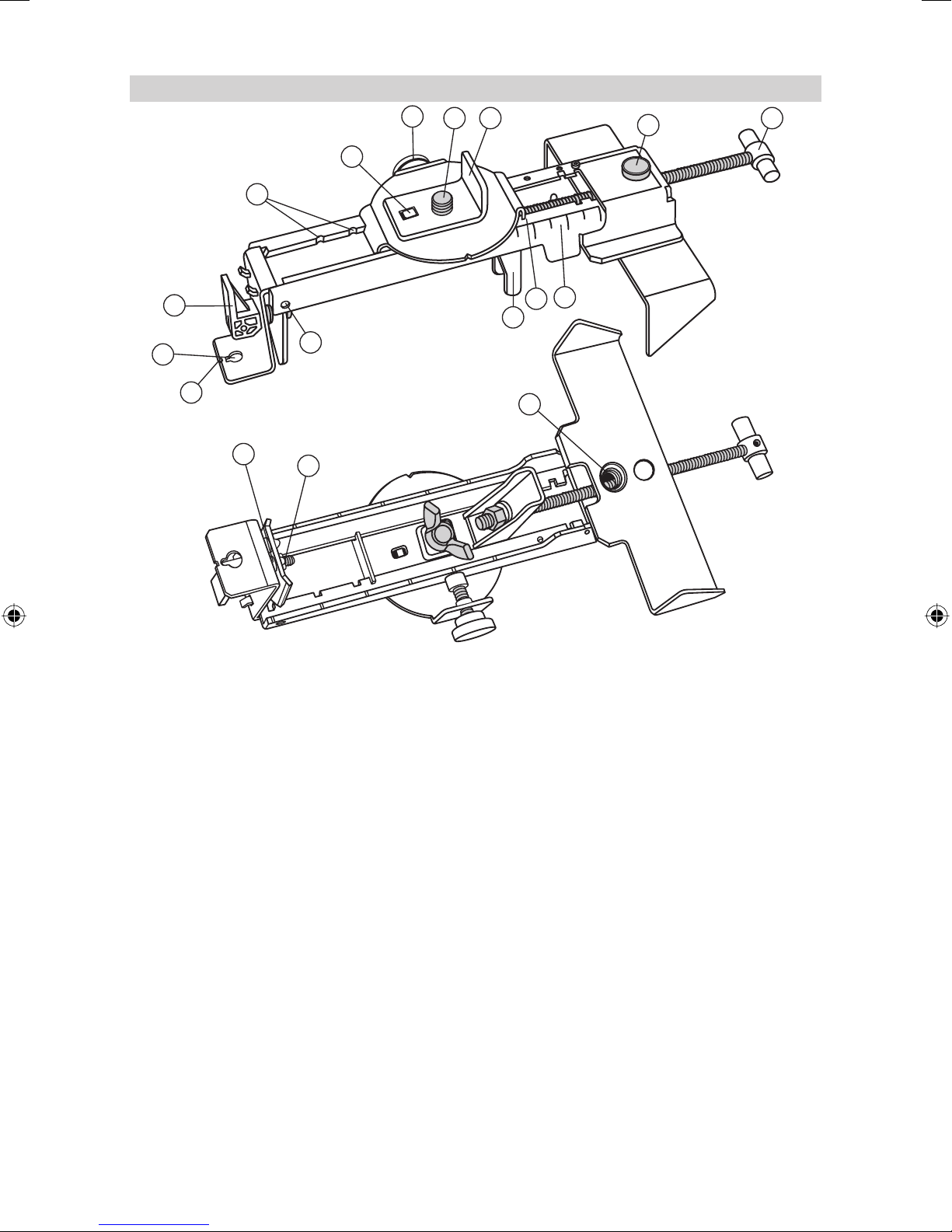
M201 Platine de fi xation universelle
0.0
-1
-2
4
3
2
1
13
5
6 7
11
8
10
9
12
14
17
16
15
1. Trou de clou — permet de suspendre la fi xation universelle par un clou ou une vis.
2. Levier de serrage — pour ouvrir/ferme ce dispositif de serrage.
3. Repères d’arrêt — arrête la console glissant à un point de réglage de la fi xation universelle. Les encoches
assurent que le faisceau est dirigé vers l’angle mural (0,0 cm) ou (3,1 cm).
4. Bec de direction - s‘adapte à l‘angle L se trouvant dans l‘ensemble de direction de captage.
5. Fonction de la bride—serre/desserre la vis qui maintient la vis coulissante en place après l’avoir disposée
le long de l’échelle d’élévation.
6. Filetage de fi xation du laser 5/8“-11 — pour fi xer le laser sur la fi xation universelle.
7. L’angle L empêche tout défaut d’alignement latéral du laser lorsqu’il est utilisé à l’angle mural.
8. Bouton de desserrage rapide—permet de déplacer la bride coulissante rapidement sans avoir à tourner
la poignée en T.
9. Poignée en T—permet d’ajuster finement la position du laser (1,5 mm par tour) sur la fixation
universelle.
10. Echelle de hauteur – marquages d’échelle qui indiquent la position du laser par rapport à la hauteur de
l’équerre de mur. La plage de réglage de l’échelle va de 3,1cm au-dessus jusqu’à 5 cm en dessous de
l’équerre de mur. (Le marquage « -2 » est orienté vers la ligne centrale horizontale du tableau de plafond
de destination.)
11. Arête de lecture — permet d’ajuster le laser à la position d’échelle requise pour votre application.
12. Fixation—s’ouvre/se ferme de manière à maintenir la fi xation universelle à une cornière de rive ou à un
rail de guidage au sol.
13. Trous de sécurité (des deux côtés) — offre un emplacement pour attacher un fi l de sécurité lorsqu’on la
monte sur un mur.
14. Repère d’alignement vertical—indique la position du faisceau laser lorsque le laser est installé en mode
vertical et qu’on le déplace vers la butée du haut (3,1 cm).
15. Filet de pied 5/8“-11 — pour fi xer la fi xation universelle sur un pied standard en cas d’utilisation du laser
en mode vertical.
16. Ecrou de sûreté — pour le réglage de la force de réglage.
17. Fixation—s’ouvre/se ferme de manière à maintenir la fi xation universelle à une cornière de rive ou à un
rail de guidage au sol.
32
Page 31

PROTECTION DE L’APPAREIL
Ne pas soumettre l’appareil aux températures extrêmes et aux fl uctuations de température (ne pas laisser
dans la voiture).
L’appareil est très robuste. Malgré tout, il faut traiter les appareils de mesure très soigneusement. Après de
fortes infl uences extérieures, il faut toujours contrôler la prévision de nivellement avant tout travail.
L’appareil peut être utilisé à l’intérieur et à l’extérieur.
NETTOYAGE ET ENTRETIEN
Les encrassements des surfaces en verre infl uencent la qualité du faisceau et la porté de manière décisive.
Essuyer les encrassements au moyen d’un chiffon doux et humide. Ne pas utiliser de produits de nettoyage
et de solvants agressifs. Laisser sécher l’appareil mouillé à l’air.
PROTECTION DE L’ENVIRONNEMENT
L’appareil, les accessoires et l’emballage devraient être recyclés de façon écologique.
Ce mode d’emploi est imprimé sur du papier de recyclage sans chlore. T ous les éléments en matière plastique
sont marqués pour un recyclage selon les sortes.
Les piles/accumulateurs usés ne doivent pas être jetés avec les ordures ménagères, jetés
dans le feu ou dans l’eau, mais éliminés de façon écologique.
Notifi cation aux clients Européens
Pour les informations concernant le recyclage du produit, Veuillez visiter:
HYPERLINK „http://www.trimble.com/environment/summary.html“ www.trimble.com/environment/summary.html
Recyclage en Europe
Pour le recyclage de WEEE Trimble,
Appelez au +31 497 53 2430,
et demandez le “le responsable WEEE,”
ou
Expédiez une demande pour les instructions de recyclage à:
Trimble Europe BV
c/o Menlo Worldwide Logistics
Meerheide 45
5521 DZ Eersel, NL
GARANTIE
L’appareil a une garantie de 24 mois conforme aux dispositions légales pour le matériel et les défauts de
fabrication.
Pour les dommages dus à l’utilisation d’un appareil non ajusté, nous n’assumons pas la responsabilité.
Avant de commencer le travail, il faut toujours contrôler la précision conformément au paragraphe
correspondant.
La garantie ne s’applique pas dès que l’appareil est ouvert ou que les plaques signalétiques sont enlevées.
33
Page 32

CARACTERISTIQUES TECHNIQUES
Précision de mesure1,3 : ± 0,5 mm/10 m; 10 arc sec
Rotation: 4 vitesses ; typ. 10/50/200/600 min-1.
Portée1 : 300 m env. de rayon avec détecteur
Type de laser : laser à diode rouge 635 nm
Puissance de laser : <5 mW, catégorie de laser 3R
Plage de nivellement automatique : typ. ± 8 % (± 4,8° env.)
Temps de nivellement : typ. 30 sec.
Indicateur de nivellement : DEL clignote
Diamètre de faisceau1 : 8mm env. sur l’appareil
Portée de la télécommande : habituellement jusqu’à 50 m ;
longue portée (face lentille) – jusqu’à 200 m.
Alimentation en courant : 4 x 1,5 V piles rondes type D (LR 20)
Température de service : - 20°C ... + 50°C
Température de stockage : - 20°C ... + 70°C
Raccords de pied : 5/8“ horizontal et vertical
Poids : 3,1 kg
Indicateur de basse tension : indicateur de pile clignote/est allumé
Arrêt de la basse tension : l’appareil s’arrête complètement
1) à 21° Celsius
2) dans des conditions atmosphériques optimales
3) le long des axes
Déclaration de conformité
Nous,
Trimble Kaiserslautern GmbH
déclarons sous notre responsabilité exclusive que le produit
HV401
auquel cette déclaration se rapporte est conforme aux normes suivantes :
EN 61000-4-2, 2001; EN 55011, 2003; EN 61000-4-3, 2003
conformément aux dispositions de la directive
Electromagnetic compatibility 89/336/CEE.
Kaiserslautern, 17/05/2005
Bernd Brieger, Gérant
34
Page 33

INDICE
PER LA VOSTRA SICUREZZA 35
ELEMENTI DELL‘APPARECCHIO 36
MESSA IN FUNZIONE 36
Alimentazione 36
MONTAGGIO LASER 37
Accendere / spegnere il laser 37
Funzione Standby 37
Modalità rotazione 37
Regolazione del raggio laser su un punto noto a terra 38
Modalità punto 38
Modalità scansione 38
Funzione Manuale 38
Funzione per l’inclinazione manuale dell’asse Y o X 39
ESEMPI OPERATIVI 39
Interni 39
Controsoffi tti 39
Montaggio di pareti divisorie (Pareti mobili) 39
Costruzioni generali 40
Determinazione dell‘altezza dell‘apparecchio (HI) 40
Applicazioni Verticali 40
Funzione per l’inclinazione manuale dell’asse Y 40
PRECISIONE 41
Controllo della precisione degli assi Y e X 42
Controllo della precisione dell’asse Z 42
M201 Staffa Universale 42
PROTEZIONE DELL‘APPARECCHIO 43
PULIZIA E CURA 43
PROTEZIONE DELL‘AMBIENTE 43
GARANZIA 44
DATI TECNICI
I
PER LA VOSTRA SICUREZZA
RADIAZIONE LASER
NON FISSARE IL FASCIO
APPARECCHIO LASER
DI CLASSE 3R
• Non eliminare le targhette di avvertimento sull‘apparecchio!
• Il laser è della classe 3R (max. 5mW, 600..680 nm; DIN EN 60825-1:2001-11).
• Mai guardare nel raggio laser o indirizzarlo sugli occhi di altre persone! Ciò è valido anche quando si è a
distanza dall‘apparecchio!
• Impostare l‘apparecchio sempre in modo che i raggi non siano all’altezza degli occhi (attenzione alle scale
ed in caso di rifl essioni).
35
Page 34

ELEMENTI DELL‘APPARECCHIO
1 Tasto di accensione e spegnimento
2 Indicatore di carica delle batterie
3 Tasto manuale / standby
4 Indicatore d’autolivellamento
5 Indicatore manuale e di avviso spostamento accidentale (HI) verticale
6 Tasti freccia (su/giù)
7 Tasti freccia (destra/sinistra)
8 Tasto linea
9 Tasto per velocità e rotazione
10 Rotore
11 Parasole
12 Tacche di mira
13 Bolla rotore
14 Telecomando a raggi infrarossi
15 Lente per il ricevitore IR a lunga portata
16 Marcature di centraggio
17 Connettore per il caricabatteria
18 Maniglia
19 Coperchio del comparto batterie
20 5/8”x11 per attacco vite del treppiede
21 Piedini in gomma
MESSA IN FUNZIONE
Alimentazione
Batterie
Attenzione
Le batterie NiMH possono contenere basse quantità di sostanze nocive.
Assicurarsi che le batterie vengano caricate prima della messa in funzione e dopo un periodo
prolungato di fermo.
Per caricare le batterie utilizzare unicamente i dispositivi per prescritti dal produttore.
Non aprire mai la batteria, smaltirla bruciandola o metterla in cortocircuito. Persiste il pericolo di lesioni
a causa dell‘incendio, dell‘esplosione, della fuoriuscita delle sostanze nocive o del riscaldamento
della batteria.
Per lo smaltimento osservare le relative prescrizioni di smaltimento.
Conservare le batterie lontane dalla portata di bambini. In caso siano state ingoiate far vomitare il
bambino. Consultare immediatamente un medico.
Inserimento delle batterie
Togliere il coperchio del vano batterie ruotando la chiusura centrale di 90°. Inserire le batterie in modo che il
contatto negativo si trovi sulle molle a spira. Inserire il coperchio e chiuderlo con la chiusura centrale.
In caso di utilizzo di batterie alcaline viene inibito la ricarica mediante una sicurezza meccanica.
Soltanto il gruppo di batterie ricaricabili originali può essere ricaricato nell‘apparecchio. Altre
batterie ricaricabili non originali devono essere ricaricate esternamente
Ricarica delle batterie
Il laser viene fornito con batterie al NiMH.
Il display batteria 2 avverte della ricarica/sostituzione delle batterie, inizialmente mediante un lento
lampeggiamento quando il voltaggio è tra i 3,8 – 4 V . Se le batterie si scaricano ulteriormente il LED si accende
fi sso, prima che l‘apparecchio si spenga completamente (<3,8 V).
L‘apparecchio per caricare le batterie necessita di ca. 10 ore per una ricarica completa. Inserire il cavo del
caricabatterie nel connetore per la ricarica dell‘apparecchio. Batterie nuove o non utilizzate per un periodo
prolungato raggiungono la loro piena potenza soltanto dopo cinque cicli di ricarica/scarica.
36
Page 35

Gli accumulatori vanno caricati soltanto quando la temperatura dell‘apparecchio è tra 10°C e 40°C.
Caricare gli accumulatori con temperature più elevate potrebbe danneggiarli. Se vengono caricati a
temperature più basse il tempo di ricarica si allunghera e contemporanemente si ridurrà la capacità di
carica, che comporta una ridotta durata delle batterie stesse.
MONTAGGIO LASER
Posizionare l‘apparecchio in maniera orizzontale o verticale sul treppiede o sulla staffa a muro all’altezza
desiderata. L‘apparecchio riconosce automaticamente il funzionamento orizzontale o verticale, secondo la
posizione dello stesso al momento dell‘accensione.
Per gli allineamenti verticali o per pendenze su lunghe distanze (fi no a 200m) è necessario accertarsi che la
lente di ricezione dell’R (15) sia rivolta verso il punto di allineamento.
Accendere / spegnere il laser
Premendo il tasto acceso-spento 1 l‘apparecchio si accende e tutti i display a LED 2, 4, 5 si accendono per 2
secondi. Il livellamento inizia immediatamente. Per spegnere premere nuovamente il tasto. Durante il processo
di livellamento il rotore è fermo e il display di livellamento 4 lampeggia (1X al secondo.). L‘apparecchio è
livellato quando il raggio laser è acceso e quando il display di livellamento 4 non lampeggia più. Per i primi
5 minuti il displey di livellamento rimane fi sso per poi riprendere a lampeggiare ogni 4 sec indicando che il
laser è ancora livellato
Dopo aver acceso il laser e dopo il livellamento automatico, il laser si avvia con l’ultima modalità che era stata
utilizzata precedentemente.
La funzione (set and forget) attiva il raggio laser mentre vengono regolati il numero di giri, la lunghezza e la
posizione della linea di scansione
Se l‘apparecchio è inclinato di oltre 8% il laser e il display di livellamento lampeggiano simultaneamente
e viene emesso un seganle sonoro di avvertimento. Spegnere lo strumento, riposizionarlo enro il limite di
autolivellamento e riaccenderlo.
Nota: Se il laser si trova al di fuori nel campo di autolivellamento per una durata di oltre 10 minuti,
l‘apparecchio verrà spento automaticamente.
Nota: dopo che il laser è stato a livello per più di 5 minuti nel modo orizzontale e il rotore ruota a 600
giri al minuto, si attiva il dispositivo di allarme HI (altezza strumentale). Se il laser per un qualsiasi
motivo va fuori bolla (cavalletto urtato, ecc.) e quando si ri-livella l’altezza del raggio laser cambia
di più di 3 mm, il dispositivo di allarme HI spegne il laser e il LED 5 rosso lampeggia due volte al
secondo. A questo punto, spegnere e poi riaccendere il laser. Dopo che il laser si è ri-livellato,
controllare la quota di riferimento iniziale.
Funzione Standby
La funzione standby permette di risparmiare energia e preserva la durata della batteria del laser.
Tenere premuto il pulsante manuale sullo strumento o il telecomando per 3 secondi per attivare la funzione
standby.
Nota: quando lo standby è attivato, il raggio laser, il rotore, il sistema di autolivellamento ed i LED
si spengono, ma l’allarme HI rimane attivato.
Per far sapere all’operatore che il laser è nel modo standby invece che spento, il LED di stato batteria lampeggia
una volta al 4 secondo.
Per disattivare il modo standby e ristabilire il pieno funzionamento del laser, tenere premuto il pulsante manuale
del sull‘apparecchio o telecomando per 3 secondi. Il laser e tutte le altre funzioni si accendono di nuovo.
Modalità di rotazione
Premendo il tasto per la rotazione/velocità 9 lo strumento passa alla modalità di rotazione automatica. La
modalità scansione viene bloccata.
Premendo un‘ ulteriore volta il tasto per la rotazione, il laser passa una dopo l‘altra le velocità 0, 10, 50, 200
e 600 RPM. Il laser si riaccende sempre con l’ultima velocità impostata. A 10 RPM il laser attiva una modalità
particolare per aumentare la visibilità del raggio rotante...
Dopo la selezione di 10 RPM, tramite i tasti a freccia destra/sinistra del laser o del telecomando si può regolare
di continuo il numero di giri fi no a 20 RPM o ridurlo fi no a 5 RPM. Tramite i tasti a freccia su/giù è possibile
aumentare o ridurre la dimensione della linea laser.
Dopo aver selezionato le velocità di 50, 200 o 600 RPM nelle modalità orizzontale o singola pendenza è possibile
aumentare o ridurre di continuo il numero di giri tramite i tasti a freccia destra/sinistra del laser o del telecomando.
37
Page 36

Al raggiungimento del numero di giri massimo o minimo viene attivato un rispettivo segnale acustico.
Quando si lavora con un ricevitore è consigliabile la velocità di rotazione più alta.
Nota: il tasto della scansione può essere usato per fermare la rotazione del raggio.
Regolazione del raggio laser su un punto noto a terra
Nota: questa funzione abbassa il raggio perpendicolare (non rotante) su
un segno sul pavimento, quando il laser viene è utilizzato per applicazioni
verticali. Il tasto sinistro sposta il raggio verso il basso e il tasto destro lo
sposta verso l’alto.
Accertarsi che il fascio sia rotante.
Tenere premuto il tasto sinistro per abbassare il raggio sul pavimento.
Usare i tasti Su e Giù per regolare il raggio a sinistra o a destra del segno sul pavimento.
Nota: il raggio rimane abbassato fi no a che la regolazione del raggio perpendicolare non è completa, a
questo punto ritorna alla sua posizione normale 5 secondi dopo che è stato premuto l’ultimo tasti.
Modalità punto
Se la rotazione del fascio laser viene fermata durante la modalità di lavoro in orizzontale, i tasti a freccia
destra/sinistra consentono di spostare gradualmente il punto del laser in senso orario o antiorario.
Premendo invece i tasti a freccia destra sinistra nel modo verticale, è possibile spostare il punto laser in
senso orario o antiorario e allineare la livella del rotore cosicché l’utente possa allineare il fascio sul punto
perpendicolare al di sotto del rotore.
Il movimento del punto viene accelerato mantenendo premuti a lungo i tasti.
Inizialmente il fascio si muove ad una velocità di posizionamento fi ne e dopo 4 secondi ad una velocità di
posizionamento grossolano. Contemporaneamente alla variazione del tempo di movimento, inizialmente il
fascio del laser lampeggia lentamente e dopo 4 secondi più rapidamente, e nello stesso ciclo viene anche
attivato un segnale acustico.
Modalità scansione
Premendo il tasto linea 8 lo strumento si trova in modalità scansione , La modalità rotazione viene interrotta.
Il laser si avvia con un angolo di apertura di 4°. Quando si preme nuovamente il tasto, la lunghezza della linea
viene modifi cata da 45°, 90° fi no a 180°.
Con i tasti freccia destra/sinistra si può spostare la linea di scansione in senso orario o antiorario. Per aumentare
l’area di scansione tenere premuti i tasti freccia alto/basso.
Nota: In modalità di autolivellamento (orizzontale) la freccia alto incrementa la zona di scansione
fi no a 180° e la freccia in basso la riduce fi no a 0°
Nota: il tasto di controllo della rotazione può essere usato per fermare la scansione.
Funzionamento manuale
Premendo il tasto Manulae sullo strumento o sul telecomando si può commutare il funzionamento da
autolivellamento a manuale. La modalità manuale viene indicata mediante il lampeggio del LED rosso 5 con
frequenza di 1 sec. In questa modalità di funzionamento può essere inserita una pendenza l‘asse Y, premendo
i tasti freccia „su/giù“ sullo strumento o sul telecomando. In aggiunta l‘asse X può essere a sua volta inclinato
mediante i tasti freccia „destra/sinistra“.
Nota: nella modalità verticale, i pulsanti Su e Giù regolano il raggio laser a sinistra e destra; i tasti
destra e sinistra regolano l’inclinazione del raggio laser.
Per riprendere il funzionamento in autolivellamento, premere di nuovo il tasto manuale.
38
Page 37

Funzione l’inclinazione manuale dell’asse Y o X
Dopo aver premuto il tasto freccia su nel laser o nel telecomando, è necessario premere entro 1 secondo
il tasto manuale, per attivare il modo di inclinazione manuale dell‘asse Y; il che viene segnalato mediante
lampeggiamento contemporaneo del LED verde e rosso 4/5 con una frequenza di una volta al secondo. In questa
modalità di funzionamento l‘asse Y può venir inclinato con l‘aiuto dei tasti freccia „su/giù“ sull‘apparecchio o sul
telecomando, mentre l‘asse X lavora sempre in funzionamento automatico orizzontale (p.e. per la costruzione
di soffi tti inclinati o per accessi per autovetture inclinati). Dopo aver premuto il tasto a freccia destra nel laser o
nel telecomando, è necessario premere entro 1 secondo il tasto manuale, per attivare il modo di inclinazione
manuale dell‘asse X; il che viene segnalato mediante lampeggiamento contemporaneo del LED verde e rosso
4/5 lampeggiando una volta al secondo. In questa modalità di funzionamento l‘asse X può venir inclinato con
l‘aiuto dei tasti freccia „destra/sinistra“, sull‘apparecchio o sul telecomando, mentre l‘asse Y lavora sempre in
funzionamento automatico orizzontale.
Se l‘apparecchio lavora con 600 rpm, anche l’allarme sull’altezza dello strumento (HI) è attivo.
Premendo il tasto manuale nuovamente, si reimposta lo strumento di nuovo in funzionamento automatico di
autolivellamento, che viene visualizzato dal LED verde 4.
ESEMPI OPERATIVI
Interni
Controsoffi tti
1. Determinare e segnare l’altezza del soffi tto fi nito e fi ssare saldamente il primo pezzo
di cornice a tale altezza.
2. Agganciare il laser alla cornice della parete facendo scorrere il dispositivo di fi ssaggio
della staffa universale e abbassare la leva di bloccaggio.
3. Assicurarsi che la manopola di bloccaggio della staffa sia allentata.
4. Per regolare l’altezza dello strumento, premere il pulsante di sblocco rapido, far
scorrere lo strumento fi no alla posizione (0) e girare la manopola di blocco e
stringere.
Nota: Per la regolazione millimetrica dell’altezza, girare l’impugnatura a T e
regolarla a seconda delle proprie esigenze.
Nota: per ridurre al minimo le cadute accidentali, inserire dei tasselli nei fori
di sicurezza.
Montaggio di pareti divisorie (Pareti mobili)
1. Fare scorrere il laser lungo la scala graduata fi no alla posizione superiore di
arresto.
2. Posizionare il laser sul primo punto di riferimento per la posa del binario.
Nota: Se la staffa è fi ssata al binario assicurarsi che il laser sia posizionato
su (0).
3. Usare tasti freccia (destra/sinistra) per fermare il raggio. Puntare quest’ultimo nella
direzione del secondo punto di riferimento.
4. Tramite il telecomando allineare il raggio laser fi no a che non coincida con il
secondo punto di riferimento.
Nota: Se state utilizzando il raggio fi sso a 90° per effettuare l’allineamento
dei 2 punti di riferimento, utilizzate il tasto (freccia) sinistro per attivare lo
spostamento sul pavimento del raggio in modo da farlo coincidere con il
secondo punto di riferimento.
Nota: Spostare a destra o sinistra il raggio, per far coincidere il raggio con
il punto desiderato.
Nota: Il laser si livella automaticamente dopo 5 secondi che l’allineamento
è completato.
5. Installare il binario o segnare la linea del binario sia sul pavimento sia sul soffi tto,
per la futura installazione del binario.
5 cm (2 in.)
5 cm (2 in.)
39
Page 38

Costruzioni generali
C
L
Determinazione dell‘altezza dell‘apparecchio (HI)
L‘altezza dell‘apparecchio (HI) è l‘altezza del raggio
Altezza dell´apparechio (HI)
laser. La si ottiene sommando la lettura alla stadia
alla lettura di un caposaldo conosciuto.
Dopo aver montato il laser, posizionare il ricevitore
sulla parte superiore della stadia al punto zero.
Portare la stadia sopra il caposaldo o punto di
riferimento conosciuto (NN).
HI
Svitare il vitone della stadia situato nella parte
inferiore. Fare scorrere su o giù la parte superiore
della stadia fi no ad incontrare la posizione a livello
con il raggio laser. Trovato il livello, bloccare il vitone
della stadia.
Addizionare la lettura posta nella parte inferiore della
stadia a quella del caposaldo conosciuto (NN) per
HI = Lettura supporto + Altezza NN
HI = 1,32 m + 30,55 m = 31,87 m
individuare l’altezza del laser.
Esempio:
Altezza NN = 30,55 m
Lettura alla stadia = +1,32 m
Altezza laser = 31,87 m
Utilizzare l‘altezza laser come riferimento per tutte le altre misurazioni di altezza.
Applicazioni Verticali
1. Montare il laser in verticale sul treppiede.
2. Posizionare lo strumento lungo la linea parallela
alle staffe e con di tasti freccia (destra/sinistra)
regolare il raggio in modo che sia perfettamente
a piombo (centrare la bolla sul rotore) sul
secondo punto di riferimento.
3. Eventualmente ruotare l’attacco universale sul
cavalletto ed usare il manico a T per centrare
perfettamente il secondo punto.
Lettura supporto
1,32 m
Altezza NN
30,55 m
Funzione l’inclinazione manuale dell’asse Y
1. Posizionare il laser sopra il punto di riferimento da cui parte la
pendenza (A).
2. Utilizzare le tacche di mira sulla parte superiore del laser per allineare
l’asse lungo la direzione in cui si vuole effettuare la pendenza. Girare
il laser sul cavalletto fi no a che non è correttamente allineato.
3. Agganciare il ricevitore alla stadia e accenderlo. Stabilire l’altezza
strumentale come descritto in precedenza (B).
Nota: usare l’HI come riferimento per controllare l’allineamento
del laser dopo aver impostato l’inclinazione per l’altro asse.
4. Dopo aver premuto il tasto freccia su nel laser o nel telecomando, è
necessario premere entro un secondo il tasto manuale, per attivare
il modo di inclinazione manuale dell‘asse Y.
5. Misurare direttamente sull‘apparecchio all‘interno dell‘asse di inclinazione l‘altezza del fascio laser.
6. Applicare sul piolo direzionale dell‘asse di inclinazione il collimatore per l‘allineamento della pendenza,
senza variare l‘altezza del ricevitore (C).
7. Premere il tasto freccia Su e Giù del laser fi no a che il ricevitore non mostra il segnale di livello.
8. Ricontrollare l’elevazione del laser nell’asse di autolivellamento automatico usando l’HI nel passo 3.
Nota: se l’HI (altezza dello strumento) è stata cambiata, ruotare il laser fi no ad ottenere di nuovo una
lettura indicante “a livello”. Assicurarsi di NON cambiare l’altezza del ricevitore sulla stadia.
B
A
C
40
Page 39

PRECISIONE
Controllo della precisione assi Y e X
1. Posizionare e livellare il laser a 30 m da un muro.
2. Sollevare / abbassare il ricevitore fi no a trovare il segnale “a livello”
per l’asse +Y . Fare un segno sul muro in corrispondenza della
tacca di livello.
Nota: per una maggiore precisione utilizzare l’impostazione
con sensibilità fi ne (1,5 mm) del ricevitore.
Y+
Y1
3. Ruotare il laser di 180° (asse – verso il muro) e consentire al laser
30 m (100 ft)
di rilivellarsi.
4. Sollevare / abbassare il ricevitore fi no a trovare il segnale “a livello”
per l’asse –Y . Fare un segno sul muro in corrispondenza della
-Y
tacca di livello.
5. Misurare la differenza tra i due segni. Se differiscono per più di
3 mm a 30 m, è necessario tarare il laser.
6. Dopo aver regolato l’asse , ruotare il laser di 90°. Ripetere le
30 m (100 ft)
operazioni 2-5 iniziando con l’asse +X .
x +
30 m (100 ft)
Controllo della precisione asse Z
Per controllare la taratura verticale, si ha bisogno di un fi lo a piombo con almeno 10 m di corda.
1. Appendere il fi lo a piombo al soffi tto di una stanza la cui altezza è
almeno di 10 m.
2. Mettere il laser in verticale in modo che il raggio laser colpisca la parte
superiore della corda. Fermare la rotazione del raggio.
3. Usando di tasti freccia (destra/sinistra), guidare il raggio dalla parte
superiore della corda fi no al fondo di essa.
4. Guardare se c’è qualsiasi deviazione nel raggio dalla parte superiore
della corda al suo fondo. Se la deviazione è di più di 1 mm è
necessario tarare l’asse verticale.
Nota: qualora fosse richiesta una correzione della
calibrazione, si prega di seguire le istruzioni per la
calibrazione riportate sul nostro sito Internet Trimble:
HYPERLINK „http://www.trimble.com/support.shtml“
www.trimble.com/support.shtml
Y2
10 m
(30 ft)
41
Page 40

M201 Staffa Universale
0.0
-1
-2
3
2
1
13
5
6 7
8
9
4
10
11
12
14
17
16
15
1. Foro per chiodo — dà la possibilità di appendere il fi ssaggio a muro su un chiodo o una vite.
2. Levetta di fi ssaggio — per aprire/chiudere il dispositivo di fi ssaggio.
3. Intagli d‘arresto — ferma la superfi cie di scorrimento ad un punto impostato del fi ssaggio a muro. Gli intagli
garantiscono un centraggio del fascio sull‘angolo dalla parete (0,0cm) o a 3,1cm al di sopra.
4. Naso di guida — trova posto nel foro di supporto applicato sull‘angolo L.
5. Manopola staffa—stringe / allenta la vite che tiene in posizione la staffa scorrevole dopo che è stata
posizionata.
6. 5/8“-1 1 Filettatura laser 5/8“ — per il fi ssaggio del laser sul supporto universale e per l‘arresto della superfi cie
di scorrimento.
7. L‘angolo L previene un rovesciamento laterale del laser, quando viene utilizzato sull‘angolo da parete.
8. Pulsante di sblocco rapido—consente di muovere la staffa scorrevole rapidamente senza dover girare
l’impugnatura a T.
9. Impugnatura a T—consente di regolare con precisione la posizione del laser (1.5mm per giro).
10. Altezza scala — marcature della scala che visualizzano la posizione del laser in relazione all‘altezza
dell‘angolo del muro. La zona di impostazione della scala va da 3,1 cm al di sopra fi no a 5 cm al di sotto
dell‘angolo del muro. (La marcatura „-2“ è allineata sulla linea centrale orizzontale del piano soffi tto.)
11. Spigolo di lettura — permette l‘allineamento del laser sulla posizione scala necessaria per il suo utilizzo.
12. Dispositivo di fi ssaggio—si apre / si chiude in modo che la Staffa Universale possa essere attaccata alla
cornice del controsoffi tto o ad un binario della parete mobile.
13. Fori di sicurezza (su entrambi i lati)—Permettono di assicurare il laser utilizzando un cavo di sicurezza in
caso di montaggio a parete.
14. Tacca di allineamento verticale— mostra la posizione del raggio laser quando il laser è installato in verticale
ed è posizionato sull’arresto superiore (3.1 cm).
15. Filettatura dello stativo 5/8“-11 — per il fi ssaggio del supporto a muro su un stativo standard quando il
laser viene utilizzato in modalità verticale.
16. Dado di serraggio — per impostare la forza di serraggio.
17. Dispositivo di fi ssaggio — per il fi ssaggio del fi ssaggio a muro agli angoli del muro o sui binari a terra.
42
Page 41

PROTEZIONE DELL‘APPARECCHIO
Non esporre l‘apparecchio a temperature estreme e a cambi di temperature estreme (non lasciarlo
nell‘autovettura).
L‘apparecchio è molto robusto. Nonostante ciò gli apparecchi di misurazione vanno trattati con la relativa cura.
Dopo infl uenze esterne più forti va controllata sempre la precisione del livellamento.
L‘apparecchio può essere utilizzato sia all‘interno che all‘esterno.
PULIZIA E CURA
Lo sporco sulle superfi ci di vetro nell‘apertura infl uenzano fortemente la qualità del raggio e il raggio
d‘azione. Pulire con cotton fi oc. Prestare attenzione a non lasciare peli o aloni sul vetro di protezione.
Ripulire lo sporco con un panno umido e morbido. Non utilizzare detergenti forti o solventi. Lasciare asciugare
l‘apparecchio bagnato all‘aria.
PROTEZIONE DELL‘AMBIENTE
L‘apparecchio, gli accessori e l‘imballo vanno smaltiti in maniera compatibile con l‘ambiente.
Queste istruzioni per l‘uso sono state prodotte con carta riciclata sbiancata senza cloro. Tutti i pezzi in plastica
sono adatti al riciclaggio della materia pura.
Non buttare le batterie consumate nelle immondizie, nel fuoco o nell‘acqua, bensì smaltirli rispettando
le norme ambientali.
Comunicazione per i clienti europei
Per istruzioni sul riciclaggio dei prodotti e maggiori informazioni, andare su:
HYPERLINK „http://www.trimble.com/environment/summary.html“ www.trimble.com/environment/summary.html
Riciclaggio in Europa
Per riciclare Rifi uti di apparecchiature elettriche ed elettroniche (RAEE) Trimble chiamare:
+31 497 53 2430 e
chiedere dell‘ “associato RAEE,”
oppure
spedire una richiesta di istruzioni per il riciclaggio a:
Trimble Europe BV
c/o Menlo Worldwide Logistics
Meerheide 45
5521 DZ Eersel, NL
GARANZIA
Questo apparecchio, secondo le disposizioni di legge, ha una garanzia di 24 mesi sul materiale e su difetti
di produzione.
Per danni che provengono dall‘utilizzo di un apparecchio fuori calibrazione non viene assunta alcuna
responsabilità.
Prima dell‘inizio del lavoro eseguire sempre il controllo della precisione secondo il relativo paragrafo.
La garanzia perde effi cacia se l‘apparecchio viene aperto o se vengono rimosse le targhette.
43
Page 42

DATI TECNICI
Precisione
1,3
: ± 0,5 mm/10 m; 10 arc sec
Rotazione: 4 velocità; tipo. 10/50/200/600 RPM.
1
Portata
(raggio): ca. 300 m di raggio con rilevatore
Tipo di laser: laser a diodi rosso 635 nm
Potenza del laser: <5 mW, classe del laser 3R
Campo di autolivellamento: tipo. ± 8 % (ca. ± 4,8°)
Tempo per il livellamento: tipo. 30 sec.
Display del livellamento: LED lampeggia
1
Diametro raggio
: ca. 8mm sull‘apparecchio
Portata del telecomando: standard – fi no a 50m;
linee lunghe (lato lente) – fi no a 200m
Alimentazione: 4 X 1,5 V batterie mono del tipo d (LR 20)
Temperatura di funzionamento: - 20° C ... + 50° C
Temperatura di stoccaggio:: - 20° C ... + 70° C
Collegamenti per stativo: 5/8“ orizzontale e verticale
Peso: 2,7 kg
Display di bassa tensione: il display della batteria lampeggia/è acceso
Spegnimento con bassa tensione: l‘apparecchio si spegne completamente
1) a 21° C
2) in caso di condizioni atmosferiche ottimali
3) lungo gli assi
Dichiarazione di conformità
Noi
Trimble Kaiserslautern GmbH
dichiariamo sotto nostra responsabilità che il prodotto
HV401
al quale si riferisce questa dichiarazione, è conforme alle seguenti norme
EN 61000-4-2, 2001; EN 55011, 2003; EN 61000-4-3, 2003
è conforme alle prescrizioni della norma
Electromagnetic compatibility (compatibilità elettromagnetica) 89/336/EEC.
Kaiserslautern, 17.05.2005
Bernd Brieger, Amministratore delegato
44
Page 43

ÍNDICE
PARA SU SEGURIDAD 45
ELEMENTOS DEL APARATO 46
PUESTA EN MARCHA 46
ALIMENTACIÓN DE CORRIENTE 46
Instalación del láser 47
Encendido/Apagado del láser 47
Modo de espera 47
Modo de rotación 47
Cómo bajar el rayo 48
Modo punto 48
Modo lineal 48
Modo manual 49
Modo de inclinación de un eje (Y/X) 49
EJEMPLOS DE TRABAJO 49
Interior 49
Cielorasos acústicos 49
Mampostería en seco y tabiques divisorios 49
Construcción general 50
Determinación de la altura del aparato (AA) 50
Instalación vertical 50
Modo de inclinación de un eje (Y) 50
PRECISIÓN DE NIVELACIÓN 51
Comprobación de la precisión (Y/X) 51
Comprobación de la precisión (Z) 51
M201 Soporte universal 52
PROTECCIÓN DEL APARATO 53
LIMPIEZA Y CUIDADO 53
PROTECCIÓN DEL MEDIO AMBIENTE 53
GARANTÍA 53
DATOS TÉCNICOS 54
E
PARA SU SEGURIDAD
RAYOS LASER
NO MIRE EN EL HAZ DE RAYOS
LASER DE LA CLASE 3R
• No retire las señales de advertencia del aparato.
• El láser está clasifi cado bajo la categoría 3R (máx. 5mW, 600..680 nm; DIN EN 60825-1:2001-11).
• Debido al rayo en haz, deberá tenerse en cuenta y proteger el recorrido del rayo a una distancia relativamente
amplia.
• No mire nunca directamente al rayo láser, ni lo dirija a los ojos de otras personas. Tampoco lo haga aunque
se encuentren a gran distancia del aparato.
• El aparato deberá colocarse siempre de modo que los rayos no sean proyectados a las personas a la altura
de los ojos (tenga cuidado en escaleras y en caso de haber refl exiones).
45
Page 44

ELEMENTOS DEL APARATO
1 Interruptor on/off
2 Indicador de estado de las baterías
3 Tecla manual/espera
4 Indicador de funcionamiento/nivelación
5 Indicador manual/(HI) de advertencia
6 Tecla de fl echa „Arriba/Abajo“
7 Tecla de fl echa „A la derecha/A la izquierda“
8 Tecla lineal
9 Tecla de velocidad y rotación
10 Rotor
11 Protección para el sol
12 Guías de puntería
13 Nivel de Burbuja (vial) del rotor
14 Receptor de infrarrojos para control remoto
15 Lente para detector de infrarrojo de largo alcance
16 Marcas de centrado
17 Conector carga baterías
18 Asa de transporte
19 Tapa del compartimento de baterías
20 Rosca 5/8”-11 para trípode
21 Pies de goma
PUESTA EN MARCHA
ALIMENTACIÓN DE CORRIENTE
baterías
Advertencia
Las baterías de NiMH pueden contener pequeñas cantidades de sustancias nocivas.
Asegúrese de que se carguen las baterías antes de la primera puesta en servicio y después de
inactividad prolongada.
Para la carga, emplee sólo los cargadores suministrados de acuerdo con las indicaciones del
fabricante.
La batería no debe abrirse, ni eliminarse por incineración o cortocircuitarse. En estas operaciones
hay riesgos de lesiones por combustión, explosión, vertido o calentamiento de la batería.
Cumpla con las normas aplicables en el país en materia de eliminación de residuos.
Mantenga las baterías fuera del alcance de los niños. En caso de ingestión, no provoque el
vómito.
Acuda inmediatamente a un médico.
Colocar pilas/pilas recargables
Retire la tapa del compartimento de pilas girando el cierre central en 90°. Coloque las pilas/pilas recargables
de forma que el polo negativo esté colocado en el lado del muelle helicoidal.
SOPORTE E INSTALE BATERIAS ALKALINAS, LA UNIDAD VA A RESULTAR GRAVEMENTE DAÑADA
SI INTENTA RECARGARLAS.
Coloque la tapa y fíjela con el cierre central.
Si utiliza pilas alcalinas, no podrá recargarlas por un dispositivo de seguridad mecánico. En
el aparato, sólo podrá recargarse el kit de baterías recargables original. Las demás baterías
recargables deberán cargarse con un cargador externo.
Cargar pilas recargables
El laser es enviado con baterías NI-MH regargables.
El indicador del estado de las pilas 2 muestra que es necesario recargar o cambiar las pilas/pilas recargables,
al principio parpadeando lentamente (3,8 – 4 V). Si las pilas/pilas recargables siguen descargándose, el LED
se iluminará constantemente antes de que el aparato se apague completamente (<3,8 V).
El cargador de conexión a red necesita unas 10 horas para cargar pilas vacías. Para ello, meta el enchufe
del cargador en la caja de carga del aparato. La función de carga se indica mediante una luz roja indicadora
en el cargador. Las pilas recargables nuevas o las que no han sido utilizadas durante mucho tiempo rendirán
al 100% tras haber realizado cinco ciclos de carga y descarga.
46
Page 45

Las pilas recargables sólo deberán cargarse cuando la temperatura del aparato oscile entre 10°C y 40°C.
Cargarlas a una temperatura más alta podría dañar las pilas recargables. Cargar las pilas a temperaturas
inferiores a las indicadas equivale a una mayor duración de la carga y a una reducción de la capacidad,
lo que provoca un rendimiento inferior y una vida útil más corta de las pilas recargables.
Instalación del láser
Ponga el aparato en posición horizontal o vertical a la altura deseada sobre una base estable, o fíjelo a un trípode
o a un soporte para pared mediante la tuerca del pie. Al encenderlo, el aparato reconoce automáticamente el
modo de funcionamiento horizontal o vertical, dependiendo de su colocación.
Para fuertes pendientes o alineaciones verticales (por encima de 200m), asegurese de que la lente 15 este
apuntando al punto de la alineación deseada.
Pulse el interruptor on/off 1: el aparato se encenderá y los indicadores LED 2, 4 y 5 se iluminarán durante
2 segundos. Entonces, la nivelación comenzará inmediatamente. Para apagar el aparato, vuelva a pulsar
el interruptor. Durante el proceso de nivelación, el rotor estará parado, y el indicador de nivelación 4 se
iluminará intermitentemente (1 vez por segundo). El aparato estará nivelado cuando el rayo láser se ilumine y
el indicador de nivelación 4 ya no parpadee. El indicador de nivelación se ilumina de forma constante durante
5 minutos, y entonces volverá a parpadear (1 vez cada 4 segundos), lo que indica que el láser trabaja en el
modo automático.
Una vez encendido el láser y tras haberse producido la nivelación automática, el láser se iniciará en el modo
de funcionamiento activado la última vez.
La función “ set and forget“ endiende el puntero laser mientras el tamaño de la línea, la posición del puntero
y la velocidad de rotación se ajustados..
Si el aparato tiene una inclinación superior a un 8% (margen de autonivelación), el láser y el indicador de
nivelación se iluminarán intermitentemente cada segundo. En ese caso, el aparato deberá volver a colocarse
correctamente.
Si el laser esta fuera del rango de nivelación mas de 10 minutos se apagará automaticamente.
Nota: Cuando el láser ha estado nivelado por más de 5 minutos en el modo horizontal y el rotor
está rotando a 600 rpm, se activará la alerta de altura del instrumento (AI). Si se ha movido el láser
(se ha golpeado el trípode, etc.) de forma que cuando se vuelve a nivelar la elevación del rayo láser
cambia en más de 3 mm, la alerta AI apagará el láser y el rotor, y el LED de estado destellará en
rojo dos veces por segundo (el doble de la velocidad en el modo manual). Para restablecer el nivel,
apague y encienda el láser. Una vez que el láser se ha vuelto a nivelar, compruebe la elevación
de referencia inicial.
Modo de espera
El modo de espera es una característica que ahorra alimentación, prolongando la duración de las baterías
del láser.
1. Presione y mantenga presionado e botón manual del aparato o del control remoto durante 3 segundos
para activar el modo de espera.
Nota: Cuando el modo de espera está activado, el rayo láser, el rotor, el sistema de autonivelación
y los LEDs se apagan, pero la alerta de altura del instrumento (AI) permanece activada.
2. Para indicarle que el láser está en el modo de espera en lugar de apagado, el LED verde superior
correspondiente a los LEDs de estado de la batería destellan una vez 4 segundos.
3. Para desactivar el modo de espera y restablecer el funcionamiento del láser, presione y mantenga presionado
el botón manual del control remoto durante 3 segundos. El láser y todas las demás funciones se volverán
a encender.
Modo de rotación
Pulsando la tecla de velocidad/rotación 9, el aparato pasará al modo de rotación, o primero parará el modo
lineal.
Pulsando más veces la tecla de rotación, el láser irá pasando de una en una en las velocidades de 0, 10, 50,
200 y 600 r.p.m.; con 10 r.p.m. se obtendrá, para una mejor visibilidad, una pequeña línea láser.
El laser siempre se enciende en la última velocidad de rotación seleccionada.
A 10 rpm, el laser marca hacia delante y atrás para crear una línea que incrmenta la visibilidad del puntero
laser.
Nota: Después de seleccionar 10rpm, el botón de fl echa izquierda/derecha en el laser o en el control
remoto puede ser usado para incrementar la velocidad de rotación hasta 80rpm.
47
Page 46

Despues de seleccionar 50,200 o 600 rpm en modo automático horizontal o en modo de pendiente simple,
el botón de izquierda/derecha en el laser o en el control remoto puede ser utilizado para aumentar o reducir
la velocidad de forma continua.
Un „beep“ confi rma que la velocidad más alta o más lenta ha sido alcanzada.
Al trabajar con un receptor, recomendamos aplicar la máxima velocidad de rotación.
Nota: El botón de búsqueda de zona se puede utilizar para detener la rotación del rayo.
Cómo bajar el rayo
Nota: El movimiento del rayo hacia abajo hace que el rayo perpendicular
(que no está rotando) baje a una marca en el piso cuando el láser se utiliza
para aplicaciones verticales. El botón de fl echa Izquierda baja el rayo y el
botón de fl echa Derecha lo sube.
Asegurese que el laser esta rotando
Presione y mantenga presionado el botón para bajar el rayo al piso.
Use los botones Arriba y Abajo para ajustar el rayo que se ha bajado a la marca deseada en el piso.
Nota: El rayo permanecerá bajo hasta que concluya el ajuste de línea del rayo perpendicular; en ese
momento regresa a la posición normal 5 segundos después de haber presionado el último botón.
Modo de puntos
Si el laser es detenido mientras una operación horizontal, los botones de izquierda/derecha pueden ser
presionados para mover el puntero laser gradualmente en sentido horario o antihorario (360°).
Durante operaciones verticales, los botones izquierda/derecha pueden ser usados para mover el puntero en
sentido horario o antihorario y para centrar el rotor.
Presionando y soltando cualquiera de los botones, el movomiento del puntero se acelerará.
Nota: Los primeros 4 segundos, el puntero se mueve de una velocidad lenta a una velocidad rapida.
Como indicación del cambio de velocidad, el puntero parpadea primero lentamente e incrmenta el
parpadeo depués de 4 segundos. Además, la señal será audible al mismo intervalo.
Modo lineal
Pulsando la tecla de velocidad/rotación 8 una sola vez, el aparato pasará al modo lineal, o primero parará
el modo de rotación.
El láser se iniciará con un ángulo de apertura de 4°. Pulsando nuevamente la tecla, la longitud lineal cambiará
a 45°, 90° y hasta 180°. Con las teclas de fl echas „A la derecha/A la izquierda“ podrá mover la línea hacia la
derecha o la izquierda. Manteniendo pulsadas las teclas durante más tiempo, se acelerará el movimiento de
posicionamiento de la línea.
Nota: En modo autonivelante (horizontal), el botón de fl echa arriba aumenta el tamaño de la zona
de escaneo (hasta 180°) y el botón de fl echa abajo lo reduce (hasta 0°)
Nota: El botón de control-rotación 9 se puede utilizar para detener el modo de búsqueda.
Modo manual
Con del aparato o el mando a distancia, pulsando brevemente la tecla manual una sola vez, el aparato pasará
del modo de funcionamiento de autonivelación automática al modo de funcionamiento manual, lo que se
señalizará mediante el parpadeo del LED rojo 5 cada segundo. En este modo de funcionamiento, el eje Y
podrá inclinarse pulsando las teclas de fl echa „Arriba/Abajo“ del aparato o del mando a distancia, y también
el eje X pulsando las teclas de fl echa „A la derecha/A la izquierda“.
Nota: En el modo vertical, los botones de fl echa Arriba y Abajo ajustan el rayo láser a la izquierda
y derecha en la dirección de la línea; los botones Izquierda y Derecha ajustan la inclinación del
rayo láser.
Para reanudar el modo de autonivelación automática, vuelva a presionar el botón manual.
48
Page 47

Modo de inclinación de un eje
Para activar el eje Y en modo pendientesimple, presionar el botón manual (1 segundo) depués de que botón
de fl echa arriba en el laser o en el control remoto ha sido presionado y liberado. Se señalizará mediante un
parpadeo simultáneo de los LED rojo y verde 4/5 cada segundo. En este modo de funcionamiento, el eje Y
puede inclinarse con las teclas de fl echa „Arriba/Abajo“ del aparato o del mando a distancia, mientras que
el eje X continúa trabajando en el modo horizontal (por ejemplo, al montar techos inclinados y colgados o
rampas).
Para activar el eje X en modo pendiente simple, presionar el botón manual (1 segundo) después de que el botón
de fl echa izquierda en el laser o en el control remoto ha sido presionado y liberado. Se señalizará mediante un
parpadeo simultáneo de los LED rojo y verde 4/5 cada 3 segundos. En este modo de funcionamiento, el eje
X puede inclinarse con las teclas de fl echa „A la derecha/A la izquierda“. del aparato o del mando a distancia,
mientras que el eje X continúa trabajando en el modo horizontal Si el aparato funciona a una velocidad de
600 r.p.m., el sistema de aviso de cambio de altura también estará activado.
Volviendo a pulsar brevemente la tecla manual, el aparato volverá a pasar al modo de funcionamiento de
autonivelación, lo que se indicará mediante el LED verde 4.
EJEMPLOS DE TRABAJO
Interior
Cielorasos acústicos
1. Determine y marque la altura del cieloraso terminado e instale fi rmemente la primera
pieza de la moldura en dicha altura.
2. Instale el láser en la moldura deslizando la abrazadera del soporte universal sobre
la moldura y bajando la palanca para trabar.
3. Asegúrese de que el botón de traba en el soporte universal esté fl ojo.
4. Para ajustar la elevación, presione el botón de desenganche rápido, deslice el láser
a la marca cero (0) en la escala (la elevación de la moldura) y gire el botón de cierre
para ajustarlo.
Nota: Para un ajuste de altura fi no, gire el asa en T según corrisponda
ajustar.
Nota: Para minimizar caídas accidentales, pase un alambre por uno de los
orifi cios de seguridad y dóblelo.
Mampostería en seco y tabiques divisorios
1. Deslice el láser a lo largo de la escala de elevación hasta la posición del tope
superior.
2. Coloque el láser sobre el punto de control de la pared más próxima.
Nota: Si el soporte universal está conectado a la guía para el piso,
asegúrese de que el láser esté confi gurado en el borde de la guía (la
escala “0”).
3. Utilice el teclas de fl echa „A la derecha/A la izquierda“ apuntar el rayo hacia el
punto de control de la pared más alejada. Ajuste el control de línea del láser hasta
ver que el rayo se refl eja del objetivo (refl ector).
4. Vaya al punto de control de la pared más alejada, y utilice el control remoto para
ajustar la línea del láser hasta que el rayo esté alineado con la marca.
Nota: Si está utilizando el rayo perpendicular para la alineación, use el
botón de fl echa Izquierda para activar la función de bajada del rayo y para
mover el rayo de forma perpendicular a la marca de control de la pared
más alejada.
Nota: Cuando el rayo láser está en la marca, utilice los botones de línea
para el ajuste izquierdo y derecho.
Nota: El láser automáticamente se volverá a nivelar unos 5 segundos
después de haber concluido el ajuste de línea.
5. Instale o marque la guía para el piso, tanto en el piso como en el cieloraso para
la futura instalación de la misma.
5 cm (2 in.)
5 cm (2 in.)
49
Page 48

Construcción general
C
L
Determinación de la altura del aparato (AA)
La altura del aparato (AA) es la altura del rayo láser.
Se calcula añadiendo la lectura de la regla graduada
a una marca de altura a una altura conocida.
Instalación del láser y posicionamiento de la regla
graduada con el receptor sobre una estaca de altura
o referencia conocida (NN).
Alinear el receptor a la posición “A altura” del rayo
láser.
Sumar la lectura de la regla graduada a la altura
conocida NN para calcular la altura del láser.
Ejemplo:
Altura NN = 30,55 m
Lectura de la regla = + 1,32 m
Altura del láser = 31,87 m
Emplear la altura del láser como referencia para todas las otras mediciones de altura.
Altura del aparato (HI)
HI
HI = Lectura de la regla + Altura NN
HI = 1,32 m + 30,55 m = 31,87 m
Instalación vertical
1. Coloque el soporte universal con el láser
conectado en un trípode en el modo vertical.
2. Pare el rotor si está rotando, luego utilice el
teclas de fl echa „A la derecha/A la izquierda“
para ajustar el tubo (vial) del rotor.
3. Rote el soporte universal en el trípode y utilice
el asa en T para alinear el rayo con la punto de
control.
Lectura de la regla
1.32 m
Altura NN
30.55 m
Modo de inclinación de un eje (Y)
1. Instale el láser sobre el punto de referenzia (A).
2. Use las guías de puntería en la parte superior del láser para alinear
el láser con respecto al punto de referencia de dirección deseado en
el eje que se supone se va a utilizar en el modo de autonivelación.
Gire el láser en el trípode hasta que esté alineado correctamente.
3. Monte un receptor en la mira. Instale la mira en el punto de referencia
de dirección del eje de autonivelación para comprobar la elevación
del láser (B).
Nota: Use esta altura del instrumento (AI) como una
referencia para comprobar la alineación del láser tras
confi gurar la pendiente para el otro eje.
4. Activar el eje Y en modo pendiente simple presionando el botón manual del laser (1 segundo) despues de
que el botón de la fl echa arriba en el laser o en el control remoto ha sido presionado y liberado.
5. Comprobar la elevación del laser en el eje de la pendiente directamente en el frontal del laser.
6. Ajustar la mira en la dirección del eje de la pendiente centrado para ajustar la elevación del laser sin cabiar
la altura del receptor en la mira (C).
7. Presione el botón de fl echa Arriba y Abajo del láser hasta obtener una lectura de nivelación en el
receptor.
Nota: Los botones de fl echa Arriba y Abajo ajustan la pendiente del eje; los botones de fl echa
Derecha e Izquierda están inhabilitados.
8. Vuelva a comprobar la elevación del láser en el eje de autonivelación automática utilizando la altura del
instrumento (AI) del paso 4.
Nota: Si se ha cambiado la altura del instrumento (AI), rote el láser hasta volver a obtener una
lectura de nivelación. Asegúrese de NO cambiar la altura del receptor en la mira.
B
A
C
50
Page 49

PRECISIÓN DE NIVELACIÓN
Comprobación de la precisión (Y/X)
1. Instale y nivele el láser a 30 m de la pared.
2. Levante/baje el receptor hasta obtener una lectura de nivelación
para el eje +Y. Usando la ranura de marca de nivelación como
referencia, haga una marca en la pared.
Nota: Para una mayor precisión, use la confi guración de
sensibilidad fi na +1,5 mm en el receptor.
3. Rote el láser a 180° (el eje –Y hacia la pared) y vuelva a nivelar
el láser.
4. Levante/baje el receptor hasta obtener una lectura de nivelación
para el eje –Y. Usando la ranura de marca de nivelación como
referencia, haga una marca en la pared.
5. Mida la diferencia entre las dos marcas. Si éstas difi eren más de
3 mm en 30 m, tendrá que calibrar el láser.
6. Después de ajustar el eje Y, rote el láser a 90°. Repita los pasos
2 al 5 empezando con el eje +X en dirección a la pared.
Y+
Y1
30 m (100 ft)
-Y
Y2
30 m (100 ft)
x +
Comprobación de la precisión (Z)
Para comprobar la calibración vertical, necesitará una plomada con
por lo menos 10 m de cuerda.
1. Suspenda la plomada del cieloraso de la habitación cuya altura es
de por lo menos 10 m.
2. Instale el láser verticalmente para que el rayo alcance la parte
superior de la cuerda. Pare la rotación del rayo.
3. Utilizando el teclas de fl echa „A la derecha/A la izquierda“, guíe
el rayo desde la parte superior de la cuerda hasta la base de la
misma.
4. Compruebe si hay una desviación en el rayo desde la parte superior
de la cuerda hasta la base de la misma. Si la desviación es de más
de 1 mm (<1/16 pulg.), se tendrá que calibrar el eje vertical.
Nota: Si precisa una calibración, por favor, dirijase a las
instrucciones de calibración en la web de Trimble
www.trimble.com/support.shtml
30 m (100 ft)
10 m
(30 ft)
51
Page 50

M201 Soporte universal
0.0
-1
-2
3
2
1
14
13
5
6 7
4
10
11
12
15
8
9
17
16
1. Orifi cio para clavos: permite colgar el soporte para pared con un clavo o tornillo.
2. Palanca de enclavamiento: para abrir/cerrar el dispositivo de enclavamiento.
3. Muescas de marcaje: para la consola deslizante en un punto de ajuste del soporte para pared. Las muescas
son posicionadas para centrar las alineaciones del puntero laser con el molde de pared 0.0cm o 3.1 cm
sobre el..
4. Indice — fi jar el agujero del soporte L
5. Botón del soporte—Ajusta/afl oja el tornillo que mantiene el soporte deslizante en su lugar una vez que
ha sido posicionado a lo largo de la escala de elevación.
6. Rosca de láser de 5/8“-1 1: para fi jar el láser en el soporte universal y para bloquear la consola deslizante,
una vez que ésta se haya colocado en la escala de alturas.
7. Soporte L - Evita que el laser incline a la derecha/izquierda cuando es utilizado para aplicaciones montado
en pared.
8. Botón de desenganche rápido—Le permite mover el soporte deslizante rápidamente sin tener que girar
el asa en T.
9. Asa en T—Le permite realizar el ajuste fi no de la posición del láser (1,5 mm por revolución) en el soporte
universal.
10. Escala de alturas: marcas de escala que muestran la posición del láser relativa a la altura del ángulo de
la pared. El margen de ajuste de la escala se extiende de 3,1 cm por encima del ángulo de pared hasta
5 cm por debajo del mismo. (La marca „-2“ está alineada a la línea media horizontal de la tablilla de mira
de la cubierta).
11. Borde de lectura: permite alinear el láser en la posición de escalas necesaria para aplicación que sea
necesaria.
12. Abrazadera—Se abre/cierra para que el soporte universal se pueda conectar a la moldura para la pared
o guía para el piso.
13. Orifi cios de seguridad (en ambos lados)—Proveen un lugar donde atar un alambre de seguridad al montarlo
en una pared.
14. Muesca de alineación vertical— Muestra la posición del rayo láser cuando el láser está instalado en el
modo vertical y se sube hasta el tope superior (3,1 cm).
15. Rosca de trípode de 5/8-11“: para colocar el soporte para pared sobre un trípode estándar para utilizar el
láser en modo vertical.
16. Tuerca de seguridad: para ajustar la fuerza de apriete.
17. Dispositivo de apriete: para fi jar el soporte para pared al ángulo de pared o a los rieles del suelo.
52
Page 51

PROTECCIÓN DEL APARATO
No exponga el aparato a temperaturas extremas ni a oscilaciones de temperatura (no lo deje en el coche).
Aunque el aparato es muy resistente, deberá tratar los aparatos de medición con mucho cuidado. Si se
producen efectos externos considerables, compruebe siempre la precisión de nivelación antes de continuar
trabajando con el aparato.
El aparato puede utilizarse tanto en exteriores como en interiores.
LIMPIEZA Y CUIDADO
La suciedad de las superfi cies de cristal infl uye la calidad de radiación y el alcance de forma decisiva. Retire
la suciedad con un paño suave húmedo. No utilice detergentes ni diluyentes agresivos. Deje secar al aire el
aparato húmedo.
PROTECCIÓN DEL MEDIO AMBIENTE
Deberá desechar el aparato, los accesorios y el embalaje de forma que se reciclen de forma ecológica.
Las presentes instrucciones están impresas sobre papel reciclado sin cloro. T odas las piezas de plástico llevan
un distintivo de reciclaje de materia pura.
Las pilas/pilas recargables usadas no deberán tirarse a la basura doméstica, al fuego o agua, sino ser
desechadas de forma ecológica.
Nota para nuestros clientes de Europa
Para obtener más información y las instrucciones de reciclado del producto, visite:
HYPERLINK „http://www.trimble.com/environment/summary.html“
Reciclado en Europa
Para reciclar WEEE (Residuos procedentes de los equipos eléctricos y electrónicos) de Trimble, llame al:
+31 497 53 2430 y
pida por el “Asociado WEEE”
o
por correo, solicite las instrucciones de reciclado a:
Trimble Europe BV
c/o Menlo Worldwide Logistics
Meerheide 45
5521 DZ Eersel, NL
GARANTÍA
El aparato goza de una garantía de material y fabricación de 24 meses, tal y como prescriben las normativas
legales.
No asumimos ningún tipo de responsabilidad por los daños que puedan provocarse por un aparato no
ajustado.
Antes de comenzar a trabajar, deberá realizarse una comprobación de precisión siguiendo las instrucciones
del apartado que lleva este mismo título.
La garantía perderá su vigencia si se abre el aparato o si se retiran las placas indicadoras de tipo.
53
Page 52

DATOS TÉCNICOS
Precisión de medición
1,3
: ± 0,5 mm/10 m; 10 arc sec
Rotación: 4 velocidades; tipo 10/50/200/600 min-1.
1
Alcance
: aprox. 300 m de radio con detector
Tipo de láser: láser rojo de diodos 635 nm
Potencia del láser: <5 mW, clase de láser 3R
Margen de autonivelación: tipo ± 8 % (aprox. ± 4,8°)
Tiempo de nivelación: tipo 30 seg.
Indicador de nivelación: LED parpadea
1
Diámetro de rayo
: aprox. 8 mm en el aparato
Rango de utilización con control remoto: Estandar hasta 50 metro; largo alcance
(lado lentes) – hasta 200 metros
Alimentación de corriente: 4 x pilas monocelulares 1,5 V Tipo D (LR 20)
Temperatura de funcionamiento: - 20°C ... + 50°C
Temperatura de almacenamiento: - 20°C ... + 70°C
Tuercas del pie: 5/8“ horizontal y vertical
Peso: 3,1 kg
Indicación de baja carga: el indicador del estado de pilas parpadea/
se ilumina
Desconexión de baja carga: el aparato se apaga completamente
1) a 21° Celsios
2) bajo condiciones atmosféricas óptimas
3) siguiendo los ejes
Declaración de conformidad
Nosotros
Trimble Kaiserslautern GmbH
declaramos, asumiendo toda la responsabilidad, que el producto
HV401
al que se refi ere la presente declaración, cumple con las siguientes normas
EN 61000-4-2, 2002; EN 55011, 2003; EN 61000-4-3, 2003
siguiendo las disposiciones de la Directiva
Compatibilidad electromagnética 89/336/CEE.
Kaiserslautern (Alemania) a 17.05.2005
Bernd Brieger, Gerente
54
Page 53

INHOUDSOPGAVE
VOOR UW VEILIGHEID 55
ONDERDELEN 56
INBEDRIJFSTELLLING 56
STROOMVOORZIENING 56
Opbouw v.d. laser 57
De laser aan-/uitschakelen 57
Standby-functie 57
Rotatiemodus 57
Puntmodus 58
scanmodus 58
Handmatig instellen 58
Manuele modus 58
Éénas-hellingmodus (Y-en X- as) 59
WERKVOORBEELDEN 59
Binnenhuis 59
Akoestische plafonds 59
Scheidingswanden 59
Algemene constructie 60
Bepaling hoogte apparaat (HI) 60
Verticale opstelling 60
Éénas-hellingmodus (Y- as) 60
WATERPASNAUWKEURIGHEID 61
Nauwkeurigheidscontrole (Y- en X- as) 61
Nauwkeurigheidscontrole (Z- as) 61
M201 Universeel opstelplateau 62
APPARAATBEVEILIGING 63
REINIGING EN ONDERHOUD 63
MILIEUBESCHERMING 63
GARANTIE 63
TECHNISCHE GEGEVEVENS 64
NL
VOOR UW VEILIGHEID
LASER STRALING
STAR NIET IN DE STRAAL
KLASSEE 3R LASER PRODUKT
• De waarschuwingslabels op het apparaat niet verwijderen!
• Dit product komt overeen met de laserklasse 3R (max. 5mW, 600..680 nm; DIN EN 60825-1:2001-11).
• Vanwege de gebundelde straal dient ook de lichtbaan op grotere afstand in acht te worden genomen en
beveiligd!
• Nooit in de laserstraal kijken of andere personen ermee in de ogen schijnen! Dit geldt ook op grotere afstanden
van het apparaat!
• Het apparaat altijd zodanig opstellen dat personen niet op ooghoogte worden geraakt (attentie bij trappen
en bij refl ecties).
55
Page 54

ONDERDELEN
1 Aan-Uit-toets
2 Batterij-indicator
3 Manuele/Standby toets
4 Status- / waterpasindicator
5 Manuele indicator /(HI) waarschuwingsindicator
6 Pijltjestoets (Omhoog/Omlaag)
7 Pijltjestoets (Rechts/Links)
8 Lijntoets
9 Snelheids- en rotatietoets
10 Rotor
11 Zonnekap
12 Zichtgeleiders
13 Rotorlibel
14 Infraroodontvanger voor afstandsbediening
15 Ontvangstlens voor uitlijning van lange trajecten
16 Centreermarkeringen
17 laadplug
18 Handgreep
19 Batterijdeksel
20 5/8”-11 Statiefaansluitingen
21 Rubbervoetjes
INBEDRIJFSTELLLING
STROOMVOORZIENING
Batterijen
Waarschuwing
De NiMH-batterijen kunnen geringe hoeveelheden schadelijke stoffen bevatten.
Vergewis u ervan, dat de batterijen voor het eerste gebruik en na een vrij lange periode niet gebruikt
te zijn, worden opgeladen.
Gebruik voor het opladen uitsluitend de voorgeschreven oplaadapparatuur overeenkomstig de
aanwijzingen van de fabrikant.
De batterij mag niet worden geopend, door verbranding opgeruimd of kortgesloten. Daarbij bestaat
gevaar voor lichamelijk letsel door ontvlammen, exploderen, uitlopen of verhitten van de batterij.
Neem de desbetreffende voorschriften van de respectievelijke landen bij het afvoeren en opslaan
van voor het milieu gevaarlijk afval in acht.
Batterijen buiten bereik van kinderen bewaren. Bij doorslikken geen braken bewerkstelligen.
Meteen een arts raadplegen.
Batterijen / accu’s gebruiken
Deksel van het batterijenvakje afnemen door de vergrendelknop 90° te draaien. Batterijen / accu’s zodanig
is het batterijenvak plaatsen, dat het minuscontact op de spiraalveren van de batterijen ligt. Deksel
aanbrengen en afsluiten.
Bij gebruik van alkalibatterijen wordt het opladen door een mechanische beveiliging
verhinderd. Het opladen kan uitsluitend plaatsvinden m.b.v . het originele accupakket. Accu’ s
van een ander merk dienen extern te worden opgeladen.
Accu’s opladen
De laser wordt geleverd met NiMH batterijen.
Door langzaam knipperen van de batterij-indicator 2 wordt eerst aangegeven dat de batterijen moeten worden
opgeladen resp. vervangen (3,8 – 4 V). Worden de batterijen / accu’s verder ontladen (<3,8 V), dan gaat de
LED permanent branden, voordat het apparaat volledig wordt uitgeschakeld.
De meegeleverde lader heeft ca. 10 uur nodig om lege accu’s op te laden. Steek daarvoor de stekker van
de lader in de laadplug van het apparaat. De oplaadfunctie wordt door een rood indicatielampje op de lader
weergegeven. Nieuwe resp. accu’s die vrij lange tijd niet zijn gebruikt, hebben pas na vijf oplaad- en ontlaadcycli
hun volle vermogen.
56
Page 55

Accu’s uitsluitend opladen, wanneer de temperatuur van het apparaat zich tussen 10°C en 40°C bevindt.
Opladen bij hogere temperaturen kunnen de accu’s beschadigen. Opladen bij lagere temperaturen
verlengt de oplaadtijd en reduceert de capaciteit, hetgeen tot een gereduceerd vermogen en een kortere
levensduur van de accu leidt.
Opbouw v.d. laser
Plaats de laser horizontaal of verticaal op een stabiele ondergrond of d.m.v . de statiefaansluiting op een statief of
wandklem op de juiste hoogte. De laser herkent automatisch of hij horizontaal of vertikaal staat opgesteld..
Voor afschot- of asuitlijningen over lange afstanden (max. 200 m) dient er voor gezorgd te worden, dat de zijde
met de ontvangstlens 15 naar het uitlijningspunt wijst.
De laser aan-/uitschakelen
Door op de Aan-Uit-toets 1 te drukken wordt het apparaat ingeschakeld, terwijl alle LED’s 2, 4, 5 2 sec.
oplichten. Het waterpas stellen begint onmiddellijk. Voor het uitschakelen van het apparaat opnieuw de toets
indrukken. Tijdens het waterpas stellen staat de rotor stil, de waterpasindicator 4 knippert ( 1 x per sec.). Het
apparaat is waterpas gesteld, wanneer de laserstraal verschijnt en de waterpasindicator 4 niet meer knippert.
De waterpasindicator brandt dan 5 min. ononderbroken en gaat vervolgens opnieuw knipperen (om de 4 sec.),
ten teken dat de laser automatisch werkt.
Na het inschakelen van de laser en het automatische waterpas stellen start de laser in de laatst gebruikte modus.
Tijdens het innivelleren kan onmiddellijk het toerental, de scanlijnlengte en –positie worden geselecteerd (Set
and Forget), waarbij de laserstraal reeds zichtbaar is en dan op het einde van de zelfnivellering uitschakelt.
Wanneer het apparaat meer dan 8 % scheef staat (zelfnivelleringsbereik), knipperen laser en waterpasindicatoren
in een frequentie van eenmaal per seconde. Het apparaat moet dan opnieuw worden gejusteerd.
Indien de laser zich buiten het zelfnivelleringsbereik bevindt en zo blijft voor meer dan 10 minuten, zal de laser
automatisch uitschakelen om de batterijen te sparen.
Let op: nadat de laser meer dan 5 minuten in de horizontale stand is genivelleerd en de rotor tegen
een snelheid van 600 rpm roteert, wordt de HI alarmstatus geactiveerd. Indien de laser wordt verstoord
(er wordt tegen het statief gestoten, enz.) zodat de hoogte van de laserstraal, nadat de laser weer
is genivelleerd, meer dan 3 mm verschilt, zal de HI alarmstatus de laser en de rotor uitschakelen, de
rode LED zal twee keer per seconde knipperen (tweemaal de frequentie van de manuele functie).
Om het niveau te herstellen dient de laser te worden aan- en uitgeschakeld.
Nadat de laser weer is genivelleerd, dient u de oorspronkelijke referentiehoogte te controleren.
Standby-functie
De standby-functie is een energiebesparende functie die de levensduur van de batterijen spaart.
Druk de manuele toets van de apparaat resp. de afstandsbediening in en houd deze 3 seconden lang ingedrukt
om de standby-functie te activeren.
Let op: wanneer de standby-functie wordt geactiveerd, worden de laserstraal, de rotor, het
zelfnivelleringssysteem en de LED’s uitgeschakeld, maar de HI alarmstatus blijft geactiveerd.
Om u te melden dat de standby-functie is ingeschakeld , knippert de LED 2 van de batterij een keer per 4
seconden.
Om de standby-functie te deactiveren en de volledige werking van de laser te herstellen, dient u de manuele
toest van van de apparaat resp.de afstandsbediening in te drukken en deze 3 seconden lang ingedrukt te
houden. De laser en alle andere functies worden weer ingeschakeld.
Rotatiemodus
Door op de rotatie- / snelheidstoets 9 te drukken komt het apparaat in de rotatiemodus, resp. stopt eerst de
scanmodus.
Door opnieuw op de rotatietoets te drukken doorloopt de laser achtereenvolgens de snelheden 0, 10, 50, 200
en 600 rpm, waarbij met 10 rpm voor de betere zichtbaarheid een kleine laserlijn wordt weergegeven.
De laser start steeds met het als laatste gebruikte toerental.
Na de selectie van 10rpm kan met de pijltjestoetsen rechts/links van de laser of van de afstandsbediening het
toerental continu tot op 20 rpm verhoogd resp. op 5 rpm verlaagd worden. Met de pijltjestoetsen omhoog/
omlaag kan men de lengte van de scanlijn vergroten resp. verkleinen.
Na de selectie van het toerental 50, 200 of 600 rpm kan het toerental continu verhoogd of verlaagd worden
in de horizontale automatische stand ,of in het enkel afschot met de pijltjestoetsen rechts/links van de laser
of van de afstandsbesturing. Wanneer het hoogste of het laagste toerental wordt bereikt, weerklinkt er een
toonsignaal.
57
Page 56

Bij het werken met een ontvanger wordt de hoogste rotatiesnelheid aanbevolen.
Let op: de scantoets kan worden gebruikt om de rotatie van de straal te stoppen.
De straal neerwaarts richten
Let op: met de richting van de straal kunt u de verticale (niet roterende)
straal laten zakken naar een markering op de vloer wanneer de laser voor
verticale toepassingen wordt gebruikt. De toets met de pijl links doet de straal
zakken, en de toets met de pijl rechts beweegt de straal omhoog.
Zorg ervoor, dat de straal roteert.
Druk de toets links in en houd deze ingedrukt om de straal naar de vloer te richten.
Gebruik de toets omhoog en omlaag om de straal naar de markering op de vloer te richten.
Let op: de straal blijft gericht tot de lijnaanpassing van de verticale straal is voltooid, 5 seconden
nadat de laatste toets is ingedrukt gaat de straal terug naar de normale positie.
Puntmodus
Na het stoppen van de rotatie van de laserstraal in de horizontale werking, wordt de laserpunt door op de
pijltjestoetsen rechts/links te drukken stapsgewijs naar rechts resp. links bewogen.
In de verticale werking daarentegen, kan door op de pijltjestoetsen rechts/links te drukken de laserpunt met of
tegen de wijzers van de klok worden bewogen en de rotorlibel uitgelijnd worden, om de straal op het loodpunt
onder de rotor uit te lijnen.
Door de toetsen langer ingedrukt te houden wordt de puntbeweging versneld.
De straal beweegt aanvankelijk in het laag tempo en na 4 seconden in een hoger tempo. Gelijktijdig met het
zich wijzigende bewegingstempo knippert de laserstraal in het begin langzaam en na 4 seconden sneller, in
hetzelfde ritme weerklinkt er een akoestisch signaal.
scanmodus
Door eenmaal op de scantoets 8 te drukken komt het apparaat in de scanmodus, resp. stopt eerst de
rotatie.
De laser start met een openingshoek van 4°. Door opnieuw op de toets te drukken verandert de lengte van de
lijn via 45°, 90° tot 180°. Met de pijltjestoetsen rechts/links kan de lijn naar rechts of links worden bewogen.
Wanneer de toetsen langer worden ingedrukt, wordt de positioneerbeweging van de lijn versneld.
In de automatisch horizontale stand wordt door drukken op en ingedrukt houden van de pijltjestoetsen omhoog/
omlaag het scanzonebereik tot 180° vergroot resp. tot max. 0° verkleind.
Let op: de rotatie toets kan worden gebruikt om de scanmodus te stoppen.
Manuele modus
Door eenmaal kort te drukken op de manuele toets van de laser resp. de afstandsbediening schakelt de laser
van automatisch naar manuele modus, hetgeen de rode LED 5 met een knipperfrequentie van eenmaal per
seconde aangeeft. In deze modus kan de Y -as worden gekanteld door op de pijltjestoetsen „Omhoog / Omlaag“
op het apparaat resp. van de afstandbediening te drukken en bovendien de X-as van de laser door op de
pijltjestoetsen „Rechts/Links“ te drukken.
In de verticale stand passen de knoppen met de pijlen omhoog en omlaag de laserstraal links en rechts
aan ten opzichte van de lijnrichting, en de knoppen met de pijlen Links en Rechts passen de helling van de
laserstraal aan.
Om de automatische zelfnivelleringsstand weer te activeren, dient u opnieuw de manuele knop in te
drukken.
58
Page 57

Éénas-hellingmodus (Y- en X- as)
Nadat aan de laser of de afstandsbediening op de pijltjestoets omhoog werd gedrukt, dient binnen 1 seconde
op de manueeltoets te worden gedrukt, om de manuele neigingmodus van de Y -as te activeren; hetgeen wordt
aangegeven door het gelijktijdige knipperen van de groene en rode LED 4/5 in een frequentie van eenmaal
per seconde. In deze modus kan de Y-as m.b.v. de pijltjestoetsen Omhoog/Omlaag op het apparaat of op
de afstandsbediening worden gekanteld, terwijl de X-as verder in de horizontale modus functioneert( z.B.
bij de inbouw van hellende, verlaagde plafonds of opritten). Nadat aan de laser of de afstandsbediening op
de pijltjestoets rechts werd gedrukt, dient binnen 1 seconde op de manueeltoets te worden gedrukt, om de
manuele neigingmodus van de X-as te activeren; hetgeen wordt aangegeven door het gelijktijdige knipperen
van de groene en rode LED 4/5 in een frequentie van 3 seconden. In deze modus kan de X-as m.b.v. de
pijltjestoetsen Rechts/Links op het apparaat of op de afstandsbediening worden gekanteld, terwijl de Y-as
verder in de horizontale modus functioneert Werkt het apparaat met 600 rpm, dan is ook de slipbeveiliging
actief, d.w.z. dat de apparaatopbouw verder wordt gecontroleerd.
Door opnieuw kort op de manuele toets te drukken gaat het apparaat terug naar het automatisch waterpas
stellen, hetgeen door de groene LED 4 wordt weergegeven.
WERKVOORBEELDEN
Binnenhuis
Akoestische plafonds
1. Bepaal en markeer de afgewerkte plafondhoogte en installeer veilig het eerste stuk
kantlat op deze hoogte.
2. Bevestig de laser aan de kantlat door het universeel opstelplateau over de kantlat te
schuiven en de vergrendelhendel naar beneden toe te trekken.
3. Zorg ervoor dat de vergrendelknop los is.
4. Om de hoogte aan te passen dient u de blokkerknopin te drukken en de laser naar de
nulmarkering (0) op de schaal te schuiven (kantlat hoogte), draai nu de vergrendelknop
vast.
Let op: voor een precisie-afstelling dient u de T-hendel te draaien totdat de
gewenste hoogte bereikt is.
Let op: om onopzettelijk vallen te voorkomen dient u een plafondkoord door een
van de veiligheidsuitsparingen te halen en een knoop in het koord te leggen.
Scheidingswanden
1. Schuif de laser langs de hoogteschaal naar de bovenste toppositie.
2. Plaats de laser over het dichtstbijzijnde controlepunt.
Let op: indien het universele opstelplateau aan de vloerrail is vastgeklemd,
dient u ervoor de zorgen dat de laser is ingesteld op de kant van de rail
(“0”-schaal).
3. Gebruik de pijltjestoetsen Rechts/Links om de straal te richten naar het verafgelegen
controlepunt
4. Ga naar het controlepunt en gebruik de afstandsbediening om de laserstraal uit
te richten naar het controlepunt.
Let op: indien u de verticale straal voor de uitrichting gebruikt, dient u de
knop met de pijl links te gebruiken om de functie van de loodrechte straal
te gebruiken en de verticale straal te bewegen naar het verder gelegen
controlepunt.
Let op: wanneer de laserstraal zich op de markering bevindt, dient u de
scanknoppen te gebruiken voor de uitrichting links en rechts.
Let op: de laser nivelleert zich automatisch opnieuw na 5 seconden nadat
de lijnuitrichting is voltooid.
5. Installeer de rail of markeer de raillijn op zowel de vloer als het plafond voor de
railinstallatie later
5 cm (2 in.)
5 cm (2 in.)
59
Page 58

Algemene constructie
C
L
Bepaling hoogte apparaat (HI)
De hoogte van het apparaat (HI) is de hoogte van de
Hoogte apparaat (HI)
laserstraal. Deze wordt berekend door het optellen
van de maatlatafl ezing bij een hoogtemarkering of
een bekende hoogte.
Opbouw van de laser en positionering van de
meetlat met de ontvanger op een bekend hoogte- of
referentiepiket (NN).
HI
Ontvanger op de positie „Op Hoogte“ van de
laserstraal uitlijnen.
Optellen van de meetlatafl ezing bij de bekende NN-
hoogte, om de laserhoogte te bepalen.
Voorbeeld:
NN-hoogte = 30,55 m
Latafl ezing = +1,32 m
HI = Latafl ezing + NN-hoogte
HI = 1,32 m + 30,55 m = 31,87 m
Laserhoogte = 31,87 m
De laserhoogte als referentie voor alle andere hoogtemetingen gebruiken.
Verticale opstelling
1. Plaats de universele koppeling met de
bevestigde laser op een statief in de verticale
modus.
2. Stop de rotor indien deze roteert, gebruik
vervolgens de pijltjestoetsen Rechts/Links om
de rotorlibel aan te passen.
3. Roteer de universele koppeling op het statief e
gebruik de T -hendel om de straal uit te richten
ten opzichte van de referentiepunt.
Latafl ezing
1,32 m
NN-hoogte
30,55 m
Éénas-hellingmodus (Y-as)
1. Plaats de laser over het referentiepunt (A).
2. Gebruik de richtingsnaven boven op de laser om de laser uit te
richten in de zelfnivellerende as. Maak gebruik van een statief.
3. Bevestig een ontvanger aan een meetbaak. Plaats de meetbaak
op het richtpunt en meet de hoogte van de laser (B).
Let op: gebruik deze HI als een referentie om de uitrichting
van de laser te controleren nadat de helling voor de andere
as werd ingesteld.
4. Nadat aan de laser of de afstandsbediening op de pijltjestoets
omhoog werd gedrukt, dient binnen 1 seconde op de manueeltoets
te worden gedrukt, om de manuele neigingmodus van de Y-as te
activeren.
5. Meet direct aan het toestel in de neigingsas de hoogte van de laserstraal.
6. Zonder de hoogte van de ontvanger te wijzigen, plaatst u de meetlat voor de uitlijning van de neiging op
de meetbaak van de neigingsas (C).
7. Druk op de laser de knop met de pijlen Omhoog/Omlaag in, totdat op de ontvanger wordt aangegeven dat
de laser op de juiste hoogte is.
8. Controleer de hoogte van de laser in de automatische zelfnivellerende as opnieuw met behulp van de HI
(zie stap 3)
Let op: indien de HI is gewijzigd, dient u de laser zodanig te draaien totdat de HI in de automatische
as hetzelfde is. Zorg ervoor dat u de hoogte van de ontvanger op de meetbaak NIET wijzigt.
B
A
C
60
Page 59

WATERPASNAUWKEURIGHEID
Nauwkeurigheidscontrole (Y- en X-as)
1. Plaats de laser en nivelleer deze op 30 m van een muur.
2. Verhoog/verlaag de ontvanger tot u een niveauvermelding krijgt
voor de +Y -as. Indien u de niveaumarkeringsgroef als referentie
gebruikt, dient u een markering op de muur aan te brengen.
Let op: voor meer precisie dient u de fi jngevoeligheidsinst
elling (1.5 mm) op de ontvanger te gebruiken.
3. Roteer de laser 180° (-Y-as naar de muur toe) en laat de laser
weer nivelleren.
4. Verhoog/verlaag de ontvanger tot een niveauvermelding voor de
–Y -as wordt weergegeven. Indien u de niveaumarkeringsgroef als
een referentie gebruikt, dient u een markering op de muur aan te
brengen.
5. Meet het verschil tussen de twee markeringen. Indien deze
meer dan 3 mm op 30 m verschillen, dient de laser te worden
gekalibreerd.
6. Nadat u de- Y -as hebt aangepast, dient u de laser 90° te roterenom.
Herhaal de stappen 2 tot en met 5, te beginnen bij de +X as die
naar de muur is gericht.
Y+
Y1
30 m (100 ft)
-Y
Y2
30 m (100 ft)
x +
Nauwkeurigheidscontrole (Z- as)
Om de verticale kalibratie te controleren dient u te beschikken over een
schietlood met ten minste 10 m touw.
1. Laat het schietlood hangen van het plafond waarvan de hoogte ten
minste 10 m bedraagt.
2. Plaats de laser verticaal zodat de laser het touw bovenaan raakt.
Stop de rotatie van de straal.
3. Terwijl u de pijltjestoetsen Rechts/Links gebruikt, dient u de straal
te richten van bovenaan het touw tot onderaan.
4. Let op afwijkingen in de straal, van bovenaan het touw tot onderaan.
Indien de afwijking meer dan 1 mm bedraagt, dient de verticale as
te worden gekalibreerd.
Instructie: indien een correctie van de kalibrering noodzakelijk
is, dan gelieve onze kalibreringsinstructies op te volgen op
onze Trimble Webseite:
HYPERLINK „http://www.trimble.com/support.shtml“ www.trimble.com/support.shtml
30 m (100 ft)
10 m
(30 ft)
61
Page 60

M201 Universeel opstelplateau
0.0
-1
-2
4
3
2
13
1
5
6 7
11
8
10
9
12
14
17
16
15
1. Spijkergat – maakt het ophangen van de universele houder aan een spijker of schroef mogelijk.
2. Spanhefboom – voor het open / sluiten van de kleminrichting.
3. Stopkerven – stoppen de glijconsole aan een instelpunt van de universele houder. De kerven zorgen
ervoor, dat de straal op de hoeklijn (0,0cm) of 3,1cm daarboven is uitgelijnd.
4. Geleidepen — past in de opnamegeleiding op het L-vormige hoekelement.
5. Knop—om de hoogteinstelling vast te zetten, nadat deze is ingesteld.
6. 5/8“-11 laserschroefdraad — voor de bevestiging van de laser aan de universele houder.
7. L-hoekelement verhindert een zijdelings kantelen van de laser, wanneer deze aan de wandhoek wordt
gebruikt.
8. Snelkoppeling—om de hoogteinstelling snel te verschuiven zonder aan de T-hendel te hoeven te
draaien.
9. T-hendel—Hiermee kunt u de positie van de laser precies regelen (1.5 mm per omdraaiing) op het
opstelplateau.
10. Hoogteschaal – schaalmarkeringen die de positie van de laser relatief ten opzichte van de hoogte van de
muurhoek weergeven. Het instelbereik van de schaal reikt van 3,1cm boven tot 5 cm onder de muurhoek.
(De „-2“ markering is gejusteerd op de horizontale middellijn van het plafondrichtmerk.)
11. Afl eeszijde – maakt het justeren van de laser op de voor uw toepassing noodzakelijke schaalpositie
mogelijk.
12. Klem voor de glijdende beugel—opent/sluit zodat de universele koppeling op een profi el kan worden
geklemd wanneer de laser voor verticale toepassingen wordt gebruikt.
13. Veiligheidsuitsparingen (langs beide kanten)—bieden een plaats om aan de muur een veiligheidskoord
te bevestigen.
14. Verticale-uitrichtgroeven—geeft de positie weer van de laserstraal wanneer de laser in de verticale functie
wordt opgesteld en naar de bovenste (3,1 cm) eindpositie wordt bewogen.
15. 5/8“-11 statiefschroefdraad — voor het aanbrengen van de universele houder op een standaardstatief bij
het lasergebruik in de verticale modus.
16. Borgmoer – van de instelling van de klemkracht.
17. Kleminrichting – voor het bevestigen van de universele houder aan muurhoeken of bodemrails.
62
Page 61

APPARAATBEVEILIGING
Het apparaat niet blootstellen aan extreme temperaturen en temperatuurschommelingen ( niet in de auto
laten liggen ).
Het apparaat is zeer stevig gebouwd. Desondanks dient men met meetapparatuur zorgvuldig om te gaan.
Nadat het apparaat zwaar is belast, altijd de waterpasnauwkeurigheid controleren voordat de werkzaamheden
worden voortgezet.
Het apparaat kan zowel binnen als buiten worden gebruikt.
REINIGING EN ONDERHOUD
Verontreinigingen van de glasoppervlakken hebben een zeer ongunstige invloed op de kwaliteit en de reikwijdte
van de straal. Voor het reinigen wattenstaafjes gebruiken. Verontreinigingen met een vochtige, zachte doek
verwijderen. Gebruik geen scherpe reinigings- en oplosmiddelen. Vochtig apparaat buiten laten drogen.
MILIEUBESCHERMING
Apparaat, accessoires en verpakking zijn recyclebaar.
Deze handleiding is vervaardigd van chloorvrij recyclingpapier. Alle kunststoffen onderdelen zijn gekenmerkt
om voor de recycling gescheiden te worden aangeboden.
Verbruikte batterijen / accu’s niet weggooien, niet in vuur of water werpen, maar inleveren als KCA.
Mededeling voor onze Europese klanten
Voor instructies voor recycling van producten en meer informatie gaat u naar:
HYPERLINK „http://www.trimble.com/environment/summary.html“ www.trimble.com/environment/summary.html
Recycling in Europa:
Voor recycling van Trimble WEEE
belt u: +31 (0)497 53 2430 en
vraagt u naar de “WEEE medewerker,”
of
stuur een verzoek om recycling instructies naar:
Trimble Europe BV
T.a.v. Menlo Worldwide Logistics
Meerheide 45
5521 DZ Eersel, NL
GARANTIE
Op materiaal en fabricagefouten van het apparaat wordt in overeenstemming met de wettelijke bepalingen
24 maanden garantie verleend.
Voor schade als gevolg van gebruik van een niet gejusteerd apparaat stelt de fabrikant zich niet
aansprakelijk.
Vóór begin van alle werkzaamheden altijd een nauwkeurigheidscontrole in overeenstemming met het
gelijknamige hoofdstuk uitvoeren.
De garantie vervalt met het openen van het apparaat of het verwijderen van de typeplaatjes.
63
Page 62

TECHNISCHE GEGEVEVENS
Meetnauwkeurigheid
1,3
: ± 0,5 mm/10 m; 10 arc sec
Rotatie: 4 snelheden; typ. 10/50/200/600 min-1.
1
Reikwijdte
: ca. 300 m radius met detector
Lasertype: rode diodelaser 635 mm
Laservermogen: <5 mW, laserklasse 3R
Automatisch waterpasstelbereik): typ. ± 8 % (ca. ± 4,8°)
Waterpassteltijd: typ. 30 sec.
Waterpasindicator: LED knippert
1
Straaldiameter
: ca. 8mm bij het apparaat
Reikwijdte van de afstandsbediening: Standaard – max. 50m; Lange trajecten
(lenszijde) – max. 200m
Stroomvoorziening: 4 x 1,5 V monocellen type D (LR 20)
Bedrijfstemperatuur: - 20°C ... + 50°C
Opslagtemperatuur: - 20°C ... + 70°C
Statiefaansluitingen: 5/8“ horizontaal en verticaal
Gewicht: 3,1 kg
Laagspanningsindicator: batterij-indicator knippert / brandt
Laagspanningsuitschakeling: het apparaat wordt volledig uitgeschakeld
1) bij 21° C
2) bij optimale atmosferische omstandigheden
3) langs de assen
Overeenstemmingsverklaring
Hiermee verklaren wij,
Trimble Kaiserslautern GmbH
dat onderstaand apparaat
HV401
door zijn ontwerp en constructie alsmede door de door ons in omloop gebrachte uitvoering beantwoordt aan
de normen
EN 61000-4-2, 2001; EN 55011, 2003; EN 61000-4-3, 2003
overeenkomstig de bepalingen van de richtlijn
Electromagnetic compatibility 89/336/EEC.
Kaiserslautern, 17-05-2005
Bernd Brieger, directeur
64
Page 63

INNEHÅLLSFÖRTECKNING
FÖR DIN SÄKERHET 65
APPARATELEMENT 66
IDRIFTTAGNING 66
STRÖMFÖRSÖRJNING 66
MONTERING A V LASERN 67
Att sätta på/stänga av lasern 67
Standbyläget 67
Rotationsläge 67
Nedsänkning av strålen 68
Punktläge 68
Linjeläge 68
Manuellt läge 68
Y- eller X- axelns manuella lutningsläge 68
ARBETSEXEMPEL 69
Invändigt 69
Akustiska innertak 69
Stenmur och skiljeväggar 69
Generell konstruktion 70
Hur man fastställer apparatens höjd (Hl) 70
Vertikal uppställning 70
Enaxel-Lutningsdrift (Y-axeln) 70
AVVÄGNINGSNOGGRANNHET 71
Att kontrollera kalibreringen av Y-och X-axlar 71
Att kontrollera kalibreringen av Z-axeln (Vertikalaxeln) 71
M201 -Universalfäste 72
APPARATSKYDD 73
RENGÖRING OCH SKÖTSEL 73
MILJÖSKYDD 73
GARANTI 73
TEKNISKA DATA 74
S
FÖR DIN SÄKERHET
LASERSTRALING
STIRRA EJ IN I STRALEN
LASER KLASS 3R
• Avlägsna inte varningsskyltar på apparaten!
• Lasern är av klass 3R (max. 5mW, 600..680 nm; DIN EN 60825-1:2001-11).
• P.g.a. den koncentrerade strålen måste även strålbanan beaktas och säkras med god marginal!
• Blicka aldrig in i laserstrålen och lys aldrig in i ögonen på andra personer! Detta gäller även vid större avstånd
till lasern!
• Ställ alltid upp lasern så, att den inte kan stråla på personer i ögonhöjd (se upp vid trappor och vid
refl exioner).
65
Page 64

APPARATELEMENT
Knappar på manöverpanelen
1 Strömbrytare
2 Batteriindikering
3 Manuell/ Standbyläget-tangenten
4 Drifts-/avvägningsindikering
5 Manuell-/HI-varningsindikering
6 Pilknapparna (Ned/Upp)
7 Pilknapparna (Höger/Vänster)
8 Linjeknapp
9 Hastighets- och rotationsknapp
10 Rotor
11 Solskärm
12 Dioptersikt
13 Rotorlibell
14 Infraröd mottagare för fjärrkontroll
15 Mottagningslins för uppriktning på långa sträckor
16 Centreringsmarkeringar
17 Uttag för batteriladdning
18 Bärhandtag
19 Batterilock
20 5/8“-11 Stativanslutningar
21 Gummifötter
IDRIFTTAGNING
STRÖMFÖRSÖRJNING
Batterier
Varning
- NiMH-batterier kan innehålla en ringa mängd av skadeämnen.
- Se till att batterierna laddas upp före första användandet och efter varje längre driftsuppehåll.
- Använd endast av tillverkaren rekommenderade batterieladdare för att ladda upp batterierna.
- Batterierna får ej öppnas, eldas upp eller kortslutas på grund av risk för personskador som kan
uppstå genom eld, explosion, batterisyra eller uppvärmning av batterierna.
- Beakta de nationella föreskrifterna som gäller för avfallshantering beträffande batterier.
- Förvara batterier oåtkomliga för barn. Skulle batterier råka sväljas undvik att kräka. Tag omedelbart
kontakt med läkare.
Sätta i batterier/laddningsbara batterier
T a av batterifackets lock genom att vrida centrallåset 90°. Lägg i batterierna i batterifacket så, att minuskontakten
ligger på batterispiralfjädrarna. Lägg på locket och fi xera med centrallåset.
Vid användning av alkalibatterier förhindrar en mekanisk säkring att de laddas. Endast de
laddningsbara batteriernas originalpaket tillåter laddning i apparaten. Laddningsbara batterier
från andra tillverkare måste laddas externt.
Ladda batterierna
Lasern levereras med NiMH-batterier.
Batterilampan 2 informerar genom långsam blinkning om att batterierna måste bytas resp. laddas (3,8 – 4,0
V). Vid ytterligare urladdning lyser LED:en permanent (<3,8 V), innan apparaten slår från komplett.
Det tillhörande nätladdaren behöver ca 10 timmar för att ladda tomma batterier. Sätt härför i laddarens
stickkontakt i apparatens laddningsuttag. Laddningsfunktionen visas av en röd indikeringslampa på
kontaktladdaren. Nya, resp. batterier som inte använts på ett längre tag, uppnår inte full effekt förrän efter fem
laddnings- och urladdningscykler.
Batterier bör endast laddas när apparatens temperatur ligger mellan 10°C och 40°C. Laddning vid
högre temperaturer kan skada batterierna. Laddning vid lägre temperaturer förlänger laddningstiden
och minskar kapaciteten, vilket leder till att de laddningsbara batterierna får en reducerad effekt och
en lägre driftstid.
66
Page 65

MONTERING A V LASERN
Positionera apparaten horisontellt eller vertikalt i önskad höjd på ett stabilt underlag eller medels stativanslutning
på ett stativ eller väggfäste. Apparaten registrerar automatiskt horisontellt eller vertikalt driftsätt allt efter
apparatens läge vid tillkopplingen.
För lutnings- eller axeluppriktning på långa sträckor (upp till 200m) ska man säkerställa att sidan med
mottagningslinsen 15 pekar mot uppriktningspunkten.
Att sätta på/stänga av lasern
Tryck på strömbrytaren 1 för att tillkoppla apparaten. Alla LED-lampor 2, 4, 5 lyser då upp i 2 sek. Avvägningen
börjar omedelbart. Tryck på knappen en gång till för att frånkoppla apparaten. Under avvägningen står
rotorn stilla, avvägningsindikeringen 4 blinkar (1x per sek.). Apparaten är avvägd när laserstrålen lyser och
avvägningsindikeringen 4 inte blinkar längre. Avvägningsindikeringen lyser permanent i 5 min., sedan visar
den genom att blinka på nytt (1x var 4:e sek.) att lasern arbetar i automatisk drift.
Efter tillkopplingen av lasern och den automatiska avvägningen startar lasern i det driftläge som utfördes
senast.
Under nivelleringen kan varvtal, scanlinjelängd och –position väljas omedelbart (Set and Forget), varvid
laserstrålen redan är synlig och sedan frånkopplas fram till att självnivelleringen har avslutats.
Om apparaten står snett mer än 8 % (självavvägningsområdet), blinkar laser och avvägningsindikeringar i
sekundtakt. Apparaten måste då uppriktas på nytt.
Om lasern befinner sig utanför självnivelleringsområdet i över 10 minuter, frånkopplas apparaten
automatiskt.
Efter att lasern stått plant i mer än 5 minuter i horisontellt läge och rotorn
roterar vid 600 varv/m, aktiveras höjdalerten. Om lasern störs (stativet knuffas mm.)
så att laserstrålens höjd ändras med mer än 3 mm, stänger höjdalerten ned
lasern och rotorn och de röda lysdioderna blinkar två gånger i sekunden (dubbelt så
fort som i manuellt läge). För att återfå ett plant läge, stäng av och sätt på lasern.
Kontrollera den initiala referenshöjden efter att lasern åter horisonterats.
Standbyläget
Standbyläge är en strömbesparande funktion som konservera batterilivet.
Tryck och håll ned fjärrkontrollens eller apparaten manuella knapp i 3 sekunder för att aktivera standbyläge.
Not: När standbyläget aktiverats, stängs laserstrålen, rotorn, självhorisonteringssystemet och lysdioderna ned,
men höjdalerten förblir aktiverad.
För att tala om att lasern fi nns i standbyläget snarare än i avstängt läge, blinkar den lysdioden för
batteritillstånd en gång i 4 sekunder.
För att deaktivera standbyläge och återställa fullständig drift till lasern, tryck och håll ned fjärrkontrollens eller
apparaten manuella knapp i 3 sekunder. Lasern och alla dess funktioner sätts på på nytt.
Rotationsläge
Genom att trycka på rotations-/hastighetsknappen 9 kommer apparaten i rotationsläge, resp. stoppar först
linjeläget.
Genom ytterligare tryckning av rotationsknappen går lasern i tur och ordning igenom hastigheterna 0, 10, 50,
200 och 600 min
Lasern startar alltid med det senast använda varvtalet.
Efter val av 10 min
av laserns eller fjärrkontrollens pilknappar Höger/Vänster. Med pilknapparna Upp/Ned kan man öka resp.
minska linjelängden.
Efter val av varvtalet 50, 200 eller 600 min-1 kan man öka eller minska varvtalet kontinuerligt i horisontell
automatisk drift eller i enaxel-lutningsdrift med hjälp av laserns eller fjärrkontrollens pilknappar Höger/Vänster.
När det högsta eller lägsta varvtalet nås, ljuder en signal.
Vid arbeten med en mottagare rekommenderas den högsta rotationshastigheten.
-1
, varvid en liten laserlinje tillförs vid 10 min-1, för att förbättra synligheten.
-1
kan man öka varvtalet kontinuerligt upp till 20 min-1 resp. sänka det till 5 min-1 med hjälp
Not: Zonavsökningsknappen kan användas för att stoppa strålens rotation.
67
Page 66

Nedsänkning av strålen
Not: Strålsänkningen sänker den perpendikulära (icke-roterande) strålen
till ett märke på golvet när lasern används för vertikala applikationer. Den
vänstra knappen sänker ned strålen, och den högre knappen fl yttar upp
strålen.
Förvissa dig om att strålen roterar.
Tryck och håll ned den vänstra knappen för att sänka strålen mot golvet.
Använd upp- och nedknapparna för att justera den sänkta strålen till det önskade golvmärket.
Not: Strålen förblir nedsänkt tills linjejusteringen av den perpendikulära strålen är avslutad, vid vilken
tid den återgår till dess normal läge 5 sekunder efter att den sista knappen trycktes.
Punktläge
När laserstrålen har slutat rotera i horisontellt driftsätt, fl yttas laserpunkten runt stegvis åt höger resp. vänster
genom tryckning av pilknapparna.
I vertikalt driftsätt däremot kan man genom tryckning av pilknapparna Höger/Vänster fl ytta laserpunkten
medurs/moturs samt rotorlibellen uppriktas för att upprikta strålen mot lodpunkten under rotorn.
Om knapparna hålls intryckta längre fl yttas punkten snabbare.
Strålen rör sig i början i fi n- och efter 4 sekunder i grov-positioneringstempo. Samtidigt som rörelsehastigheten
ändras, blinkar laserstrålen långsamt i början och snabbare efter 4 sekunder, i samma takt ljuder en akustisk
signal.
Linjeläge
Genom att trycka på linjeknappen 8 en gång kommer apparaten i linjeläge, resp. stoppar först rotationen.
Lasern startar med en öppningsvinkel på 4°. Vid ytterligare tryckning av knappen förändras linjens längd till
45°, 90° och 180°. Med pilknapparna Höger/Vänster kan linjen fl yttas åt höger eller vänster. Om knapparna
hålls intryckta längre, påskyndas linjens positioneringsrörelse.
I horisontell automatisk drift förstoras scanzonen upp till 180o resp. förminskas till 0o genom att man trycker
på pilknapparna Upp/Ner och håller dem intryckta.
Not: Rotationskontrollknappen kan användas för att stoppa avsökningsläget.
Manuellt läge
Med hjälp av apparaten eller fjärrkontrollen kan apparaten kopplas om från den automatiska självavvägningsdriften
till den manuella driften genom att knappen Manuell trycks kortvarigt en gång; detta signaliseras genom att
den röda LED:en 5 blinkar i sekundtakt. I detta driftläge kan Y-axeln lutas genom tryckning av pilknapparna
Upp/Ned på apparaten resp. fjärrkontrollen och dessutom laserns X-axel genom tryckning av pilknapparna
Höger/Vänster .
I vertikalt läge justerar upp- och nedknapparna laserstrålen till vänster och höger, och vänster- och
högerknapparna justerar laserstrålens lutning.
Tryck på den manuella knappen igen för att återgå till automatiskt självhorisonteringsläge.
Y- eller X- axelns manuella lutningsläge
Efter att pilknappen Upp tryckts på lasern eller fjärrkontrollen, ska man trycka på den manuella knappen inom 1
sekund, för att aktivera Y -axelns manuella lutningsläge; vilket signaliseras av att den gröna och röda LED:en 4/5
blinkar samtidigt i sekundtakt (i vertikalläge kopplar man från Manuell direkt tillbaka till självavvägningsdriften. I
detta driftläge kan Y -axeln lutas med hjälp av pilknapparna Upp/Ned på apparaten eller fjärrkontrollen, medan
X-axeln fortsätter att arbeta i automatisk horisontaldrift (t.ex. vid inbyggnad av lutade, insatta innertak eller
uppfarter). Efter att pilknappen Höger har tryckts på lasern eller fjärrkontrollen, ska man trycka på den manuella
knappen inom 1 sekund, för att aktivera X-axelns manuella lutningsläge; vilket signaliseras av att den gröna och
röda LED:en 4/5 blinkar samtidigt var 3 sekund. I detta driftläge kan X-axeln lutas med hjälp av pilknapparna
Höger/Vänster på apparaten eller fjärrkontrollen, medan Y -axeln fortsätter att arbeta i automatisk horisontaldrift.
Om apparaten arbetar med 600 min-1, så är även stegsäkringen aktiv, dvs. apparatuppbyggnaden fortsätter
att övervakas, fastän Y- eller X- axeln har lutats manuellt.
Vid ytterligare en kortvarig tryckning av knappen Manuell kopplas apparaten tillbaka till den automatiska
självavvägningsdriften, vilket visas av den gröna LED:en 4.
68
Page 67

ARBETSEXEMPEL
Invändigt
Akustiska innertak
1. Fastställ och markera den färdiga höjden för innertaket och installera fast den första
väggelementsdelen till denna höjd.
2. Fäst lasern på väggelementet genom att skjuta klämman på universalfästet över
väggelementet och dra ned låsstången.
3. Se till att låsratten på universalfästet sitter lös.
4. För att justera höjden, tryck på snabbfrikopplingsknappen, skjut lasern till
nollmarkeringen (0) på skalan (höjd av väggelement), och vrid låsratten för att dra åt
den.
Not: Vrid T-handtaget i den riktning som passar justeringens behov för att
utföra fi njustering.
Not: För att minimera risk för tappning, för in en innertakstråd genom ett av
säkerhetshålen och tvinna tråden.
Stenmur och skiljeväggar
1. Skjut lasern längs höjdskalan till det översta stoppläget.
2. Placera lasern ovanför den intilliggande väggens kontrollpunkt.
Not: Om universalfästet är fastspänt till golvspåret, se till att lasern är satt
vid spårets kant (“0” skala).
3. Använd pilknapparna Höger/Vänster för att sikta strålen mot den bortersta väggens
kontrollpunkt. Justera laserns linjekontroll tills du iakttar att laserstrålen refl ekteras
från målet.
4. Gå till den bortersta väggens kontrollpunkt och använd fjärrkontrollen för att justera
laserns linje tills laserstrålen är uppriktad mot märket.
Not: Om Du använder den lodräta strålen för uppriktningen, använd
vänsterpilknappen för att aktivera strålsänkningsfunktionen och för att fl ytta
den perpendikulära strålen till bortersta väggens kontrollmärke.
Not: När lasern befi nner sig vid märket, använd linjeknapparna för vänster-
och högerjustering.
Not: Lasern horisonterar automatiskt på nytt 5 sekunder efter att
linjejusteringen avslutats.
5. Justera rotationshastigheten eller zonavsökningen för maximal strålsikt över
arbetsområdet.
5 cm (2 in.)
5 cm (2 in.)
69
Page 68

Generell konstruktion
C
L
Hur man fastställer apparatens höjd (Hl)
Apparatens höjd (Hl) är lika med laserstrålens höjd.
Den fastställs genom att addera en position på
lasermätstången med en höjdmarkering eller en
bekant höjd.
Laserns montering och lasermätstångens placering
med mottagaren på en bekant höjd- eller referensstång
(NN).
Rikta in mottagaren på positionen „på höjd“ med
laserstrålen.
Addera positionen på lasermätstången med den
bekanta NN-höjden för att fastställa laserns höjd.
Exempel:
NN-höjd = 30,55 m
Lasermätstångens position = +1,32 m
Laserns höjd = 31,87 m
Använd laserns höjd som referens för alla andra höjdmätningar.
Apparatens höjd (HI)
HI
HI = Lasermätstångens position + NN-höjd
HI = 1,32 m + 30,55 m = 31,87 m
Vertikal uppställning
1. Montera universalfästet med påkopplad laser
på ett trefotsstativ i vertikalt läge.
2. Stanna rotorn om den roterar. Använd
pilknapparna Höger/Vänster för att justera
rotorlibellen.
3. Rotera universalfästet på trefotsstativet och
använd T -handtaget för att rikta upp strålen till
referenspunkten.
Lasermätstångens
position
1,32 m
NN-höjd
30,55 m
Y- axeln manuella lutningsläge
1. Ställ upp lasern ovanför referenspunkten (A).
2. Med hjälp av dioptersikten längst upp på lasern rikta upp lasern
mot önskad riktningshub i den axel som bör användas i
självhorisonterings-läge. Vrid lasern på trefotsstativet tills den är
ordentligt uppriktad.
3. Koppla en mottagare till en avvägningsstång. Ställ avvägningsstången
på den självhorisonteringsaxelns riktningshub för att kontrollera
laserns höjd (B).
Not: Använd denna HI som referens för att kontrollera laserns
uppriktning efter den andra axelns lutning inställts.
4. Efter att pilknappen Upp tryckts på lasern eller fjärrkontrollen, ska
man trycka på den manuella knappen inom 1 sekund, för att aktivera
Y-axelns manuella lutningsläge.
5. Mät laserstrålens höjd i lutningsaxeln direkt på apparaten.
6. Utan att förändra mottagarens höjd sätter du mätstången för uppriktning av lutningen på lutningsaxelns
riktningsplugg (C).
7. Tryck på laserns upp- och nedpilknappen tills Du erhåller en nollmarkerad avläsning på mottagaren.
8. Kontrollera på nytt laserns höjd i den automatiska självhorisonteringsaxeln med hjälp av HI i steg 3.
Not: Om HI har ändrats, rotera lasern tills Du återigen erhåller en nollmarkerad avläsning. Se till att
INTE ändra mottagarens höjd på avvägningsstången.
B
A
C
70
Page 69

AVVÄGNINGSNOGGRANNHET
Att kontrollera kalibreringen av Y-och X-axlar
1. Ställ upp och horisonterar lasern 30 m (100 fot) från en vägg.
2. Höj/sänk mottagaren tills Du erhåller en nollmarkerad avläsning
+Y-axeln. Genom att använda nollmarkeringsspåret som
referensen, gör ett märke på väggen.
Not: För ökad noggrannhet, använd (1,5 mm) på
mottagaren.
3. Rotera lasern 180° (–Y-axeln mot väggen) och låt lasern
horisontera på nytt.
4. Höj/sänk mottagaren tills Du erhåller en nollmarkerad avläsning
på -Y-axeln. Genom att använda nollmarkeringsspåret som
referensen, gör ett märke på väggen.
5. Mät skillnaden mellan de två märken. Om de skiljer sig med mer
än 3 mm vid 30 m behöver lasern kalibreras.
6. Efter att Du justerat Y-axeln, rotera lasern 90°. Upprep stegen 2-5
och börjar med +X -axeln som är vänd mot väggen.
Y+
Y1
30 m (100 ft)
-Y
Y2
30 m (100 ft)
x +
Att kontrollera kalibreringen av Z-axeln (Vertikalaxeln)
Du behöver ett blylod med minst 10 m sträng.
1. Häng blylodet från innertaket på ett rum med en höjd på minst
10 m.
2. Ställ upp lasern i vertikalt läge så att laserstrålen träffar längst upp
på snöret. Stanna strålens rotation.
3. Med hjälp av pilknapparna Höger/Vänster, styr strålen från längst
upp på strängen till längst ned på den.
4. Sök efter eventuella avvikelser i strålen från längst upp till längst ned
på strängen. Om avvikelsen är större än 1 mm, måste vertikalaxeln
kalibreras.
Upplysning: Om kalibreringen behöver korrigeras, var god följ
då kalibreringsanvisningarna på Trimbles webbsida:
HYPERLINK „http://www.trimble.com/support.shtml“ www.trimble.com/support.shtml
30 m (100 ft)
10 m
(30 ft)
71
Page 70

M201 -Universalfäste
0.0
-1
-2
3
2
1
13
5
6 7
8
9
4
10
11
12
14
17
16
15
1. Spikhål—gör att Du kan hänga universalfästet på en spik eller skruv.
2. Klämspak — för att öppna/stänga fastsättningsdonet.
3. Stoppskåror—hindrar skjutkonsolen från att fl yttas förbi en fastställd punkt på universalfästet. Skårorna
säkerställer att strålen är riktad mot väggvinkeln (0,0cm) eller 3,1cm ovanför.
4. Styrklack — passar i den fästgejd som sitter på L-vinkeln.
5. Konsolratten—drar åt/lossnar skruvarna som håller skjutkonsolen på plats efter att dess läge placerats
ovanför höjdskalan.
6. 5/8”-11-laserfäste—gör att Du kann fästa lasern till universalfästet.
7. L-vinkel – förhindrar att lasern välter i sidled när lasern används i vägghållaren.
8. Snabbfrikopplingsknapp—låter dig fl ytta skjutkonsolen utan att behöva vrida på T-handtaget.
9. T-handtag—gör att Du kan fi njustera laserns läge (1,5 mm per varv) på universalfästet.
10. Höjdskala—har graderade märken som indikerar laserns läge i förhållande till väggelementets höjd.
Justeringsintervallet på skalan är från 3,1 cm ovanför väggelementets höjd till 7,5 cm under det.
11. Avläsningskant—låter dig justera lasern till den skalposition som är lämplig för vad din applikation
kräver.
12. Skjutkonsolens klämback—öppnar/stänger så att universalfästet kan fastspännas till en stödplanka när
lasern används för vertikala applikationer.
13. Säkerhetshål (på bägge sidor)—ger en plats till vilken ett säkerhetstråd kan bindas vid montering till en
vägg.
14. Vertikala uppriktningsmärken— visar laserstrålens position när lasern är uppställd i vertikalt läge och den
fl yttas upp till högsta (3,1 cm).
15. 5/8“-11-trefotsstativfäste—gör att Du kan ansluta universalfästet till ett standard trefotsstativ när Du använder
lasern i vertikalt läge.
16. Låsmutter—gör att Du kan justera fastspänningskraften.
17. Klämma—öppnar/stänger så att universalfästet kan kopplas till ett väggelement eller golvspår.
72
Page 71

APPARATSKYDD
Utsätt inte apparaten för extrema temperaturer och temperaturfl uktuationer (låt den inte ligga kvar i bilen).
Apparaten är mycket robust. Trots detta måste man hantera mätinstrument försiktigt. Efter kraftig yttre påverkan
måste man kontrollera avvägningsnoggrannheten före fortsatt arbete.
Apparaten kan användas inom- och utomhus.
RENGÖRING OCH SKÖTSEL
Smuts på glasytorna påverkar strålens kvalitet och räckvid avsevärt. Rengör dem med bomullspinnar. Se till
att inget ludd fastnar. Använd inga skarpa rengörings- coh lösningsmedel. Låt apparaten lufttorka om den är
våt.
MILJÖSKYDD
Apparat, tillbehör och förpackning bör återvinnas på ett miljövänligt sätt.
Denna anvisning har tryckts på klorfritt tillverkat återvinningspappar. Alla plastdelar är märkta för respektive
återvinning.
Förbrukade batterier får inte kastas i hushållssopor, i eld eller vatten, utan måste avfallshanteras på
ett miljövänligt sätt.
Meddelande till våra europeiska kunder
För information om produktåtervinningsinstruktioner och ytterligare information, besök:
HYPERLINK „http://www.trimble.com/environment/summary.html“ www.trimble.com/environment/summary.html
Återvinning i Europa
För att återvinna Trimble WEEE,
ring: +31 497 53 2430,
och
fråga efter “WEEE-medarbetaren,” eller
skicka en anhållan om återvinningsinstruktioner till:
Trimble Europe BV
c/o Menlo Worldwide Logistics
Meerheide 45
5521 DZ Eersel, NL
GARANTI
Apparaten har enligt de lagstadgade bestämmelserna 24 månaders garanti på material och tillverkningsfel.
Vi ansvarar ej för skador som uppstår till följd av användning av en feljusterad apparat.
Genomför alltid en noggrannhetskontroll enligt avsnittet med samma namn innan du påbörjar arbetet.
Garantin upphör att gälla om apparaten öppnas eller typskyltarna avlägsnas.
73
Page 72

TEKNISKA DATA
Mätnoggrannhet
1,3
: ± 0,5 mm/10 m; 10 arc sec
Rotation: 4 hastigheter; typ. 10/50/200/600 min-1.
1
Räckvidd
: ca 300 m radie med detektor
Lasertyp: röd diodlaser 635 nm
Lasereffekt: <5 mW, laserklass 3R
Självavvägningsområde: typ. ± 8 % (ca. ± 4,8°)
Avvägningstid: typ. 30 sek.
Avvägningsindikering: LED blinkar
1
Stråldiameter
: ca 8 mm vid apparaten
Fjärrkontrollens räckvidd: Standard – upp till 50m; långa sträckor
(linssidan) – upp till 200m
Strömförsörjning: 4 x 1,5 V batterier typ D (LR 20)
Driftstemperatur: - 20°C ... + 50°C
Lager temperatur: - 20°C ... + 70°C
Stativanslutningar: 5/8“ horisontellt och vertikalt
Vikt: 3,1 kg
Lågspänningsindikering: batteriindikeringen blinkar/lyser
Lågspänningsfrånkoppling: Apparaten slår från fullständigt
1) vid 21° Celsius
2) vid optimala atmosfäriska förutsättningar
3) längs axlarna
Försäkran om överensstämmelse
Vi
Trimble Kaiserslautern GmbH
försäkrar med ensamansvar att produkten
HV401
som denna försäkran gäller för, stämmer överens med följande normer
EN 61000-4-2, 2001; EN 55011, 2003; EN 61000-4-3, 2003
enligt bestämmelserna i riktlinje
Electromagnetic compatibility 89/336/EEC.
Kaiserslautern, 2005-05-17
Bernd Brieger, Verkställande direktör
74
Page 73

INDHOLDSFORTEGNELSE
SIKKERHEDSANVISNINGER 75
LASERENS ENKELTDELE OG BENÆVNELSER 76
IBRUGTAGNING 76
Strømforsyning 76
Opstilling af laser 77
Tænd/sluk 77
Rotation 77
Lodstrålesænkning 77
Punkt 78
Linie (scanning) 78
Manuel anvendelse 78
Afsætning af enkelt-fald (Y- eller X-akse) 78
ARBEJDSEKSEMPLER 78
Nedsænkede lofter 78
Skillevægge 79
Højdeafsætning 79
Lodret anvendelse 79
Afsætning af enkelt fald (Y-akse) med overvåget X-akse 80
PRÆCISION 81
Præcisionskontrol (Y- og X-aksen) 81
Præcisionskontrol (Z- aksen) 81
M201 Universalholder 82
BESKYTTELSE AF LASEREN 83
RENGØRING OG PLEJE 83
MILJØHENSYN 83
GARANTI 83
TEKNISKE DATA 84
DK
SIKKERHEDSANVISNINGER
LASERSTRÅLING
SE IKKE IND I STRÅLEN
LASER KLASSE 3R
• Advarselsskilte på laseren må ikke fjernes!
• Laseren er klasse 3R (max. 5 mW, 600..680 nm; DIN EN 60825-1:2001-11).
• Vær opmærksom på, at laserstrålen har lang rækkevidde, og derved kan genere andre laser-brugere eller
være til ulempe eller fare for personer i nærheden.
• Se aldrig ind i laserstrålen og ret den ikke mod andre personers øjne!
• Opstil altid laseren således, at strålen ikke er i øjenhøjde (vær opmærksom på trapper og på risiko for
refl eksioner).
75
Page 74

BETEGNELSER
1 Afbryder
2 Batteri-indikator
3 Manuel / standby-tast
4 Nivelleringsindikator
5 Manuel / HI-advarselslampe
6 Piletast op / ned
7 Piletast højre / venstre
8 Scan-tast
9 Hastigheds- og rotationstast
10 Rotorhoved
11 Beskyttelseskappe
12 Akse-markeringer
13 Rotorlibelle
14 IR-sensorer til fjernbetjening
15 IR-sensor m. linse til fjernbetj. over lange afstande
16 Centreringsmarkeringer
17 Ladestik
18 Bærehåndtag
19 Batterikassette
20 Gevindbøsning t. stativskrue 5/8”UNC
21 Gummifødder
IBRUGTAGNING
Strømforsyning
Batterier
Advarsel
NiMH-batterier kan indeholde små mængder af skadelige stoffer.
Sørg for, at batterierne oplades fuldt før første brug og efter længere tid uden brug.
Til opladning bruges udelukkende ladere af den medleverede type.
Batterier må ikke åbnes, bortskaffes gennem forbrænding eller kortsluttes.
Bestemmelser om miljøvenlig bortskaffelse skal overholdes.
- Batterier opbevares utilgængeligt for børn.
Isætning af batterier
Batterikassettens låseskrue drejes 90°. Batterierne/akkumulatorerne isættes således, at minus-polen vender
mod spiralfjedrene. Låget sættes på igen og låses med låseskruen.
Ved brug af alkalibatterier forhindres opladning ved hjælp af en mekanisk sikring. Kun den
originale akku-pakke muliggør opladning i laseren. Fremmede akkumulatorer skal oplades
eksternt.
Opladning af akkumulatorer
Laseren bliver leveret med NiMH-batterier.
Når batteriindikatoren (2) begynder at blinke langsomt, er spændingen 3,8–4V, og batterierne skal oplades.
Ved yderligere afl adning lyser indikatoren permanent (<3,8 V), før laseren standser helt.
Det tager ca. 10 timer at oplade tomme akkumulatorer med den medfølgende lader. Akkumulatorer, der er
nye eller ikke er blevet anvendt i længere tid, opnår først deres fulde kapacitet efter ca. fem gange op- og
afl adning.
Akkumulatorer må kun oplades, når laserens temperatur er mellem 10°C og 40°C. Opladning
ved højere temperaturer kan beskadige akkumulatorerne. Opladning ved lavere temperaturer
forlænger opladningstiden og reducerer kapaciteten. Dette medfører reduceret ydelse og levetid af
akkumulatorerne.
76
Page 75

Opstilling af laser
Laseren opstilles vandret eller lodret på et stabilt underlag eller anbringes i den ønskede højde ved hjælp af
en stativskrue på et stativ eller en vægholder. Alt efter laserens position, når der tændes for den, registrerer
den automatisk, om den skal anvendes vandret eller lodret.
For hældnings- eller aksejustering over lange afstande (op til 200m) skal det påses, at siden med IR-sensoren
for lange afstande (15) vender den ønskede retning.
Tænd/sluk for laseren
Ved tryk på afbryderen (1) tændes laseren og alle LED-indikatorer (2, 4, 5) lyser i 2 sek.
Selv-nivelleringen begynder med det samme. For at slukke trykkes igen på tasten.
Under nivelleringen står rotoren stille, nivelleringsindikatoren (4) blinker (1 x pr. sek.). Laseren er klar til brug, når
laserstrålen lyser og nivelleringsindikatoren (4) ikke længere blinker. Nivelleringsindikatoren lyser konstant i 5
min., derefter viser den gennem ny blinken (1x hvert 4 sek.), at laseren arbejder i den automatiske funktion.
Når laseren har nivelleret sig ind, starter den i senest anvendte driftsform (rotation, scanning, punkt).
Hvis laseren har en hældning på mere end 8% (selvnivelleringsområde), blinker laseren og nivelleringsindikatorerne
skiftevis én gang pr. sekund. I så fald skal laseren rettes bedre op.
Når laseren befi nder sig mere end 10 minutter uden for selvnivelleringsområdet, slukker den automatisk.
Laseren har en indbygget overvågningsfuntion (HI), der automatisk træder i kraft, når laseren har roteret med
600rpm i mere end 5 minutter. Hvis laseren herefter udsættes for påvirkning, der fl ytter laserplanet mere end
3mm, standser rotationen, og den røde diode (5) på tastaturet blinker hurtigt (2 x pr. sekund,- dobbelt så hurtigt
som ved manuel drift). Med 2 tryk på tænd / sluk-tasten bringes laseren i drift igen. Det vil i den situation være
tilrådeligt at kontrollere, om laserplanets højde er ændret.
Standby
Standby er en energisparefunktion, der forlænger batteriernes drifttid.
Laserens eller fjernbetjeningens manuel-tast (3) skal holdes nedtrykket i 3 sekunder for at sætte laseren på
standby.
Bemærk: Når standby-modus er aktiveret, er laserstrålen, rotoren, selvnivelleringssystemet og
LED’erne slukket, men overvågningsfunktionen forbliver dog aktiv.
Batteridioden blinker hvert 4. sekund for at angive, at laseren befi nder sig i standby og ikke er slukket.
Laserens eller fjernbetjeningens manueltast holdes nedtrykket i 3 sekunder for at bringe laseren tilbage i drift.
Herved tænder laseren og rotationen genoptages.
Rotation
Ved tryk på rotations-/hastighedstasten (9) bringes laseren til at rotere. Ved gentagne tryk på rotationstasten
vælges hastighederne 10, 50, 200, 600, 0 rpm. Ved 10 rpm vises en lille laserlinie for bedre synlighed.
Laseren starter altid med det senest anvendte omdrejningstal.
Efter valget af 10 rpm kan omdrejningstallet trinløst forøges til 20 rpm hhv . nedsættes til 5 rpm med laserens eller
fjernbetjeningens piletaster højre/venstre. Med piletasterne op/ned kan linjelængden øges eller mindskes.
Når omdrejningstal 50, 200 eller 600 er valgt, kan omdrejningstallet trinløst øges eller mindskes med laserens
hhv . fjernbetjeningens piletaster højre/venstre, hvis laseren ikke anvendes med fald i 2 akser. Når højeste eller
laveste omdrejningstal er nået, høres et lydsignal.
Ved brug af modtager skal laseren køre med max. omdrejningstal.
Bemærk: Rotationen kan også standses ved tryk på scan-tasten.
Lodstrålesænkning
Med lodstrålesænkningen kan den vandrette topstråle sænkes mod gulv , når laseren
anvendes lodret roterende. Ved hjælp af laserens piletaster højre/venstre eller
fjernbetjeningen kan strålen sænkes eller hæves.
Kontrollér at laseren roterer.
Venstre piletast trykkes og holdes nedtrykket for at sænke strålen til gulvet.
Brug piltasterne op/ned for at bevæge den sænkede stråle til venstre eller højre så
markeringen på gulvet rammes.
Den nedsænkede stråle forbliver i denne position, indtil strålens sideindstilling er afsluttet og kører tilbage i
sin normale (vandrette) position 5 sekunder efter sidste tryk på en piletast.
77
Page 76

Punkt
Med standset rotation fl yttes laserpunktet trinvis til venstre eller højre ved tryk på piletasterne venstre/højre.
I modsætning dertil kan laserpunktet fl yttes i vertikaldrift med hhv. mod urets retning gennem tryk på piltasterne
højre/venstre, og rotorlibellen justeres for at sigte strålen mod lodpunktet nedenfor rotoren.
Holdes tasterne nedtrykket i længere tid, forøges punktbevægelsen. I begyndelsen fl ytter strålen sig med
fi npositionerings- og efter 4 sekunder med grovpositioneringshastighed.
Samtidig med den forandrede bevægelseshastighed blinker laserstrålen i begyndelsen langsomt og efter 4
sekunder hurtigere; i samme takt høres et akustisk signal.
Scanning
Ved et enkelt tryk på linietasten (8) bringes laseren til at scanne.
Scanningen begynder med en scan-vinkel på 4°. Gentagne tryk på tasten ændrer scan-vinklen over 45°, 90°
op til 180°. Med piltasterne højre/venstre kan scan-linien fl yttes til højre eller venstre. Ved længere tryk på
tasterne fl yttes scan-linien hurtigere.
Når laseren arbejder fuldautomatisk, kan scan-vinklen med piletasterne op/ned ændres trinløst mellem 0°
og 180°
Scanningen kan afbrydes ved tryk rotationstasten (9).
Manuel anvendelse
Ved et kort tryk på manuel-tasten (3) på enten laseren eller fjernbetjeningen kan automatikken kobles fra. Når
laseren er i manuel drift, vises dette ved, at røde diode over laserens manuel-tast blinker 1 gang pr. sekund.
Nu kan Y-aksen hældes ved tryk på piltasterne „op/ned“ på laseren eller fjernbetjeningen, og laserens X-akse
ligeledes indstilles ved at tryk på piltasterne „højre/venstre“.
Under lodret brug drejer piltasterne „op/ned“ det lodrette laserplan til højre/venstre, medens piletasterne
”venstre/højre” ændrer det lodrette laserplans hældning.
Manueltasten trykkes igen for at skifte tilbage til automatisk drift.
Anvendelse med fald i 1 akse (Y- akse eller X-akse)
Efter at piltasten ”op” er blevet trykket på laseren eller fjernbetjeningen, skal manueltasten trykkes indenfor 1
sekund for at aktivere Y-aksens manuelle hældning.
Dette vises ved samtidig blinken af den grønne og røde LED (4 og 5) én gang pr. sekund. Med denne
funktion kan Y-aksen hældes ved hjælp af piltasterne „op/ned“ på laseren eller fjernbetjeningen, mens Xaksen automatisk fortsætter med at arbejde vandret (f.eks. ved skrå, nedhængte lofter eller ved opkørsler,
belægningsopgaver, veje o.l.).
Efter at piltasten ”højre” er blevet trykket på laseren eller fjernbetjeningen, skal manueltasten trykkes indenfor
1 sekund for at aktivere X-aksens manuelle hældning.
Dette vises ved, at den røde og den grønne diode blinker samtidig hvert 3. sekund.
Når laseren roterer med 600 rpm, er overvågningen også aktiv , dvs. at laseren standser sin rotation, hvis den
påvirkes, så laserplanets højde ændres mere end 3mm.
Et kort tryk på manuel-tasten igen bringer laseren tilbage til automatisk selvnivellering. Dette vises ved den
grønne LED (4).
EKSEMPLER PÅ OPGAVER
Indendørs
Nedhængte lofter
1. Loftets færdige højde bestemmes og markeres, og øverste del af vægbeslaget
fastgøres i denne højde.
2. Laseren fastgøres til vægbeslaget ved, at universalholderen skydes på vægbeslaget,
og klemarmen låses.
3. Sørg for, at låseknappen på universalholderen er løsnet.
4. Til højdeindstilling trykkes på låseknappen, laseren skubbes op til skalaens
nulmarkering (0), og låseknappen drejes fast.
Bemærk: Til højde-fi nindstilling drejes T-håndtaget op eller ned.
Vigtigt:: For at undgå at laseren falder ned, sikres den med en snor el. lgn.
gennem et af holder-hullerne. Snoren fastgøres til et egnet forankringspunkt
i loftet eller på væggen.
78
Page 77

Stållægter til gipsplader
1. Laseren skubbes på vægbeslaget langs højdeskalaen til øverste
position.
2. Laseren placeres på første fl ugtpunkt.
Bemærk: Når universalholderen er klemt til bundskinnen, skal
laseren indstilles til skinnens kant (“0”-markering).
3. Sigt strålen ind til næste fl ugtpunkt ved hjælp af piltasterne „højre/
venstre“.
4. Gå til næste fl ugtpunkt og fi nsigt laserstrålen til markeringen ved hjælp
af fjernbetjeningen.
Bemærk: Når lodstrålen bruges til indsigtning, bruges piletasten
„venstre“ for at aktivere lodstrålesænkningsfunktionen og for at
indsigte den sænkede stråle til næste fl ugtpunkt.
5. Montér bundskinnen eller markér skinneforløbet både på gulvet og på
loftet.
Indstilling af apparathøjde (HI)
Apparathøjde (HI) er højden af laserstrålen. Den
bestemmes gennem sammenlægning af måleskalaangivelsen i forhold til højdemarkeringen eller en
kendt højde.
Laseren opstilles og stadiet anbringes med
modtageren på en kendt højde- eller referencepæl
(NN).
Modtageren skydes op, til den markerer ”stråle i
centrum“.
Måleskala-angivelsen lægges sammen med kendte
NN-højde for at fi nde frem til laserhøjden.
Eksempel:
NN-Højde = 30,55 m
Skala-angivelse = +1,32 m
Laserhøjde = 31,87 m
Laserhøjde benyttes som reference til alle andre højdemålinger.
Apparathøjde (HI)
HI
HI = Skala-angivelse + NN-Højde
HI = 1,32 m + 30,55 m = 31,87 m
5 cm (2 in.)
5 cm (2 in.)
Skala-angivelse
1,32 m
NN-Højde
30,55 m
Lodret anvendelse på stativ
1. Skru universalholderen (med laseren fastgjort)
på stativet.
2. Stop rotoren, og juster rotorlibellen ved hjælp
af piltasterne „højre/venstre“.
3. Drej holderen på stativet og justér strålen
ved hjælp af T-håndtaget til referencepunktet
(fodpunktet).
79
Page 78

Fald i 1 akse (Y- aksen)
1. Opstil laseren over referencepunktet.
2. Brug sigtenoten X på laserens top til at sigte laserens vandrette akse ind. Indsigtningen sker ved, at laseren
drejes på stativet med let fastspændt stativskrue.
3. Fastgør en modtager på et stadie. Anbring stadiet i den anden ende af den vandrette strækning og forskyd
modtageren på stadiet, til den markerer ”stråle i centrum”.
Bemærk: Brug og husk denne laserhøjde som reference ved kontrol af laserplanet efter
hældningsindstillingen i den anden akse.
4. Efter at piltasten „op“ er blevet trykket på laseren eller på fjernbetjeningen, skal den manuelle tast trykkes
indenfor 1 sekund for at aktivere Y-aksens manuelle hældning.
5. I Y-aksens retning (fald-retningen) anbringes stadiet i en kendt afstand fra laseren, fx 5m, og laserplanet
fi ndes med modtageren. Herefter fl yttes modtageren ned/op til det ønskede fald: Afstand fra laser i meter
gange ønsket fald-promille = ændring i millimeter. Eksempel: Stadiet er anbragt 5m fra laseren, det ønskede
fald er 5‰: Modtageren fl yttes 5x5=25 mm ned.
6. Hold piletasten „op” eller ”ned“ nedtrykket, til modtageren markerer ”stråle i centrum”. Nu holder laserens
Y-akse en hældning på 5‰, mens X-aksen forbliver vandret.
7 Kontroller igen laserens højde i den selvnivellerende akse som angivet under 3: Modtageren fastgøres på
stadiet i samme højde som ved første måling skal her vise ”stråle i centrum”. Er dette ikke tilfældet, drejes
laseren ganske lidt på stativet, til centrum-markering fremkommer.
LODRET PUNKTOVERFØRING
Lodret punktoverføring anvendes ved fx rørgennemføringer i etageadskillelser, opmærkning til el-skinner og
ellers, hvor et kendt punkt på gulv skal overføres til loft eller omvendt.
1. Fra gulv til loft: Gennem punktet på gulvet tegnes et vinkelret kryds, ca. 30x30 cm.
2. Laseren anbringes over krydset, således at centreringsmarkeringerne (16) på laserhusets bund står over
stregerne fra krydset. Herved er rotorhovedets lodrette udgang nøjagtigt over punktet.
3. Laseren tændes. Efter endt selvnivellering vil den lodrette stråle angive punktet i loftet lodret over
fodpunktet.
4. Fra loft til gulv: laseren anbringes på gulvet under toppunktet, tændes og selvnivellerer . Herefter rettes den
til, så lodstrålen rammer toppunktet.
5. Når lodstrålen rammer toppunktet, afmærkes de 4 centreringsmarkeringer (16) på gulvet, laseren fjernes,
og de fi re punkter forbindes 2 og 2 i et kryds. De to liniers skæringspunkt er lodret under toppunktet.
80
Page 79

Kontrol af nøjagtighed
Kontrol af X- og Y-akse (vandrette akser)
1. Opstil laseren 30m fra en væg med +Y-aksen mod denne,
tænd laseren og lad den selvnivellere og rotere med max.
omdrejninger.
2. På væggen fi ndes laserplanet med sensoren indstillet på ”Fin”.
Planet markeres.
3. Drej laseren 180° (-Y–aksen skal vende mod væggen) og giv den
tid til selvnivellering.
4. Find atter laserplanet samme sted som før og marker det igen.
5. Mål afstanden mellem de to markeringer . Laseren skal kalibreres,
når afstanden ved 30m er større end 3mm. Laserens fejlvisning
er på den anvendte afstand halvdelen af afstanden mellem de to
markeringer for en akse.
6. Drej laseren 90°, så Y-aksen vender mod væggen. Markér
laserplanet på væggen. Denne markering skal ligge midt mellem
de først fundne markeringer for X-aksen. Er dette tilfældet, er
X-aksen retvisende.
Y+
Y1
30 m (100 ft)
-Y
Y2
30 m (100 ft)
x +
Kontrol af Z-akse (lodret akse)
1. Laseren anbringes stående midt mellem 2 vægge med en indbyrdes
afstand på mindst 10m og tændes. Når selvnivelleringen er afsluttet
og laseren roterer, markeres laserplanet med en kort streg på hver
af væggene.
2. Laseren anbringes nu liggende tæt op ad den ene væg omtrent under
markeringen fra pkt. 1 med hovedet pegende mod væggen.
3. Laseren tændes og selvnivellerer. Laserpunktet afmærkes på
væggen foran laseren.
4. Laseren drejes en halv omgang og sigtes ind mod markeringen fra
1. på den modstående væg.
5. Når den er selvnivelleret, afmærkes prikken på væggen under den
afsatte streg-markering fra 1.
6. Højdeforskellen på de 2 markeringer på den ene væg skal være lig
med højdeforskellen mellem de 2 markeringer på den modstående
væg. Er dette ikke tilfældet, er laserens fejl i den lodrette akse lig med
forskellen mellem de to afstande mellem prik og streg på væggene.
Er fejlen over ca. 1mm på 10m, skal laseren verifi ceres.
Bemærk: Er verifi cering påkrævet, bør anvisningerne på vor Trimble hjemmeside følges.:
HYPERLINK „http://www.trimble.com/support.shtml“ www.trimble.com/support.shtml
30 m (100 ft)
10 m
(30 ft)
81
Page 80

M201 Universalholderen
0.0
-1
-2
3
2
13
1
5
6 7
8
9
4
10
11
12
14
17
16
15
1. Sømhul - til ophængning af vægbeslaget på et søm eller en skrue.
2. Spændearm - til åbning/lukning af spændeanordningen.
3. Stop-tappe - stopper glidekonsollen på et af vægbeslagets indstillingspunkter. Tappene søger for, at
laserplanet er justeret til vægvinklen (0,0cm) eller 3,1 cm derover.
4. Føringsnæse - passer ind i føringen på L-vinklen.
5. Låseskrue til fastlåsning af glidekonsollen, når denne er blevet positioneret på højdeskalaen.
6. 5/8“UNC Lasergevind — til fastgørelse af laseren på universalholderen.
7. L-vinkel forhindrer at laseren tipper til siden, når den bruges på vægvinklen.
8. Låseknap – giver mulighed for hurtig forskydning af glidekonsollen uden brug af T-håndtaget.
9. T-håndtag til fi nindstilling af laserpositionen (1,5 mm pr. omdrejning) på universalholderen.
10. Højdeskala - skalamarkeringer, der viser laserplanets højde i forhold til vægvinklens højde. Skalaens
indstillingsområde rækker fra 3,1 cm over til 5 cm under vægvinklen. Markeringen „-2“ er afstemt efter
den vandrette midterlinie på den medleverede sigteplade til fx loftskinner.
11. Afl æsningskant der viser, hvor på skalaen afl æsningen foretages.
12. Spændebeslag til glidekonsol – muliggør fastgørelse på planke eller galge, når laseren skal anvendes til
fl ugtning eller vinkelafsætning (udgravninger, fundamenter o.l.).
13. Huller (på begge sider) til faldsikring af laseren med tråd.
14. Markering af laserstrålens position, når den er opstillet i til lodret anvendelse og er skubbet til øverste
anslag (3,1cm).
15. 5/8“UNC stativgevind til fastgørelse af vægholderen på et standardstativ ved lodret brug af laseren.
16. Låsemøtrik til indstilling af spændekraften.
17. Spændebeslag til fastgørelse af vægholderen på loft- eller gulvskinner.
82
Page 81

OPBEVARING OG HÅNDTERING AF LASERN
Laseren må ikke udsættes for ekstreme temperaturer og temperaturudsving (f.eks. ingen opbevaring i
bilen).
Laseren er meget robust men skal behandles med omhu og respekt. Hvis laseren har været udsat for kraftige
påvirkninger (stød, slag, styrt), skal nøjagtigheden altid kontrolleres før næste anvendelse.
Laseren kan anvendes indendørs såvel som udendørs.
RENGØRING OG PLEJE
Urenheder på glasfl aderne har en betydelig indfl ydelse på strålekvaliteten og rækkevidden. Urenheder tørres
af med en fugtig og blød klud. Anvend ingen aggressive rengørings- og opløsningsmidler. Er laseren blevet
fugtig under brug, skal den tørre helt ved stuetemperatur, før den pakkes ned i kufferten.
MILJØBESKYTTELSE
Laser, tilbehør og emballage skal afl everes til miljørigtig genbrug.
Denne vejledning er trykt på klorfrit genbrugspapir. Alle kunststofdele er markeret for at garantere korrekt
genanvendelse.
Brugte batterier/akkumulatorer må ikke smides i skraldespanden, i ild eller vand, men skal bortskaffes
på miljøvenlig måde.
Information til vores europæiske kunder
Instruktioner og yderligere information om genbrug
fi ndes på: HYPERLINK „http://www.trimble.com/environment/summary.html“ www.trimble.com/environment/
summary.html
Genbrug i Europa
Genbrug af Trimble WEEE (Bortskaffelse af Elektrisk og Elektronisk Udstyr), ring:
+31 497 53 2430, og
spørg efter “WEEE associate”
eller
skriv til adressen:
Trimble Europe BV
c/o Menlo Worldwide Logistics
Meerheide 45
5521 DZ Eersel, NL
GARANTI
For laseren ydes en garanti på 24 måneder mod materiale- og fabrikationsfejl.
Der overtages intet ansvar for skader, som opstår på grund af anvendelse af en fejljusteret laser.
Før arbejdsstart skal der altid gennemføres en nøjagtighedskontrol i henhold til afsnittet af samme navn.
Kontrol af nøjagtighed er altid brugeransvar!
Garantien bortfalder, hvis laseren åbnes eller typeskiltene fjernes.
83
Page 82

TEKNISKE DATA
Målenøjagtighed
1,3
: ± 0,5 mm/10 m (10”)
Rotation: 4 hastigheder; Typisk 10/50/200/600 min-1.
1
Rækkevidde
: Ca. 300m med modtager (orbejds- ø 600 m)
Lasertype: Diode, 635 nm (synlig, rød)
Lasereffekt: <5 mW, laserklasse 3R/3A
Selvnivelleringsområde: Typisk ± 8 % (ca. ± 4,8°)
Nivelleringstid: Typisk 30 sek.
Nivelleringsindikator: LED blinker
1
Strålediameter
: Ca. 8 mm ved udgang
Rækkevidde af fjernbetjeningen: Standard op til 50m; linseside op til 200m
Strømforsyning: 4 x 1,5 V monoceller type D (LR 20)
Driftstemperatur: - 20°C ... + 50°C
Opbevaringstemperatur: - 20°C ... + 70°C
Stativtilslutninger: 5/8“UNC vandret og lodret
Vægt: 3,1 kg
Indikering af lav batteristand: Batteriindikator blinker/lyser
Afbrydelse ved lav batteristand: Laser kobler helt fra
1) ved 21° celsius
2) under optimale atmosfæriske betingelser
3) langs akserne
Overensstemmelseserklæring
Vi,
Trimble Kaiserslautern GmbH
erklærer i eneansvar, at produktet
rotorlaser HV401,
som denne erklæring vedrører, er i overensstemmelse med følgende normer
EN 61000-4-2, 2001; EN 55011, 2003; EN 61000-4-3, 2003
i henhold til bestemmelserne i direktivet
Electromagnetic compatibility 89/336/EEC.
Kaiserslautern, 17.05.2005
Bernd Brieger, Direktør
84
Page 83

ÍNDICE
PARA A SUA SEGURANÇA 85
ELEMENTOS DO APARELHO 86
COLOCAÇÃO EM FUNCIONAMENTO 86
ALIMENTAÇÃO DE CORRENTE 86
Montagem do laser 87
Ligar/desligar o laser 87
Modo de standby 87
Modo rotacional 87
Caída vertical do raio 88
Modo punctual 88
Modo linear 88
Operação manual 88
Operação de inclinação sobre um eixo (eixos Y ou X) 89
EXEMPLOS DE TRABALHOS 89
Construção interior 89
Coberturas inclinadas 89
Painéis de gesso cartonado e paredes divisórias 89
Construção de edifícios 90
Determinação da altura do aparelho (AP) 90
Montagem vertical 90
Operação de inclinação sobre um eixo (Y) 90
EXACTIDÃO DE NIVELAÇÃO 91
Verifi cação de exactidão (Y e X) 91
Verifi cação de exactidão (Z) 91
M201 Suporte de parede 92
PROTECÇÃO DO APARELHO 93
LIMPEZA E CONSERVAÇÃO 93
PROTECÇÃO AMBIENT AL 93
GARANTIA 93
DADOS TÉCNICOS 94
P
PARA A SUA SEGURANÇA
RADIAÇÃO LASER
NÃO OLHAR NA DIRECÇÃO
DO FEIXE EQUIPAMENTO
LASER CLASSE 3R
• Não remover as placas de advertência no aparelho!
• O laser está submetido a classe 3R (máx. 5mW, 600..680 nm; DIN EN 60825-1:2001-11).
• Devido à radiação em feixe, observar e garantir a passagem da radiação à grande distância!
• Jamais olhar na radiação laser ou iluminar outra pessoa com este nos olhos! Isto é também válido a grandes
distâncias do aparelho!
• Sempre instalar o aparelho de maneira que as pessoas não sejam irradiadas na altura dos olhos (atenção
a escadas e no caso de refl exões).
85
Page 84

ELEMENTOS DO APARELHO
1 Tecla Lig-Desl
2 Indicador das pilhas
3 Botão manual/standby
4 Indicador de operação/nivelador
5 Indicador manual/de advertência
6 Teclas direccionais „Para cima/Para baixo“
7 Teclas direccionais „À direita/À esquerda“
8 Tecla de linha
9 Teclas de velocidade e de rotação
10 Rotor
11 Cabeça de laser
12 Reentrâncias de direccionamento do eixo
13 Nível do rotor
14 Receptor de infravermelho para controlo à distância
15 Lente receptora para ajustagem de longa distância
16 Marcações de centragem
17 Tomada de carga das pilhas
18 Alça de transporte
19 Tampa das pilhas
20 5/8“-11 Conexões de tripé
21 Pés de borracha
COLOCAÇÃO EM FUNCIONAMENTO
ALIMENTAÇÃO DE CORRENTE
Pilhas
Alerta
As pilhas de NiMH podem conter reduzida quantidade de materiais poluentes.
Assegure-se de que as pilhas sejam carregadas antes da primeira colocação em funcionamento
e após longos períodos sem ser utilizadas.
Somente utilize para o carregamento o aparelho de carregamento previsto conforme as
especifi cações do fabricante.
As pilhas não devem ser abertas, descartadas por queima ou curto-circuitadas. Nestes casos
existe
o perigo de ferimentos devido a ignição, explosão, vazamento ou aquecimento das pilhas.
Observe as normas correspondentes dos respectivos países no caso de descarte.
Manter as pilhas fora do alcance das crianças. No caso de serem engolidas não forçar vómitos.
Chamar imediatamente um médico.
Colocar as pilhas/pilhas recarregáveis
Remover a tampa do compartimento de pilhas girando o fecho central de 90°. Colocar as pilhas/pilhas
recarregáveis no compartimento de pilhas de maneira que o contacto negativo descanse sobre as molas
espiraladas das pilhas. Colocar a tampa e fi xar com o fecho central.
Quando do uso de pilhas alcalinas, o carregamento é impedido através de uma protecção
mecânica. Somente o pacote de pilhas recarregáveis original permite um carregamento no
aparelho. Pilhas recarregáveis de terceiros deverão ser carregadas externamente.
Carregar os pilhas recarregáveis
O laser é fornecido com pilhas NiMH.
Um aviso quanto ao carregamento, respect., a troca de pilhas/pilhas recarregáveis (3,8 – 4 V), o indicador das
pilhas 2 sinaliza primeiramente através de um piscar lento. Quando de descarregamento continuado (<3,8 V),
o LED acende continuamente antes que o aparelho desligue por completo.
O aparelho de carregar a partir da rede necessita aprox. 10 horas para carregar pilhas recarregáveis
descarregadas. Para isso, inserir a fi cha do aparelho de carregamento no plugue de carregamento do
aparelho. A função de carregamento é indicada através de uma lâmpada indicadora vermelha no aparelho
de carregamento de fi cha. As pilhas recarregáveis novas ou não utilizadas por um longo período de tempo
somente fornecem a sua plena potência após cinco ciclos de carga e descarga.
86
Page 85

As pilhas recarregáveis somente deverão ser carregadas, quando a temperatura do aparelho
encontrar-se entre 10°C e 40°C. Um carregamento a temperaturas mais elevadas poderia avariar as
pilhas recarregáveis. O carregamento a temperaturas mais baixas aumenta o tempo de carregamento
e diminui a capacidade, o que leva à potência reduzida e a uma expectativa de vida muito baixa para
a pilha recarregável.
Montagem do laser
Posicionar o aparelho horizontal ou verticalmente sobre um suporte estável ou através de conexão com
tripé sobre um tripé ou suporte de parede na altura desejada. O aparelho detecta automaticamente o modo
operacional horizontal ou vertical, conforme o estado do aparelho quando do accionamento.
Para as ajustagens da inclinação ou dos eixos em longas distâncias (até 200 m) deve-se assegurar que o
lado com a lente receptora 15 esteja orientado na direcção do ponto de ajuste.
Ligar/desligar o laser
Premindo-se a tecla Lig-Desl 1, o aparelho liga e todos os indicadores de LED, 2, 4, 5, acendem por 2 segundos.
A nivelação inicia imediatamente. Premir a tecla novamente para desligar. Durante o processo de nivelação
o rotor pára, o indicador do nivelador 4 fi ca intermitente (1x por segundo). O aparelho está nivelado quando
a radiação de laser acende e o indicador do nivelador 4 não mais fi ca intermitente. O indicador do nivelador
permanece constantemente aceso por 5 minutos, apresentando-se novamente intermitente (1x a cada 4
segundos) para indicar que o laser trabalha em operação automática.
Após o accionamento do laser e da nivelação automática, o laser inicia no modo operacional que foi executado
por último. Durante a nivelação é possível seleccionar imediatamente as revoluções e a longitude e posição
da linha de leitura (Set and Forget), sendo que o feixe de laser é visível e apenas desliga-se ao ser fi nalizada
a autonivelação.
Se o aparelho está posicionado inclinado de mais do que 8 % (intervalo de autonivelação), o laser e o indicador
de nivelação fi cam intermitentes em ciclos de segundos. O aparelho deverá ser, então, realinhado.
Se o laser se encontrar por mais de 10 minutos fora da área de autonivelação, o aparelho desligará
automaticamente.
Alerta de altura: Se o laser for nivelado por mais de 5 minutos no modo horizontal e a rotação
estiver defi nida a 600 min
Se houver alguma interferência no laser (por ex. o tripé é golpeado) e a altura do feixe de laser
se modifi ca em mais de 3 mm durante a nivelação, o alerta de altura do laser e do rotor dispara e
o indicador manual 5 pisca duas vezes a cada segundo (velocidade dupla da operação manual).
Para desactivar o alerta, desligar e ligar novamente o laser. Depois de nivelar novamente o laser,
examinar a altura de referência inicial.
-1
, será activado o alerta para que a altura do aparelho seja controlada.
Modo de standby
O modo de standby é uma função de poupança de energia que prolonga o tempo de operação da pilha.
Premir e manter premida durante 3 segundos a tecla manual do laser ou o controlo a distância para activar
o modo de standby.
Nota: Quando o modo de standby estiver activado, o feixe de laser, o rotor , o sistema de autonivelação
e os LEDs estarão apagados, porém o alerta continuará activado.
O LED indicador de pilha pisca cada 4 segundos para avisar que o laser se encontra no modo de standby
e continua ligado.
Premir e manter premida durante 3 segundos a tecla manual do controlo a distância para desactivar o modo
de standby e repor a operabilidade integral do laser. O feixe de laser e todas as outras funções são activadas
novamente.
Modo rotacional
Premindo-se a tecla de rotação/de velocidade 9, o aparelho encontra-se no modo rotacional, respect., pára
primeiramente o modo linear.
Premindo-se novamente a tecla de rotação, o laser percorre, uma após a outra, as velocidades de 0, 10, 50 e
600 min
visualização.
O laser inicia sempre com a última rotação operada por último.
Após a selecção de 10 min
direita/À esquerda“ do laser ou do controlo à distância até 20 min-1 ou diminuir até 5 min-1. Com as teclas
direccionais „Para cima/Para baixo“ é possível aumentar ou diminuir o comprimento da linha.
Depois da selecção da rotação 50, 200 ou 600 min-1, aumenta ou diminui a rotação com as teclas direccionais
-1
, conquanto com 10 min-1, será implementada um pequena linha de laser para melhor
-1
, é possível aumentar continuamente a rotação com as teclas direccionais „À
87
Page 86

„À direita/À esquerda“ do laser ou do controlo à distância no modo de operação horizontal automático ou de
inclinação de um eixo. Ao alcançar a rotação mais alta ou mais baixa, será emitido um sinal sonoro.
Quando de trabalhos com um receptor, aconselha-se a mais alta velocidade de rotação.
Nota: A rotação do raio também pode ser parada com a tecla de varredura (scan).
Caída vertical do raio
Com a caída vertical o raio não rotativo pode ser abaixado até uma marca no solo
quando o laser for utilizado em aplicações verticais. Abaixar ou levantar o raio com as
teclas direccionais „À direita/À esquerda“ do laser ou do controlo à distância.
Certifi car-se que o raio roda.
Premir e manter premida a tecla direccional „À esquerda“ para abaixar o raio para
o solo.
Utilizar as teclas direccionais „Para cima/Para baixo“ para orientar o raio abaixado para a esquerda ou direita
sobre a marca no solo.
O raio abaixado mantém-se nesta posição até que o ajuste lateral do raio termine e volta para sua posição
normal 5 minutos depois que a última tecla direccional for premida.
Modo punctual
Depois que a rotação do feixe de laser parar na operação horizontal, o ponto de laser é movido passo a passo
para a direita ou esquerda ao premir as teclas direccionais „À direita/À esquerda“.
Na operação vertical, pelo contrário, ao premir as teclas direccionais „À direita/À esquerda“ o ponto do laser
pode ser movido na direcção dos ponteiros do relógio ou na direcção contrária e o nivelador do rotor ajustado
de modo a focalizar o raio sobre o ponto vertical embaixo do rotor.
Se premir as teclas por um período prolongado, o movimento do ponto é acelerado.
No princípio o raio move-se numa velocidade de posicionamento mais lenta e, após 4 segundos, mais rápida.
Ao mesmo tempo que a velocidade do movimento se altera, o feixe de laser pisca primeiramente devagar e
logo, após 4 segundos, mais rápido, junto com um sinal sonoro na mesma cadência.
Modo linear
Premindo-se uma só vez a tecla linear 8, o aparelho passa para o modo linear, respect., pára primeiramente
a rotação.
O laser inicia com um ângulo de abertura de 4°. Premindo-se novamente a tecla, o comprimento da linha é
alterado passando por 45°, 90° até 180°.
A linha poderá ser movimentada para a direita ou para a esquerda com as teclas direccionais „À direita/À
esquerda“. Mantendo-se as teclas premidas por longo tempo, o movimento de posicionamento da linha é
acelerado.
Na operação automática horizontal mantendo premidas as teclas direccionais „Para cima/Para baixo“ a área
da zona de varredura (scan) aumenta até 180o ou diminui até 0o.
O modo de varredura também pode ser interrompido premindo a tecla de velocidade e rotação 9.
Operação manual
Com o auxílio no aparelho ou do controlo à distância, respect., da combinação receptor-comando à distância,
o aparelho poderá ser comutado, premindo-se uma vez, brevemente, a tecla manual da operação automática
de autonivelação em operação manual, o que é sinalizado pelo LED vermelho 5 que fi ca intermitente em
ciclos de segundo. Neste modo operacional, o eixo Y poderá ser inclinado, premindo-se as teclas direccionais
„Para cima/Para baixo“ no aparelho, respect., o comando à distância e, adicionalmente, o eixo X do laser,
premindo-se as teclas direccionais „À direita/À esquerda“.
No modo vertical as teclas direccionais „Para cima/Para baixo“ ajustam o feixe de laser à direita/esquerda na
direcção do eixo. As teclas direccionais „À esquerda/À direita“ ajustam a inclinação do feixe de laser.
Premir novamente a tecla manual para voltar para a operação de autonivelação.
88
Page 87

Operação de inclinação sobre um eixo (eixos Y ou X)
Depois que a tecla direccional for premida para cima no laser ou no controlo à distância, deverá premir a
tecla manual em 1 segundo para activar o modo de inclinação manual do eixo Y que é sinalizado, ao mesmo
tempo, pela intermitência dos LEDs verde e vermelho 4/5 em ciclos de segundo. Neste modo operacional, o
eixo Y poderá ser inclinado com o auxílio das teclas direccionais „Para cima/Para baixo“ no aparelho ou do
controlo à distância, enquanto o eixo X continua a trabalhar em operação horizontal automática (p.ex. quando
da montagem de tectos ou rampas inclinadas, em declive).
Depois que a tecla direccional for premida à direita no laser ou no controlo à distância, deverá premir a tecla
manual em 1 segundo para activar o modo de inclinação manual do eixo X que é sinalizado, ao mesmo tempo,
pela intermitência dos LEDs verde e vermelho 4/5 em ciclos de segundo. Neste modo operacional, o eixo X
poderá ser inclinado com o auxílio das teclas direccionais „À direita/À esquerda“ no aparelho ou do controlo
à distância, enquanto o eixo Y continua a trabalhar em operação horizontal automática.
Se o aparelho trabalha com 600 min
-1
, é também activa a segurança de entrada, isto é, a montagem do
aparelho continuará a ser monitorada.
Premindo-se de novo, brevemente, a tecla manual, o aparelho comuta de retorno para a operação de
autonivelação automática, o que será indicado pelo LED vermelho 4.
EXEMPLOS DE TRABALHOS
Construção interior
Coberturas inclinadas
1. Defi nir e marcar a altura fi nal do tecto e fi xar a primeira parte do ângulo da parede
nesta altura.
2. Fixar o laser no ângulo da parede empurrando o suporte universal sobre o ângulo de
parede e prendendo a alavanca de pinça.
3. Certifi car-se de que o botão de retenção no suporte universal soltou-se.
4. Premir o botão de desbloqueio para ajustar a altura, empurrar o laser para a marcação
zero (0) da escala (altura do ângulo da parede) e apertar o botão de ajuste fi xo.
Nota: Rodar o manípulo T para ajustar com precisão a altura na direcção
necessária para a aplicação.
Nota: Para evitar uma queda acidental do laser, introduza um arame através
de um dos buracos de suporte e torça-o.
Painéis de gesso cartonado e paredes divisórias
1. Empurrar o laser ao longo da escala de altura até a posição mais alta.
2. Colocar o laser no primeiro ponto de alinhamento.
Nota: Se o suporte universal fi car preso nos carris do assoalho, o laser
terá de ser ajustado no canto dos carris (marcação „0“).
3. Colocar o raio situado em frente do ponto de alinhamento utilizando para isso as
teclas direccionais „Para direita/Para esquerda“.
4. Deslocar-se para o ponto de alinhamento em frente e direccionar o feixe de laser
sobre a marcação com a ajuda do controlo à distância.
Nota: Quando usar o raio vertical para ajustar, utilizar a tecla direccional
da esquerda para activar a função que abaixa verticalmente e ajustar o
raio abaixado no ponto de alinhamento seguinte.
Nota: Quando o feixe de laser coincidir com a marcação, utilizar as teclas
direccionais para ajustar o eixo para a esquerda ou para a direita.
Nota: 5 segundos depois de terminar a ajustagem da direcção o laser será
nivelado de novo automaticamente.
5. Montar os carris do assoalho ou marcar o traçado dos carris para outras montagens
tanto no solo como no tecto.
5 cm (2 in.)
5 cm (2 in.)
89
Page 88

Construção de edifícios
C
L
Determinação da altura do aparelho (AP)
A altura do aparelho (AP) é a altura do feixe de laser .
Altura do aparelho (HI)
Ela é determinada através da adição da leitura da
régua
de medição a uma marcação de altura ou a uma
altura conhecida.
Montagem do laser e posicionamento da régua de
medição com o receptor a um pino de altura ou de
HI
referência conhecido (NN).
Ajustar o receptor na posição “na altura ” do raio
laser.
Adicionar a leitura da régua de medição à altura NN
conhecida, para determinar a altura do laser.
Exemplo:
Altura NN = 30,55 m
HI = Leitura da régua + Altura NN
HI = 1,32 m + 30,55 m = 31,87 m
Leitura da régua = +1,32 m
Altura do laser = 31,87 m
Utilizar a altura do laser como referência para todas as outras medições de altura.
Montagem vertical
1. Instalar no modo vertical o suporte universal
com o laser colocado sobre o mesmo em cima
de um tripé montado horizontalmente.
2. Parar o rotor e ajustar o nível do rotor com
as teclas direccionais „Para direita/Para
esquerda“.
3. Rodar o suporte universal sobre o tripé e ajustar
o raio sobre o ponto de referência com a ajuda
do manípulo T.
Leitura da régua
1,32 m
Altura NN
30,55 m
Operação de inclinação sobre um eixo (Y)
1. Montar o laser sobre o ponto de referência (A).
2. Utilizar os entalhes de ajuste do eixo na cabeça do laser para ajustar
o laser na estaca de direcção desejada no eixo de autonivelação.
Rodar o laser sobre o tripé até que esteja correctamente
direccionado.
3. Fixar um receptor numa vara de medição. Colocar a vara de medição
sobre a estaca de direcção do eixo autonivelador, para verifi car a
altura do laser (B).
Nota: Utilizar esta altura do aparelho como referência na
verifi cação da direcção do laser depois de ter ajustado a
inclinação no outro eixo.
4. Depois que a tecla direccional „Para cima“ for premida no laser ou no controlo à distância, deverá premir
em 1 segundo a tecla manual para activar o modo de inclinação manual do eixo Y.
5. Medir directamente no aparelho a altura do feixe de laser no eixo de inclinação.
6. Sem alterar a altura do receptor , colocar a vara de medição sobre a estaca de direcção do eixo de inclinação
para ajustar a inclinação (C).
7. Premir e manter premida a tecla direccional „Para cima/Para baixo“ até que o receptor se encontrar „na
altura“ do feixe de laser.
8. Verifi car a altura do laser no eixo autonivelador utilizando novamente a altura do aparelho obtida na
etapa 3.
Nota: Se alterou a altura do aparelho, rodar o laser sobre o tripé até que se encontre novamente
„na altura“ do feixe de laser. Assegurar-se que a altura do receptor NÃO é alterada na vara de
medição.
B
A
C
90
Page 89

EXACTIDÃO DE NIVELAÇÃO
Verifi cação de exactidão (Y e X)
1. Colocar o laser a 30 m de distância de uma parede e deixar que
se nivele horizontalmente.
2. Mover o receptor para cima ou para baixo até que se encontre
sobre o eixo +Y „na altura“ do feixe de laser . Utilizar o entalhe de
marcação como referência e marcar a altura na parede.
Nota: Para obter uma maior exactidão, utilizar o ajuste de
precisão (1,5 mm) no receptor.
3. Rodar o laser 180° (o eixo Y tem de estar voltado para a parede)
e deixar que se nivele novamente.
4. Mover o receptor para cima ou para baixo até que se encontre
sobre o eixo -Y „na altura“ do feixe de laser. Utilizar o entalhe de
marcação como referência e marcar a altura na parede.
5. Medir a diferença entre ambas marcações. O laser tem de ser
calibrado quando a diferença for maior de 3 mm em 30 m.
6. Rodar o laser após a ajustagem do eixo Y a 90°. Repetir as
etapas 2 a 5, desta vez começando pelo eixo +X voltado para a
parede.
Y+
Y1
30 m (100 ft)
-Y
Y2
30 m (100 ft)
x +
Verifi cação de exactidão (Z)
Para a verifi cação da calibragem vertical necessitará de um fi o de
prumo de pelo menos 10 m de comprimento.
1. Colocar o fi o de prumo pendurado do tecto de uma habitação cuja
altura seja de, no mínimo, 10 m.
2. Montar o laser verticalmente de modo que o feixe de laser coincida
com a extremidade superior do cordão. Interromper a rotação do
laser.
3. Conduzir o raio desde a ponta superior até a extremidade inferior do
fi o de prumo utilizando para isso as teclas direccionais „À direita/À
esquerda“.
4. Ter em conta as variações do raio enquanto estiver a percorrer o
cordão de prumo desde uma ponta a outra. Se a variação for de
mais de 1 mm, o eixo vertical terá de ser calibrado.
Nota: Se for necessário realizar uma correcção da calibragem, seguir as respectivas instruções
dadas na nossa página web Trimble:
HYPERLINK „http://www.trimble.com/support.shtml“ www.trimble.com/support.shtml
30 m (100 ft)
10 m
(30 ft)
91
Page 90

M201 Suporte de parede
0.0
-1
-2
3
2
13
1
5
6 7
8
9
4
10
11
12
14
17
16
15
1. Furo de prego — possibilita dependurar o suporte de parede num prego ou parafuso.
2. Alavanca de aperto — para abrir/fechar o dispositivo de aperto.
3. Entalhes de parada — pára a consola corrediça num ponto de ajuste do suporte da parede. Os entalhes
asseguram que o raio seja orientado sobre o ângulo da parede (0,0 cm) ou 3,17 cm acima.
4. Chave – entra no guia de introdução localizado no ângulo L.
5. Botão de retenção – para sujeição da consola corrediça depois de posicionada na escala de altura.
6. Roscado de laser de 5/8“-11 — para a fi xação do laser sobre o suporte universal.
7. O ângulo L impede que o laser se incline para um lado quando estiver a ser utilizado num ângulo de
parede.
8. Botão de desbloqueio – facilita o deslocamento rápido da consola corrediça sem rodar o manípulo T.
9. Manípulo T – possibilita o ajuste de precisão da posição do laser (1,5 mm por rotação) sobre o suporte
universal.
10. Escala de altura — marcações de escala que indicam a posição do laser relativamente à altura do ângulo
da parede. O intervalo de deslocamento da escala vai de 3,1cm acima até 5 cm abaixo do ângulo da
parede. (A marcação „-2“ está alinhada sobre a linha central horizontal do painel alvo do tecto.)
11. Aresta de leitura — possibilita o alinhamento do laser sobre a posição da escala necessária para a
aplicação.
12. Dispositivo de fi xação para a consola corrediça – para fi xar o suporte universal sobre uma armação
aquando o uso do laser nas operações verticais.
13. Buracos de suporte (ambos lados) – para fi xar um arame de segurança na montagem numa parede.
14. Entalhe de marcação – mostra a posição do feixe de laser quando este estiver montado no modo vertical
e deslocado até o tope superior (3,1 cm).
15. Roscado do tripé de 5/8“-11 — para a colocação do suporte da parede sobre um tripé padrão, quando
do emprego do laser em modo operacional vertical.
16. Porca de segurança — para o ajuste da força de aperto.
17. Dispositivo de aperto —para a fi xação do suporte da parede nos ângulos da parede ou carris do
assoalho.
92
Page 91

PROTECÇÃO DO APARELHO
Não expor o aparelho a temperaturas extremas e oscilações de temperatura (não deixar dentro do
automóvel).
O aparelho é muito robusto. Apesar disso, dever-se-á tratar cuidadosamente os aparelhos de medição. Após
acções externas fortes, verifi car sempre, antes de quaisquer trabalhos, a exactidão de nivelação.
O aparelho poderá ser empregado em áreas internas e externas.
LIMPEZA E CONSERVAÇÃO
As sujidades das superfícies de vidro infl uenciam decisivamente na qualidade da radiação e no alcance.
Limpar as sujidades com pano húmido e macio. Não utilizar nenhum detergente e solvente fortes. Deixar o
aparelho molhado secar ao ar.
PROTECÇÃO AO MEIO AMBIENTE
O aparelho, acessórios e embalagem deverão ser submetidos à reciclagem que não polua o meio
ambiente.
Este manual é fabricado com papel reciclado livre de cloro. T odas as partes de material plástico são identifi cadas
para uma reciclagem por triagem.
Não jogar as pilhas/pilhas recarregáveis usadas no lixo doméstico, no fogo ou na água, mas sim
descartar sem poluir o meio ambiente.
Aviso aos Nossos Clientes Europeus
Para obter informações acerca do produto e instruções de reciclagem, visite:
HYPERLINK „http://www.trimble.com/environment/summary.html“
Reciclagem na Europa
Para reciclar o Trimble WEEE, ligue para o
00 31 497 53 2430,
e
peça para falar com o “WEEE associate” ou
envie um pedido de instruções de reciclagem por correio postal para:
Trimble Europe BV
c/o Menlo Worldwide Logistics
Meerheide 45
5521 DZ Eersel, Holanda
GARANTIA
O aparelho possui, conforme as determinações legais, 24 meses de garantia quanto ao material e falhas de
fabricação.
Por danos que ocorram devido ao uso de um aparelho desajustado, não será assumida nenhuma
responsabilidade.
Executar antes do início dos trabalhos, sempre um teste de exactidão conforme a secção de mesmo nome.
A garantia é extinta com a abertura do aparelho ou a remoção da placa de identifi cação.
93
Page 92

DADOS TÉCNICOS
Exactidão de medida
1,3
: ± 0,5 mm/10 m ; 10 arc seg
Rotação: 4 Velocidades; tip. 10/50/200/600 min-1.
1
Alcance
: aprox. 300 m Radio com detector
Tipo de laser: laser de díodo vermelho 635 nm
Potência do laser: <5 mW, Classe do laser 3R
Intervalo de autonivelação: tip. ± 8 % (aprox. ± 4,8°)
Tempo de nivelação: tip. 30 s
Indicador de nivelação: LED intermitente
1
Diâmetro da radiação
: aprox. 8mm no aparelho
Alcance do controlo à distância: padrão – até 50 m; longa distância (lentes) –
até 200 m
Alimentação de corrente: 4 x 1,5 V monocélulas do tipo D (LR 20)
Temperatura de serviço: - 20°C ... + 50°C
Temperatura de armazenamento: - 20°C ... + 70°C
Conexões de tripé: 5/8“ horizontal e vertical
Peso: 3,1 kg
Indicador de baixa tensão: Indicador de pilhas intermitente/acende
Desligação de tensão baixa: O aparelho desliga completamente
1) a 21° Celsius
2) em condições atmosféricas óptimas
3) ao longo dos eixos
Declaração de conformidade
Nós da
Trimble Kaiserslautern GmbH
Declaramos em responsabilidade exclusiva que o produto
HV401,
sobre o qual esta declaração diz respeito, está de acordo com as seguintes normas
EN 61000-4-2, 2001; EN 55011, 2003; EN 61000-4-3, 2003
Segundo as determinações da directriz
Compatibilidade electromagnética 89/336/CEE.
Kaiserslautern, 17.05.2005
Bernd Brieger, Director executivo
94
Page 93

INNHOLDSFORTEGNELSE
FOR DIN SIKKERHET 95
APPARATELEMENTENE 96
IGANGSETNING 96
STRØMFORSYNING 96
Laseroppbygging 97
Inn-/utkopling av laseren 97
Standby modus 97
Rotasjonmodus 97
Loddestrålenedsenkning 98
Punktmodus 98
Linjemodus 98
Manuell drift 98
Y- eller X-aksen enakset-krengningsdrift 99
ARBEIDSEKSEMPLER 99
Innvendig utbygning 99
Nedhengende tak 99
Tørre bygg- og skillevegger 99
Høybygg 100
Bestemmelse av apparathøyden (HI) 100
Vertikaloppbygning 100
Y-aksen enakset-krengningsdrift 100
NIVELLERINGSNØYAKTIGHET 100
Nøyaktighetskontroll (Y-/ X-aksen) 101
Nøyaktighetskontroll (Z-aksen) 101
M201 Veggholdeinnretning 102
APPARATVERN 103
RENGJØRING OG PLEIE 103
MILJØVERN 103
GARANTI 103
TEKNISKE DATA 104
N
TIL DIN SIKKERHET
LASERSTRALING
SE IKKE INN I STRALEN
LASER KLASSE 3R
• Ikke fjern varselskiltene på apparatet!
• Laseren underligger klasse 3R (maks. 5mW, 600..680 nm; DIN EN 60825-1:2001-11).
• På grunn av den konsentrerte strålen, ta hensyn til strålegangen i større avstand og sikre den!
• Se aldri inn i laserstrålen eller lys andre personer i øynene! Dette gjelder også for større avstand fra
apparatet
• Still apparatet alltid opp slik at personer ikke får strålen i øynene (Gi akt på trapper og ved refl eksjoner).
95
Page 94

APPARATELEMENTENE
1 På-av-taste
2 Batteridisplay
3 Manuell/standby tast
4 Drifts-/nivelleringsdisplay
5 Manuell-/HI-varseldisplay
6 Piltaste ”opp/ned”
7 Piltaste ”høyre/venstre”
8 Linjetaste
9 Hurtighets- og rotasjonstaste
10 Rotor
11 Laserhode
12 Akseljusteringsriller
13 Rotorlibelle
14 Infrarød mottager for fjernstyring
15 Mottakslinse for langdistanseutretting
16 Sentermarkeringer
17 Batterieladebøssing
18 Bærehåndtak
19 Batterilokket
20 5/8“-11 Stativtilkoplinger
21 Gummiføtter
IGANGSETNING
STRØMFORSYNING
Batteriene
Advarsel
NiMH-batteriene kan inneholde små mengder av skadestoffer.
Pass på at batteriene lades før første bruk og etter lengre tid ute av drift.
Bruk kun de bestemte ladeapparatene til opplading og følg angivelsene til produsenten.
Batteriene må ikke åpnes, brennes eller kortsluttes. Det består da
fare for skade pga. tenning, eksplosjon, utrenning eller oppvarming av batteriet.
Vær oppmerksom på forskriftene til hvert land med hensyn til avfallsdumping.
Oppbevar batteriene utilgjengelig for barn. Ikke prøv å tvinge frem oppkast ved svelging.
Kontakt lege øyeblikkelig.
Sette inn batterier/akkumulatorer
Lokket til batterirommet blir tatt av med en 90°-dreiing på sentralforriglingen. Batteriene/ akkumulatorerene
legges slik inn i batterirommet at minuskontakten ligger på batteri-spiralfjæren. Sett på lokket og steng
sentralforriglingen.
Ved bruk av alkali-batterier blir en oppladning forhindret ved hjelp av en mekanisk sikring.
Bare den originale akkumulator-pakken tillater en oppladning i apparatet. Ikke originale
akkumulatorer må bli oppladet eksternt.
Opplade akkumulatorer
Laseren leveres med NiMH-batterier.
En henvisning til oppladning henholdsvis utveksling av batterier/akkumulatorer gir displayet til batteriet 2 først
ved langsom blinking (3,8 – 4 V). Ved ytterligere utladning lyser LED kontinuerlig (<3,8 V), før apparatet blir
komplett slått av.
Nettladeapparatet som følger med trenger ca. 10 timer på å lade opp tomme akkumulatorer. For dette stikkes
kontaktladeapparatet inn i ladehylsen på apparatet. Ladefunksjonen blir vist gjennom en rød displaylampe
på kontaktladeapparatet. Nye henholdsvis akkumulatorer som ikke er brukt på lengere tid bringer den fulle
ytelsen først etter fem oppladnings- og avladningsykluser.
96
Page 95

Akkumulatorer skal bare bli ladet opp, når temperaturen til apparatet ligger mellom 10°C og 40°C. En
opplading ved høyere temperaturer kan skade akkumulatorene. Oppladning ved lavere temperaturer
forlenger ladetiden og minsker kapasiteten, dette fører til redusert ytelse og til en lavere holdbarhet
til akkumulatorene.
Laseroppbygging
Plasser apparatet horisontalt eller vertikalt på et stabilt underlag eller ved bruk av stativtilkoplingen på et
stativ eller veggholder i den høyden man ønsker. Apparatet erkjenner selvstendig om driften er horisontal eller
vertikal, alt etter stillingen til apparatet, når det blir slått på.
For tilt- eller akselutretninger over lengre distanser (inntil 200 m) må en passe på at siden med mottakslinsen
15 peker mot utretningspunktet.
Inn-/utkopling av laseren
Når på-av tasten 1 blir trykt, slår apparatet seg på og alle LED-displayene 2, 4, 5 lyser opp for 2 sekunder.
Nivelleringen begynner med en gang. For å slå av apparatet, trykk en gang til på tasten. Under nivelleringen
står rotoren stille, nivellieringsdisplayet 4 blinker (1x pr. sek.). Apparatet er nivellert inn, når laserstrålen lyser og
nivellieringsdisplayet 4 ikke blinker lenger. Nivellieringsdisplayet lyser konstant i 5 min., da viser det gjennom
ny blinking (1x alle 4 sek.) at laseren arbeider i automatisk drift.
Etter at laseren er slått på og er automatisk nivellert inn, starter laseren i den driftstypen som sist ble brukt.
Under nivelleringen kan en øyeblikkelig velge turtall, scanlinjelengde og posisjon (Set and Forget), hvor laseren
allerede er synlig og slår seg av til avslutning av selvnivelleringen.
Står apparatet mer enn 8 % skjevt (selvnivelleringsområdet), blinker laseren og nivellieringsdisplayet i
sekundtakt. Apparatet må da bli sentrert inn på nytt.
Hvis laseren er utenfor selvnivelleringsområdet i mer enn 10 minutter slår apparatet seg av automatisk.
Høydealarm: Hvis laseren er nivellert i horisontal modus i mer enn 5 minutter, og turtallet er innstilt på
600 min
hvis en støter bort i stativet), og høyden til laserstrålen under nynivelleringen endres med mer enn 3
mm, slår høydealarmen laseren og rotoren av, og den røde manuell-/HI varselangivelsen 5 blinker
to ganger per sekund (dobbel hastighet av den manuelle driften). For å slette høydealarmen slår
du laseren av og på igjen. Etter at laseren hat nivellert seg på nytt kontrollerer du den opprinnelige
referansehøyden.
-1
, aktiveres (HI) alarmen for overvåkningen av apparathøyden. Hvis laseren forstyrres (f.eks.
Standby modus
Standby modusen er en energisparingsfunksjon som forlenger levetiden til batteriene.
Trykk på manuelltasten til laseren eller fjernkontrollen og hold den nede i 3 sekunder for å aktivere standby
modusen.
Henvisning: Når standby modus er aktivert er laserstråle, rotor selvnivelleringssystemet og LEDs utkoplet,
men høydealarmen er aktivert.
LED for batteriangivelse blinker hvert 4 sekund, for å vise at laseren er i standby modus og ikke er utkoplet.
Trykk på manuelltasten til fjernkontrollen og hold den nede i 3 sekunder for å deaktivere standby modusen, og
for å gjenopprette driftsevnen til laseren. Laserstrålen og alle andre funksjoner er nå innkoplet igjen.
Rotasjonsmodus
Ved å trykke på rotasjons-/hastighetstasten 9 befi nner apparatet seg i rotasjonsmodus, henholdsvis stopper
først linjemodusen.
Ved å trykke en gang til på rotasjonstasten gjennomløper laseren etter hverandre hastighetene 0, 10, 50, 200
og 600 min-1, hvorved med 10 min-1, til bedre synbarhet blir en liten laserlinje anvendt.
Laseren starter alltid med sist brukte turtall.
Etter valg av 10 min-1 kan turtallet økes kontinuerlig med inntil 20 min-1 eller senkes til 5 min-1 med piltastene
høyre/venstre til laseren eller fjernkontrollen. Med piltastene opp/ned kan man forstørre eller forminske
linjelengden.
Etter valg av turtall 50, 200 eller 600 min-1 kan turtallet økes eller senkes kontinuerlig i horisontalautomatikk eller
enakseltiltdrift med piltastene høyre/venstre til laseren eller fjernkontrollen. Hvis det maksimale eller minimale
turtallet oppnås hører du et akustisk signal.
Ved arbeid med en mottager anbefales det at den største rotasjonshastigheten blir brukt.
Henvisning: Rotasjonen til strålen kan også stoppes med hjelp av scantasten.
97
Page 96

Loddestrålenedsenkning
Med loddestrålenedsenkningen kan den ikke-roterende strålen senkes på en
bakkemarkering når laseren for vertikalanvendelser brukes. Med hjelp av piltastene
høyre/venstre til laseren eller fjernkontrollen senkes eller løftes strålen.
Pass på at strålen roterer.
Trykk og hold piltasten venstre nede, for å senke strålen på bakken.
Bruk piltastene opp/ned for å rette ut den nedsenkede strålen til høyre eller venstre
på ønsket bakkemarkering.
Den nedsenkede strålen forblir i denne posisjonen helt til utrettingen av strålen sidelengs er avsluttet, og går
tilbake i sin normale posisjon 5 sekunder etter at den siste piltasten ble trykket.
Punktmodus
Etter stopping av rotasjonen til laserstrålen i horisontaldrift beveges laserpunktet trinnvis mot høyre eller venstre
ved å trykke på piltastene høyre/venstre.
I vertikaldrift kan laserpunktet beveges med piltastene høyre/venstre med eller mot klokken, og rotorlibellen
kan rettes ut, for å rette strålen ut på loddepunktet under rotoren.
Når tastene holdes nede i en lengre periode akselereres punktbevegelsen.
Strålen beveges først i fi n- og etter 4 sekunder i grovposisjoneringstempo. Samtidig med bevegelsestempoet
som endrer seg blinker laserstrålen først langsomt, og etter 4 sekunder hurtigere. I samme takt høres et
akustisk signal.
Linjemodus
Ved å trykke en gang på linjetasten 8 befi nner apparatet seg i linjemodus, henholdsvis stopper først
rotasjonen.
Laseren starter med en åpningsvinkel på 4°. Et nytt trykk på tasten forandrer linjelengden over 45°, 90° helt
til 180°.
Med piltastene ”høyre/venstre” kan linjen bli beveget til høyre eller venstre. Holder man tasten lenger trykt, blir
bevegelsen for posisjoneringen til linjen raskere.
I horisontalautomatikkdrift forstørres eller forminskes scansoneområdet med inntil 180o eller 0o ved å trykke
og holde nede piltastene opp/ned.
Scanmodus kan også stoppes ved å trykke på turtallsvalgbryteren 9.
Manuell drift
Med hjelp av apparatet eller fjernbetjeningen henholdsvis mottager-fjernbetjeningskombinasjonen kan apparatet
ved et kort trykk på tasten for manuell drift bli koplet om fra automatisk selvnivelleringsdrift til manuell drift,
dette blir signalisert ved at LED 5 blinker rødt i sekundtakt. I denne driftsarten kan Y- aksen ved å trykke
på piltasten „opp/ned“ på apparatet eller på fjernbetjeningen og i tillegg X-aksen til laseren ved å trykke på
piltasten ”høyre/venstre” bli skrådd.
I vertikalmodus stiller piltastene opp/ned inn laserstrålen høyre/venstre på akselutretting. Piltastene venstre/
høyre regulerer hellingen til laserstrålen.
Manuelltasten trykkes på nytt, for å gå tilbake til selvnivelleringsdrift.
98
Page 97

Y eller X enakset-krengningsdrift
Etter at piltasten opp ble trykket på laseren eller fjernkontrollen skal manuelltasten trykkes innen 1 sekund,
for å aktivere den manuelle hellingsmodusen til Y-aksen; dette blir signalisert ved at LED 4/5samtidig blinker
rødt og grønt i sekundtakt. I denne driftstypen kan Y-aksen med hjelp av piltastene „opp/ned” på apparatet
eller på fjernbetjeningen bli skrådd, mens X-aksen fortsatt arbeider i automatisk horisontal drift (f.eks. ved å
bygge inn skrådde, avhengte tak eller oppkjørselen ).
Etter at piltasten høyre ble trykket på laseren eller fjernkontrollen skal manuelltasten trykkes innen 1 sekund,
for å aktivere den manuelle hellingsmodusen til X-aksen; dette blir signalisert ved at LED 4/5samtidig blinker
rødt og grønt i 4 sekundtakt. I denne driftstypen kan X-aksen med hjelp av piltastene ”høyre/venstre” på
apparatet eller på fjernbetjeningen bli skrådd, mens Y-aksen fortsatt arbeider i automatisk horisontal drift
Arbeider apparatet med 600 min
-1
, er også trinnsikringen aktiv, dvs. at oppbyggingen til apparatet fortsatt blir
overvåket selv om Y-aksen er manuell skrådd.
Ved et nytt kort trykk på tasten for manuell drift kopler apparatet seg tilbake til driften med automatisk
selvnivellering, dette blir vist med den grønne LED 4.
ARBEIDSEKSEMPLER
Innvendig utbygning
Nedhengte tak
1. Bestem og marker slutthøyden til taket, og fest den første delen til veggvinkelen på
denne høyden.
2. Fest laseren på veggvinkelen ved å skyve universalholderen på veggvinkelen, og lås
fast klemspaken.
3. Pass på at låseknappen til universalholderen er løst.
4. Trykk på opplåsingsknappen for høydeinnstillingen, skyv laseren på nullmarkeringen
(0) til skalaen (høyde til veggvinkel), og drei fast låseknappen.
Henvisning: Drei T-håndtaket i retningen du behøver for din anvendelse for
fi ninnstilling.
Henvisning: For å forhindre at laseren skulle falle ned fører du en taktråd
gjennom en av holderhullene og sno denne.
Tørre bygg- og skillevegger
1. Skyv laseren langs høydeskalaen til øverste stilling.
2. Posisjoner laseren på det første fl uktpunktet.
Henvisning: Hvis universalholderen er klemt på bakkeskinnen må laseren
innstilles på kanten til skinnen (“0”-markering).
3. Posisjoner strålen med hjelp av piltastene høyre/venstre på det motliggende
fl uktpunktet.
4. Gå til motliggende fl uktpunkt og rett ut laserstrålen på markeringen med hjelp av
markeringen.
Henvisning: Hvis du bruker loddestrålen for utretting må du bruke piltasten
venstre, for å aktivere loddestrålenedsenkningsfunksjonen, og rette ut den
nedsenkede strålen på neste fl uktpunkt.
Henvisning: Når laserstrålen treffer markeringen bruker du retningstastene
for akseutretting mot venstre/høyre.
Henvisning: 5 sekunder etter avslutning av retningsinnstillingen nivelleres
laseren automatisk på nytt.
5. Monter bakkeskinnen eller marker skinneforløpet for ytterliggere skinnemonteringer,
både på bakken og i taket.
5 cm (2 in.)
5 cm (2 in.)
99
Page 98

Høytbygg
C
L
Bestemmelse av apparathøyden (HI)
Apparathøyden (HI) er høyden til laserstrålen. Den
formidles ved addisjon av nivellerstangavlesningen
til en høydemarkering eller en kjent høyde.
Oppbygging av laseren og posisjonering av
nivellerstangen med mottakeren på en kjent høydeeller referansepinne (NN).
Sentrere mottakeren på posisjonen “På høyde” til
laserstrålen.
Adder nivellerstangavlesningen med kjent NN-høyde,
for å fi nne ut laserhøyden.
Eksempel:
NN-høyde = 30,55 m
Stangavlesning = +1,32 m
Laserhøyde = 31,87 m
Bruk laserhøyden som referanse for alle andre høydemålinger.
Apparathøyden (HI)
HI
HI = Stangavlesning + NN-høyde
HI = 1,32 m + 30,55 m = 31,87 m
Vertikaloppbygging
1. Monter universalholderen med anbrakt laser i
vertikalmodus på et horisontalt utrettet stativ.
2. Stopp rotoren og rett ut rotorlibellen med hjelp
av piltastene høyre/venstre.
3. Drei universalholderen på stativet og rett ut
strålen på referansepunktet med hjelp av
T-håndtaket.
Stangavlesning
1,32 m
NN-høyde
30,55 m
Y-aksen enakset-krengningsdrift
1. Bygg opp laseren over referansepunktet (A).
2. Bruk akseutretningskjervene på laserhode, for å rette ut laseren på
ønsket retningsplugg i den selvnivellerende aksen. Drei laseren på
stativet til denne er rettet ut riktig.
3. Fest en mottaker på nivellerstangen. Sett nivellerstangen på
retningspluggen til den selvnivellerende aksen, for å kontrollere
høyden til laseren (B).
Henvisning: Bruk denne apparathøyden som referanse ved
kontroll av laserutrettingen etter innstillingen av hellingen i
den andre aksen.
4. Etter at piltasten opp ble trykket på laseren eller fjernkontrollen skal manuelltasten trykkes innen 1 sekund,
for å aktivere den manuelle hellingsmodusen til Y-aksen.
5. Mål høyden til laserstrålen direkte på apparatet i hellingsaksen.
6. Uten å forandre høyden til mottakeren setter du nivellerstangen på retningspluggen til hellingsaksen, for
utretting av hellingen (C).
7. Trykk og hold nede piltasten opp/ned, helt til mottakeren er på “opp høyden” til laserstrålen.
8. Kontroller høyden til laseren på nytt i den selvnivellerende aksen under bruk av apparathøydene i trinn 3.
Henvisning: Hvis apparathøyden har endret seg dreier du laseren på stativet, helt til den igjen er på
“opp høyde” til laserstrålen. Pass på at høyden til mottakeren IKKE endres på nivellerstangen.
B
A
C
100
Page 99

NIVELLERINGSNØYAKTIGHET
Nøyaktighetskontroll (Y-/ X-aksen)
1. Still laseren opp 30 m borte fra en vegg, og la denne nivellere seg
horisontalt.
2. Beveg mottakeren opp/ned til den er på +Y aksens “opp høyde”
på laserstrålen. Bruk markeringskjerv som referanse, og marker
høyden på veggen.
Henvisning: For en mer presis nøyaktighet bruker du
fi ninnstillingen (1,5 mm) på mottakeren.
3. Drei laseren 180° (-Y aksen må peke mot veggen) og la den
nivellere seg inn på nytt.
4. Beveg mottakeren opp/ned til den er på +Y aksens “opp høyde”
på laserstrålen. Bruk markeringskjerv som referanse, og marker
høyden på veggen.
5. Mål differansen mellom de to markeringene. Laseren må kalibreres
hvis differansen på 30 m er større enn 3 mm.
6. Drei laseren 90° etter innstilling av Y aksen. Gjenta trinn 2-5,
begynn med + X aksen som peker mot veggen.
Y+
Y1
30 m (100 ft)
-Y
Y2
30 m (100 ft)
x +
Nøyaktighetskontroll (Z-aksen)
For kontroll av den vertikale kalibreringen behøver du et senkelodd
med en minst 10 m lang snor.
1. La senkeloddet henge ned fra taket i et rom hvor takhøyden er på
minst 10 m.
2. Bygg laseren opp vertikalt, slik at laserstrålen treffer den øverste
enden til snoren. Stopp rotasjonen til strålen.
3. Før strålen fra øvre til nedre ende til loddesnoren med hjelp av
piltastene høyre/venstre.
4. Pass på avvik til strålen i forløpet fra øvre til nedre ende til
loddesnoren. Hvis avviket er på mer enn 1 mm må den vertikale
aksen kalibreres.
Henvisning: Hvis det er nødvendig med en korrektur av
kalibreringen følger du kalibreringsanvisningene på vår
Trimble hjemmeside:
HYPERLINK „http://www.trimble.com/support.shtml“ www.trimble.com/support.shtml
30 m (100 ft)
10 m
(30 ft)
101
Page 100

M201 Veggholdeinnretning
0.0
-1
-2
3
2
13
1
5
6 7
8
9
4
10
11
12
14
17
16
15
1. Spikerhull — gjør det mulig å henge opp veggholderen på en spiker eller en skrue.
2. Klemmespak — for å åpne/stenge klemmeinnretningen.
3. Stoppekjerv — stopper glidekonsolen på et innstillingspunkt på veggholderen. Kjervene garanterer at
strålen er rettet ut på veggvinkelen (0,0 cm) eller 3,17 cm over.
4. Føringshake — passer inn i opptaket som er på L-vinkelen.
5. Låseknapp — for låsing av glidekonsollen, etter at denne ble posisjonert på høydeskalaen.
6. 5/8“-11 lasergjenger — for å feste laseren på universalholderen.
7. L-vinkelen forhindrer at laseren velter på siden når denne brukes på veggvinkelen.
8. Opplåsingsknapp — muliggjør hurtig forskyvning av glidekonsollen, uten å måtte dreie T-håndtaket.
9. T-håndtak — muliggjør fi ninnstilling av laserposisjonen (1,5 mm per omdreining) på universalholderen.
10. Høydeskala — skalamarkeringer, posisjonen til laseren vises relativt til høyden på veggvinkelen.
Innstillingsområdet til skalaen rekker fra 3,1 cm ovenfor til 5 cm nedenfor veggvinkelen. („-2“ markeringen
er justert på den horisontale mellomlinjen til måltavlen i taket.)
11. Avlesekant — gjør det mulig å justere laseren på den stillingen på skalaen som er nødvendig for dens
bruk.
12. Kleminnretning for glidekonsollen – for fastklemming av universalholderen på et snorstativ ved bruk av
laseren for vertikalanvendelser.
13. Holderhull (begge sider) — for feste av en sikkerhetstråd ved montering på en vegg.
14. Markeringskjerv — viser posisjonen til laserstrålen når laseren er bygget opp i vertikalmodus og er skjøvet
til øverste stopp (3,1 cm).
15. 5/8“-11 stativgjenge — for å montere veggholderen på et standardstativ ved laserinnsatsen i vertikal-
modus.
16. Sikringsmutter — for å innstille kraften til klemmen.
17. Klemmeinnretningen — for å feste veggholderen på veggvinkelen eller gulvskinnene.
102
 Loading...