


AgGPS® 900 Radio
User Guide
www.trimble.com


User Guide
AgGPS® 900 Radio
Version 1.00
Revision C
Part Number 55565-00-ENG
July 2008
F

Trimble Navigation Limited
10355 Westmoor Drive
Suite #100
Westminster, CO 80021
USA
trimble_support@trimble.com
www.trimble.com
Legal Notices
© 2004-2008 Trimble Navigation Limited. All rights reserved.
Trimble, the Globe & Triangle logo, the Sextant logo with
Trimble, and AgGPS are trademarks of Trimble Navigation
Limited, registered in the United States and in other
countries. Autopilot, CMR, CMR+, SiteNet, and TRIMCOMM
are trademarks of Trimble Navigation Limited. Microsoft,
Windows, and Windows NT are either registered trademarks
or trademarks of Microsoft Corporation in the United States
and/or other countries.
All other trademarks are the property of their respective
owners.
Release Notice
This is the July 2008 release (Revision C) of the AgGPS 900
Radio User Guide, part number 55565-00-ENG. It applies to
version 1.00 of the AgGPS 900 radio.
The following limited warranties give you specific legal
rights. You may have others, which vary from
state/jurisdiction to state/jurisdiction.
Hardware Limited Warranty
Trimble warrants that this Trimble product and its internal
components (the “Product”) shall be free from defects in
materials and workmanship and will substantially conform
to Trimble’s applicable published specifications for the
Product for a period of one (1) year, starting from the earlier
of (i) the date of installation, or (ii) six (6) months from the
date of original Product shipment from Trimble. The
warranty set forth in this paragraph shall not apply to
software products.
Software License, Limited Warranty
This Trimble software product, whether provided as a standalone computer software product, built into hardware
circuitry as firmware, embedded in flash memory, or stored
on magnetic or other media, (the “Software”) is licensed and
not sold, and its use is governed by the terms of the relevant
End User License Agreement (“EULA”) included with the
Software. In the absence of a separate EULA included with
the Software providing different limited warranty terms,
exclusions and limitations, the following terms and
conditions shall apply. Trimble warrants that this Trimble
Software product will substantially conform to Trimble’s
applicable published specifications for the Software for a
period of ninety (90) days, starting from the date of delivery.
Warranty Remedies
Trimble's sole liability and your exclusive remedy under the
warranties set forth above shall be, at Trimble’s option, to
repair or replace any Product or Software that fails to
conform to such warranty (“Nonconforming Product”) or
refund the purchase price paid by you for any such
Nonconforming Product, upon your return of any
Nonconforming Product to Trimble in accordance with
Trimble’s standard return material authorization procedures.
Warranty Exclusions and Disclaimer
These warranties shall be applied only in the event and to the
extent that (i) the Products and Software are properly and
correctly installed, configured, interfaced, maintained,
stored, and operated in accordance with Trimble's relevant
operator's manual and specifications, and; (ii) the Products
and Software are not modified or misused. The preceding
warranties shall not apply to, and Trimble shall not be
responsible for defects or performance problems resulting
from (i) the combination or utilization of the Product or
Software with hardware or software products, information,
data, systems, interfaces or devices not made, supplied or
specified by Trimble; (ii) the operation of the Product or
Software under any specification other than, or in addition
to, Trimble's standard specifications for its products; (iii) the
unauthorized, installation, modification, or use of the
Product or Software; (iv) damage caused by accident,
lightning or other electrical discharge, fresh or salt water
immersion or spray; or (v) normal wear and tear on
consumable parts (e.g., batteries). Trimble does not warrant
or guarantee the results obtained through the use of the
Product.
THE WARRANTIES ABOVE STAT E TRIMBLE'S ENTIRE
LIABILITY, AND YOUR EXCLUSIVE REMED IES, RELATING TO
PERFORMANCE OF THE PRODUCTS AND SOFTWARE. EXCEPT
AS OTHERWISE EXPRESSLY PROVIDED HEREIN, THE
PRODUCTS, SOFTWARE, AND ACCOMPANYING
DOCUMENTATION AND MATERIALS ARE PROVIDED “AS-IS”
AND WITHOUT EXPRESS OR IMPLIED WARRANTY OF ANY
KIND BY EITHER TRIMBLE NAVIGATION LIMITED OR ANYON E
WHO HAS BEEN INVOLVED IN ITS CREATION, PRODUCTION,
INSTALLATION, OR DISTRIBUTION INCLUDING, BUT NOT
LIMITED TO, THE IMPLIED WARRANTIES OF
MERCHANTABILITY AND FITNESS FOR A PARTICULAR
PURPOSE, TITLE, AND NONINFRINGEMENT. THE STATED
EXPRESS WARRANTIES ARE IN LIEU OF ALL OBLIGATIONS OR
LIABILITIES ON THE PART OF TRIMBLE ARISING OUT OF, OR IN
CONNECTION WITH, ANY PRODUCTS OR SOFTWARE. SOME
STATES AND JURISDICTIONS DO NOT ALLOW LIMITATIONS
ON DURATION OR THE EXCLUSION OF AN IMPLIED
WARRANTY, SO THE ABOVE LIMITATION MAY NOT APPLY TO
YOU.
TRIMBLE NAVIGATION LIMITED IS NOT RESPONSIBLE FOR
THE OPERATION OR FAILURE OF OPERATION OF GPS
SATELLITES OR THE AVAILABI LITY OF GPS SATELLITE
SIGNALS.
Limitation of Liability
TRIMBLE’S ENTIRE LIABILITY UNDER ANY PROVISION HEREIN
SHALL BE LIMITED TO THE AMOUNT PAID BY YOU FOR THE
PRODUCT OR SOFTWARE LICENSE. TO THE MAXIMUM
EXTENT PERMITTED BY APPLICABLE LAW, IN NO EVENT
SHALL TRIMBLE OR ITS SUPPLI ERS BE LIABLE FOR ANY
INDIRECT, SPECIAL, INCIDENTAL OR CONSEQUENTIAL
DAMAGES WHATSOEVER UNDER ANY CIRCUMSTANCE OR
LEGAL THEORY RELATI NG IN ANY WAY TO THE PRODUCTS,
SOFTWARE AND ACCOMPANYING DOCUMENTATION AND
MATERIALS, (INCLUDING, WITHOUT LIMITATION, DAMAGES
FOR LOSS OF BUSINESS PROFITS, BUSINE SS INTERRUPTION,

LOSS OF BUSINESS INFORMATION, OR ANY OTHER PECUNIARY
LOSS), REGARDLESS WHETHER TRIMBLE HAS BEEN ADVISED
OF THE POSSIBI LITY OF ANY SUCH LOSS AND REG ARDLESS OF
THE COURSE OF DEALING WHICH DEVELOPS OR HAS
DEVELOPED BETWEEN YOU AND TRIMBLE. BECAUSE SOME
STATES AND JURISDICTIONS DO NOT ALLOW THE EXCLUSION
OR LIMITATION OF LIABILITY FOR CONSEQUENTIAL OR
INCIDENTAL DAMAGES, THE ABOVE LIMITATION MAY NOT
APPLY TO YOU.
NOTE: THE ABOVE LIMITED WARRANTY PROVISIONS MAY
NOT APPLY TO PRODUCTS OR SOFTWARE PURCHASED IN THE
EUROPEAN UNION. PLEASE CONTACT YOUR TRIMBLE
DEALER FOR APPLICABLE WARRANTY INFORMATION.
Notices
Class B Statement – Notice to Users. This equipment has
been tested and found to comply with the limits for a Class B
digital device, pursuant to Part 15 of the FCC rules. These
limits are designed to provide reasonable protection against
harmful interference in a residential installation. This
equipment generates, uses, and can radiate radio frequency
energy and, if not installed and used in accordance with the
instructions, may cause harmful interference to radio
communication. However, there is no guarantee that
interference will not occur in a particular installation. If this
equipment does cause harmful interference to radio or
television reception, which can be determined by turning the
equipment off and on , the user is encouraged to try to correct
the interference by one or more of the following measures:
– Reorient or relocate the receiving antenna.
– Increase the separation between the equipment and the
receiver.
– Connect the equipment into an outlet on a circuit
different from that to which the receiver is connected.
– Consult the dealer or an experienced radio/TV technician
for help.
Changes and modifications not expressly approved by the
manufacturer or registrant of this equipment can void your
authority to operate this equipment under Federal
Communications Commission rules.
Notice to Our European Union Customers
For product recycling instructions and more information,
please go to:
www.trimble.com/environment/summary.html
Recycling in Europe:
To recycle Trimble WEEE,
Call +31 497 53 2430, and ask for the
“WEEE Associate”
Or
Mail a request for recycling
instructions to:
Trimble Europe BV
c/o Menlo Worldwide Logistics
Meerheide 45
5521 DZ Eersel, NL

4 AgGPS 900 Radio User Guide

Contents
Safety. . . . . . . . . . . . . . . . . . . . . . . . . . . 7
AgGPS 900 radio regulations and safety . . . . . . . . . . . . . . . . . . . . . . . . .7
Type approval . . . . . . . . . . . . . . . . . . . . . . . . . . . . . . . . . . . . .8
Licensing . . . . . . . . . . . . . . . . . . . . . . . . . . . . . . . . . . . . . . . .8
Radio frequency (RF) energy. . . . . . . . . . . . . . . . . . . . . . . . . . . .8
1 Introduction . . . . . . . . . . . . . . . . . . . . . . 11
About the radio . . . . . . . . . . . . . . . . . . . . . . . . . . . . . . . . . . . . . . . 12
Related information . . . . . . . . . . . . . . . . . . . . . . . . . . . . . . . . . . . . 12
Technical assistance . . . . . . . . . . . . . . . . . . . . . . . . . . . . . . . . . . . . 12
Your comments . . . . . . . . . . . . . . . . . . . . . . . . . . . . . . . . . . . . . . . 13
2 Features and Functions of the Radio . . . . . . . . . 15
Technical description . . . . . . . . . . . . . . . . . . . . . . . . . . . . . . . . . . . 16
Physical description . . . . . . . . . . . . . . . . . . . . . . . . . . . . . . . . . . . . 16
Frequency band . . . . . . . . . . . . . . . . . . . . . . . . . . . . . . . . . . . . . . . 17
Low voltage or lost power. . . . . . . . . . . . . . . . . . . . . . . . . . . . . . . . . 17
Features . . . . . . . . . . . . . . . . . . . . . . . . . . . . . . . . . . . . . . . . . . . . 17
Optional accessories . . . . . . . . . . . . . . . . . . . . . . . . . . . . . . . . 18
Data format. . . . . . . . . . . . . . . . . . . . . . . . . . . . . . . . . . . . . . . . . . 18
Turbo mode . . . . . . . . . . . . . . . . . . . . . . . . . . . . . . . . . . . . . . . . . 19
3 Connecting the Radio . . . . . . . . . . . . . . . . . 21
Connecting the radio to the AgGPS 252 GPS receiver . . . . . . . . . . . . . . . 22
Connecting the radio to the office computer. . . . . . . . . . . . . . . . . . . . . 23
AgGPS 900 Radio User Guide 5

4 Configuring the Radio. . . . . . . . . . . . . . . . . 25
Default settings . . . . . . . . . . . . . . . . . . . . . . . . . . . . . . . . . . . . . . . 26
Using AgRemote. . . . . . . . . . . . . . . . . . . . . . . . . . . . . . . . . . . . . . . 26
Start AgRemote . . . . . . . . . . . . . . . . . . . . . . . . . . . . . . . . . . . 27
Configure Port B on the AgGPS 252 receiver . . . . . . . . . . . . . . . . . 28
Configure the radio to change settings . . . . . . . . . . . . . . . . . . . . 29
Review radio status . . . . . . . . . . . . . . . . . . . . . . . . . . . . . . . . 30
LED status indicator . . . . . . . . . . . . . . . . . . . . . . . . . . . . . . . . 31
5 Mounting the AgGPS Radio . . . . . . . . . . . . . . 33
Mounting the AgGPS 900 radio on a vehicle . . . . . . . . . . . . . . . . . . . . . 33
Setting up the equipment in the field. . . . . . . . . . . . . . . . . . . . . . . . . . 35
6 Upgrading the Firmware . . . . . . . . . . . . . . . 37
Firmware upgrade procedure . . . . . . . . . . . . . . . . . . . . . . . . . . . . . . 38
Step 1: Download the FlashLoader 200 firmware upgrade utility . . . . 38
Step 2: Download the radio firmware . . . . . . . . . . . . . . . . . . . . . 38
Step 3: Install FlashLoader 200 on the office computer . . . . . . . . . . 39
Step 4: Connect the radio to the office computer . . . . . . . . . . . . . . 40
Step 5: Upgrade the radio firmware . . . . . . . . . . . . . . . . . . . . . . 40
A Technical Specifications . . . . . . . . . . . . . . . . 45
Technical information . . . . . . . . . . . . . . . . . . . . . . . . . . . . . . . . . . . 46
Pinout information . . . . . . . . . . . . . . . . . . . . . . . . . . . . . . . . . . . . . 47
Index . . . . . . . . . . . . . . . . . . . . . . . . . . 49
6 AgGPS 900 Radio User Guide

Safety
In this chapter:
Q AgGPS 900 radio regulations and safety
Regulations regarding the use of the radios vary greatly from country to
country. In most cases, the Trimble
a license. However, before operating an AgGPS 900 radio, consult the
local communications governing agency to find out whether
authorization or a license to operate the radio is required in the
country in which you are using it. It is your responsibility to obtain
an operator’s permit or license for the AgGPS 900 radio for the
location or country of use.
0.1 AgGPS 900 radio regulations and safety
The AgGPS 900 radio is subject to the regulations and safety
requirements that are described here.
®
AgGPS® 900 radio does not require
AgGPS 900 Radio User Guide 7

Safety
01.1 Type approval
C
CAUTION – Changes or modifications to this equipment that are not
approved, in writing, by Trimble Navigation Limited void your authority
to operate the equipment.
Type approval, or acceptance, covers technical parameters of the
equipment related to emissions that can cause interference. Type
approval is granted to the manufacturer of the transmission
equipment, independent from the operation or licensing of the radios.
Some countries have unique technical requirements for operation in
particular radio frequency bands. To comply with those requirements,
Trimble may have modified your equipment to be granted Type
approval. Unauthorized modification of the radio voids the Type
approval, the warranty, and the operational license of the equipment.
01.2 Licensing
In most cases, you do not need to obtain a license for the AgGPS 900
radio. However, you should consult your local communications
governing agency for licensing information. Obtaining an operator’s
permit or license for the AgGPS 900 radio for the location or
country of use is the responsibility of the end user.
Note – Before you move an AgGPS 900 radio from one country to another,
make sure that you check and can satisfy the regulations of the country
where you will be using the radio.
01.3 Radio frequency (RF) energy
Exposure to radio frequency (RF) energy is an important safety
consideration. The FCC adopted a safety standard for human exposure
to RF electromagnetic energy emitted by FCC-regulated equipment as
a result of its actions in General Docket 79-144 on March 13, 1986.
8 AgGPS 900 Radio User Guide

Safety
Proper use of this radio results in exposure below government limits.
Trimble recommends the following precautions:
• Do make sure that all equipment is properly grounded according
to Trimble installation instructions for safe operation.
• Do have all equipment serviced only by a qualified technician.
AgGPS 900 Radio User Guide 9

Safety
10 AgGPS 900 Radio User Guide

CHAPTER
1
Introduction 1
In this chapter:
Q About the radio
Q Related information
Q Technical assistance
Q Your comments
This manual describes how to set up and use the Trimble AgGPS 900
radio.
The AgGPS 900 radio is designed for use with the AgGPS 252 GPS
receiver. When attached to the AgGPS 252 GPS receiver, the radio
provides an integrated, ergonomic radio solution for real-time GPS
positioning.
Even if you have used other Global Positioning System (GPS) products
before, Trimble recommends that you spend some time reading this
manual to learn about the special features of this product. If you are not
familiar with GPS, visit Trimble’s website (www.trimble.com) for an
interactive look at Trimble and GPS.
AgGPS 900 Radio User Guide 11

1 Introduction
1.1 About the radio
The AgGPS 900 radio is a receive-only rover radio that:
• receives radio signals from a base station
• operates in conjunction with the AgGPS 252 GPS receiver
The radio and receiver are connected together, and then mounted on
the rover vehicle.
You can use an office computer to reconfigure the radio. The
AgGPS 252 GPS receiver that is attached to the radio provides the
configuration interface.
1.2 Related information
Sources of related information include the following:
• Release notes – the release notes describe new features of the
product, information not included in the manuals, and any
changes to the manuals.
• For additional information such as service bulletins and FAQs,
go to www.trimble.com/support.shtml. In addition, the website
may have related utility programs, firmware, and software
patches that you can download.
1.3 Technical assistance
If you have a problem and cannot find the information you need in the
product documentation, contact your local dealer.
If you need to contact Trimble technical support:
1. Go to the Trimble website (www.trimble.com).
2. Click the
Support button at the top of the screen. The Support
A–Z list of products appears.
3. Scroll to the bottom of the list.
12 AgGPS 900 Radio User Guide

4. Click the submit an inquiry link. A form appears.
Introduction 1
5. Complete the form and then click
Alternatively, you can send an email to trimble_support@trimble.com
1.1 Your comments
Your feedback about the supporting documentation helps us to
improve it with each revision. Email your comments to
ReaderFeedback@trimble.com.
Send.
AgGPS 900 Radio User Guide 13

1 Introduction
14 AgGPS 900 Radio User Guide

CHAPTER
2
Features and Functions of the Radio
In this chapter:
Q Technical description
Q Physical description
Q Frequency band
Q Low voltage or lost power
Q Features
Q Data format
Q Turbo mode
This chapter describes the features and functions of the AgGPS 900
radio.
2
AgGPS 900 Radio User Guide 15

2 Features and Functions of the Radio
2.1 Technical description
The AgGPS 900 radio is a frequency-hopping, spread-spectrum rover
radio that receives radio signals from a base station. It is designed to
withstand severe environmental stress.
Trimble recommends that you use a Trimble SiteNet
the base station. For more information about the Trimble SiteNet radio,
refer to the SiteNet Operation Manual.
Depending on the size of your site, you may need to use one or two
repeaters to increase the range between the base and rover. All radios
(base, repeater, and rover) must be on the same network number and
use the same communications parameters.
2.2 Physical description
The AgGPS 900 radio is enclosed in a rugged, UV-resistant plastic case.
The bottom housing has a data/power indicator LED and an I/O power
cable with a 12-pin Deutsch connector. See Figure 2.1.
™ 900 radio for
Antenna
(P/N 52093)
I/O power
connector
Bottom housing
Figure 2.1 AgGPS 900 radio
16 AgGPS 900 Radio User Guide
Data/power
indicator LED

2.3 Frequency band
The AgGPS 900 radio is a receive only radio that operates in the
902 MHz to 928 MHz frequency band in United States and Canada. It is
certified for unlicensed use in those countries.
Note – The AgGPS 900 radio uses the 902 MHz–928 MHz frequency band
in USA and Canada. This is a shared-use band and, as such, is subject to
interfering signals.
The AgGPS 900 radio can be purchased with a reduced frequency range
for use in Australia and New Zealand.
This frequency band is allocated to other uses in other parts of the
world, including cellular telephony. Regulations regarding its use vary
greatly from country to country.
Use of the AgGPS 900 radio outside the United States must be approved
by the local radio authority. Contact your local radio communications
governing authority for regulations and restrictions on operation in the
country or area where you want to use the AgGPS 900 radio.
Features and Functions of the Radio 2
2.4 Low voltage or lost power
If the AgGPS 900 radio receives low voltage or loses power completely, it
stops operating. When the voltage returns to an usable level, the radio
continues operating normally.
2.5 Features
• Rugged, weatherproof case
• Low-profile antenna for vehicle applications
• Low latency CMR
• Upgradeable software
• Compatible with SiteNet and TRIMCOMM
™
reception
™
radio networks
AgGPS 900 Radio User Guide 17

2 Features and Functions of the Radio
• License-free operation in the USA, Canada, Australia, and New
Zealand
• Typical 3km–5km range
• Low power consumption
• Use with unconditioned power 10.5 V DC to 20 V DC
• Simple connection to AgGPS 252 GPS receiver
• 40 selectable networks
• One RS-232 interface at either 9600 bps or
38400 bps (default)
• 12-pin Deutsch connector
25.1 Optional accessories
• Vehicle mounting kit ( for more information, see page 33)
2.6 Data format
The AgGPS 900 radio receives raw GPS data in Compact Measurement
Record (CMR) format from a reference receiver for precise vehicle
positioning.
The AgGPS 900 radio is compatible with the Trimble SiteNet 900 radio
and the TRIMCOMM 900 radio, which receive and re-broadcast the
Radio Technical Commission for Maritime Services (RTCM) or CMR
data.
Note – Trimble recommends that you use the CMR+
possible. If using a SiteNet or TRIMCOMM radio, this requires software
version 1.40 or later in those radios.
18 AgGPS 900 Radio User Guide
™
format whenever

2.7 Turbo mode
When acting as a base station, a TRIMCOMM 900 radio or a
SiteNet 900 radio can transmit in Turbo mode. In Turbo mode, the base
station sends multiple CMRs per second, increasing the chance that
the radio will receive it. This can be a benefit in congested or urban
areas where interference causes poor reception, but it produces a
higher drain on the power source of the base station.
When Turbo mode is selected on the base station, it must also be
enabled on any repeaters in the system. The AgGPS 900 radio
automatically detects Turbo mode, so no configuration changes are
needed.
Features and Functions of the Radio 2
AgGPS 900 Radio User Guide 19

2 Features and Functions of the Radio
20 AgGPS 900 Radio User Guide

CHAPTER
3
Connecting the Radio 3
In this chapter:
Q Connecting the radio to the AgGPS 252 GPS receiver
Q Connecting the radio to the office computer
This chapter describes how to connect the AgGPS 900 radio to an
AgGPS 252 GPS receiver to configure the radio. The receiver provides
the required interface with an office computer.
AgGPS 900 Radio User Guide 21

3 Connecting the Radio
3.1 Connecting the radio to the AgGPS 252 GPS
receiver
A
Figure 3.1 AgGPS 900 radio connected to the AgGPS 252 receiver
1. Attach the antenna (P/N 52093) to the radio. Torque to
0.90-1.13Nm (8–10in-lb).
2. Screw the antenna clip with screws (P/N 53876) onto the radio,
adjusting the position of the clip to engage with the antenna in
vertical orientation. Torque to 0.90 Nm (8 in-lb).
3. Remove the antenna from the antenna clip and then twist the
radio antenna to a horizontal position.
4. Turn the receiver upside down.
5. Place the radio upside down on top of the receiver.
6. Use the eight screws (P/N 50090) to secure the radio to the
receiver. Torque to 1.35 Nm (12 in-lb).
7. Turn the combined unit the right way up.
8. Return the antenna to its vertical position, engaging it with the
antenna clip. Torque the antenna finger tight.
9. Connect the cable from the radio to Port B on the receiver.
22 AgGPS 900 Radio User Guide

Connecting the Radio 3
3.1 Connecting the radio to the office computer
1. Attach the AgGPS 900 radio to the AgGPS 252 receiver, as
described above.
2. Use the AgGPS 252 system cable (P/N 50166) to connect the
AgGPS 252 GPS receiver to the computer. See Figure 3.2.
A
System cable
(P/N 50166)
Figure 3.2 Radio connected to receiver, with computer cable
B
DB9
computer
Ground –ve
Ground +ve
Note – You can order the system cable (P/N 50166) from your
local Trimble representative.
To
3. Supply power to the AgGPS 252 GPS receiver.
AgGPS 900 Radio User Guide 23

3 Connecting the Radio
24 AgGPS 900 Radio User Guide

CHAPTER
4
Configuring the Radio 4
In this chapter:
Q Default settings
Q Using AgRemote
You can change the configuration settings in the AgGPS 900 radio when
it is attached to the AgGPS 252 GPS receiver. To do this, use either the
AgGPS Autopilot™ automated steering system interface or the
Trimble AgRemote utility:
• If a Trimble AgGPS Autopilot system is configured to use an
AgGPS 252 GPS receiver with an AgGPS radio, and the port on
the AgGPS 252 receiver is set to 38.4 Kbps, 8 data bits, parity
none, and 1 stop bit, the Autopilot system automatically
configures the GPS receiver and the radio.
• The free AgRemote utility is available from the Trimble website
(www.trimble.com).
The Autopilot system configures the radio automatically, so this
chapter describes how to perform some common configurations using
the AgRemote utility.
AgGPS 900 Radio User Guide 25

4 Configuring the Radio
4.1 Default settings
The AgGPS 900 radio serial output ports are initially configured as
follows:
Item Setting
Baud rate 38.4 Kbps
Data bits 8
Parity None
Stop bits 1
These settings are applied when you start the radio. If you need to
change them manually, use the AgRemote utility.
4.2 Using AgRemote
To configure the radio manually, use the AgRemote utility when the
radio is attached to the AgGPS 252 GPS receiver. The general procedure
is as follows:
1. Connect the AgGPS 900 radio to the AgGPS 252 receiver. See
Connecting the radio to the AgGPS 252 GPS receiver, page 22.
2. Connect the AgGPS 900 radio to the computer. See Connecting
the radio to the office computer, page 23.
3. Start AgRemote.
4. Configure Port B on the AgGPS 252 GPS receiver to receive input
from the radio.
5. Configure the radio to change settings when required.
6. Review radio status.
For more information on Steps 3 through 6, see the following sections.
26 AgGPS 900 Radio User Guide

40.1 Start AgRemote
1. Select / Programs / AgRemote / AgRemote. The
AgRemote window appears.
2. Select File / Connect. The Port Settings dialog appears.
3. Make sure that the Comm Port field is set to the correct
computer port. This is the one to which you have connected the
receiver.
Configuring the Radio 4
4. Click
OK.
The AgRemote utility establishes communication with the
receiver. The Home screen of the AgGPS receiver menu system is
displayed in the AgRemote window on the office computer.
Figure 4.1 shows the AgRemote window, the Home screen, and
the navigation keys.
Home screen
Esc
Enter
Right
Left
Down Up
Keys
Figure 4.1 AgRemote window showing the AgGPS 252 GPS
receiver Home screen and navigation keys
AgGPS 900 Radio User Guide 27

4 Configuring the Radio
40.1 Configure Port B on the AgGPS 252 receiver
You must actively configure Port B on the AgGPS 252 GPS receiver to
accept real-time corrections from the AgGPS radio:
1. Make sure that the radio is attached to the GPS receiver, and that
the receiver is connected to the computer. Start the AgRemote
utility (see page 27).
2. In the AgRemote utility, select Configuration / Port B Config.
3. Change the input setting to RtkLnk and set the baud rate, data
bits, parity, and stop bit settings to match what the radio is set to.
These are usually the default settings shown on page 26.
The AgRemote utility, when connected to an AgGPS 252 receiver,
automatically changes the receiver port communication settings to
8-O-1 TSIP 115 K.
These settings enable optimal communication with
an office computer.
Note – If the GPS receiver is to work with an Autopilot system, the receiver
port communication settings must be set to 8-N-1 TSIP 38.4 K.
28 AgGPS 900 Radio User Guide
Configuring the Radio 4
40.1 Configure the radio to change settings
1. Make sure that the radio is attached to the receiver, and that the
receiver is connected to the computer. Start the AgRemote utility
(see page 27).
2. In AgRemote, select Configuration / RTK Config. The following
option is available for configuration for the AgGPS 900 radio:
C
– If the message
Unknown appears, it means that the radio
cannot find or modify the information to be configured.
– If the message
No radio found appears, it means that there
is no radio connected.
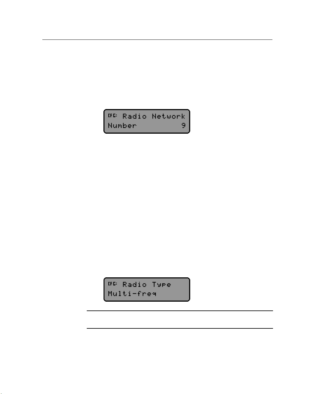
To change which GPS base station an AgGPS 900 radio listens to,
change the network number in the Radio Network screen.
Note – If there is more than one GPS base station on the site, set all
AgGPS 900 radios to the network number that the base station is using.
Each GPS base station must be on a separate radio network. Select a
different network number for each radio network.
3. The 900 MHz radio type is set automatically when the GPS
receiver that the radio is connected to gets its first GPS position.
The Radio Type screen indicates which frequency mode (single
or multi) the radio is in. You do not normally need to modify this
information.
CAUTION – It is illegal to select single frequency mode in USA, Canada,
Australia, and New Zealand.
AgGPS 900 Radio User Guide 29

4 Configuring the Radio
• For multi-frequency radios, use the Radio Frequency screen to
select the country where the radio will be used. This ensures that
the radio uses the correct frequency range for the country. For
example:
• For single-frequency radios, use the Radio Frequency screen to
specify which channel is to be used. For example:
C
40.1 Review radio status
CAUTION – Select the channel that matches the frequency specified on
your license. Consult your Trimble representative for assistance with
mapping the channel number to the actual frequency.
1. Make sure that the radio is attached to the receiver, and that the
receiver is connected to the computer. Start the AgRemote utility
(see page 27).
2. In AgRemote, select Status / RTK. The following screens appear:
–The Radio Product screen shows what type of radio is
connected to the receiver. If no radio is connected, the
message
The Radio Version screen shows the version of firmware in the radio. If
there is no radio connected, the message
No Radio Found appears.
No Radio Found appears.
30 AgGPS 900 Radio User Guide

Configuring the Radio 4
40.1 LED status indicator
The LED can be orange and/or green depending on the situation. The
LED reports the operational status of the AgGPS 900 radio. See
Ta bl e 4 .1 .
Table 4.1 LED Conditions
LED color LED flash Radio Status
Orange Solid Power is supplied
Green Solid Radio is synchronized with source of corrections
Orange+Green 1 Hz flash Radio is in Firmware-Loading mode
Orange+Green Off No power is supplied
AgGPS 900 Radio User Guide 31

4 Configuring the Radio
32 AgGPS 900 Radio User Guide

CHAPTER
5
Mounting the AgGPS Radio 5
In this chapter:
Q Mounting the AgGPS 900 radio on a vehicle
Q Setting up the equipment in the field
Once the AgGPS 900 radio is correctly configured, it is ready to be
mounted on a vehicle. This chapter explains how to mount the unit,
and how to set it up out in the field.
5.1 Mounting the AgGPS 900 radio on a vehicle
When mounting the radio on a vehicle:
• To reduce damage, minimize shock and vibration to the
AgGPS 900 radio.
• Prevent signal interference. Position the antenna away from
rotating beacons, strobe lights, and other antennas (especially if
the other antenna is a two-way radio).
AgGPS 900 Radio User Guide 33

5 Mounting the AgGPS Radio
• Position the radio and receiver on a flat surface at the highest
point along the centerline on the vehicle. However, do not
position them in such a way that they will be damaged if the
vehicle is driven into a shed or storage area.
Note – Mounting must be done in accordance with the processes outlined
in the AgGPS 252 Receiver User Guide, and the AgGPS Autopilot
installation guide appropriate to your vehicle (if an Autopilot system is
being used).
Figure 5.1 shows the mounting kit and how the parts fit together in a
typical radio installation.
Figure 5.1 Radio mounting kit
34 AgGPS 900 Radio User Guide
A
B

Mounting the AgGPS Radio 5
To mount the radio on a vehicle:
1. Attach the radio to the AgGPS 252 GPS receiver.
2. Connect the cable from the radio to Port B on the receiver.
3. Ensure that the radio mounting screws are all fitted with
washers and lock washers.
4. Bolt the combined unit into the AgGPS 252 mounting plate.
5. Use the bolts provided to securely mount the adapter plate to
the vehicle.
6. Use the bolts that are included with the adapter plate to bolt the
AgGPS 252 mounting plate to the adapter plate.
B
Tip – Use threadlocking Loctite or equivalent to secure the bolts.
7. Provide DC power to the GPS receiver. The GPS receiver
provides power to the AgGPS 900 radio.
5.1 Setting up the equipment in the field
• Make sure that each radio is configured to the same network
number.
• Set the serial port settings for the base and all rover GPS
receivers that are using that base to 38.4 Kbps, 8 bits, parity none,
and 1 stop bit. For more information about setting up the GPS
receiver, refer to the GPS receiver manual.
Note – High-power signals from a nearby radio station or radar
transmitter can overwhelm the radio circuits. This does not harm the
radio, but can prevent it from functioning correctly. To avoid problems, try
not to use the radio within 400 meters (1300 feet) of powerful radar,
television, or other transmitters. Low power transmitters, such as those in
portable phones and walkie-talkies, do not usually interfere with AgGPS
radio operation unless they are tuned to the same channel.
AgGPS 900 Radio User Guide 35

5 Mounting the AgGPS Radio
36 AgGPS 900 Radio User Guide

CHAPTER
6
Upgrading the Firmware 6
In this chapter:
Q Firmware upgrade procedure
This chapter describes how to use the FlashLoader 200 utility with the
AgGPS 900 radio in order to perform the following tasks:
• upgrade the radio to use the latest firmware
• review the radio configuration
• collect troubleshooting information
Note – When you upgrade the firmware on the radio, any custom settings
are reset to the factory defaults. Before you upgrade, make a note of any
settings that you have changed. You can reconfigure them after the
upgrade.
AgGPS 900 Radio User Guide 37

6 Upgrading the Firmware
6.1 Firmware upgrade procedure
1. Download the FlashLoader 200 firmware upgrade utility.
2. If you need to upgrade the radio firmware, download the radio
firmware.
3. Install the FlashLoader 200 utility on the office computer.
4. Connect the radio to the office computer.
5. Upgrade the radio firmware.
For more information about each step, see the following sections.
60.1 Step 1: Download the FlashLoader 200 firmware
upgrade utility
1. Go to the Trimble website: www.trimble.com.
2. Click
Support.
3. Click your AgGPS product.
4. Click
Downloads.
5. Click the latest version of the FlashLoader 200 firmware upgrade
utility. The File Download wizard appears.
6. Select Save this program to disk, and then click
7. On the C:\ drive, select My Documents as the destination and
then click
Save. Your internet connection speed determines how
long the download takes (usually 5–30 minutes).
60.1 Step 2: Download the radio firmware
1. Complete Step 1 through Step 4 from the previous section.
2. Click the latest version of the radio firmware. The firmware file
has a *.abs extension.
3. Complete Step 6 through Step 7 from the previous section.
38 AgGPS 900 Radio User Guide
OK.

Upgrading the Firmware 6
60.1 Step 3: Install FlashLoader 200 on the office computer
Install the FlashLoader 200 utility on an office computer that is running
®
a Microsoft
Windows® 95, 98, ME, Windows NT®, Windows 2000, or
XP operating system.
1. Save any open documents and close other applications that are
running on the office computer.
2. Browse to My Documents. If you selected a different location
when you downloaded the firmware, browse to that location
instead.
3. Double-click the FlashLoader 200 file that you downloaded. The
Wel come dialog appears.
4. Click
Next. The Select Destination Directory dialog appears:
5. Click
Next. The Select Additional Tasks dialog appears.
AgGPS 900 Radio User Guide 39

6 Upgrading the Firmware
6. Click Next. The Ready to Install dialog appears:
7. Click
8. Click
60.1 Step 4: Connect the radio to the office computer
Install. The computer installs the FlashLoader 200 utility.
Finish.
For information on how to connect the radio to the office computer, see
Chapter 3.
60.2 Step 5: Upgrade the radio firmware
When you upgrade the firmware on the radio, any custom settings are
reset to the factory defaults. Before you upgrade, make a note of any
settings that you have changed. You can reconfigure them after the
upgrade.
40 AgGPS 900 Radio User Guide

Upgrading the Firmware 6
C
CAUTION – Do not disturb or disconnect the power to the radio while
you are installing the firmware. If power is lost or the computer fails
during the installation, you may have to return the radio to the factory
for service.
1. In Windows, select / Programs / FlashLoader 200. The
FlashLoader 200 dialog appears:
AgGPS 900 Radio User Guide 41

6 Upgrading the Firmware
2. Select the Upload firmware to receiver check box and click
Proceed. The Select Firmware File dialog appears:
3. Select the location of the firmware file and click
FlashLoader 200 dialog displays the location and name of the
firmware file:
42 AgGPS 900 Radio User Guide
Open. The

Upgrading the Firmware 6
4. Click Proceed. The FlashLoader 200 utility establishes
communication with the radio and then transfers the new
firmware.
A progress bar appears during the upgrade. The upgrade process
takes approximately five minutes. When the upgrade is
complete, the message
successfully
appears.
Requested operations completed
5. Click
OK.
6. Exit FlashLoader 200.
You can now use the AgRemote software to reconfigure any
custom settings that you previously had in the radio (See
page 40).
AgGPS 900 Radio User Guide 43

6 Upgrading the Firmware
44 AgGPS 900 Radio User Guide

APPENDIX
A
Technical Specifications A
In this chapter:
Q Technical information
Q Pinout information
This chapter lists the technical specifications of the AgGPS 900 radio,
and shows the pinout information of the RS-232 cable.
AgGPS 900 Radio User Guide 45

A Technical Specifications
A.1 Technical information
Table A.1 shows the technical information for the AgGPS 900 radio.
This information is subject to change without notice.
Table A.1 Technical information
Item Specification
Physical:
Size
Weight
Environmental:
Operating temperature
Storage temperature
Humidity
Vibration
Shock:
Operational
Survival
Electrical
Power consumption:
Nominal
Receive
Protection
Input range
GPS connector:
Typ e
Provides
RF connector:
Typ e
Provides
Indicators Radio Receive Status (Green LED)
300 mm W x 309 mm D x 25.4 mm H
approx. 2.3 kg (5 lbs)
–40 °C through +70 °C
–40 °C through +85 °C
Complies with Mil 810E Method 507.3 Procedure III Aggravated
Cyclic Humidity. Ten 24 hour cycles of constant 95% RH, with cycling
temp and dwells +30 °C and +60 °C.
3.06 gRMS, 5–1000 Hz random vibration
± 40 g for 10 ms in each axis (using a sawtooth waveform)
± 75 g for 6 ms in each axis (using a sawtooth waveform)
300–500 mA at 12 V DC
<2 Watts
LoadDump
Input 9 V DC through 32 V DC
12-pin Deutsch connector
Power and 1 serial port
Female TNC 50 ohm connector
Radio input
Power Status (Orange LED)
46 AgGPS 900 Radio User Guide

Table A.1 Technical information (continued)
Item Specification
AgGPS 900 radio performance
Range:
Optimal
Typ ical
Radio link:
Frequency range
Networks
Wireless data rates
Modes
A.2 Pinout information
10 km (6 miles)
3 km–5 km (2 miles–3 miles)
Varies with terrain and operating conditions
902 MHz–928 MHz (in USA and Canada)
40 user selectable networks
128 Kbps
Rover
Figure A.1 shows the pinout information for the AgGPS 900 radio.
123456
Technical Specifications A
12 11 10 9 8 7
Pin Function
1Not connected
2 TX (transmit data from radio)
3RX (receive data by radio)
4Not connected
5GND
6Not connected
Figure A.1 AgGPS 900 radio RS-232 pinout connections
Pin Function
7Not connected
8Not connected
9Not connected
10 V+
11 V–
12 Not connected
AgGPS 900 Radio User Guide 47

A Technical Specifications
48 AgGPS 900 Radio User Guide

Index
A
about the radio 12, 18
AgRemote 25
configuring the radio with 29
reviewing status of radio 30
starting 27
using 26
Autopilot 25, 28
B
base station 16
baud rate, default 26
C
cautions
changing or modifying equipment 8
installing firmware 41
selecting channel for license 30
single frequency mode 29
channel, selecting 30
CMR format 18
CMR+ format 18
comments 13
computer
connecting to radio 23
configuring 25
communication 28
radio with AgRemote 29
connecting
radio to office computer 23
radio to receiver 22
D
data bits, default 26
data format 18
default settings 26
description, technical 16
F
features 17
feedback 13
firmware version, viewing 30
FlashLoader 200 utility
downloading firmware 38
downloading utility 38
installing 39
upgrading firmware 37, 40
frequency band 17
frequency mode, single or multi 29
I
interference 35
introduction 11
AgGPS 900 Radio User Guide 49

Index
L
LED, status indicator 31
licensing 8
low voltage 17
M
maintenance 3
messages
No Radio Found 29, 30
Unknown 29
N
network setting 29
No Radio Found message 29, 30
notes
release 12
update 12
O
options 18
P
parity, default 26
pinout information 47
port settings 26
power consumption 46
power loss 17
R
radio
configuring using AgRemote 29
connecting to office computer 23
mounting on vehicle 33
status 30
radio frequency (RF) energy 8
receiver
configuring Port B of 28
connecting to 22
release notes 12
repeater 16
RF energy 8
RS-232 pinout information 47
RTCM 18
S
setting up
in the field 35
single frequency mode 30
SiteNet radio 16, 18
status indicator LED 31
status, radio 30
stop bits, default 26
support 12
T
technical information 46
technical support 12
temperature 46
TRIMCOMM 900 radio 18
turbo mode 19
type approval 8
U
Unknown message 29
update notes 12
upgrading firmware 38
use and care 3
W
website 11
50 AgGPS 900 Radio User Guide


 Loading...