

Page 1

F
Version 1.00
Revision A
Part Number 55510-00-ENG
February 2004
AgGPS® 252 Receiver
User Guide
Ag252_100A_UserGde_ENG.book Page i Wednesday, January 28, 2004 5:42 PM
Page 2

ii AgGPS 252 Receiver User Guide
Contact Information
Trimble Navigation Limited
Agriculture Business Area
9290 Bond Street, Suite 102
Overland Park, KS 66214
USA
+1-913-495-2700 Phone
trimble_support@trimble.com
www.trimble.com
Copyright and Trademarks
© 2004, Trimble Navigation Limited. All rights
reserved.
Trimble, the Globe & Triangle logo, and AgGPS are
trademarks of Trimble Navigation Limited, registered in
the United States Patent and Trademark Office and other
countries. EVEREST, MS750, and SiteNet are
trademarks of Trimble Navigation Limited.
Microsoft and ActiveSync are either registered
trademarks or trademarks of Microsoft Corporation in
the United States and/or other countries. All other
trademarks are the property of their respective owners.
Release Notice
This is the February 2004 release (Revision A) of the
AgGPS 252 Receiver User Guide, part number
55510-00-ENG. It applies to version 1.00 of the AgGPS
252 receiver.
The following limited warranties give you specific legal
rights. You may have others, which vary from
state/jurisdiction to state/jurisdiction.
Hardware Limited Warranty
Trimble Navigation Limited warrants that this hardware
product (the “Product”) will perform substantially in
accordance with published specifications and be
substantially free of defects in material and
workmanship for a period of one (1) year starting from
the date of delivery. The warranty set forth in this
paragraph shall not apply to software products.
Software License, Limited Warranty
This Trimble software product, whether provided as a
stand-alone computer software product, built into
hardware circuitry as firmware, embedded in flash
memory, or stored on magnetic or other media, (the
“Software”) is licensed and not sold, and its use is
governed by the terms of the relevant End User License
Agreement (“EULA”) included with the Software. In the
absence of a separate EULA included with the Software
providing different limited warranty terms, exclusions
and limitations, the following terms and conditions shall
apply. Trimble warrants that this Trimble Software
product will substantially conform to Trimble’s
applicable published specifications for the Software for
a period of ninety (90) days, starting from the date of
delivery.
Warranty Remedies
Trimble's sole liability and your exclusive remedy under
the warranties set forth above shall be, at Trimble’s
option, to repair or replace any Product or Software that
fails to conform to such warranty (“Nonconforming
Product”) or refund the purchase price paid by you for
any such Nonconforming Product, upon your return of
any Nonconforming Product to Trimble in accordance
with Trimble’s standard return material authorization
procedures.
Warranty Exclusions and Disclaimer
These warranties shall be applied only in the event and
to the extent that (i) the Products and Software are
properly and correctly installed, configured, interfaced,
maintained, stored, and operated in accordance with
Trimble's relevant operator's manual and specifications,
and; (ii) the Products and Software are not modified or
misused. The preceding warranties shall not apply to,
and Trimble shall not be responsible for defects or
performance problems resulting from (i) the
combination or utilization of the Product or Software
with hardware or software products, information, data,
systems, interfaces or devices not made, supplied or
specified by Trimble; (ii) the operation of the Product or
Software under any specification other than, or in
addition to, Trimble's standard specifications for its
products; (iii) the unauthorized, installation,
modification, or use of the Product or Software; (iv)
damage caused by accident, lightning or other electrical
discharge, fresh or salt water immersion or spray; or (v)
normal wear and tear on consumable parts (e.g.,
batteries). Trimble does not warrant or guarantee the
results obtained through the use of the Product.
THE WARRANTIES ABOVE STATE TRIMBLE'S ENTIRE
LIABILITY, AND YOUR EXCLUSIVE REMEDIES,
RELATING TO PERFORMANCE OF THE PRODUCTS
AND SOFTWARE. EXCEPT AS OTHERWISE
EXPRESSLY PROVIDED HEREIN, THE PRODUCTS,
SOFTWARE, AND ACCOMPANYING
DOCUMENTATION AND MATERIALS ARE PROVIDED
“
AS-IS” AND WITHOUT EXPRESS OR IMPLIED
WARRANTY OF ANY KIND BY EITHER TRIMBLE
NAVIGATION LIMITED OR ANYONE WHO HAS BEEN
INVOLVED IN ITS CREATION, PRODUCTION,
INSTALLATION, OR DISTRIBUTION INCLUDING, BUT
NOT LIMITED TO, THE IMPLIED WARRANTIES OF
MERCHANTABILITY AND FITNESS FOR A
PARTICULAR PURPOSE, TITLE, AND
NONINFRINGEMENT. THE STATED EXPRESS
WARRANTIES ARE IN LIEU OF ALL OBLIGATIONS OR
LIABILITIES ON THE PART OF TRIMBLE ARISING
OUT OF, OR IN CONNECTION WITH, ANY PRODUCTS
OR SOFTWARE. SOME STATES AND JURISDICTIONS
DO NOT ALLOW LIMITATIONS ON DURATION OR
THE EXCLUSION OF AN IMPLIED WARRANTY, SO
Ag252_100A_UserGde_ENG.book Page ii Wednesday, January 28, 2004 5:42 PM
Page 3
AgGPS 252 Receiver User Guide iii
THE ABOVE LIMITATION MAY NOT APPLY TO YOU.
TRIMBLE NAVIGATION LIMITED IS NOT
RESPONSIBLE FOR THE OPERATION OR FAILURE OF
OPERATION OF GPS SATELLITES OR THE
AVAILABILITY OF GPS SATELLITE SIGNALS.
Limitation of Liability
TRIMBLE’S ENTIRE LIABILITY UNDER ANY
PROVISION HEREIN SHALL BE LIMITED TO THE
AMOUNT PAID BY YOU FOR THE PRODUCT OR
SOFTWARE LICENSE. TO THE MAXIMUM EXTENT
PERMITTED BY APPLICABLE LAW, IN NO EVENT
SHALL TRIMBLE OR ITS SUPPLIERS BE LIABLE FOR
ANY INDIRECT, SPECIAL, INCIDENTAL OR
CONSEQUENTIAL DAMAGES WHATSOEVER UNDER
ANY CIRCUMSTANCE OR LEGAL THEORY RELATING
IN ANY WAY TO THE PRODUCTS, SOFTWARE AND
ACCOMPANYING DOCUMENTATION AND
MATERIALS, (INCLUDING, WITHOUT LIMITATION,
DAMAGES FOR LOSS OF BUSINESS PROFITS,
BUSINESS INTERRUPTION, LOSS OF BUSINESS
INFORMATION, OR ANY OTHER PECUNIARY LOSS),
REGARDLESS WHETHER TRIMBLE HAS BEEN
ADVISED OF THE POSSIBILITY OF ANY SUCH LOSS
AND REGARDLESS OF THE COURSE OF DEALING
WHICH DEVELOPS OR HAS DEVELOPED BETWEEN
YOU AND TRIMBLE. BECAUSE SOME STATES AND
JURISDICTIONS DO NOT ALLOW THE EXCLUSION OR
LIMITATION OF LIABILITY FOR CONSEQUENTIAL OR
INCIDENTAL DAMAGES, THE ABOVE LIMITATION
MAY NOT APPLY TO YOU.
NOTE: THE ABOVE LIMITED WARRANTY
PROVISIONS MAY NOT APPLY TO PRODUCTS OR
SOFTWARE PURCHASED IN THE EUROPEAN UNION.
PLEASE CONTACT YOUR TRIMBLE DEALER FOR
APPLICABLE WARRANTY INFORMATION.
Notices
USA
NOTE – FCC Part 15 rules; paragraph 15.105
This equipment has been tested and found to comply
with the limits for a Class A digital device, pursuant to
Part 15 of the FCC Rules. These limits are designed to
provide reasonable protection against harmful
interference when the equipment is operated in a
commercial environment. This equipment generates,
uses, and can radiate radio frequency energy and, if not
installed and used in accordance with the instruction
manual, may cause harmful interference to radio
communications. Operation of this equipment in a
residential area is likely to cause harmful interference, in
which case, you, the user, will be required to correct the
interference at your own expense.
If this equipment does cause harmful interference to
radio or television reception, which can be determined
by turning the equipment off and on, the user is
encouraged to try to correct the interference by one or
more of the following measures:
– Reorient or relocate the receiving antenna.
– Increase the separation between the equipment and
the receiver.
– Connect the equipment into an outlet on a circuit
different from that to which the receiver is connected.
– Consult the dealer or an experienced radio/TV
technician for help.
Changes and modifications not expressly approved by
the manufacturer or registrant of this equipment can
void your authority to operate this equipment under
Federal Communications Commission rules.
Europe
This product has been tested and found to comply with
the requirements for the European Directive
75/322/EEC as amended by 2000/2/EC thereby
satisfying the requirements for e-mark compliance for
use in agricultural vehicles in the European Economic
Area (EEA).
This product has been tested and found to comply with
the requirements for a Class A device pursuant to
European Council Directive 89/336/EEC on EMC,
thereby satisfying the requirements for CE Marking and
sale within the European Economic Area (EEA).
C
Warning – This is a Class A product. In a domestic
environment this product may cause radio
interference in which case you may be required to
take adequate measures.
Ag252_100A_UserGde_ENG.book Page iii Wednesday, January 28, 2004 5:42 PM
Page 4

iv AgGPS 252 Receiver User Guide
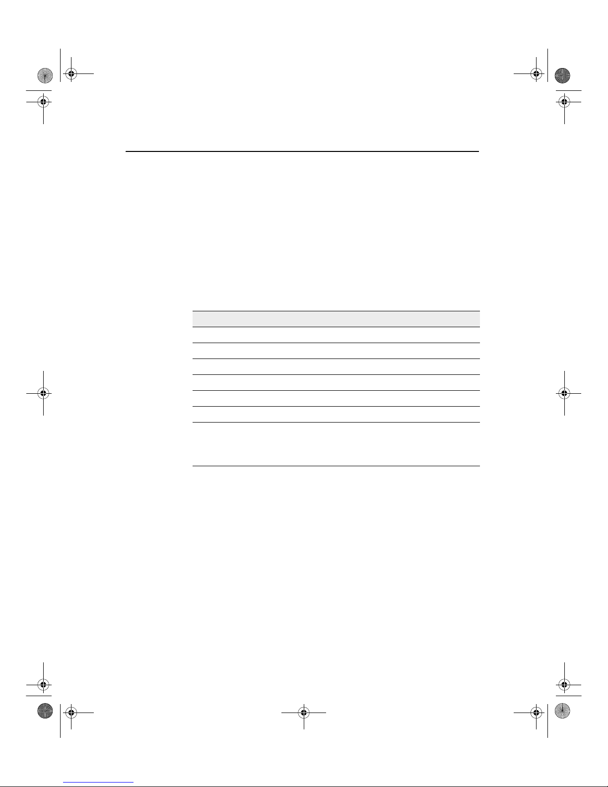
Declaration of Conformity
This product conforms to the following standards, and therefore complies with the requirements of the R&TTE
Directive 1999/5/EC, which specifies compliance with the essential requirements of EMC Directive 89/336/EEC and
Low Voltage Directive 73/23/EEC.
The technical file is maintained at Trimble Navigation Limited, 749 North Mary Avenue, PO Box 3642, Sunnyvale,
CA 94088-3642, USA.
EMC Emissions BSEN 55022:1998 (W/A1:00) Class A
EMC Immunity EN 55024:1998
Safety EN 60950:2000
Mark First Applied 03
Ag252_100A_UserGde_ENG.book Page iv Wednesday, January 28, 2004 5:42 PM
Page 5

AgGPS 252 Receiver User Guide v
Contents
1 Introduction . . . . . . . . . . . . . . . . . . . . . . . . . . 1
Warnings . . . . . . . . . . . . . . . . . . . . . . . . . . . . . . . . . . . 2
Related Information . . . . . . . . . . . . . . . . . . . . . . . . . . . . . . 2
Technical Assistance . . . . . . . . . . . . . . . . . . . . . . . . . . . . . 2
Your Comments . . . . . . . . . . . . . . . . . . . . . . . . . . . . . . . . 2
2 Overview . . . . . . . . . . . . . . . . . . . . . . . . . . . . 3
Introduction . . . . . . . . . . . . . . . . . . . . . . . . . . . . . . . . . . 4
Standard Features of the AgGPS 252 Receiver . . . . . . . . . . . . . . . . 4
Receiver Connections . . . . . . . . . . . . . . . . . . . . . . . . . . . . . 5
Receiver Input/Output . . . . . . . . . . . . . . . . . . . . . . . . . . . . 6
LED Indicator . . . . . . . . . . . . . . . . . . . . . . . . . . . . . . . . . 8
GPS Positioning Methods. . . . . . . . . . . . . . . . . . . . . . . . . . 10
RTK GPS positioning . . . . . . . . . . . . . . . . . . . . . . . . 10
Differential GPS positioning (DGPS) . . . . . . . . . . . . . . . . 11
Autonomous GPS positioning . . . . . . . . . . . . . . . . . . . . 12
Sources of Error in GPS Positioning . . . . . . . . . . . . . . . . . . . . 13
Coordinate systems. . . . . . . . . . . . . . . . . . . . . . . . . . 15
3 Installing the Receiver. . . . . . . . . . . . . . . . . . . . 17
Introduction . . . . . . . . . . . . . . . . . . . . . . . . . . . . . . . . . 18
System Components . . . . . . . . . . . . . . . . . . . . . . . . . . . . 18
Optional extra . . . . . . . . . . . . . . . . . . . . . . . . . . . . 18
Mounting the Receiver . . . . . . . . . . . . . . . . . . . . . . . . . . . 19
Choosing a location . . . . . . . . . . . . . . . . . . . . . . . . . 19
Environmental conditions . . . . . . . . . . . . . . . . . . . . . . 20
Ag252_100A_UserGde_ENG.book Page v Wednesday, January 28, 2004 5:42 PM
Page 6

Contents
vi AgGPS 252 Receiver User Guide
Electrical interference . . . . . . . . . . . . . . . . . . . . . . . . 20
Connecting to an External Device . . . . . . . . . . . . . . . . . . . . . 21
Connectors and Pinouts . . . . . . . . . . . . . . . . . . . . . . . . . . . 24
Port A . . . . . . . . . . . . . . . . . . . . . . . . . . . . . . . 25
Port B . . . . . . . . . . . . . . . . . . . . . . . . . . . . . . . 26
4 Configuring the Receiver . . . . . . . . . . . . . . . . . . 27
Introduction . . . . . . . . . . . . . . . . . . . . . . . . . . . . . . . . . 28
AgRemote Home Screen . . . . . . . . . . . . . . . . . . . . . . . . . . 29
Configuring Differential GPS. . . . . . . . . . . . . . . . . . . . . . . . 30
OmniSTAR . . . . . . . . . . . . . . . . . . . . . . . . . . . . . . 31
WAAS/EGNOS . . . . . . . . . . . . . . . . . . . . . . . . . . . 32
Configuring the AgGPS 252 Receiver to Operate in RTK Mode . . . . . . 33
Configuring the Communication Ports . . . . . . . . . . . . . . . . . . . 33
Configuring input/output communication . . . . . . . . . . . . . . 34
5 Troubleshooting . . . . . . . . . . . . . . . . . . . . . . . 39
Introduction . . . . . . . . . . . . . . . . . . . . . . . . . . . . . . . . . 40
Problems and Solutions . . . . . . . . . . . . . . . . . . . . . . . . . . . 40
Troubleshooting Flowcharts . . . . . . . . . . . . . . . . . . . . . . . . 48
A Specifications . . . . . . . . . . . . . . . . . . . . . . . . 55
AgGPS 252 Receiver . . . . . . . . . . . . . . . . . . . . . . . . . . . . 55
GPS Channels . . . . . . . . . . . . . . . . . . . . . . . . . . . . . . . . 56
L-Band Satellite Differential Correction Receiver . . . . . . . . . . . . . 58
Receiver Default Settings . . . . . . . . . . . . . . . . . . . . . . . . . . 58
B Third-Party Interface Requirements . . . . . . . . . . . . 59
Third-Party Software . . . . . . . . . . . . . . . . . . . . . . . . . . . . 59
Third-Party Hardware. . . . . . . . . . . . . . . . . . . . . . . . . . . . 61
Index . . . . . . . . . . . . . . . . . . . . . . . . . . . . . 65
Ag252_100A_UserGde_ENG.book Page vi Wednesday, January 28, 2004 5:42 PM
Page 7
CHAPTER
1
AgGPS 252 Receiver User Guide 1
Introduction 1
Welcome to the AgGPS 252 Receiver User Guide. This manual:
• Describes how to install and configure the Trimble
®
AgGPS
®
252 receiver.
• Provides guidelines for connecting the receiver to an external
device.
• Provides guidelines for using the AgRemote utility to view and
configure the receiver correction sources and other operating
parameters.
Even if you have used other Global Positioning System (GPS)
products before, Trimble recommends that you spend some time
reading this manual to learn about the special features of this product.
If you are not familiar with GPS, go to the Trimble website at
www.trimble.com for an interactive look at Trimble and GPS.
Ag252_100A_UserGde_ENG.book Page 1 Wednesday, January 28, 2004 5:42 PM
Page 8

1 Introduction
2 AgGPS 252 Receiver User Guide
1.1 Warnings
Always follow the instructions that accompany a warning.
C
Warning – Indicates a potential hazard or unsafe practice that could result
in injury or property damage.
1.2 Related Information
Release notes describe new features, provide information that is not
included in the manuals, and identify changes to the manuals. You can
download release notes from the Trimble website.
1.3 Technical Assistance
If you have a problem and cannot find the information you need in the
product documentation, contact your local Trimble Reseller.
1.4 Your Comments
Your feedback about the supporting documentation helps us to
improve it with each revision. Email your comments to
ReaderFeedback@trimble.com.
Ag252_100A_UserGde_ENG.book Page 2 Wednesday, January 28, 2004 5:42 PM
Page 9

CHAPTER
2
AgGPS 252 Receiver User Guide 3
Overview 2
In this chapter:
Introduction
Standard Features of the AgGPS 252 Receiver
Receiver Connections
Receiver Input/Output
LED Indicator
GPS Positioning Methods
Sources of Error in GPS Positioning
Ag252_100A_UserGde_ENG.book Page 3 Wednesday, January 28, 2004 5:42 PM
Page 10

2 Overview
4 AgGPS 252 Receiver User Guide
2.1 Introduction
This chapter describes the AgGPS 252 receiver and gives an overview
of GPS, DGPS, and related information. When used with a Real-Time
Kinematic (RTK) base station, the AgGPS 252 receiver provides RTK
positioning for high-accuracy, centimeter-level applications. For
physical specifications, see Appendix A, Specifications.
2.2 Standard Features of the AgGPS 252 Receiver
A standard AgGPS 252 receiver provides the following features:
• 12 GPS (C/A-code) tracking channels, code carrier channels
• Horizontal RTK positioning accuracy 2.5 cm (0.98 in) + 2 ppm,
2 sigma; vertical RTK positioning accuracy 3.7 cm (1.46 in)
+ 2ppm, 2sigma
• Submeter differential accuracy (RMS), assuming at least five
satellites and a PDOP of less than four
• Combined GPS/DGPS receiver and antenna
• System level cable
• AgRemote utility with four-button keypad to configure and view
system properties (download from the Trimble website at
www.trimble.com)
• LED status indicator
• The receiver outputs a 1 PPS (pulse per second) strobe signal on
both ports. This signal enables an external instrument to
synchronize its internal time with a time derived from the very
accurate GPS system time.
• WAAS differential correction compatibility
• AgGPS 170 Field Computer compatibility
• EVEREST™ multipath rejection technology
• OmniSTAR VBS and HP positioning compatibility
Ag252_100A_UserGde_ENG.book Page 4 Wednesday, January 28, 2004 5:42 PM
Page 11
AgGPS 252 Receiver User Guide 5
Overview 2
• Two ports that support both CAN 2.0B and RS-232:
CAN
– J1939 and NMEA 2000 messages
Note – The AgGPS 252 is ISO 11783 compliant. It supports
some ISO 11783 messages.
RS-232
– NMEA-0183 output: GGA, GLL, GRS, GST, GSA, GSV,
MSS, RMC, VTG, ZDA, XTE (the default NMEA
messages are GGA, GSA, VTG, and RMC)
Note – PTNLDG, PTNLEV, PTNLGGK, PTNLID, and
PTNLSM are Trimble proprietary NMEA output messages.
– RTCM SC-104 output
– Trimble Standard Interface Protocol (TSIP) input and
output
2.3 Receiver Connections
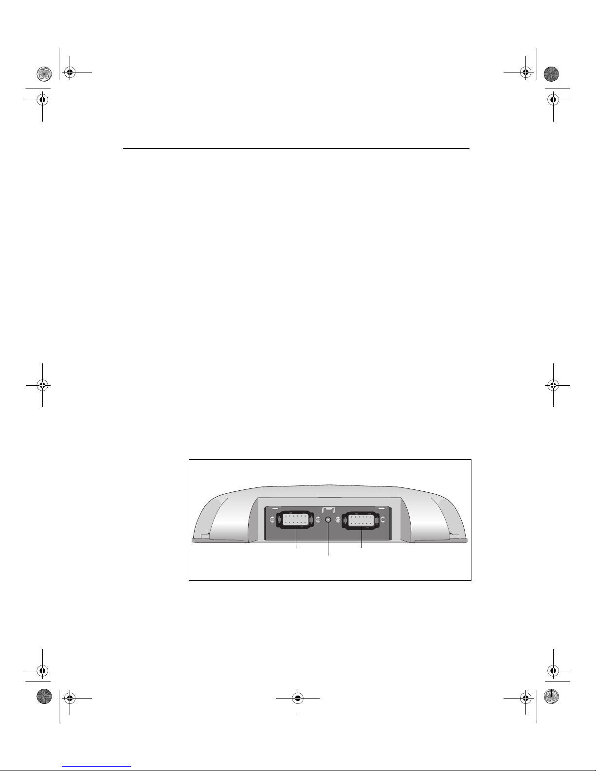
Figure 2.1 shows the connector ports and the LED indicator on the
AgGPS 252 receiver.
Figure 2.1 AgGPS 252 receiver connector ports
LED indicator
Port A Port B
Ag252_100A_UserGde_ENG.book Page 5 Wednesday, January 28, 2004 5:42 PM
Page 12

2 Overview
6 AgGPS 252 Receiver User Guide
The two connectors (Port A and Port B) can perform the following
functions:
• accept power
• accept TSIP, RTCM, ASCII, and (if enabled) CMR inputs
• output RTCM, TSIP, and NMEA messages
• output 1 PPS signals
• provide support for the J1939 (CAN) serial bus
For more information about the inputs, outputs, and LED indicators,
see the information in the rest of this section.
2.4 Receiver Input/Output
The AgGPS 252 receiver data/power cable (P/N 50166) connects to a
receiver connector port to supply power. It also enables the following
data exchanges:
• TSIP, RTCM, and ASCII input from an external device
The receiver is able to receive ASCII data from an external
device, convert this data into an NMEA message, and export the
message to another device. TSIP command packets configure
and monitor GPS and DGPS parameters. The receiver is also
able to accept RTCM data from an external device, such as a
radio.
• CMR input from an external device
If the receiver is to be used in RTK mode, set the port that is
connected to the radio to the RtkLnk protocol. This protocol
enables the receiver to receive CMR messages.
• TSIP and NMEA output to an external device
When you are using an external radio, the receiver can also
receive DGPS corrections.
TSIP is input/output when communicating with AgRemote.
Ag252_100A_UserGde_ENG.book Page 6 Wednesday, January 28, 2004 5:42 PM
Page 13

AgGPS 252 Receiver User Guide 7
Overview 2
NMEA is output when the receiver is exporting GPS position
information to an external device, such as a yield monitor, or to
a mapping software program.
For more information on the National Marine Electronics
Association (NMEA) and Radio Technical Commission for
Maritime Services (RTCM) communication standard for GPS
receivers, go to the following websites:
– www.nmea.org
– www.rtcm.org
On the Trimble website ((www.trimble.com), refer to the
document called NMEA-0183 Messages Guide for AgGPS
Receivers.
• 1 PPS output
To synchronize timing between external instruments and the
internal clock in the receiver, the connection port outputs a
strobe signal at 1 PPS (pulse per second). To output this signal,
the receiver must be tracking satellites and computing GPS
positions.
• J1939 (CAN) bus
Both connection ports on the receiver support the J1939
Controller Area Network (CAN) bus protocol. This protocol
standardizes the way multiple microprocessor-based electronic
control units (ECUs) communicate with each other over the
same pair of wires. It is used in off-highway machines, such as
those used in agriculture, construction, and forestry.
For more information, go to the Society of Automotive
Engineers (SAE) International website at
www.sae.org/servlets/index.
• ISO 11783 messages
Both CAN ports support some ISO 11783 messages.
Ag252_100A_UserGde_ENG.book Page 7 Wednesday, January 28, 2004 5:42 PM
Page 14

2 Overview
8 AgGPS 252 Receiver User Guide
Position output format
The AgGPS receiver outputs positions in Degrees, Minutes, and
Decimal Minutes (DDD°MM.m'). This is the NMEA standard format
and is commonly used worldwide for data transfer between electronic
equipment.
2.5 LED Indicator
The AgGPS 252 receiver has an LED light that shows the status of the
receiver. The following tables describe the light sequences for each
positioning method.
Note – WAAS/EGNOS and OmniSTAR VBS use the Satellite
Differential GPS positioning method.
Table 2.1 LED sequences with Satellite Differential GPS or Autonomous positioning
LED color LED flash Status
Off Off No power
Green Solid Normal operation: computing DGPS positions
Green Slow No DGPS corrections: computing DGPS positions using old
corrections
Green Fast No DGPS corrections approaching DGPS age limit: computing
DGPS positions using old corrections
Yellow Solid DGPS corrections being received but DGPS positions not yet being
computed: computing autonomous GPS positions
Yellow Slow No DGPS corrections: computing autonomous GPS positions
Yellow F ast Not enough GPS signals: not tracking enough satellites to compute
position
Ag252_100A_UserGde_ENG.book Page 8 Wednesday, January 28, 2004 5:42 PM
Page 15

AgGPS 252 Receiver User Guide 9
Overview 2
Table 2.2 LED sequences with RTK positioning
LED color LED flash Status
Off Off No power
Green Solid Normal operation: computing fixed RTK positions
Green Slow Receiving CMR corrections but not initialized: computing float RTK
positions
Green Fast No CMR corrections: computing RTK position using old corrections
Yellow Solid Receiving CMR corrections but unable to calculate RTK position:
computing DGPS (if WAAS/EGNOS is unavailable) or autonomous
position
Yellow Slow No CMR corrections: computing DGPS or autonomous position
Yellow Fast Not receiving CMR corrections: not computing positions
Table 2.3 LED sequences with OmniSTAR HP positioning
LED color LED flash Status
Off Off No power
Green Solid Normal operation: computing converged OmniSTAR HP positions
Green Slow Receiving OmniSTAR HP corrections, but only able to compute
unconverged position
Green Fast Receiving OmniSTAR HP corrections, but an HP error occurred
Yellow Solid Receiving OmniSTAR HP corrections but unable to calculate a
position: computing DGPS or autonomous solution
Yellow Slow No OmniSTAR HP corrections: computing DGPS or autonomous
position
Yellow Fast Not tracking OmniSTAR HP corrections: no positions
Ag252_100A_UserGde_ENG.book Page 9 Wednesday, January 28, 2004 5:42 PM
Page 16
2 Overview
10 AgGPS 252 Receiver User Guide
2.6 GPS Positioning Methods
GPS positioning systems are used in different ways to provide
different levels of accuracy. Accuracy is measured in absolute terms
(you know exactly where you are in a fixed reference frame).
Table 2.4 summarizes the GPS positioning methods. Imperial units in
this table are rounded to two decimal places. The values shown are
2sigma.
Table 2.4 Absolute accuracy of GPS positioning methods
For more information about each positioning method, see below.
26.1 RTK GPS positioning
The AgGPS 252 receiver uses the RTK positioning method to achieve
centimeter-level accuracy. To use the RTK method, you must first set
up a base station. The base station uses a radio link to broadcast RTK
corrections to one or more rover receivers. The AgGPS 252 receiver is
a rover receiver, so another compatible receiver, such as a Trimble
MS750™ or AgGPS 214 GPS receiver, must be used as the base
station.
GPS positioning
method
Corrections used Approximate absolute accuracy
Real-Time Kinematic
(RTK) GPS
Trimble CMR
corrections broadcast
by a local base station
2.5 cm (0.98 in) + 2 ppm horizontal
accuracy,
3.7 cm (1.46 in) + 2 ppm vertical accuracy
Satellite Differential GPS OmniSTAR VBS 78 cm (30.71 in)
Satellite Differential GPS WAAS/EGNOS 95 cm (37.40 in)
OmniSTAR HP
Differential GPS
OmniSTAR HP 10 cm (3.94 in) after the signal has fully
converged
1
1
Convergence time can vary, depending on the environment. Time to the first fix (submeter accuracy) is typically
<30 seconds; time to the first high accuracy fix (<10 cm accuracy) is typically <30 minutes.
Ag252_100A_UserGde_ENG.book Page 10 Wednesday, January 28, 2004 5:42 PM
Page 17

AgGPS 252 Receiver User Guide 11
Overview 2
The rover receiver uses RTK corrections from the base station to
calculate its position to centimeter-level accuracy. As part of this
process, the rover receiver must calculate an initialization. This takes a
few seconds. While the receiver is initializing, an RTK Float solution
is generated. Once initialized, an RTK Fixed solution is generated. It is
the RTK Fixed solution that provides centimeter-level accuracy.
The parts per million (ppm) error is dependent on the distance
(baseline length) between the base and rover receiver. For example, if
the distance is 10 km, a 2 ppm error equals 20 mm.
For more information about RTK positioning, go to the Trimble
website at www.trimble.com/gps/
26.2 Differential GPS positioning (DGPS)
For differential positioning, the AgGPS 252 receiver uses corrections
from WAAS/EGNOS satellites or from OmniSTAR VBS or HP
satellites.
These differential systems use special algorithms to provide
differential corrections that allow the rover receiver to calculate its
position more accurately.
Free corrections
WAAS/EGNOS corrections are free in North America and Europe.
For more information about WAAS, go to the Federal Aviation
Administration website at
http://gps.faa.gov/Programs/WAAS/waas.htm.
For more information about EGNOS, go to the European Space
Agency website at
www.esa.int/export/esaSA/GGG63950NDC_navigation_0.html.
Ag252_100A_UserGde_ENG.book Page 11 Wednesday, January 28, 2004 5:42 PM
Page 18

2 Overview
12 AgGPS 252 Receiver User Guide
Subscription-based corrections
The AgGPS 252 receiver uses OmniSTAR HP or OmniSTAR VBS
differential corrections in the same way that it uses WAAS/EGNOS
corrections.
OmniSTAR corrections are provided on a subscription basis.
The corrections that are produced by OmniSTAR HP algorithms are
more accurate than the corrections that are produced by OmniSTAR
VBS algorithms. The accuracy of the positions reported using
OmniSTAR HP increases with the time that has elapsed since the
instrument was turned on. This process is called convergence.
Convergence to where the error is estimated to be below 30 cm
(approximate 12 inches) typically takes around 20 minutes. Factors
that influence the time to convergence include the environment, the
geographical location, and the distance to the closest OmniSTAR
corrections base station. OmniSTAR is continually improving the
service.
For more information about OmniSTAR, go to the OmniSTAR
website at www.omnistar.com. For information about activating an
OmniSTAR subscription, see OmniSTAR, page 31.
26.3 Autonomous GPS positioning
Autonomous GPS positioning uses no corrections. The rover receiver
calculates its position using only the GPS signals it receives. This
method does not have high absolute accuracy, but the relative
accuracy is comparable to the other methods.
Ag252_100A_UserGde_ENG.book Page 12 Wednesday, January 28, 2004 5:42 PM
Page 19
AgGPS 252 Receiver User Guide 13
Overview 2
2.7 Sources of Error in GPS Positioning
The GPS positioning method influences the accuracy of the GPS
position that is output by the AgGPS 252 receiver. The factors
described in Table 2.5 also affect GPS accuracy.
Table 2.5 Factors that influence the accuracy of GPS positions
Condition Optimum
value
Description
Atmospheric
effects
GPS signals are degraded as they travel through the
ionosphere. The error introduced is in the range of 10 meters.
The error is removed by using a differential or RTK positioning
method.
Number of
satellites used
> 5 To calculate a 3D position (latitude and longitude, altitude, and
time), four or more satellites must be visible. To calculate a 2D
position (latitude and longitude, and time), three or more
satellites must be visible. For R TK positioning, five satellites are
needed for initialization. Once initialized, four or more satellites
provide RTK positions. The number of visible satellites
constantly changes and is typically in the range 5 through 9.
The AgGPS receiver can track up to 12 satellites
simultaneously.
Note – To see when the maximum number of GPS satellites are
available, use the Trimble Planning software and a current
ephemeris (satellite history) file. Both files are available free from
the Trimble website at www.trimble.com.
Maximum PDOP < 4 Position Dilution of Precision (PDOP) is a unitless, computed
measurement of the geometry of satellites above the current
location of the receiver. A low PDOP means that the positioning
of satellites in the sky is good, and therefore good positional
accuracy is obtained.
Ag252_100A_UserGde_ENG.book Page 13 Wednesday, January 28, 2004 5:42 PM
Page 20
2 Overview
14 AgGPS 252 Receiver User Guide
Signal-to-noise
ratio
> 6 Signal-to-noise ratio (SNR) is a measure of the signal strength
against electrical background noise. A high SNR gives better
accuracy.
Normal values are:
•GPS 6
• WAAS 3+
• OmniSTAR HP/VBS 6+
Minimum
elevation
> 10 Satellites that are low on the horizon typically produce weak
and noisy signals and are more difficult for the receiver to track.
Satellites below the minimum elevation angle are not tracked.
Multipath
environment
Low Multipath errors are caused when GPS signals are reflected off
nearby objects and reach the receiver by two or more different
paths. The receiver incorporates the EVEREST multipath
rejection option.
RTCMcompatible
corrections
These corrections are broadcast from a Trimble AgGPS 214,
MS750, or equivalent reference station.
RTK Base station
coordinate
accuracy
For RTK positioning, it is important to know the base station
coordinates accurately. Any error in the position of the base
station affects the position of the rover; every 10 m of error in a
base station coordinate can introduce up to 1 ppm scale error
on every measured baseline. For example, an error of 10 m in
the base station position produces an error of 10 mm over a
10 km baseline to the rover.
For more information about how to make sure the position of
your base station is accurate, refer to the manual for your base
station receiver.
Multiple RTK
base stations
If you are using several base stations to provide RTK
corrections to a large site area, all base stations must be
coordinated relative to one another. If they are not, the absolute
positions at the rover will be in error. F or more inf ormation about
how to use several base stations to cover your site , contact your
local Trimble Reseller.
Table 2.5 Factors that influence the accuracy of GPS positions (continued)
Condition Optimum
value
Description
Ag252_100A_UserGde_ENG.book Page 14 Wednesday, January 28, 2004 5:42 PM
Page 21
AgGPS 252 Receiver User Guide 15
Overview 2
27.1 Coordinate systems
Geographic data obtained from different sources must be referenced to
the same datum, ellipsoid, and coordinate format. Different formats
provide different coordinate values for any geographic location. In
North America, the datums NAD-27 and NAD-83 are commonly used
in Agricultural mapping applications.
The AgGPS 252 receiver outputs position coordinates in several
datums and ellipsoids depending on the GPS positioning method
being used. See Table 2.6.
For more information, go to the National Geodetic Survey website at
www.ngs.noaa.gov/faq.shtml#WhatDatum
Table 2.6 DGPS coordinate systems
GPS positioning method Datum Ellipsoid
None – Autonomous mode WGS-84
1
WGS-84
OmniSTAR VBS North American Beams NAD-83
2
GRS-80
OmniSTAR VBS Rest of World Beams ITRF
3
GRS-80
OmniSTAR HP ITRF 2000 ITRF 2000
WAAS Beams WGS-84 WGS-84
RTK WGS-84 WGS-84
1
World Geodetic System (WGS) 1984. Datum and ellipsoid.
2
North American Datum (NAD) 1983. Equivalent to WGS-84 in North America.
3
International Terrestrial Reference Frame (ITRF). Contact the DGPS provider for details.
Ag252_100A_UserGde_ENG.book Page 15 Wednesday, January 28, 2004 5:42 PM
Page 22

2 Overview
16 AgGPS 252 Receiver User Guide
Ag252_100A_UserGde_ENG.book Page 16 Wednesday, January 28, 2004 5:42 PM
Page 23

CHAPTER
3
AgGPS 252 Receiver User Guide 17
Installing the Receiver 3
In this chapter:
Introduction
System Components
Mounting the Receiver
Connecting to an External Device
Connectors and Pinouts
Ag252_100A_UserGde_ENG.book Page 17 Wednesday, January 28, 2004 5:42 PM
Page 24

3 Installing the Receiver
18 AgGPS 252 Receiver User Guide
3.1 Introduction
This chapter describes how to check the equipment that you have
received, set up the receiver, and connect the receiver to another
device.
3.2 System Components
Check that you have received all components for the AgGPS system
that you have purchased. If any containers or components are
damaged, immediately notify the shipping carrier. Components are
listed in the following tables.
32.1 Optional extra
You may also have ordered the following item:
Table 3.1 AgGPS 252 receiver (P/N 55500-XX)
Quantity Description
1 AgGPS 252 DGPS receiver (P/N 55500-01)
1 System level cable (P/N 50165 or 50166)
1 Mounting plate assembly (P/N 51312-00)
1 Port B plug (P/N 51062)
1 AgGPS 252 Receiver User Guide
(this manual, P/N 55510-00-ENG)
1 Warranty Activation Card (P/N 25110-00)
1 OmniSTAR Activation Card (P/N 33965)
Table 3.2 Receiver option
Quantity Description
1 RTK capability (P/N 51264)
Ag252_100A_UserGde_ENG.book Page 18 Wednesday, January 28, 2004 5:42 PM
Page 25

AgGPS 252 Receiver User Guide 19
Installing the Receiver 3
3.3 Mounting the Receiver
Secure the AgGPS 252 receiver directly to the mounting plate
assembly (P/N 51312-00) and insert three bolts through the holes that
are in the housing and in the mounting plate assembly. Torque the
bolts to 75–80 inch pounds.
C
Warning – For continued protection against the risk of fire, the power
source (lead) to the model AgGPS 252 receiver should be pro vided with a
10 A (maximum) fuse.
33.1 Choosing a location
When choosing a location, consider the following:
Mount the receiver:
• on a flat surface along the centerline of the vehicle
• in any convenient location that is within 5.5 meters (18 ft) of
the port on the external instrument; if necessary, use the
optional extension cable to connect the receiver and external
device
Note – If you are using a Trimble AgGPS Autopilot system,
please refer to the installation instructions that are provided
with the Autopilot.
• at the highest point on the vehicle, with no metal surfaces
blocking the receiver’s view of the sky
• in such a way that it is not damaged when you drive the
machine into a shed or storage area
Do not mount the receiver:
• close to stays, electrical cables, metal masts, CB radio antennas,
cellular phone antennas, air-conditioning units (machine cab
blower fan), or machine accessory lights
Ag252_100A_UserGde_ENG.book Page 19 Wednesday, January 28, 2004 5:42 PM
Page 26

3 Installing the Receiver
20 AgGPS 252 Receiver User Guide
• near transmitting antennas, radar arrays, or satellite
communication equipment
• near areas that experience high vibration, excessive heat,
electrical interference, and strong magnetic fields
Note – A metal combine grain tank extension can block
satellites.
33.2 Environmental conditions
Although the receiver has a waterproof housing, you should install it
in a dry location. To improve the performance and long-term
reliability of the receiver, avoid exposure to extreme environmental
conditions, including:
• water
• excessive heat (> 70 °C or 158 °F)
• excessive cold (< –30 °C or –22 °F)
• high vibration
• corrosive fluids and gases
33.3 Electrical interference
As far as possible, when you install the receiver, you should avoid
placing it near sources of electrical and magnetic noise, such as:
• gasoline engines (spark plugs)
• computer monitor screens
• alternators, generators, or magnetos
• electric motors (blower fans)
• equipment with DC-to-AC converters
• switching power supplies
• radio speakers
Ag252_100A_UserGde_ENG.book Page 20 Wednesday, January 28, 2004 5:42 PM
Page 27
AgGPS 252 Receiver User Guide 21
Installing the Receiver 3
• high-voltage power lines
• CB radio antennas
• cellular phone antennas
• machine accessory lights
3.4 Connecting to an External Device
After installing the receiver and connecting the appropriate cabling,
you can connect the receiver to various external devices. For example:
To convert the AgGPS 252 receiver to a Trimble 12-pin conxall cable,
use the adapter cable (P/N 50581).
Note – Do not bend the cable at the Deutsch connector. When you
secure the cable, use the supplied P-Clip. The P-Clip provides
additional support to the connectors and reduces the risk of damage.
To connect the AgGPS 252
receiver to ...
use the cable ...
an Autopilot system P/N 50165
(this cable has no DB9 connector)
a Field computer P/N 50166
a Yield monitor P/N 50166
a Trimble SiteNet™ radio, for RTK
positioning
P/N 49801
Plug the ... into ...
Deutsch 12-pin connector Port A on the back of the receiver
straight DB9-pin connector the external device
power connectors a power supply
Ag252_100A_UserGde_ENG.book Page 21 Wednesday, January 28, 2004 5:42 PM
Page 28
3 Installing the Receiver
22 AgGPS 252 Receiver User Guide
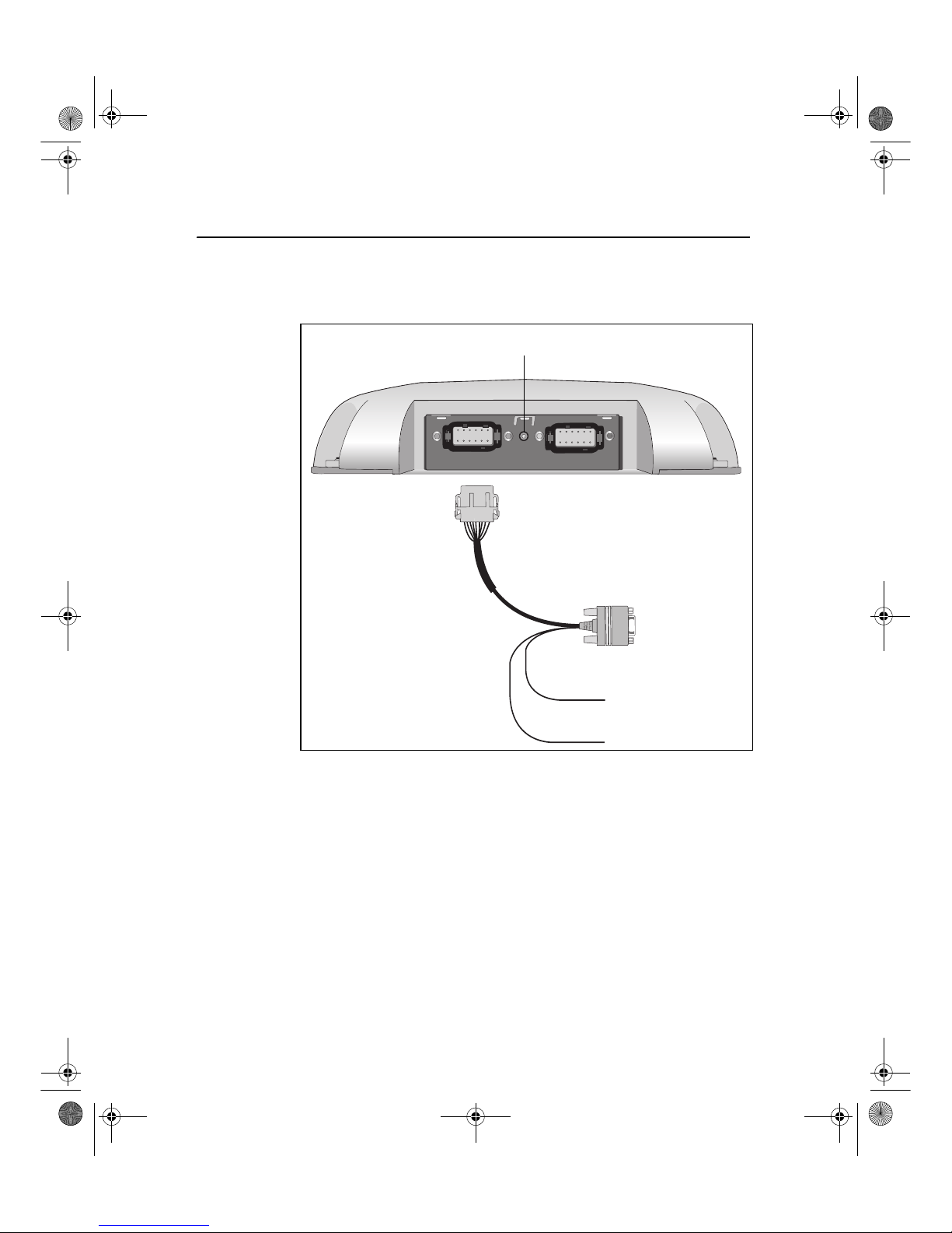
Figure 3.1 shows how to connect the receiver to an external device
using the system level cable (P/N 50166).
Figure 3.1 Standard power/data cable connections
AgGPS 252 receiver
AgGPS 252 receiver
DB9
cable (P/N 50166)
Ground –ve
Power +ve
Deutsch 12-pin
LED indicator
Port A Port B
System level
To external
device
Ag252_100A_UserGde_ENG.book Page 22 Wednesday, January 28, 2004 5:42 PM
Page 29

AgGPS 252 Receiver User Guide 23
Installing the Receiver 3
When routing the cable from the receiver to the external device, avoid:
• sharp objects
• kinks in the cable
• hot surfaces (exhaust manifolds or stacks)
• rotating or moving machinery parts
• sharp or abrasive surfaces
• door and window jams
• corrosive fluids or gases
Note – Do not bend the cable at the Deutsch connector. When you
secure the cable, use the supplied P-Clip. The P-Clip provides
additional support to the connectors and reduces the risk of damage.
When the cable is safely routed and connected to the receiver, use
tie-wraps to secure it at several points, particularly near the base of the
receiver, to prevent straining the connection. Coil any slack cable,
secure it with a tie-wrap, and tuck it into a safe place.
The external device may have to be configured to work with the
AgGPS 252 receiver. The configuration tools for the external device
should be provided with the device. For more information about
configuring the receiver, see Chapter 4. For information about
connecting a particular external device, refer to the manual for that
device or contact your local Trimble Reseller.
Note – Use a connector plug (P/N 51062) to cover Port B when that
port is not in use. For example, cover Port B when you are using the
receiver in a non-RTK mode.
Ag252_100A_UserGde_ENG.book Page 23 Wednesday, January 28, 2004 5:42 PM
Page 30

3 Installing the Receiver
24 AgGPS 252 Receiver User Guide
3.5 Connectors and Pinouts
Use the following pinout information if you need to wire a cable for
use with the AgGPS 252 receiver.
Figure 3.2 AgGPS 252 receiver port pinout
213456
789101112
Ag252_100A_UserGde_ENG.book Page 24 Wednesday, January 28, 2004 5:42 PM
Page 31

AgGPS 252 Receiver User Guide 25
Installing the Receiver 3
35.1 Port A
Port A on the receiver has a 12-pin Deutsch DTM connector. For
cables, use the mating connector, Deutsch part number DTM06-12SA.
Viewed from outside the receiver, the Port A connector is on the left. It
is the port that is typically used to connect to an Autopilot system.
Ta ble 3.3 Port A pinout
Pin Name/Function Comments
1 CAN A High I/O
2 Port 1 RS232 Tx OUT When held to ground during power up,
puts unit into Monitor mode
3 Port 1 RS232 Rx IN
4 PPS OUT
5 Signal GND Used for RS232 and other signals.
Should not be connected to
V– (battery negative)
6 Port 1 RTS OUT
7 Event OUT / Alarm OUT
8 Port 1 CTS IN
9 Event IN
10 V+ IN
11 V- IN
12 CAN A Low I/O
Ag252_100A_UserGde_ENG.book Page 25 Wednesday, January 28, 2004 5:42 PM
Page 32

3 Installing the Receiver
26 AgGPS 252 Receiver User Guide
35.2 Port B
This port has the same connector as Port A, see above. Viewed from
outside the receiver, the Port B connector is on the right. It is the port
that is typically used to connect to the SiteNet 900 radio.
Ta ble 3.4 Port B pinout
Pin Name/Function Comments
1 CAN B High I/O
2 Port 2 RS232 Tx OUT
3 Port 2 RS232 Rx IN
4 PPS OUT
5 Signal GND Used for RS232 and other signals.
Should not be connected to V–
(battery negative)
6 Port 2 RTS OUT
or Port 3 RS232 Tx OUT
7 Event OUT / Alarm OUT
8 Port 2 CTS IN or Port 3
RS232 Rx IN
9Event IN
10 V+ IN / OUT Maximum output current = 1.25 A
11 V– IN / OUT Maximum output current = 1.25 A
12 CAN B Low I/O
Ag252_100A_UserGde_ENG.book Page 26 Wednesday, January 28, 2004 5:42 PM
Page 33

CHAPTER
4
AgGPS 252 Receiver User Guide 27
Configuring the Receiver 4
In this chapter:
Introduction
AgRemote Home Screen
Configuring Differential GPS
Configuring the AgGPS 252 Receiver to Operate in RTK Mode
Configuring the Communication Ports
Ag252_100A_UserGde_ENG.book Page 27 Wednesday, January 28, 2004 5:42 PM
Page 34

4 Configuring the Receiver
28 AgGPS 252 Receiver User Guide
4.1 Introduction
Use either the Autopilot interface or the Trimble AgRemote utility to
change configuration settings in the AgGPS 252 receiver. You will
need to configure the receiver if you connect to a third-party device,
for example.
•If a Trimble AgGPS Autopilot system is configured to use an
AgGPS 252 receiver, and the port on the receiver is set to
8-N-1 38.4 K, the Autopilot system automatically configures
the receiver.
• The AgRemote utility is available from the Trimble website
(www.trimble.com). This chapter describes how to use the
utility to perform some common configurations.
Note – OmniSTAR VBS and HP are subscriber services that need to be
activated. For more information, see OmniSTAR, page 31.
Ag252_100A_UserGde_ENG.book Page 28 Wednesday, January 28, 2004 5:42 PM
Page 35
AgGPS 252 Receiver User Guide 29
Configuring the Receiver 4
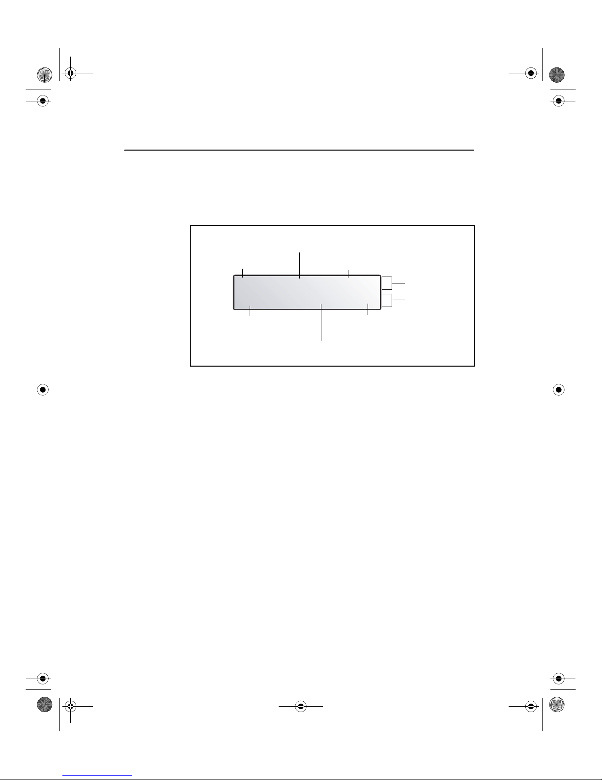
4.2 AgRemote Home Screen
Figure 4.1 shows the AgRemote Home screen when WAAS
corrections are being received.
Figure 4.1 AgRemote Home screen
For more information about these fields and how they change as you
change GPS mode, refer to the document called AgRemote Software
on the Trimble website (www.trimble.com) or contact your local
Trimble Reseller.
D/3D í07 DOP03
WAAS 122 ÷ø04
Correction type
DGPS satellite name or ID
Signal-to-Noise ratio
of DGPS satellite
Current PDOP value
Position type
Number of GPS satellites being tracked
GPS indicators
Correction
indicators
Ag252_100A_UserGde_ENG.book Page 29 Wednesday, January 28, 2004 5:42 PM
Page 36

4 Configuring the Receiver
30 AgGPS 252 Receiver User Guide
4.3 Configuring Differential GPS
For the receiver to output GPS position coordinates of submeter
accuracy, you must first select a differential signal from one of the
following sources:
• WAAS/EGNOS – free service, limited availability
The Wide Area Augmentation System (WAAS) augments GPS
with additional signals for increasing the reliability, integrity,
accuracy, and availability of GPS in the United States. The
European Geostationary Navigation Overlay System (EGNOS)
is the European equivalent of WAAS.
• OmniSTAR – paid subscription, available worldwide
You can use this paid service as an alternative to
WAAS/EGNOS. It provides over-the-air DGPS activation.
For more information, see Differential GPS positioning (DGPS),
page 11.
Ag252_100A_UserGde_ENG.book Page 30 Wednesday, January 28, 2004 5:42 PM
Page 37

AgGPS 252 Receiver User Guide 31
Configuring the Receiver 4
43.1 OmniSTAR
The AgGPS 252 receiver can use OmniSTAR corrections. To do this,
you need to configure the receiver and purchase an OmniSTAR
subscription.
Note – To track the OmniSTAR satellite, the receiver must be outside
with a clear view of the sky, turned on, and configured to receive
OmniSTAR VBS or HP corrections.
To use the AgRemote utility to activate an OmniSTAR subscription:
1. Connect the AgGPS 252 receiver to the computer. Turn on the
receiver and start the AgRemote utility. For instructions on how
to use AgRemote, refer to the AgRemote documentation.
2. In AgRemote, select Configuration / DGPS Config.
3. Set the Source Select field to one of the following:
– Omnistar HP
– Omnistar VBS
4. Set the EZ Sat: Omni* field to the area you are operating in. For
example, if you are working in California, select N. America
West.
5. Press 4 then 5 to complete the procedure.
6. Obtain an OmniSTAR licence from OmniSTAR. All licenses
are activated over the air. Contact OmniSTAR on
1-888-883-8476 (USA or Canada) and provide the following
details:
– your billing information
– serial number
– satellite beam name
OmniSTAR will activate the receiver. Activation can take
5–30 minutes.
Ag252_100A_UserGde_ENG.book Page 31 Wednesday, January 28, 2004 5:42 PM
Page 38

4 Configuring the Receiver
32 AgGPS 252 Receiver User Guide
40.1W AAS/EGNOS
WAAS is a free satellite-based DGPS service that is available only in
North America; EGNOS is a free satellite-based DGPS service that is
available only in Europe.
To use the WAAS/EGNOS DGPS signal, you must first configure the
receiver.
1. Connect the AgGPS 252 receiver to the computer. Turn on the
receiver and start the AgRemote utility.
2. In AgRemote, select Configuration / DGPS Config.
3. Set the Source Select field to WAAS.
4. Press 4 then 5 to complete the procedure.
To enable WAAS reception in the field:
1. Take the receiver outside. Make sure that it has a clear southeast
and southwest view of the sky.
2. Turn on the receiver. WAAS activation can take two or more
minutes. Once activation succeeds, the Home screen displays
D/3D.
Ag252_100A_UserGde_ENG.book Page 32 Wednesday, January 28, 2004 5:42 PM
Page 39

AgGPS 252 Receiver User Guide 33
Configuring the Receiver 4
4.1 Configuring the AgGPS 252 Receiver to Operate in
RTK Mode
Use the AgRemote utility to configure the AgGPS 252 receiver for
operation in RTK mode. To configure the receiver:
1. Connect the AgGPS 252 receiver to the computer. Turn on the
receiver and start the AgRemote utility.
2. In AgRemote, select Configuration / DGPS Config.
3. Set the Source Select field to RTK.
4. Press 4 then 5
to complete this part of the procedure.
5. For RTK operation, connect the radio to a port. Change the port
input settings for that port to RtkLnk.
4.1 Configuring the Communication Ports
If the AgGPS 252 receiver is to be connected to an external device,
configure Ports A and B so that the proper data type is input to and
output from the receiver.
To configure Port A:
1. Connect the AgGPS 252 receiver to the computer. Turn on the
receiver and start the AgRemote utility.
2. In AgRemote, select Configuration / Port A Config.
3. Use the menu commands to configure the communication ports.
Ensure that the receiver outputs the correct GPS position data
type for the hardware device or software program that is
connected to the receiver.
To configure Port B:
• Repeat the above steps but in Step 2 select Configuration / Port
B Config.
Ag252_100A_UserGde_ENG.book Page 33 Wednesday, January 28, 2004 5:42 PM
Page 40

4 Configuring the Receiver
34 AgGPS 252 Receiver User Guide
40.1 Configuring input/output communication
The port input and output settings appear in the first screen. In
Figure 4.2, the port is set to accept TSIP inputs at a baud rate of
115,000 with a parity of 8-Odd-1. The outputs are TSIP, also at a baud
rate of 115,000.
Figure 4.2 Communication settings
Configure the Port Input/Output communication settings for
communicating with the AgGPS Autopilot, other external hardware
devices, and software programs. Table 4.1 describes the input settings.
Ta ble 4.1 Port input settings
Setting Description
None Inputs nothing to the receiver.
TEXTB The receiver can accept ASCII data from an external device,
such as a chlorophyll meter, on Port A, merge it with NMEA GPS
data, and output the combined data on Port B. The incoming data
must be limited to 66 ASCII characters and terminated by a
carriage return and line feed (hex characters 0x0D 0x0A). The
NMEA string outputs as $PTNLAG001,<up to 66 ASCII
characters>*<2 digit checksum><CR><LF>. For the receiver to
output the combined NMEA string, NMEA must be selected as
the output protocol on Port B.
Ag252_100A_UserGde_ENG.book Page 34 Wednesday, January 28, 2004 5:42 PM
Page 41

AgGPS 252 Receiver User Guide 35
Configuring the Receiver 4
The default port settings are:
Note – The AgRemote utility, when connected to an AgGPS 252
receiver, automatically resets the receiver port communication settings
to 8-O-1 TSIP 115 K. This enables optimal communication with an
office computer. If the receiver is to work with an Autopilot system,
however, the receiver port communication settings must be 8-N-1 TSIP
38.4 K. To work with some other devices and software programs, the
receiver port communication settings must be 8-N-1 NMEA 4800. If
AgRemote has changed the settings, you will need to change them
back manually.
TEXTA See the description for the TEXTB setting (above). TEXTA input
outputs text on Port A. The default port settings are 8-N-1 TSIP
38.4 K. These may vary by product.
RTCM The receiver can accept RTCM data from an external DGPS
device, such as an external radio.
TSIP The receiver can accept or output TSIP data packets from the
port when using the optional AgRemote program or using the
AgGPS 170 Field Computer.
RtkLnk The receiver can accept real-time corrections (CMR data) from
an external device such as a Trimble radio.
Port A Port B
Baud rate In TSIP 38,400 TSIP 38,400
Out TSIP 38,400 TSIP 38,400
Data bits 88
Parity None None
Stop bits 11
Table 4.1 Port input settings (continued)
Setting Description
Ag252_100A_UserGde_ENG.book Page 35 Wednesday, January 28, 2004 5:42 PM
Page 42

4 Configuring the Receiver
36 AgGPS 252 Receiver User Guide
When using a Trimble SiteNet 900 radio, make sure that the
communication settings are correct in the receiver.
The default settings to use with the SiteNet radio are:
Changing the input or output port settings
1. From the Port A Config screen, press 2 until the Port-A
Input/Output screen appears:
2. Press 3 to activate the cursor.
3. Press 1 or 2 to change the value.
4. Press 3.
5. Repeat Steps 3 and 4 until you have set all the required values.
6. Press 4 to save all the changes.
7. Press 2 to move to the next screen.
Setting Description
Baud rate 38,400
Data bits 8
Parity None
Stop bits 1
åæ I RTCM 9600
8N1 0 NMEA 4800
Ag252_100A_UserGde_ENG.book Page 36 Wednesday, January 28, 2004 5:42 PM
Page 43

AgGPS 252 Receiver User Guide 37
Configuring the Receiver 4
NMEA settings
Three screens (NMEA1, NMEA2, and NMEA3) show what NMEA
messages are output from the port. Message types shown in upper case
are being output; message types shown in lower case are not.
For more information about NMEA message types, refer to the
document called NMEA-0183 Messages Guide for AgGPS Receivers
on the Trimble website (www.trimble.com).
Port output rate
This setting can be used to vary the NMEA and TSIP output rate. A
setting of 1 outputs one position each second.
ASAP equals the rate selected on the Filter and Position Rate screen
under the GPS Config menu. A setting of ASAP outputs positions five
or ten times every second. The default (factory) setting is 1 Hz.
Ag252_100A_UserGde_ENG.book Page 37 Wednesday, January 28, 2004 5:42 PM
Page 44

4 Configuring the Receiver
38 AgGPS 252 Receiver User Guide
Ag252_100A_UserGde_ENG.book Page 38 Wednesday, January 28, 2004 5:42 PM
Page 45

CHAPTER
5
AgGPS 252 Receiver User Guide 39
Troubleshooting 5
In this chapter:
Introduction
Problems and Solutions
Troubleshooting Flowcharts
Ag252_100A_UserGde_ENG.book Page 39 Wednesday, January 28, 2004 5:42 PM
Page 46

5 Troubleshooting
40 AgGPS 252 Receiver User Guide
5.1 Introduction
This chapter describes some problems that can arise and explains how
to solve them. It includes a series of flowcharts to help with
troubleshooting.
As you work through this chapter, you may need to view the receiver
status or change values in some fields. For information on how to do
this, refer to the document called NMEA-0183 Messages Guide for
AgGPS Receivers. This document is on the Trimble website
(www.trimble.com).
5.2 Problems and Solutions
Should problems arise, try the following solutions.
Ag252_100A_UserGde_ENG.book Page 40 Wednesday, January 28, 2004 5:42 PM
Page 47

AgGPS 252 Receiver User Guide 41
Troubleshooting 5
Global Positioning System (GPS)
Problem Possible solution
Poor accuracy
The accuracy of GPS positions is
poor because the receiver is picking
up poor quality signals from the
satellites.
The receiver always calculates the
most accurate position it can, given
the current GPS satellite differential
operating conditions.
Change some or all of the following GPS settings:
• Minimum elevation – Increase the setting
(the default is 8°).
• Minimum Signal Strength – Increase the System
Mask AMU setting (the default is 3).
• Maximum PDOP – Decrease the setting
(the default is 13).
• GPS Mode – Change to Manual 3D
(the default is Auto 2D/3D).
• DGPS Mode – Change to DGPS
(the default is DGPS Auto/On/Off).
GPS signals are reflecting off nearby
trees and/or metal buildings and
horizontal surfaces.
To reduce multipath noise, mount the GPS receiver
so that it has a clear view of the sky. The receiver
must be away from trees and large metal objects.
Intermittent loss of lock on
satellite
The receiver loses the satellite
signal from time to time.
Make sure that the receiver is mounted on the
highest point of the vehicle and is clear of metal
surfaces.
Check Maximum PDOP and Minimum Signal
Strength settings (see Poor accuracy, above).
Intermittent DGPS signal
The correction signal strength can
drop to unusable levels. Causes
include tree canopy cover between
the receiver and the differential
satellite, radar sets, and microwave
transmitters.
Move the receiver away from the tree cover and/or
from sources of electromagnetic interference.
Ag252_100A_UserGde_ENG.book Page 41 Wednesday, January 28, 2004 5:42 PM
Page 48

5 Troubleshooting
42 AgGPS 252 Receiver User Guide
Tracking but not receiving a
differential signal
The receiver is tracking satellites
and tracking an OmniSTAR satellite
beam, but is not receiving DGPS
signals. The Home screen indicates
how many satellites are being
tracked, and whether a differential
source is being tracked.
You see :
h-3D for HP not converged
H-3D for HP converged
r-3D for RTK float
R-3D for RTK fixed
D-3D for DGPS
HP and RTK also give an indication
of positional accuracy on the Home
screen (AgRemote).
Check that your DGPS service subscription is still
current and enabled.
For OmniSTAR service:
1. Use the AgRemote utility to navigate to one of the
following screens, depending on what you are
using:
•the Omni HP Info screen
•the Omni VBS Info screen.
2. Press
4 until Stop Date appears.
If the message Access Unknown appears, contact
OmniSTAR to reactivate your subscription. F or more
information, see OmniSTAR, page 31.
The receiver must be switched on and configured to
track the correct satellite coverage beam before it
can be reactivated.
The receiver automatically tracks the correct beam
based on receiver geographic location. If the
receiver is manually changed, automatic tracking is
deactivated until you perform a hard reset or
firmware flash.
When a satellite subscription is activated, the Home
screen displays D/3D .
Problem Possible solution
Ag252_100A_UserGde_ENG.book Page 42 Wednesday, January 28, 2004 5:42 PM
Page 49

AgGPS 252 Receiver User Guide 43
Troubleshooting 5
No GPS position output from the
receiver after connecting to
AgRemote
When the receiver is connected to
the AgRemote utility, AgRemote
automatically resets the port
communication settings on the
receiver to 8-O-1 TSIP 115 K for
both input and output. This enables
optimal communication with an office
computer.
If the receiver is to work with an
Autopilot system, however, the
receiver port communication settings
must be 8-N-1 TSIP 38.4 K. To work
with some other devices and
software programs, the receiver port
communication settings must be
8-N-1 NMEA 4800. If AgRemote has
changed the settings, you will need
to change them back manually.
Connect AgRemote. Then reset the port
communication settings to NMEA output. For more
information, see Configuring the Communication
Ports, page 33.
Long time to initialize
In RTK mode, longer baselines
require longer initialization times.
(The baseline is the distance
between the base receiver and the
rover receivers.)
Wait for the receiv er to initialize or consider
repositioning the base receiver to shorten the
baseline. Make sure the rover is in a clear area.
Loss of initialization
In RTK mode initialization can be
lost when the rover receiver is close
to trees or buildings and the number
of satellites falls below four.
Additionally, initialization may be lost
if the receiver has not been tracking
RTK corrections for some time. For
more information, see the next item.
Move away from trees and obstructions to initialize.
Once initialized, approach the obstructed area again.
If the obstructions are severe, GPS positioning may
not work in that area.
Because the GPS satellites move, there may be
times of the day when you are working in an area
with obstructions. For more information, see the
Trimble Planning software on the Trimble website
(www.trimble.com).
Problem Possible solution
Ag252_100A_UserGde_ENG.book Page 43 Wednesday, January 28, 2004 5:42 PM
Page 50

5 Troubleshooting
44 AgGPS 252 Receiver User Guide
Interference
Not tracking RTK corrections
The radio link is down or intermittent. • Ensure that the line-of-sight between the base
and rover receivers is not obstructed.
• Ensure that the rover receiver is within range of
the radio.
• Ensure that the radio power supply is on.
Problem Possible solution
Strong magnetic fields
Strong magnetic fields have no
effect on GPS or satellite DGPS
signals.
However , some computers and other
electric equipment radiate
electromagnetic energy that can
interfere with a GPS receiver.
If you suspect interference from a local magnetic
field, move the receiver away from, or turn off, the
suspect electronics while observing the number of
satellites being tracked on the receiver or the signalto-noise ratio (SNR) of the satellite. If the SNR goes
up when the electronics are turned off, there may be
interference from the local electronics.
FM 2-way radios
Transmitting FM 2-way radios can
interfere with OmniSTAR, WAAS,
and GPS signal reception.
Make sure that there is at least 1 m (3 ft) between
the FM 2-way radio antenna and the receiver.
Engine noise
An unshielded ignition system can
cause enough noise to block
reception of a differential signal.
Use resistor spark plug wires on the vehicle ignition
system.
Problem Possible solution
Ag252_100A_UserGde_ENG.book Page 44 Wednesday, January 28, 2004 5:42 PM
Page 51
AgGPS 252 Receiver User Guide 45
Troubleshooting 5
GPS receiver
An alternator can cause noise that
interferes with a differential signal.
Use bypass capacitors, commonly available in
automotive stores for cleaning up interference to CB
and other radios. If the problem persists, shield
engine components with aluminum foil.
Relocate the antenna on the machine.
Determine the optimal antenna location by watching
the SNR value on the AgRemote Home screen.
Note – Before replacing engine parts in an attempt
to solve this problem, make sure that the problem is
not caused by a computer or power source near the
receiver. Some computers and their power sources
cause noise that disrupts GPS and satellite DGPS
signals.
Problem Possible solution
Mounting location
The receiver is not picking up a clear
signal.
Mount the receiver on the centerline of the vehicle,
away from any sources of interference and with a
clear view of the sky (see Choosing a location,
page 19).
Cables
One of the cables seems faulty . Use an ohmmeter to check the cable. The resistance
of a good cable between connector pins at each end
of the cable is zero.
If the cable is sound, but the problem persists, try
exchanging the cable with one that you know is
working.
If the cable is defective, contact your local Trimble
Reseller for an RMA number (if the Trimble product
is still under warranty), or to purchase a replacement
cable.
Problem Possible solution
Ag252_100A_UserGde_ENG.book Page 45 Wednesday, January 28, 2004 5:42 PM
Page 52

5 Troubleshooting
46 AgGPS 252 Receiver User Guide
AgRemote utility
Real-time clock battery
A lithium-ion battery in the receiver
powers the internal real-time clock
and so enables the receiver to get a
first fix faster. The battery has a life
of 7.5 years. When th e battery fails,
the internal clock cannot keep
accurate time and the receiver may
take longer to output GPS positions.
Please contact your local Trimble Reseller to get
the batteries replaced. You cannot replace the
battery yourself.
Factory defaults
You ne ed to restore the receiver
factory defaults.
To restore receiver factory default settings:
1. Conne ct the receiver to a computer. Turn on the
receiver.
2. Run th e AgRemote utility.
3. Navigate to the Clear BB RAM screen.
4. Press
2 until Yes appears.
5. Press 4.
The factory default settings are restored. The DGPS
service subscription is not lost.
Problem Possible solution
AgRemote cannot communicate with
the receiver. All you see is a blank
screen.
1. Make sure that:
• the receiver is connected to a 12–32 V DC power
source
• all cable connections between the receiver and
the computer are secure
• you are using the correct COM port
2. Turn off the receiver then turn it on again.
3. Select File / Connect.
Problem Possible solution
Ag252_100A_UserGde_ENG.book Page 46 Wednesday, January 28, 2004 5:42 PM
Page 53
AgGPS 252 Receiver User Guide 47
Troubleshooting 5
FlashLoader 200 upgrade utility
Problem Possible solution
The FlashLoader 200 upgrade utility
cannot detect the receiver or
download the firmware.
Make sure that:
• Other programs, such as AgRemote and
Microsoft® ActiveSync® technology , are not using
the COM port that the computer is using.
• The receiver is connected to a 12–32 V DC
power source.
• All cables are connected correctly between the
device and the computer.
• The receiver is connected to the correct computer
COM port. To do this:
1. From the FlashLoader 200 menu, select
Settings.
2. Select the check box for a serial link.
3. At Port, select Auto. Click OK.
4. Select the Upload firmware to receiver check
box.
5. Navigate to where the firmware file is saved
and select the file. Click Proceed.
6. From the Auto Port Select dialog, select Use
receiver on port... and click OK.
Once you have checked this, turn off the receiver
then turn it on again. Try again to connect
FlashLoader 200.
Ag252_100A_UserGde_ENG.book Page 47 Wednesday, January 28, 2004 5:42 PM
Page 54

5 Troubleshooting
48 AgGPS 252 Receiver User Guide
5.1 Troub leshooting Flowcharts
These flowcharts describe how to troubleshoot problems in the
following areas:
• system hardware and power
• GPS reception (no third-party device attached)
• GPS reception (third-party device attached)
• OmniSTAR positioning
• RTK (using the AgRemote utility)
In addition, you may find it useful to review Chapter 3, Installing the
Receiver.
Ag252_100A_UserGde_ENG.book Page 48 Wednesday, January 28, 2004 5:42 PM
Page 55

AgGPS 252 Receiver User Guide 49
Troubleshooting 5
Figure 5.1 Troubleshooting system hardware and power
START HERE
The receiver is connected
and has sufficient power
for operation.
Is the receiver LED
or AgRemote
screen on?
Is the data/power cable
securely connected to
the receiver antenna?
Connect the red and
black power leads of
the data/power cable to
machine 10-32 V DC
power.
Is the receiver or
AgRemote screen
light on?
Yes
Continue
No
No
Can you turn on
the machine
(combine or tractor)?
No
No
There may be a fault
with the machine
power. Contact your
local farm implement
dealer.
Yes
Recheck the
data/power cable
connections. If the
problem persists,
contact your local
Trimble Reseller.
Is the LED on?
No
The receiver has insufficient
power. Contact your local
Trimble Reseller.
Yes
Yes
Yes
Check the battery
power. Is the battery
voltage between
10-32 volts?
Yes
Ag252_100A_UserGde_ENG.book Page 49 Wednesday, January 28, 2004 5:42 PM
Page 56

5 Troubleshooting
50 AgGPS 252 Receiver User Guide
Figure 5.2 Using AgRemote to troubleshoot GPS reception (no third-party device attached)
S
T
A
R
T
H
E
R
E
Yes
Yes
No
Continue
No
Yes
No
Is the AgRemote
screen on?
Check the Home
screen for GPS
reception. Is the
receiver tracking at
least 4 satellites?
Yes
Does the Home
screen display D/3D
(for a 3D position)?
Yes
The GPS reception
appears to be working
correctly. If the problem
persists, contact your
local Trimble Reseller.
See the system
hardware and power
flowchart. When GPS
satellite reception is
resolved. Return to this
flowchart.
No
Make sure that the
receiver/antenna is
located with a clear
view of the sky.
Are you receiving
satellites now?
No
See the OmniSTAR VBS or
RTK flowcharts.
If the problem persists,
contact your local
Trimble Reseller.
No
Restore GPS
default values.
Turn off the machine
engine (combine or tractor)
but maintain power to the
GPS receiver.
Return to the Home screen
and check GPS reception.
Is the receiver tracking at
least 4 satellites?
Return to the Home
screen and check
GPS reception.
Is the receiver
tracking at least 4
satellites?
No
Yes
Turn on the machine engine
and check the Home
screen. Do the satellites
disappear?
The GPS reception appears
to be working correctly. If
the problem persists,
contact your local Trimble
Reseller.
The problem is unresolved.
Contact your local Trimble
Reseller.
The problem may be
caused by excessive
engine noise.
For information on
reducing engine noise,
see Chapter 3.
If the problem persists,
contact your local
Trimble Reseller.
Yes
Ag252_100A_UserGde_ENG.book Page 50 Wednesday, January 28, 2004 5:42 PM
Page 57

AgGPS 252 Receiver User Guide 51
Troubleshooting 5
Figure 5.3 Using AgRemote to troubleshoot GPS reception (third-party device attached)
S
T
A
R
T
H
E
R
E
Yes
Yes
Yes
No
Yes
No
No
No
Yes
No
Continue
Yes
Continue
Yes
No
No
Continue
No
No
Yes
Is the AgRemote
screen on?
Is the text visible on
the receiver or
AgRemote screen?
Check the Home screen
for GPS reception. Is the
receiver tracking at least
4 satellites?
If applicable, does the
device display DG
(for a 3D position)?
Make sure that the
cable is securely
connected from the
device to the receiver.
Your GPS reception
appears to be
working correctly. If
the problem persists,
contact your local
Trimble Reseller.
See the system
hardware and power
flowchart.
When the GPS
reception is resolved,
return to this flowchart.
Make sure that the
receiver/antenna is
located with a clear
view of the sky.
Is the receiver now
tracking at least
4 satellites?
Check that the receiver
is configured correctly
for input/output
communications.
Does the device
display DG?
Contact your local
Trimble Reseller.
Restore GPS
default values.
Return to the Home
screen and check
GPS reception.
Are you receiving at
least 4 satellites?
See the OmniSTAR VBS
or RTK flowchart.
If the problem persists,
contact your local Trimble
Reseller.
Does the receiver
Home screen
display D/3D?
The data/power cable
may be faulty. Contact
your local Trimble
Reseller.
Turn off the machine engine
(combine or tractor) but
maintain power to the GPS
receiver. Wait five minutes.
Return to the Home screen
and check GPS reception.
Is the receiver tracking at
least 4 satellites?
Turn on the machine engine
and check the Home
screen. Do the satellites
disappear?
Your GPS reception
appears to be working
correctly. If the problem
persists, contact your local
Trimble Reseller.
The problem
is unresolved.
Contact your local
Trimble Reseller.
The problem may be
caused by excessive
engine noise.
For information on
reducing engine noise,
see Chapter 3.
If the problem persists,
contact your local
Trimble Reseller.
Yes
Yes
No
Ag252_100A_UserGde_ENG.book Page 51 Wednesday, January 28, 2004 5:42 PM
Page 58

5 Troubleshooting
52 AgGPS 252 Receiver User Guide
Figure 5.4 Using AgRemote to troubleshoot OmniSTAR positioning
S
T
A
R
T
H
E
R
E
Yes
No
No
Yes
Yes
No
Yes
Check the AgRemote
Home screen for GPS
reception. Is the
receiver tracking at
least 4 satellites?
Does the AgRemote
Home screen display
S for DGPS satellite
mode?
Make sure that your
OmniSTAR subscription
service is current,
activated, and correctly
configured.
If the problem
persists, contact
your local Trimble
Reseller.
Continue
No
No
See the GPS reception
flowchart. When GPS
satellite reception is
resolved, return to this
flowchart.
Wait one minute.
Does the receiver or
AgRemote Home
screen now display
D/3D (3D position)?
The system appears
to be working
correctly. If the
problem persists,
contact your local
Trimble Reseller.
Check the Home
screen for satellite
signal strength. Is the
S/N (signal to noise
ratio) 6 or more?
Check the Omni* VBS
Info screen. Press 4. Is
OmniSTAR enabled?
Press 4 until you see
Stop and a date.
Has the date expired?
The OmniSTAR almanac
may be out of date. Set up
the receiver and track
satellites for 1-2 hours to
acquire a new almanac.
If the problem persists,
contact your local Trimble
Reseller.
Turn on the machine
engine and check the
Home screen. Do the
satellites disappear?
Something may be
interfering with the
OmniSTAR satellite signal.
Check the Age of DGPS /
Age of Synch screen. Is the
DGPS age 10 or more? Is
the Synch age 3 or less?
Press 4 again to check
OmniSTAR status.
Do you see either of the
following messages?
Received Data
No Recent Data
Is the status message
one of the following?
Init Decoder (1-4)
Decoder Ready
Access Confirmed
The received or old data
is not sufficient for good
DGPS positioning.
Contact OmniSTAR.
Contact your local
Trimble Reseller.
Turn off the machine
engine (combine or tractor)
but maintain power to the
GPS receiver. Wait
five minutes.
Return to the Home screen
and check GPS reception.
Are you receiving at least
4 satellites?
The problem is unresolved.
Contact your local
Trimble Reseller.
The problem may be
caused by excessive
engine noise.
For information on reducing
engine noise,
see Chapter 3.
If the problem persists,
contact your local
Trimble Reseller.
The receiver is tracking
GPS satellites but not
receiving the OmniSTAR
signal. Contact your local
Trimble Reseller.
No
Continue
Yes
No
No
Yes
Yes
No
No
Yes
Yes
Yes
No
No / Not sure
Ag252_100A_UserGde_ENG.book Page 52 Wednesday, January 28, 2004 5:42 PM
Page 59

AgGPS 252 Receiver User Guide 53
Troubleshooting 5
Figure 5.5 Using AgRemote to troubleshoot RTK
START HERE
Check that there are
no other base stations
operating in the area,
interfering with your
base station signal.
Check the AgRemote Home
screen for GPS reception. Is
the receiver tracking at least 4
satellites?
See the GPS Reception
Troubleshooting Guide.
When GPS satellite
reception is resolved, return
to this guide.
Move the roving receiver to a
place where there is a clear
line of sight between it and
the base station. Are RTK
corrections being received
now? Does the AgRemote
screen display r or R?
No
Check the power supply to
the base station and the base
radio. Is the base transmit
light on?
Provide power to the
base station and radio.
Check that the receiver is
initialized. Does the
AgRemote Home screen
display R for a fixed
solution?
Are 5 or more satellites
being tracked?
Yes
Move the receiver away from
any obstructions so that it
can track at least 5 satellites.
Receiver is operating
normally.
Receiver should initialize
soon (wthin 30 seconds for
baselines under 5 km). After
30 seconds does the Home
screen display R for a fixed
solution?
Something may be interfering
with the GPS signal. See the
GPS Reception Trouble-
Shooting Guide. Is the
problem still unresolved?
Continue
No
Yes
Check that the receiver is
receiving RTK corrections.
The age on Home screen
should be 1 if receiving
radio. Does the AgRemote
Home screen display r or R
for an RTK solution?
No
No
No
Yes
No
No
Yes
Check the Rover receiver
light to ensure RTK
corrections are present. Is the
LED flashing yellow?
No
No CMR corrections are being
received. In the Config screens
use RTK link to make sure that
the rover radio parameters are
the same as the base radio
parameters. Are CMR
corrections being recieved now?
Yes
No
Yes
Check the AgRemote screen
for RTK status and contact
your local Trimble Reseller.
Yes
Receiver is operating
normally.
Yes
Is the RTK option installed in
the receiver?
Yes
No
Obtain and install the RTK
option
Yes
Yes
Ag252_100A_UserGde_ENG.book Page 53 Wednesday, January 28, 2004 5:42 PM
Page 60

5 Troubleshooting
54 AgGPS 252 Receiver User Guide
Ag252_100A_UserGde_ENG.book Page 54 Wednesday, January 28, 2004 5:42 PM
Page 61

APPENDIX
A
AgGPS 252 Receiver User Guide 55
Specifications A
A.1
AgGPS 252 Receiver
Table A.1 lists the physical characteristics of the AgGPS 252
combined GPS/DGPS receiver and antenna.
Table A.1 AgGPS 252 receiver
Item Description
Size 300 mm (11.7 in) wide x 309 mm (12.05 in) deep x 70 mm
(2.73 in) high
Weight 2.1 kg
Power Nominal 350 mA at 12 V DC
Operating temperature –30 °C (–22 °F) through +70 °C (+158 °F)
Storage temperature –40 °C (–40 °F) through +85 °C (+185 °F)
Humidity Complies with Mil 810E Method 507.3 Procedure III Aggravated
Cyclic Humidity.
Ten 24 hour cycles of constant 95% RH, with cycling
temperature and dwells +30 °C (+86 °F) and +60 °C (140 °F).
Unit sealed to +/- 5 PSID
Casing Low-profile UV-resistant plastic. Dust-proof, waterproof, shock
resistant, with recessed protected connectors.
Ag252_100A_UserGde_ENG.book Page 55 Wednesday, January 28, 2004 5:42 PM
Page 62

A Specifications
56 AgGPS 252 Receiver User Guide
A.2 GPS Channels
Table A.2 lists the performance characteristics of GPS channels.
Connectors 12-pin Deutsch connectors
Ports Two connection ports, both of which support RS-232 and CAN
Mounting Three holes for 10 mm (0.39 in) bolts
Compliance FCC Part 15 Class A, C-Tick, E-mark,
CE-mark
T ab l e A.2 GPS channels performance
Item Description
General 12-channel, parallel tracking L1 1571.42 MHz and L2
1227.60 MHz. C/A code and carrier phase filtered measurement.
Update rate 1, 5, 10 Hz
RTK speed accuracy 0.16 kph (0.10 mph)
RTK position accuracy Horizontal 2.5 cm (0.98 in) + 2 ppm, 2 sigma, and vertical 3.7 cm
(1.46 in) + 2 ppm, 2 sigma, if all of the following criteria are met:
• At least 5 satellites
•PDOP <4
• CMR corrections
• Standard format broadcast from a Trimble MS750, AgGPS 214,
or equivalent reference station
Differential speed
accuracy
0.16 kph (0.1 mph)
Table A.1 AgGPS 252 receiver (continued)
Ag252_100A_UserGde_ENG.book Page 56 Wednesday, January 28, 2004 5:42 PM
Page 63

AgGPS 252 Receiver User Guide 57
Specifications A
Differential position
accuracy
Less than 1 m (3.28 ft) horizontal if all of the following criteria are
met:
• At least 5 satellites
•PDOP <4
• RTCM SC-104 corrections
• Standard format broadcast from a Trimble MS750, AgGPS 214,
or equivalent reference station
OmniSTAR HP speed
accuracy
0.16 kph (0.1 mph)
OmniSTAR HP position
accuracy
10 cm (3.94 in) after convergence, 2 sigma, if all the following
criteria are met:
• At least 5 satellites
•PDOP <4
• OmniSTAR HP corrections
Convergence time can vary, depending on the environment.
Time to the first fix (submeter accuracy) is typically
<30 seconds; time to the first useable fix (<10 cm accuracy) is
typically <30 minutes.
Time to first fix <30 seconds, typical
Multipath mitigation EVEREST technology
Satellite differential
compatibility
OmniSTAR, WAAS, and EGNOS
NMEA messages GGA 1 1
1
, GLL, GSA1, GST, GSV, GST, MSS, PTNLDG, PTNL
PJK, PTNL PJT, PTNL VGK, PTNL VHD, PTNLEV, PTNLID,
PTNLSM, RMC1, VGK, VTG1, XTE, ZDA
1
By default, the receiver is configured to output GCA, GSA, RMC, and VTG messages at a 1Hz (1 position per second)
update rate.
Table A.2 GPS channels performance (continued)
Ag252_100A_UserGde_ENG.book Page 57 Wednesday, January 28, 2004 5:42 PM
Page 64

A Specifications
58 AgGPS 252 Receiver User Guide
A.3 L-Band Satellite Differential Correction Receiver
Table A.3 lists the characteristics of the L-band satellite differential
correction receiver with OmniSTAR support.
A.4 Receiver Default Settings
Table A.4 lists the receiver default settings.
Table A.3 L-Band satellite differential correction receiver with
OmniSTAR support
Item Description
Bit error rate 10
-5
for Eb/N of >5.5 dB
Acquisition and reacquisition time <5 seconds, typical
Frequency band 1525–1559 MHz
Channel spacing 0.5 kHz
Table A.4 Receiver default settings
Item Description
DGPS source WAAS/EGNOS
Dynamics Land
Minimum elevation 8°
AMU mask 3
PDOP mask 13
PDOP 2D/3D switch 11
DGPS mode Auto On/Off
DGPS correction age limit 250 seconds
Pos fix rate 1 Hz
Ag252_100A_UserGde_ENG.book Page 58 Wednesday, January 28, 2004 5:42 PM
Page 65

APPENDIX
B
AgGPS 252 Receiver User Guide 59
Third-Party Interface
Requirements
B
B.1
Third-Party Software
Table B.1 lists the interface requirements for connecting an AgGPS
receiver to third-party software.
Use cable P/N 50166, or 30945 plus 50581, when connecting to the
third-party software products listed.
Table B.1 Third-party software interface requirements
Software Company Protocol NMEA
messages
Baud Other Pos rate
AgView GIS Solutions NMEA VTG, GLL 4800 8-N-1 1Hz
FarmGPS Red Hen NMEA GGA, GSA, VTG 4800 8-N-1 1Hz
Field Rover SST Dev
Group
NMEA GGA, GSA, GSV,
VTG
4800 8-N-1 1Hz
FieldLink DOS Agris NMEA GGA, GSA, VTG 4800 or
9600
8-N-1 1Hz
FieldLink
Windows
Agris NMEA GGA, GSA, VTG 4800 or
9600
8-N-1 1Hz
Ag252_100A_UserGde_ENG.book Page 59 Wednesday, January 28, 2004 5:42 PM
Page 66

B Third-Party Interface Requirements
60 AgGPS 252 Receiver User Guide
Field Worker
Pro
Field Worker NMEA GGA, GLL, RMC,
VTG
4800 or
9600
8-N-1 1Hz
HGIS Starpal NMEA GGA, RMC 4800 or
9600
8-N-1 1Hz
Instant Survey Agrilogic
(Case-IH)
NMEA GGA, GSA, RMC 4800 8-N-1 1Hz
Pocket Survey Agrilogic
(Case-IH)
NMEA GGA, GSA, RMC 4800 8-N-1 1Hz
Sitemate Farmworks NMEA GGA, VTG 4800 8-N-1 1Hz
Table B.1 Third-party software interface requirements (continued)
Software Company Protocol NMEA
messages
Baud Other Pos rate
Ag252_100A_UserGde_ENG.book Page 60 Wednesday, January 28, 2004 5:42 PM
Page 67

AgGPS 252 Receiver User Guide 61
Third-Party Interface Requirements B
B.2 Third-Party Hardware
Table B.2 lists the interface requirements for connecting an AgGPS
receiver to third-party hardware.
Table B.2 Third-party hardware interface requirements
Hardware Company Protocol NMEA
messages
Baud Other Pos
rate
Cable P/N
AMS Raven NMEA GGA, VTG 9600 8-N-1 1Hz
50166, or
30945
plus
50581
Ag
Navigator
Springhill RTCM 9600 8-N-1 10Hz
Aim
Navigator
Case Tyler NMEA GGA 19200 8-N-1 5Hz
Contour Position Inc. NMEA GGA 19200 8-N-1 5Hz
Marker RDS or
Position Inc.
NMEA GGA 19200 8-N-1 5Hz
Falcon Ag Chem NMEA GGA, VTG 4800 8-N-1 1Hz
Falcon w/
Falcon Track
LBAR
Ag Chem NMEA GGA, VTG 19200 8-N-1 10Hz
50166, or
30945
plus
50581
Swath
Smart or
RGL 500
(LB-5 for
Raven)
Raven,
Starlink
manufactured
NMEA GGA, VTG
or RMC
19200 8-N-1 10hz
LB-3, LB-4,
and LB-5
Starlink NMEA GGA, VTG
or RMC
19200 8-N-1 10hz
YM2000
Yield
Monitor
1
Ag Leader NMEA GGA, VTG 4800 8-N-1 1 Hz 39903
plus
50581
PF3000
Yield
Monitor
1
Ag Leader NMEA GGA, VTG 4800 8-N-1 1 Hz 39903
plus
50581
Ag252_100A_UserGde_ENG.book Page 61 Wednesday, January 28, 2004 5:42 PM
Page 68

B Third-Party Interface Requirements
62 AgGPS 252 Receiver User Guide
PF3000Pro
Monitor
without
internal
GPS
2
Ag Leader NMEA GGA, VTG 4800 8-N-1 1 Hz 39903
plus
50581
AFS Yield
Monitor
Case-IH
(Ag Leader
YM2000)
NMEA GGA, VTG 4800 8-N-1 1 Hz 32609
plus
50581
AFS Yield
Monitor
Case-IH
YMIU (yield
monitor
interface unit)
manufactured
by Ag Leader
for Case-IH
NMEA GGA, VTG 4800 8-N-1 1 Hz 32609
plus
50581
GreenStar
Yield
Monitor
3
John Deere NMEA GGA,
GSA, RMC
4800 8-N-1 1 Hz 34189
plus
50581
New
Holland
Yield
Monitor
New Holland
(Ag Leader
PF3000)
NMEA GGA, VTG 4800 8-N-1 1 Hz 39903
plus
50581
VCD (Vision
Display
Controller)
Rockwell NMEA GGA, GLL,
VTG, ZDA
4800 8-N-1 1 Hz 50166, or
30945
plus
50581
Table B.2 Third-party hardware interface requirements (continued)
Hardware Company Protocol NMEA
messages
Baud Other Pos
rate
Cable P/N
Ag252_100A_UserGde_ENG.book Page 62 Wednesday, January 28, 2004 5:42 PM
Page 69

AgGPS 252 Receiver User Guide 63
Third-Party Interface Requirements B
Swath XL Midtech NMEA GGA 19200 8-N-1 5 Hz 50166, or
30945
plus
50581
Caterpillar
Cebis Yield
Monitor
Claus NMEA GGA 4800
or
9600
8-N-1 1 Hz 50166, or
30945
plus
50581
AGCO
FieIdStar
Yield
Monitor
4
AGCO NMEA GGA,
VTG, GSV,
GSA
4800 8-N-1 1 Hz 39903
plus
50581
1
P/N 39903 replaced old Ag Leader cable P/N 30660.
2
Connect to Aux port.
3
Older GreenStars with version 5.3P mapping processor software require 9600 baud. Older GreenStars with
version 5.3R mapping processor software require 4800 baud.
4
AGCO unit requires a null modem RS-232 connection. Ag Leader cable P/N 39903 is wired correctly for
connection.
Table B.2 Third-party hardware interface requirements (continued)
Hardware Company Protocol NMEA
messages
Baud Other Pos
rate
Cable P/N
Ag252_100A_UserGde_ENG.book Page 63 Wednesday, January 28, 2004 5:42 PM
Page 70

B Third-Party Interface Requirements
64 AgGPS 252 Receiver User Guide
Ag252_100A_UserGde_ENG.book Page 64 Wednesday, January 28, 2004 5:42 PM
Page 71

AgGPS 252 Receiver User Guide 65
Index
1 PPS output 7
A
accuracy 4, 10
adapter cable 21
AFS Yield Monitor 62
Ag Navigator 61
AGCO FieldStar Yield Monitor 63
AgGPS 170 Field Computer 4, 35
AgRemote utility 28
activating OmniSTAR 31
configuring ports 33
downloading 28
for RTK mode 33
Home screen 29
no GPS position 43
troubleshooting 46
viewing and configuring settings 1
WAAS/EGNOS 32
web document 29
AgView 59
Aim Navigator 61
altitude 13
AMS 61
antenna
electrical interference 20
location of 19
mounting 20
ASCII input 6
Autopilot, connecting to 21, 25
B
battery, real-time clock 46
C
cables 6
avoiding bent 21
connection diagram 22
external device 21
pinout 24
routing 23
SiteNet radio 21
third-party hardware 61
third-party software 59
troubleshooting 45
CAN bus protocol 5, 7
casing, specification 55
Caterpillar Cebis Yield Monitor 63
centimeter-level accuracy 10
changing
battery 46
correction source 31
port setting and protocol 34
characteristics 55
Class A digital device, FCC notice iii
CMR
corrections for RTK 10, 35, 56
input 6
LED sequences 9
COM port 46
Ag252_100A_UserGde_ENG.book Page 65 Wednesday, January 28, 2004 5:42 PM
Page 72

Index
66 AgGPS 252 Receiver User Guide
compliance, specification 56
components 18
configuring
RTK 33
WAAS/EGNOS DGPS 32
connecting to external devices 21
connector ports see ports
connectors 6
specification 56
Contour 61
Controller Area Network bus protocol see
CAN bus protocol
convergence 12
coordinate systems 15
correction source, changing 31
corrections, free or subscription 11
D
data/power cable 6
Declaration of Conformity iv
default settings, receiver 58
Differential GPS (DGPS) positioning
method 11
configuring 33
if accuracy poor 41
E
EGNOS
accuracy 10
DGPS, configuring 32
website 11
electrical interference, sources of 20
elevation 14
Elevation mask 41
enhancements 18
environmental conditions for receiver 20
ephemeris (satellite history) file 13
European Geostationary Navigation Overlay
System see EGNOS
European Space Agency website 11
expiry date, OmniSTAR VBS 52
external devices, connecting to 21
F
factory defaults 46
Falcon 61
Falcon with Falcon Track LBAR 61
FarmGPS 59
FCC notice, Class A digital device iii
features 4
Federal Aviation Administration website 11
Field Rover 59
Field Worker Pro 60
FieldLink DOS 59
FieldLink Windows 59
FlashLoader 200 utility, troubleshooting 47
FM 2-way radios 44
free corrections 11
G
GPS error, sources of 13
GPS Mode 41
GPS positioning methods 10
GPS positions
output format 8
output of 15
GPS reception
troubleshooting 50
troubleshooting (third-party
device) 51
GreenStar Yield Monitor 62
Ag252_100A_UserGde_ENG.book Page 66 Wednesday, January 28, 2004 5:42 PM
Page 73

Index
AgGPS 252 Receiver User Guide 67
H
hardware
third-party 61
troubleshooting 49
HGIS 60
Home screen
AgRemote utility 29
satellites tracked 42
horizontal accuracy 4
humidity, specifications 55
I
information, more 2, 7, 29
input, TSIP, RTCM, and ASCII 6
inputs 6
Instant Survey 60
ISO 11783 5
J
J1939 CAN bus 5, 7
L
latitude 13
LB-3, LB-4, LB-5 61
LED indicator 8
location of antenna 19
location of receiver 19
longitude 13
M
Marker 61
mounting plate assembly 18, 19
mounting, specification 56
multipath
and accuracy 14
EVEREST technology 4
GPS channels 57
reducing 41
N
National Geodetic Survey website 15
National Marine Electronics Association see
NMEA
New Holland Yield Monitor 62
NMEA
output 6, 37
protocol 5
screens 37
web document 7
website 7
O
OmniSTAR
expiry date 52
HP Differential GPS positioning
method 9, 10, 12
satellite beam 42
troubleshooting 52
VBS Differential GPS positioning
method 10, 12
website 12
optional extras 18
output 6
1 PPS 7
RTCM, TSIP, NMEA, 1 PPS 6
overview 3
P
P-clip 21
Ag252_100A_UserGde_ENG.book Page 67 Wednesday, January 28, 2004 5:42 PM
Page 74

Index
68 AgGPS 252 Receiver User Guide
PDOP 13
PDOP Mask 41
performance of GPS channels 56
PF3000 Yield Monitor 61
physical characteristics 55
pinout for cables 24
Pocket Survey 60
Port A Config screen 36
Port A Input/Output screen 36
port setting and protocol, changing 34
ports 5
CAN, ISO 11783 support 7
configuring 33
covering when not in use 23
output 4
serial, CAN bus support 7
setting output rate 37
specification 56
position output formats 8, 15
positioning method
Differential GPS (DGPS) 11
OmniSTAR HP 9
RTK GPS positioning 9
Satellite Differential GPS 8
power
specification 55
troubleshooting 49
protocol
CAN bus 7
NMEA 5
RTC M 5
RtkLnk 6
third-party software 59
TSIP 5
R
Radio Technical Commission for Maritime
Services see RTCM
Real-Time Kinematic (RTK) GPS
positioning method 10
accuracy 10
base station coordinates 14
configuring for 33
datum and ellipsoid 15
GPS performance 56
LEDs 9
number of satellites 13
option 18
port settings 35
radio connection 21
RtkLnk protocol 6
troubleshooting 53
vertical and horizontal accuracy 4
receiving DGPS 11
reception
troubleshooting 50
troubleshooting (third-party
device) 51
release notes 2
RF3000Pro Monitor without internal GPS
third party hardware 62
RGL 500 (LB-5 for Raven) 61
routing cables 23
RS-232 5, 56, 63
RTCM
input 6
output 6
protocol 5
website 7
RTK see Real-Time Kinematic (RTK) GPS
positioning method
RtkLnk protocol 6
port input setting 35
S
SAE International website 7
Ag252_100A_UserGde_ENG.book Page 68 Wednesday, January 28, 2004 5:42 PM
Page 75

Index
AgGPS 252 Receiver User Guide 69
Satellite Differential GPS positioning
method 8
accuracy 10
satellite history (ephemeris) file 13
satellites, number used 13
settings 34
Signal Strength Mask 41
signal-to-noise ratio (SNR) 14, 45
Sitemate 60
SiteNet 900 radio settings 36
size, specification 55
software
AgRemote 28
third-party 59
specifications 55
standard features 4
standard power/data connections 22
subscription-based corrections 12
Swath Smart 61
Swath XL 63
T
technical assistance 2
temperature, operating and storage
specification 55
third-party
hardware 61
software 59
time 13
time to output positions 46
Trimble Standard Interface Protocol see
TSIP
Trimble website 1
troubleshooting
AgRemote 43
AgRemote communication 46
battery 46
cables 45
FlashLoader 200 47
GPS reception 50
GPS reception (third-party device) 51
hardware and power 49
initialization 43
intermittent DGPS 41
OmniSTAR 52
poor accuracy 41
Real-Time Kinematic (RTK) GPS
positioning method 53
receiver location 45
restoring defaults 46
RTK 44
TSIP
AgRemote setting change 35
input 6
output 6, 37
U
utility
AgRemote 28
FlashLoader 200 47
V
vertical accuracy 4
Vision Display Controller 62
W
WA A S
accuracy 10
DGPS, configuring 32
website 11
WAAS/EGNOS corrections, accuracy 10
warnings 2
Class A product iii
fuse to be provided 19
Ag252_100A_UserGde_ENG.book Page 69 Wednesday, January 28, 2004 5:42 PM
Page 76

Index
70 AgGPS 252 Receiver User Guide
websites
European Space Agency 11
Federal Aviation Administration 11
for EGNOS 11
for WAAS 11
National Geodetic Survey 15
NMEA 7
OmniSTAR 12
RTC M 7
SAE International 7
Trimble 1
WAAS 11
weight, specification 55
Wide Area Augmentation System see WAA S
Y
YM2000 Yield Monitor 61
Ag252_100A_UserGde_ENG.book Page 70 Wednesday, January 28, 2004 5:42 PM
 Loading...