

Page 1
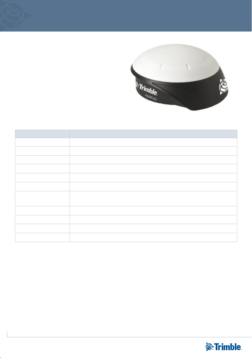
Trimble AgGPS 162 receiver
Quick reference card
The Trimble® AgGPS® 162 receiver is a highperformance GPS / SBAS (WAAS, EGNOS, and
MSAS) receiver and antenna in a single, rugged
housing that is used for agriculture applications.
The AgGPS 162 receiver features the Trimble
®
OnPath
pass-to-pass accuracies, even in the absence of
SBAS signals.
advance filter technology for improved
SPECIFICATIONS
Item Description
Size (W x D x H) 182 mm x 196 mm x 86 mm (7.16 in x 7.71 in x 3.38 in)
Weight 0.8 kg (1.76 lbs)
Operating temperature -30 °C through +70 °C (-22 °F through +158 °F)
Storage temperature -40 °C through +85 °C (-40 °F through +185 °F)
Seal Unit seals to 5 PSID
Humidity Fully functional when 100% condensing humidity
Casing Low-profile UV-resistant plastic.
Dust-proof, waterproof, shock resistance, with one connector.
Mounting 15/8 inch threaded mounting hole, three integrated magnets for mounting directly to steel surface
Power consumption <4 Watts (10 to 16 V DC)
DGPS accuracy Sub meter, ±8–12 inch pass-to-pass
Position fix update rate 1, 5 Hz
Cross track error accuracy over 15 minutes, 95% of the time, in the United States Midwest with at least five satellites, PDOP ≤6, SNR
≥40, Elevation Mask = 8, using WAAS differential corrections. WAAS is a free service that is available in the USA. Specifications are
subject to change without notice.
1
Page 2
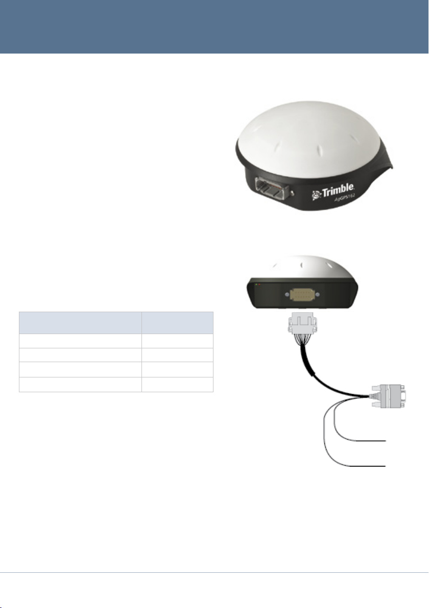
RECEIVER CONNECTIONS
This figure shows the Deutsch 12-pin receiver
connection.
There are three ports: two RS-232 serial ports
and one ISO 11783/J1939 (CAN 2.0B) port. The
connector can perform the following functions:
– accept power
– accept TSIP, RTCM, and ASCII inputs
– output RTCM, TSIP, and NMEA messages
– output 1 PPS signals
– output radar speed
CONNECTING TO AN EXTERNAL DEVICE
After installing the receiver and connecting the
appropriate cabling, you can connect the receiver to
various external devices.
Note: Do not bend the cable
at the Deutsch connector.
To connect the AgGPS 162
receiver to ...
an AgGPS Autopilot
a field computer 50166 / 68463
a yield monitor
AgGPS 162 breakout cable (radar) 68463
1
You must enable the AgGPS 162 receiver for use with the Autopilot
system. An upgrade passcode is required.
2
To connect directly to the yield monitor, you may need an additional
model-specific cable. See your yield monitor’s user guide.
3
This cable has not yet been released.
2
™
system
1
use cable P/N ...
50165
3
50166 / 68463
3
3
System level cable
(P/N 50166)
2
Deutsch 12-pin connector
DB-9 connector
Ground -ve
Power +ve
Page 3

Pin Function
1 CAN A High I/O
2 Port 1 RS-232 Tx OUT
3 Port 1 RS-232 Rx IN
4 PPS OUT
5 Signal GND
6 Port 1 RTS OUT
7 Radar OUT/ Event OUT
8 Port 1 CTS IN
9 Event IN
10 V+ IN / OUT
11 V– IN / OUT
12 CAN A Low I/O
Power LED
LED color LED flash State
Off Off Off
Blue Solid On
PIN OUT DIAGRAMS
LED INDICATORS
Status LED
LED color LED flash State
Off Off Off
Yellow Fast Not locked on or tracking enough
satellites for fix.
Yellow Slow Computing autonomous but no DGPS
fix.
Yellow Solid Computing autonomous GPS positions
(2 or 3D).
Blue Fast Computing DGPS positions, but no
DGPS signal and approaching DGPS
age limit.
Blue Slow Computing DGPS position, but no DGPS
signal (using on old corrections).
Blue Solid Normal operation, computing DGPS
solution.
Status LED Power LED
3
Page 4

MOUNTING THE RECEIVER
Use the following guidelines when choosing a
location for mounting the receiver:
– Choose a flat surface on the vehicle’s centerline.
– Mount the receiver on the highest part of the
vehicle, in an area with a clear view of the sky.
– Allow clearance for machine storage entrances.
– Mount the receiver above metal surfaces. If you
are mounting the receiver on a non-metal cab,
use the metal mounting plate.
– Do not mount the receiver close to electrical
cables, metal masts, air conditioning units
(machine cab blower fans), or machine accessory
lights.
– Mount the receiver at least one meter (about
three feet) from transmitting antennas
(for example, cell phone or FM two-way
radio antennas), radar arrays, or satellite
communication equipment.
– Avoid areas with high vibration, excessive heat,
electrical interference, and strong magnetic fields
such as those generated by alternators.
Receiver
Centerline
Top view
DEFAULT SETTINGS
Setting Value Setting Value
Elevation mask 8° PDOP mask 30
SNR mask 35 db/Hz Position rate 5 Hz
Position filter BF Enable (This sets the OnPath filter to ON) NMEA output messages 9600
4
Page 5

CONFIGURING THE RECEIVER
Use the Trimble AgRemote software to configure GPS, SBAS, or port settings in the AgGPS 162 receiver.
To connect to the receiver using AgRemote:
1. Install AgRemote on a computer that is running the Windows® 95, 98, Me, NT, 2000, or Windows XP
operating system.
2. Use the optional data/power cable (requires RS-232) to connect the receiver to a serial port on the
computer.
Note - If the computer has only USB ports, use a USB-to-serial converter cable to connect the data/power cable
to a USB port.
3. Connect the receiver to a power source.
4. Click Start / Programs / AgRemote to run the AgRemote software.
5. From the File menu, select Connect. The Port Settings dialog appears.
6. Specify connection settings. By default, AgRemote uses the settings shown below.
5
Page 6

AgGPS 162 receiver
7. Click OK. AgRemote connects to the receiver. The main AgRemote display shows status information
for the receiver:
The following screen shows GPS tracking and WAAS satellite information:
Resetting the receiver to factory defaults
You can use the AgRemote software to reset the AgGPS 162 receiver to its factory default settings.
1. Use the AgRemote software to connect to the receiver.
2. From the File menu, select Clear BB Ram.
A message appears, asking you to confirm that you want to reset the receiver.
3. Click Yes.
Factory defaults are now applied to the receiver.
TRIMBLE AGRICULTURE DIVISION
10355 Westmoor Drive
Suite #100
Westminster, CO 80021
USA
800-865-7438 Phone (US Toll Free)
+1-913-495-2700 Phone
+1-913-495-2750 Fax
www.trimble.com
*67746-00-ENG*
67746-00-ENG
© 2009. Trimble Navigation Limited. All rights reserved. Trimble, the Globe
and Triangle logo, AgGPS, and OnPath are trademarks of Trimble Navigation
Limited, registered in the United States and in other countries. Autopilot
is a trademarks of Trimble Navigation Limited. Microsoft and Windows are
registered trademarks of Microsoft Corporation in the United States and/or
other countries. Version 1.00, Rev A (February 2009).
6
 Loading...