

Page 1
Programmable Multiband Amplier
TMB 10A, TMB 10B, TMB 10C, TMB 10S
Model Item no.
TMB 10A, TMB 10B, TMB 10C, TMB 10S
324575/76/77/78
Version EN
triax.com
Page 2

Header (gælder alle engelske sider):
TMB Programmable Multiband amplifier
TMB 10A – TMB 10B – TMB 10C – TMB 10S
TMB Programmable Multiband Amplier
G
G
G
e
e
e
n
n
n
e
e
e
r
r
r
a
a
a
l
l
l
i
i
i
n
n
n
f
f
f
o
o
o
r
r
r
m
m
m
a
a
a
t
t
t
i
i
i
o
o
o
n
n
n
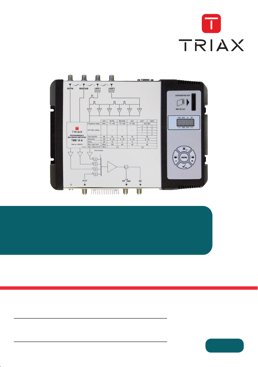
The processing units in the TMB10 range are used to selectively filter analogue and digital UHF
channels. These units also couple and amplify VHF programmes according to the satellite band model
(IF).
TMB10 units have one amplified wide band coupling input; 10 UHF filters, distributed over 3 inputs
with programmable bandwidth from 1 to 7 channels (8 to 56 MHz), making it suitable for most
situations.
An individual setting for each filter or frequency band, and automatic control of the UHF output level,
for aligning service plan levels.
TMB-10A – Ref.: 324575
5 inputs:
BI - FM, BIII - DAB, AUX, UHF1, UHF2
UHF Gain = 55 dB
BI - BIII Gain = 48 dB
AUX Gain = 39 dB
UHF output level = 124 dBµV (DIN 45004B)
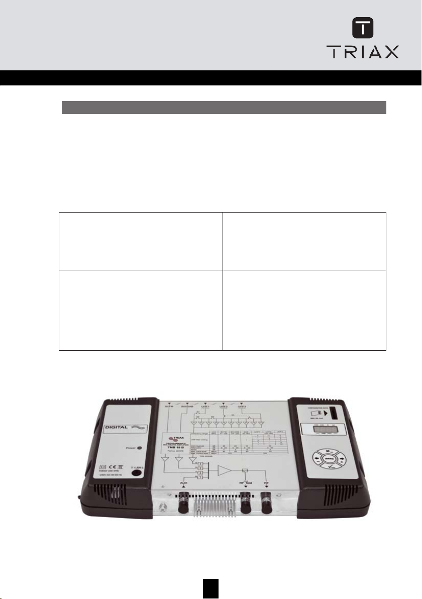
TMB-10B – Ref.: 324576
6 inputs:
BI - FM, BIII - DAB, AUX, UHF1, UHF2, UHF3
UHF Gain = 55 dB
BI - BIII Gain = 48 dB
AUX Gain = 39 dB
UHF output level = 124 dBµV (DIN 45004B)
TMB-10C – Ref.: 324578
6 inputs:
BI - FM, BIII - DAB, AUX, UHF1, UHF2, UHF3
UHF Gain = 45 dB
BI - BIII Gain = 45 dB
AUX Gain = 40 dB
UHF output level = 124 dBµV (DIN 45004B)
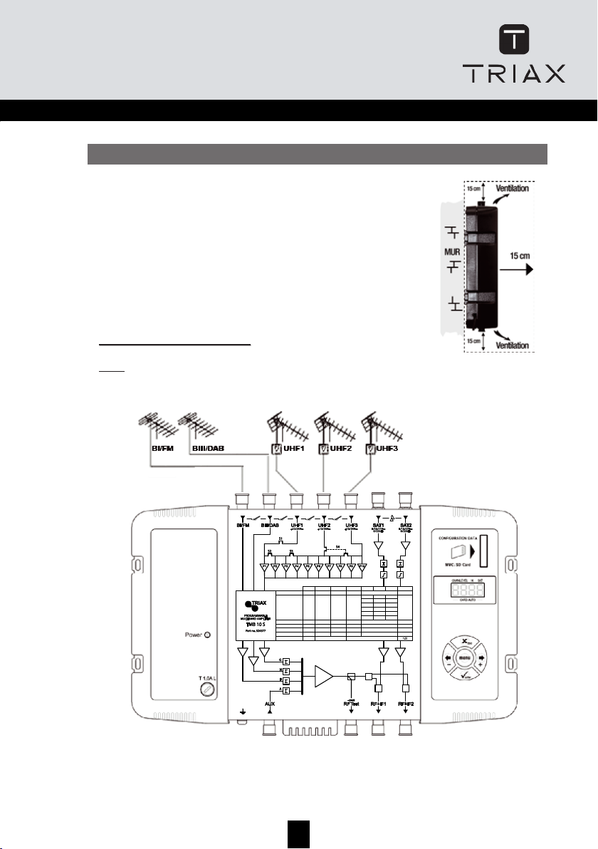
TMB-10S – Ref.: 324577
8 inputs:
BI - FM, BIII - DAB, AUX, UHF1, UHF2, UHF3, 2
x SAT
SAT Gain = 40 dB
UHF Gain = 48 dB
BI - BIII Gain = 43 dB
AUX Gain = 33 dB
UHF output level = 120 dBµV (DIN 45004B)
SAT output level = 120 dBµV (EN 50083-3)
GB
3
TMB 10A • TMB 10B • TMB 10C • TMB 10S
GB
General information .............................................................................................................................. 2
Safety Instructions ................................................................................................................................3
Installing the unit................................................................................................................................... 4
CCoonnnneeccttiinngg tthhee uunniit
Programming the unit ........................................................................................................................... 5
Menus ..................................................................................................................................................... 6
Diagrams .............................................................................................................................................. 19
Technical Specifications..................................................................................................................... 23
Notes..................................................................................................................................................... 25
FFaaccttoorryy rreesseet
DDaattee ooff mmaannuuffaaccttuurre
CCoonnffiigguurriinngg tthhee uunniit
O
p
e
r
a
t
i
n
O
p
e
r
a
t
i
n
O
p
e
r
a
t
i
CHAN.......................................................................................................................................... 6
LEVEL ........................................................................................................................................ 6
C
H
A
N
M
C
H
A
N
M
C
H
A
N
M
D
i
s
t
r
i
b
u
t
D
i
s
t
r
i
b
u
D
i
s
t
r
i
b
u
U
H
F
f
i
l
t
e
U
H
F
f
i
l
t
e
U
H
F
f
i
l
t
F
i
n
e
t
u
n
F
i
n
e
t
u
n
F
i
n
e
t
u
n
C
o
n
f
i
g
u
r
C
o
n
f
i
g
u
C
o
n
f
i
g
u
A
u
t
o
m
a
t
A
u
t
o
m
a
A
u
t
o
m
a
C
A
R
D
M
C
A
R
D
M
C
A
R
D
M
S
A
T
M
e
S
A
T
M
e
S
A
T
M
e
t ............................................................................................................................. 4
t ....................................................................................................................................... 5
g
p
r
i
n
c
i
p
g
p
r
i
n
c
i
p
n
g
p
r
i
n
c
i
p
e
n
u
e
n
u
e
n
u
.................................................................................................................................... 7
i
o
n
o
f
U
H
t
i
o
n
o
f
U
H
t
i
o
n
o
f
U
H
r
w
i
d
t
h
(
r
w
i
d
t
h
(
e
r
w
i
d
t
h
(
i
n
g
i
n
g
i
n
g
.................................................................................................................................... 10
i
n
g
t
h
e
a
r
i
n
g
t
h
e
a
r
i
n
g
t
h
e
a
i
c
U
H
F
g
t
i
c
U
H
F
g
t
i
c
U
H
F
g
e
n
u
e
n
u
e
n
u
.................................................................................................................................. 13
n
u
n
u
n
u
..................................................................................................................................... 18
e............................................................................................................................ 5
t ............................................................................................................................. 6
l
e
l
e
l
e
.......................................................................................................................... 6
F
f
i
l
t
e
r
s
F
f
i
l
t
e
r
s
F
f
i
l
t
e
r
s
C
................................................................................................................ 7
H
A
N
m
e
n
u
C
H
A
C
H
A
t
t
e
n
t
t
e
n
t
t
e
n
a
i
n
a
i
n
a
i
n
)
N
m
e
n
u
)
N
m
e
n
u
)
........................................................................................................ 9
u
a
t
o
r
s
(
L
E
V
E
L
m
e
n
u
u
a
t
o
r
s
(
L
E
V
u
a
t
c
o
n
c
o
n
c
o
n
E
o
r
s
(
L
E
V
t
r
o
l
A
u
t
o
t
r
o
l
A
u
t
o
t
r
o
l
A
u
t
o
)
L
m
e
n
u
E
m
)
L
m
e
n
u
)
.................................................................................. 11
e
n
u
m
e
n
u
m
e
n
u
....................................................................................... 12
2
Page 3
G
G
G
e
e
e
n
n
n
e
e
e
r
r
r
a
a
a
l
l
l
i
i
i
n
n
n
f
f
f
o
o
o
r
r
r
m
m
m
a
a
a
t
t
t
i
i
i
o
o
o
n
n
n
GB
The processing units in the TMB10 range are used to selectively filter analogue and digital UHF
channels. These units also couple and amplify VHF programmes according to the satellite band model
(IF).
TMB10 units have one amplified wide band coupling input; 10 UHF filters, distributed over 3 inputs
with programmable bandwidth from 1 to 7 channels (8 to 56 MHz), making it suitable for most
situations.
An individual setting for each filter or frequency band, and automatic control of the UHF output level,
for aligning service plan levels.
TMB-10A – Ref.: 324575
BI - FM, BIII - DAB, AUX, UHF1, UHF2
5 inputs:
UHF Gain = 55 dB
BI - BIII Gain = 48 dB
AUX Gain = 39 dB
UHF output level = 124 dBµV (DIN 45004B)
TMB-10C – Ref.: 324578
BI - FM, BIII - DAB, AUX, UHF1, UHF2, UHF3
6 inputs:
UHF Gain = 45 dB
BI - BIII Gain = 45 dB
AUX Gain = 40 dB
UHF output level = 124 dBµV (DIN 45004B)
TMB-10B – Ref.: 324576
BI - FM, BIII - DAB, AUX, UHF1, UHF2, UHF3
6 inputs:
UHF Gain = 55 dB
BI - BIII Gain = 48 dB
AUX Gain = 39 dB
UHF output level = 124 dBµV (DIN 45004B)
TMB-10S – Ref.: 324577
BI - FM, BIII - DAB, AUX, UHF1, UHF2, UHF3, 2
8 inputs:
x SAT
SAT Gain = 40 dB
UHF Gain = 48 dB
BI - BIII Gain = 43 dB
AUX Gain = 33 dB
UHF output level = 120 dBµV (DIN 45004B)
SAT output level = 120 dBµV (EN 50083-3)
3
Page 4

S
S
S
a
a
a
f
f
f
e
e
e
t
t
t
y
y
y
I
I
I
n
n
n
s
s
s
t
t
t
r
r
r
u
u
u
c
c
c
t
t
t
i
i
i
o
o
o
n
n
n
s
s
s
TMB Programmable Multiband Amplier
I
I
I
n
n
n
s
s
s
t
t
t
a
a
a
l
l
l
l
l
l
i
i
i
n
n
n
g
g
g
t
t
t
h
h
h
e
e
e
u
u
u
n
n
n
i
i
i
t
t
t
We recommend you install the unit in a sufficiently ventilated place.
Natural ventilation must be able to occur through the ventilation grids;
leave a minimum space of 15 cm around the unit to ensure maximum
ventilation.
When installing or cabling the unit, we recommend you disconnect the
mains power cable.
CCoonnnneeccttiinngg tthhee uunniitt
Note:
UHF inputs are remotely supplied and protected against short circuits. The power available is
12 or 24V, 50mA max. The preamplifier is detected automatically; only the remote power voltage
can be programmed.
Max. Output level*
Max. Input level
Noise
Attenuator
Gain (typical)
UHF lter setting
Frequency range MHz
Unit
dBµV
dBµV
dB
dB
dB
47÷108
BI-FM
116
80
5
0…20
43
/
174÷230
BIII-DAB
80
5
0…20
43
/
47÷862
AUX
80
10
0…20
33
/
UHF1
120
–
1
3
–
1
3
470÷862
UHF2
80
9
0…20
48
–
–
–
8
7
5
UHF3
10
9
7
2
2
2
950÷2150
SAT
79
6
0…20
40
/
*DIN 45004B
GB
5
TMB 10A • TMB 10B • TMB 10C • TMB 10S
GB
Important: The unit should only be opened by a qualified technician.
• Disconnect the unit before carrying out any work on it, as some powered components are
dangerous (risk of electrical shock).
• To maintain the temperature of the unit within its normal operating range, ensure the free
circulation of air around the unit (avoid placing it in enclosed spaces). The ventilation grids must
be free of any obstruction.
• Ensure that no liquids can penetrate inside the unit (splashes and/or run off).
• Do not install the unit in a damp place. If there are traces of condensation on the unit, do not use it
until it has dried completely.
• The mains power cable and the HF connection cables must be in good condition and free to move
(neither crushed nor obstructed).
• The mains plug, easily accessible for the technician, must be out of reach of children.
Earthing the unit
• Your aerial installation must comply with the requirements specified by the European provisions
EN 50083 (conformity of collective installations) and EN 60065 (standards in force for electrical
protection).
Replacing fuses
• Only a qualified technician can replace defective fuses.
Electromagnetic compatibility (EMC)
• Ensure that the screws on the box are properly tightened.
• Cables and connection terminals should show no signs of rust.
4
Page 5
I
n
s
t
a
l
l
i
n
g
t
h
e
u
n
i
t
I
n
s
t
a
l
l
i
n
g
t
h
I
n
s
t
a
l
l
i
We recommend you install the unit in a sufficiently ventilated place.
Natural ventilation must be able to occur through the ventilation grids;
leave a minimum space of 15 cm around the unit to ensure maximum
ventilation.
When installing or cabling the unit, we recommend you disconnect the
mains power cable.
n
e
g
t
h
e
u
n
i
t
u
n
i
t
GB
CCoonnnneeccttiinngg tthhee uunniitt
UHF inputs are remotely supplied and protected against short circuits. The power available is
Note:
12 or 24V, 50mA max. The preamplifier is detected automatically; only the remote power voltage
can be programmed.
Unit
BI-FM
BIII-DAB
AUX
UHF1
UHF2
UHF3
Frequency range MHz
UHF lter setting
Gain (typical)
Attenuator
Noise
Max. Input level
Max. Output level*
*DIN 45004B
47÷108
174÷230
47÷862
/
/
/
dB
43
43
dB
dB
dBµV
dBµV
33
0…20
0…20
0…20
5
5
10
80
80
80
116
SAT
470÷862
950÷2150
3
5
2
1
7
2
–
8
2
/
3
–
7
1
–
9
–
–
10
40
48
0…20
0…20
6
9
79
80
120
5
Page 6
P
P
P
r
r
r
o
o
o
g
g
g
r
r
r
a
a
a
m
m
m
m
m
m
i
i
i
n
n
n
g
g
g
t
t
h
h
e
e
u
u
n
n
i
i
t
t
g
g
TMB Programmable Multiband Amplier
CCoonnffiigguurriinngg tthhee uunniitt
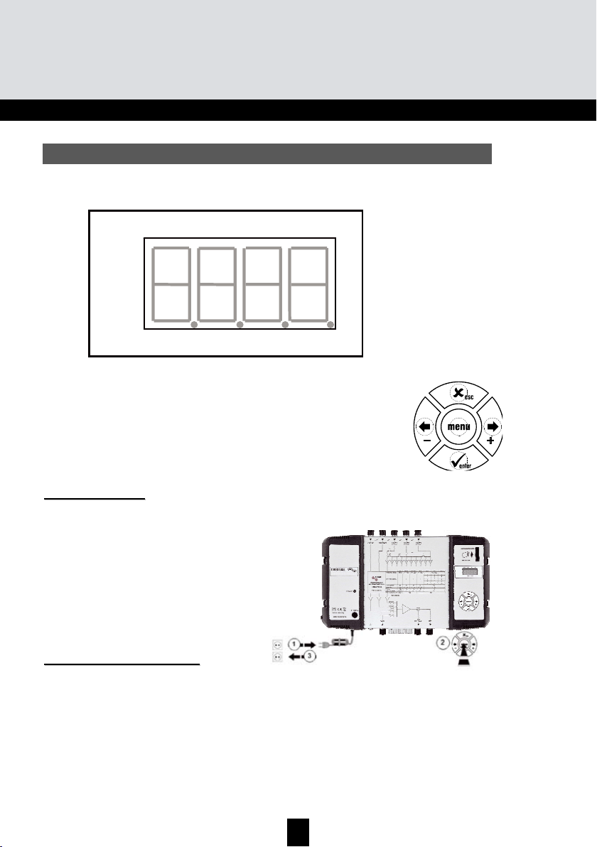
On powering on, the unit is in standby mode, a light segments flashes across the display:
O
O
O
p
p
p
e
e
e
r
r
r
a
a
a
t
t
t
i
i
i
n
n
n
g
g
g
p
p
p
r
r
r
i
i
i
n
n
n
c
c
c
i
i
i
p
p
p
l
l
l
e
e
e
To access the configuration menus, press the menu button until the light segment is under the
menu to open and press enter.
To summarize:
• To scroll through the menus, use the menu button.
• To enter a menu, press enter.
• To exit a menu, press the menu button.
Note:
If the button is not pressed for one minute, the unit switches to standby mode.
M
M
M
e
e
e
n
n
n
u
u
u
s
s
s
CHAN
Configuration of UHF filters:
• Channel
• Bandwidth (1 to 7 channels; 8 to 56 MHz)
LEVEL
Configuring of attenuators.
IN
Configuration of filter distribution on UHF1, 2 and 3 inputs.
Selection of remote power supply (12 or 24 V
DC
).
AUTO
Use of the AGC.
Automatic alignment of UHF programmes.
CARD
Reading and saving of configurations
Activation and configuration of the PIN code.
SAT
Configuring of IF attenuators.
9 dB equalization ON/OFF
Selection of remote power supply (0, 13 or 17 V
DC
).
Selection 22 kHz (ON/OFF).
GB
7
TMB 10A • TMB 10B • TMB 10C • TMB 10S
GB
A 4-digit display and a keypad are all you need to programme the unit. Follow the procedure below
for configuring the various parameters.
When the unit is powered on:
• the programme mode is in standby:
• by default, the system is configured as follows:
• all the UHF filters are deactivated (display "
• the attenuators are at zero.
FFaaccttoorryy rreesseett
If necessary, to revert to factory settings, follow the procedure below:
1. Disconnect the power cable
2. Press the
3. Connect the power cable
The unit erases all the programming parameters,
including the PIN code, and switches to standby mode.
• You can release the
the display shows “8888”
o UHF1 Î 3 UHF filters
o UHF2 Î 0 UHF filters
o UHF3 Î 7 UHF filters
esc button and hold it
t
h
e
u
n
i
t
CHAN LEVEL IN SAT
Digit 1 Digit 2
Di
it 3
esc button when
- -"),
it 4
Di
____ AUTO CARD ____
DDaattee ooff mmaannuuffaaccttuurree
If necessary, to consult the unit’s date of manufacture and version, press the button
seconds, the unit displays the date of manufacture in the format; A-SS with A being the last digit of
the year of manufacture, SS the week of manufacture.
- & +. For 2
6
Page 7

GB
CCoonnffiigguurriinngg tthhee uunniitt
On powering on, the unit is in standby mode, a light segments flashes across the display:
O
p
e
r
a
t
i
n
g
p
r
i
n
c
i
O
p
e
r
a
t
i
n
O
p
To access the configuration menus, press the menu button until the light segment is under the
menu to open and press enter.
To summarize:
Note:
If the button is not pressed for one minute, the unit switches to standby mode.
M
M
M
g
e
r
a
t
i
n
g
• To scroll through the menus, use the menu button.
• To enter a menu, press enter.
• To exit a menu, press the menu button.
e
n
u
s
e
n
u
s
e
n
u
s
p
p
r
i
n
c
i
p
p
r
i
n
c
i
p
l
e
l
e
l
e
CHAN
Configuration of UHF filters:
• Channel
• Bandwidth (1 to 7 channels; 8 to 56 MHz)
LEVEL
Configuring of attenuators.
IN
Configuration of filter distribution on UHF1, 2 and 3 inputs.
Selection of remote power supply (12 or 24 V
).
DC
AUTO
Use of the AGC.
Automatic alignment of UHF programmes.
CARD
Reading and saving of configurations
Activation and configuration of the PIN code.
SAT
Configuring of IF attenuators.
9 dB equalization ON/OFF
Selection of remote power supply (0, 13 or 17 V
Selection 22 kHz (ON/OFF).
).
DC
7
Page 8
TMB Programmable Multiband Amplier
Start
menu
'
'
+
0
-
0
or
'
Select the sub-menu
IN – input menu
U – Distribution of UHF filters on the
inputs UHF1, UHF2 and UHF3;
Po – Selection of the remote power
supply: 12V
DC
or 24VDC
'
X esc
'
+
0
-
0
or
Select the distribution of UHF filters
'
+
0
-
0
or
Remote power supply
'
X
esc
/
This menu is used to select the value of the remote
power supply on the inputs UHF 1, 2 and 3. The
unit automatically detects the amplifier connected
and switches the remote power supply to ON.
Distribution of UHF filters
352
172
082
307
109
001
Remove the mains cable before any
wiring work
GB
9
TMB 10A • TMB 10B • TMB 10C • TMB 10S
GB
M
u
e
n
u
M
e
n
u
M
e
n
u
Number of filters per
Number of filters per
t
i
o
n
o
u
t
i
o
n
o
u
t
i
o
n
o
Input UHF1 UHF2 UHF3
UHF input
Input UHF1 UHF2 UHF3
UHF input
f
U
H
f
U
H
f
U
H
F
f
i
l
t
e
r
F
s
f
i
l
t
e
r
s
F
f
i
l
t
e
r
s
423315-
-6-
352
172
-82
3-7
1-9
- - 10
C
H
A
N
C
H
A
N
C
H
A
N
TMB units have 6 or 10 configurable UHF filters. The UHF filters are distributed over the three
inputs UHF1, UHF2, UHF3 as shown below.
TMB 10A
TMB 10B, C & S
Each UHF filter can be configured for a bandwidth of 8 to 56 MHz (1 to 7 channels).
D
i
s
t
r
i
b
D
i
s
t
r
i
b
D
i
s
t
r
i
b
Go to the menu IN by placing the light segment under the IN mark and press enter.
• Press enter again to change the configuration of the UHF inputs (part of the display flashes)
• Press the buttons + or - to select the distribution of the filters over the UHF inputs.
Notes:
Each UHF filter can be deactivated. Just configure the filter in question to the value – in the "CHAN"
menu.
8
Page 9

X
GB
IN – input menu
Start
menu
'
U – Distribution of UHF filters on the
inputs UHF1, UHF2 and UHF3;
Po – Selection of the remote power
supply: 12V
or 24VDC
DC
Distribution of UHF filters
352
172
082
307
109
001
X esc
'
'
'
'
Select the sub-menu
or
0
-
Select the distribution of UHF filters
0
-
'
0
+
or
0
+
This menu is used to select the value of the remote
power supply on the inputs UHF 1, 2 and 3. The
unit automatically detects the amplifier connected
and switches the remote power supply to ON.
Remove the mains cable before any
wiring work
Remote power supply
0
-
or
0
+
'
esc
/
9
Page 10

TMB Programmable Multiband Amplier
F
F
F
i
i
i
n
n
n
e
e
e
t
t
t
u
u
u
n
n
n
i
i
i
n
n
n
g
g
g
This function is used to offset the frequency of the filter concerned, to adjust the filters according to
the characteristics of the signals received (offset, adjacent channels, etc.).
Check the offset on your measurement apparatus.
Start
'
X
esc
'
0
0
The function only acts
on the filter selected
Select the filter using the
keys + and –
'
'
X esc
'
X esc
'
GB
11
TMB 10A • TMB 10B • TMB 10C • TMB 10S
GB
U
H
F
f
i
U
H
F
f
U
H
F
f
CHAN – menu
X esc
/
X esc
/
X esc
/
X esc
/
l
t
e
r
w
i
d
t
h
(
C
H
A
N
m
e
n
u
)
i
l
t
e
r
w
i
d
t
h
(
C
H
A
N
i
l
t
e
r
w
i
d
t
h
(
Start
menu
C
H
A
N
'
'
m
m
e
e
n
u
)
n
u
)
Filter number 1 to 10
(0 for filter no. 10)
Select the filter to configure
0
-
'
Choose the start channel
0
-
Choose the end channel
0
+
'
'
'
'
X esc
'
1 channel max. 7 channels
-
/
21
10
or
or
21
C – Channel menu
0
+
0
+
27
Filter start channel.
If the filter is not used, the
display shows “--“.
The display dot flashes when the
filter has a width > 1 channel.
Page 11

X
GB
F
i
n
e
t
u
n
i
n
g
F
i
n
e
F
i
n
e
This function is used to offset the frequency of the filter concerned, to adjust the filters according to
the characteristics of the signals received (offset, adjacent channels, etc.).
t
u
n
i
n
g
t
u
n
i
n
g
The function only acts
on the filter selected
'
X esc
'
Check the offset on your measurement apparatus.
0
Start
esc
'
Select the filter using the
keys + and –
'
0
X esc
'
'
11
Page 12

X
TMB Programmable Multiband Amplier
A
A
A
u
u
u
t
t
t
o
o
o
m
m
m
a
a
a
t
t
t
i
i
i
c
c
c
U
U
U
H
H
H
F
F
F
g
g
g
a
a
a
i
i
i
n
n
n
c
c
c
o
o
o
n
n
n
t
t
t
r
r
r
o
o
o
l
l
l
A
A
A
u
u
u
t
t
t
o
o
o
m
m
m
e
e
e
n
n
n
u
u
u
Note: Setting of the levels BI-II / BIII / AUX is not automatic.
Start
menu
'
'
'
AUTO – menu
√ enter
'
+
0
-
0
or
√ enter
'
Display the value of the output level
X
esc
'
X esc
'
min. max.
+
0
-
0
or
Select the sub-menu
'
'
+
0
-
0
or
'
X esc
'
X esc
'
IMPORTANT!
The unit memorizes the average output level. A
variation of ± 1 dB triggers the function and
compensates the variation within gain and
attenuation limits
AGC mode hides all other menus. To modify the
parameters, switch the AGC mode to OFF.
GB
13
TMB 10A • TMB 10B • TMB 10C • TMB 10S
GB
Setting the levels.
There are three types of level setting:
• “Manual” setting of output levels (LEVEL menu)
• automatic alignment of UHF filter output levels to a value entered by the user. (Auto menu,
sub-menu LEU)
• automatic UHF gain control (Auto menu, sub-menu AGC)
C
C
C
Go to the LEVEL menu by placing the light segment under the LEVEL mark and press enter.
L – level menu
o
n
f
i
g
u
r
i
n
o
n
f
o
n
• Press the buttons + or - to select the channel to configure.
•
• When the display flashes, you can configure the attenuation (20 indicates attenuation 0; 1
• Confirm by pressing enter
g
i
g
u
r
i
n
f
g
i
g
u
r
i
n
g
Confirm by pressing enter
indicates max attenuation)
t
h
e
a
t
t
t
h
e
a
t
t
t
h
e
a
t
Start
menu
e
n
u
e
n
u
t
e
n
u
'
a
t
o
r
a
t
o
r
a
t
o
r
'
s
(
L
s
(
L
s
(
L
1…0 – filter number, from 1 to 10
H – VHF band (BIII)
F – FM band (BI/FM)
A – auxiliary input (AUX)
G – UHF Gain
m
E
V
E
L
L
m
E
V
E
m
E
V
E
L
e
n
u
)
e
n
u
)
e
n
u
)
Select sub-menu
or
0
-
L – for LEVEL menu
Attenuation -1 to -20 dB
0
+
'
'
esc
Choose the attenuation
or
0
-
0
+
'
12
Page 13

X
GB
A
u
t
o
m
a
t
i
c
U
H
F
g
a
i
n
c
o
n
t
r
o
l
A
u
t
o
m
a
t
i
c
U
H
F
g
a
i
n
A
u
t
o
m
a
t
i
c
U
Note: Setting of the levels BI-II / BIII / AUX is not automatic.
H
F
g
Start
menu
a
i
n
'
c
c
A
o
n
t
r
o
l
A
o
n
t
r
o
l
A
AUTO – menu
'
X esc
'
u
t
o
m
u
t
o
m
u
t
o
m
Select the sub-menu
0
-
n
u
e
e
n
u
n
u
e
or
0
+
'
Display the value of the output level
√ enter
√ enter
'
'
min. max.
0
or
-
+
0
X esc
'
esc
'
'
'
IMPORTANT!
The unit memorizes the average output level. A
variation of ± 1 dB triggers the function and
compensates the variation within gain and
attenuation limits
AGC mode hides all other menus. To modify the
parameters, switch the AGC mode to OFF.
or
0
-
+
0
'
X esc
'
13
Page 14

TMB Programmable Multiband Amplier
CARD Menu
Start
Continued on next page
APL firmware update
EHP data memorization
InP read configuration files
PIN activation and configuration of the PIN code
The SD/MMC card must be formatted in FAT 16.
The files should be placed in the root directory.
If the SD/MMC card has no configuration file the
display will show noFL during reboot.
Select the sub-menu
GB
15
TMB 10A • TMB 10B • TMB 10C • TMB 10S
GB
C
A
C
A
C
A
TMB units have an SD/MMC interface to save or read configurations and for updating the product.
This menu includes 4 sub-menus:
When the card contains the update file (tm_tmb10.tlp), and the enter key is pressed; the update
occurs automatically and the display shows "boot" during the whole operation.
Select the sub-menu and choose a filename. The display flashes when the file already exists. By
pressing the enter key, it is “overwritten".
Select the sub-menu and display the name of the file to read. When the key is pressed, reading
starts; the display shows "Good" when the procedure is complete.
When this function is active, the PIN code is requested to access the menus (display your PIN code
using the keypad and confirm by pressing enter). If no key is pressed for 30 seconds, the unit
switches to standby mode and the PIN code must be entered again to access the menus.
Important.
R
D
M
e
n
u
R
D
R
D
• APL updating of the firmware
• EHP data memorization
• InP read the configuration files
• PIN activation and configuration of the PIN code
• When no SD card is inserted in the unit, the display indicates Err when one of the menus
APL, EHP or InP is used.
• The SD/MMC card must be formatted in FAT16. The files should be placed in the root
directory.
• The configuration files are names specifically according to the model number (S00x for
TMB10S, C00x for TMB10C, B00x for TMB10B, A00x for TMB10A).
• The default PIN code is 2312.
M
e
n
u
M
e
n
u
14
Page 15

GB
CARD Menu
Start
APL firmware update
EHP data memorization
InP read configuration files
PIN activation and configuration of the PIN code
Select the sub-menu
The SD/MMC card must be formatted in FAT 16.
The files should be placed in the root directory.
If the SD/MMC card has no configuration file the
display will show noFL during reboot.
Continued on next page
15
Page 16

TMB Programmable Multiband Amplier
EHP Export Menu
Start
Insert the SD car d
The dot flashes when the
process begi ns
When the displa y flashes, the file has
been created o n the SD car d.
Press “enter”, t o confirm and o verwrite
the existing file .
Select the file to r ead
GB
17
TMB 10A • TMB 10B • TMB 10C • TMB 10S
GB
Continued from the previous page
16
Page 17

GB
EHP Export Menu
Start
The dot flashes when the
process begi ns
Select the file to r ead
Insert the SD car d
When the displa y flashes, the file has
been created o n the SD car d.
Press “enter”, t o confirm and o verwrite
the existing file .
17
Page 18

TMB Programmable Multiband Amplier
S
S
S
A
A
A
T
T
T
M
M
M
e
e
e
n
n
n
u
u
u
• TMB 10S models have two IF amplification channels. The Sat menu is used to configure the
remote power supply of the LNB (OFF / 13 /17 V
DC
), to activate the 22kHz generator and
the 9dB equalizer.
Start
menu
'
'
+
0
-
0
or
'
Select the channel to configure
SAT – menu
+
0
-
0
or
√ enter
'
+
0
-
0
or
Select the sub-menu
√ enter
'
Display the value
X esc
'
X esc
'
X esc
'
IL – adjust the output level
Po – LNB supply: 0, 13 or 17V
DC
to – 22kHz generator on / off
E – equalizer on / off,
GB
19
TMB 10A • TMB 10B • TMB 10C • TMB 10S
GB
InP Import
Menu
Start
Insert the SD card
The dot flashes when the
process begins
Select the file t o read
18
Page 19

GB
S
A
T
M
e
n
u
S
A
T
S
A
T
• TMB 10S models have two IF amplification channels. The Sat menu is used to configure the
M
e
n
u
M
e
n
u
remote power supply of the LNB (OFF / 13 /17 V
the 9dB equalizer.
Start
menu
SAT – menu
'
), to activate the 22kHz generator and
DC
IL – adjust the output level
Po – LNB supply: 0, 13 or 17V
to – 22kHz generator on / off
E – equalizer on / off,
DC
X esc
'
X esc
'
√ enter
√ enter
'
'
'
'
Select the channel to configure
or
0
-
Select the sub-menu
0
-
0
-
0
+
or
+
Display the value
or
+
0
0
X esc
'
19
Page 20

TMB Programmable Multiband Amplier
Diagram TMB-10B
Max. Output level*
Max. Input level
Noise
Attenuator
Gain (typical)
UHF filter setting
Frequency range MHz
Unit
dBµV
dBµV
dB
dB
dB
47÷108
BI-FM
122
80
5
0…20
48
/
174÷230
BIII-DAB
80
5
0…20
48
/
47÷862
AUX
80
10
0…20
39
/
UHF1
124
–
1
3
–
1
3
470÷862
UHF2
80
9
0…20
55
–
–
–
8
7
5
UHF3
10
9
7
2
2
2
*DIN 45004B
GB
21
TMB 10A • TMB 10B • TMB 10C • TMB 10S
GB
D
i
a
D
i
a
D
i
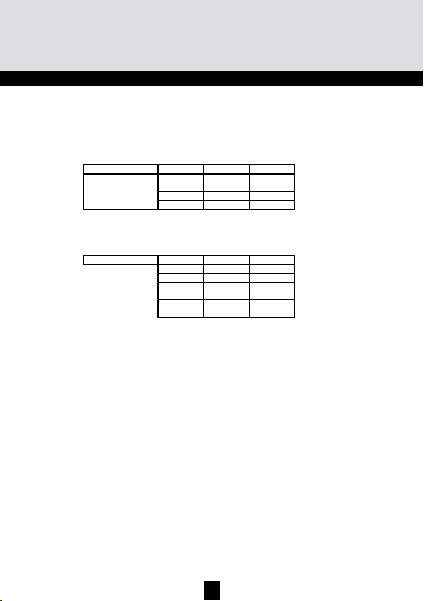
Diagram TMB-10A
g
r
a
m
s
r
a
m
r
a
m
s
s
Frequency range MHz
UHF filter setting
Gain (typical)
Attenuator
Noise
Max. Input level
Max. Output level*
*DIN 45004B
dBµV
dBµV
Unit
dB
dB
dB
UHF1
BI-FM
BIII-DAB
47÷108
174÷230
/
48
0…20
5
80
122
0…20
AUX
47÷862
/
/
48
39
0…20
5
10
80
80
UHF2
470÷862
4
2
3
3
1
5
–6
55
0…20
9
80
124
g
a
g
20
Page 21

GB
Diagram TMB-10B
UHF1
UHF2
124
470÷862
5
7
8
–
–
–
55
0…20
9
80
UHF3
2
2
2
7
9
10
Frequency range MHz
UHF filter setting
Gain (typical)
Attenuator
Noise
Max. Input level
Max. Output level*
*DIN 45004B
dBµV
dBµV
Unit
47÷108
/
48
dB
0…20
dB
5
dB
80
122
174÷230
/
48
0…20
5
80
47÷862
39
0…20
10
80
3
1
–
/
3
1
–
AUX
BIII-DAB
BI-FM
21
Page 22

TMB Programmable Multiband Amplier
Diagram TMB-10S
Max. Output level*
Max. Input level
Noise
Attenuator
Gain (typical)
UHF filter setting
Frequency range MHz
Unit
dBµV
dBµV
dB
dB
dB
47÷108
BI-FM
116
80
5
0…20
43
/
174÷230
BIII-DAB
80
5
0…20
43
/
47÷862
AUX
80
10
0…20
33
/
UHF1
120
–
1
3
–
1
3
470÷862
UHF2
80
9
0…20
48
–
–
–
8
7
5
UHF3
10
9
7
2
2
2
950÷2150
SAT
79
6
0…20
40
/
*DIN 45004B
GB
23
TMB 10A • TMB 10B • TMB 10C • TMB 10S
GB
Diagram TMB-10C
*DIN45004B
22
Page 23

GB
Diagram TMB-10S
Unit
BI-FM
BIII-DAB
AUX
UHF1
UHF2
UHF3
Frequency range MHz
UHF filter setting
Gain (typical)
Attenuator
Noise
Max. Input level
Max. Output level*
*DIN 45004B
dBµV
dBµV
47÷108
174÷230
47÷862
/
/
dB
43
43
dB
0…20
dB
5
80
116
0…20
80
33
0…20
5
10
80
470÷862
3
5
1
7
–
/
8
3
–
1
–
–
–
48
0…20
9
80
120
SAT
950÷2150
2
2
2
/
7
9
10
40
0…20
6
79
23
Page 24

TMB Programmable Multiband Amplier
TMB 10A • TMB 10B • TMB 10C • TMB 10S
GB
T
e
c
h
n
i
c
a
l
S
p
e
c
i
f
i
c
a
t
i
o
n
s
T
e
c
h
n
i
T
e
AMPLIFICATION
Global UHF output attenuator
UHF output adjustment by AGC
Max. Output level VHF / UHF/
FILTERING
selectivity of filters at +/- 16MHz
POWER SUPPLY
Power consumption at 230VAC
MECHANICS
c
c
h
n
i
c
Reference / part number
Max. VHF/UHF input level
BIII/DAB input gain
Preacc. VHF/UHF input
UHF 1/2/3 inputs gain
SAT 1 and SAT 2 input gain
Preacc. SAT inputs
BIII / UHF / SAT Noise factor
Attenuator per input
SAT (DIN45004B)
Distribution of filters
Width of filtering channels
Adaptation of inputs
Adaptation of outputs
Remote supply UHF1,2 or 3
SAT inputs equipped
Operating temperature
Input/output connectors
Dimensions (H x W x D)
a
l
S
p
e
c
i
f
i
c
a
l
S
p
e
Name TMB-10A TMB-10B
Number of inputs
BI/FM input gain
AUX input gain
Test output
Voltage
Equipped inputs
LNB supply
22kHz generator
Test output
a
c
i
f
i
c
a
Units
5 6
dB 80/80
dB 48 45
dB 48 45
dB 39 40
dB 5
dB 55 / 55 /- 55 / 55 / 55
dB
dB
dB 5 / 9 / -
dB 0 to 20
dB 0 to 20
dB -9 to +10
dBµV 122 / 124 / -
dB -20
MHz 8 to 56
dB 16
dB >10
dB >10
VAC 230
VA 35
VDC/mA 12 or 24 /55
UHF 1 and 2 UHF 1, 2 and 3
VDC/mA
dB -20
ºC -5 to +50
"F" female
mm 225 x 360 x 50
t
i
o
n
s
t
i
o
n
s
324575 324576
See page 8 of this
manual
TMB-10C
324578
6
45 / 45 / 45
TMB-10S
324577
8
43
43
33
48 / 48 / 48
40
9 (switchable)
5 / 9 / 6
116 / 120 / 120
0,13 or 17 /300
ON / OFF
SAT 1 and 2
Filter data.
24
Page 25

47
to
240
Levels
GB
input output Test
MH z
MH z
MH z
MH z
Filter wid th
7, 9 or 10 filters
UHF3 2,
UHF2
5, 7 or 8 filters
UHF1
1 or 3 filters
& 470 to 862 MH z
(1 to 7 channels) 8 to 56
(1 to 7 channels) 8 to 56
(1 to 7 channels) 8 to 56
(1 to 7 channels) 8 to 56
(1 to 7 channels) 8 to 56
BI - B II 47 to 108 MHz
BIII 174 to 240 MHz
VHF-UHF
Filt er 1
Filt er 2
Filt er 3
Filt er 4
MH z
MH z
MH z
MH z
MH z
MH z
(1 to 7 channels) 8 to 56
(1 to 7 channels) 8 to 56
(1 to 7 channels) 8 to 56
(1 to 7 channels) 8 to 56
(1 to 7 channels) 8 to 56
Filt er 5
Filt er 6
Filt er 7
Filt er 8
Filt er 9
Filter 10
triax.com/support
Copyright © 2016 TRIAX. All rights reserved. The TRIAX Logo and TRIAX, TRIAX Multimedia
are registered trademarks or trademarks of the TRIAX Company or its afliates.
All specications in this guide are subject to change without further notice.
TRIAX A/S | Bjørnkærvej 3 | DK-8783 Hornsyld | Denmark
 Loading...