

Page 1
GB
Programmable Multiband Amplier
TMB 10A Ref.: 324575
TMB 10B Ref.: 324576
TMB 10S Ref.: 324577
GB | FR | ESP | SE | FI
Mounting instruction
TRIAX - your ultimate connection
1
Page 2

2
TMB Programmable Multiband Amplier
TMB 10A • TMB 10B • TMB 10S
GB
General information .............................................................................................................................. 2
Safety Instructions ................................................................................................................................3
Installing the unit................................................................................................................................... 4
CCoonnnneeccttiinngg tthhee uunniit
t ............................................................................................................................. 4
Programming the unit ........................................................................................................................... 5
FFaaccttoorryy rreesseet
t ....................................................................................................................................... 5
DDaattee ooff mmaannuuffaaccttuurre
e............................................................................................................................ 5
CCoonnffiigguurriinngg tthhee uunniit
t ............................................................................................................................. 6
O
O
O
p
p
p
e
e
e
r
r
r
a
a
a
t
t
t
i
i
i
n
n
n
g
g
g
p
p
p
r
r
r
i
i
i
n
n
n
c
c
c
i
i
i
p
p
p
l
l
l
e
e
e
.......................................................................................................................... 6
Menus ..................................................................................................................................................... 6
CHAN.......................................................................................................................................... 6
LEVEL ........................................................................................................................................ 6
C
C
C
H
H
H
A
A
A
N
N
N
M
M
M
e
e
e
n
n
n
u
u
u
.................................................................................................................................... 6
D
D
D
i
i
i
s
s
s
t
t
t
r
r
r
i
i
i
b
b
b
u
u
u
t
t
t
i
i
i
o
o
o
n
n
n
o
o
o
f
f
f
U
U
U
H
H
H
F
F
F
f
f
f
i
i
i
l
l
l
t
t
t
e
e
e
r
r
r
s
s
s
................................................................................................................ 7
U
U
U
H
H
H
F
F
F
f
f
f
i
i
i
l
l
l
t
t
t
e
e
e
r
r
r
w
w
w
i
i
i
d
d
d
t
t
t
h
h
h
(
(
(
C
C
C
H
H
H
A
A
A
N
N
N
m
m
m
e
e
e
n
n
n
u
u
u
)
)
)
........................................................................................................ 9
F
F
F
i
i
i
n
n
n
e
e
e
t
t
t
u
u
u
n
n
n
i
i
i
n
n
n
g
g
g
.................................................................................................................................... 10
C
C
C
o
o
o
n
n
n
f
f
f
i
i
i
g
g
g
u
u
u
r
r
r
i
i
i
n
n
n
g
g
g
t
t
t
h
h
h
e
e
e
a
a
a
t
t
t
t
t
t
e
e
e
n
n
n
u
u
u
a
a
a
t
t
t
o
o
o
r
r
r
s
s
s
(
(
(
L
L
L
E
E
E
V
V
V
E
E
E
L
L
L
m
m
m
e
e
e
n
n
n
u
u
u
)
)
)
.................................................................................. 11
A
A
A
u
u
u
t
t
t
o
o
o
m
m
m
a
a
a
t
t
t
i
i
i
c
c
c
U
U
U
H
H
H
F
F
F
g
g
g
a
a
a
i
i
i
n
n
n
c
c
c
o
o
o
n
n
n
t
t
t
r
r
r
o
o
o
l
l
l
A
A
A
u
u
u
t
t
t
o
o
o
m
m
m
e
e
e
n
n
n
u
u
u
....................................................................................... 12
C
C
C
A
A
A
R
R
R
D
D
D
M
M
M
e
e
e
n
n
n
u
u
u
.................................................................................................................................. 13
S
S
S
A
A
A
T
T
T
M
M
M
e
e
e
n
n
n
u
u
u
..................................................................................................................................... 18
Diagrams .............................................................................................................................................. 19
Technical Specifications..................................................................................................................... 22
Notes....................................................................................................................................................... 1
Page 3
3
GB
G
G
G
e
e
e
n
n
n
e
e
e
r
r
r
a
a
a
l
l
l
i
i
i
n
n
n
f
f
f
o
o
o
r
r
r
m
m
m
a
a
a
t
t
t
i
i
i
o
o
o
n
n
n
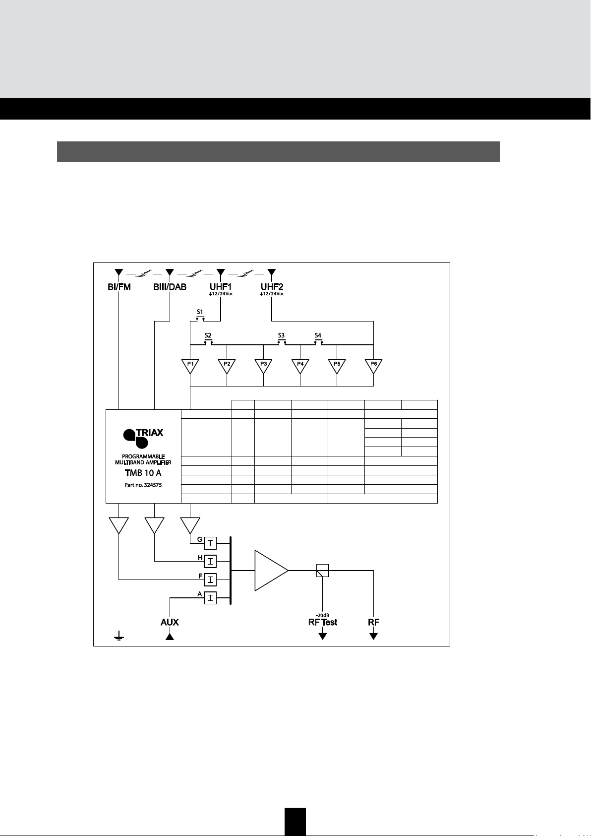
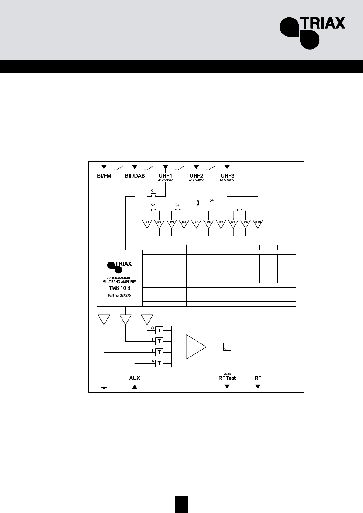
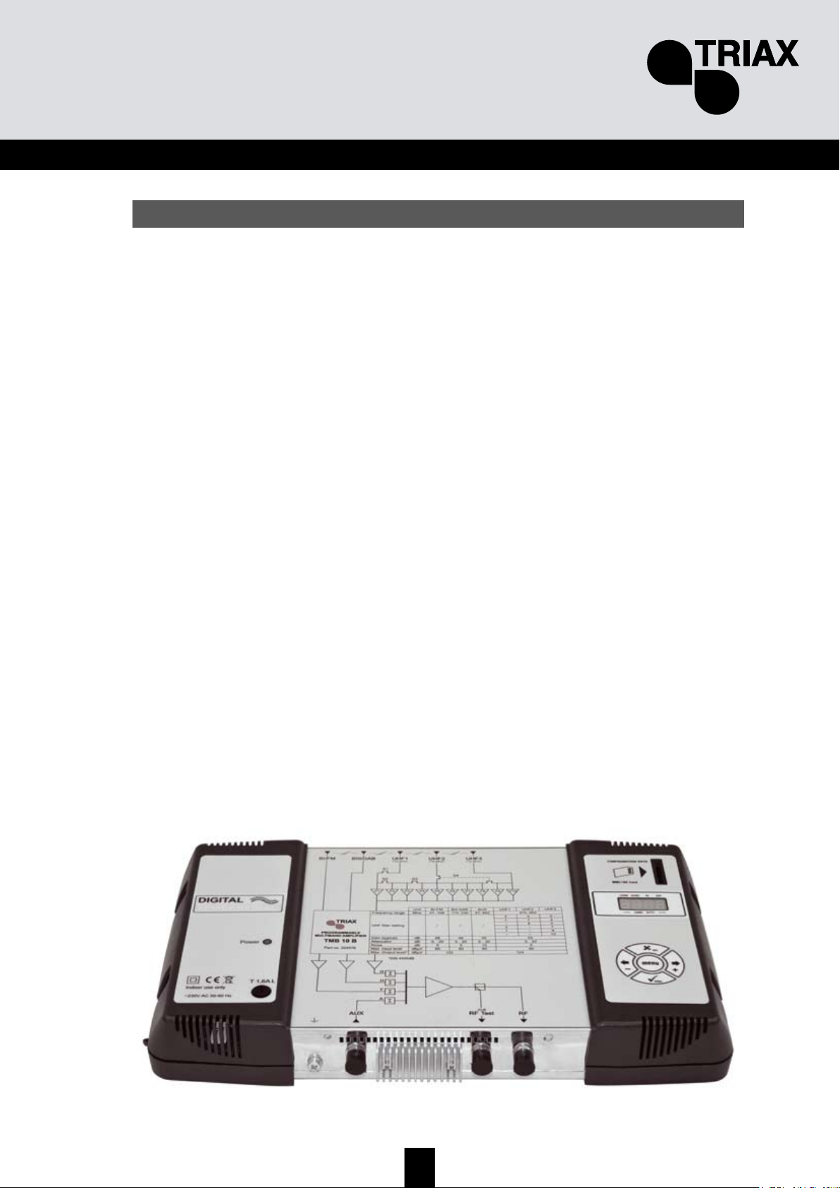
The processing units in the TMB10 range are used to selectively filter analogue and digital UHF
channels. These units also couple and amplify VHF programmes according to the satellite band model
(IF).
TMB10 units have one amplified wide band coupling input; 10 UHF filters, distributed over 3 inputs
with programmable bandwidth from 1 to 6 channels (8 to 48 MHz), making it suitable for most
situations.
An individual setting for each filter or frequency band, and automatic control of the UHF output level,
for aligning service plan levels.
TMB-10A – Ref.: 324575
5 inputs:
BI - FM, BIII - DAB, AUX, UHF1, UHF2
UHF Gain = 55 dB
BI - BIII Gain = 48 dB
AUX Gain = 39 dB
UHF output level = 124 dBµV (DIN 45004B)
TMB-10B – Ref.: 324576
6 inputs:
BI - FM, BIII - DAB, AUX, UHF1, UHF2, UHF3
UHF Gain = 55 dB
BI - BIII Gain = 48 dB
AUX Gain = 39 dB
UHF output level = 124 dBµV (DIN 45004B)
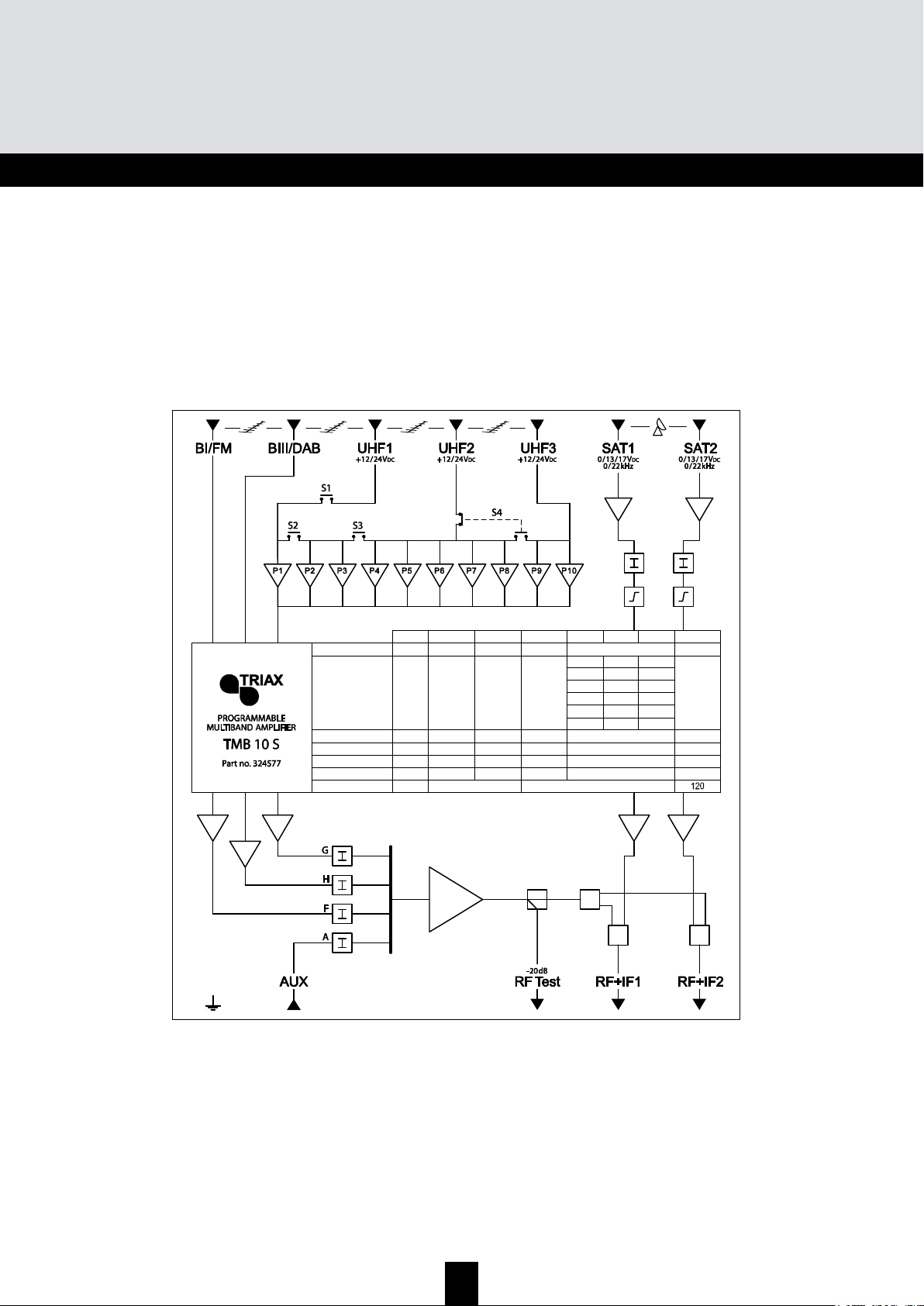
TMB-10S – Ref.: 324577
8 inputs:
BI - FM, BIII - DAB, AUX, UHF1, UHF2, UHF3, 2 x SAT
SAT Gain = 40 dB
UHF Gain = 48 dB
BI - BIII Gain = 43 dB
AUX Gain = 33 dB
UHF output level = 120 dBµV (DIN 45004B)
SAT output level = 120 dBµV (EN 50083-3)
Page 4

4
TMB Programmable Multiband Amplier
TMB 10A • TMB 10B • TMB 10S
GB
S
S
S
a
a
a
f
f
f
e
e
e
t
t
t
y
y
y
I
I
I
n
n
n
s
s
s
t
t
t
r
r
r
u
u
u
c
c
c
t
t
t
i
i
i
o
o
o
n
n
n
s
s
s
Important: The unit should only be opened by a qualified technician.
• Disconnect the unit before carrying out any work on it, as some powered components are
dangerous (risk of electrical shock).
• To maintain the temperature of the unit within its normal operating range, ensure the free
circulation of air around the unit (avoid placing it in enclosed spaces). The ventilation grids must
be free of any obstruction.
• Ensure that no liquids can penetrate inside the unit (splashes and/or run off).
• Do not install the unit in a damp place. If there are traces of condensation on the unit, do not use it
until it has dried completely.
• The mains power cable and the HF connection cables must be in good condition and free to move
(neither crushed nor obstructed).
• The mains plug, easily accessible for the technician, must be out of reach of children.
Earthing the unit
• Your aerial installation must comply with the requirements specified by the European provisions
EN 50083 (conformity of collective installations) and EN 60065 (standards in force for electrical
protection).
Replacing fuses
• Only a qualified technician can replace defective fuses.
Electromagnetic compatibility (EMC)
• Ensure that the screws on the box are properly tightened.
• Cables and connection terminals should show no signs of rust.
Page 5
5
GB
I
I
I
n
n
n
s
s
s
t
t
t
a
a
a
l
l
l
l
l
l
i
i
i
n
n
n
g
g
g
t
t
t
h
h
h
e
e
e
u
u
u
n
n
n
i
i
i
t
t
t
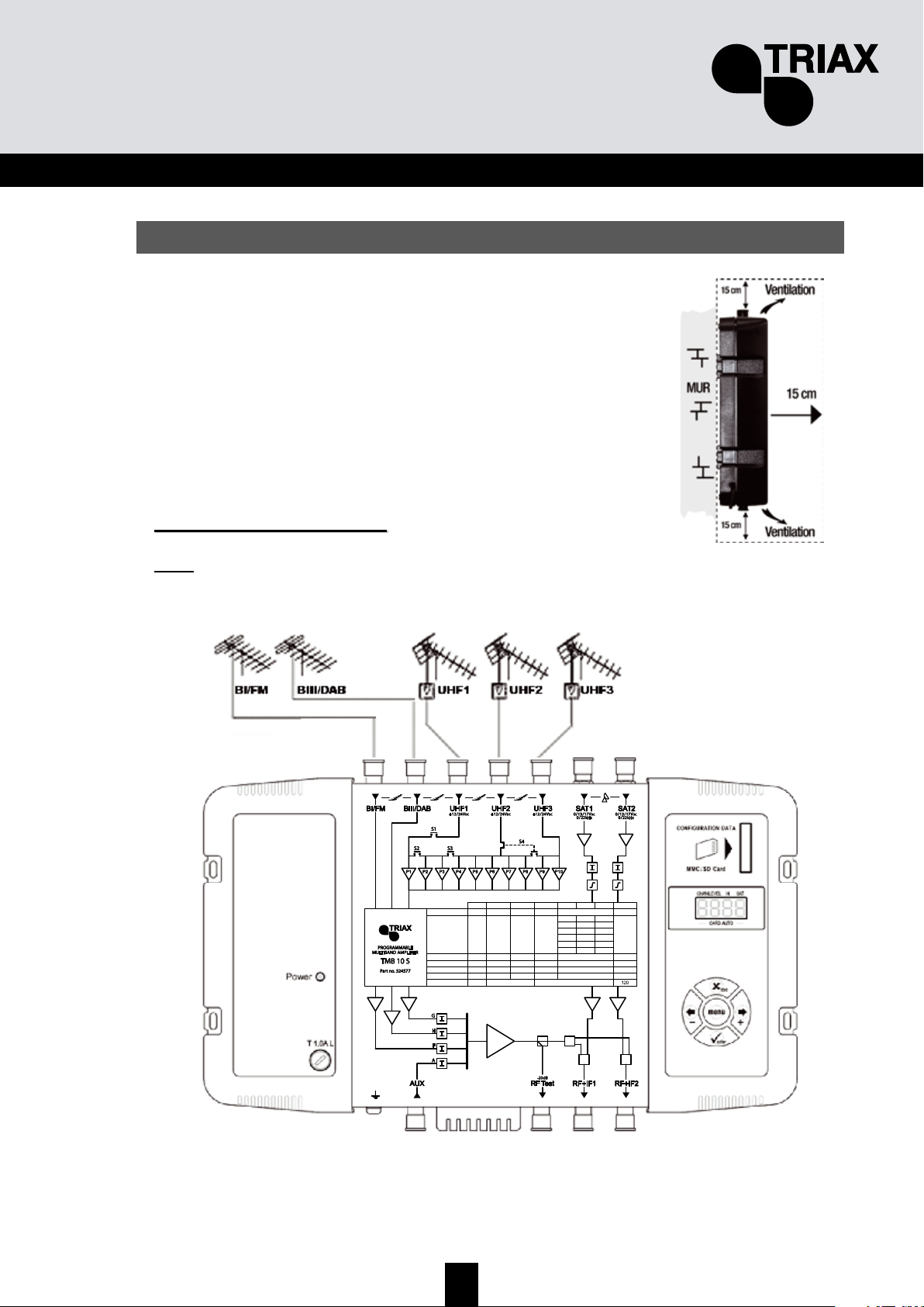
We recommend you install the unit in a sufficiently ventilated place.
Natural ventilation must be able to occur through the ventilation grids;
leave a minimum space of 15 cm around the unit to ensure maximum
ventilation.
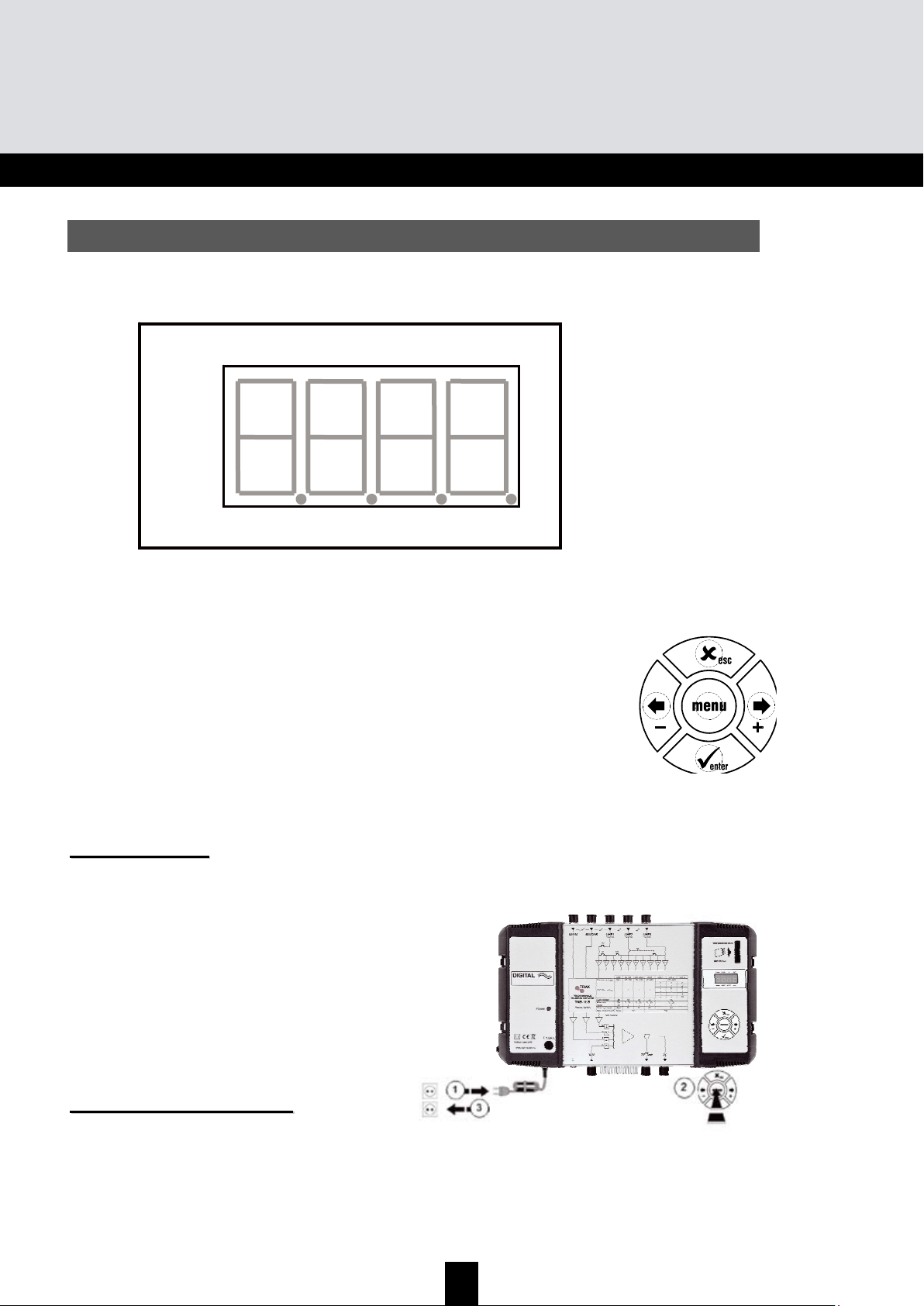
When installing or cabling the unit, we recommend you disconnect the
mains power cable.
CCoonnnneeccttiinngg tthhee uunniitt
Note:
UHF inputs are remotely supplied and protected against short circuits. The power available is
12 or 24V, 50mA max. The preamplifier is detected automatically; only the remote power voltage
can be programmed.
Max. Output level*
Max. Input level
Noise
Attenuator
Gain (typical)
UHF lter setting
Frequency range MHz
Unit
dBµV
dBµV
dB
dB
dB
47÷108
BI-FM
116
80
5
0…20
43
/
174÷230
BIII-DAB
80
5
0…20
43
/
47÷862
AUX
80
10
0…20
33
/
UHF1
120
–
1
3
–
1
3
470÷862
UHF2
80
9
0…20
48
–
–
–
8
7
5
UHF3
10
9
7
2
2
2
950÷2150
SAT
79
6
0…20
40
/
*DIN 45004B
Page 6

6
TMB Programmable Multiband Amplier
TMB 10A • TMB 10B • TMB 10S
GB
P
P
P
r
r
r
o
o
o
g
g
g
r
r
r
a
a
a
m
m
m
m
m
m
i
i
i
n
n
n
g
g
g
t
t
t
h
h
h
e
e
e
u
u
u
n
n
n
i
i
i
t
t
t
A 4-digit display and a keypad are all you need to programme the unit. Follow the procedure below
for configuring the various parameters.
When the unit is powered on:
• the programme mode is in standby:
• by default, the system is configured as follows:
o UHF1 Î 3 UHF filters
o UHF2 Î 0 UHF filters
o UHF3 Î 7 UHF filters
• all the UHF filters are deactivated (display "
- -"),
• the attenuators are at zero.
FFaaccttoorryy rreesseett
If necessary, to revert to factory settings, follow the procedure below:
1. Disconnect the power cable
2. Press the
esc button and hold it
3. Connect the power cable
The unit erases all the programming parameters,
including the PIN code, and switches to standby mode.
• You can release the
esc button when
the display shows “8888”
DDaattee ooff mmaannuuffaaccttuurree
If necessary, to consult the unit’s date of manufacture and version, press the button
- & +. For 2
seconds, the unit displays the date of manufacture in the format; A-SS with A being the last digit of
the year of manufacture, SS the week of manufacture.
Digit 1 Digit 2
Di
g
it 3
Di
g
it 4
CHAN LEVEL IN SAT
____ AUTO CARD ____
Page 7

7
GB
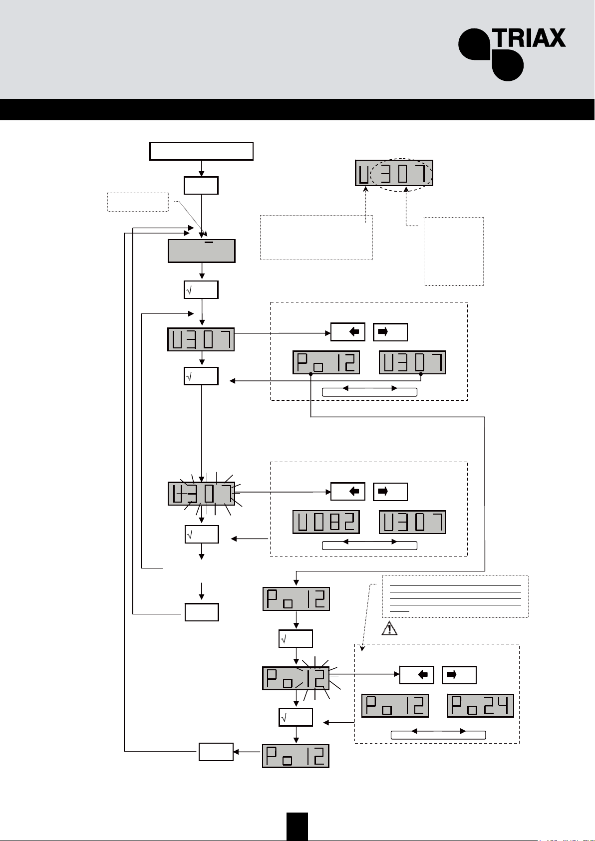
CCoonnffiigguurriinngg tthhee uunniitt
On powering on, the unit is in standby mode, a light segments flashes across the display:
O
O
O
p
p
p
e
e
e
r
r
r
a
a
a
t
t
t
i
i
i
n
n
n
g
g
g
p
p
p
r
r
r
i
i
i
n
n
n
c
c
c
i
i
i
p
p
p
l
l
l
e
e
e
To access the configuration menus, press the menu button until the light segment is under the
menu to open and press enter.
To summarize:
• To scroll through the menus, use the menu button.
• To enter a menu, press enter.
• To exit a menu, press the menu button.
Note:
If the button is not pressed for one minute, the unit switches to standby mode.
M
M
M
e
e
e
n
n
n
u
u
u
s
s
s
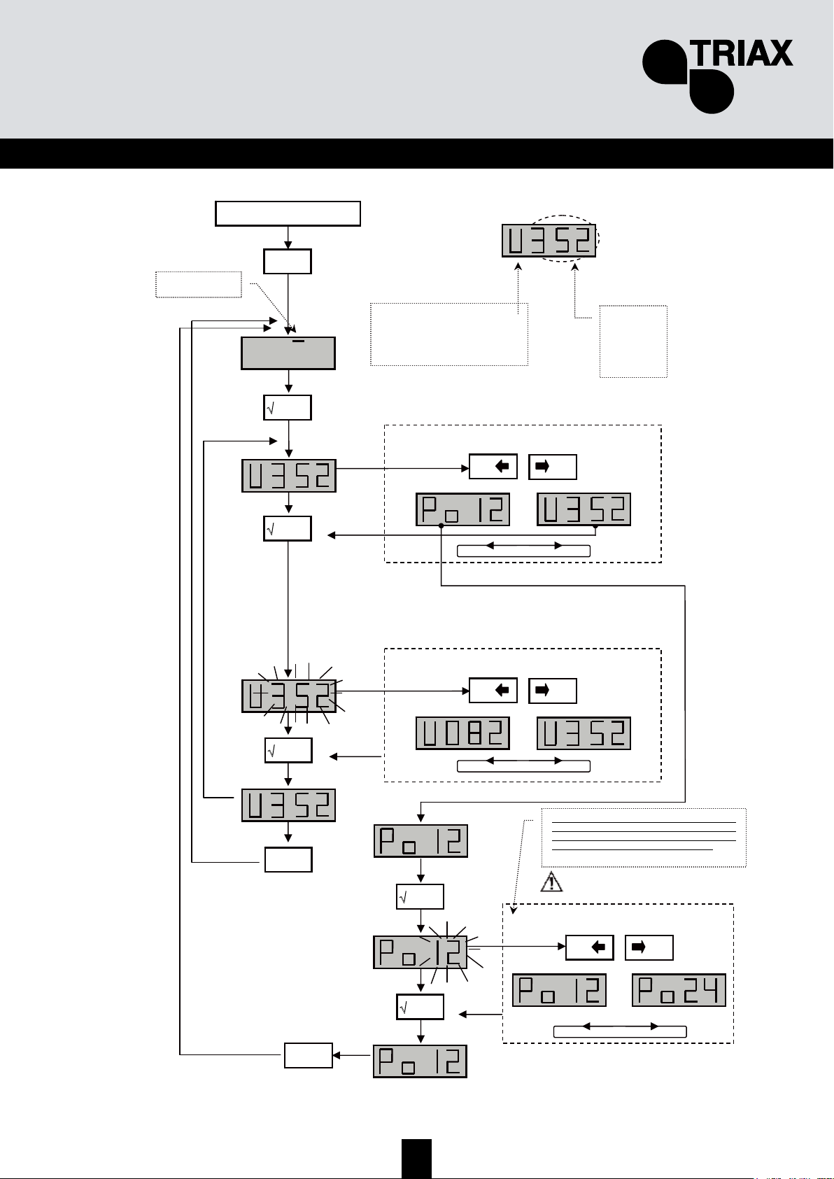
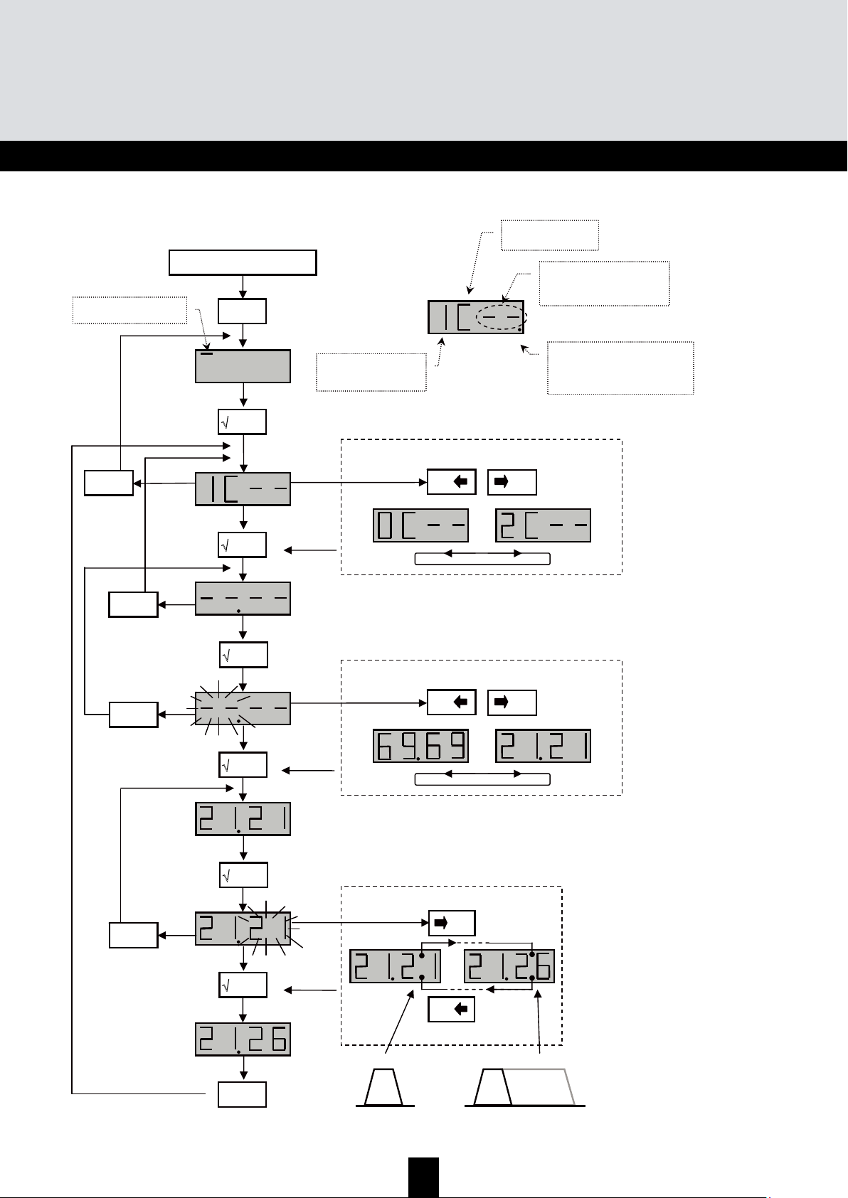
CHAN
Configuration of UHF filters:
• Channel
• Bandwidth (1 to 6 channels; 8 to 48 MHz)
LEVEL
Configuring of attenuators.
IN
Configuration of filter distribution on UHF1, 2 and 3 inputs.
Selection of remote power supply (12 or 24 V
DC
).
AUTO
Use of the AGC.
Automatic alignment of UHF programmes.
CARD
Reading and saving of configurations
Activation and configuration of the PIN code.
SAT
Configuring of IF attenuators.
9 dB equalization ON/OFF
Selection of remote power supply (0, 13 or 17 V
DC
).
Selection 22 kHz (ON/OFF).
C
C
C
H
H
H
A
A
A
N
N
N
M
M
M
e
e
e
n
n
n
u
u
u
TMB units have 6 or 10 configurable UHF filters. The UHF filters are distributed over the three
inputs UHF1, UHF2, UHF3 as shown below.
Page 8
8
TMB Programmable Multiband Amplier
TMB 10A • TMB 10B • TMB 10S
GB
TMB 10A
Input UHF1 UHF2 UHF3
423315-
-6-
Number of filters per
UHF input
TMB 10B & S
Input UHF1 UHF2 UHF3
352
172
-82
3-7
1-9
- - 10
Number of filters per
UHF input
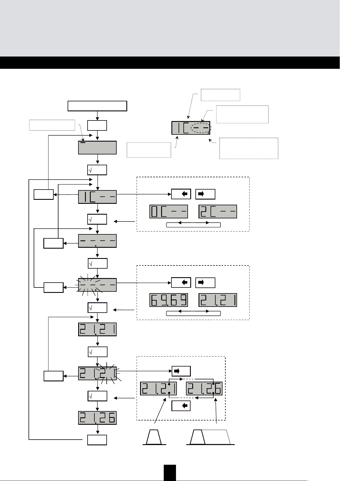
Each UHF filter can be configured for a bandwidth of 8 to 48 MHz (1 to 6 channels).
D
D
D
i
i
i
s
s
s
t
t
t
r
r
r
i
i
i
b
b
b
u
u
u
t
t
t
i
i
i
o
o
o
n
n
n
o
o
o
f
f
f
U
U
U
H
H
H
F
F
F
f
f
f
i
i
i
l
l
l
t
t
t
e
e
e
r
r
r
s
s
s
Go to the menu IN by placing the light segment under the IN mark and press enter.
• Press enter again to change the configuration of the UHF inputs (part of the display flashes)
• Press the buttons + or - to select the distribution of the filters over the UHF inputs.
Notes:
Each UHF filter can be deactivated. Just configure the filter in question to the value – in the "CHAN"
menu.
Page 9
9
GB
Start
menu
'
'
+
0
-
0
or
'
Select the sub-menu
IN – input menu
U – Distribution of UHF filters on the
inputs UHF1, UHF2 and UHF3;
Po – Selection of the remote power
supply: 12V DC or 24VDC
'
X esc
'
+
0
-
0
or
Select the distribution of UHF filters
'
+
0
-
0
or
Remote power supply
'
X
esc
/
This menu is used to select the value of the remote
power supply on the inputs UHF 1, 2 and 3. The
unit automatically detects the amplifier connected
and switches the remote power supply to ON.
Distribution of UHF filters
352
172
082
307
109
001
Remove the mains cable before any
wiring work
Page 10
10
TMB Programmable Multiband Amplier
TMB 10A • TMB 10B • TMB 10S
GB
U
U
U
H
H
H
F
F
F
f
f
f
i
i
i
l
l
l
t
t
t
e
e
e
r
r
r
w
w
w
i
i
i
d
d
d
t
t
t
h
h
h
(
(
(
C
C
C
H
H
H
A
A
A
N
N
N
m
m
m
e
e
e
n
n
n
u
u
u
)
)
)
26
21
Start
menu
'
'
X esc
'
+
0
-
0
or
'
'
'
'
'
X esc
/
X esc
/
X esc
/
X esc
/
Select the filter to configure
+
0
-
0
or
Choose the start channel
Choose the end channel
+
0
-
/
21
1 channel max. 6 channels
CHAN – menu
Filter start channel.
If the filter is not used, the
display shows “--“.
Filter number 1 to 10
(0 for filter no. 10)
The display dot flashes when the
filter has a width > 1 channel.
C – Channel menu
Page 11
11
GB
F
F
F
i
i
i
n
n
n
e
e
e
t
t
t
u
u
u
n
n
n
i
i
i
n
n
n
g
g
g
This function is used to offset the frequency of the filter concerned, to adjust the filters according to
the characteristics of the signals received (offset, adjacent channels, etc.).
Check the offset on your measurement apparatus.
Start
'
X
esc
'
0
0
The function only acts
on the filter selected
Select the filter using the
keys + and –
'
'
X esc
'
X esc
'
Page 12
12
TMB Programmable Multiband Amplier
TMB 10A • TMB 10B • TMB 10S
GB
Setting the levels.
There are three types of level setting:
• “Manual” setting of output levels (LEVEL menu)
• automatic alignment of UHF filter output levels to a value entered by the user. (Auto menu,
sub-menu LEU)
• automatic UHF gain control (Auto menu, sub-menu AGC)
C
C
C
o
o
o
n
n
n
f
f
f
i
i
i
g
g
g
u
u
u
r
r
r
i
i
i
n
n
n
g
g
g
t
t
t
h
h
h
e
e
e
a
a
a
t
t
t
t
t
t
e
e
e
n
n
n
u
u
u
a
a
a
t
t
t
o
o
o
r
r
r
s
s
s
(
(
(
L
L
L
E
E
E
V
V
V
E
E
E
L
L
L
m
m
m
e
e
e
n
n
n
u
u
u
)
)
)
Go to the LEVEL menu by placing the light segment under the LEVEL mark and press enter.
• Press the buttons + or - to select the channel to configure.
•
Confirm by pressing enter
• When the display flashes, you can configure the attenuation (20 indicates attenuation 0; 1
indicates max attenuation)
• Confirm by pressing enter
X
esc
'
Start
menu
'
'
+
0
-
0
or
'
Select sub-menu
L – level menu
Attenuation -1 to -20 dB
L – for LEVEL menu
1…0 – filter number, from 1 to 10
H – VHF band (BIII)
F – FM band (BI/FM)
A – auxiliary input (AUX)
G – UHF Gain
+
0
-
0
or
Choose the attenuation
'
Page 13
13
GB
A
A
A
u
u
u
t
t
t
o
o
o
m
m
m
a
a
a
t
t
t
i
i
i
c
c
c
U
U
U
H
H
H
F
F
F
g
g
g
a
a
a
i
i
i
n
n
n
c
c
c
o
o
o
n
n
n
t
t
t
r
r
r
o
o
o
l
l
l
A
A
A
u
u
u
t
t
t
o
o
o
m
m
m
e
e
e
n
n
n
u
u
u
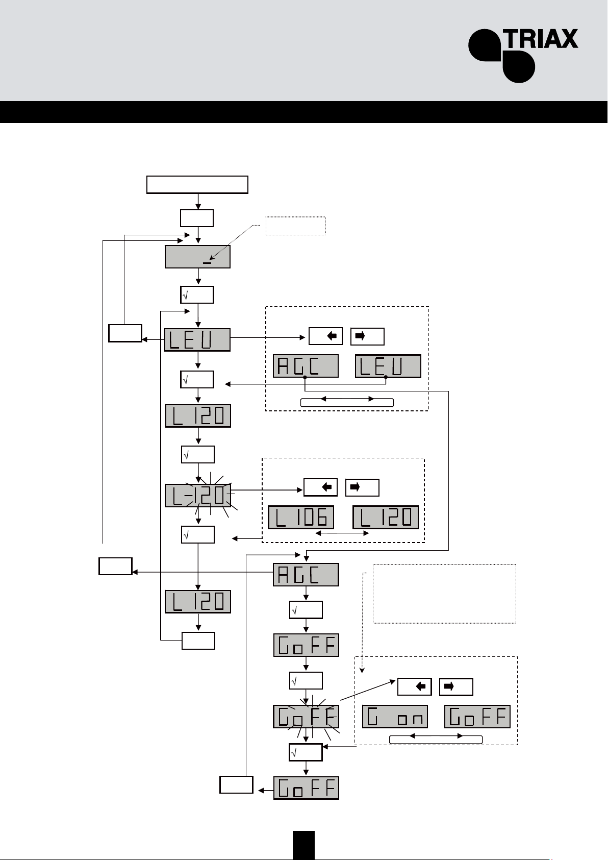
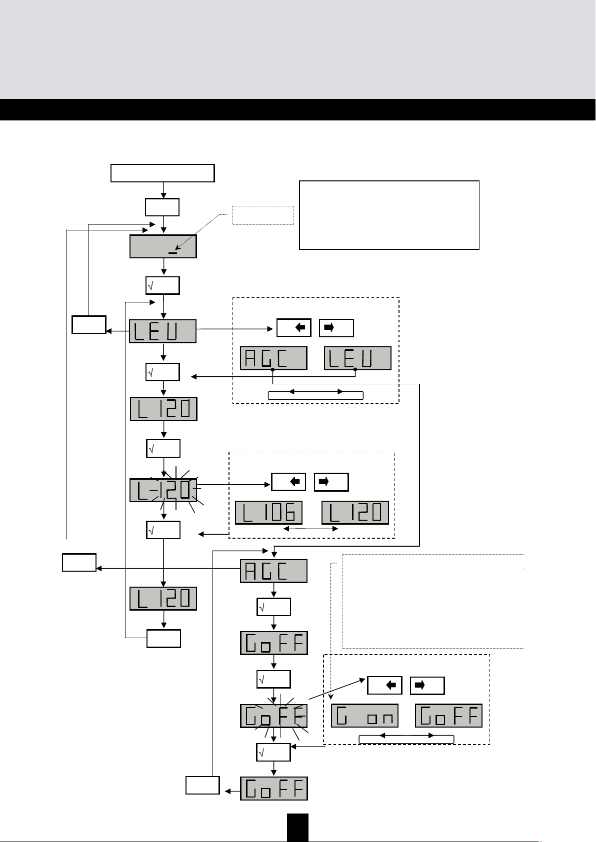
Note: Setting of the levels BI-II / BIII / AUX is not automatic.
Start
menu
'
'
'
AUTO – menu
√ enter
'
+
0
-
0
or
√ enter
'
Display the value of the output level
X
esc
'
X esc
'
min. max.
+
0
-
0
or
Select the sub-menu
'
'
+
0
-
0
or
'
X esc
'
X esc
'
IMPORTANT!
The unit memorizes the average output level. A
variation of ± 1 dB triggers the function and
compensates the variation within gain and
attenuation limits
AGC mode hides all other menus. To modify the
parameters, switch the AGC mode to OFF.
Page 14
14
TMB Programmable Multiband Amplier
TMB 10A • TMB 10B • TMB 10S
GB
C
C
C
A
A
A
R
R
R
D
D
D
M
M
M
e
e
e
n
n
n
u
u
u
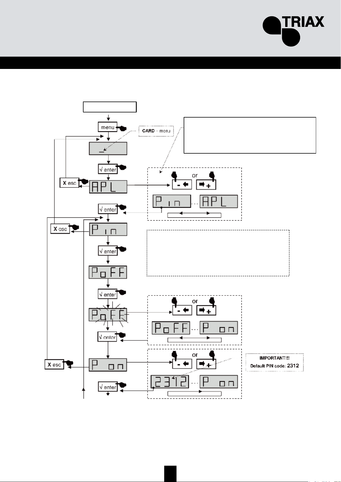
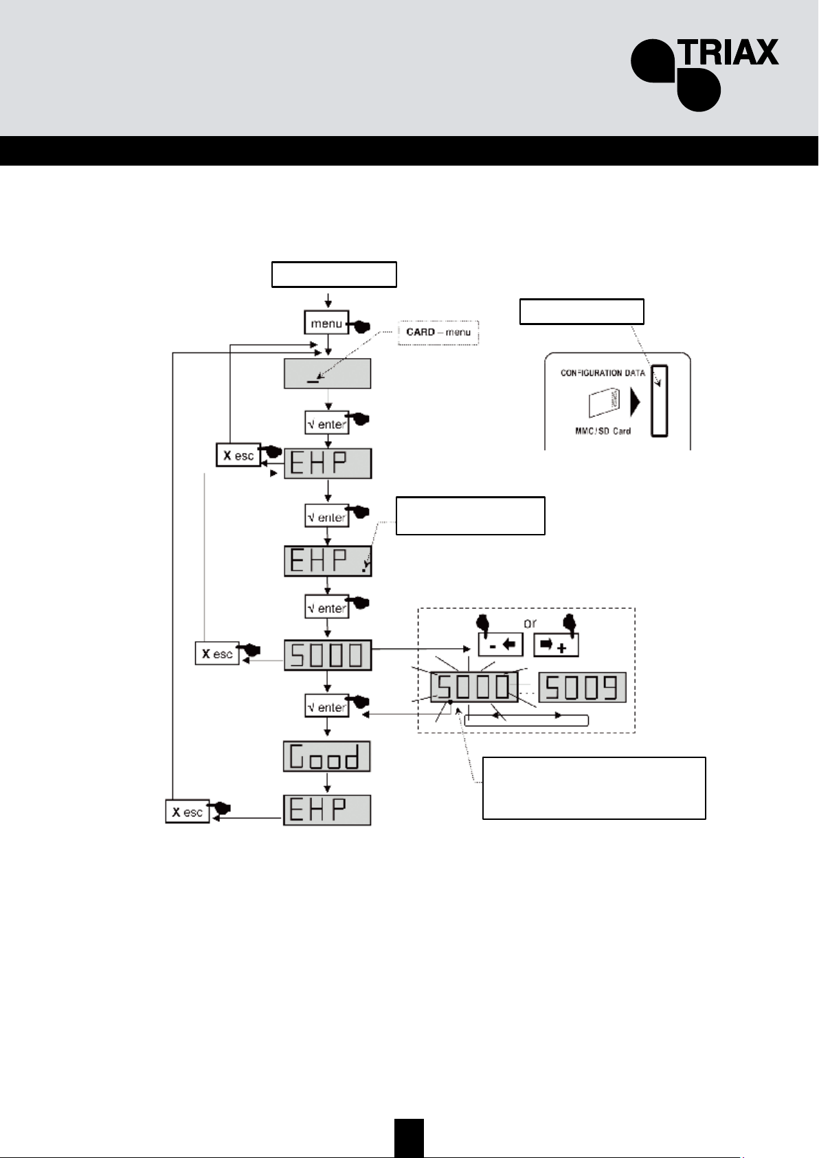
TMB units have an SD/MMC interface to save or read configurations and for updating the product.
This menu includes 4 sub-menus:
• APL updating of the firmware
When the card contains the update file (tm_tmb10.tlp), and the enter key is pressed; the update
occurs automatically and the display shows "boot" during the whole operation.
• EHP data memorization
Select the sub-menu and choose a filename. The display flashes when the file already exists. By
pressing the enter key, it is “overwritten".
• InP read the configuration files
Select the sub-menu and display the name of the file to read. When the key is pressed, reading
starts; the display shows "Good" when the procedure is complete.
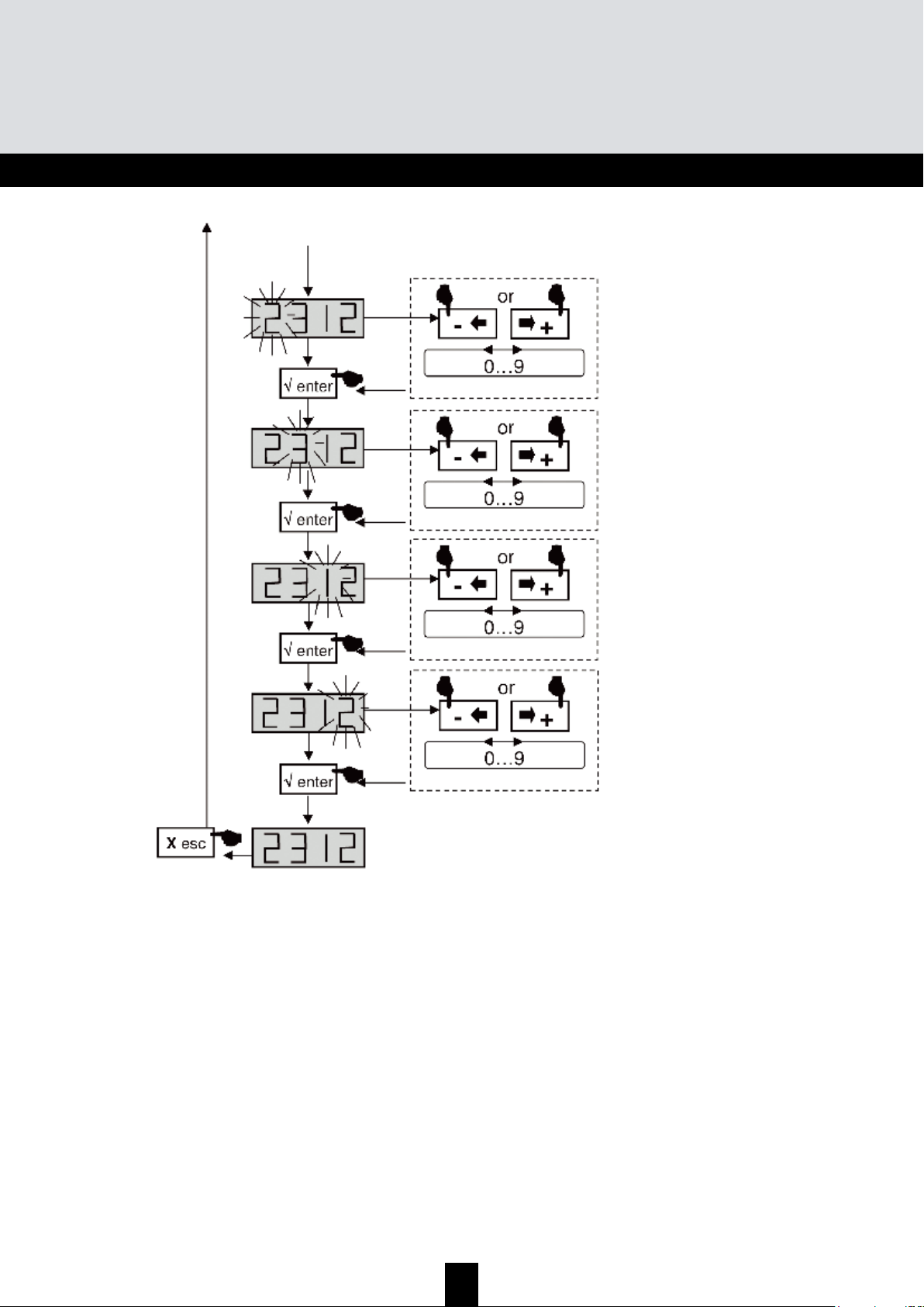
• PIN activation and configuration of the PIN code
When this function is active, the PIN code is requested to access the menus (display your PIN code
using the keypad and confirm by pressing enter). If no key is pressed for 30 seconds, the unit
switches to standby mode and the PIN code must be entered again to access the menus.
Important.
• When no SD card is inserted in the unit, the display indicates Err when one of the menus
APL, EHP or InP is used.
• The SD/MMC card must be formatted in FAT16. The files should be placed in the root
directory.
• The configuration files are names specifically according to the model number (S00x for
TMB10S, B00x for TMB10B, A00x for TMB10A).
• The default PIN code is 2312.
Page 15
15
GB
CARD Menu
Start
Continued on next page
APL firmware update
EHP data memorization
InP read configuration files
PIN activation and configuration of the PIN code
The SD/MMC card must be formatted in FAT 16.
The files should be placed in the root directory.
If the SD/MMC card has no configuration file the
display will show noFL during reboot.
Select the sub-menu
Page 16
16
TMB Programmable Multiband Amplier
TMB 10A • TMB 10B • TMB 10S
GB
Continued from the previous page
Page 17
17
GB
EHP Export Menu
Start
Insert the SD card
The dot flashes when the
process begins
When the display flashes, the file has
been created on the SD card.
Press “enter”, to confirm and overwrite
the existing file.
Select the file to read
Page 18
18
TMB Programmable Multiband Amplier
TMB 10A • TMB 10B • TMB 10S
GB
InP Import
Menu
Start
Insert the SD card
Select the file to read
The dot flashes when the
process begins
Page 19
19
GB
S
S
S
A
A
A
T
T
T
M
M
M
e
e
e
n
n
n
u
u
u
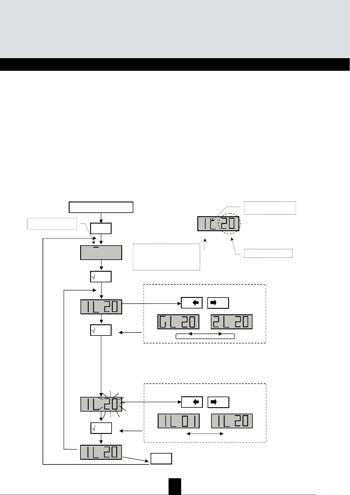
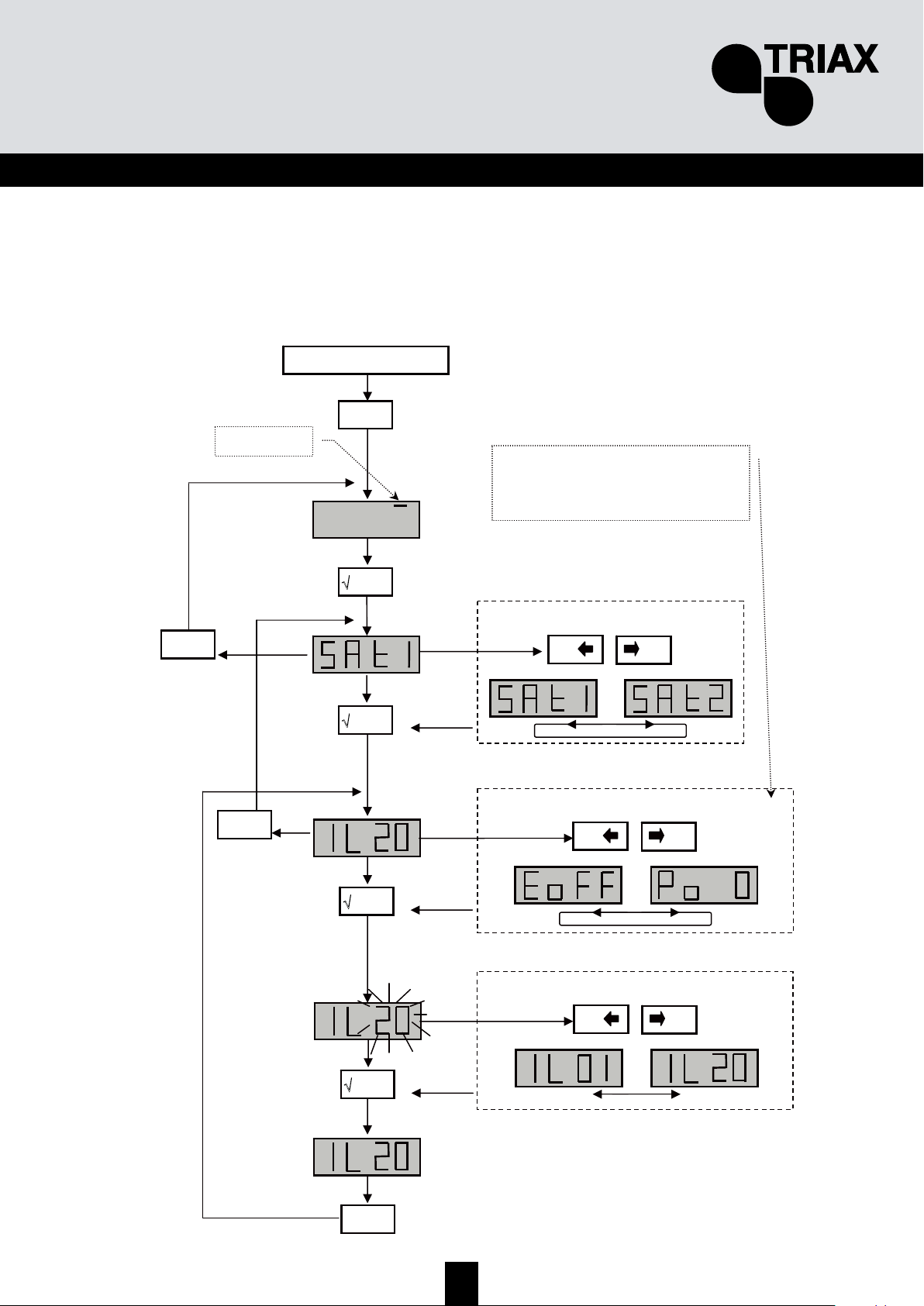
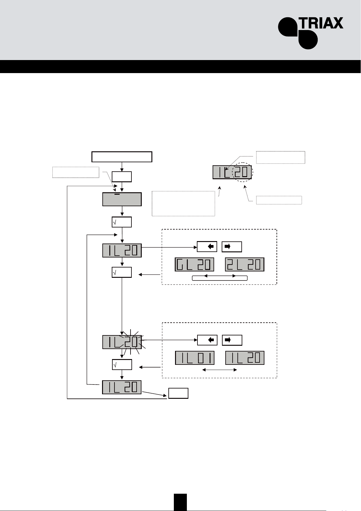
• TMB 10S models have two IF amplification channels. The Sat menu is used to configure the
remote power supply of the LNB (OFF / 13 /17 V
DC
), to activate the 22kHz generator and
the 9dB equalizer.
Start
menu
'
'
+
0
-
0
or
'
Select the channel to configure
SAT – menu
+
0
-
0
or
√ enter
'
+
0
-
0
or
Select the sub-menu
√ enter
'
Display the value
X esc
'
X esc
'
X esc
'
IL – adjust the output level
Po – LNB supply: 0, 13 or 17V
DC
to – 22kHz generator on / off
E – equalizer on / off,
Page 20
20
TMB Programmable Multiband Amplier
TMB 10A • TMB 10B • TMB 10S
GB
D
D
D
i
i
i
a
a
a
g
g
g
r
r
r
a
a
a
m
m
m
s
s
s
Diagram TMB-10A
Max. Output level*
Max. Input level
Noise
Attenuator
Gain (typical)
UHF filter setting
Frequency range MHz
Unit
dBµV
dBµV
dB
dB
dB
47÷108
BI-FM
122
80
5
0…20
48
/
174÷230
BIII-DAB
80
5
0…20
48
/
47÷862
AUX
80
10
0…20
39
/
124
80
9
0…20
55
UHF1
1
4
470÷862
UHF2
5
3
2
3
–6
*DIN 45004B
Page 21
21
GB
Diagram TMB-10B
Max. Output level*
Max. Input level
Noise
Attenuator
Gain (typical)
UHF filter setting
Frequency range MHz
Unit
dBµV
dBµV
dB
dB
dB
47÷108
BI-FM
122
80
5
0…20
48
/
174÷230
BIII-DAB
80
5
0…20
48
/
47÷862
AUX
80
10
0…20
39
/
UHF1
124
–
1
3
–
1
3
470÷862
UHF2
80
9
0…20
55
–
–
–
8
7
5
UHF3
10
9
7
2
2
2
*DIN 45004B
Page 22
22
TMB Programmable Multiband Amplier
TMB 10A • TMB 10B • TMB 10S
GB
Diagram TMB-10S
Max. Output level*
Max. Input level
Noise
Attenuator
Gain (typical)
UHF filter setting
Frequency range MHz
Unit
dBµV
dBµV
dB
dB
dB
47÷108
BI-FM
116
80
5
0…20
43
/
174÷230
BIII-DAB
80
5
0…20
43
/
47÷862
AUX
80
10
0…20
33
/
UHF1
120
–
1
3
–
1
3
470÷862
UHF2
80
9
0…20
48
–
–
–
8
7
5
UHF3
10
9
7
2
2
2
950÷2150
SAT
79
6
0…20
40
/
*DIN 45004B
Page 23
23
GB
T
T
T
e
e
e
c
c
c
h
h
h
n
n
n
i
i
i
c
c
c
a
a
a
l
l
l
S
S
S
p
p
p
e
e
e
c
c
c
i
i
i
f
f
f
i
i
i
c
c
c
a
a
a
t
t
t
i
i
i
o
o
o
n
n
n
s
s
s
Name TMB-10A TMB-10B TMB-10S
Reference / part number
Units
324575 324576 324577
Number of inputs
5 6 8
AMPLIFICATION
Max. VHF/UHF input level
dB 80/80
BI/FM input gain
dB 48 43
BIII/DAB input gain
dB 48 43
AUX input gain
dB 39 33
Preacc. VHF/UHF input
dB 5
UHF 1/2/3 inputs gain
dB 55 / 55 /- 55 / 55 / 55 48 / 48 / 48
SAT 1 and SAT 2 input gain
dB 40
Preacc. SAT inputs
dB 9 (switchable)
BIII / UHF / SAT Noise factor
dB 5 / 9 / - 5 / 9 / 6
Attenuator per input
dB 0 to 20
Global UHF output attenuator
dB 0 to 20
UHF output adjustment by AGC
dB -9 to +10
Max. Output level VHF / UHF/ SAT
(DIN45004B)
dBµV 122 / 124 / - 116 / 120 / 120
Test output
dB -20
FILTERING
Distribution of filters
See page 7 of this
manual
Width of filtering channels
MHz 8 to 48
selectivity of filters at +/- 16MHz
dB 16
Adaptation of inputs
dB >10
Adaptation of outputs
dB >10
POWER SUPPLY
Voltage
VAC 230
Power consumption at 230VAC
VA 35
Remote supply UHF1,2 or 3
VDC/mA 12 or 24 /55
Equipped inputs
UHF 1 and 2 UHF 1, 2 and 3
LNB supply
VDC/mA 0,13 or 17 /300
22kHz generator
ON / OFF
SAT inputs equipped
SAT 1 and 2
Test output
dB -20
Operating temperature
ºC -5 to +50
MECHANICS
Input/output connectors
"F" female
Dimensions (H x W x D)
mm 225 x 360 x 50
Filter data.
Page 24
24
TMB Programmable Multiband Amplier
TMB 10A • TMB 10B • TMB 10S
GB
in pu t o ut pu t T e s t
BI - BII 47 to 1 08 M Hz
BIII 17 4 to 24 0 M Hz
V HF- UHF
47
to
24 0
& 47 0 t o 86 2 M Hz
F i l te r 1
( 1 t o 6 c ha nn e ls ) 8 t o 48
M Hz
F i l te r 2
( 1 t o 6 c ha nn e ls ) 8 t o 48
M Hz
F i l te r 3
( 1 t o 6 c ha nn e ls ) 8 t o 48
M Hz
F i l te r 4
( 1 t o 6 c ha nn e ls ) 8 t o 48
M Hz
F i l te r 5
( 1 t o 6 c ha nn e ls ) 8 t o 48
M Hz
F i l te r 6
( 1 t o 6 c ha nn e ls ) 8 t o 48
M Hz
F i l te r 7
( 1 t o 6 c ha nn e ls ) 8 t o 48
M Hz
F i l te r 8
( 1 t o 6 c ha nn e ls ) 8 t o 48
M Hz
F i l te r 9
( 1 t o 6 c ha nn e ls ) 8 t o 48
M Hz
F i l te r 1 0
(1 to 6 ch an n e ls ) 8 to 4 8
M Hz
L e ve lsUHF1
1 o r 3 filte r s
UHF2
5 , 7 o r 8 filte r s
UHF3
2, 7, 9 o r 10
Filte r w id th
Page 25

25
GB
General information .............................................................................................................................. 2
Safety Instructions ................................................................................................................................3
Installing the unit................................................................................................................................... 4
CCoonnnneeccttiinngg tthhee uunniit
t ............................................................................................................................. 4
Programming the unit ........................................................................................................................... 5
FFaaccttoorryy rreesseet
t ....................................................................................................................................... 5
DDaattee ooff mmaannuuffaaccttuurre
e............................................................................................................................ 5
CCoonnffiigguurriinngg tthhee uunniit
t ............................................................................................................................. 6
O
O
O
p
p
p
e
e
e
r
r
r
a
a
a
t
t
t
i
i
i
n
n
n
g
g
g
p
p
p
r
r
r
i
i
i
n
n
n
c
c
c
i
i
i
p
p
p
l
l
l
e
e
e
.......................................................................................................................... 6
Menus ..................................................................................................................................................... 6
CHAN.......................................................................................................................................... 6
LEVEL ........................................................................................................................................ 6
C
C
C
H
H
H
A
A
A
N
N
N
M
M
M
e
e
e
n
n
n
u
u
u
.................................................................................................................................... 6
D
D
D
i
i
i
s
s
s
t
t
t
r
r
r
i
i
i
b
b
b
u
u
u
t
t
t
i
i
i
o
o
o
n
n
n
o
o
o
f
f
f
U
U
U
H
H
H
F
F
F
f
f
f
i
i
i
l
l
l
t
t
t
e
e
e
r
r
r
s
s
s
................................................................................................................ 7
U
U
U
H
H
H
F
F
F
f
f
f
i
i
i
l
l
l
t
t
t
e
e
e
r
r
r
w
w
w
i
i
i
d
d
d
t
t
t
h
h
h
(
(
(
C
C
C
H
H
H
A
A
A
N
N
N
m
m
m
e
e
e
n
n
n
u
u
u
)
)
)
........................................................................................................ 9
F
F
F
i
i
i
n
n
n
e
e
e
t
t
t
u
u
u
n
n
n
i
i
i
n
n
n
g
g
g
.................................................................................................................................... 10
C
C
C
o
o
o
n
n
n
f
f
f
i
i
i
g
g
g
u
u
u
r
r
r
i
i
i
n
n
n
g
g
g
t
t
t
h
h
h
e
e
e
a
a
a
t
t
t
t
t
t
e
e
e
n
n
n
u
u
u
a
a
a
t
t
t
o
o
o
r
r
r
s
s
s
(
(
(
L
L
L
E
E
E
V
V
V
E
E
E
L
L
L
m
m
m
e
e
e
n
n
n
u
u
u
)
)
)
.................................................................................. 11
A
A
A
u
u
u
t
t
t
o
o
o
m
m
m
a
a
a
t
t
t
i
i
i
c
c
c
U
U
U
H
H
H
F
F
F
g
g
g
a
a
a
i
i
i
n
n
n
c
c
c
o
o
o
n
n
n
t
t
t
r
r
r
o
o
o
l
l
l
A
A
A
u
u
u
t
t
t
o
o
o
m
m
m
e
e
e
n
n
n
u
u
u
....................................................................................... 12
C
C
C
A
A
A
R
R
R
D
D
D
M
M
M
e
e
e
n
n
n
u
u
u
.................................................................................................................................. 13
S
S
S
A
A
A
T
T
T
M
M
M
e
e
e
n
n
n
u
u
u
..................................................................................................................................... 18
Diagrams .............................................................................................................................................. 19
Technical Specifications..................................................................................................................... 22
Notes....................................................................................................................................................... 1
Page 26

26
TMB Centrales programmables • Notice d’utilisation
TMB 10A • TMB 10B • TMB 10S
FR
Généralités ............................................................................................................................................. 2
Consignes de sécurité .......................................................................................................................... 3
Installation de la centrale...................................................................................................................... 4
RRaaccccoorrddeemmeenntt ddee llaa cceennttrraalle
e .............................................................................................................. 4
Programmation de la centrale.............................................................................................................. 5
RReesseett uussiinne
e ......................................................................................................................................... 5
DDaattee ddee ffaabbrriiccaattiioon
n ..............................................................................................................................5
CCoonnffiigguurraattiioonn ddee llaa cceennttrraalle
e ................................................................................................................ 6
P
P
P
r
r
r
i
i
i
n
n
n
c
c
c
i
i
i
p
p
p
e
e
e
d
d
d
e
e
e
f
f
f
o
o
o
n
n
n
c
c
c
t
t
t
i
i
i
o
o
o
n
n
n
n
n
n
e
e
e
m
m
m
e
e
e
n
n
n
t
t
t
............................................................................................................ 6
Menus ..................................................................................................................................................... 6
CHAN.......................................................................................................................................... 6
LEVEL......................................................................................................................................... 6
M
M
M
e
e
e
n
n
n
u
u
u
C
C
C
H
H
H
A
A
A
N
N
N
.................................................................................................................................... 7
R
R
R
é
é
é
p
p
p
a
a
a
r
r
r
t
t
t
i
i
i
t
t
t
i
i
i
o
o
o
n
n
n
d
d
d
e
e
e
s
s
s
f
f
f
i
i
i
l
l
l
t
t
t
r
r
r
e
e
e
s
s
s
U
U
U
H
H
H
F
F
F
.............................................................................................................. 7
L
L
L
a
a
a
r
r
r
g
g
g
e
e
e
u
u
u
r
r
r
d
d
d
e
e
e
s
s
s
f
f
f
i
i
i
l
l
l
t
t
t
r
r
r
e
e
e
s
s
s
U
U
U
H
H
H
F
F
F
(
(
(
m
m
m
e
e
e
n
n
n
u
u
u
C
C
C
H
H
H
A
A
A
N
N
N
)
)
)
........................................................................................... 9
R
R
R
é
é
é
g
g
g
l
l
l
a
a
a
g
g
g
e
e
e
f
f
f
i
i
i
n
n
n
.................................................................................................................................... 10
C
C
C
o
o
o
n
n
n
f
f
f
i
i
i
g
g
g
u
u
u
r
r
r
a
a
a
t
t
t
i
i
i
o
o
o
n
n
n
d
d
d
e
e
e
s
s
s
a
a
a
t
t
t
t
t
t
é
é
é
n
n
n
u
u
u
a
a
a
t
t
t
e
e
e
u
u
u
r
r
r
s
s
s
(
(
(
m
m
m
e
e
e
n
n
n
u
u
u
L
L
L
E
E
E
V
V
V
E
E
E
L
L
L
)
)
)
............................................................................ 12
C
C
C
o
o
o
n
n
n
t
t
t
r
r
r
ô
ô
ô
l
l
l
e
e
e
a
a
a
u
u
u
t
t
t
o
o
o
m
m
m
a
a
a
t
t
t
i
i
i
q
q
q
u
u
u
e
e
e
d
d
d
u
u
u
g
g
g
a
a
a
i
i
i
n
n
n
d
d
d
e
e
e
s
s
s
f
f
f
i
i
i
l
l
l
t
t
t
r
r
r
e
e
e
s
s
s
U
U
U
H
H
H
F
F
F
M
M
M
e
e
e
n
n
n
u
u
u
A
A
A
U
U
U
T
T
T
O
O
O
........................................................ 13
M
M
M
e
e
e
n
n
n
u
u
u
C
C
C
A
A
A
R
R
R
D
D
D
.................................................................................................................................. 14
M
M
M
e
e
e
n
n
n
u
u
u
S
S
S
A
A
A
T
T
T
..................................................................................................................................... 19
Caractéristiques techniques .............................................................................................................. 20
Synoptiques ......................................................................................................................................... 22
Notes..................................................................................................................................................... 22
Page 27
27
FR
G
G
G
é
é
é
n
n
n
é
é
é
r
r
r
a
a
a
l
l
l
i
i
i
t
t
t
é
é
é
s
s
s
Les stations de traitement de la gamme TMB10, permettent un filtrage sélectif des canaux UHF
numériques et analogiques. Le couplage et l'amplification de canaux VHF sont également assurés par
ces stations. Le modèle TMB10S permet également l’amplification de deux bandes BIS (programmes
satellites).
Les stations de traitement TMB10 sont équipées de 6 à 10 filtres UHF à répartir sur 2 ou 3 entrées et
une entrée de couplage large bande amplifiée.
La largeur de bande des filtres est configurable par programmation de 1 à 6 canaux (8 à 48 MHz),
permettant de répondre à la plupart des situations rencontrées.
Un réglage de gain individuel pour chaque filtre ou bande de fréquences, ainsi qu'un contrôle
automatique du niveau de sortie UHF, permettent d'aligner les niveaux du plan de service.
TMB-10A – Réf. : 324575
5 entrées : BI + FM, BIII, UHF1, UHF2, AUX (VHF - UHF)
6 filtres UHF réglables, à répartir sur les entrées UHF1 et 2
Gain UHF = 55 dB
Gain BIII = 48 dB
Gain de couplage entrée AUX = 40 dB
Niveau de sortie UHF = 124 dBµV (DIN 45004B)
TMB-10B – Réf. : 324576
6 entrées : BI + FM, BIII, UHF1, UHF2, UHF3, AUX (VHF - UHF)
10 filtres UHF réglables, à répartir sur les entrées UHF1, 2 et 3
Gain UHF = 55 dB
Gain BIII = 48 dB
Gain de couplage entrée AUX = 40 dB
Niveau de sortie UHF = 124 dBµV (DIN 45004B)
TMB-10S – Réf. : 324577
8 entrées : BI + FM, BIII, UHF1, UHF2, UHF3, AUX (VHF - UHF), 2 * BIS
10 filtres UHF réglables, à répartir sur les entrées UHF1, 2 et 3
Gain BIS = 40 dB
Gain UHF = 48 dB
Gain BIII = 43 dB
Gain de couplage entrée AUX = 33 dB
Niveau de sortie UHF = 120 dBµV (DIN 45004B)
Niveau de sortie SAT = 120 dBµV (EN 50083-3)
Page 28

28
TMB Centrales programmables • Notice d’utilisation
TMB 10A • TMB 10B • TMB 10S
FR
C
C
C
o
o
o
n
n
n
s
s
s
i
i
i
g
g
g
n
n
n
e
e
e
s
s
s
d
d
d
e
e
e
s
s
s
é
é
é
c
c
c
u
u
u
r
r
r
i
i
i
t
t
t
é
é
é
Important : l’appareil ne doit être ouvert que par un technicien qualifié.
• Débranchez l’appareil avant toute intervention, car certains composants sous tension sont
dangereux (risque d’électrocution).
• Pour maintenir la température de l’appareil dans sa plage de fonctionnement normal, veillez à ce
que l’air puisse circuler librement autour de l’appareil (éviter les emplacements trop exigus). Les
ouïes de ventilation doivent être entièrement libres de toute obstruction.
• Veillez à ce qu’aucun liquide ne puisse pénétrer à l’intérieur de l’appareil (projection et/ou
ruissellement).
• N'installez pas l'appareil dans un endroit humide. Si l'appareil présente des traces de
condensation, ne pas l’utiliser avant qu’il ne soit entièrement sec.
• Le cordon d’alimentation secteur et les câbles de raccordement HF doivent être en bon état,
parfaitement libres (ni écrasés, ni coincés).
• La prise secteur, facile d’accès pour le technicien, doit être située hors de portée des enfants.
Mise à la terre de l’installation
• Votre installation d’antennes doit être conforme aux exigences définies par les dispositions
européennes EN 50083 (conformité des installations collectives) et EN 60065 (normes en vigueur
pour la protection électrique).
Remplacement des fusibles
• Seul un technicien qualifié pourra effectuer le remplacement des fusibles défectueux.
Compatibilité électromagnétique (CEM)
• Veillez au bon serrage des vis du boîtier.
• Les câbles et les bornes de connexion ne doivent pas être oxydés.
Page 29

29
FR
I
I
I
n
n
n
s
s
s
t
t
t
a
a
a
l
l
l
l
l
l
a
a
a
t
t
t
i
i
i
o
o
o
n
n
n
d
d
d
e
e
e
l
l
l
a
a
a
c
c
c
e
e
e
n
n
n
t
t
t
r
r
r
a
a
a
l
l
l
e
e
e
Nous conseillons d'installer la centrale dans un endroit suffisamment
ventilé. Une ventilation naturelle doit pouvoir s'effectuer par les ouïes de
ventilation ; laisser un espace minimum de 15 cm autour du produit pour
garantir une ventilation maximale.
Pour une intervention de montage ou de câblage, nous vous
recommandons de retirer le cordon secteur.
RRaaccccoorrddeemmeenntt ddee llaa cceennttrraallee
Remarque
: Les entrées UHF disposent d'une téléalimentation ainsi que d'une protection contre les
courts-circuits. La tension disponible est de 12 ou 24V, 55mA max. La détection du préamplificateur
se fait automatiquement; seul le choix de la tension de téléalimentation est programmable.
Max. Output level*
Max. Input level
Noise
Attenuator
Gain (typical)
UHF lter setting
Frequency range MHz
Unit
dBµV
dBµV
dB
dB
dB
47÷108
BI-FM
116
80
5
0…20
43
/
174÷230
BIII-DAB
80
5
0…20
43
/
47÷862
AUX
80
10
0…20
33
/
UHF1
120
–
1
3
–
1
3
470÷862
UHF2
80
9
0…20
48
–
–
–
8
7
5
UHF3
10
9
7
2
2
2
950÷2150
SAT
79
6
0…20
40
/
*DIN 45004B
Page 30
30
TMB Centrales programmables • Notice d’utilisation
TMB 10A • TMB 10B • TMB 10S
FR
P
P
P
r
r
r
o
o
o
g
g
g
r
r
r
a
a
a
m
m
m
m
m
m
a
a
a
t
t
t
i
i
i
o
o
o
n
n
n
d
d
d
e
e
e
l
l
l
a
a
a
c
c
c
e
e
e
n
n
n
t
t
t
r
r
r
a
a
a
l
l
l
e
e
e
Un afficheur 4 digits et un clavier suffisent pour programmer la centrale. Vous trouverez ci-dessous
la procédure à suivre pour configurer les différents paramètres.
A la mise sous tension de l'appareil :
• le mode programmation est en stand-by :
• sans modification de programmation, le système est configuré comme suit :
TMB 10B & TMB 10S
o UHF1 Î 3 filtres UHF
o UHF2 Î 0 filtres UHF
o UHF3 Î 7 filtres UHF
TMB A
o UHF1 Î 4 filtres UHF
o UHF2 Î 2 filtres UHF
• tous les filtres UHF sont désactivés (affichage "
- -"),
• les atténuateurs sont à zéro.
RReesseett uussiinnee
Pour revenir, en cas de besoin, à la programmation usine, il suffit de suivre la procédure ci-dessous:
1. Débranchez le cordon secteur
2. Appuyez sur le bouton
esc et maintenez la position
3. Branchez le cordon secteur
Le module efface tous les paramètres de programmation,
y compris le code PIN, puis se met en mode veille.
• Vous pouvez relâcher le bouton
esc lorsque
l’afficheur indique « 8888 »
DDaattee ddee ffaabbrriiccaattiioonn
Pour consulter, en cas de besoin, la date de fabrication et la version du produit, il suffit d'appuyer
sur le bouton
- & +. Le module affiche, pendant 2 secondes, la date de fabrication au format; A-SS
avec A dernier digit de l'année de fabrication, SS semaine de fabrication.
Digit 1 Digit 2
Di
g
it 3
Di
g
it 4
CHAN LEVEL IN SAT
____ AUTO CARD ____
Page 31

31
FR
CCoonnffiigguurraattiioonn ddee llaa cceennttrraallee
A la mise sous tension, la centrale est en mode veille, l'afficheur est parcouru par un segment
lumineux :
P
P
P
r
r
r
i
i
i
n
n
n
c
c
c
i
i
i
p
p
p
e
e
e
d
d
d
e
e
e
f
f
f
o
o
o
n
n
n
c
c
c
t
t
t
i
i
i
o
o
o
n
n
n
n
n
n
e
e
e
m
m
m
e
e
e
n
n
n
t
t
t
Pour accéder aux menus de configuration, appuyez sur le bouton menu pour amener le segment
lumineux sous le menu à ouvrir puis appuyer sur enter.
En résumé :
• Pour parcourir les menus, utilisez le bouton menu.
• Pour entrer dans le menu, appuyez sur le bouton enter.
• Pour sortir du menu, appuyez sur le bouton menu.
Remarques :
Sans action sur le bouton de sélection pendant une minute, la centrale passera en mode veille.
Une pression continue sur le (s) bouton (s) de sélection permet de faire défiler plus rapidement
l'affichage.
M
M
M
e
e
e
n
n
n
u
u
u
s
s
s
CHAN
Configuration des filtres UHF :
• Canal
• Largeur de filtre (1 à 6 canaux; 8 à 48 MHz)
LEVEL
Configuration des atténuateurs.
IN
Configuration de la répartition des filtres sur les entrée UHF1, 2 et 3.
Choix de la tension de téléalimentation (12 ou 24 V
DC
).
AUTO
Mise en œuvre du CAG.
Alignement automatique des programmes UHF.
CARD
Lecture et sauvegarde de configurations
Activation et configuration du code PIN.
SAT
Configuration des atténuateurs BIS.
Egalisation 12 dB ON/OFF
Choix de la tension de téléalimentation (0, 13 ou 18 V
DC
).
Sélection 22 kHz (ON/OFF).
Page 32
32
TMB Centrales programmables • Notice d’utilisation
TMB 10A • TMB 10B • TMB 10S
FR
M
M
M
e
e
e
n
n
n
u
u
u
C
C
C
H
H
H
A
A
A
N
N
N
Les centrales TMB possèdent 6 ou 10 filtres UHF configurables. Les filtres UHF se répartissent sur
les trois entrées UHF1, UHF2, UHF3 comme indiqué ci-dessous.
TMB 10A
Entrée UHF1 UHF2
42
33
15
06
Nombre de filtres
par entrée UHF
TMB 10B & S version 1
Entrée UHF1 UHF2 UHF3
442
352
172
082
Nombre de filtres
par entrée UHF
Chaque filtre UHF peut être configuré sur une largeur de bande de 8 à 48 MHz (1 à 6 canaux).
R
R
R
é
é
é
p
p
p
a
a
a
r
r
r
t
t
t
i
i
i
t
t
t
i
i
i
o
o
o
n
n
n
d
d
d
e
e
e
s
s
s
f
f
f
i
i
i
l
l
l
t
t
t
r
r
r
e
e
e
s
s
s
U
U
U
H
H
H
F
F
F
Passez dans le menu IN en amenant le segment lumineux sous le marquage IN à l'aide du bouton
menu, puis appuyez sur le bouton enter.
• Appuyez à nouveau sur le bouton enter pour modifier la configuration des entrées UHF
(une partie de l'affichage clignote)
• Appuyez sur les boutons + ou - pour sélectionner la répartition des filtres sur les entrées
UHF.
Remarques :
Chaque filtre UHF peut être désactivé. Il suffit de configurer le filtre en question sur la valeur -- dans
le menu "CHAN".
Page 33
33
FR
Début
menu
'
'
+
0
-
0
ou
'
Sélection du sous-menu
IN – input menu
U – Répartion des filtres UHF sur les
entrées UHF1, UHF2 et UHF3;
Po – Sélection de la tension de
téléalimentation: 12V
DC
ou 24VDC
'
X esc
'
+
0
-
0
ou
Sélection de la répartition des filtres UHF
'
+
0
-
0
ou
Tension de téléalimentation
'
X
esc
/
Ce menu permet de choisir la valeur de la tension
de téléalimentation sur les entrées UHF 1, 2 et 3.
Le module détecte automatiquement l'amplificateur
connecté et commute la tension de téléalimentation
sur ON.
Répartition des filtres UHF
3 5 2
1 7 2
0 8 2
3 0 7
1 0 9
0 0 10
Retirer le cordon secteur pour toute
intervention de câblage
Page 34
34
TMB Centrales programmables • Notice d’utilisation
TMB 10A • TMB 10B • TMB 10S
FR
L
L
L
a
a
a
r
r
r
g
g
g
e
e
e
u
u
u
r
r
r
d
d
d
e
e
e
s
s
s
f
f
f
i
i
i
l
l
l
t
t
t
r
r
r
e
e
e
s
s
s
U
U
U
H
H
H
F
F
F
(
(
(
m
m
m
e
e
e
n
n
n
u
u
u
C
C
C
H
H
H
A
A
A
N
N
N
)
)
)
26
21
Début
Menu
'
'
X esc
'
+
0
-
0
ou
'
'
'
'
'
X esc
/
X esc
/
X esc
/
X esc
/
Sélection du filtre à configurer
+
0
-
0
ou
Choisir le canal de départ
Choisir le canal de fin
+
0
-
/
21
1 canal max. 6 canaux
CHAN – menu
Canal de départ du filtre.
Si le filtre n'est pas utilisé,
l'afficheur indique “--“.
C – menu Canal
Numéro du filtre 1 à10
(0 pour filtre n° 10)
Le point de l'afficheur clignote
lorsque le filtre à une largeur > à 1
canal.
Page 35
35
FR
R
R
R
é
é
é
g
g
g
l
l
l
a
a
a
g
g
g
e
e
e
f
f
f
i
i
i
n
n
n
Cette fonction permet un décalage en fréquence du filtre concerné, ceci permet d'ajuster les filtres
en fonction des caractéristiques des signaux reçus (offset, canaux adjacents….).
Vérifiez le décalage sur votre appareil de mesure.
CHAN – menu
Page 36
36
TMB Centrales programmables • Notice d’utilisation
TMB 10A • TMB 10B • TMB 10S
FR
Réglage des niveaux.
3 types de réglage de niveaux sont disponibles :
• réglage "manuel" des niveaux de sortie (menu LEVEL)
• alignement automatique des niveaux de sortie des filtres UHF sur une valeur saisie par
l'utilisateur. (Menu Auto, sous-menu LEU)
• contrôle automatique de gain UHF (Menu Auto, sous-menu AGC)
Remarque:
Calculez le niveau de sortie maximum en fonction du nombre de canaux utilisés dans la centrale.
Utilisez le tableau ci-dessous pour déterminer le coefficient de réduction.
Nbre de canaux 2 3 4 5 6 7 8 9 10 11 12 13 14 15 16 17
Réduction 0,0 2,5 3,5 4,5 5,0 5,5 6,0 6,5 7,0 7,5 8,0 8,0 8,5 8,5 9,0 9,0
Ns max = 124 dBµV (DIN 45004B), 10 canaux amplifiés Î Ns0 = 124 – 7 = 117 dBµV
La fonction AGC utilise l'atténuateur de bande UHF (G) pour réguler le niveau de sortie. La plage de
contrôle pourra varier en fonction de la configuration de cet atténuateur.
Î Atténuateur G en position 0 dB et AGC ON, la régulation pourra corriger une variation maximum
du niveau de sortie moyen de + 20 dB.
Î Atténuateur G en position -10 dB et AGC ON, la régulation pourra corriger une variation
maximum du niveau de sortie moyen de ± 10 dB.
Î Atténuateur G en position -20 dB et AGC ON, la régulation pourra corriger une variation
maximum du niveau de sortie moyen de - 20 dB.
Exemple 1
Amplification de 10 canaux UHF (Niveaux d'entrées 65 dBµV):
Niveau de sortie maximum pour 10 canaux UHF : 124 – 7 = 117 dBµV
• Niveau de sortie de travail à configurer: 113 dBµV
• 65 + 55 dB gain max = 120 dBµV
• Utilisez l'atténuateur de bande UHF (G) pour atténuer l'ensemble des canaux UHF de 7 dB
o La régulation, si le menu AGC est commutée sur ON, sera donc de +7 à -13 dB en
fonction de la fluctuation de la valeur moyenne des signaux UHF.
Exemple 2
Amplification de 10 canaux UHF (Niveaux d'entrées 75 dBµV):
Niveau de sortie maximum pour 10 canaux UHF : 124 – 7 = 117 dBµV
• Niveau de sortie de travail à configurer: 113 dBµV
• 75 + 55 dB gain max = 130 dBµV
• Atténuateur L1 à L10 (configurés à -7dB)
• Utilisez l'atténuateur de bande UHF (G) pour atténuer l'ensemble des canaux UHF de 10 dB
o La régulation, si le menu AGC est commuté sur ON, sera donc de +10 à –10 dB en
fonction de la fluctuation de la valeur moyenne des signaux UHF.
Lorsque le display affiche Hi ou Lo lors de la mise en œuvre de la CAG, le
niveau de sortie moyen est > 108 dBµV ou < 104 dBµV (risque
d'intermodulation ou de bruit) et l'AGC ne peut s'enclencher. Vérifiez votre
configuration.
Page 37
37
FR
C
C
C
o
o
o
n
n
n
f
f
f
i
i
i
g
g
g
u
u
u
r
r
r
a
a
a
t
t
t
i
i
i
o
o
o
n
n
n
d
d
d
e
e
e
s
s
s
a
a
a
t
t
t
t
t
t
é
é
é
n
n
n
u
u
u
a
a
a
t
t
t
e
e
e
u
u
u
r
r
r
s
s
s
(
(
(
m
m
m
e
e
e
n
n
n
u
u
u
L
L
L
E
E
E
V
V
V
E
E
E
L
L
L
)
)
)
Passez dans le menu LEVEL en amenant le segment lumineux sous le marquage LEVEL à l'aide
du bouton menu, puis appuyez sur le bouton enter.
• Appuyez sur les boutons + ou - pour sélectionner la voie à configurer.
•
Validez par enter
• Lorsque l'affichage clignote vous pouvez configurer l'atténuation (L'affichage 20 indique
atténuation 0 ; l'affichage 1 indique atténuation max)
• Validez par enter
X
esc
'
Début
menu
'
'
+
0
-
0
ou
'
Sélection du sous-menu
L – level menu
Atténuation -1 à -20 dB
L – pour LEVEL menu
1…0 – numéro du filtre, de 1 à 10
H – VHF bande (BIII)
F – FM bande (BI/FM)
A – entrée auxilliare (AUX)
G – Gain UHF
+
0
-
0
ou
Choisir l'atténuation
'
Page 38
38
TMB Centrales programmables • Notice d’utilisation
TMB 10A • TMB 10B • TMB 10S
FR
C
C
C
o
o
o
n
n
n
t
t
t
r
r
r
ô
ô
ô
l
l
l
e
e
e
a
a
a
u
u
u
t
t
t
o
o
o
m
m
m
a
a
a
t
t
t
i
i
i
q
q
q
u
u
u
e
e
e
d
d
d
u
u
u
g
g
g
a
a
a
i
i
i
n
n
n
d
d
d
e
e
e
s
s
s
f
f
f
i
i
i
l
l
l
t
t
t
r
r
r
e
e
e
s
s
s
U
U
U
H
H
H
F
F
F
M
M
M
e
e
e
n
n
n
u
u
u
A
A
A
U
U
U
T
T
T
O
O
O
Début
menu
'
'
'
AUTO – menu
√ enter
'
+
0
-
0
ou
√ enter
'
Affichez la valeur du niveau de sortie
X
esc
'
X esc
'
min. max.
+
0
-
0
ou
Sélection du sous-menu
'
'
+
0
-
0
ou
'
X esc
'
X
esc
'
IMPORTANT!
Le module mémorise le niveau de sortie moyen. Une variation de ± 1
dB amorce la fonction et compense la variation dans les limites de gain
et d'atténuation. Cette fonction utilise l'atténuateur G pour réguler le
niveau de sortie. La plage de contrôle pourra varier en fonction de
la "position" de cet atténuateur.
Lorsque le display affiche Hi ou Lo, le niveau de sortie moyen est >
108 dBµV ou < 104 dBµV (risque d'intermodulation ou de bruit) et
l'AGC ne peut s'enclencher. Vérifiez votre configuration.
Le mode AGC occulte tous les autres menus. Pour modifier les
paramètres passez le mode AGC sur OFF.
Remarque : Le réglage des niveaux
BI-II / BIII / AUX n'est pas automatique.
Important : ne pas utiliser le menu
AGC en présence de canaux norme L.
Page 39
39
FR
M
M
M
e
e
e
n
n
n
u
u
u
C
C
C
A
A
A
R
R
R
D
D
D
Les modules TMB possèdent une interface SD/MMC pour mémoriser ou lire des configurations
ainsi que pour la mise à jour du produit.
Ce menu comprend 4 sous menus :
• APL mise à jour du firmware
Lorsque la carte contient le fichier de mise à jour (tm_tmb10.tlp), et que la touche enter est
actionnée; la mise à jour s'effectue automatiquement et l'affichage indique "boot" pendant toute la
durée de l'opération.
• EHP mémorisation des données
Sélectionner le sous menu et choisir un nom de fichier. L'affichage clignote lorsque le fichier existe
déjà. En appuyant sur la touche enter celui-ci est "écrasé".
• InP lecture de fichiers de configuration
Sélectionner le sous menu et afficher le nom du fichier à lire. En appuyant sur la touche la lecture
débute; l'affichage indique "Good" lorsque la procédure est terminée.
• PIN activation et configuration du code PIN
Lorsque cette fonction est active, le code PIN vous sera demandé pour accéder aux menus
(affichez votre code PIN à l'aide du clavier et validez en appuyant sur la touche enter). Sans action
sur les boutons du clavier pendant 30 secondes le module passe en mode veille et il faudra à
nouveau saisir le code PIN pour accéder aux menus.
Important.
• La carte SD s’insère lorsque le module est sous tension.
• Lorsque qu'aucune carte SD n'est insérée dans le module, l'affichage indique Err lorsque
l'on utilise l'un des menus APL, EHP ou InP.
• La carte SD/MMC doit être formatée en FAT16. Les fichiers sont à placer dans le répertoire
racine.
• Les fichiers de configuration ont une dénomination spécifique en fonction du modèle
o S00x pour TMB10S
o B00x pour TMB10B
o A00x pour TMB10A
• Le code PIN par défaut est 2312.
Page 40
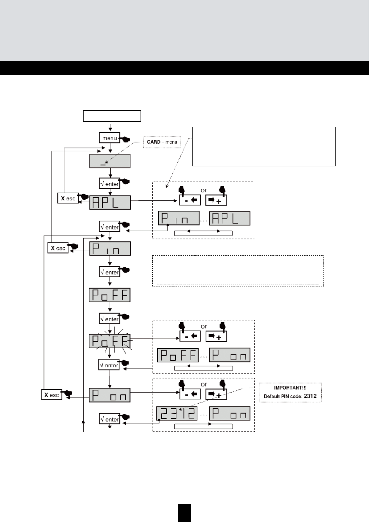
40
TMB Centrales programmables • Notice d’utilisation
TMB 10A • TMB 10B • TMB 10S
FR
CARD Menu
Début
V
oir page suivante
APL
mise à jour du firmware
EHP
mémorisation des données
InP
lecture de fichiers de configuration
PIN
activation et configuration du code PIN
La carte SD/MMC doit être formatée en FAT16.
Les fichiers sont à placer dans le répertoire
racine.
Sélection du sous-menu
Page 41
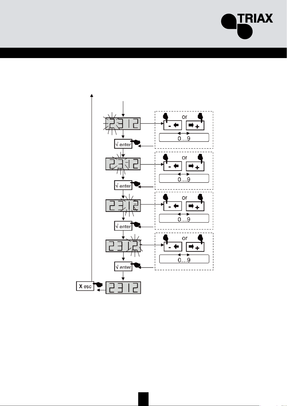
41
FR
Suite de la page précédante
Page 42

42
TMB Centrales programmables • Notice d’utilisation
TMB 10A • TMB 10B • TMB 10S
FR
EHP Export Menu
Début
Insérer la carte SD
Début du processus
lorsque le point clignote
Lorsque l’affichage clignote, le fichier a
déjà été créé sur la carte SD.
En confirmant par « enter », vous
« écrasez » le fichier existant.
Sélection du fichier à lire
Page 43
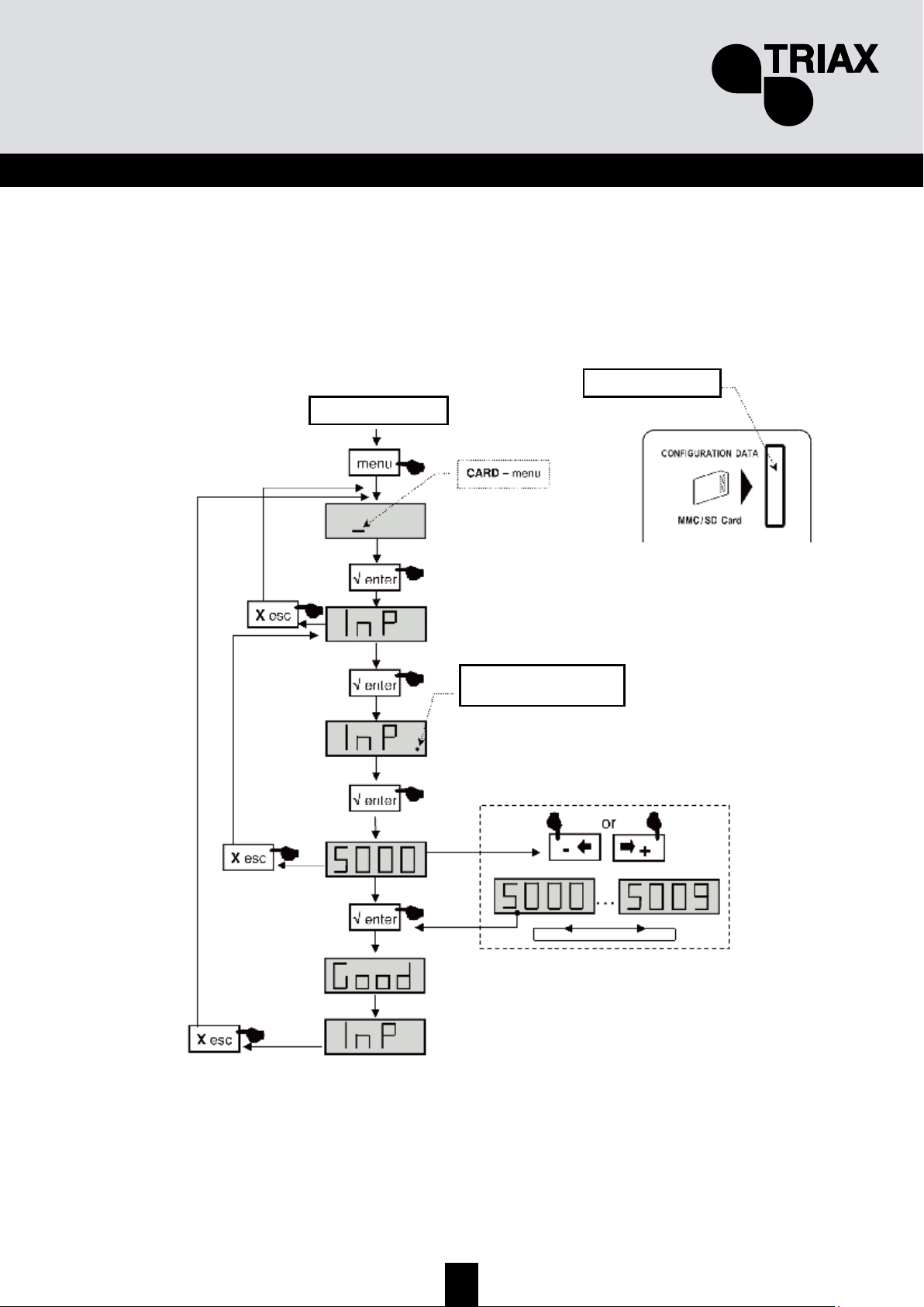
43
FR
InP Import Menu
Début
Insérer la carte SD
Sélection du fichier à lire
Début du processus
lorsque le point clignote
Sélection du fichier à lire
Page 44

44
TMB Centrales programmables • Notice d’utilisation
TMB 10A • TMB 10B • TMB 10S
FR
M
M
M
e
e
e
n
n
n
u
u
u
S
S
S
A
A
A
T
T
T
• Les modules TMB 10S possèdent deux voies d'amplification BIS. Le menu Sat permet de
configurer la tension de téléalimentation des LNB (OFF / 13 /17 V
DC
), d'activer le générateur
22 kHz et l'égaliseur de 12 dB.
Début
menu
'
'
+
0
-
0
ou
'
Sélection de la voie à configurer
SAT – menu
+
0
-
0
ou
√ enter
'
+
0
-
0
ou
Sélection du sous menu
√ enter
'
Afficher la valeur
X esc
'
X esc
'
X esc
'
IL – ajustement du niveau de sortie
Po – alimentation LNB: 0, 13 ou 17V
DC
to – générateur 22kHz on / off
E – égaliseurr on / off,
Page 45

45
FR
C
C
C
a
a
a
r
r
r
a
a
a
c
c
c
t
t
t
é
é
é
r
r
r
i
i
i
s
s
s
t
t
t
i
i
i
q
q
q
u
u
u
e
e
e
s
s
s
t
t
t
e
e
e
c
c
c
h
h
h
n
n
n
i
i
i
q
q
q
u
u
u
e
e
e
s
s
s
Désignation
Référence
Unités
Nombre d'entrées
AMPLIFICATION
Niveau d'entrée max. VHF / UHF /Sat
dBµV
Entrée BI/FM
dB
Entrée BIII
dB
Entrée de couplage VHF-UHF
dB
Entrée UHF 1/2/3
dB
Entrée SAT1 et 2
Préacc. Entrées Sat
Facteur de bruit BIII / UHF / SAT
dB
Atténuateur par entrée
dB
Atténuateur global UHF
dB
Ns VHF/UHF
(IM3 -52dB)
/ SAT
(IM3 -35 dBc)
dBµV
Sortie Test
dB
Niveau de sortie VHF/UHF (IM
2
-60dB)
dBµV
FILTRAGE
Répartition des filtres :
Largeur des voies de filtrage
MHz
Sélectivité des filtres à ± 16 MHz
dB
Adaptation des entrées
dB
Adaptation des sorties
dB
ALIMENTATION
Tension d'alimentation
Consommation sous 230V
VA
Téléalimentation UHF 1, 2 ou 3
V / mA
Entrées équipées
Téléalimentation LNB
V / mA
Générateur 22 kHz
Entrées SAT équipées
Sortie test
dB
Température de fonctionnement
°C
MECANIQUE
Embases entrées/sorties
Dimensions (H x l x P)
mm
0, 13 ou 17 / 300
SAT 1 et 2
ON / OFF
UHF 1, 2 et 3
116 / 120 / 120
8 à 48
12 ou 24 / 55
TMB 10S
324577
8
33
48 / 48 / 48
43
43
80 / 80 / 78
TMB 10 A
324575
TMB 10B
324576
56
55 / 55 / 55 55 / 55 / 55
40
80 / 80 / -
48
48
5 / 9 / -
0 à 20
120 / 122 / - 120 / 122 / -
0 à 20
8 à 48
16
Voir page 7 de ce document
360 x 225 x 50
> 10
> 10
230 VAC
35 35
-5 à +50
12 ou 24 / 55
UHF 1, 2
35
0 à 20
-20 -20 -20
12 (commutable)
43
0 à 20
5 / 9 / 6
-20
-5 à +50
16
> 10
> 10
230 VAC
UHF 1, 2 et 3
-20
"F" femelles
Gabarit de filtre
Page 46

46
TMB Centrales programmables • Notice d’utilisation
TMB 10A • TMB 10B • TMB 10S
FR
entrée sortie Test
BI - BII
47 à 108 MHz
BIII
174 à 240 MHz
VHF-UHF
47 à 862 MHz
Filtre 1
(1 à 6 canaux) 8 à 48 MHz
Filtre 2
(1 à 6 canaux) 8 à 48 MHz
Filtre 3
(1 à 6 canaux) 8 à 48 MHz
Filtre 4
(1 à 6 canaux) 8 à 48 MHz
Filtre 5
(1 à 6 canaux) 8 à 48 MHz
Filtre 6
(1 à 6 canaux) 8 à 48 MHz
Filtre 7
(1 à 6 canaux) 8 à 48 MHz
Filtre 8
(1 à 6 canaux) 8 à 48 MHz
Filtre 9
(1 à 6 canaux) 8 à 48 MHz
Filtre 10
(1 à 6 canaux) 8 à 48 MHz
Niveaux
UHF1
4, 3 ou 1 filtres
UHF2
4, 5, 7 ou 8 filtres
UHF3
2 filtres
Largeur du filtre
Page 47

47
FR
S
S
S
y
y
y
n
n
n
o
o
o
p
p
p
t
t
t
i
i
i
q
q
q
u
u
u
e
e
e
s
s
s
N
N
N
o
o
o
t
t
t
e
e
e
s
s
s
_________________________________________________
_________________________________________________
_________________________________________________
_________________________________________________
_________________________________________________
_________________________________________________
_________________________________________________
_________________________________________________
_________________________________________________
_________________________________________________
_________________________________________________
_________________________________________________
_________________________________________________
_________________________________________________
_________________________________________________
_________________________________________________
_________________________________________________
_________________________________________________
_________________________________________________
Page 48

48
TMB Amplicador Multibanda Programable
TMB 10A • TMB 10B • TMB 10S
ESP
I
I
I
n
n
n
s
s
s
t
t
t
r
r
r
u
u
u
c
c
c
c
c
c
i
i
i
o
o
o
n
n
n
e
e
e
s
s
s
d
d
d
e
e
e
s
s
s
e
e
e
g
g
g
u
u
u
r
r
r
i
i
i
d
d
d
a
a
a
d
d
d
Importante: La central solo puede ser abierta por personal autorizado o cualificado.
• Desconectar la central de la toma de tensión antes de quitar las tapas (riesgo de electrocución).
• Para mantener la temperatura del aparato dentro de su rango normal de operación, asegurar la
circulación libre de aire alrededor del aparato (evita colocarlo en espacios cerrados). Las rejillas
ventilación deben de estar libres de cualquier obstrucción.
• Asegurarse que ningún líquido puedan penetrar dentro de la unidad (salpicaduras y/o fugas).
• No instalar la central en un lugar húmedo. Si hay condensación en la unidad, no utilizar hasta que
se haya secado completamente.
• El cable de energía eléctrica y los cables de conexión de RF deben de estar en buen estado (ni
aplastados ni obstruidos).
• El enchufe de red debe de estar fácilmente accesible para el técnico y protegido o fuera del
alcance de niños.
Toma de tierra
• La instalación debe de cumplir los requisitos especificados de la norma Europea EN 50083
(conformidad de instalaciones colectivas) y EN 60065 (los estándares vigentes para la protección
eléctrica).
Reemplazar fusibles
• Solo un técnico cualificado puede reemplazar los fusibles
Compatibilidad electromagnética (EMC)
• Asegúrese de que los tornillos estén convenientemente apretados.
• Los cables y terminales de conexión no deben mostrar signos de oxidación.
Page 49
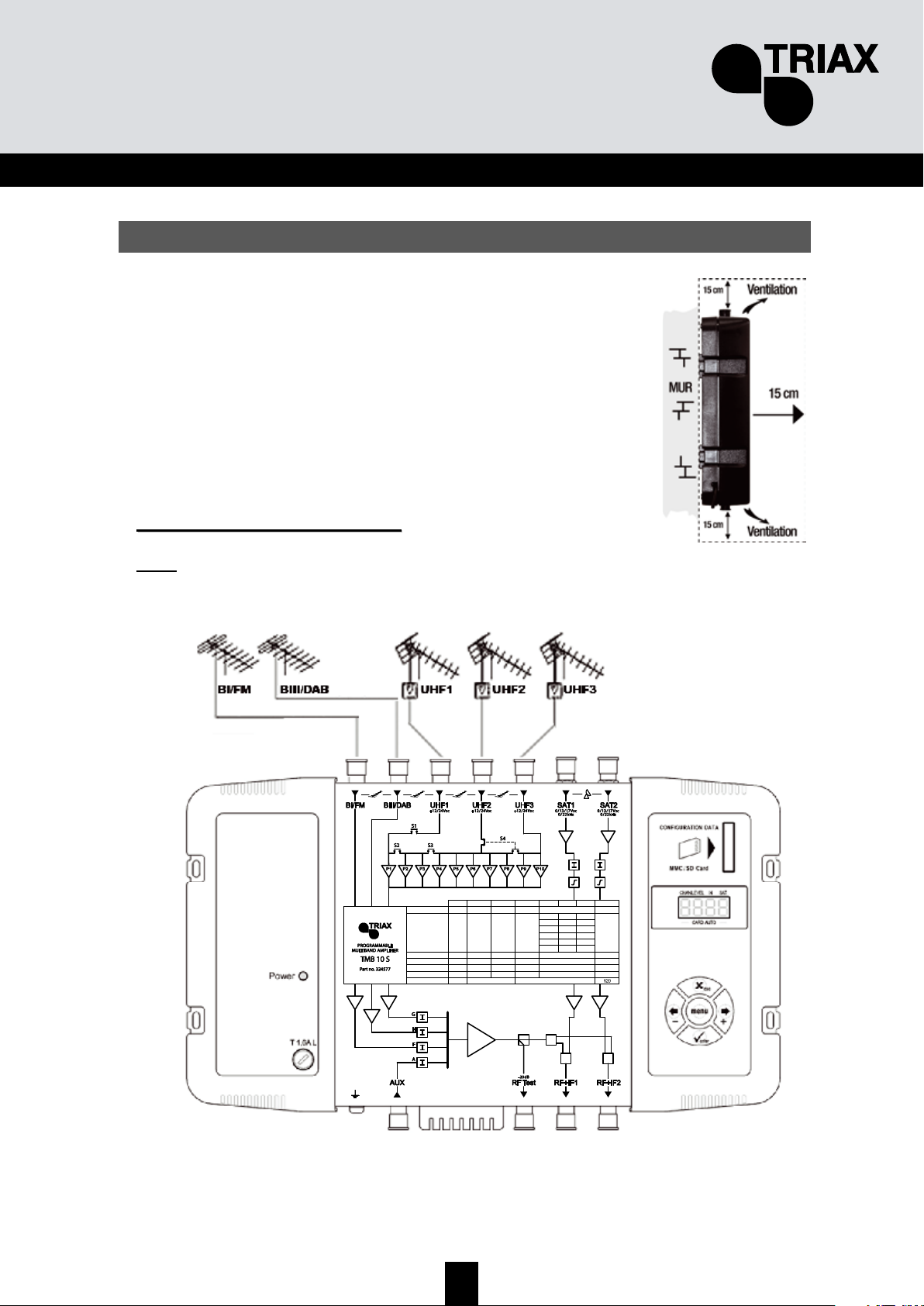
49
ESP
I
I
I
n
n
n
s
s
s
t
t
t
a
a
a
l
l
l
a
a
a
l
l
l
a
a
a
c
c
c
i
i
i
ó
ó
ó
n
n
n
d
d
d
e
e
e
l
l
l
a
a
a
c
c
c
e
e
e
n
n
n
t
t
t
r
r
r
a
a
a
l
l
l
Se recomienda que se instale la central en un lugar suficientemente
ventilado. La ventilación natural debe poder circular por las ranuras de la
ventilación; deje un espacio mínimo de 15 cm alrededor de la central
para asegurar la máxima ventilación.
Al instalar o cablear la central, se recomienda que se desconecte el
cable de energía eléctrica.
CCoonneexxiióónn ddee llaa cceennttrraall
Nota:
Las entradas de UHF pueden suministrar tensión remotamente y están protegidas contra
cortocircuitos. La tensión disponible es 12 o 24V, max. 50mA. El preamplificador es detectado
automáticamente y sólo hay que programar la tensión de alimentación.
Max. Output level*
Max. Input level
Noise
Attenuator
Gain (typical)
UHF lter setting
Frequency range MHz
Unit
dBµV
dBµV
dB
dB
dB
47÷108
BI-FM
116
80
5
0…20
43
/
174÷230
BIII-DAB
80
5
0…20
43
/
47÷862
AUX
80
10
0…20
33
/
UHF1
120
–
1
3
–
1
3
470÷862
UHF2
80
9
0…20
48
–
–
–
8
7
5
UHF3
10
9
7
2
2
2
950÷2150
SAT
79
6
0…20
40
/
*DIN 45004B
Page 50
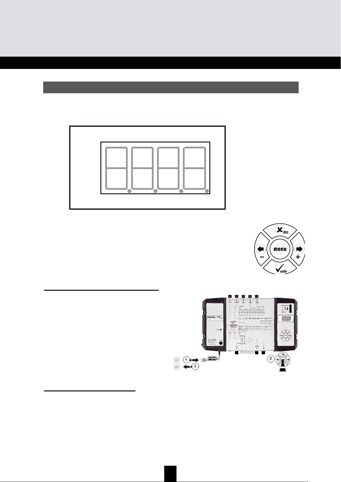
50
TMB Amplicador Multibanda Programable
TMB 10A • TMB 10B • TMB 10S
ESP
P
P
P
r
r
r
o
o
o
g
g
g
r
r
r
a
a
a
m
m
m
a
a
a
c
c
c
i
i
i
ó
ó
ó
n
n
n
Un display de 4 dígitos y un teclado numérico es todo lo que se necesita para programar la central.
Siga los pasos de abajo indicados para configurar los diferentes parámetros
Cuándo la central esta conectada:
• El modo de programa esta en standby (en espera).
• Por defecto, el sistema viene configurado como:
o UHF1 Î 3 UHF filtros
o UHF2 Î 0 UHF filtros
o UHF3 Î 7 UHF filtros
• Todos los filtros de UHF estan desactivados (display "
- -"),
• Los atenuadores estan a cero.
VVaalloorreess ddee ffaabbrriiccaa.. RREESSEETT
Cuando sea necesario restablecer los valores de fábrica:
1. Desconectar el cable de alimentación de red
2. Mantener pulsada la tecla
esc
3. Conectar el cable de alimentación de red
Todos los parámetros programados son eliminados
y la central pasa a modo de programa en stanby (en espera)
• Soltar la tecla
esc cuando se muestre
en el display “8888”
FFeecchhaa ddee ffaabbrriiccaacciióónn
Si es necesario consultar la fecha de fabricación y la versión de la central, pulsar las teclas
- & +.
A los 2 segundos, la central muestra en el display la fecha de fabrica en el formato; A-SS donde
A
indica el último digito del año y
SS la semana de fabricación
Digit 1 Digit 2
Di
g
it 3
Di
g
it 4
CHAN LEVEL IN SAT
____ AUTO CARD ____
Page 51

51
ESP
CCoonnffiigguurraacciióónn
Al conectar la central a la red, esta pasa a modo standby (en espera), un segmento luminoso se
desplaza a través del display.
O
O
O
p
p
p
e
e
e
r
r
r
a
a
a
c
c
c
i
i
i
o
o
o
n
n
n
e
e
e
s
s
s
p
p
p
r
r
r
i
i
i
n
n
n
c
c
c
i
i
i
p
p
p
a
a
a
l
l
l
e
e
e
s
s
s
Para acceder a los menús de configuración, pulse la tecla menú hasta que el segmento luminoso
se posicione debajo del menú a configurar y pulse la tecla enter.
Resumen:
• Para desplazarse por los menús, use la tecla menú.
• Para entrar en el menú, pulse enter.
• Para salir del menú, presione la tecla menú.
Note:
Si durante 1 minuto no se pulsa ninguna tecla, la central cambia a modo standby (en espera).
M
M
M
e
e
e
n
n
n
ú
ú
ú
s
s
s
CHAN
Configuración de los filtros UHF:
• Canal
• Ancho de Banda (1 a 6 canales; 8 a 48 MHz)
LEVEL
Configuración de los atenuadores.
IN
Configuración de la distribución de los filtros a las entradas UHF1, 2 y 3.
Selección de la tensión de alimentación remota (12 or 24 V
DC
).
AUTO
Uso del CAG (Control Automático de Ganancia).
Alineación automática del los canales de UHF.
CARD
Leer y guardar configuraciones
Activación y configuración del código PIN.
SAT
Configuración de los atenuadores de FI.
Ecualización fija de 0 dB (OFF) ó 12 dB (ON)
Selección de tensión remota a los LNBs (0, 13 or 17 V
DC
).
Selección 0 - 22 kHz (ON/OFF).
Page 52
52
TMB Amplicador Multibanda Programable
TMB 10A • TMB 10B • TMB 10S
ESP
C
C
C
H
H
H
A
A
A
N
N
N
M
M
M
e
e
e
n
n
n
u
u
u
Las centrales TMB tienen 6 o 10 filtros UHF configurables. Los filtros UHF pueden distribuirse a las
3 entradas UHF1, UHF2, UHF3 como se muestra a continuación:
TMB 10A
Entrada UHF1 UHF2 UHF3
423315-
-6-
Número de filtros por
entrada UHF
TMB 10B & S
Entrada UHF1 UHF2 UHF3
352
172
-82
3-7
1-9
- - 10
Número de filtros por
entrada UHF
El ancho de banda de cada filtro puede ser configurado de 8 a 48 MHz (1 a 6 canales).
D
D
D
i
i
i
s
s
s
t
t
t
r
r
r
i
i
i
b
b
b
u
u
u
c
c
c
i
i
i
ó
ó
ó
n
n
n
d
d
d
e
e
e
l
l
l
o
o
o
s
s
s
f
f
f
i
i
i
l
l
l
t
t
t
r
r
r
o
o
o
s
s
s
U
U
U
H
H
H
F
F
F
Ir al menú IN, cuando el segmento luminoso este debajo de la marca IN pulse enter.
• Pulse enter otra vez para cambiar la configuración de las entradas UHF (display
intermitente)
• Pulse las teclas + o – para seleccionar la distribución de los filtros a las entradas UHF.
Notas:
Cada filtro UHF puede ser desactivado. Solo configure los filtros necesarios a los canales
requeridos en el menú "CHAN".
Page 53

53
ESP
Start
menu
'
'
+
0
-
0
or
'
Selección del sub-menu
IN – input menu
U – Selección de los filtros a las
entradas UHF1, UHF2 y UHF3
Po – Selección de la tensión de
salida: 12V DC o 24V DC para
amplificadores de mástil
'
X esc
'
+
0
-
0
o
Selección de la distribución de los filtros UHF
'
+
0
-
0
o
Alimentación remota
X
esc
/
Este menú es utilizado para seleccionar el valor de
la tensión remota en las entradas UHF 1, 2 y 3. La
unidad reconoce automáticamente el amplificador
conectado y cambia la alimentación remota a ON.
Distribución de los filtros UHF
352
172
082
307
109
001
Quite el cable de red antes de
cualquier trabajo de cableado
Page 54
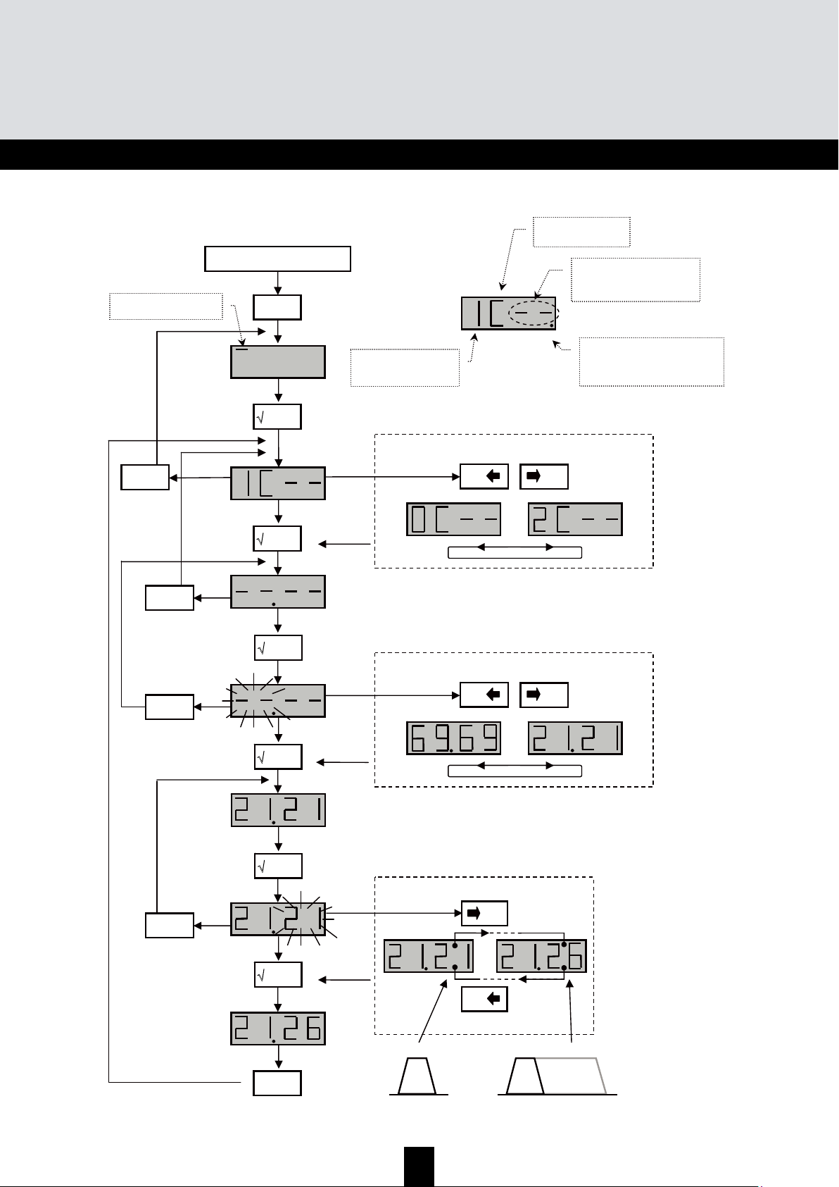
54
TMB Amplicador Multibanda Programable
TMB 10A • TMB 10B • TMB 10S
ESP
A
A
A
n
n
n
c
c
c
h
h
h
o
o
o
d
d
d
e
e
e
b
b
b
a
a
a
n
n
n
d
d
d
a
a
a
U
U
U
H
H
H
F
F
F
(
(
(
C
C
C
H
H
H
A
A
A
N
N
N
m
m
m
e
e
e
n
n
n
u
u
u
)
)
)
26
21
Start
menu
'
'
X esc
'
+
0
-
0
or
'
'
'
'
'
X esc
/
X esc
/
X esc
/
X esc
/
Seleccione el filtro a configurar
+
0
-
0
or
Seleccione el canal de inicio
Seleccione el canal final
+
0
-
/
21
1 canal max. 6 canales
CHAN – menu
Número del canal de inicio.
Si el cluster no es usado, el
display muestra “--“.
Filtro número 1 a 10
(0 para el filtro no. 10)
El punto del display se enciende y
se apaga cuando el filtro tiene un
ancho > 1 canal.
C – menú Canal
Page 55
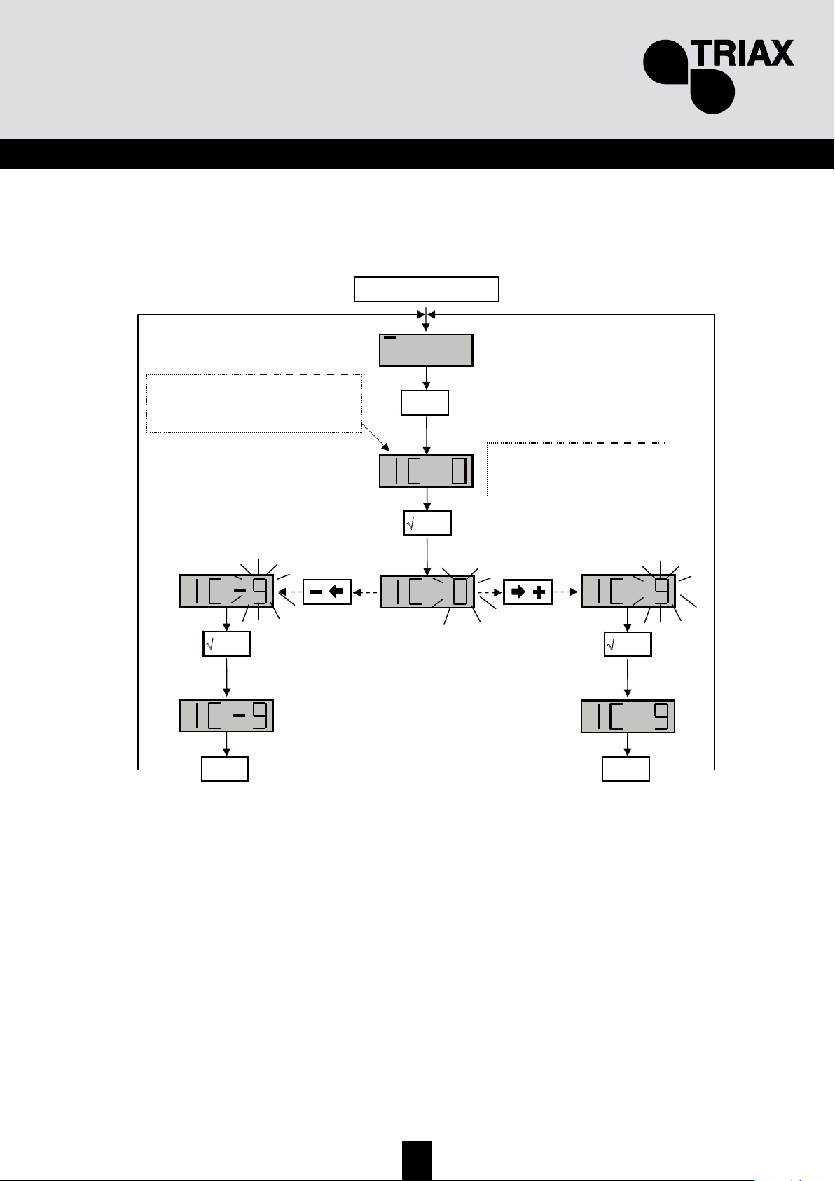
55
ESP
S
S
S
i
i
i
n
n
n
t
t
t
o
o
o
n
n
n
i
i
i
z
z
z
a
a
a
c
c
c
i
i
i
ó
ó
ó
n
n
n
f
f
f
i
i
i
n
n
n
a
a
a
Esta función es utilizada para compensar la frecuencia del filtro afectado, y ajustar los filtros según
las características de las señales recibidas (desviación, canales adyacentes, etc.).
Compruebe la desviación en su aparato de la medida.
Start
'
X
esc
'
0
0
La función solo actúa sobre
el filtro seleccionado
Seleccione el filtro usando
las teclas + and –
'
'
X esc
'
X esc
'
Page 56
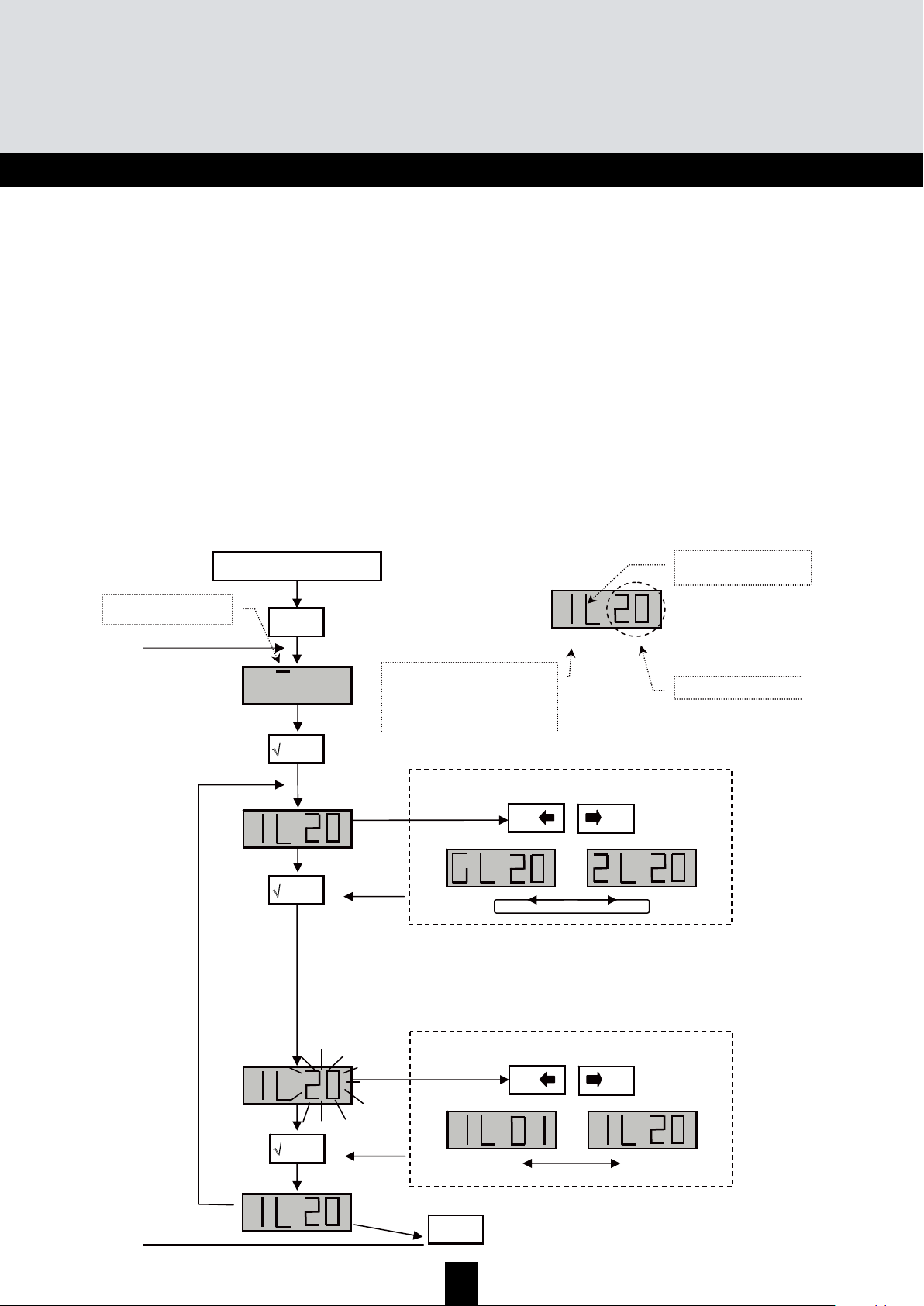
56
TMB Amplicador Multibanda Programable
TMB 10A • TMB 10B • TMB 10S
ESP
Configuración de niveles.
Hay tres tipos de configuración de niveles:
• “Manual” configuración de niveles de salida (LEVEL menú)
• Ajuste automático del nivel de salida de los filtros UHF a un valor fijado por el usuario
(menú de Auto, sub-menú LEU).
• Control automático de ganancia UHF (menú Auto, sub-menu AGC)
C
C
C
o
o
o
n
n
n
f
f
f
i
i
i
g
g
g
u
u
u
r
r
r
a
a
a
c
c
c
i
i
i
ó
ó
ó
n
n
n
d
d
d
e
e
e
l
l
l
o
o
o
s
s
s
a
a
a
t
t
t
e
e
e
n
n
n
u
u
u
a
a
a
d
d
d
o
o
o
r
r
r
e
e
e
s
s
s
(
(
(
L
L
L
E
E
E
V
V
V
E
E
E
L
L
L
m
m
m
e
e
e
n
n
n
ú
ú
ú
)
)
)
Ir al menú LEVEL, cuando el segmento luminoso este debajo de la marca LEVEL pulse enter.
• Pulse las tecla + o - para seleccionar el canal a ajustar.
•
Confirme pulsando la tecla enter
• Cuando el display se pone en intermitente (destellos), se puede ajustar la atenuación (20
indica atenuación 0; 1 indica max atenuación)
• Para confirmar pulse enter
X
esc
'
Start
menu
'
'
+
0
-
0
o
'
Selección sub-menu
L – menu level
Atenuación -1 a -20 dB
L – menú LEVEL
1…0 – filtro número, de 1 a 10
H – banda VHF (BIII)
F – banda FM (BI/FM)
A – entrada auxiliary (AUX)
G – Ganancia UHF
+
0
-
0
or
Seleccione la atenuación
'
Page 57
57
ESP
M
M
M
e
e
e
n
n
n
ú
ú
ú
c
c
c
o
o
o
n
n
n
t
t
t
r
r
r
o
o
o
l
l
l
a
a
a
u
u
u
t
t
t
o
o
o
m
m
m
á
á
á
t
t
t
i
i
i
c
c
c
o
o
o
d
d
d
e
e
e
g
g
g
a
a
a
n
n
n
a
a
a
n
n
n
c
c
c
i
i
i
a
a
a
.
.
.
G
G
G
A
A
A
C
C
C
Nota: el ajuste de los niveles de BI-II / BIII / AUX no son automáticos.
Cuando se activa el GAC (CAG) el nivel de salida de RF de las señales UHF son almacenadas en
la memoria. Si el nivel medido de la señal cambia de ± 1 dB el CAG comienza actuar. Los cambios
en la señal pueden ser causados por cualquier señal de cualquier entrada UHF1 – UHF2 – UHF3.
Cuando el CAG comienza actuar, el microcontrolador establece el valor apropiado en el atenuador
G, dentro de su grado de regulación. El CAG deja de actuar cuando la señal medida es la misma
que la almacenada en su memoria o cuando alcanza el valor máximo o mínimo del atenuador G
(dentro de su rango).
¾ Atenuador G en posición 20 y GAG en ON, la regulación podrá corregir una variación máxima
del nivel de entrada de +20 dB
¾ Atenuador G en posición 10 y GAG en ON, la regulación podrá corregir una variación máxima
del nivel de entrada de ±10 dB
¾ Atenuador G en posición 0 y GAG en ON, la regulación podrá corregir una variación máxima
del nivel de entrada de -20 dB
NOTA:
E nivel máximo de salida del amplificador depende del número de canales utilizados. Utilizar la
tabla de abajo para determinara el coeficiente de reducción.
Nº de
Canales
2 3 4 5 6 7 8 9 10 11 12 13 14 15 16 17 18
Coef.
Reducción
0,0 2,5 3 4,5 5,0 5,5 6 6,5 7 7,5 8,0 8,0 8,5 8,5 9,0 9,0 9,5
Nivel máximo salida amplificador = 120 dBµV (DIN 45004B), 10 Canales amplificados Ns= 120 – 7 =
113 dBµV
Ejemplo 1
Amplificación de 10 Canales (Nivel de entrada 70 dBµV)
Nivel máximo de salida para los 10 canales UHF: 120 – 7 = 113 dBµV
• Nivel de salida necesario para la instalación: 110 dBµV
• 70 + 50 dB de ganancia = 120 dBµV
• Para obtener los 110 dBµV requeridos tenemos que actuando sobre el atenuador general
G en 10 dB
- Si activamos el CAG el nivel de salida de 110 dBµV se mantendrá fijo para variaciones de
las señales de entrada entre + 10 a -10 dB.
Ejemplo 2
Amplificación de 10 Canales (Nivel de entrada 75 dBµV)
Nivel máximo de salida para los 10 canales UHF: 120 – 7 = 113 dBµV
• Nivel de salida necesario para la instalación: 110 dBµV
• 75 + 50 dB de ganancia = 125 dBµV
• Para obtener los 110 dBµV requeridos tenemos que actuando sobre el atenuador general
G en 15 dB
- Si activamos el CAG el nivel de salida de 110 dBµV se mantendrá fijo para variaciones de
las señales de entrada entre + 5 a -15 dB.
Page 58

58
TMB Amplicador Multibanda Programable
TMB 10A • TMB 10B • TMB 10S
ESP
Start
menu
'
'
'
AUTO – menu
√ enter
'
+
0
-
0
o
√ enter
'
Valor del nivel de salida en el display
X
esc
'
X esc
'
min. max.
+
0
-
0
o
Selección sub-menu
'
'
+
0
-
0
o
'
X esc
'
X esc
'
IMPORTANTE!
La unidad memoriza el nivel medio de salida. Si el
nivel medido de la señal cambia de ± 1 dB el CAG
comienza actuar y compensa la variación de la
ganancia dentro de los límites.
Cuando AGC esta en ON, en el menú principal no
están disponible el resto de menús. Para modificar los
parámetros, cambiar el modo función AGC a OFF.
Page 59
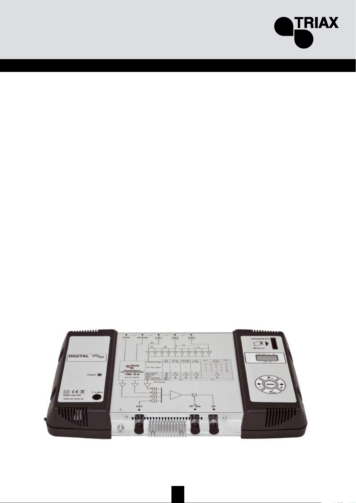
59
ESP
M
M
M
e
e
e
n
n
n
u
u
u
C
C
C
A
A
A
R
R
R
D
D
D
Las centrales TMB tienen un interface SD/MMC para guardar o cargar configuraciones y
actualizaciones del producto.
Este menú incluye 4 sub-menus:
• APL actualización del firmware
Cuando la tarjeta contienen el archivo de actualización (tm_tmb10.tlp), y la tecla enter es pulsada la
actualización comienza automáticamente y en el display se puede ver “Boot”.
• EHP Memorización de datos
Seleccione el sub-menú y escoja un nombre de fichero. El display destella cuando el archivo ya
existe. Pulsando la tecla enter los datos son guardados.
• InP cargar configuraciones
Seleccione el sub-menú y escoja un nombre de fichero a cargar. Pulsar la tecla enter y la carga
comienza; cuando la carga es completa el display muestra "Good".
• PIN activación y configuración del código PIN
Cuando la función esta activada, el código PIN es requerido para acceder a los menús (introduzca
el código PIN usando el teclado y confirme pulsando enter). Si durante 30 segundos no se pulsa
ninguna tecla, la central cambia a modo standby (en espera) y el código PIN debe ser introducido
otra vez para acceder a los menús.
Importante.
• Cuando la tarjeta SD no esta insertada y los menús APL, EHP o InP son activados, en el
display se muestra “Err”.
• La tarjeta S/MMC debe ser formateada en FAT16. Los archivos deben ser colocados en el
directorio raíz.
• Los archivos de configuración son nombrados y específicamente según el modelo (S00x
para TMB10S, B00x para TMB10B, A00x para TMB10A).
• Por defecto el código PIN es 2312.
Page 60

60
TMB Amplicador Multibanda Programable
TMB 10A • TMB 10B • TMB 10S
ESP
CARD Menu
Continua en la pagina siguiente
La tarjeta SD/MMC debe de formartearse en FAT 16.
Los archivos deben de colocarse en el directorio raiz.
Si la tarjeta SD/MMC no contiene archivos el display
mostrará durante el reinicio noFL
-
Inicio Programación
menu
'
'
'
CARD – menu
X
esc
'
+
0
-
0
or
Seleción submenu
APL – Actualización firmware
EHP – Memorización de datos
InP – Carga de configuraciones
PIN – Activación y configuración del código
'
'
+
0
-
0
or
'
X
esc
'
+
0
-
0
or
'
X
esc
'
IMPORTANTE!!!
Por defecto PIN code: 2312
Page 61

61
ESP
EHP Export Menu
Continuación de la pagina anterio
r
Page 62

62
TMB Amplicador Multibanda Programable
TMB 10A • TMB 10B • TMB 10S
ESP
EHP Menú Export
Start
menu
'
'
'
CARD – menu
X
esc
'
'
X
esc
'
+
0
-
0
or
X
esc
'
Introducir la tarjeta
SD/MMC en el slot
IMPORTANTE!
Cuando el número parpadea, indica
que el archivo ya existe en la tarjeta
MMC / SD. Pulsando la tecla ENTER,
el archivo existente será reemplazado
Seleccione el número de archivo
'
Page 63

63
ESP
InP Menú Importar
Start
menu
'
'
'
CARD – menu
X
esc
'
'
X
esc
'
+
0
-
0
or
X
esc
'
Introducir la tarjeta
SD/MMC en el slot
'
Cuando el PUNTO esta
iluminado, indica que el
proceso esta en marcha
Page 64
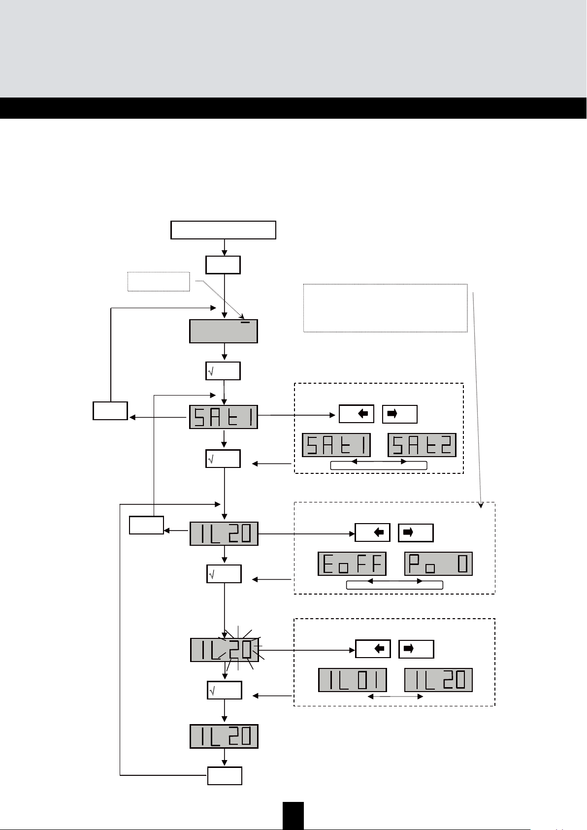
64
TMB Amplicador Multibanda Programable
TMB 10A • TMB 10B • TMB 10S
ESP
M
M
M
e
e
e
n
n
n
ú
ú
ú
S
S
S
A
A
A
T
T
T
• Los modelos TMB 10 S tienen dos circuitos de amplificación FI. En el menú Sat se puede
configurar la alimentación remota del LNB (OFF/13 /17 VDC), activar el generador de 22
khz y el ecualizador de 12 dB.
Start
menu
'
'
+
0
-
0
or
'
Seleccione el circuito SAT a configurar
SAT – menu
+
0
-
0
or
√ enter
'
+
0
-
0
or
Select the sub-menu
√ enter
'
Valor en Display
X esc
'
X esc
'
X esc
'
IL – ajuste del nivel de salida
Po – alimentación LNB: 0, 13 or 17V
DC
to – generador 22kHz on / off
E – ecualizador on / off,
Page 65
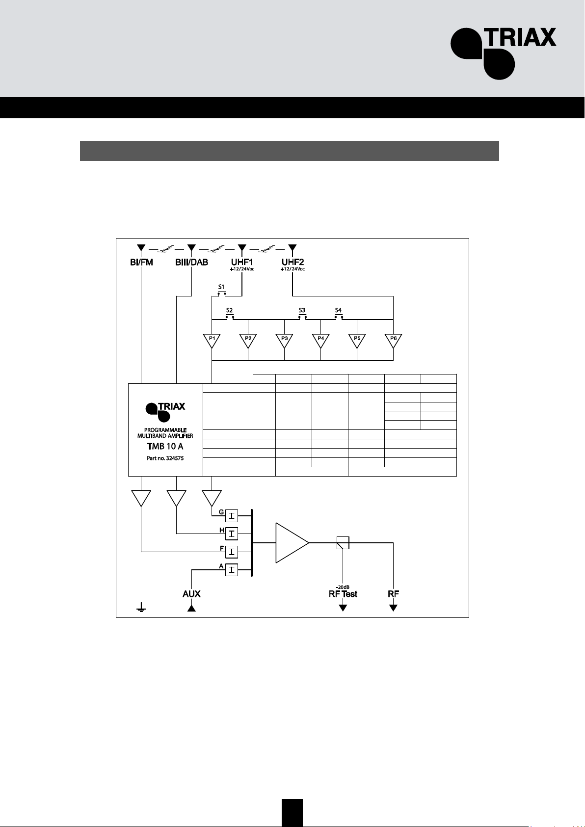
65
ESP
D
D
D
i
i
i
a
a
a
g
g
g
r
r
r
a
a
a
m
m
m
s
s
s
Diagrama TMB-10A
Max. Output level*
Max. Input level
Noise
Attenuator
Gain (typical)
UHF filter setting
Frequency range MHz
Unit
dBµV
dBµV
dB
dB
dB
47÷108
BI-FM
122
80
5
0…20
48
/
174÷230
BIII-DAB
80
5
0…20
48
/
47÷862
AUX
80
10
0…20
39
/
124
80
9
0…20
55
UHF1
1
4
470÷862
UHF2
5
3
2
3
–6
*DIN 45004B
Page 66
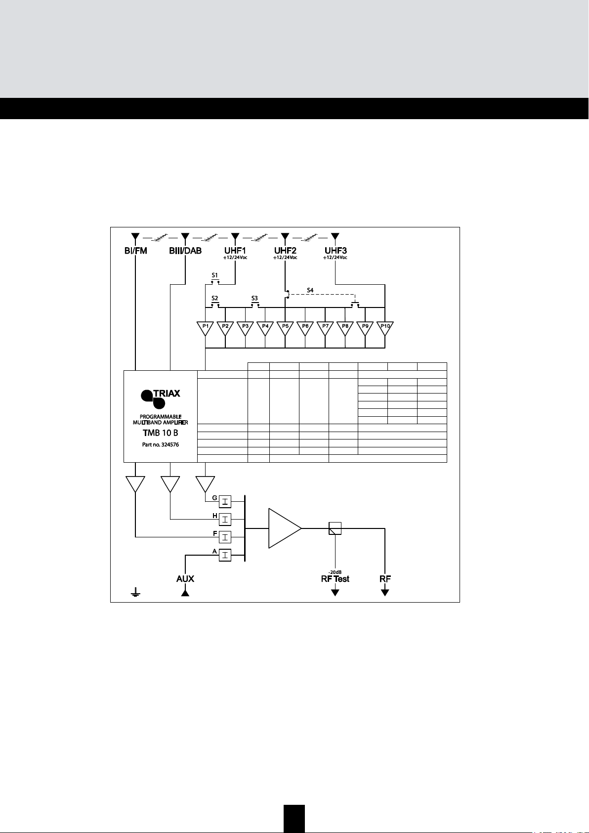
66
TMB Amplicador Multibanda Programable
TMB 10A • TMB 10B • TMB 10S
ESP
Diagrama TMB-10B
Max. Output level*
Max. Input level
Noise
Attenuator
Gain (typical)
UHF filter setting
Frequency range MHz
Unit
dBµV
dBµV
dB
dB
dB
47÷108
BI-FM
122
80
5
0…20
48
/
174÷230
BIII-DAB
80
5
0…20
48
/
47÷862
AUX
80
10
0…20
39
/
UHF1
124
–
1
3
–
1
3
470÷862
UHF2
80
9
0…20
55
–
–
–
8
7
5
UHF3
10
9
7
2
2
2
*DIN 45004B
Page 67
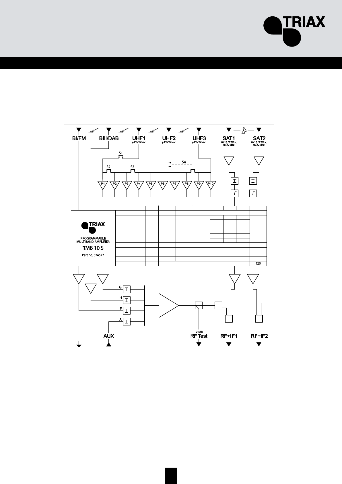
67
ESP
Diagrama TMB-10S
Max. Output level*
Max. Input level
Noise
Attenuator
Gain (typical)
UHF filter setting
Frequency range MHz
Unit
dBµV
dBµV
dB
dB
dB
47÷108
BI-FM
116
80
5
0…20
43
/
174÷230
BIII-DAB
80
5
0…20
43
/
47÷862
AUX
80
10
0…20
33
/
UHF1
120
–
1
3
–
1
3
470÷862
UHF2
80
9
0…20
48
–
–
–
8
7
5
UHF3
10
9
7
2
2
2
950÷2150
SAT
79
6
0…20
40
/
*DIN 45004B
Page 68
68
TMB Amplicador Multibanda Programable
TMB 10A • TMB 10B • TMB 10S
ESP
E
E
E
s
s
s
p
p
p
e
e
e
c
c
c
i
i
i
f
f
f
i
i
i
c
c
c
a
a
a
c
c
c
i
i
i
o
o
o
n
n
n
e
e
e
s
s
s
t
t
t
é
é
é
c
c
c
n
n
n
i
i
i
c
c
c
a
a
a
s
s
s
Artículo TMB-10A TMB-10B TMB-10S
Referencia / part number
Units
324575 324576 324577
Número de entradas
5 6 8
AMPLIFICACION
Max. Nivel de entrada VHF/UHF
dB 80/80
Ganancia entrada BI/FM
dB 48 43
Ganancia entrada BIII/DAB
dB 48 43
Ganancia entrada AUX
dB 39 33
Ecualización entrada VHF/UHF
dB 5
Ganancia entradas UHF 1/2/3
dB 55 / 55 /- 55 / 55 / 55 48 / 48 / 48
Ganancia entrada SAT 1 y SAT
dB 40
Ecualización entradas SAT
dB 9 (switchable)
Factor de ruido BIII / UHF / SAT
dB 5 / 9 / - 5 / 9 / 6
Atenuación por entrada
dB 0 to 20
Atenuación Global salida UHF
dB 0 to 20
Regulación CAG salida UHF
dB -9 to +10
Max. Nivel salida VHF / UHF/ SAT
(DIN45004B)
dBµV 122 / 124 / - 116 / 120 / 120
Punto test de salida
dB -20
FILTROS
Distribución de filtros
Ver pag. 7 del
manual
Ancho de banda de los filtros
MHz 8 to 48
Selectividad de filtros a +/- 16MHz
dB 16
Adaptación de entradas
dB >10
Adaptación de salidas
dB >10
FUENTE DE ALIMENTACIÓN
Voltaje
VAC 230
Consumo a 230VAC
VA 35
Alimentación remota UHF1,2 or 3
VDC/mA 12 or 24 /55
Entradas equipadas
UHF 1 y 2 UHF 1, 2 y 3
Alimentación LNB
VDC/mA 0,13 or 17 /300
Generador 22kHz
ON / OFF
Entradas SAT equipadas
SAT 1 y 2
Test de salida
dB -20
Rango de temperatura
ºC -5 to +50
MECANICA
Conectores entradas/salida
"F" female
Dimensiones (H x W x D)
mm 225 x 360 x 50
Filter data.
Page 69
69
ESP
TMB Programmable Multiband Amplifier
E n tr a d a S a li d a T e s t
B I - B II 4 7 a 1 0 8 M H z
B II I 1 7 4 a 2 4 0 M H z
V H F -U H F
4 7 a 2 4 0
& 4 7 0 a 8 6 2 M H z
F ilt r o 1
( 1 t o 6 c a n a le s ) 8 t o 4 8
M H z
F ilt r o 2
( 1 a 6 c a n a l e s ) 8 a 4 8 M H z
F ilt r o 3
( 1 a 6 c a n a l e s ) 8 a 4 8 M H z
F ilt r o 4
( 1 a 6 c a n a l e s ) 8 a 4 8 M H z
F ilt r o 5
( 1 a 6 c a n a l e s ) 8 a 4 8 M H z
F ilt r o 6
( 1 a 6 c a n a l e s ) 8 a 4 8 M H z
F ilt r o 7
( 1 a 6 c a n a l e s ) 8 a 4 8 M H z
F ilt r o 8
( 1 a 6 c a n a l e s ) 8 a 4 8 M H z
F ilt r o 9
( 1 a 6 c a n a l e s ) 8 a 4 8 M H z
F ilt r o 1 0
( 1 a 6 c a n a l e s ) 8 to 4 8 M H z
N iv e le s
U H F 1
1 o 3 f i lt ro s
U H F 2
5 , 7 o 8 f il tr o s
U H F 3 2 ,
7 , 9 o 1 0 fi lt ro s
A n c h o d e l F i l tr o
Page 70
70
TMB Programmable Multiband Amplier
TMB 10A • TMB 10B • TMB 10S
SE
1. Kom-igång guide TMB
Start
1
2
Packa upp innehållet
Läs bruksanvisningen
3
Montera TMB förstärkaren på vägg
4
Anslut antennsignal på respektive ingång
5
Programmera TMB förstärkaren
6
Anslut mätinstrument på utgången
7
Justera nivåerna på respektive filter
8
Aktivera PIN kod om så önskas
Start
Page 71

71
SE
2. Innehåll
1. Kom-igång guide TMB......................................................................................... 2
2. Innehåll................................................................................................................ 3
3. Säkerhetsföreskrifter ........................................................................................... 4
4. Anslutningar ........................................................................................................ 5
5. Menyer ................................................................................................................ 6
Huvudmeny ......................................................................................................... 6
LED Display......................................................................................................... 6
Programmeringsknappar ..................................................................................... 6
6. Start programmering............................................................................................ 7
6.1 CHAN (kanal) meny....................................................................................... 7
6.2 LEVEL (nivå) meny........................................................................................ 8
6.3 IN (inkanal) meny .......................................................................................... 9
6.4 SAT meny.................................................................................................... 10
6.5 AUTO meny................................................................................................. 11
6.6 CARD (kort) meny ....................................................................................... 12
6.6.1 EHP (Exportering meny)........................................................................... 14
6.6.2 InP (Importering meny)............................................................................. 15
7. ÅTERSTÄLL till fabriksinställningar ................................................................... 15
8. Extra funktioner ................................................................................................. 16
8.1 Mjukvaru version ......................................................................................... 16
8.2 Fin inställning .............................................................................................. 16
9. Tekniska specifikationer .................................................................................... 17
Page 72
72
TMB Programmable Multiband Amplier
TMB 10A • TMB 10B • TMB 10S
SE
3. Säkerhetsföreskrifter
Varning. Endast auktoriserade får öppna enheten. Avlägsna strömdelen innan locket öppnas.
Omgivningstemperaturen får ej överstiga +50 grader.
VARNING
Driftstemperatur Ventilation
Fuktighet
max. 80%
I enlighet med EN 50083 ska jordning utföras.
Jordning
Page 73
73
SE
4. Anslutningar
LED display –
4 siffror
Programmerings-
knappar
Plats för
MMC / SD kort
2 x LNB
ingångar
Antenningångar
Säkring / T 1,6A
Strömindikator –
LED diod
Jordningsanslutning
AUX ingång
Test uttag / -20dB
Utgångar
Monterings-
hål
Max. Output level*
Max. Input level
Noise
Attenuator
Gain (typical)
UHF lter setting
Frequency range MHz
Unit
dBµV
dBµV
dB
dB
dB
47÷108
BI-FM
116
80
5
0…20
43
/
174÷230
BIII-DAB
80
5
0…20
43
/
47÷862
AUX
80
10
0…20
33
/
UHF1
120
–
1
3
–
1
3
470÷862
UHF2
80
9
0…20
48
–
–
–
8
7
5
UHF3
10
9
7
2
2
2
950÷2150
SAT
79
6
0…20
40
/
*DIN 45004B
Page 74

74
TMB Programmable Multiband Amplier
TMB 10A • TMB 10B • TMB 10S
SE
5. Menyer
Huvudmeny
Huvudmenyn ger åtkomst till sex undermenyer på förstärkaren, (Kanal, Nivå, Ingång, SAT,
Kort, Auto). För att välja rätt undermeny, tryck på MENU knappen. En röd liggande diod flyttar
sig och markerar den aktuella undermenyn. Tryck på ENTER knappen när dioden står på den
plats åtkomst önskas.
Vid normalläge: parametervärdet lyser oavbrutet, avläsning av inprogrammerad värde,
parametervärdet blinkar, värdet kan ändras. För att komma ur, när det blinker tryck på ENTER
knappen för att spara inställningen, eller ESC knappen för att lämna menyn utan att spara
ändringar.
LED Display
Programmeringsknappar
1 2
3
4
CHAN LEVEL IN
SAT
____ AUTO CARD ____
Avbryt
men
y
Ändra
värden „+”
Ändra
värden „-”
Meny val eller återgå
till
HUVUDMENY
Acceptera
meny, värden
KANAL meny
NIVÅ meny
SAT meny
INGÅNG meny
KORT meny AUTO meny
Page 75
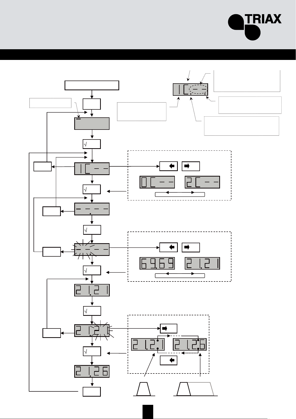
75
SE
6. Programmering
6.1 CHAN (kanal) meny
26
21
Programmering
meny
'
'
X
esc
'
+
0
-
0
'
'
'
'
'
X
esc
/
X
esc
/
X
esc
/
X
esc
/
Välj önskad filter
Välj stopp kanal
+
0
-
/
21
1kanal max. 6 kanaler
C – kanal meny
Start kanal.
Om filtret ej används, syns “--“ i
displayen.
C = kanal meny
Om dioden lyser = filtret tar
emot fler kanaler – max 6
kanale
r
Val av filter
– från 1 till 10
(0 = filter nr 10)
+
0
-
0
Välj start kanal
Om dioden inte lyser = samma
kanal är programmerad på fler filter
(ex. P1->ch.21 och P2->ch.21)
Page 76

76
TMB Programmable Multiband Amplier
TMB 10A • TMB 10B • TMB 10S
SE
6.2 LEVEL (nivå) meny
Programmering
meny
'
'
+
0
-
0
'
Välj ingång/filter
L – nivå meny
+
0
-
0
Justera till önskat värde
1=max dämp
'
X
esc
'
Dämpning, 1 – 20dB.
(20 ger max utnivå )
L = Nivå meny
1…0 = nr på filter 1..10
H – VHF band (BIII)
F – FM band (BI/FM)
A – (AUX)
G – AGC
Page 77
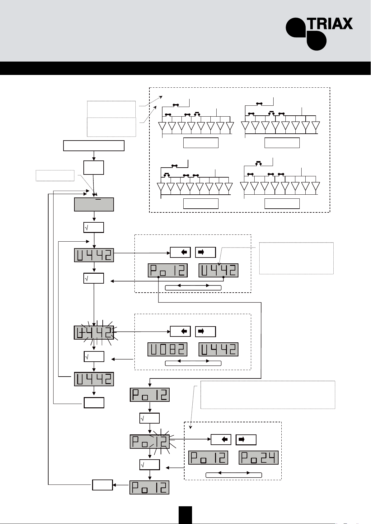
77
SE
6.3 IN (inkanal) menu
Programmering
meny
'
'
+
0
-
0
'
Val i undermeny
IN = inkanal meny
U = välj switchlägen S1…S4;
Po –Val av spänning: 12V DC
eller 24V DC till extern antenn
förförstärkare.
'
X
esc
'
442 – S4-av; S1, S2, S3-på;
352 – S3-av; S1, S2, S4-på;
172 – S2-av; S1, S3, S4-på;
082 – S1-av; S2, S3, S4-på;
+
0
-
0
Val av switch S1…S4
'
+
0
-
0
Val av spänning ut
'
X
esc
/
Val av spänning ut på antenningång UHF1…UHF3 för att driva
extern förförstärkare. Om impedansen på ingången är ≤ 75 Ω,
slår TMB förstärkaren automatiskt av spänningen på aktuell
ingång.
P1 P3 P4 P5 P6 P7 P8
S1
S2 S3 S4
P2
P1 P3 P4 P5 P6 P7 P8
S1
S2 S3 S4
P2
P1 P3 P4 P5 P6 P7 P8
S1
S2 S3 S4
P2
P1 P3 P4 P5 P6 P7 P8
S1
S2 S3 S4
P2
U 442 U 352
U 172 U 082
Konfiguration av switchar S1…S2
TMB0-10 B / S
42 – S4-av; S1, S2, S3-på
33 – S3-av; S1, S2, S4-på
15 – S2-av; S1, S3, S4-på
-
-
TMB-10 A
Page 78

78
TMB Programmable Multiband Amplier
TMB 10A • TMB 10B • TMB 10S
SE
6.4 SAT meny
Programmering
meny
'
'
+
0
-
0
'
Val av SAT ingång
SAT – meny
+
0
-
0
√ enter
'
+
0
-
0
Val i undermeny
√ enter
'
Dämpning
X
esc
'
X
esc
'
LE – Dämpning: 01…20
Po – Ström / polarisation för LNB: 0 eller 13 eller 17V DC
to – signal 22kHz på / av
E – korrigering på / av,
- Vid läge on: -12dB i början av bandet och 0dB i slutet,
- Vid läge off: 0dB.
Korrigering - ON
Korrigering - OFF
Page 79

79
SE
6.5 AUTO menu
Programmering
meny
'
'
'
AUTO – meny
√ enter
'
+
0
-
0
√ enter
'
Ställ in önskad nivå
X
esc
'
X
esc
'
min. max.
+
0
-
0
Val i undermeny
'
'
+
0
-
0
'
X
esc
'
X
esc
'
OBSERVERA!
När AGC är på = ON, i huvudmenyn finns inga
andra funktioner möjliga. Dioden blinkar på
position “5” (AUTO) i LED displayen när
förstärkaren är i AUTO mode. Önskas normal
läge, tryck ENTER och ändra AGC funktionen
till OFF.
+
0
Autonivå på utkanal gäller aktivt filter
Kanal
Aktivt filter
Page 80
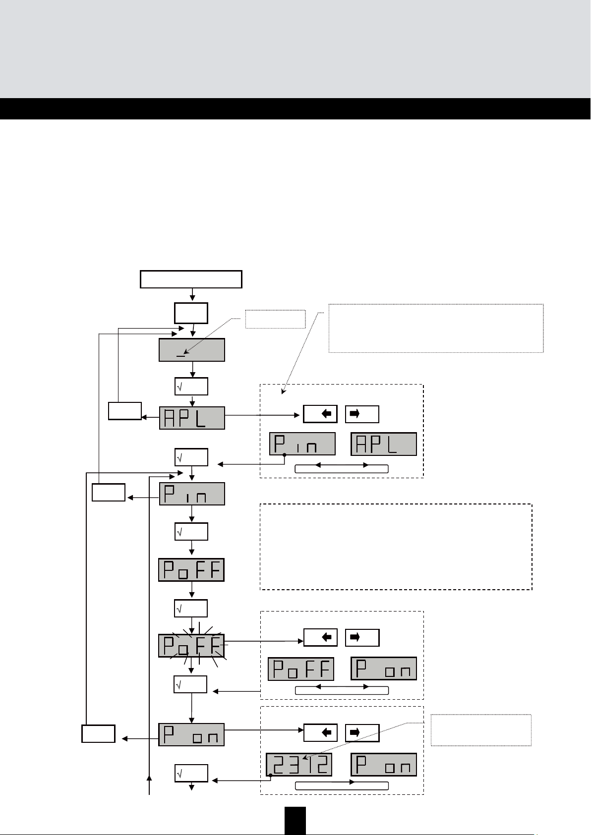
80
TMB Programmable Multiband Amplier
TMB 10A • TMB 10B • TMB 10S
SE
6.6 CARD (kort) meny
OBSERVERA!
APL meny – Stoppa in ett SD/MMC kort i läsaren och tryck på ENTER. Om kortet innehåller
korrekt mjukvara (filnamn tm_tmb10.tlp),ändras mjukvaran automatiskt och det kommer upp i
displayen “Boot” och förstärkaren startar från början. Om det inte är ett kort, eller korrekt filnamn, gör
förstärkaren en mjukvarureset (det ändrar inga inställningar).
EHP meny – Stoppa in ett SD/MMC kort i läsaren och tryck på ENTER. Om kortet ska kopiera
förstärkarens inställningar (filnamn: S00n.tmb) fungerar det om det i displayen syns “Good”. Om det
inte är ett korrekt kort syns det i displayen “Err”.
InP meny – Stoppa in ett SD/MMC kort i läsaren och tryck på ENTER. Om kortet har filnamn
“S00n.tmb”, kommer alla värden på kortet kopieras till förstärkaren om det i displayen står “Good”.
Om det inte är ett korrekt kort syns det i displayen “Err”
Programmering
meny
'
'
'
KORT – meny
X
esc
'
+
0
-
0
Val i undermeny
APL – Laddar in ny mjukvara
EHP – exporterar inställningarna till MMC/SD kortet
InP – importerar inställningarna till MMC/SD kortet
Pin – slår på/av och val av PIN kod
'
'
+
0
-
0
'
X
esc
'
+
0
-
0
'
Forts. nästa sid
X
esc
'
OBSERVERA!!!
Fabriks PIN kod: 2312
OBSERVERA!!!
SD/MMC kortet måste vara formaterat in FAT16 (FAT i
Windows) fil system (ej FAT32). Kontrollera i er PC
operationssystem hur en formatering görs. Alla filer
(mjukvara och inställningar) måste vara placerade i root
mappen på kortet.
Page 81
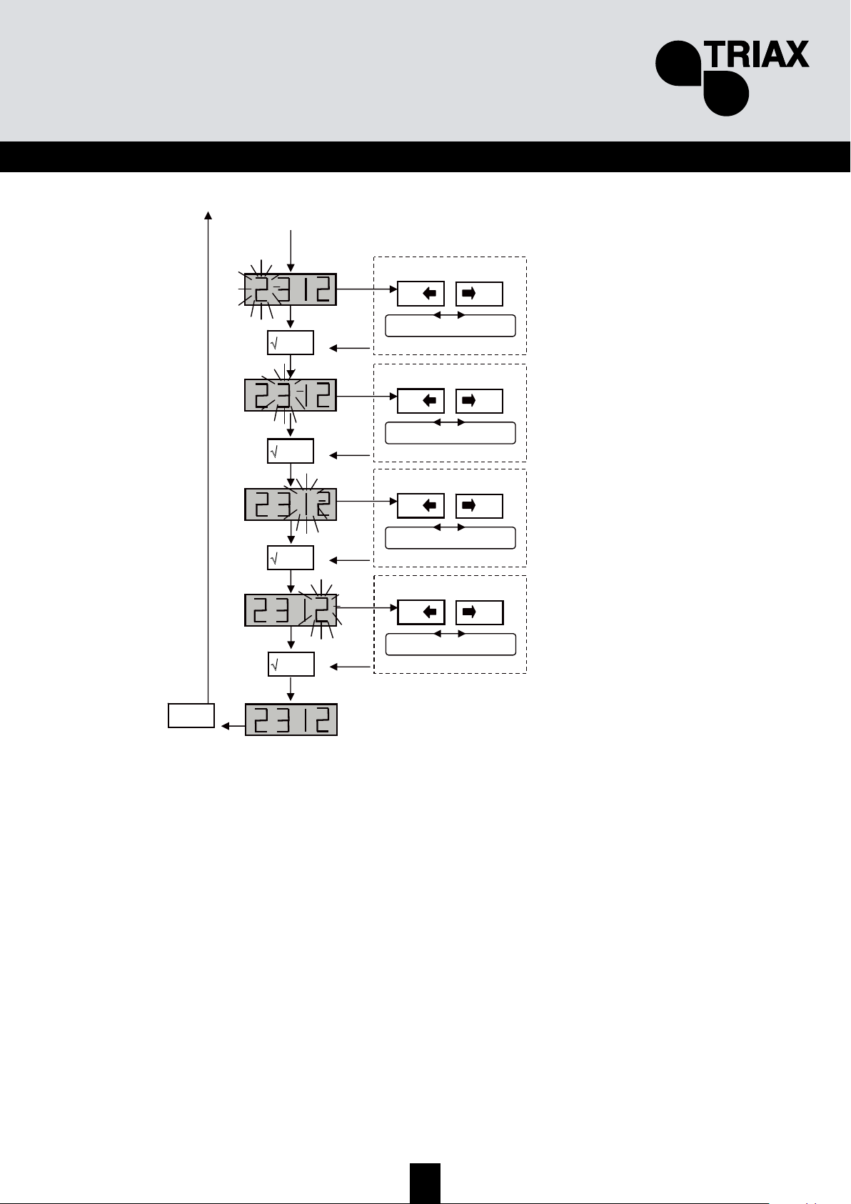
81
SE
Från föregående sid
'
+
0
-
0
0…9
'
'
'
X
esc
'
+
0
-
0
0…9
+
0
-
0
0…9
+
0
-
0
0…9
TIPS!
Om PIN koden är aktiverad (ON), har man åtkomst till menyerna först efter att rätt PIN kod är utförd Man
behöver inte slå in PIN koden igen, om man arbetar genom menyerna inom 30 sekunder. Efter den tiden
måste PIN koden slås igen. Om ni glömt PIN koden, så måste ni stänga av förstärkaren, hålla in ESC och
slå på förstärkaren igen. Alla inställningar blir resetade inklusive PIN funktionen.
Page 82
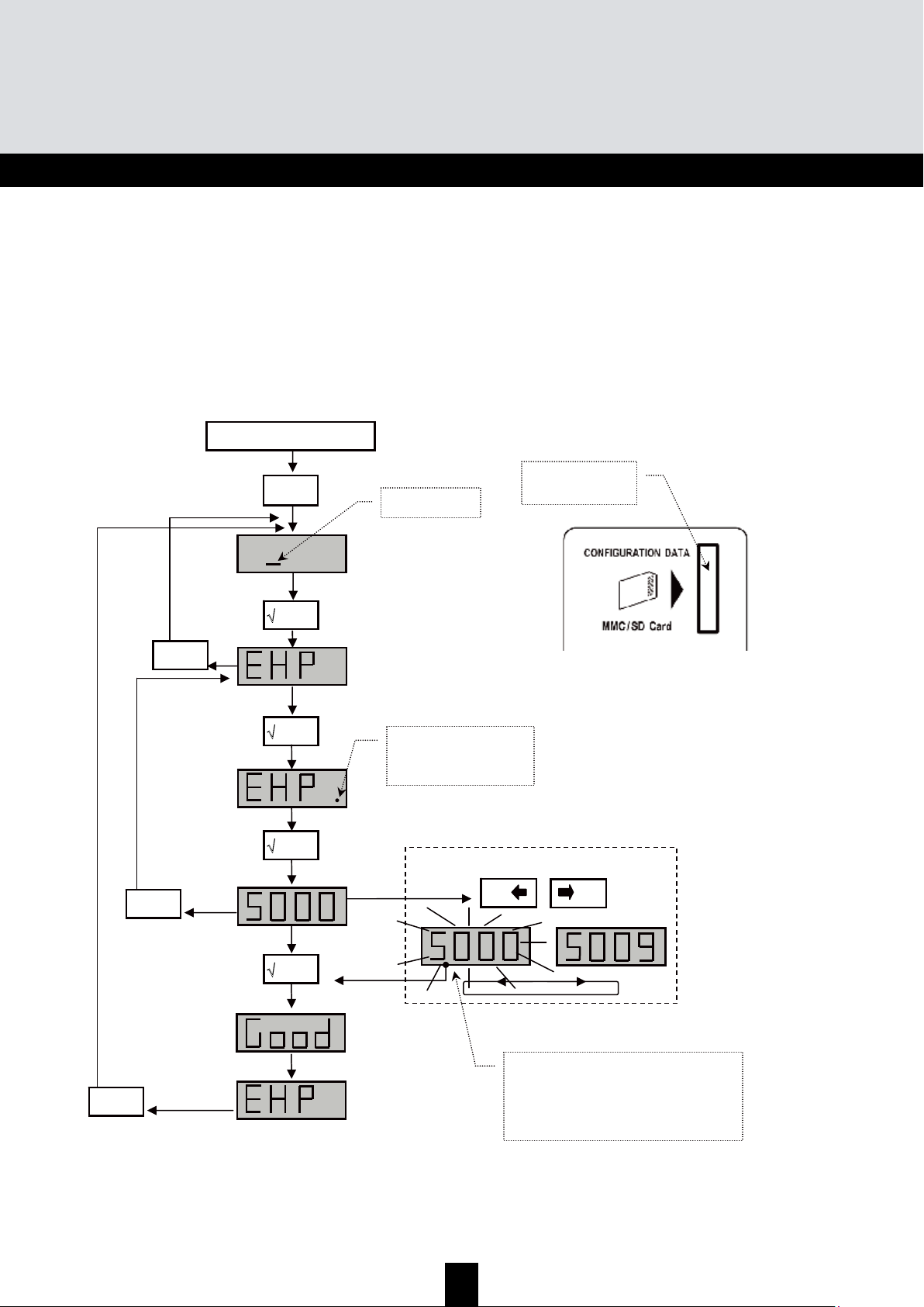
82
TMB Programmable Multiband Amplier
TMB 10A • TMB 10B • TMB 10S
SE
6.6.1 EHP (Exportering meny)
Programmering
meny
'
'
'
KORT – meny
X
esc
'
'
X
esc
'
+
0
-
0
X
esc
'
Stoppa in SD/MMC
kortet i läsaren
OBSERVERA!
Om filnumret blinkar, finns redan
denna fil på MMC / SD kortet. Trycker
ni på ENTER knappen blir existerande
fil överskriven.
Val av fil
OBSERVERA!!!
SD/MMC kortet måste vara formaterat i FAT16 (FAT i Windows) fil system (ej FAT32)
Kontrollera i er PC hur formattering går till. Alla filer (mjukvara och inställningar) måste ligga i root
mappen på kortet.
'
När DIODEN lyser
fungerar kortet korrekt
Page 83
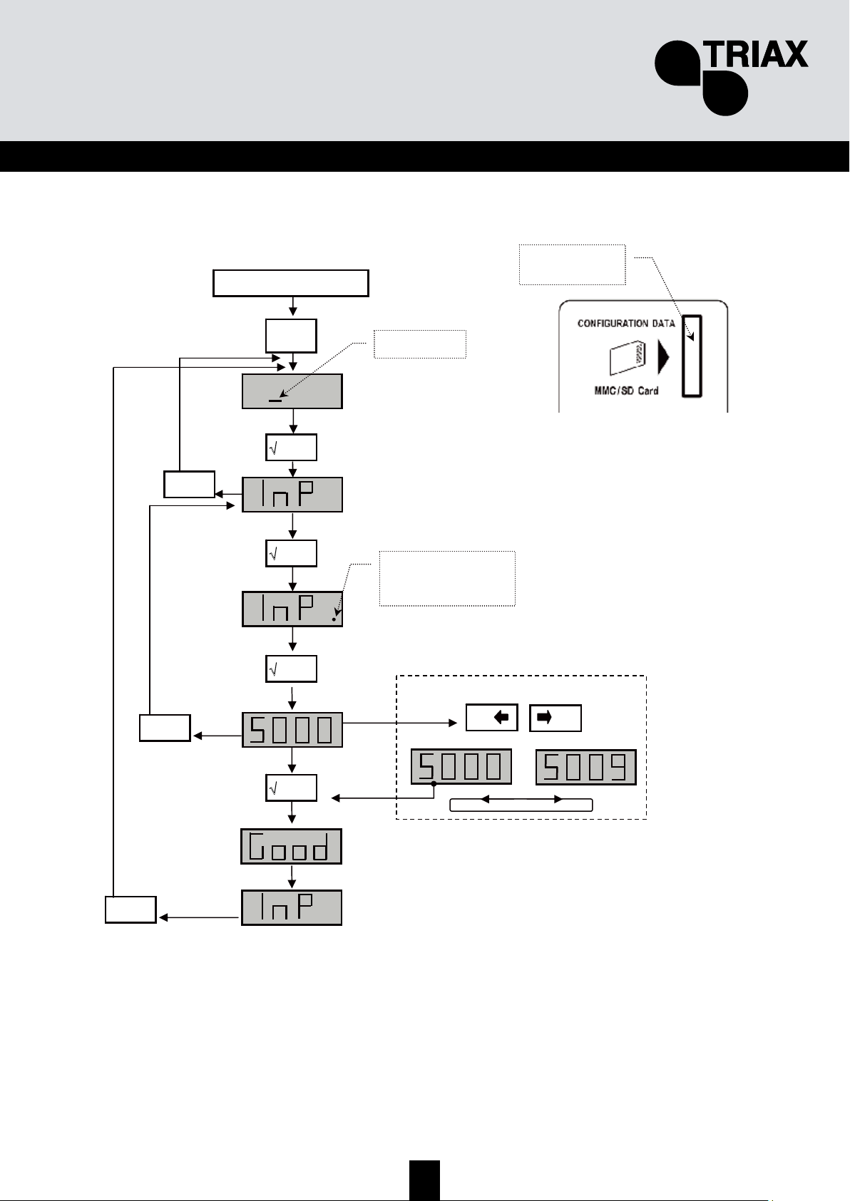
83
SE
6.6.2 InP (Importerings meny)
7. ÅTERSTÄLL till fabriksinställningar
Håll in ESC knappen, anslut nätsladden, alla inställningar försvinner. Det kommer upp siffror
“8888” i displayen
Programmering
meny
'
'
'
KORT – meny
X
esc
'
'
X
esc
'
+
0
-
0
X
esc
'
Stoppa SD/MMC
kortet i läsaren
Val av fil
'
När DIODEN lyser
fungerar kortet korrekt
Page 84
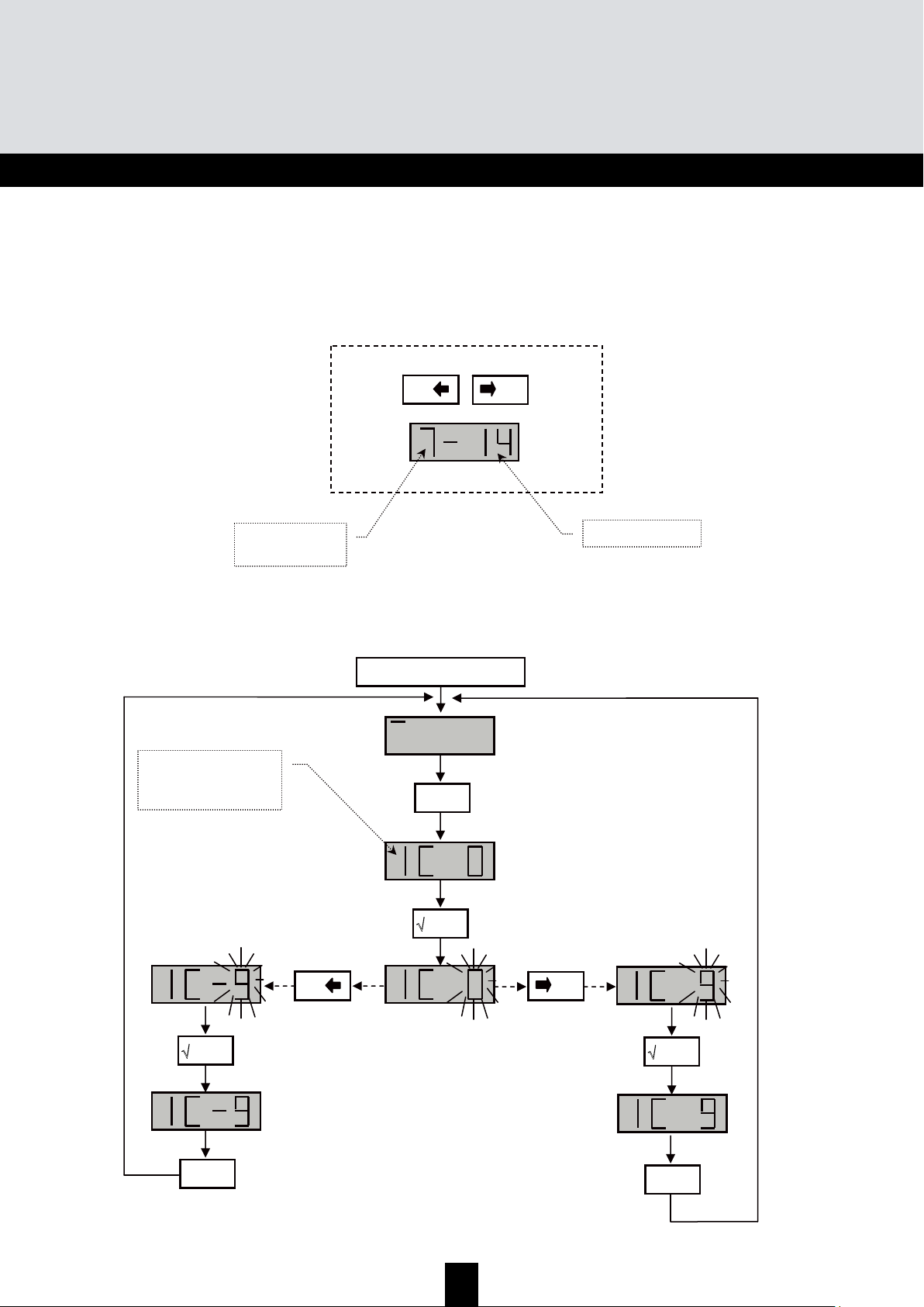
84
TMB Programmable Multiband Amplier
TMB 10A • TMB 10B • TMB 10S
SE
8. Extra funktioner
8.1 Mjukvaru version
Tryck “+” och “-“ knappen, i LED displayen visas:
8.2 Fin inställning
+
0
-
0
och
Veckonr
Sista årsiffran:
Programmering
X
esc
'
'
+
0
-
0
'
'
X
esc
'
X
esc
'
Fin inställning fungerar
bara på aktuellt filter!
Page 85
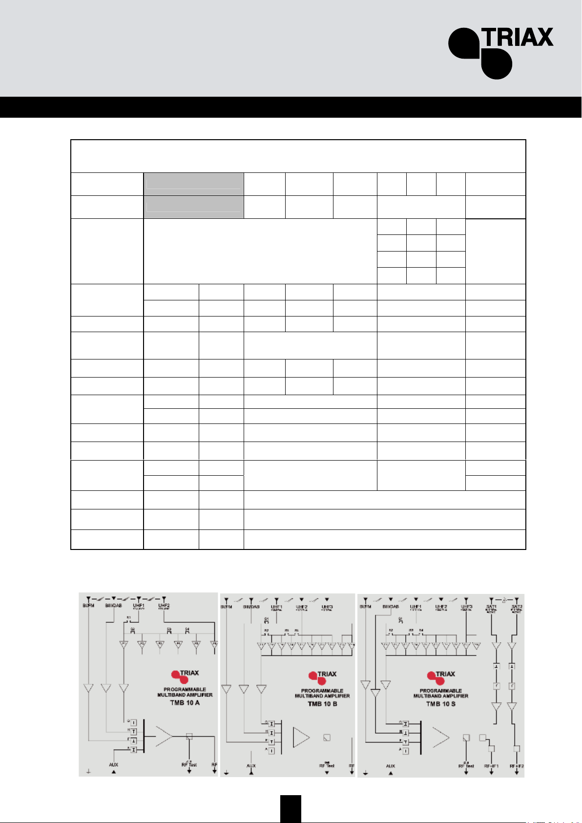
85
SE
9. Tekniska specifikationer
* Endast TMB-10S modell
TMB-10 A/B/S
Ingångar BI-FM BIII-DAB AUX UHF 1 UHF 2 UHF 3 SAT 1,2*
Bandbredd 47 ... 108 174 ... 230 47 ... 862 470 ... 862 950 ... 2150
4 (4) 4 (2) 2 (-)
3 (3) 5 (3) 2 (-)
1 (1) 7 (5) 2 (-)
UHF filter
combination
(TMB-10 A/B/S)
/
- (-) 8 (6) 2 (-)
/
TMB-10 A/B dB 48 ±2 48 ±2 39 ±3 55 ±2 /
Förstärkning
TMB-10S dB 45 ±2 45 ±2 35 ±5 50 ±2 40 ±4
Dämpning / dB 20 20 20 20 20
Dämpning på
gemensam
utgång
/ dB - 20 /
Brus / dB 5 5 - 9 6
Max. Innivå / dBuV 90 90 90 80 /
TMB-10A/B dBuV 124 @-35dBc 124 @-60dBc /
Max. Utnivå
TMB-10S dBuV 118 @-35dBc 118 @-60dBc 118 @-35dBc
Selektivitet / dB/MHz / 16/16 40 @ 862
Försörjning av
förförstärkare
/ V/mA / 12-24/50 /
/ V/mA 0/13/17/300
Försörjning av
LNB
/ kHz/kHz
/ /
0/22
Test uttag / dB -20 ±2
Nätdel / V AC / VA 230 / 35
Arbets
temperatur
/ °C -5 …. +50
Page 86
86
TMB Programmable Multiband Amplier
TMB 10A • TMB 10B • TMB 10S
FIN
Y
Y
Y
l
l
l
e
e
e
i
i
i
s
s
s
t
t
t
i
i
i
e
e
e
t
t
t
o
o
o
a
a
a
TMB10 vahvistinsarjan toiminta perustuu selektiivisiin ja ohjelmoitaviin UHF-alueen kanavasuotimiin.
TMB10 –vahvistimissa on yksi monituloinen laajakaistainen vahvistin; 10 UHF -suodinta jotka kukin
voidaan ohjelmoida 1 - 6 kanavan leveydelle (8 - 48 MHz) ja kytkeä kolmeen vaihtoehtoiseen
tuloliittimeen.
Laitteessa voidaan jokainen suodin tai taajuusalue ohjelmoida yksilöllisesti ja valita sitten haluttu
lähtötaso.
TMB-10A – Ref.: 324575
5 tuloa:
BI - FM, BIII - DAB, AUX, UHF1, UHF2
UHF-vahvistus = 55 dB
BI – BIII -vahvistus = 48 dB
AUX -vahvistus = 39 dB
UHF-lähtötaso = 124 dBµV (DIN 45004B)
TMB-10B – Ref.: 324576
6 tuloa:
BI - FM, BIII - DAB, AUX, UHF1, UHF2, UHF3
UHF -vahvistus = 55 dB
BI - BIII -vahvistus = 48 dB
AUX -vahvistus = 39 dB
UHF-lähtötaso = 124 dBµV (DIN 45004B)
TMB-10S – Ref.: 324577
8 tuloa:
BI - FM, BIII - DAB, AUX, UHF1, UHF2, UHF3, 2 x SAT
SAT -vahvistus = 40 dB
UHF -vahvistus = 48 dB
BI - BIII -vahvistus = 43 dB
AUX -vahvistus = 33 dB
UHF-lähtötaso = 120 dBµV (DIN 45004B)
SAT-lähtötaso = 120 dBµV (EN 50083-3)
Page 87

87
FIN
T
T
T
u
u
u
r
r
r
v
v
v
a
a
a
l
l
l
l
l
l
i
i
i
s
s
s
u
u
u
u
u
u
s
s
s
o
o
o
h
h
h
j
j
j
e
e
e
i
i
i
t
t
t
a
a
a
Tärkeää: Tämän laitteen saa avata vain valtuutettu huoltohenkilö.
• Irroita laite sähköverkosta kytkentöjen ajaksi.
• Varmista vapaa ilmankulku (jäähdytys) laitteen ympärillä jotta se toimisi suunnitellulla lämpötila-
alueellaan. Vältä laitteen sijoittamista suljettuun tilaan ja varmista että tuuletusaukot ovat
esteettömiä.
• Varmista että mitään nestettä ei pääse laitteen sisälle.
• Älä asenna laitetta kosteaan tilaan. Jos laitteessa on merkkejä kosteudesta, anna sen kuivua
kokonaan ennen käyttöönottoa
• Varmista että virtajohto ja koaksiaalikaapelit ovat hyvässä kunnossa.
• Varmista että virtajohto on tarvittaessa asentajan ulottuvilla mutta lasten saavuttamattomissa.
Laitteen maadoitus
• Huomioithan että asennuksesi täyttää EN 50083 (conformity of collective installations) ja EN
60065 (standards in force for electrical protection) vaatimukset.
Sulakkeen vaihtaminen
• Vioittuneen sulakkeen saa vaihtaa vain valtuutettu huoltohenkilö.
Elektromagneettinen kelpoisuus (EMC)
• Varmista että kaikki kotelon ruuvit on kiristetty huolella.
• Varmista että kaapelit ja liittimet eivät ole ruosteessa.
Page 88
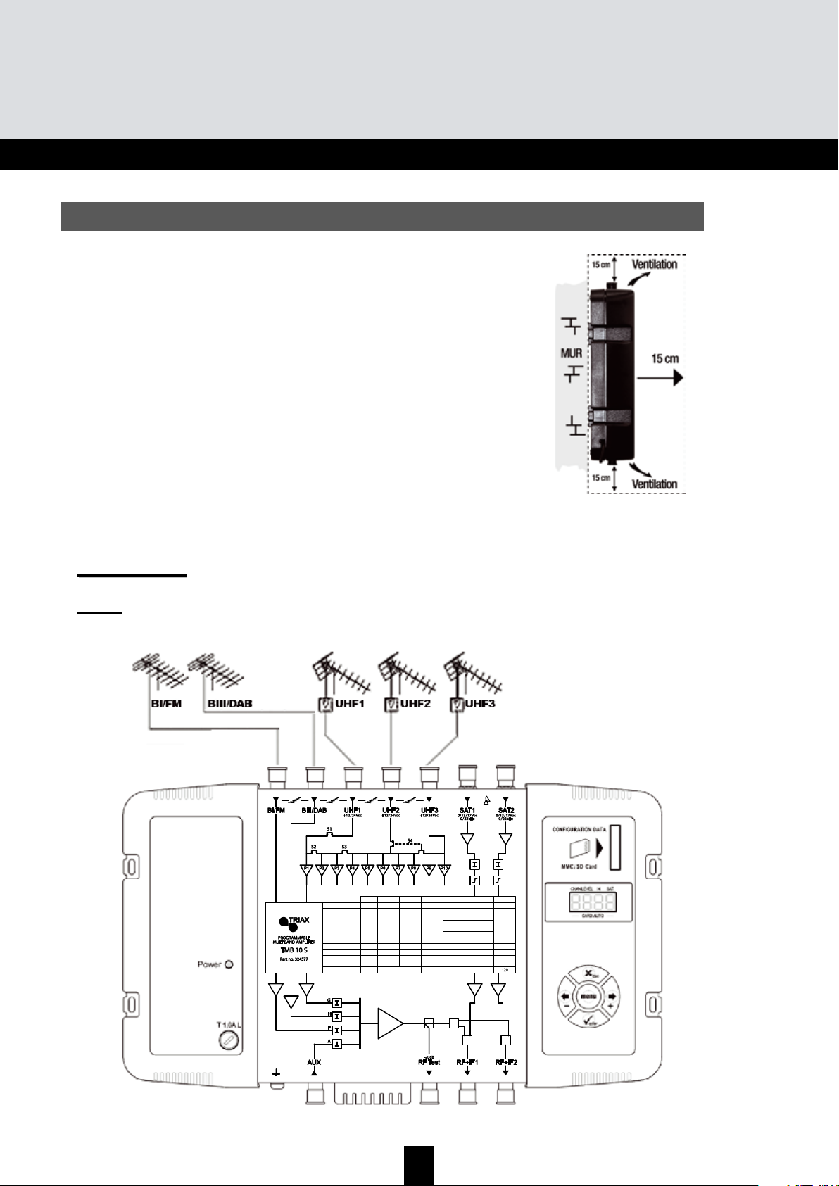
88
TMB Programmable Multiband Amplier
TMB 10A • TMB 10B • TMB 10S
FIN
L
L
L
a
a
a
i
i
i
t
t
t
t
t
t
e
e
e
e
e
e
n
n
n
a
a
a
s
s
s
e
e
e
n
n
n
n
n
n
u
u
u
s
s
s
Suosittelemme että laite asennetaan riittävästi tuuletettuun tilaan.
Luonnollisen ilmanvaihdon tulisi tapahtua tuuletusaukkojen kautta;
varmista että jätät vähintään 15 cm tilaa laitteen ympärille.
Suosittelemme että irroitat virtajohdon laitteen kytkentöjen ajaksi.
L
L
L
a
a
a
i
i
i
t
t
t
t
t
t
e
e
e
e
e
e
n
n
n
a
a
a
s
s
s
e
e
e
n
n
n
n
n
n
u
u
u
s
s
s
Suosittelemme että laite asennetaan riittävästi tuuletettuun tilaan.
Luonnollisen ilmanvaihdon tulisi tapahtua tuuletusaukkojen kautta;
varmista että jätät vähintään 15 cm tilaa laitteen ympärille.
Suosittelemme että irroitat virtajohdon laitteen kytkentöjen ajaksi.
KKyyttkkeennnnäätt
Huom:
UHF-tuloissa on oikosulkusuojattu esivahvistimen käyttöjännite (12 tai 24V, 50mA max.)
Esivahvistimen tunnistus on automaattinen, vain käyttöjännite valitaan ohjelmallisesti.
Max. Output level*
Max. Input level
Noise
Attenuator
Gain (typical)
UHF lter setting
Frequency range MHz
Unit
dBµV
dBµV
dB
dB
dB
47÷108
BI-FM
116
80
5
0…20
43
/
174÷230
BIII-DAB
80
5
0…20
43
/
47÷862
AUX
80
10
0…20
33
/
UHF1
120
–
1
3
–
1
3
470÷862
UHF2
80
9
0…20
48
–
–
–
8
7
5
UHF3
10
9
7
2
2
2
950÷2150
SAT
79
6
0…20
40
/
*DIN 45004B
Page 89
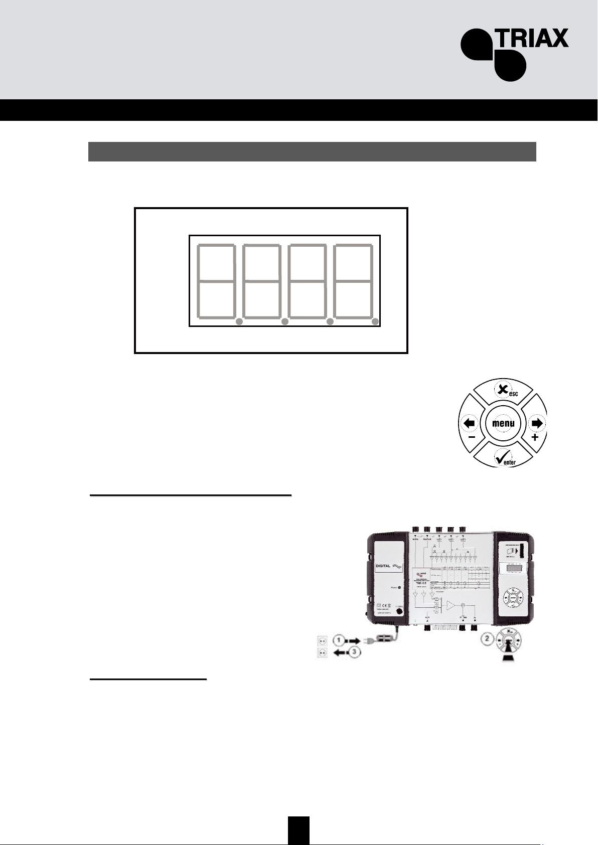
89
FIN
O
O
O
h
h
h
j
j
j
e
e
e
l
l
l
m
m
m
o
o
o
i
i
i
n
n
n
t
t
t
i
i
i
Laite ohjelmoidaan sisäänrakennetun näytön ja näppäimistön avulla.
Kun laite käynnistetään:
• Ohjelmointitila on valmiustilassa:
• Esiasetus:
o UHF1 Î 3 UHF -suodinta
o UHF2 Î 0 UHF -suodinta
o UHF3 Î 7 UHF -suodinta
• Kaikki UHF-suotimet ovat deaktivoituna (näyttö "
- -"),
• Vaimennus on nollassa
TTeehhddaassaasseettuusstteenn ppaallaauuttuuss
Laite palautetaan tarvittaessa tehdasasetuksiin seuraavasti:
1. Irroita virtajohto
2. Paina
esc-näppäintä ja pidä se alhaalla
3. Kytke virtajohto
Kaikki ohjelmoinnit poistuvat (myös PIN-koodi)
ja laite palautuu valmiustilaan.
Voit vapauttaa
esc –näppäimen kun näytössä on “8888”
VVaallmmiissttuussppääiivvä
ä
Saat laitteen valmistuspäivän selville painamalla 2 sekuntia näppäimiä
- & +, jolloin näyttöön tulee
valmistuspäivä muodossa; A-SS jossa A ilmaisee valmistusvuoden viimeisen numeron ja SS
valmistusviikon.
Digit 1 Digit 2
Di
g
it 3
Di
g
it 4
CHAN LEVEL IN SAT
____ AUTO CARD ____
Page 90

90
TMB Programmable Multiband Amplier
TMB 10A • TMB 10B • TMB 10S
FIN
AAsseettuukksseett
Kun laite kytketään päälle niin näytössä näkyy liikkuva ja vilkkuva osoitin.
T
T
T
o
o
o
i
i
i
m
m
m
i
i
i
n
n
n
t
t
t
a
a
a
p
p
p
e
e
e
r
r
r
i
i
i
a
a
a
a
a
a
t
t
t
e
e
e
Pääset asetustilaan painamalla menu –näppäintä kunnes osoitin on haluamassasi kohdassa. Paina
sitten enter –näppäintä.
Yhteenveto:
• Valitse haluamasi toiminto menu -näppäimellä.
• Siirry valikkoon painamalla enter.
• Poistu valikosta painamalla uudestaan menu.
Huom:
Jos näppäimiin ei kosketa ohjelmointitilassa minuutin kuluessa, laite palautuu valmiustilaan.
V
V
V
a
a
a
l
l
l
i
i
i
k
k
k
o
o
o
t
t
t
CHAN
UHF-suotimien ohjelmointi:
• Kanava
• Kaistanleveys (1 - 6 kanavaa; 8 - 48 MHz)
LEVEL
Vaimentimien ohjelmointi.
IN
UHF1, 2 ja 3 tulojen ohjelmointi.
Esivahvistimen käyttöjännitteen valinta (12 tai 24 V
DC
).
AUTO
AGC-toiminnon ohjelmointi.
UHF –kanavien automaattinen tason säätö.
CARD
Ohjelmoinnin tallennus ja kopiointi.
PIN-koodin aktivointi ja muuttaminen.
SAT
IF-vaimentimien ohjelmointi.
9 dB taajuuskorjaus ON/OFF
Syöttöjännitteen valinta (0, 13 tai 17 V
DC
).
22 kHz –valinta (ON/OFF).
C
C
C
H
H
H
A
A
A
N
N
N
-
-
-
v
v
v
a
a
a
l
l
l
i
i
i
k
k
k
k
k
k
o
o
o
TMB-vahvistimissa on joko 6 tai 10 ohjelmoitavaa UHF-suodinta. UHF-suotimet voidaan kytkeä
Page 91
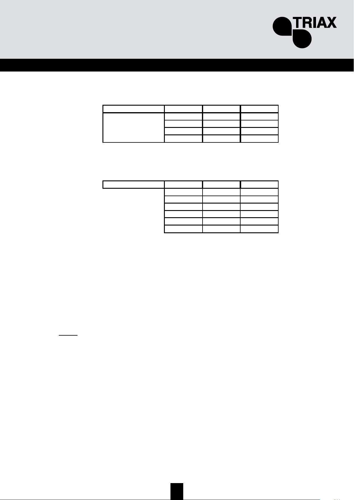
91
FIN
TMB 10A
Tulo UHF1 UHF2 UHF3
423315-
-6-
Suotimia/UHF-tulo
TMB 10B & S
Tulo UHF1 UHF2 UHF3
352
172
-82
3-7
1-9
- - 10
Suotimia/UHF-tulo
Jokainen UHF-suodin voidaan ohjelmoida kaistanleveyksille 8 - 48 MHz (1 - 6 kanavaa).
U
U
U
H
H
H
F
F
F
-
-
-
s
s
s
u
u
u
o
o
o
t
t
t
i
i
i
m
m
m
i
i
i
e
e
e
n
n
n
t
t
t
u
u
u
l
l
l
o
o
o
k
k
k
y
y
y
t
t
t
k
k
k
i
i
i
m
m
m
e
e
e
t
t
t
Siirry IN –valikkoon siirtämällä näytön osoitin kohtaan IN ja painamalla sitten enter.
• Paina uudestaan enter vaihtaaksesi UHF-tulokytkimien tilaa
• Vaihda tulokytkimien tilaa + tai – näppäimiä painamalla
Huom:
Jokainen UHF-suodin voidaan tarvittaessa deaktivoida. Valitse ko. suotimelle arvo – "CHAN" valikossa.
Page 92

92
TMB Programmable Multiband Amplier
TMB 10A • TMB 10B • TMB 10S
FIN
Aloitus
menu
'
'
+
0
-
0
tai
'
Valitse alivalikko
IN – tulovalikko
U – UHF-tulokytkimien valinta UHF1,
UHF2 ja UHF3 tuloille;
Po – Esivahvistimen syöttöjännitteen
valinta: 12V DC tai 24VDC
'
X esc
'
+
0
-
0
tai
Valitse UHF-suotimien tulokytkentä
'
+
0
-
0
tai
Esivahvistimen jännite
'
X
esc
/
Tässä valikossa valitaan sopiva esivahvistimen
syöttöjännite tuloille UHF 1, 2 and 3. Laite tunnistaa
kytketyn esivahvistimen automaattisesti ja kytkee
syöttöjännitteen päälle.
UHF-suotimien tulokytkimet
352
172
082
307
109
001
Irroita laite sähköverkosta ennen
kuin teet kaapelikytkennät
Page 93

93
FIN
U
U
U
H
H
H
F
F
F
-
-
-
s
s
s
u
u
u
o
o
o
t
t
t
i
i
i
m
m
m
e
e
e
n
n
n
l
l
l
e
e
e
v
v
v
e
e
e
y
y
y
s
s
s
(
(
(
C
C
C
H
H
H
A
A
A
N
N
N
-
-
-
v
v
v
a
a
a
l
l
l
i
i
i
k
k
k
k
k
k
o
o
o
)
)
)
26
21
Aloitus
menu
'
'
X esc
'
+
0
-
0
tai
'
'
'
'
'
X esc
/
X esc
/
X esc
/
X esc
/
Valitse asetettava suodin
+
0
-
0
tai
V
alitse aloituskanava
Valitse lopetuskanava
+
0
-
/
21
1 kanava max. 6 kanavaa
CHAN – valikko
Suotimen alkukanava.
Jos suodin ei ole käytössä,
näytössä on “--“.
Suotimen numerot 1 - 10
(0 = no. 10)
Piste näytössä vilkkuu kun
suotimen leveys > 1 kanava.
C –Channel-
valikko
Page 94

94
TMB Programmable Multiband Amplier
TMB 10A • TMB 10B • TMB 10S
FIN
H
H
H
i
i
i
e
e
e
n
n
n
o
o
o
s
s
s
ä
ä
ä
ä
ä
ä
t
t
t
ö
ö
ö
Hienosäätöä käytetään tarvittaessa vastaanotettavan signaalin vaatimaan hienosäätöön.
Tarkista offset-asetus mittalaitteellasi.
Aloitus
'
X
esc
'
0
0
Säätö vaikuttaa vain
valittuun suotimeen
Valitse haluttu suodin + ja
– näppäimillä
'
'
X esc
'
X esc
'
Page 95

95
FIN
Tasojen asetus.
TMB-vahvistimissa on kolme erilaista tason säätöä:
• Lähtötasojen käsisäätö (LEVEL-valikko)
• Suotimien automaattinen lähtötasojen säätö käyttäjän asettamaan tasoon. (Auto-valikko,
alivalikko LEU)
• Automaattinen UHF-alueen vahvistuksen säätö (Auto-valikko, alivalikko AGC)
V
V
V
a
a
a
i
i
i
m
m
m
e
e
e
n
n
n
n
n
n
u
u
u
k
k
k
s
s
s
e
e
e
n
n
n
s
s
s
ä
ä
ä
ä
ä
ä
t
t
t
ö
ö
ö
(
(
(
L
L
L
E
E
E
V
V
V
E
E
E
L
L
L
-
-
-
v
v
v
a
a
a
l
l
l
i
i
i
k
k
k
k
k
k
o
o
o
)
)
)
Siirry LEVEL-valikkoon siirtämällä osoitin kohtaan LEVEL ja paina enter-näppäintä.
• Valitse säädettävä kanava + tai - näppäimillä.
•
Vahvista valinta painamalla enter
• Vaimennusta voidaan säätää näytön vilkkuessa (20 ilmaisee vaimennuksen 0; 1 tarkoittaa
max. vaimennusta)
• Vahvista valinta painamalla enter
X
esc
'
Aloitus
menu
'
'
+
0
-
0
tai
'
Valitse alivalikko
L – level valikko
Vaimennus -1 … -20 dB
L –LEVEL valikko
1…0 – suotimen numero 1 - 10
H – VHF alue (BIII)
F – FM alue (BI/FM)
A – aux-tulo (AUX)
G – UHF vahvistus
+
0
-
0
tai
Valitse vaimennusarvo
'
Page 96
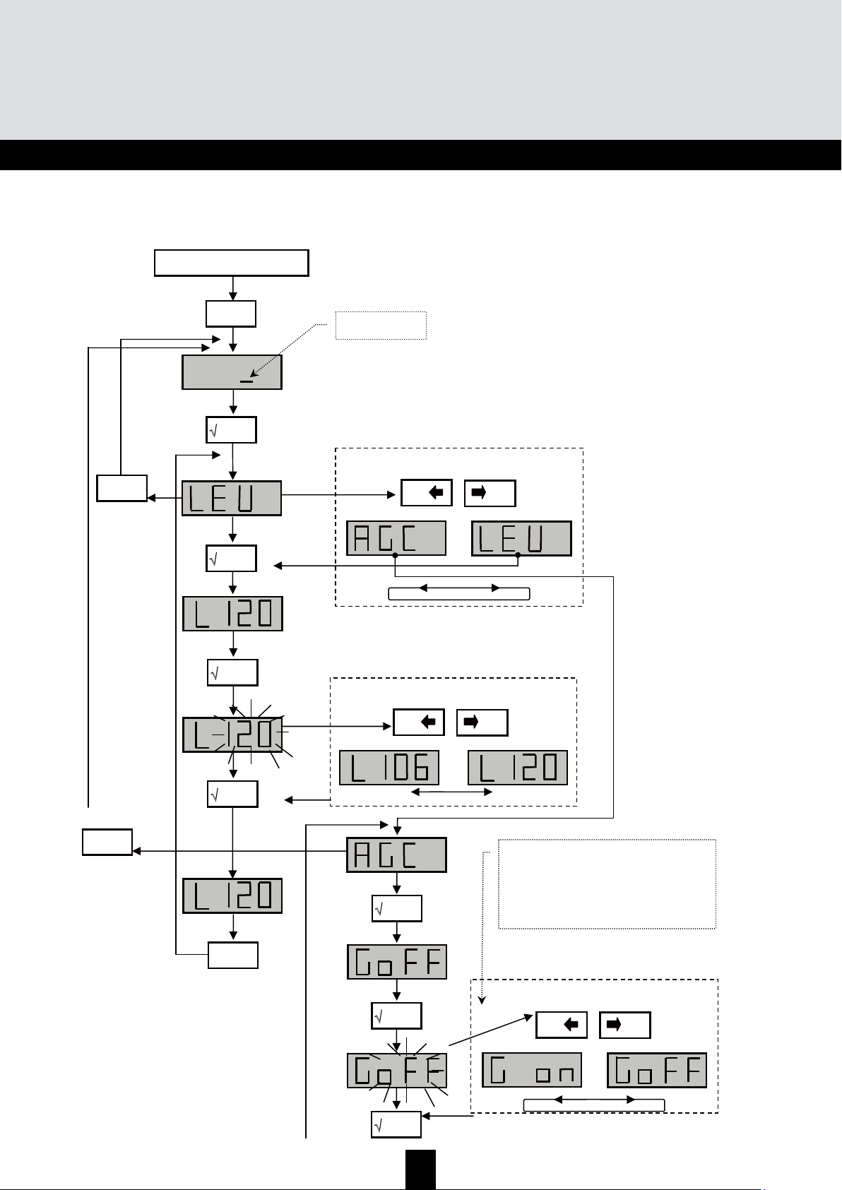
96
TMB Programmable Multiband Amplier
TMB 10A • TMB 10B • TMB 10S
FIN
A
A
A
u
u
u
t
t
t
o
o
o
m
m
m
a
a
a
a
a
a
t
t
t
t
t
t
i
i
i
n
n
n
e
e
e
n
n
n
U
U
U
H
H
H
F
F
F
–
–
–
v
v
v
a
a
a
h
h
h
v
v
v
i
i
i
s
s
s
t
t
t
u
u
u
k
k
k
s
s
s
e
e
e
n
n
n
s
s
s
ä
ä
ä
ä
ä
ä
t
t
t
ö
ö
ö
v
v
v
a
a
a
l
l
l
i
i
i
k
k
k
k
k
k
o
o
o
Huom: Alueiden BI-II / BIII / AUX -tasojen säätö ei ole automaattinen.
Aloitus
menu
'
'
'
AUTO – valikko
√ enter
'
+
0
-
0
tai
√ enter
'
Lähtötason näyttö
X
esc
'
X esc
'
min. max.
+
0
-
0
tai
Valitse alivalikko
'
'
+
0
-
0
tai
'
X esc
'
TÄRKEÄÄ!
Laite muistaa keskimääräisen lähtötason. ± 1 dB
muutos laukaisee vahvistuksen ja vaimennuksen
säätötoiminnon.
AGC-tila piilottaa muut valikot. Jos haluat säätää
arvoja manuaalisesti, kytke AGC pois käytöstä.
Page 97
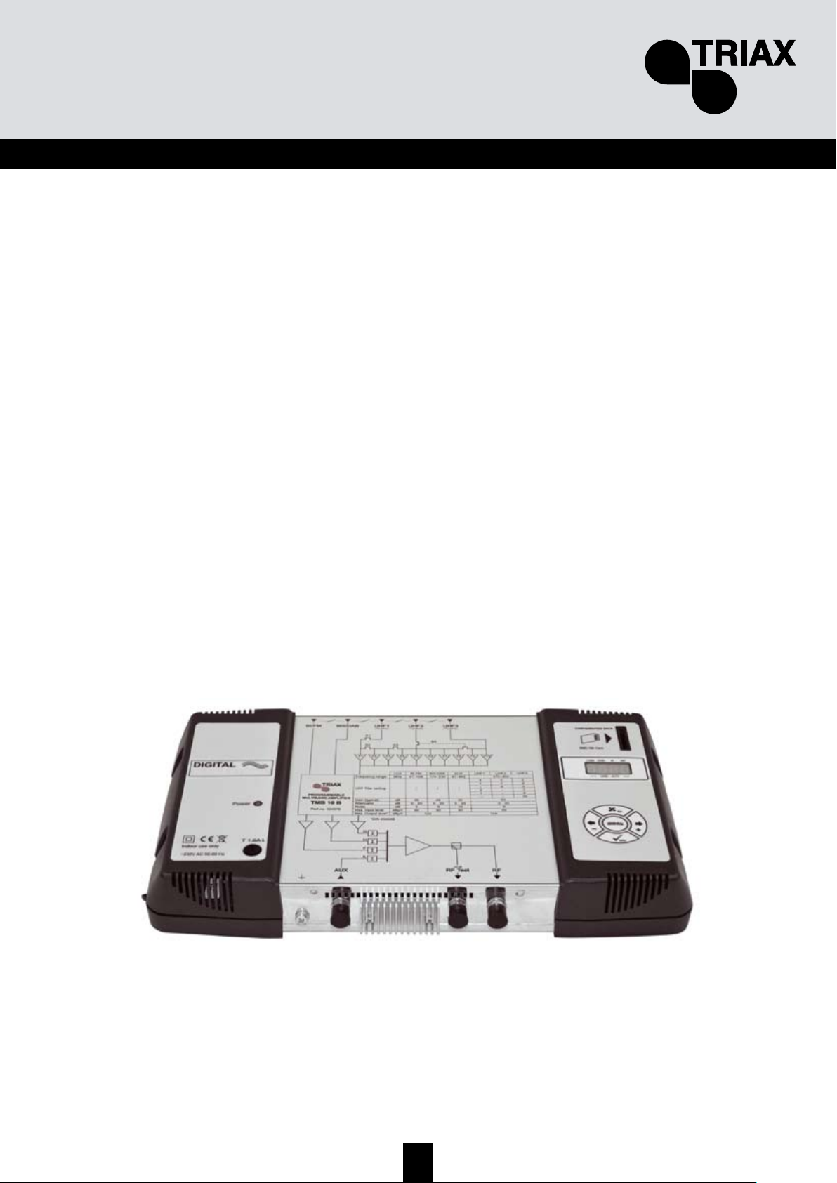
97
FIN
C
C
C
A
A
A
R
R
R
D
D
D
-
-
-
v
v
v
a
a
a
l
l
l
i
i
i
k
k
k
k
k
k
o
o
o
TMB –vahvistimessa on SD/MMC –korttien lukupaikka joka mahdollistaa asetusten kopioinnin
laitteesta toiseen.
Tässä valikossa on 4 alivalikkoa:
• APL laiteohjelmiston päivitys
Jos kortti sisältää päivitysohjelmiston (tm_tmb10.tlp), niin laite päivittyy automaattisesti enternäppäimen painamisen jälkeen; näytössä näkyy teksti "boot" päivitysoperaation ajan.
• EHP asetusten siirto vahvistimesta muistikortille
Valitse EHP-alivalikko ja valitse tiedosto.Näyttö vilkkuu jos samanniminen tiedosto on jo olemassa.
Enter-näppäintä painamalla tiedosto korvataan uudella.
• InP asetusten siirto muistikortilta vahvistimeen
Valitse InP-alivalikko ja sitten luettava tiedosto. Enter-näppäintä painamalla tiedoston luku alkaa;
näytössä näkyy "Good" kun siirto on valmis.
• PIN PIN-koodin aktivointi ja muuttaminen
PIN-koodin ollessa aktivoituna se tarvitaan aina valikoihin siirryttäessä (anna PIN-koodi
näppäimistön avulla ja paina sitten enter). Jos mitään näppäintä ei paineta 30 s kuluessa laite
siirtyy takaisin valmiustilaan ja PIN-koodin antamista voidaan yrittää uudestaan.
Tärkeää!
• Jos siirryt APL, EHP tai InP –valikoihin eikä laitteeseen ole asetettu muistikorttia niin
näytössä näkyy viesti Err.
• SD/MMC –täytyy olla alustettuna muotoon FAT16. Kaikki tiedostot sijaitsevat kortin
juuritiedostossa.
• Asetustiedostot nimetään mallin mukaan seuraavasti (S00x : TMB10S, B00x : TMB10B,
A00x : TMB10A).
• PIN –koodin tehdasasetus on 2312.
Page 98
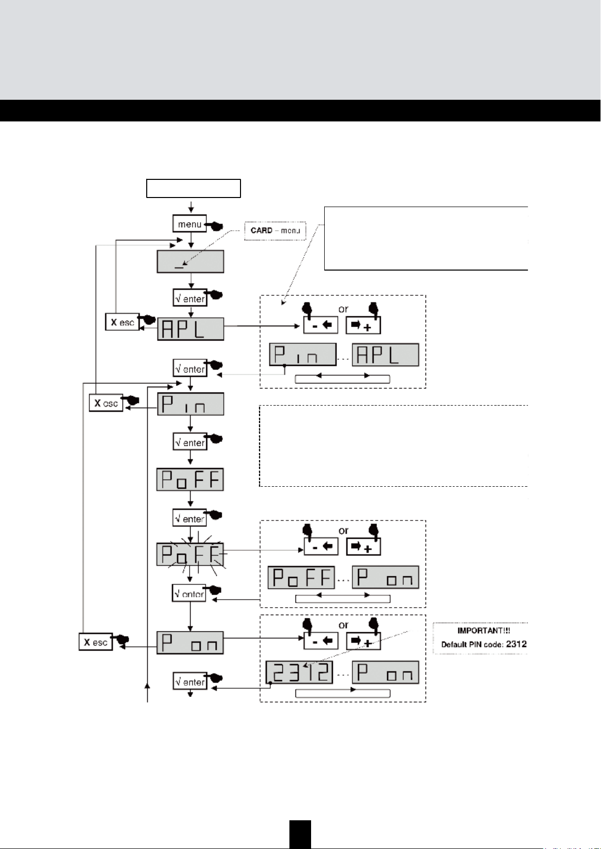
98
TMB Programmable Multiband Amplier
TMB 10A • TMB 10B • TMB 10S
FIN
CARD -valikko
Aloitus
Jatkuu seuraavalla sivulla
APL laiteohjelmiston päivitys
EHP asetusten siirto kortille
InP asetusten siirto kortilta
PIN -koodin aktivointi ja muuttaminen
SD/MMC on alu stettava muotoon F AT 16.
Tiedostot sijoitetaan juuritiedostoon.
Jos SD/MMC – kortilla ei ole tarvittavaa tiedostoa,
näytössä on uudelleen käynnistettäessä
viesti noFL.
Valitse alivalikko
Page 99
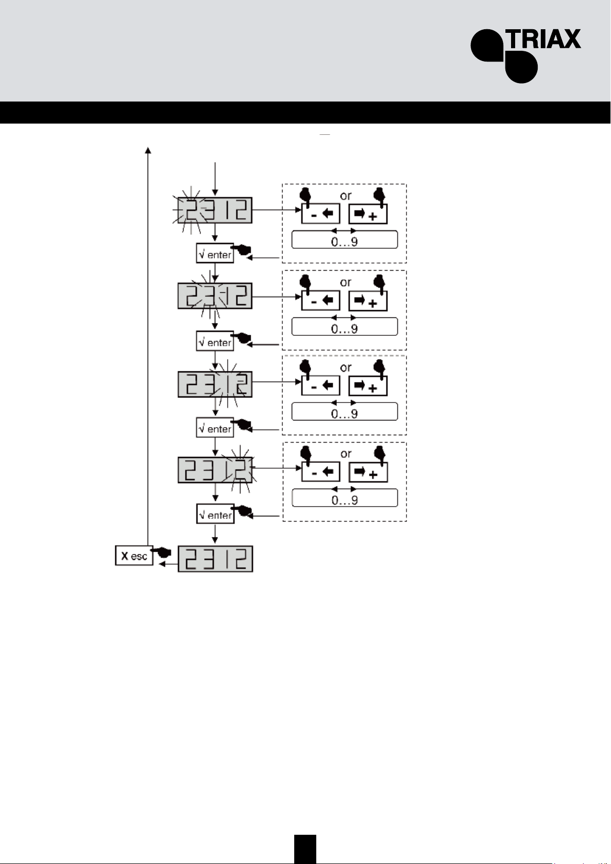
99
FIN
Jatkuu edelliseltä sivulta
Page 100
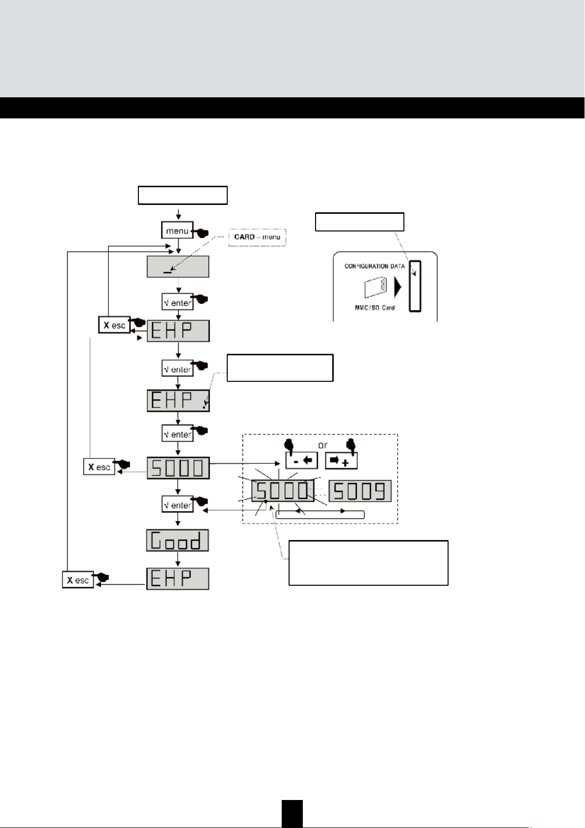
100
TMB Programmable Multiband Amplier
TMB 10A • TMB 10B • TMB 10S
FIN
EHP –asetusten vientivalikko
Aloitus
A
senna SD-kortti
Piste vilkkuu kun prosessi
alkaa
Näyttö vilkkuu kun tiedosto on luotu SD-
kortille.
Paina “enter” vahvistaaksesi .
V
alitse luettava tiedosto
 Loading...