

Page 1
Conguration guide
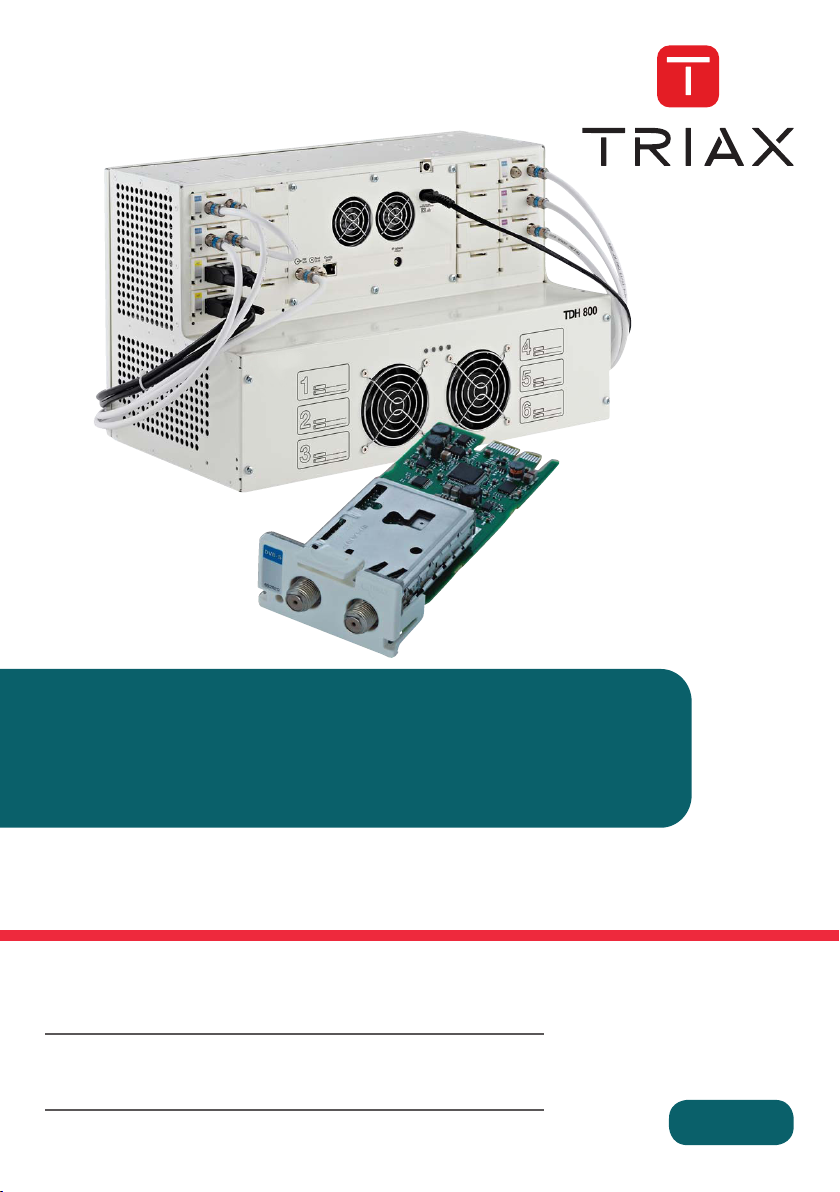
TDH 800 DVB-S/S2 Module
Model Item no.
TDH 800 DVB-S/S2 Module 692820
Version 891573A 08 - 2013 EN
triax.com
Page 2

Contents
Introduction
3
Introduction
This document describes the configuration of the DVB-S/S2 Input
module for the TDH 800 headend.
Physical installation of the module is described in the TDH 800 main unit
installation guide.
System requirements
Computer minimum
requirements
A computer meeting the following minimum requirements is required for
configuring the headend.
Operating system Windows XP or above
Browser Windows Internet Explorer version 6.0 or
equivalent
Additional
software
Microsoft© Silverlight Runtime version 3.0 or
above
Static IP address
A static address must be used on the computer used to configure the
headend.
Refer to the computer’s operating software documentation for
assistance on configuring static IP addresses.
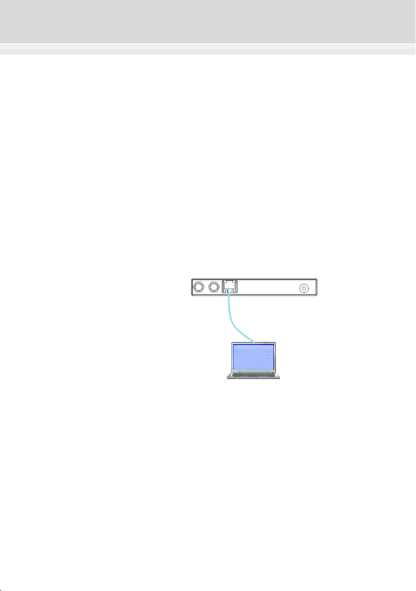
Physical connection to
headend
Connect a Cat5e shielded cable or better between the computer’s
network port and the configuration port on the headend.
Contents
Introduction....................................................................................................................................................... 3
System requirements ....................................................................................................................................... 3
Computer minimum requirements ............................................................................................................. 3
Static IP address ....................................................................................................................................... 3
Physical connection to headend ............................................................................................................... 3
Service tool ....................................................................................................................................................... 4
Overview ....................................................................................................................................................... 5
Icons.......................................................................................................................................................... 5
Tabs .......................................................................................................................................................... 6
Misc. Buttons ............................................................................................................................................. 6
Configuring DVB-S/S2 input modules .............................................................................................................. 7
Pre-requisites ............................................................................................................................................ 7
Configuration ............................................................................................................................................. 7
Advanced settings ................................................................................................................................... 10
Modifying ................................................................................................................................................. 11
Deleting ................................................................................................................................................... 12
Modifying ................................................................................................................................................. 14
Deleting ................................................................................................................................................... 14
2
Page 3
Introduction
Introduction
This document describes the configuration of the DVB-S/S2 Input
System requirements
Computer minimum
requirements
Static IP address
Physical connection to
headend
module for the TDH 800 headend.
Physical installation of the module is described in the TDH 800 main unit
installation guide.
A computer meeting the following minimum requirements is required for
configuring the headend.
Operating system Windows XP or above
Browser Windows Internet Explorer version 6.0 or
Additional
software
A static address must be used on the computer used to configure the
headend.
Refer to the computer’s operating software documentation for
assistance on configuring static IP addresses.
equivalent
Microsoft© Silverlight Runtime version 3.0 or
above
Connect a Cat5e shielded cable or better between the computer’s
network port and the configuration port on the headend.
3
Page 4
Introduction
Introduction
5
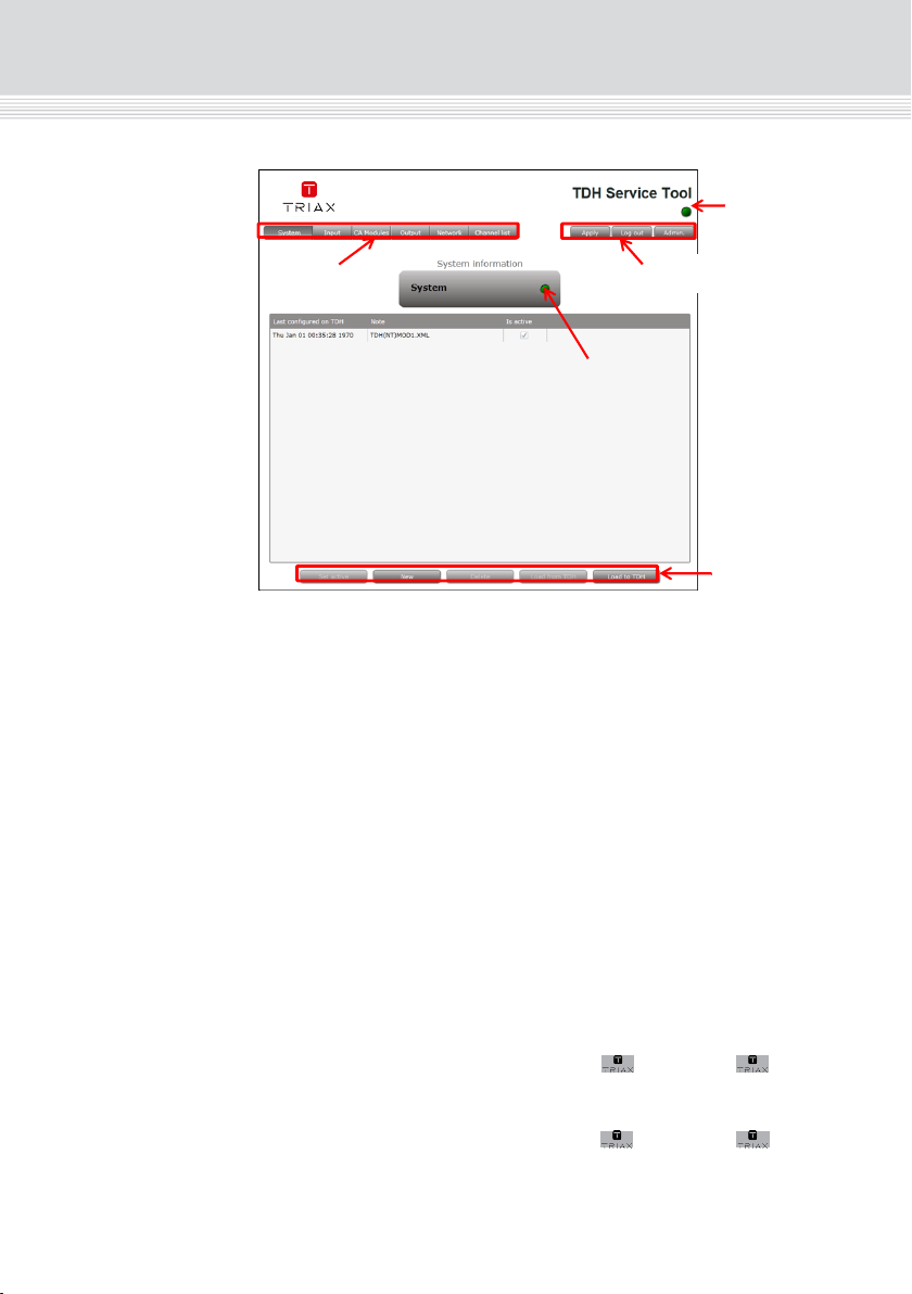
Overview
Icons
Indicates whether the service tool is communicating correctly with the
headend unit.
Green
The service tool and headend are communicating
correctly.
Red
The service tool and headend are NOT communicating
correctly.
Indicates whether the headend unit is functioning correctly.
Green
The headend unit is functioning correctly.
Red
The headend unit is functioning correctly.
Communication
icon
System icon
Configuration
buttons
Tab
Misc.
Service tool
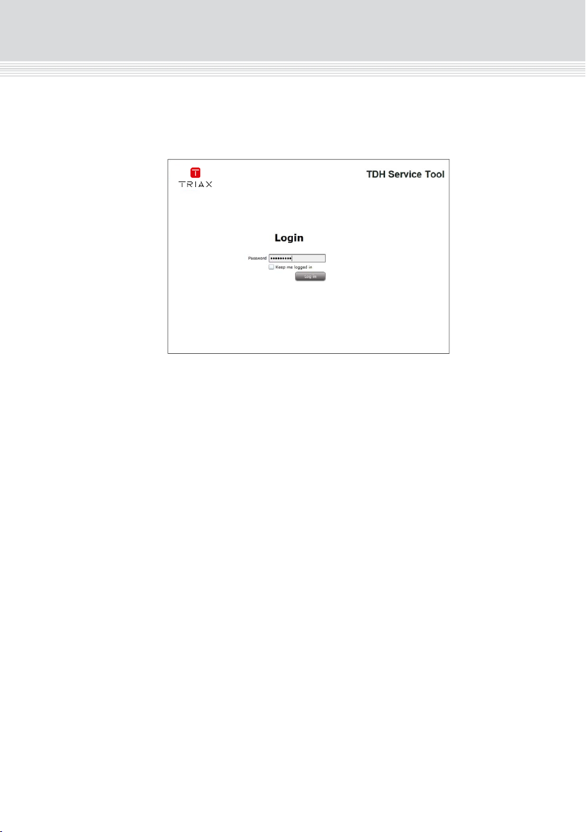
4. Enter the password.
1. Open a web browser window.
2. Enter ‘http://192.168.0.100’ in the web address field.
3. Press Enter.
5. Press the Log in button.
Note:
Password = ‘triax1234’ when the service tool is opened for the first time.
The Keep me logged in checkbox overrides the system’s automatic
time out function, which is activated after 20 minute’s inactivity.
4
Page 5
Introduction
Overview
Tab
System icon
Icons
Indicates whether the headend unit is functioning correctly.
Indicates whether the service tool is communicating correctly with the
headend unit.
Green
Red
Green
Red
The service tool and headend are communicating
correctly.
The service tool and headend are NOT communicating
correctly.
The headend unit is functioning correctly.
The headend unit is functioning correctly.
Misc.
Configuration
buttons
Communication
icon
5
Page 6

Introduction
Configuration
7
Configuring DVB-S/S2 input modules
Pre-requisites
The headend is running, the input module is in position, and the TDH
Service Tool is connected to the headend.
See the TDH 800 Headend User Guide for information on inserting the
input module into the TDH 800 headend.
Configuration
1. Select the Input tab in the TDH Service Tool.
2. Press the Setup button of the input module to be configured.
Tabs
Misc. Buttons
Accesses the various tabs used to configure the headend’s input and
output modules.
System
Input
CA Modules
Output
Network
Channel
List
Apply
Log In/Out
Admin.- Opens the settings for service tool window, where
The service tool’s ‘home’ window. Provides system
overview information and configuration
activation/control.
Tab for configuring input modules and services.
Refer to input module manuals for information.
Tab for configuring CI modules and CA cards.
Refer to output module manuals for information.
Tab for configuring output modules and services. Refer
to output module manuals for information.
Tab for defining customer specific settings that are
network related, e.g. Network name, ID, and for defining
HD/SD channel numbering.
Tab for viewing the channels being transmitted from the
headend, as defined in the Input, CA Modules and
Output tabs. Refer to input module manuals for
information.
Stores configuration settings on the SD card located in
the headend.
Button colour
Red There are changes that have not been stored
Grey All changes are stored on the headend’s SD
Service tool access control.
language, location, time zone, and initial IP addresses
are specified.
on the headend’s SD card.
card.
6
Page 7

Configuring DVB-S/S2 input modules
Configuration
Pre-requisites
Configuration
2. Press the Setup button of the input module to be configured.
The headend is running, the input module is in position, and the TDH
Service Tool is connected to the headend.
See the TDH 800 Headend User Guide for information on inserting the
input module into the TDH 800 headend.
1. Select the Input tab in the TDH Service Tool.
7
Page 8

Configuration
Configuration
9
* The DiSEqC settings button is activated when this polarity type is
selected, See Specifying DiSEqC settings below
Note that ‘0V Off’ must be selected on a DVB-S input module if it
receives signals via another DVB-S input module, i.e. the signal is
‘Looped’.
5. Specify the relevant Symbol rate.
6. Select the relevant LNB setting. Additional input fields are
displayed if ‘Advanced’ is selected, see Specifying advanced LNB
settings below.
7. Press the Update button.
The services list area is populated with the services that can be
delivered from the input module.
8. Press the All button to make all the services in the services list area
available in the TDH pool, or, alternatively select individual services
by checking the relevant check box.
9. Press the Submit button.
10. View the status information at the bottom of the page to check that
the input module is functioning correctly:
Field Contents
Status Whether the input module is locked or not.
Bit error rate The rate at which errors occur in the
transmission.
Locked frequency Displays the actual frequency that the input
module is locked onto.
Apply
Tabs
Input module info
Configuration fields
Advanced
configuration fields
DiSEqC
Multiservice
selection
Service list area
Update button
Reset input button
Status area
Default values are displayed when the configuration tab is opened for
3. Enter the relevant Frequency.
the first time. Note also that the service list area is empty.
4. Select the relevant Polarity, the options are:
0V Off (default)
13V Vertical*
18V Horizontal*
Submit button
8
Page 9

* The DiSEqC settings button is activated when this polarity type is
selected, See Specifying DiSEqC settings below
Note that ‘0V Off’ must be selected on a DVB-S input module if it
receives signals via another DVB-S input module, i.e. the signal is
‘Looped’.
5. Specify the relevant Symbol rate.
6. Select the relevant LNB setting. Additional input fields are
displayed if ‘Advanced’ is selected, see Specifying advanced LNB
settings below.
7. Press the Update button.
Configuration
The services list area is populated with the services that can be
10. View the status information at the bottom of the page to check that
delivered from the input module.
8. Press the All button to make all the services in the services list area
available in the TDH pool, or, alternatively select individual services
by checking the relevant check box.
9. Press the Submit button.
the input module is functioning correctly:
Field Contents
Status Whether the input module is locked or not.
Bit error rate The rate at which errors occur in the
transmission.
Locked frequency Displays the actual frequency that the input
module is locked onto.
9
Page 10

Configuration
Configuration
11
The DiSEqC settings are disabled by default.
2. Select the Enable DiSEqC version 1.0 radio button to specify the
required settings.
3. Select the required Satellite position.
4. Check the Use extended position/polarity checkbox to enable 16
positions if the DiSEqC) switch does not support vertical (13
volts)/horizontal (18 volts) polarisation and High Band/Low Band
frequencies.
5. Press OK to save the specified settings and to return to the
Configuration window.
6. Press the Update button.
Modifying
1. Press the Setup button for the input module to be modified.
2. Make the desired changes.
3. Press the Update button.
4. Press the Submit button.
5. Press the Apply button in the Configuration window
Advanced settings
TS symbol rate Displays the actual symbol rate.
Input TS Rate Displays the how much data the transport
stream (TS) of the input module delivers to
the TDH 800 system.
Input TS Lock Displays the how much data the transport
stream (TS) of the input module delivers to
the TDH 800 system.
Mapped TS Rate Displays how much data is mapped to the
output modules from the corresponding
input.
SW revision Displays the software version of the input
module.
The software version displayed must be
identical with that installed on the TDH
800 main unit and on all other
input/output modules.
Update the software for the entire TDH
800 headend (including input/output
modules) if this is not the case.
LNB settings Additional input fields are displayed when ‘Advanced’ is selected in the
DiSEqC settings It is necessary to select a satellite position if a Digital Sequence
LNB settings drop-down list.
1. Select the required Satellite band.
2. Select the required LNB type.
3. Specify the relevant LOF low, LOF high and LOF switch
parameters.
Equipment Control (DiSEqC) switch is installed.
1. Press the DiSEqC settings button.
Note that the DiSEqC settings button is only active if ‘13V Vertical’ or
‘18V Horizontal’ is selected in the Polarity drop-down list.
10
Page 11

Configuration
The DiSEqC settings are disabled by default.
2. Select the Enable DiSEqC version 1.0 radio button to specify the
required settings.
3. Select the required Satellite position.
4. Check the Use extended position/polarity checkbox to enable 16
positions if the DiSEqC) switch does not support vertical (13
volts)/horizontal (18 volts) polarisation and High Band/Low Band
frequencies.
5. Press OK to save the specified settings and to return to the
Configuration window.
6. Press the Update button.
Modifying
1. Press the Setup button for the input module to be modified.
2. Make the desired changes.
3. Press the Update button.
4. Press the Submit button.
5. Press the Apply button in the Configuration window
11
Page 12

Configuration
Configuration
13
5. Press the Apply button.
The following confirmation is displayed.
And the two services that were selected are visible in the Channel list
tab.
Deleting
1. Press the Delete button of the input module to be removed.
A confirmation popup is displayed.
2. Press Yes to remove the input module.
The input module is displayed in red in the Input tab.
Completion 4. Press the Submit button.
3. Turn off the headend.
4. Physically remove the input module from the headend.
5. Restart the headend.
6. Restart the service tool.
The input module will no longer be listed in the input module list.
The output module’s first slot is now successfully configured, as shown
below.
12
Page 13

5. Press the Apply button.
The following confirmation is displayed.
Configuration
And the two services that were selected are visible in the Channel list
tab.
13
Page 14

Configuration
The remaining slots on the output module can now be configured in the
Modifying
Deleting
2. Press Yes to remove the output module.
The output module is displayed in red in the Output tab.
same manner.
1. Press the Setup button for the output module to be modified.
2. Make the desired changes.
3. Press the Update button.
4. Press the Submit button.
5. Press the Apply button in the Configuration window
1. Press the Delete button of the output module to be removed.
A confirmation popup is displayed.
3. Turn off the headend.
4. Physically remove the output module from the headend.
5. Restart the headend.
6. Restart the service tool.
The output module will no longer be listed in the input module list.
14
Page 15

Manufacturer
Dear Customer
Should you require technical assistance in the event that your expert dealer is unable to help you,
please contact us at:
Triax A/S
Bjørnkærvej 3
8783 Hornsyld
Denmark
Tel.: +45 76 82 22 00
mail: triax@triax.dk
web: www.triax.dk
Manufacturer
Dear Customer
Should you require technical assistance in the event that your expert dealer is unable to help you,
please contact us at:
Triax A/S
Bjørnkærvej 3
8783 Hornsyld
Tel.: +45 76 82 22 00
mail: triax@triax.dk
web: www.triax.dk
Denmark
DECLARATION OF CONFORMITY
TRIAX confirms that the product conforms to relevant EEC harmonised standards and
consequently can carry the CE-mark.
Relevant harmonised standards:
DE/EN 60728-2 2010, DS/EN 60728-11 2010 and DS/EN 50083-2 2006
This document is only valid with the signature of the person responsible for CE-marking by
Triax
Date: October 2012 Signature:
triax.com/support
Copyright © 2016 TRIAX. All rights reserved. The TRIAX Logo and TRIAX, TRIAX Multimedia
are registered trademarks or trademarks of the TRIAX Company or its afliates.
All specications in this guide are subject to change without further notice.
TRIAX A/S | Bjørnkærvej 3 | DK-8783 Hornsyld | Denmark
 Loading...