

Page 1

TW100-W2
NWay Web Cruiser
User’s Guide
Rev. 01 (June, 1998)
6ETH602H.01
Printed In Taiwan
RECYCLABLE
Page 2

Wichtige Sicherheitshinweise
1. Bitte lesen Sie sich diese Hinweise sorgfältig durch.
2. Heben Sie diese Anleitung für den spätern Gebrauch auf.
3. Vor jedem Reinigen ist das Gerät vom Stromnetz zu trennen. Vervenden Sie keine
Flüssig- oder Aerosolreiniger. Am besten dient ein angefeuchtetes Tuch zur Reinigung.
4. Um eine Beschädigung des Gerätes zu vermeiden sollten Sie nur Zubehörteile verwenden,
die vom Hersteller zugelassen sind.
5. Das Gerät is vor Feuchtigkeit zu schützen.
6. Bei der Aufstellung des Gerätes ist auf sichern Stand zu achten. Ein Kippen oder Fallen
könnte Verletzungen hervorrufen. Verwenden Sie nur sichere Standorte und beachten Sie
die Aufstellhinweise des Herstellers.
7. Die Belüftungsöffnungen dienen zur Luftzirkulation die das Gerät vor Überhitzung
schützt. Sorgen Sie dafür, daß diese Öffnungen nicht abgedeckt werden.
8. Beachten Sie beim Anschluß an das Stromnetz die Anschlußwerte.
9. Die Netzanschlußsteckdose muß aus Gründen der elektrischen Sicherheit einen
Schutzleiterkontakt haben.
10. Verlegen Sie die Netzanschlußleitung so, daß niemand darüber fallen kann. Es sollete
auch nichts auf der Leitung abgestellt werden.
11. Alle Hinweise und Warnungen die sich am Geräten befinden sind zu beachten.
12. Wird das Gerät über einen längeren Zeitraum nicht benutzt, sollten Sie es vom Stromnetz
trennen. Somit wird im Falle einer Überspannung eine Beschädigung vermieden.
13. Durch die Lüftungsöffnungen dürfen niemals Gegenstände oder Flüssigkeiten in das Gerät
gelangen. Dies könnte einen Brand bzw. Elektrischen Schlag auslösen.
14. Öffnen Sie niemals das Gerät. Das Gerät darf aus Gründen der elektrischen Sicherheit
nur von authorisiertem Servicepersonal geöffnet werden.
15. Wenn folgende Situationen auftreten ist das Gerät vom Stromnetz zu trennen und von
einer qualifizierten Servicestelle zu überprüfen:
a– Netzkabel oder Netzstecker sint beschädigt.
b– Flüssigkeit ist in das Gerät eingedrungen.
c– Das Gerät war Feuchtigkeit ausgesetzt.
d– Wenn das Gerät nicht der Bedienungsanleitung ensprechend funktioniert oder Sie mit
Hilfe dieser Anleitung keine Verbesserung erzielen.
e– Das Gerät ist gefallen und/oder das Gehäuse ist beschädigt.
f– Wenn das Gerät deutliche Anzeichen eines Defektes aufweist.
16. Bei Reparaturen dürfen nur Orginalersatzteile bzw. den Orginalteilen entsprechende Teile
verwendet werden. Der Einsatz von ungeeigneten Ersatzteilen kann eine weitere
Beschädigung hervorrufen.
17. Wenden Sie sich mit allen Fragen die Service und Repartur betreffen an Ihren
Servicepartner. Somit stellen Sie die Betriebssicherheit des Gerätes sicher.
ii
Page 3

Quick Installation
This section takes you through a step-by-step minimum installation and setup procedure for the internet server. Please refer to
the main text of this manual for detailed information about the
setup and operation of this device.
Getting Started
Step 1: Unpack the device. Make certain no components have
been lost or damaged. A packing list is provided on page 5.
Step 2: Choose an installation site on a flat, level surface or wall
near the modem or ISDN/TA you plan to use for internet
connections or near the network line you plan to use for a
LAN connection. Note that the internet server can be hung
on a wall using the wall mounting equipment included
with the product.
Making Connections
Step 3: Connect the internet server to your LAN using a Cate-
gory 3, 4 or 5, twisted-pair cable and the device’s single RJ45 LAN port. This connection should be made to an
Ethernet or Fast Ethernet switch or hub. (The RJ-45 port
looks like a phone jack.)
Step 4: Connect the internet server to a modem or ISDN/TA, us-
ing one or both of the device’s serial ports (COM1 and
COM2). (Note that your modem or ISDN/TA should already be connected and setup according to the instructions
included with it.)
Step 5: Plug the power adapter into the device and into an out-
let.
iii
Page 4

Configuring
Step 6: Before your can use your internet server, IP addresses on
your LAN’s PCs must be set so that they are compatible
with the internet server’s settings. The internet server
comes with the default local IP address: 192.168.100.1
the default subnet mask setting: 255.255.255.0
stations on your LAN that will use the internet server for
internet access must modify their IP settings to
192.168.100.xxx (where xxx is a number between 2 and
255). All stations must also modify their subnet mask settings to match the internet server subnet mask setting,
and set their default gateway to the local IP address (in
this case the default address listed above) used by the
internet server. If you want to use a different IP address
range, see “Setting IP Addresses” on page 12.
. Computer
Step 7: The internet server can be configured and operated via
Telnet or a web browser once PC IP addresses have been
properly set. (Note that some device settings can be manipulated using the IS Admin program included with the
device.) Start your Telnet or browser software and enter
the IP address of the internet server (either the default IP
listed above or the new address you assigned using IS
Admin). This should bring up the internet server start
menu. See the next series of steps for information about
variables that must be set for the device to work properly.
and
Key Variables
Step 8: ISP Account -> Phone Number, when you signed-up
for an account with your ISP (internet service provider),
you should have been given an access phone number that
your modem will dial. Look under the “WAN Port Variables” menu for this variable and enter the phone number
provider by your ISP.
iv
Page 5

Step 9: ISP Account -> User ID, your ISP should also have as-
signed a User ID (aka, a username) that you will use for
logging-in. Also under “WAN Port Variables,” enter this
user ID exactly as it was provided to you.
Step 10: ISP Account -> Password, finally, to complete the
ISP login process, the internet server must provide the
password associated with the user ID assigned by your
ISP. Enter it.
You have now completed the basic steps necessary to install, configure, and begin using the internet server. Note that, with
respect to steps 8–10, it may be necessary for you to use a “Login
Script” instead. If you enter the information required in those
three variables correctly and still have trouble logging-in, see the
“Login Script” section on page 19 to create a login script.
v
Page 6

Trademarks
Contents subject to change without prior notice.
All trademarks belong to their respective proprietors.
Copyright Statement
No part of this publication may be reproduced in any form or by
any means or used to make any derivative such as translation,
transformation, or adaptation without permission from the manufacturer, as stipulated by the United States Copyright Act of 1976.
FCC Warning
This equipment has been tested and found to comply with the limits for a Class A digital device, pursuant to Part 15 of the FCC
Rules. These limits are designed to provide reasonable protection
against harmful interference when the equipment is operated in a
commercial environment. This equipment generates, uses, and
can radiate radio frequency energy and, if not installed and used in
accordance with this user’s guide, may cause harmful interference
to radio communications. Operation of this equipment in a residential area is likely to cause harmful interference in which case
the user will be required to correct the interference at his own expense.
CE Mark Warning
This is a Class A product. In a domestic environment, this product
may cause radio interference in which case the user may be required to take adequate measures.
VCCI A Warning
vi
Page 7

TABLE OF CONTENTS
QUICK INSTALLATION ......................................................... III
0ABOUT THIS GUIDE .......................................................... XI
Audience ........................................................................................xi
Overview of the User’s Guide........................................................xi
1CHAPTER 1 : INTRODUCTION..............................................1
Product Description .......................................................................1
Product Features ............................................................................1
Internet Server Technology ............................................................2
2CHAPTER 2 : INSTALLATION............................................... 5
Unpacking ......................................................................................5
Desktop / Shelf Installation..........................................................6
Wall Installation ............................................................................6
Port Description..............................................................................7
Serial – WAN .........................................................................................7
RJ-45 – LAN ..........................................................................................8
LED Description.............................................................................8
Pw/Tx .....................................................................................................8
Link/Rx................................................................................................... 8
COM1 / COM2........................................................................................8
Normal LED Flash Pattern................................................................... 9
Page 8

Internet Server User’s Guide
Connecting to the Local Network ..................................................9
Connecting to the Internet ...........................................................10
Connecting Power.........................................................................10
3CHAPTER 3 : SYSTEM SETUP........................................... 11
Setting IP Addresses ....................................................................12
Default Addressing.............................................................................. 12
Configuring LAN IP Addresses........................................................... 12
Using In-Band Telnet to Configure the Server...........................14
Using a Browser to Configure the Server....................................14
Minimum Configuration .............................................................15
DNS IP Address...................................................................................16
ISP Account -> Phone Number ...........................................................16
ISP Account -> User ID ....................................................................... 17
ISP Account -> Password ....................................................................18
Login Script..........................................................................................19
Operation ......................................................................................20
4CHAPTER 4 : CONFIGURATION VARIABLES........................ 21
System Variables..........................................................................21
Server Name ........................................................................................21
Local LAN -> IP Address..................................................................... 22
Local LAN -> Subnet Mask................................................................. 22
DNS IP Address...................................................................................23
Maximum Idle Time ............................................................................ 23
Operation Mode ...................................................................................24
Change Password ................................................................................25
WAN Port (1 & 2) Variables ........................................................25
Maximum User Connection.................................................................25
Line Type .............................................................................................26
Baud Rate ............................................................................................26
ISP Account -> Phone Number ...........................................................26
ISP Account -> User ID ....................................................................... 27
viii
Page 9

ISP Account -> Password ....................................................................27
ISP Account -> IP Address ................................................................. 27
Modem AT Command.......................................................................... 28
Login Script..........................................................................................29
DHCP Server Variables ...............................................................30
Enable ..................................................................................................30
IP Address Range -> Start ..................................................................31
IP Address Range -> End ....................................................................31
IP Lease Time ......................................................................................32
IP Reserve Table..................................................................................32
Server Address Variables.............................................................32
System Monitoring .......................................................................34
Displaying Information .......................................................................34
Tools .....................................................................................................35
Navigation Controls.....................................................................36
5APPENDIX A : TROUBLESHOOTING ................................... 37
System POST................................................................................37
Device Installation Problems.......................................................38
WAN..................................................................................................... 38
LAN ......................................................................................................39
Station Configuration Problems .................................................39
Operating Problems .....................................................................39
6APPENDIX B : SPECIFICATIONS ........................................41
General..........................................................................................41
Environmental and Physical.......................................................42
7APPENDIX C : AT COMMANDS .........................................43
Basic AT Command Set...............................................................43
ix
Page 10

Internet Server User’s Guide
Extended AT& Command Set .....................................................47
8APPENDIX D : PORT PINOUTS ..........................................49
Serial Ports...................................................................................49
RJ-45 Port ....................................................................................50
9APPENDIX E : GLOSSARY ................................................51
I
NDEX ............................................................................... 56
x
Page 11

0 ABOUT THIS GUIDE
This guide explains how to install and use the internet server.
Audience
This manual assumes basic familiarity with LANs, the internet,
and ISPs. It has, however, been designed for basic-level users.
Overview of the User’s Guide
♦ Chapter 1, Introduction. Provides information on the inter-
net server and internet server technology.
♦ Chapter 2, Installation. Helps you unpack, understand and
install the internet server.
♦ Chapter 3, System Setup. Explains how to set necessary op-
tions on the internet server.
♦ Chapter 4 Configuration Variables. Explains all available
variables on the internet server and what options exist for
configuration and use.
♦ Appendix A, Troubleshooting. Provides direction and assis-
tance for locating the source of problems and solving them.
♦ Appendix B, Specifications. Lists the device’s specifications.
Page 12

Internet Server User’s Guide
xii
♦ Appendix C, AT Commands. Lists the basic and extended
AT command sets.
♦ Appendix D, Port Pinouts. Provides pinout data for the de-
vice’s ports.
♦ Appendix E, Glossary. Provides the meaning for some net-
working terms used in this manual.
About This Guide
Page 13

1
1 INTRODUCTION
This chapter introduces the internet server, as well as some of the
technology that underlies it.
Product Description
The internet server is designed to provide a single-point access to
the internet for multiple, networked PCs. One of the primary features of the internet server is that it provides multi-user access to
the internet through a single user account and one connection.
More simply put, an internet server takes a single internet connection that without it could only be used by one person and
allows it to be used by multiple stations on the same network simultaneously.
Product Features
The list below highlights the features and specifications of the
internet server.
♦ Compatible with the IEEE 802.3 10BASE-T Ethernet and
802.3u 100BASE-TX Fast Ethernet industry standards for
Introduction
1
Page 14
Internet Server User’s Guide
interoperability with other Ethernet/Fast Ethernet network
devices.
♦ Internet protocol support for: PPP, PAP/CHAP, NAT,
TCP/IP, DHCP, ARP, ICMP, SMTP, POP3, FTP, Telnet, and
HTTP.
♦ Support for device configuration via Telnet, web browser,
and IS Admin program (included).
♦ NWay TP port for LAN connection.
♦ Ethernet connections support Category 3 or better twisted-
pair cables.
♦ Fast Ethernet connections support both shielded twisted
pair and Category 5 unshielded twisted-pair cables.
♦ 56K (maximum) modem speed support
♦ 128K (maximum) ISDN/TA speed support
♦ Internet Features include: Dial-On-Demand, NAT internet
access, DHCP server, and virtual server.
♦ Flash memory for easy firmware upgrades.
Internet Server Technology
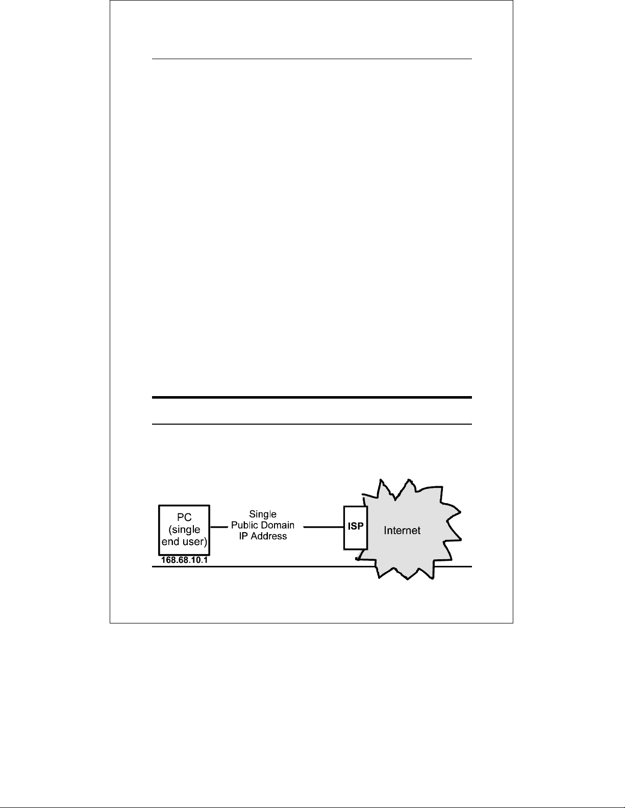
The concept behind internet servers is to provide a single, shared
access point for multiple users. Without an internet server, each
end point (i.e., PC or workstation) on a LAN must have it’s own
Introduction
2
Page 15
public domain IP address.
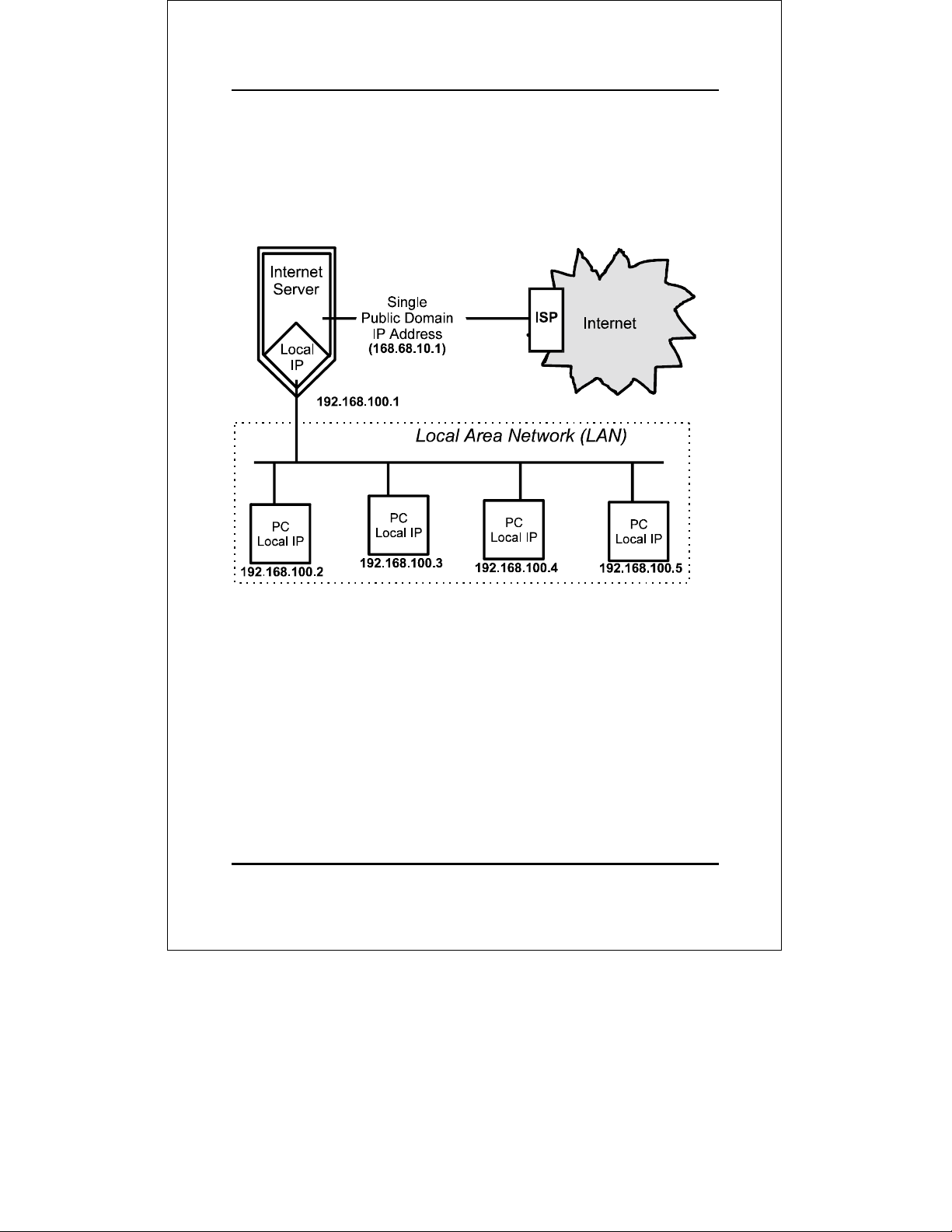
Using an internet server allows a single public IP address to be
shared by multiple local end points simultaneously.
Since the same range of local IP addresses can be used at as many
multiple locations as necessary, available IP addresses can increase. Also, it is only necessary for a company to pay for a single
internet access account even though many people will be able to
use it.
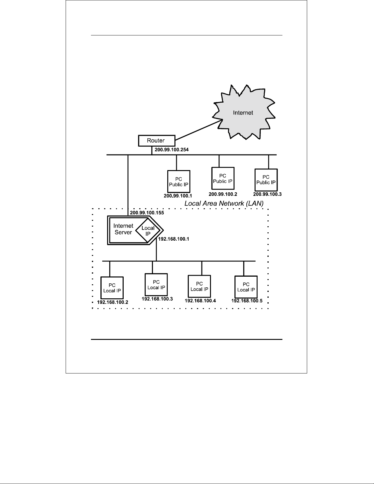
An internet server can also be used to expand a LAN by providing
a means to create localized “sub-groups” in a LAN-to-LAN configuration. The internet server acts as a single public IP address
access point for the sub-group LAN. The sub-group LAN can then
use local IP addresses from the available ranges. The effect of this
Introduction
3
Page 16
Internet Server User’s Guide
is to expand the number of stations that can use IP addresses assigned to the LAN.
Introduction
4
Page 17

2
2 INSTALLATION
This chapter provides information on the unpacking and initial
installation of your internet server.
Unpacking
Open the shipping carton of your internet server and carefully unpack the contents. The carton should contain the following items:
♦ One internet server device
♦ One AC power adapter, suitable for your area’s electrical
power connections
♦ One 3.5” diskette with IS Admin software
♦ IS Admin User’s Guide
♦ Wall mount hardware
♦ This User’s Guide
Inspect the device and all accompanying items. If any item is
damaged or missing, report the problem immediately to your
dealer.
Installation
5
Page 18

Internet Server User’s Guide
Desktop / Shelf Installation
The unit has rubber feet attached to the bottom to cushion it. Allow enough ventilation space between the device and the objects
around it. Choose a sturdy, level surface in a ventilated area that
is dust free and away from heat vents, warm air exhaust from
other devices and direct sunlight. Avoid proximity to large electric
motors or other electromagnetic equipment.
Observe the following guidelines when choosing an installation
location:
• Air temperature should range from 32° to 122° F (0° to 50° C).
• Humidity should be less than 90%, non-condensing.
• Site should not exceed the electromagnetic field (RFC) stan-
dards for IEC 801-3, Level 2 (3V/M) field strength.
For a detailed list of the product’s technical specifications, refer to
Appendix B, Specifications.
Wall Installation
The product can be installed on a wall. When installing, you need
to attach two tapping screws and two screw anchors to the bottom
of the device. Wall mount supplies are included with the device.
Installation
6
Page 19
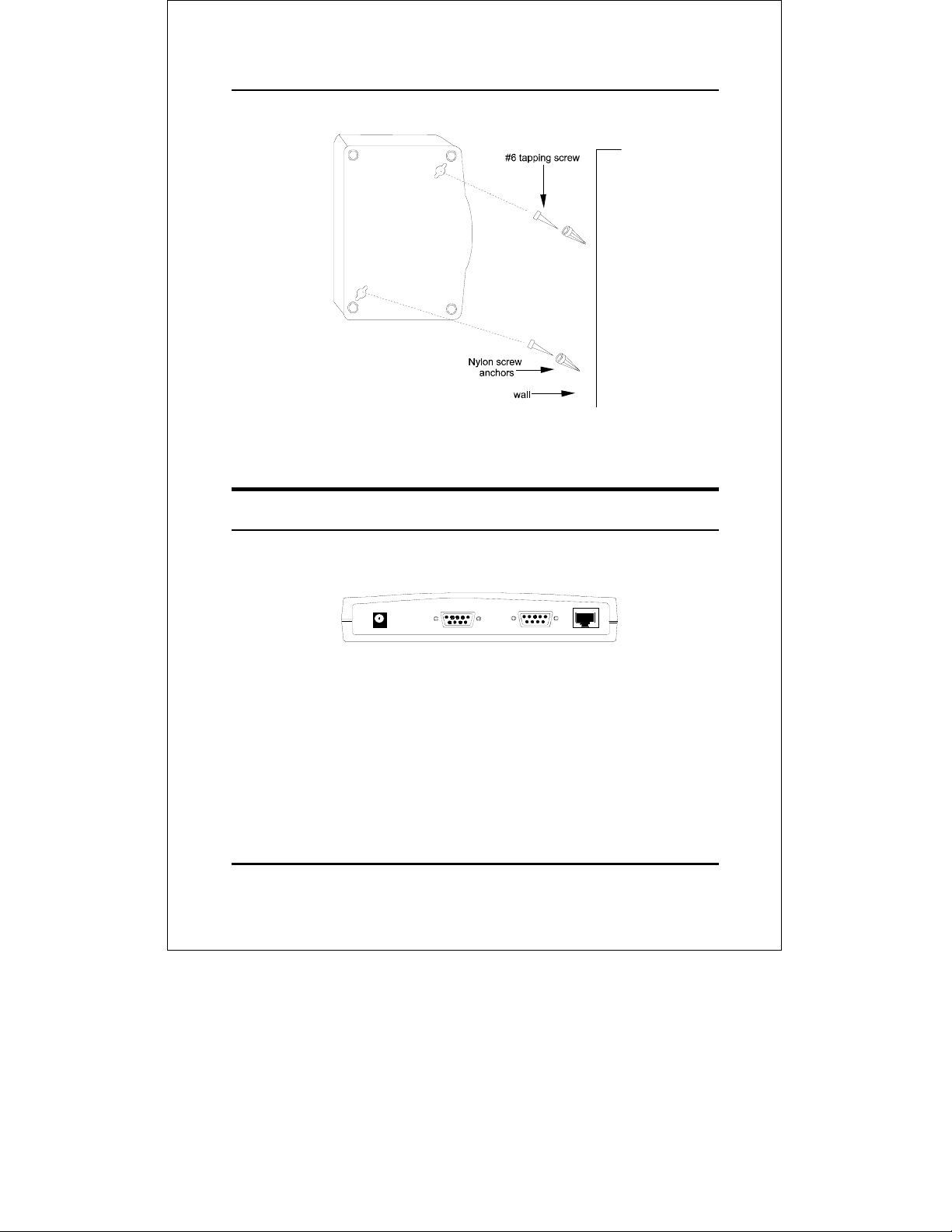
Installing the Internet Server on a Wall
Port Description
The internet server has two WAN ports.
Internet Server Rear Panel
Serial – WAN
Serial ports are used for WAN connections either to a modem or an
ISDN terminal adapter. Both serial ports are standard male 9-pin
RS-232 connectors.
Installation
7
Page 20

Internet Server User’s Guide
RJ-45 – LAN
The internet server has a single, NWay RJ-45 LAN port. This port
is 10Mbps and 100Mbps capable (auto-detect, auto-configure) and
designed for use in an Ethernet or Fast Ethernet LAN via a network hub. The port has standard RJ-45 pinouts.
LED Description
The internet server has a small LED array for indicating current
port and transmission status. The power/transmit (Pw/Tx) and
connect/receive (Link/Rx) LEDs only relate to activity on the LAN
ports. All other LED indicators display information about their
related ports as labeled.
Pw/Tx
The Pw/Tx (power/transmit) LED lights when power is supplied to
the device and flashes when a LAN port transmits data.
Link/Rx
The Link/Rx (link/receive) indicator will light up when a good connection is made at either LAN port with an operating and
compatible Ethernet or Fast Ethernet device. This indicator
flashes when either LAN port receives data from the network.
COM1 / COM2
Each COM port LED provides an indication of the operating status
of one WAN port. When a WAN port is transmitting data, the re-
Installation
8
Page 21

lated COM port will light. If no data is being transmitted, the
COM LEDs will be off.
Normal LED Flash Pattern
Immediately after power-up, all four of the LEDs should display
steady green for several seconds. Then both COM LEDs should
flash simultaneously three times. This sequence of flashes should
be followed by first COM1 flashing once and then COM2 flashing
once, repeated three times in succession. If as problem with the
device is detected during this time, the LED flashes will display an
error pattern (see Appendix A: Troubleshooting for more information on POST error indications). If no errors are detected, the
internet server will begin operating normally.
Connecting to the Local Network
The internet server includes one RJ-45 NWay LAN port. To
connect the device to your LAN, use a standard Category 3, 4,
5 UTP, or STP twisted-pair cable to link the device to an
Ethernet or Fast Ethernet hub or switch.
Cable length limits must conform to Ethernet and Fast
Ethernet wiring rules. Ethernet cable segments can be a
maximum of 100 meters. Fast Ethernet wiring rules also limit
the maximum length of cabling segments to 100 meters.
Once the internet server is physically connected to a local network and you have used the IS Admin software included to
assign an IP address to the device (or simply reconfigured your
PC’s IP address, subnet mask and gateway to match the default
settings of the internet server), you may configure other parameter variables from your network station using Telnet or a
web browser.
Installation
9
Page 22

Internet Server User’s Guide
Connecting to the Internet
The internet server must be connected to the internet (this is also
known as a “Wide Area Network or ‘WAN’” connection) using a
COM serial port. A COM port can either be connected to the serial
port of a modem (or fax/modem), or to an ISDN terminal adapter.
This internet server model has two COM ports and can therefore
have two WAN connections. Any combination of different types of
WAN connections will work. The faster the WAN connections are,
the faster access will be and the more users will be able to get on
the internet simultaneously.
Connect the COM port of the internet server to a modem or ISDN
terminal adapter using a standard serial cable.
Connecting Power
Power is supplied to the internet server through an AC power
adapter. Check the technical specifications section for information
about the AC power input voltage.
Since the internet server does not include a power switch, plugging its power adapter into a power outlet will immediately power
it on.
Installation
10
Page 23

3
3 SYSTEM SETUP
Before it can be used, the internet server has some variables that
need to be properly set. This chapter describes how to change default IP settings and then how to use Telnet or a web browser to
manipulate the internet server. A description of the minimum
setup required to operate is also provided. A full listing of all
variables on the internet server is provided in Chapter 4. Note
that the variables and their options are the same regardless of
whether you are using Telnet or a web browser although they are
displayed in different formats.
Usage Note: Throughout this user’s guide, we refer to “your
ISP.” An ISP is a company that provides internet services, normally for a fee, and usually via
modems connected over telephone lines.
From the ISP’s point of view, the internet
server is a single user (with a single username
and password). The purpose of the server is
to allow you to get access as a single user for
multiple actual users.
System Setup
11
Page 24

Internet Server User’s Guide
Setting IP Addresses
The internet server comes with a default IP address and subnet
mask assigned. If you would prefer not to use the internet server’s
default IP address, it will be necessary for you to change that address using the IS Admin program included with the device.
Regardless, it will be necessary for you to configure one PC with
an IP address and subnet mask that are compatible with the settings of the internet server. (Note that your PC’s IP address,
subnet mask, and IP gateway must be hand set; The IS Admin
program does not include this function.)
Once the server and a management PC have compatible IP address and subnet mask settings, and are connected through the
LAN, either an in-band Telnet session or a web browser can be
used to set the device’s configurable variables and view its current
operating status.
Default Addressing
The internet server comes with a preset default IP address setting
of 192.168.100.1. In order to configure the internet server, you
must set at least one computer on your LAN to an IP address in
the same subnet (192.168.xxx.xxx).
Configuring LAN IP Addresses
Before you can use Telnet or a browser to configure the internet
server, it is necessary for you to change your PC’s IP address to
the same subnet as the LAN IP used by the server. Each operating system and network software suite will have a different
procedure/application for setting the system IP.
System Setup
12
Page 25

Under TCP/IP (many Windows 3.1 and 3.11 users), the system IP
and subnet mask are configured under “Setup” in the TCP manager. In Windows 95, users must go to the Control Panel and
Network settings; Under Network settings, you must modify the
TCP/IP properties for the IP address, subnet mask, and default
gateway. The IP address should be on the same subnet as the local address assigned to the internet server, the subnet mask
setting should be the same as the internet server, and the default
gateway setting should be the local IP address assigned to the
internet server.
Since the principle behind internet server technology is the use of
local IP addresses that are never seen or used on public systems,
you must use IP addresses from the ranges below. The following
three IP address blocks have been set aside by internet regulatory
authorities specifically for local-only use:
10.0.0.0 – 10.255.255.255
172.16.0.0 – 172.31.255.255
192.168.0.0 – 192.168.255.255
All local stations using the server to access the internet must have
an IP address within these three ranges, as well as an IP address
on the same subnet as the internet server.
Important: If the server’s IP address is 10.10.1.150, all
local stations must have an IP address as:
10.10.1.xxx, the subnet mask setting must be
the same, and the default gateway of each station needs to be set to the local IP address
assigned to the internet server.
System Setup
13
Page 26

Internet Server User’s Guide
We recommend that you make a note of each device’s IP address
for reference during troubleshooting or when adding new stations
or devices.
Using In-Band Telnet to Configure
the Server
Once your PC is configured with an IP address on the same subnet
as the server, start your Telnet program and enter the IP address
assigned to the server when you are prompted for a host address.
You should immediately see the internet server Telnet Interface
console greeting screen.
Enter the password to access the device parameters. There is no
default password. Once you have access, use the menu item numbers to set the variables which are described later in this chapter.
Note: When using Telnet to modify device parame-
ters, saving those parameters immediately
ends the Telnet session.
Using a Browser to Configure the
Server
Once your PC is configured with an IP address on the same subnet
as the server, start your browser program and enter the “http://”
prefix, followed by the IP address assigned to the server, in the
address window.
System Setup
14
Page 27

You should immediately see the internet server web browser interface menu. Note that the internet server IP can be bookmarked
for future access so that it doesn’t need to be entered each time.
The browser interface uses frames, so it is best if you use a framescapable browser program. Also, we advise you to temporarily suspend the use of proxies – if you are using them – while accessing
the internet server as proxy settings may interfere with browser
access to local devices.
If you use a non-frames browser, when you receive the initial
internet server screen, you should see the main navigation menu
rather than the navigation menu and the system status screen.
The functions are the same, only the appearance will be different.
After you have access to the browser interface, use the menu options in the left-hand frame to choose the variables you want to
view, set or modify. Some variables have limited options that
must be selected from a pull-down list.
Minimum Configuration
Regardless of how you intend to use the internet server, you will
need to consider and set some basic system variables. This section
is concerned with describing only those variables that are critical
to proper functioning of the internet server.
The following variables need to be configured for the internet
server to operate correctly (the first is a System variable, the others are WAN port variables):
System Setup
15
Page 28

Internet Server User’s Guide
DNS IP Address
Domain Name Service (DNS) servers are used on the internet to
maintain information about which Uniform Resource Locator
(URL) name relates to which internet IP address. For example,
the URL: WWW.CNN.COM, is a pseudonym for the IP address:
207.25.71.25. DNS entries allow users to access resources using
URLs instead of IPs.
Options: Any internet DNS server IP address available
through the WAN connection. This address should be provided by your ISP. (Note that without a DNS server IP,
internet sites will only be available using IP addresses and
will not be available using URLs.)
Default Value: 0.0.0.0
Must Be User Modified? Yes.
Description: A Domain Name Service (DNS) server address is
used to translate URLs into their corresponding IP addresses.
ISP Account -> Phone Number
In order for the internet server to control the modem to dial the
phone, you must enter the dial-up phone number for your ISP. If
you need to dial an area code in order to call the number, it must
be included in this variable. If you must dial “#”, 0, 9 or some
other number in order to get an outside phone connection, that
information must be included in how this variable is configured.
Options: For dial-up connections, the local ISP phone
number, complete without spaces, hyphens or other punctuation (commas may be used to indicate a pause). The
maximum length is 20 characters.
System Setup
16
Page 29

Example: Your ISP phone number is a local call to 916-
5555 and you must dial 0 in order to get an outside line from
the office where you want to use the internet server. You
would enter 0,,9165555 in the “ISP Account -> Phone Number” variable. The two commas instruct the modem to pause
between dialing the 0 and dialing the rest of the number.
This pause is necessary if there is normally a moment or two
between dialing 0 and getting an outside dial tone.
Default Value: (none)
Must Be User Modified? Yes.
Description: The phone number entered in this variable is
the number the internet server will dial to establish its
internet (WAN) connection.
Note: If the ISP phone line is busy, the internet
server will automatically redial. Three successive redial attempts will be made.
ISP Account -> User ID
Just as the internet server needs to know what phone number to
dial to access your ISP, it also needs to know what username to
login under. This variable is the username the ISP has assigned
to you or your company.
Options: Needed for dial-up connections. The ISP assigned
user ID name exactly as provided (i.e., all letters capitalized
where necessary, underscores and other punctuation included). The maximum length is 16 characters.
Default Value: (none)
System Setup
17
Page 30

Internet Server User’s Guide
Must Be User Modified? Yes.
Description: This variable is the user ID that will be pro-
vided to the ISP once the modem connection is established.
Notes: It may not be possible with some ISPs to use this
variable to allow the internet server to automatically login.
In that case, it will be necessary to use the Login Script as
described below.
ISP Account -> Password
The password is the final step in the ISP dial-up login process. As
with the username, this password should have been assigned to
you by your ISP when you registered for the service.
Options: For dial-up connections, the ISP user access
password exactly as provided (i.e., all letters capitalized
where necessary, underscores and other punctuation included). The maximum length is 16 characters.
Default Value: (none)
Must Be User Modified? Yes.
Description: This variable is the user password that will
be provided to the ISP once the modem connection is established and the username has been accepted.
Notes: It may not be possible with some ISPs to use this
variable to allow the internet server to automatically login.
In that case, it will be necessary to use the Login Script as
described below.
System Setup
18
Page 31

Login Script
The login script allows you to list prompts generated by the ISP
each time a user dials-up and then provide the right responses so
that the internet server can login. The login script should be used
when the Username and Password variables above don’t work
with your ISP or if your ISP’s login procedure includes additional
prompts (for example, a transmission protocol choice).
Options: For each line item, a prompt string and a keyin
string must be provided. The prompt string is the text displayed by the ISP requesting that something be entered.
The keyin string is what should be entered. Prompt strings
can be up to 25 characters long including punctuation.
Keyin strings can be up to 20 characters long including
punctuation (a maximum of 8 separate line entries).
Example: If your ISP asks you to input a user ID, pass-
word, and to choose from a list of available communications
protocols each time you dial-up, your login script would look
like something like this:
No. Prompt Keyin
1 Username Andy
2 Password abcd
3 Choice --> 2
With each prompt being the text of the prompt provided by
the ISP, and each keyin being the exact data you would enter.
Default Value: (none)
Must Be User Modified? No (unless your ISP login proce-
dure requires you to use a login script).
System Setup
19
Page 32

Internet Server User’s Guide
Description: A login script is used to provide login prompt
responses when required by the ISP login procedures. Each
line item in the script table should correspond with a prompt
that the ISP makes once the modem connection is established. The prompt string information entered in the table
should include an indication of what data is being asked for
at each step in the login process. Reply string data should
be provided exactly as it would be if it were hand entered.
Operation
To access the internet, do the following at each station that will
use the internet server for internet access:
1. Make sure that TCP/IP settings are configured properly. IP
parameters that must be set:
• IP Address – must be a unique IP address chosen from the
three reserved IP ranges set aside for local network only
use. See “Setting IP Addresses” earlier in this chapter.
• Default Gateway – should be set to the IP address as-
signed to the internet server’s LAN interface.
• DNS (Domain Name Service) – an IP address provided
by your ISP.
2. Activate your browser and use normally.
System Setup
20
Page 33

4
4 CONFIGURATION
VARIABLES
This chapter provides information about all of the configuration
settings available on the internet server. Information about the
range of values, default setting, and purpose for each variable is
given. Sections and variable order correspond with the menu listings presented by the internet server Telnet console program.
Note that those variables which must be user configured are further detailed in Chapter 3.
System Variables
Server Name
Options: An fifteen-character string of letters and num-
bers.
Default Value: IS-xxxxxx (where “xxxxxx” is the last six
digits of the device’s MAC address).
Description: The server name is used to identify the
internet server on network management lists of active devices.
Configuration Variables
21
Page 34

Internet Server User’s Guide
Local LAN -> IP Address
The Local LAN IP Address variable defines the unique IP address
that your network will use to identify the internet server.
Options: Any IP address from within the local-only ranges
(10.0.0.0.– 10.255.255.255 ; 172.16.0.0 – 172.31.255.255 ;
192.168.0.0 – 192.168.255.255).
Default Value: 192.168.100.1
Must Be User Modified? No.
Description: The IP address assigned to the internet
server must be consistent with the addresses to be used by
other devices on the network. That is, if the internet server
address is 192.168.100.1, all other addresses assigned to local network devices must start with 192.168.100 and have a
final number between 2 and 255.
Local LAN -> Subnet Mask
This variable defines the subnet level the internet server will
share with other devices on the network.
Options: Any subnet address which identifies a subnet
level.
Default Value: 255.255.255.0
Must Be User Modified? No.
Description: The subnet mask is used to identify sub-
groups on a LAN. A subgroup is a set of network nodes that
can receive broadcast messages (i.e., messages not requiring
a specific IP).
Configuration Variables
22
Page 35

DNS IP Address
Domain Name Service (DNS) servers are used on the internet to
maintain information about which Uniform Resource Locator
(URL) name relates to which internet IP address. For example,
the URL: WWW.CNN.COM, is a pseudonym for the IP address:
207.25.71.25. DNS entries allow users to access resources using
URLs instead of IPs.
Options: Any internet DNS server IP address available
through the WAN connection. This address should be provided by your ISP. (Note that without a DNS server IP,
internet sites will only be available using IP addresses and
will not be available using URLs.)
Default Value: 0.0.0.0
Must Be User Modified? Yes.
Description: A Domain Name Service (DNS) server ad-
dress is used to translate URLs into their corresponding IP
addresses.
Maximum Idle Time
This variable allows you to set an idle time after which the internet server will automatically disconnect the WAN connection.
Setting an idle time lets you keep from staying logged-in to your
ISP when no one is using the internet.
Options: A time duration from 3 to 65535 minutes.
Default Value: 30 minutes
Must Be User Modified? No.
Configuration Variables
23
Page 36

Internet Server User’s Guide
Description: The system will automatically disconnect the
WAN link if the port is inactive for the time set.
Operation Mode
Options (sub-menus):
♦ Mode: LAN-to-WAN / LAN-to-LAN; Default is LAN-
to-WAN operation.
♦ LAN-to-LAN Internet server -> Global IP Ad-
dress: Internet server’s address for the router
segment when used in LAN-to-LAN mode only.
♦ LAN-to-LAN Internet server -> Subnet Mask: (as
subnet mask above)
♦ LAN-to-LAN Internet server -> Default Gateway:
Router’s IP Address.
Default Value: Mode
LAN-to-WAN
=
Description: This option only needs to be changed if the
internet server isn’t going to be used to connect directly to
an ISP. Enabling LAN-to-LAN mode automatically disables
the LAN-to-WAN Internet server and Server Address Mapping functions.
LAN-to-LAN mode should be used when you need to expand
your LAN but have limited IP addresses available and
internet access is provided via a router.
Note: In LAN-to-LAN mode, you cannot let users
outside of the LAN have access to services
(e.g., Telnet, FTP, or web servers).
Configuration Variables
24
Page 37

Change Password
Options: An eight-character string of letters and numbers.
Case sensitive.
Default Value: (none – no password)
Must Be User Modified? No (but it is highly recommend
to protect your internet server’s settings).
Description: Prevents unauthorized access to the device.
WAN Port (1 & 2) Variables
Maximum User Connection
Set this variable to limit the number of users who must access the
internet through the server before new user accesses are directed
to the secondary WAN port.
Options: A number of users between 1 and 255
Default Value: 6
Must Be User Modified? No.
Description: The internet server uses the limitation cre-
ated by this variable to allocate resources in the most
efficient way possible. If the maximum allowed on COM1 by
this variable is reached, the next user who attempts to use
the server will be given access through the secondary WAN
port. If both WAN ports reach the allowed maximum, new
user requests are evenly distributed between the two ports
one-at-a-time. There is no ultimate maximum.
Configuration Variables
25
Page 38

Internet Server User’s Guide
Line Type
Options: Disable, Dialup, Lease Line.
Default Value: Dialup
Description: The WAN port must be configured for use as
either a dial-up connection or a leased-line connection.
Baud Rate
Options: 4800, 9600, 19200, 38400, 57600, 115200, 230400,
460800 bps.
Default Value: 115200 bps
Description: The setting of this variable sets the maxi-
mum bits per second data transmission rate on the line.
Generally, the rate should be set equal to or greater than
the maximum possible transmission rate of the device (e.g.,
the modem) connected to the WAN port.
ISP Account -> Phone Number
Options: For dial-up connections, the local ISP phone
number, complete without spaces, hyphens or other punctuation (commas may be used to indicate a pause). The
maximum length is 20 characters.
Default Value: (none)
Description: The phone number entered in this variable is
the number the internet server will dial to establish its
internet (WAN) connection.
Configuration Variables
26
Page 39

Note: If the ISP phone line is busy, the internet
server will automatically redial. Three successive redial attempts will be made.
ISP Account -> User ID
Options: For dial-up connections, the ISP assigned user ID
name exactly as provided (i.e., all letters capitalized where
necessary, underscores and other punctuation included).
The maximum length is 16 characters.
Default Value: (none)
Description: This variable is the user ID that will be pro-
vided to the ISP once the modem connection is established.
ISP Account -> Password
Options: For dial-up connections, the ISP user access
password exactly as provided (i.e., all letters capitalized
where necessary, underscores and other punctuation included). The maximum length is 16 characters.
Default Value: (none)
Description: This variable is the user password that will
be provided to the ISP once the modem connection is established and the username has been accepted.
ISP Account -> IP Address
Options: The IP address the ISP has assigned to this ac-
count.
Configuration Variables
27
Page 40

Internet Server User’s Guide
Default Value: 0.0.0.0
Description: Dial-up connections should use address
0.0.0.0 if the IP will be dynamically assigned at each connection. Otherwise, enter the IP address assigned by your ISP.
Modem AT Command
Options (sub-variables):
♦ Initial String: <AT &F> (default)
♦ Dial Prefix String: <ATDT> (default)
♦ Hangup String: <~~~+++~~~ATH0> (default)
Description: Modem AT commands are used to configure
and operate the modem when it is necessary to control settings such as the speaker volume, line modulation, or
handshaking protocol.
Note: See your modem user’s guide for information
about initial string settings and other modem
commands.
Note that the initial string modem command must set the following:
1. Fixed baud rate (i.e., serial data rate adjustment dis-
abled).
2. Data Carrier Detect (DCD) to follow carrier signal
status.
3. Data Set Ready (DSR) to on while the modem is on.
Configuration Variables
28
Page 41

4. Data Terminal Ready (DTR) to off to hang-up.
5. Enable RTS/CTS flow control.
Login Script
Options: For each line item, a prompt string and a keyin
string must be provided. The prompt string is the text displayed by the ISP requesting that something be entered.
The keyin string is what should be entered. Prompt strings
can be up to 25 characters long including punctuation.
Keyin strings can be up to 20 characters long including
punctuation (a maximum of 8 separate line entries).
Example: If your ISP asks you to input a user ID, pass-
word, and to choose from a list of available communications
protocols each time you dial-up, your login script would look
like something like this:
No. Prompt Keyin
1 Username Andy
2 Password abcd
3 Choice --> 2
With each prompt being the text of the prompt provided by
the ISP, and each keyin being the exact data you would enter.
Default Value: (none)
Description: A login script is used to provide login prompt
responses when required by the ISP login procedures. Each
line item in the script table should correspond with a prompt
that the ISP makes once the modem connection is established. The prompt string information entered in the table
Configuration Variables
29
Page 42

Internet Server User’s Guide
should include an indication of what data is being asked for
at each step in the login process. Reply string data should
be provided exactly as it would be if it were hand entered.
DHCP Server Variables
The Dynamic Host Configuration Protocol (DHCP) allows servers
and devices like the internet server to dynamically assign IP addresses to network devices. Dynamic IP assignment alleviates the
need for the network administrator to maintain and monitor IP
address assignments and simplifies IP use because IP address are
automatically and dynamically assigned when a station powerson. DHCP is factory defaulted to OFF.
Important Note: If you use DHCP to set your local IP
addresses, the software IP settings of all stations on the network will need to be manually
configured to 0.0.0.0., or, as in the case of
Windows 95 users, the “Obtain an IP address
automatically” option under TCP/IP will have to
be selected.
Enable
Options: Yes/No
Default Value: No
Description: This variable is the “on/off” switch for using a
DHCP server. DHCP (Dynamic Host Configuration Protocol) allows IP addresses to be dynamically assigned. Rather
than assigning a specific local IP address to each station, the
Configuration Variables
30
Page 43

internet server will assign IPs to each station dynamically if
the DHCP server function is enabled.
IP Address Range -> Start
The range of IP addresses available to the internet server for
DHCP allocation is set using two variables. This is the first.
Options: Any IP address within the three reserved IP
ranges. The IP chosen must correlate with the End of the
range.
Default Value: 192.168.100.101
Must Be User Modified? No.
Description: This variable indicates the beginning of the
range of IP addresses available for DHCP use in assigning
IPs. It is paired with the next variable to create an address
range.
IP Address Range -> End
This is the second of the DHCP IP address range variables.
Options: Any IP address within the three reserved IP
ranges. The IP address used must correlate with the IP set
in the Beginning range variable.
Default Value: 192.168.100.150
Description: This variable indicates the end of the range
of IP addresses available for DHCP use in assigning IPs. It
is paired with the previous variable to create an address
range.
Configuration Variables
31
Page 44

Internet Server User’s Guide
IP Lease Time
Options: An amount of time, measured in minutes, from 5
to 65535.
Default Value: 1440 (24 hours)
Description: Dynamically assigned addresses can be peri-
odically “refreshed” by a DHCP server. The IP Lease Time
variable allows you to set that time limit. If a time is entered in this variable, each dynamically assigned address
will be recycled at the end of the lease time.
IP Reserve Table
Options: Local IP Address, MAC Address (a maximum of
16 separate line entries).
Default Value: (none)
Description: The IP reserve table specifies ownership of
particular IP addresses by particular stations or servers
(identified by MAC address) so that those IP addresses will
not be used by other devices on the LAN under any circumstances. (Note that devices listed in the Server Address
Variables table should have their IP addresses listed here if
DHCP is going to be used so that their IP addresses don’t
get assigned to other network stations.)
Server Address Variables
The Server Address Configuration table allows you to setup local
servers, for example an FTP or web site, and provide non-local access to them through the internet server. Entries in the table
Configuration Variables
32
Page 45

associate a port number with the local IP of a particular LAN
server so that users not on the LAN can access that server.
The internet server supports virtual internet servers so that your
single-point ISP internet access can be used to provide externallyaccessible servers for FTP and HTTP. “Virtual Servers” in this
context are “virtual” because they don’t have their own public domain IP addresses in the typical internet fashion. Rather, their
local IP address, with an access port number, is listed in a table
inside the internet server. The port number provides the internet
server with the reference to correctly route data requests.
Note that in LAN-to-LAN mode, this function is disabled and no
LAN devices can be accessed from the internet.
♦ No.
Item number used for entry editing. Maximum of 16 en-
tries.
♦ Local IP Address
The LAN IP address for the server entered. Any resource
which will be shared to the internet through the server
should have a dedicated IP address.
♦ Protocol
The type of server protocol being used: TCP or UDP
♦ Port Number
The server port number assigned to provide outside con-
nections (from 1 to 65535).
A Server Address Variable table example:
No Local IP Address Protocol Port Number
Configuration Variables
33
Page 46

Internet Server User’s Guide
1 192.168.100.11 TCP 23
2 192.168.100.50 TCP 21
3 192.168.100.101 TCP 80
Note: The port numbers in the above example are
those commonly used for Telnet, FTP, and
web servers respectively, but the port number
should correspond to that assigned when the
server is setup.
System Monitoring
The internet server provides a display function which shows the
current setting and operational status of all of its functions. In
display mode, it is only possible to view the status of variables and
functions, it is not possible to modify or control them.
Displaying Information
♦ Monitor WAN Port Link
Provides a display of the current WAN port link status
(i.e., whether or not the WAN port is connected).
♦ Display Configuration
Displays all configuration data for the device (addresses,
ports, links, etcetera). Configuration data is a readout of
the variables that are user-set as described in this chapter.
Configuration Variables
34
Page 47

♦ DHCP Server Status
Displays a table of DHCP servers with the following in-
formation: IP Address, MAC Address, and Lease Time.
♦ User Connection Status
Displays a table of current user connections with the fol-
lowing data: Source IP, Destination IP, Protocol, Path, and
Idle. Each user connected to the internet through the
server will be listed.
Tools
Each of the management items listed below allows you to ‘force’
some action. Each of them prompt for confirmation before executing.
♦ Dial Up – Dial the ISP phone access for one or the other
WAN port using the configuration stored under the WAN
port control.
♦ Hang Up – Send the phone disconnect command string
to the modem immediately to end the current session.
♦ Reset – Return the internet server’s settings to their
state prior to changes made this session and restart the
device.
♦ Factory Reset – Return the internet server’s settings
to their original factory values and restart the device.
Note that this will wipe out all information about how the
variables are currently set.
Configuration Variables
35
Page 48

Internet Server User’s Guide
Navigation Controls
Each of the functions below may be available in various locations
and each is either a configuration control or a navigation control.
♦ Save Configuration – Stores the current settings
into the system firmware. Activation is followed by a
prompt for confirmation.
Note: When using Telnet to modify device parame-
ters, saving the configuration immediately ends
the Telnet session.
♦ Quit – Quits the current function or the entire manage-
ment system. Activation is followed by a prompt for
confirmation.
♦ Return to Main Menu – Returns the management
console to the first menu screen.
♦ Return to <Previous> Menu – Takes you up one
menu level (generally to the menu immediately preceding
the current menu).
Configuration Variables
36
Page 49

A
5 TROUBLESHOOTING
System POST
When the unit is powered on, the system first runs a Power-On
Self Test (POST) as a check of system components. Errors encountered during the POST are indicated by different flashing
front panel LED combinations.
Note: The LEDs flash as a normal part of the system
initialization. The error flash codes listed in the
table below will be constant and thus unlike
the brief LED indications at initial power-on.
Internet Server LED POST Error Indication Table
COM1 STATE COM2 STATE ERROR INDICATED
0 slow flashing slow flashing Need to reload firm-
ware
1 on On DRAM Error
2 1 long 2 short Off Timer INT Error
Troubleshooting
37
Page 50

Internet Server User’s Guide
3 1 long 3 short Off Flash Protected
4 1 long 4 short Off Flash ID Error
5 1 long 5 short Off Flash Erase / Program
Error
6 1 long 6 short Off LAN Controller Error
7 1 long 7 short Off LAN Memory Error
8 1 long 8 short Off IO Controller Error
9 fast flashing On EEPROM Error
10 1 long 11 short Off LAN IO Base Error
Device Installation Problems
WAN
IP ADDRESSES: If you have trouble connecting with or contact-
ing your ISP, double-check the IP address setting of the
internet server. Particularly if your ISP is not using DHCP to
dynamically assign IP addresses, make certain that you are
using the right IP for the login you have set.
ACCESS PASSWORD: It is possible that you mis-entered your
ISP login password. Use the Telnet or browser configuration
program to re-enter the login password.
Troubleshooting
38
Page 51

LAN
IP ADDRESSES: If stations on your network have trouble con-
necting with the internet, double check their IP address
settings. Particularly if you are not using the internet server’s
DHCP server function, make certain that you are using only
IP addresses from the three reserved ranges and that each
PC’s IP address is within the same subnet as the internet
server LAN IP.
Station Configuration Problems
SUSPEND BROWSER PROXIES: When using a browser to
configure the internet server, we recommend that you suspend
use of proxies until after you have completed the configuration. If you are using a proxy server on a different subnet,
your browser will have difficulty contacting the internet
server.
IP ADDRESSES: The PC you are using must have an IP address
on the same subnet as the internet server in order to contact
it.
Operating Problems
ISP LOGIN PROCEDURES – LOGIN SCRIPT: It may be nec-
essary for you to create login script entries in order to
complete your login procedure. Some ISPs prompt for a communications protocol choice or other data after a successful
modem connection. Refer to Chapter 4 for more information.
Troubleshooting
39
Page 52

Internet Server User’s Guide
MODEM COMMANDS: It may be necessary for you to reconfig-
ure the initial modem commands due to operational
differences in your modem. Refer to Appendix C of this User’s
Guide and the documentation provided with your modem for
more information. In particular, check the setting of the initial string for discrepancies with your modem’s operational
features.
ISP DETAILS: Double check all ISP login information (i.e.,
username, password, phone number) for accuracy.
OUTSIDE LINE ACCESS DIALING: If it is necessary for you
to dial a special number in order to dial a phone number outside of your office, that dialing information will need to be
included in the phone number information provided to the
internet server. See Chapters 3 and 4 for more information.
NUMBER OF USERS: While the internet server can handle any
number of users, it is recommended that no more than 50 attempt to access the internet through the device
simultaneously. Note that the more people who access the
internet through the internet server the slower response times
will be for all.
Troubleshooting
40
Page 53

B
6 SPECIFICATIONS
General
Standards: IEEE 802.3 10BASE-T Ethernet repeater, IEEE
802.3u 100BASE-TX Fast Ethernet repeater (Class II); ANSI
X3T9.5 Twisted-Pair Transceiver
Protocol: CSMA/CD
Network Data Transfer Rate: NWay – Fast Ethernet,
100Mbps; Or Ethernet, 10Mbps
Ports: One RJ-45 NWay LAN port; Two RS-232 serial WAN ports
Network Media: Ethernet: Category 3 or better UTP cable,
100m maximum; Fast Ethernet: UTP Cat 5 or STP, 100-ohm
twisted-pair 100m maximum.
Status LEDs: Pw/Tx (power on/transmit); Link/Rx (connect
o.k./receive); COM1 and COM2.
Specifications
41
Page 54

Internet Server User’s Guide
Environmental and Physical
Power Supply:
Dimensions:
Weight:
Operating Temp.:
Storage Temp.:
Humidity:
Emissions:
Safety:
12VDC/500mA (external)
164 x 118.2 x 30 mm (W x L x H)
240 grams (approximately 8.5 ounces)
0° to 50°C
–25° to 55°C
5% to 95% non-condensing
FCC Class A, CE, VCCI Class A, C-Tick
UL, CSA, CE Mark, TÜV/GS
Specifications
42
Page 55

C
7 AT COMMANDS
The commands provided in the table below are used to control modems and are provided as a supplemental reference to
documentation that should have been included with your modem
or fax/modem.
Basic AT Command Set
Each command, except for “+++” and “A/”, must be preceded by
“AT” and executed when you press the <Enter> key.
Command Var Description
+++ –
A/ –
A –
Bn
0
1
Dstring
P
T
AT Commands
Escape to command mode
Repeat last command
Answer command
Protocol for 1200 bps connection
V.22 mode
Bell 212A mode (Default)
Dial Command
Pulse dial, must precede number string
Tone dial, must precede number string
43
Page 56

Internet Server User’s Guide
W
Inserted between digit. Wait for dial tone for the
period defined by S7 before dialing.
,
Inserted between digit. Pause for the period defined by S8.
!
Flash. Inserted between digit. Cause modem to
go on-hook for 0.5 seconds and return to off-hook.
;
Command append. Return to command mode
after dialing to allow additional dialing command.
S=n Dial a stored number where n is equal to 0, 1 or 2
corresponding to the slot number.
Fn
0
1
2
3
4
5
6
7
8
9
10
13
14
15
16
17
18
19
Hn
Select Line Modulation
Auto-detect mode
V.21 or Bell 103
Reserved
V.23
V.22 or Bell 212A 1200 bps line speed
V.22
V.32bis or V.32 4800
V.32 7200
V.32bis or V.32 9600
V.32bis 12000
V.32bis 14400
V.FC 14400
V.FC 16800
V.FC 19200
V.FC 21600
V.FC 24400
V.FC 24600
V.FC 28800
Hook Switch
AT Commands
44
Page 57

0
1
In
0
1
2
3
Go on-hook (hang-up)
Go off-hook
Identification Command
Display the product identification code.
Report pre-computed checksum.
Report O.K.
Report firmware revision, model and interface
type.
4
5
6
Report response programmed by an OEM.
Report the country code parameter.
Report modem data pump model and code ver-
sion.
Ln
0
1
2
3
Mn
0
1
Speaker Volume
Off
Low (Default)
Medium high
High
Speaker Control
Speaker always off
Speaker on during handshaking and off while
receiving carrier. (Default)
2
Speaker on during handshaking and while receiving carrier.
3
Speaker off during dialing and receiving carrier
and turn speaker on during answering.
Nn
Automode Detection – This command interacts
with the F command and should be thus used.
0
1
On
Disabled
Enabled (Default)
Return to Data Mode – after using +++ command
to switch to command mode.
AT Commands
45
Page 58

Internet Server User’s Guide
0
1
Return to data mode.
Perform equalizer retrain sequence, then return
to data mode. A retrain causes the modem to optimize for the best data transmission. This
command works at speeds of 2400 bps or higher.
P
Qn
Force Pulse Dialing
Modem Responses – Determines whether the mo-
dem returns responses after typing a command.
0
1
Sn
Sn?
Sn=v
=v
?
T
Vn
0
1
Wn
0
1
2
Yn
0
Send responses to local computer (Default)
Do not send response
Select S-Register as default
Display the value of S-Register n
Change the value of Register n to v
Set default S-Register to value v
Display the value of the default S-Register
Force DTMF dialing
Response Format – Used with Q command.
Numeric response format
Word response format (Default)
Extended Response Code
Report DTE speed in EC mode. (Default)
Report line speed, EC protocol and DTE speed.
Report DCE speed in EC mode.
Long Space Disconnect
Modem does not send or respond to break signals.
(Default)
1
Modem sends break signals for 4 seconds before
disconnecting.
AT Commands
46
Page 59

Extended AT& Command Set
Command Var Description
&Bn
1
&Cn
0
1
&Dn
2
&F
&Hn
0
3
4
&Sn
0
Data rate, terminal-to-modem
DTE/DCE rate fixed at DTE setting
Carrier Detect signal status
Forced to On continuously (Default)
Follows the status of remote carrier signal
Date Terminal Ready (DTR) operations
DTR off causes modem to hang up
Load the default factory settings
Data flow control, DTE/DCE
Flow control disabled
Hardware (RTS/CTS) flow control
Software (Xon/Xoff) flow control
Data Set Ready (DSR)
DSR overridden, DSR always on
AT Commands
47
Page 60

Page 61

D
8 PORT PINOUTS
This appendix provides pinout data for the internet server’s ports.
Serial Ports
The table below shows the pinouts of the internet server’s 9-pin
RS-232 serial port. Consult your modem’s documentation for detailed information on how to physically connect the internet server
to it.
Pin Signal Function
1 DCD Data Carrier Detected
2 RxD Received Data
3 TxD Transmitted Data
4 DTR Data Terminal Ready
5 Gnd Signal Ground
6 DSR Data Set Ready
7 RTS Request To Send
8 CTS Clear To Send
9 RI Ring Indicator
Port Pinouts
49
Page 62

Internet Server User’s Guide
RJ-45 Port
The RJ-45 port of the device is a LAN port designed to use standard, straight twisted-pair cabling (with different ratings at
different lengths for Ethernet and Fast Ethernet).
Straight Twisted-Pair Cable Pinouts
Contact MDI-X Signal MDI Signal
1 RD+ (receive) TD+ (transmit)
2 RD- (receive) TD- (transmit)
3 TD+ (transmit) RD+ (receive)
4 Not used Not used
5 Not used Not used
6 TD- (transmit) RD- (receive)
7 Not used Not used
8 Not used Not used
RJ-45 Twisted-Pair Cabling Active Pinout Configuration
Port Pinouts
50
Page 63

E
9 GLOSSARY
Please note that the terms in this glossary are defined according
to their usage in this document and as part of the field of computer networking. Any meaning or usage outside of these specific
areas may not be included and is not necessarily implied.
#
100BASE-TX 100Mbps Ethernet LAN communications
standard set by the IEEE (in standard
802.3u); also called “Fast Ethernet.”
100Mbps 100 million bits per second; an expression
of transmission speed in a network.
10BASE-T The original Ethernet LAN communica-
tions standard set by the IEEE (in
standard 802.3); a 10Mbps standard.
10Mbps 10 million bits per second; an expression of
transmission speed in a network.
A
Address A number, set of numbers, or name which
uniquely identifies a computer, network
device, or network resource.
Page 64

Internet Server User’s Guide
B
Bandwidth The range of frequencies available across a
communications channel; in one sense, the
“size” of the communications channel.
C
Category 3, 4, 5 Communication cabling standards refer-
ring to the quality of the transmission
medium and whether or not the cable includes transmission shielding.
Collision Simultaneous data transmission on a net-
work medium, resulting in a garbled (and
unreadable) transmission. See
“CSMA/CD.”
Collision Domain A section of a network isolated from other
sections by a switch, bridge, or hub that
detects and resolves collisions locally so
that there is less impact on the entire network.
CSMA/CD Carrier Sense Multiple Access with Colli-
sion Detection; a network communications
protocol in which each transmission source
(i.e., station, server, switch, etc.) monitors
the main data channel for traffic before
and during transmission, postponing
transmission when the data channel is in
use.
D
Glossary
52
Page 65

DHCP Dynamic Host Configuration Protocol.
DHCP is a protocol that allows IP addresses to be dynamically assigned.
DNS Domain Name Service. DNS entries on
internet DNS servers map site names (also
called, “URLs”) to their actual IP addresses.
E
Ethernet A particular type of LAN described in a
standard (802.3) established by the IEEE,
with 10Mbps data transmission.
F
Fast Ethernet An extension of Ethernet LAN (defined in
standard 802.3u) to allow 100Mbps transmissions.
H
Hub The central device in a star-topology LAN
used to connect each station to the network.
I
IEEE Institute of Electrical and Electronics En-
gineers, an accredited professional group of
scientists and engineers who help set standards for LAN communications technology.
In-band Communications with a network device
using the network medium itself. Contrast
with out-of-band.
Glossary
53
Page 66

Internet Server User’s Guide
Internet server A device designed to provide internet ac-
cess to multiple users at multiple stations
but through a single access point (both a
single ISP and only one public domain IP).
ISP Internet Service Provider. ISPs are com-
panies that provide internet access, often
through a modem-to-modem phone line
connection.
L
LAN Local Area Network, an interconnected set
of computers and other devices.
Leased-Line A phone line, usually “rented” from a
phone company, which is dedicated to the
sole use of the “renter.” Internet access
speeds are faster using a leased-line, because there is no bandwidth sharing.
LED Light Emitting Diode – an electronic de-
vice that lights up when electricity is
passed through it. LEDs are commonly
used for status indicators on electronic devices.
M
Mbps Megabits per second; millions of bits per
second.
T
TCP/IP Transmission Control Protocol/Internet
Protocol; a suite of transport and network
layer communications protocols.
Glossary
54
Page 67

5
Telnet Terminal emulation for the TCP/IP proto-
col suite, used for interacting with remote
computers and devices.
Twisted-pair Wire such as is commonly used with tele-
phones consisting of pairs of copper wire
usually terminating in an RJ-45 or RJ-11
connector.
U
UTP/STP UTP – unshielded twisted-pair, twisted
pair wire without shielding. STP –
shielded twisted-pair, twisted-pair wire
with shielding.
W
WAN Wide Area Network, an interconnected set
of computers and other devices spread
over a large geographic area. (Often used
synonymously with “internet.”) Compare,
“LAN.”
Glossary
5
Page 68

INDEX
1
100BASE-TX............... 1, 41, 51
100Mbps ....................41, 51, 53
10BASE-T ................... 1, 41, 51
10Mbps ......................41, 51, 53
C
Category 5................................ 2
CE..................................... vi, 42
Class II ................................... 41
CSMA/CD........................ 41, 52
F
Fast Ethernet ..............41, 51, 53
FCC .................................. vi, 42
I
IEEE 802.3......................... 1, 41
installation................................ 5
L
LAN 2, 3, 8-12, 19-24, 32-33,
38- 41, 50-55
LED.................... vii, 8, 9, 37, 54
P
Power..........................10, 37, 42
R
RJ-45 ......................................54
S
Serial ports................................8
STP...................................41, 55
subnet mask ......9, 12, 13, 22, 24
T
Troubleshooting .................9, 37
U
UTP ..................................41, 55
V
VCCI .................................vi, 42
W
WAN 7-10, 15, 16, 23-26, 34,
35, 38, 41, 55
 Loading...