

Page 1
TRENDnet User’s Guide
Cover Page
Page 2

© Copyright 2020 TRENDnet. All Rights Reserved.
TRENDnet User’s Guide
TPE-3012LS / TPE-3018LS
i
Contents
Product Overview ........................................................................... 1
Package Contents .......................................................................................................... 1
Features ......................................................................................................................... 2
Product Hardware Features........................................................................................... 3
Application Diagram ...................................................................................................... 6
Switch Installation .......................................................................... 7
Desktop Hardware Installation ...................................................................................... 7
Rack Mount Hardware Installation ................................................................................ 7
Basic Installation ............................................................................................................ 8
Connect additional devices to your switch .................................................................. 10
Access your switch management page ........................................... 11
Saving configuration and switch between web modes ................... 11
Saving configuration changes to NV-RAM ................................................................... 11
Switching between Standard and Surveillance Mode web interfaces ........................ 12
Surveillance Mode Web Interface .................................................. 13
Dashboard ................................................................................................................... 13
Status ................................................................................................................. 13
Overview ............................................................................................................ 14
Port Info ............................................................................................................. 15
IP Camera Info ................................................................................................... 15
NVR Info ............................................................................................................. 16
PoE Info .............................................................................................................. 16
PoE Scheduling............................................................................................................. 17
Time ............................................................................................................................. 19
Clock Settings ..................................................................................................... 19
SNTP Settings ..................................................................................................... 19
Surveillance Settings .................................................................................................... 21
IP Settings .......................................................................................................... 21
SNMP Host Settings ........................................................................................... 21
Log Server .......................................................................................................... 22
Password Settings .............................................................................................. 23
Mail Alert ..................................................................................................................... 23
PD Alive Check ............................................................................................................. 24
ONVIF ........................................................................................................................... 25
Discovering and authorizing ONVIF compliant devices ..................................... 25
Applying IP address settings to ONVIF authorized devices ............................... 26
Changing the ONVIF device administrator password ........................................ 28
Creating new ONVIF users in the ONVIF device ................................................ 29
Upgrade ONVIF device firmware ....................................................................... 30
E-map Management .......................................................................................... 31
Tools ............................................................................................................................ 33
View Firmware Information............................................................................... 33
Firmware Upgrade and Backup ......................................................................... 33
Backup/Restore switch Configuration ............................................................... 35
Reset switch to factory default .......................................................................... 36
Reboot switch .................................................................................................... 36
Standard Mode Web Interface ...................................................... 37
Status ........................................................................................................................... 37
View your switch system information ............................................................... 37
System Information ........................................................................................... 37
View your switch logging messages .................................................................. 38
View your switch port status information ......................................................... 39
View link aggregation status .............................................................................. 41
View the MAC address table ............................................................................. 41
Network ....................................................................................................................... 42
Set your IPv4 settings ........................................................................................ 42
Set your IPv6 settings ........................................................................................ 43
Set the switch date and time ............................................................................. 45
Set the web management idle timeout ............................................................. 46
Port .............................................................................................................................. 47
Page 3

© Copyright 2020 TRENDnet. All Rights Reserved.
TRENDnet User’s Guide
TPE-3012LS / TPE-3018LS
ii
Configure your switch ports and view port status ............................................. 47
Enable long-range PoE mode on PoE ports ....................................................... 48
Configure Error Disabled port state ................................................................... 49
Configure Trunk/Link Aggregation settings ....................................................... 50
Configure port power savings ............................................................................ 52
Enable jumbo frame support ............................................................................. 53
ONVIF ........................................................................................................................... 54
Discovering and authorizing ONVIF compliant devices ..................................... 54
Applying IP address settings to ONVIF authorized devices................................ 55
Changing the ONVIF device administrator password ........................................ 56
Creating new ONVIF users in the ONVIF device ................................................ 57
Upgrade ONVIF device firmware ....................................................................... 58
PoE (Power over Ethernet) .......................................................................................... 59
Enable or disable PoE......................................................................................... 59
PoE Scheduling ................................................................................................... 60
PD Alive Check ................................................................................................... 61
VLAN ............................................................................................................................ 62
Add, modify, and remove VLANs ....................................................................... 62
Modify VLAN Port Membership ......................................................................... 64
Modify VLAN port settings ................................................................................. 65
Voice VLAN .................................................................................................................. 66
Create a Voice VLAN .......................................................................................... 67
Configure Voice VLAN OUI settings ................................................................... 69
MAC VLAN.................................................................................................................... 70
Create MAC-based VLAN groups ....................................................................... 70
Configure MAC VLAN group binding .................................................................. 71
Surveillance VLAN ........................................................................................................ 72
Create a Surveillance VLAN ................................................................................ 73
Configure Surveillance VLAN OUI settings ......................................................... 74
MAC Address Table ...................................................................................................... 75
View the switch MAC address table .................................................................. 75
Add static MAC address entries ......................................................................... 75
Add MAC Addresses used in filtering ................................................................. 76
Spanning Tree (STP, RSTP, MSTP) ................................................................................ 77
Configure Spanning Tree Protocol settings ....................................................... 77
Configure Spanning Tree Protocol Port settings................................................ 79
Configure Spanning Tree Protocol MST settings (MSTP) ................................... 80
Configure Spanning Tree Protocol MST Port settings (MSTP) ........................... 82
View your Spanning Tree Protocol Instance Statistics Information (MSTP) ...... 83
LLDP (Link-Layer Discovery Protocol) .......................................................................... 83
Configure LLDP settings ..................................................................................... 83
Configure LLDP Port Settings ............................................................................. 84
View LLDP Packet View Detail ........................................................................... 85
View LLDP Local Information ............................................................................. 86
View LLDP Neighbors ......................................................................................... 87
View LLDP Statistics Counters............................................................................ 87
View LLDP Neighbor Information ...................................................................... 89
Multicast ...................................................................................................................... 90
Configure unknown multicast and multicast forwarding method .................... 90
Add static multicast group addresses ................................................................ 91
Add multicast router ports ................................................................................ 92
Configure IGMP snooping settings .................................................................... 93
Configure IGMP snooping settings for IPv4 multicast traffic. ............................ 93
Configure multicast querier settings ................................................................. 95
View IGMP snooping statistics........................................................................... 96
Configure MLD snooping settings ...................................................................... 97
Configure MLD snooping settings for IPv6 multicast traffic. ............................. 97
View MLD snooping statistics ............................................................................ 99
Configure MVR settings ................................................................................... 100
Configure MVR port settings ........................................................................... 101
Configure MVR Group Address Table .............................................................. 102
Security ...................................................................................................................... 103
Configure RADIUS settings ............................................................................... 103
Configure RADIUS network authentication settings ........................................ 105
Configure RADIUS network port settings ........................................................ 107
View authenticated sessions ........................................................................... 109
Configure Management Access ....................................................................... 110
Configure Management ACL/ACE (Access Control Lists/Access Control Entries)
......................................................................................................................... 112
Page 4

© Copyright 2020 TRENDnet. All Rights Reserved.
TRENDnet User’s Guide
TPE-3012LS / TPE-3018LS
iii
Create new access control list ......................................................................... 112
Configure Port Security .................................................................................... 114
Configure Protected Ports ............................................................................... 115
Configure Storm Control .................................................................................. 116
Denial of Service (DoS) ..................................................................................... 117
DHCP Snooping ................................................................................................ 119
View DHCP Snooping Statistics ........................................................................ 120
Configure DHCP Option 82 settings ................................................................. 121
Configure DHCP Option 82 Circuit ID settings ................................................. 123
Configure IP Source Guard ............................................................................... 124
Configure IP Source Guard IMPV Binding ........................................................ 125
Save DHCP Snooping Database ........................................................................ 126
ACL ............................................................................................................................. 127
Configure MAC ACL .......................................................................................... 127
Configure MAC ACE ......................................................................................... 128
Configure IPv4 ACL ........................................................................................... 130
Configure IPv4 ACE .......................................................................................... 131
Configure ACL Port Binding .............................................................................. 134
QoS ............................................................................................................................ 136
Configure QoS Global Settings ......................................................................... 136
Configure Queue Scheduling ........................................................................... 137
Configure CoS Mapping ................................................................................... 138
Configure IP Precedence Mapping .................................................................. 139
Configure Rate Limiting per port ..................................................................... 140
Diagnostics ................................................................................................................. 142
Configure Logging ............................................................................................ 142
Configure Remote Logging/Syslog Server ........................................................ 143
Configure Port Mirroring ................................................................................. 144
Ping Test .......................................................................................................... 145
Ping Watchdog ................................................................................................. 146
Traceroute ....................................................................................................... 147
Copper Test ...................................................................................................... 147
Fiber Module ................................................................................................... 148
UDLD ................................................................................................................ 149
View UDLD Neighbors ...................................................................................... 151
Management ............................................................................................................. 152
Modify admin password and create new users ............................................... 152
Upgrade switch firmware ................................................................................ 153
Backup/Restore switch Configuration ............................................................. 154
Save switch configuration to NV-RAM / Restore to default ............................ 156
SNMP ............................................................................................................... 157
Configure the SNMP View Table ...................................................................... 157
Configure the SNMP Group Table ................................................................... 158
Configure the SNMP Community Table ........................................................... 159
Configure the SNMP Users .............................................................................. 160
Set the SNMP Engine ID ................................................................................... 162
Configure the SNMP Trap Management ......................................................... 163
Configure the SNMP Notification .................................................................... 164
RMON .............................................................................................................. 165
View RMON Statstics ....................................................................................... 165
Configure RMON History Table ....................................................................... 167
Configure RMON Event Table .......................................................................... 168
Configure RMON Alarm Table ......................................................................... 169
Create Schedules ............................................................................................. 171
Technical Specifications .............................................................. 172
Troubleshooting ......................................................................... 177
Appendix .................................................................................... 178
Page 5
© Copyright 2020 TRENDnet. All Rights Reserved.
TRENDnet User’s Guide
TPE-3012LS / TPE-3018LS
1
Product Overview
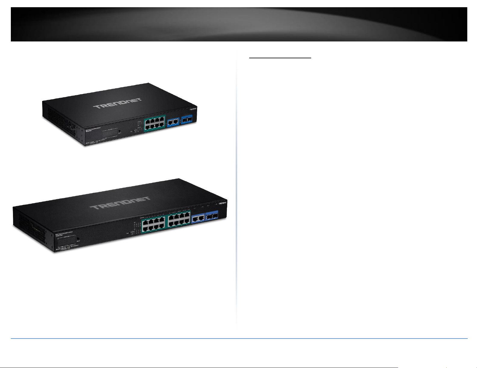
TPE-3012LS
TPE-3018LS
Package Contents
In addition to your switch, the package includes:
• Quick Installation Guide
• Power cord (1.5m/5 ft.)
• Rackmount kit
If any package contents are missing or damaged, please contact the retail store, online
retailer, or reseller/distributor from which the product was purchased.
Page 6

© Copyright 2020 TRENDnet. All Rights Reserved.
TRENDnet User’s Guide
TPE-3012LS / TPE-3018LS
2
Features
TRENDnet’s Gigabit PoE+ Smart Surveillance Switch series is designed to simplify the
installation and management of surveillance networks, especially for integrators and
installers. These ONVIF switches are optimized for the surveillance industry; surveillance
mode provides a graphical dashboard interface with detailed information about the
switch and each connected PoE device. Connect ONVIF compliant IP cameras and NVRs
for more advanced capabilities such as changing device IP settings, and to view
individual IP camera video within the switch GUI. The Smart Surveillance Switches are
also PoE self-healing switches featuring PoE device auto-recovery and power scheduling.
Installers and integrators can save on equipment costs and reduce installation time with
TRENDnet’s Gigabit PoE+ Smart Surveillance Switches by delivering up to 30W per port
of PoE power and data over existing Ethernet cables. Available PoE port controls include
enabling and disabling PoE, PD alive check, and power scheduling. PD alive check is an
automated PoE self-healing switch feature that attempts to recover an unresponsive
PoE device connected to the switch. If a PoE device such as a PoE camera becomes
unresponsive to pings, the ONVIF compliant switch will auto-reboot the PoE port in an
attempt to recover the device.
These PoE+ ONVIF switches feature a 4-digit LED display showing total PoE power,
available power, and power-per-port. They also support long distance PoE+ networking
up to 656 ft./200m away at speeds up to 10mbps. TRENDnet’s Gigabit PoE+ Smart
Surveillance Switches also feature SFP slots to support long-distance fiber networking
applications.
Advanced managed switch features include LACP to group ports to increase bandwidth
between switches, VLANs for segmenting and isolating virtual LAN groups, QoS for
traffic prioritization, port bandwidth controls, and SNMP monitoring, making this ONVIF
switch a powerful SMB network solution. Improve voice performance by isolating and
prioritizing VoIP traffic from normal data traffic with the easy-to-use voice VLAN feature.
Hardware Design
Provides gigabit PoE+ ports, SFP slots for fiber connectivity, and a 1U 19” rackmount
design with brackets included
PoE Power
Each PoE+ managed ONVIF switch supplies up to 30W of power per port and data over a
single Ethernet cable to PoE devices
Surveillance Mode
ONVIF switches are optimized for the surveillance industry, proving a graphical
dashboard interface with useful information about the switch and each connected
device
Troubleshooting
Real-time traffic comparison charts, error group charts, and a convenient cable
diagnostic test aid in rapid troubleshooting.
Long Range PoE+
Long distance PoE+ networking up to 656 ft./200m away at speeds up to 10mbps
4-Digit PoE LED Display
4-digit 7-segment LED display to view total power, available power, and power-per-port
IPv6 Ready
ONVIF switches support IPv6 configuration and IPv6 neighbor discovery
Traffic Management
Managed switch features include: Link aggregation, 802.1Q VLAN, Voice VLAN,
Surveillance VLAN, RSTP, MSTP, Loopback Detection, QoS, and port bandwidth
management
Troubleshooting
A convenient cable diagnostic test and traffic statistics aid in network troubleshooting
Monitoring
RMON, SNMP, and Port Mirroring support administrator monitoring solutions
Page 7
© Copyright 2020 TRENDnet. All Rights Reserved.
TRENDnet User’s Guide
TPE-3012LS / TPE-3018LS
3
Product Hardware Features
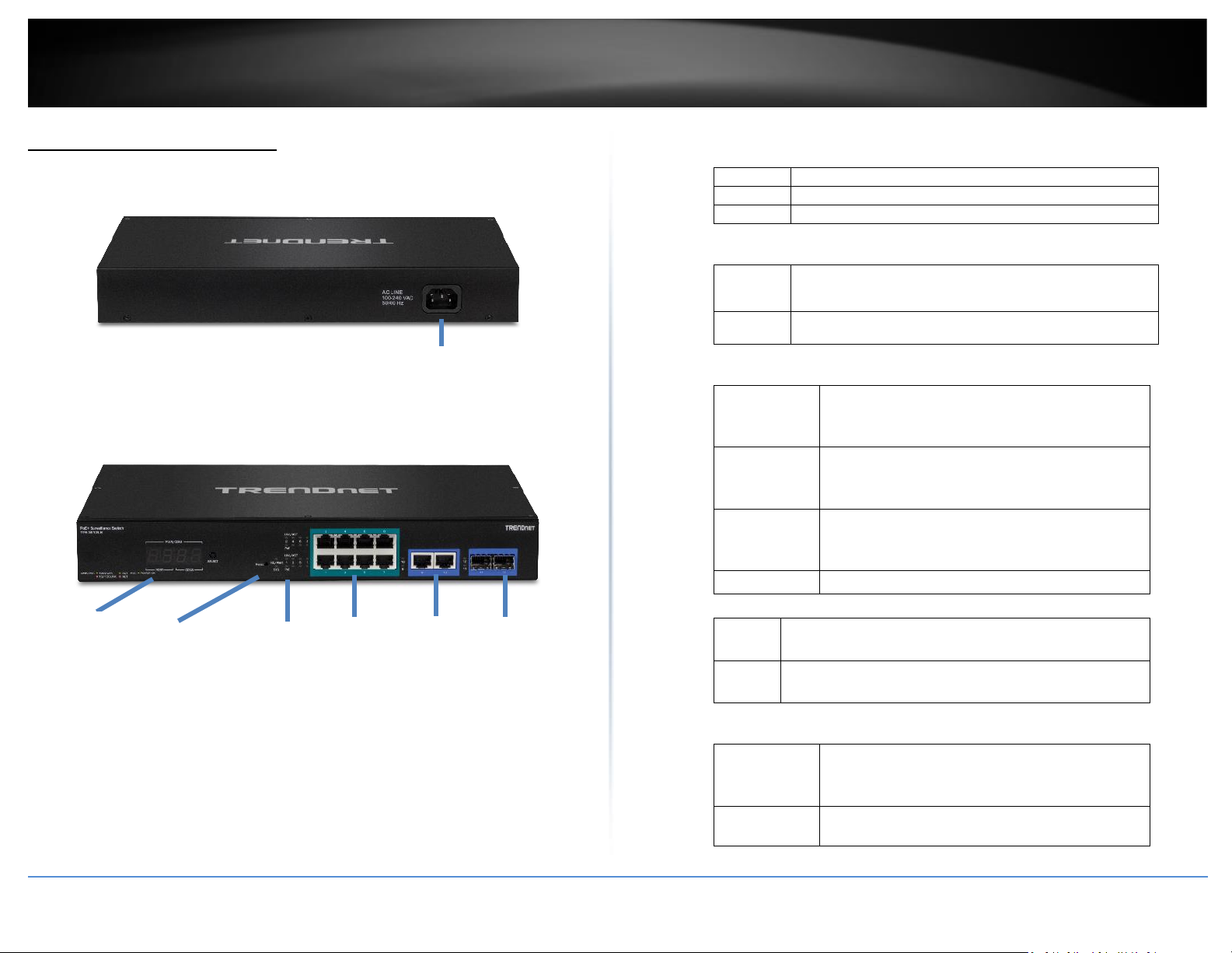
TPE-3012LS
Rear View
• AC Power Connector – Connect the AC power cord to the connector and the
other side into a power outlet. (Input: 100~240VAC, 50/60Hz)
Front View
•
• 4-Digit 7-Segment Display - Displays total power, available power, and
power consumption per port using the toggle button.
• Reset Button – Press and hold this button for 10 seconds and release to
reset the switch to factory defaults.
• PoE+ Gigabit Ports (1-8) – Connect PoE and non-PoE network devices.
• Gigabit Ports (9-10) – Connect non-PoE devices or uplinks.
• SFP Slots (11-12) – Supports optional 1000BASE-SX/LX mini-GBIC
modules.
• Diagnostic LED Indicators
SYS LED
On : The device is receiving power.
Blinking
:
The device is booting up.
Off : The device powered off or not receiving power.
PoE Alert
On : When reaching near the max PoE power budget provided
100W or above, the LED will turn on to indicate that PoE
power consumption is near max. budget available.
Off : When the PoE power provided is below the 100W PoE
power budget.
PoE+ Gigabit Ports (1-8)
On : When the Link/ACT LED lights on, the respective
port is successfully connected to an Ethernet
network.
Green/Amber
Green indicates the link is connected at 1000Mbps.
Amber indicates the link is connected at
10/100Mbps.
Blinking
:
When the Link/ACT LED is blinking, the port is
transmitting or receiving data on the Ethernet
network.
Off : No link.
PoE (Power over Ethernet)
Green
:
When the PoE powered device (PD) is connected and the
port supplies power normally.
Off No PoE powered device (PD) connected or unplugged the
PoE output port.
Gigabit Ports (9-10)
On : When the Link/ACT LED lights on, the respective
port is successfully connected to an Ethernet
network.
Green/Amber
Green indicates the link is connected at 1000Mbps.
Amber indicates the link is connected at
AC Power Connector
Gigabit
Ports
PoE+ Gigabit
Ports
Reset
Button
Diagnostic
LEDs
SFP
Slots
4-Digit
Display
Page 8
© Copyright 2020 TRENDnet. All Rights Reserved.
TRENDnet User’s Guide
TPE-3012LS / TPE-3018LS
4
10/100Mbps.
Blinking
:
When the Link/ACT LED is blinking, the port is
transmitting or receiving data on the Ethernet
network.
Off : No link.
SFP Slots (11-12)
Green on
:
When the mini-GBIC Green LED lights on, the
respective port is inserted mini-GBIC Gigabit
module.
Green blinking
:
When the mini-GBIC Green LED is blinking, the port
is transmitting or receiving data on the Gigabit
network.
Amber on
When the mini-GBIC Amber LED lights on, the
respective port is inserted mini-GBIC 100Mbps
module.
Amber blinking
When the mini-GBIC Amber LED is blinking, the
port is transmitting or receiving data on the
Ethernet network.
Off No link
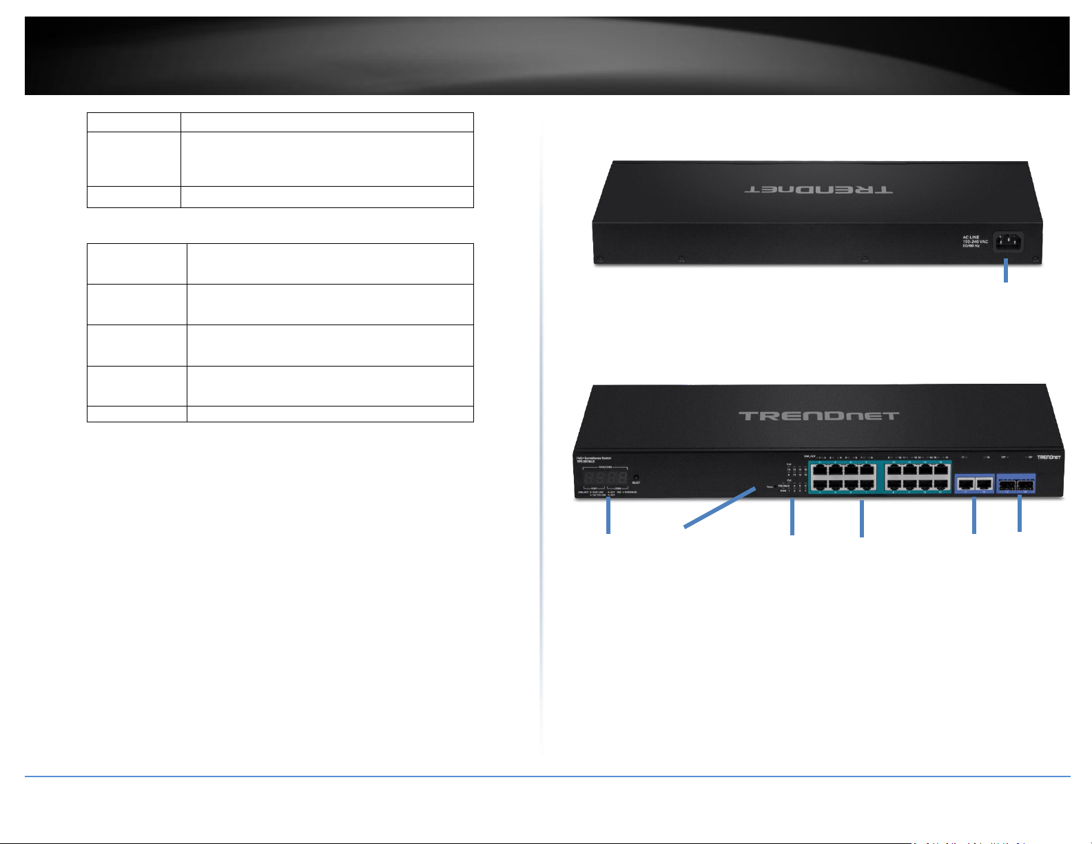
TPE-3018LS
Rear View
• AC Power Connector – Connect the AC power cord to the connector and the
other side into a power outlet. (Input: 100~240VAC, 50/60Hz)
Front View
•
• 4-Digit 7-Segment Display - Displays total power, available power, and
power consumption per port using the toggle button.
• Reset Button – Press and hold this button for 10 seconds and release to
reset the switch to factory defaults.
• PoE+ Gigabit Ports (1-16) – Connect PoE and non-PoE network devices.
• Gigabit Ports (17-18) – Connect non-PoE devices or uplinks. Disabled if
SFP slots 17F or 18F are used.
• SFP Slots Shared (17F-18F) – Supports optional 1000BASE-SX/LX mini-
GBIC modules.
AC Power Connector
Gigabit
Ports
PoE+ Gigabit
Ports
Reset
Button
Diagnostic
LEDs
SFP
Slots
4-Digit
Display
Page 9
© Copyright 2020 TRENDnet. All Rights Reserved.
TRENDnet User’s Guide
TPE-3012LS / TPE-3018LS
5
• Diagnostic LED Indicators
SYS LED
On : The device is receiving power.
Blinking
:
The device is booting up.
Off : The device powered off or not receiving power.
PoE Alert
On : When reaching near the max PoE power budget provided
200W or above, the LED will turn on to indicate that PoE
power consumption is near max. budget available.
Off : When the PoE power provided is below the 200W PoE
power budget.
PoE+ Gigabit Ports (1-16)
On : When the Link/ACT LED lights on, the respective
port is successfully connected to an Ethernet
network.
Green/Amber
Green indicates the link is connected at 1000Mbps.
Amber indicates the link is connected at
10/100Mbps.
Blinking
:
When the Link/ACT LED is blinking, the port is
transmitting or receiving data on the Ethernet
network.
Off : No link.
PoE (Power over Ethernet)
Green
:
When the PoE powered device (PD) is connected and the
port supplies power normally.
Off No PoE powered device (PD) connected or unplugged the
PoE output port.
Gigabit Ports (17-18)
On : When the Link/ACT LED lights on, the respective
port is successfully connected to an Ethernet
network.
Green/Amber
Green indicates the link is connected at 1000Mbps.
Amber indicates the link is connected at
10/100Mbps.
Blinking
:
When the Link/ACT LED is blinking, the port is
transmitting or receiving data on the Ethernet
network.
Off : No link.
SFP Slots Shared (17F-18F)
Green on
:
When the mini-GBIC Green LED lights on, the
respective port is inserted mini-GBIC Gigabit
module.
Green blinking
:
When the mini-GBIC Green LED is blinking, the port
is transmitting or receiving data on the Gigabit
network.
Amber on
When the mini-GBIC Amber LED lights on, the
respective port is inserted mini-GBIC 100Mbps
module.
Amber blinking
When the mini-GBIC Amber LED is blinking, the
port is transmitting or receiving data on the
Ethernet network.
Off No link
Page 10
© Copyright 2020 TRENDnet. All Rights Reserved.
TRENDnet User’s Guide
TPE-3012LS / TPE-3018LS
6
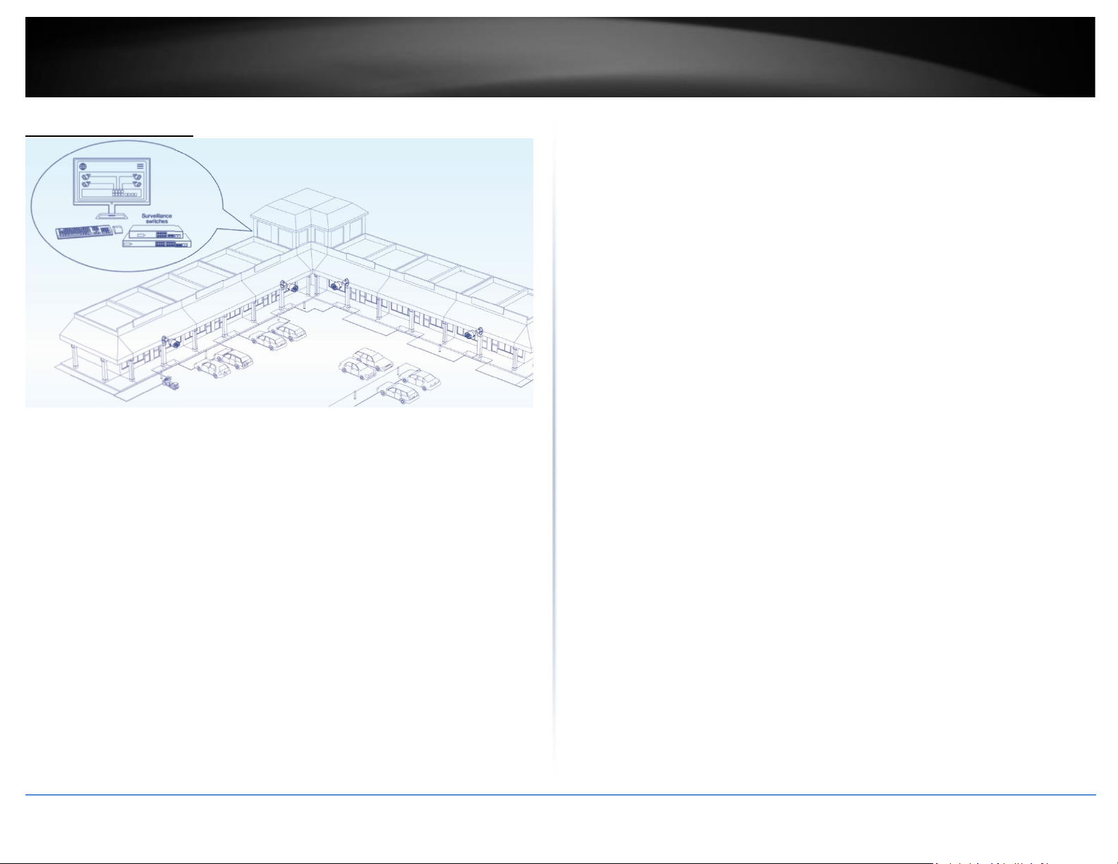
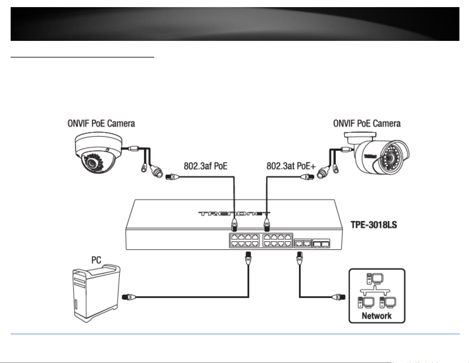
Application Diagram
The Gigabit PoE+ Surveillance Switches are installed and providing PoE/PoE+ and data
connectivity to the PoE surveillance IP cameras. The surveillance switches also offer additional
management features via the ONVIF protocol and other self-healing features such as PD alive
check to automatically recover PoE devices or reboot the switch if the PoE devices are
unresponsive. The switches to your network through the non-PoE Gigabit Ethernet uplink port or
SFP fiber to a switch that is connected to your network.
Page 11
© Copyright 2020 TRENDnet. All Rights Reserved.
TRENDnet User’s Guide
TPE-3012LS / TPE-3018LS
7
Switch Installation
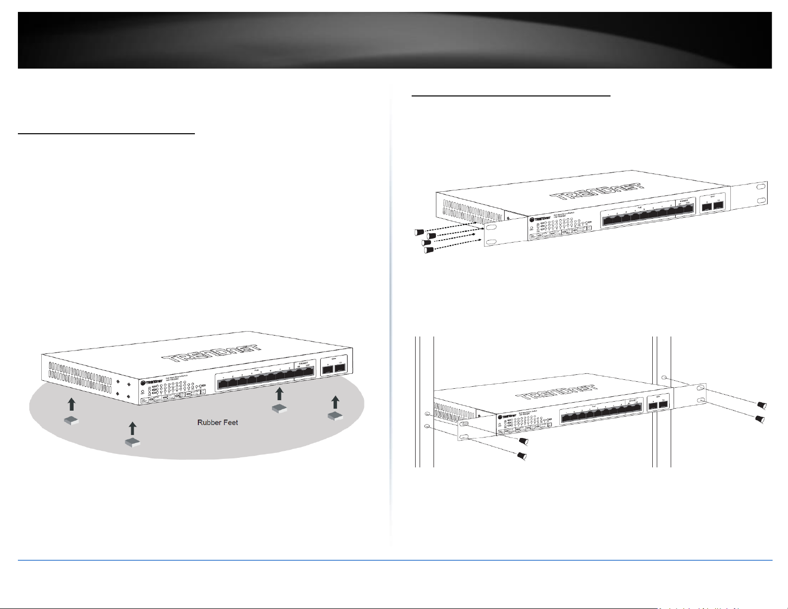
Desktop Hardware Installation
The site where you install the hub stack may greatly affect its performance. When
installing, consider the following pointers:
• Install the Switch in a fairly cool and dry place.
• Install the Switch in a site free from strong electromagnetic field generators (such
as motors), vibration, dust, and direct exposure to sunlight.
• Leave at least 10cm of space at the front and rear of the hub for ventilation.
• Install the Switch on a sturdy, level surface that can support its weight, or in an
EIA standard-size equipment rack. For information on rack installation, see the
next section, Rack Mounting.
• When installing the Switch on a level surface, attach the rubber feet to the
bottom of each device. The rubber feet cushion the hub and protect the hub
case from scratching.
Rack Mount Hardware Installation
The switch can be mounted in an EIA standard-size, 19-inch rack, which can be placed in
a wiring closet with other equipment. Attach the mounting brackets at the switch’s
front panel (one on each side), and secure them with the provided screws.
Then, use screws provided with the equipment rack to mount each switch in the rack.
Page 12
© Copyright 2020 TRENDnet. All Rights Reserved.
TRENDnet User’s Guide
TPE-3012LS / TPE-3018LS
8
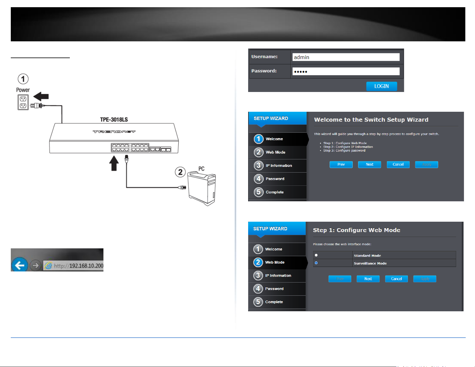
Basic Installation
. Assign a static IP address to your computer’s network adapter in the subnet of
192.168.10.x (e.g. 192.168.10.25) and a subnet mask of 255.255.255.0.
4. Open your web browser, and type the IP address of the switch in the address bar, and
then press Enter. The default IP address is 192.168.10.200.
5. Enter the User Name and Password, and then click Login. By default:
User Name: admin
Password: admin
Note: User name and password are case sensitive.
6. On the Setup Wizard page, click Next.
7. For the web interface mode, select Surveillance Mode and click Next.
Page 13
© Copyright 2020 TRENDnet. All Rights Reserved.
TRENDnet User’s Guide
TPE-3012LS / TPE-3018LS
9
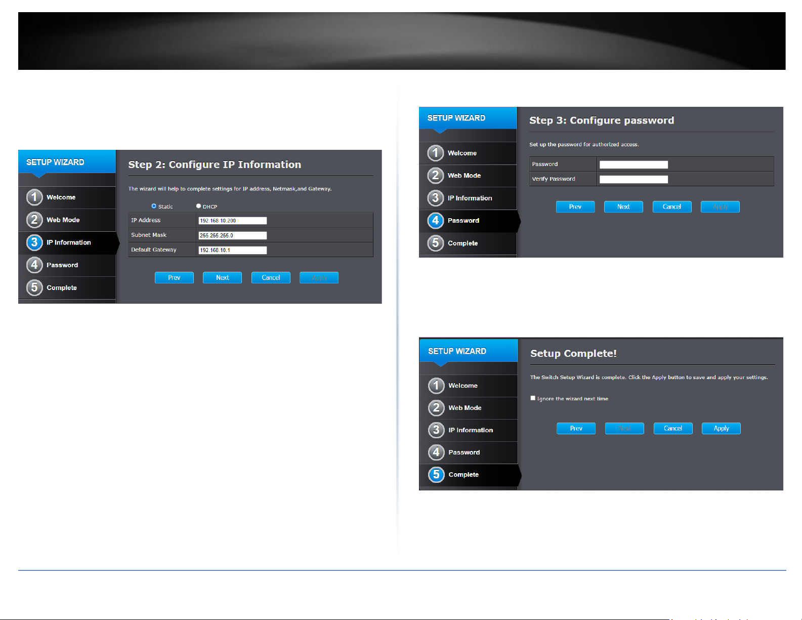
8. For the IP address information, configure the switch to match the requirements of
your network by entering the appropriate IP Address, Subnet Mask, and Default
Gateway settings, then click Next.
Note: You may need to modify the static IP address settings of your computer’s network
adapter to IP address settings within your subnet to regain access to the switch.
9. Create a new administrator password for management access to the switch by
entering a new password in the fields provided, then click Next.
10. On the final setup wizard page, you can check the “Ignore the wizard next time”
option to prevent the setup wizard prompt from appearing at the next login to the web
management interface, then click Apply.
Page 14
© Copyright 2020 TRENDnet. All Rights Reserved.
10
TRENDnet User’s Guide
TPE-3012LS / TPE-3018LS
Connect additional devices to your switch
You can connect additional computers or other network devices PoE (Power over Ethernet) or non-PoE devices to your switch using Ethernet cables to connect them to one of the
available PoE+ Gigabit Ports (TPE-3012LS PoE+ ports 1-8 / TPE-3018LS PoE+ ports 1-16) or Gigabit ports (TPE-3012LS Gigabit ports 9-10 / TPE-3018LS Gigabit ports 17-18). Check the
status of the LED indicators on the front panel of your switch to ensure the physical cable connection from your computer or device.
Note: If you encounter issues connecting to your network, there may be a problem with your computer or device network settings. Please ensure that your computer or device network
settings (also called TCP/IP settings) are configured properly within the network subnet your switch is connected. The switch model may be different than the one shown in the example
below.
Page 15
© Copyright 2020 TRENDnet. All Rights Reserved.
TRENDnet User’s Guide
TPE-3012LS / TPE-3018LS
11
Access your switch management page
Note: Your switch default management IP address http://192.168.10.200 is accessed
through the use of your Internet web browser (e.g. Internet Explorer®, Firefox®,
Chrome™, Safari®, Opera™) and will be referenced frequently in this User’s Guide.
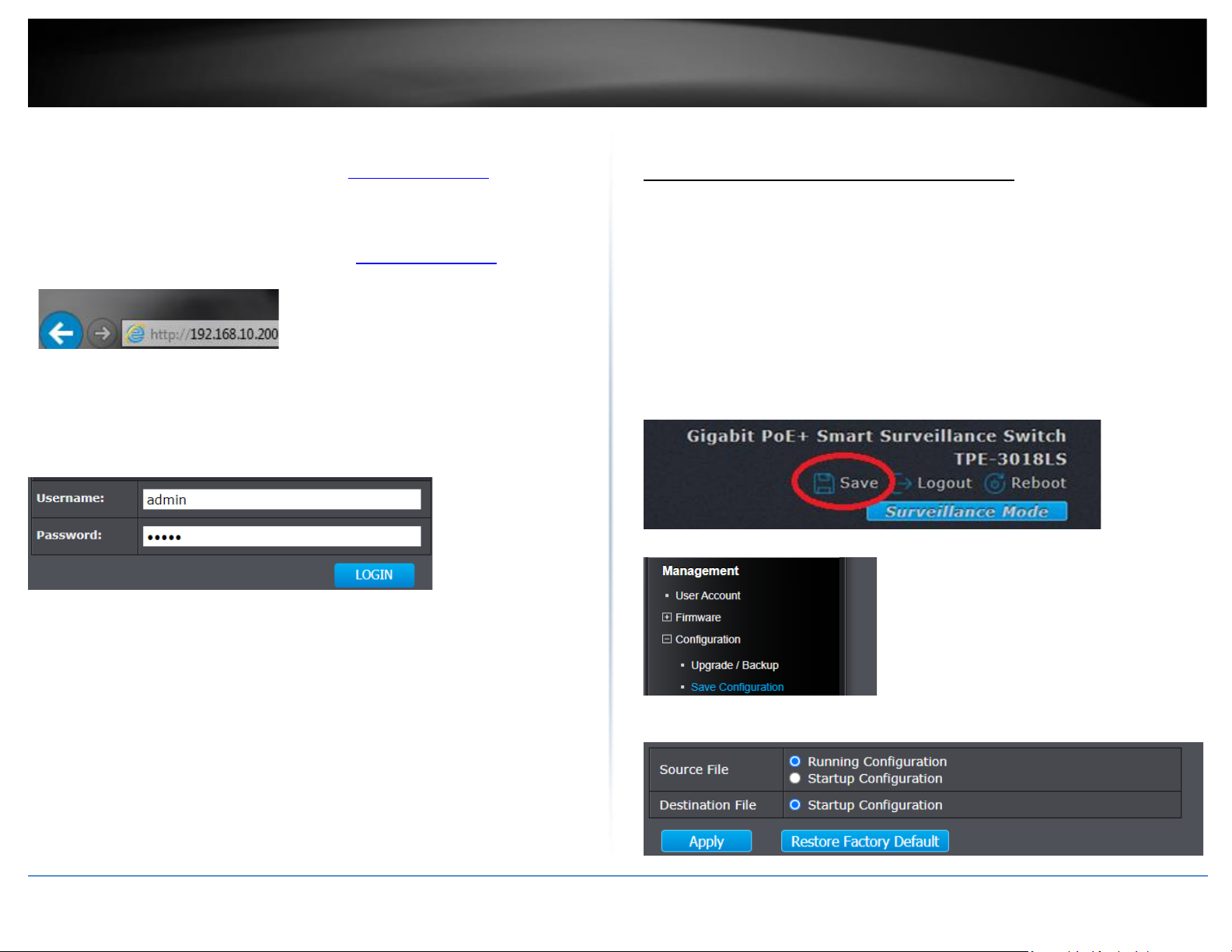
1. Open your web browser and go to the IP address http://192.168.10.200. Your switch
will prompt you for a user name and password.
2. Enter the user name and password. By default:
User Name: admin
Password: admin
Note: User Name and Password are case sensitive.
Saving configuration and switch between web modes
Saving configuration changes to NV-RAM
After applying configuration changes in the switch management, the configuration
changes must be saved to startup configuration or NV-RAM (non-volatile random access
memory) to keep configuration changes after the device reboots. If changes are not
saved to NV-RAM, they will be lost after device reboots. After applying configuration
changes, please make sure to commit changes to NV-RAM one of the sections below.
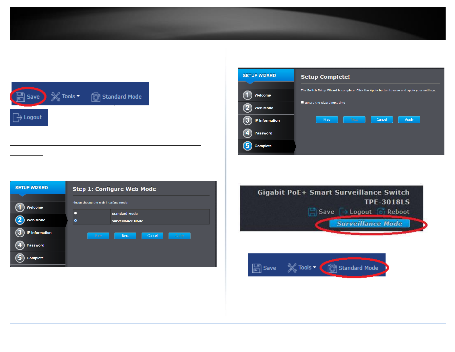
Standard Mode GUI
Click Save at the top right to commit changes to NV-RAM.
Note: You can also click Logout to log out of the switch management page, Reboot to
initiate a switch reboot, Surveillance Mode to switch to the Surveillance Mode GUI
switch management.
You can also click Management, click on Configuration, and click on Save Configuration.
In the main window, click Apply with the Running config as the source and Startup
config as the destination to save changes to NV-RAM.
Page 16
© Copyright 2020 TRENDnet. All Rights Reserved.
TRENDnet User’s Guide
TPE-3012LS / TPE-3018LS
12
Surveillance Mode GUI
Click Save at the top left to commit changes to NV-RAM.
Note: You can also click Standard Mode to switch to the Standard Mode GUI switch
management. Click Logout to logout at the top right of the switch management page.
Switching between Standard and Surveillance Mode web interfaces
In the initial Setup Wizard, you can configure which GUI mode will load by default after
logging into the switch management page. By default, the Standard mode GUI is
configured.
By selecting the “Ignore the wizard next time” at the last step of the setup wizard, the
setup wizard will no longer appear after log and the web interface mode set will
automatically load after logging in.
You can manually switch between web interface modes using the buttons noted below.
Standard Mode GUI
Surveillance Mode GUI
Page 17
© Copyright 2020 TRENDnet. All Rights Reserved.
TRENDnet User’s Guide
TPE-3012LS / TPE-3018LS
13
Surveillance Mode Web Interface
The surveillance mode interface provides a simplified graphical interface including only
the most commonly used features. To access all the switch features, please use the
standard mode web interface.
Dashboard
The Surveillance Mode Web Interface dashboard will provide an overview of which
ports are used, total PoE budget, total PoE power consumed, and the devices
connected. Additionally, you can easily turn PoE on or off in the Overview page.
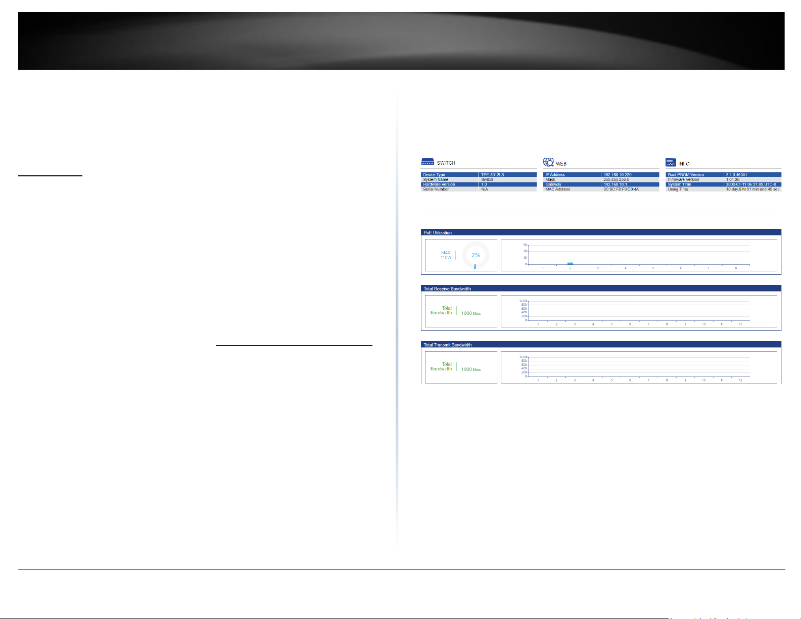
Status
Status
The status page will display switch system information such as model number, hardware
version, IP address settings, MAC and firmware version. Additionally, this page will
provide the total PoE budget power utilization/consumption and total currently
aggregated receive and transmit bandwidth per port.
1. Log into your switch management page (see “Access your switch management page”
on page 11).
2. Click on Switch Model Number in the top left and click the Status tab.
3. Review the information below.
Switch
• Device Type – Displays the model name of the switch.
• System Name – Displays the currently assigned system name.
• Hardware Version – Displays the switch hardware version
• Serial Number – Display the switch serial number.
Web
• IP Address – Displays the currently assigned IPv4 address.
• Mask – Displays the currently assigned IPv4 subnet mask.
• Gateway – Displays the currently assigned IPv4 default gateway.
• MAC Address – Displays the switch MAC address.
Info
• Boot PROM Version – Displays the switch current boot loader version.
• Firmware Version – Displays the switch current firmware version.
• System Time – Displays the switch device date and time.
• Using Time – Displays the switch uptime running continuous operation without
reboot or interruptions.
Note: Port numbers will be indicated at the bottom of the display charts. Hovering over
your mouse cursor over the chart will provide more detail.
Page 18
© Copyright 2020 TRENDnet. All Rights Reserved.
TRENDnet User’s Guide
TPE-3012LS / TPE-3018LS
14
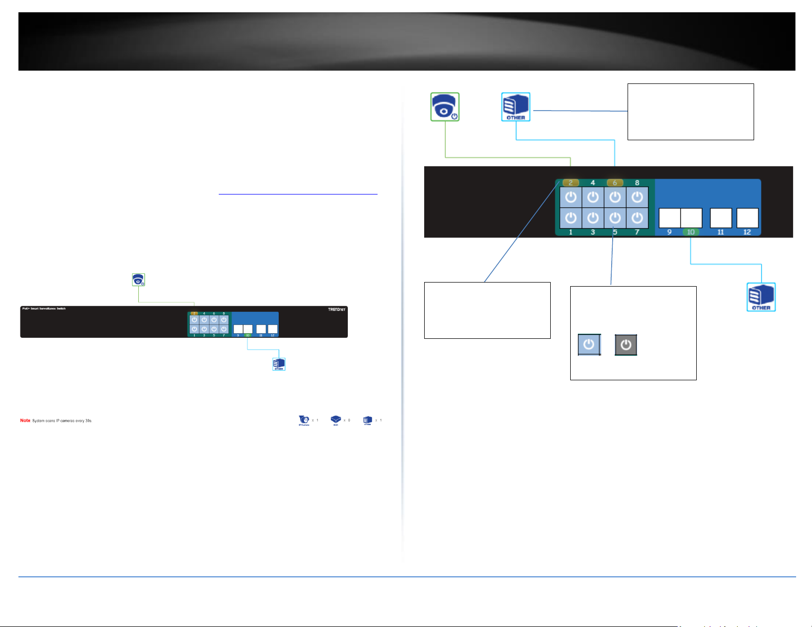
Overview
Overview
The overview page will provide a display of the front panel and icons representing
connected devices or links. Additinally, this page will display specifically if IP cameras are
connected or other links and also display the data link speed the devices are connected.
PoE can also be enabled or displayed on each port.
1. Log into your switch management page (see “Access your switch management page”
on page 11).
2. Click on TPE-3012LS or TPE-3018LS (depending on the switch model) in the top left
and click the Overview tab.
Note: The switch will scan for connected device every 30 seconds. Additionally, the green
colored ports on the front indicate which ports are PoE and blue which ports are data
ports only.
Port Number
Amber: 10/100Mbps
Green: Gigabit
PoE On/Off Button: Click
the port PoE button to
turn PoE on or off.
On Off
Icons will indicate
whether the device is an
IP camera or other.
Page 19
© Copyright 2020 TRENDnet. All Rights Reserved.
TRENDnet User’s Guide
TPE-3012LS / TPE-3018LS
15
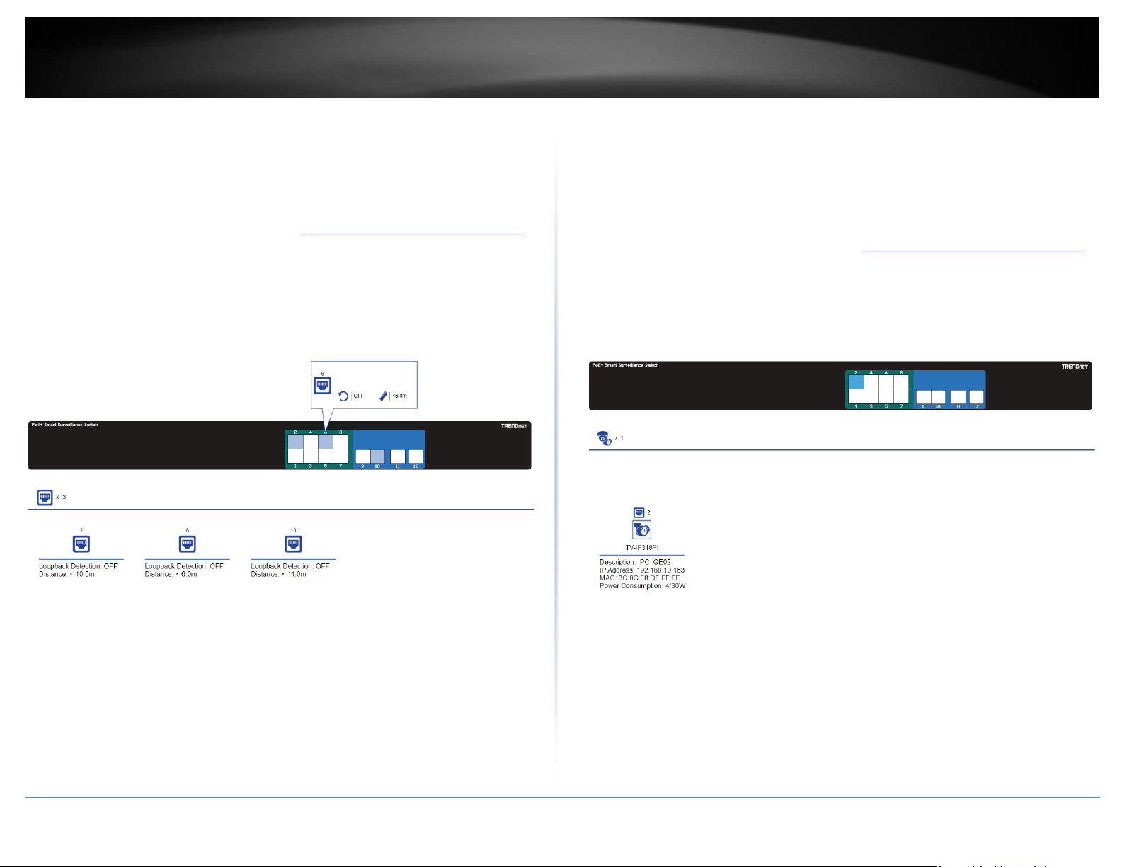
Port Info
Port Info
The port info. page which indicate which ports are connected, the approximated
distance between the switch and the connected device, the loopback detection status.
1. Log into your switch management page (see “Access your switch management page”
on page 11).
2. Click on TPE-3012LS or TPE-3018LS (depending on the switch model) in the top left
and click the Port Info tab.
IP Camera Info
IP Camera Info
The IP Camera Info page will display which ports are specifically connected to IP
cameras and additional info. about the IP cameras such as the detected model number,
IP address, MAC address, and PoE power consumption for each connected IP camera.
1. Log into your switch management page (see “Access your switch management page”
on page 11).
2. Click on TPE-3012LS or TPE-3018LS (depending on the switch model) in the top left
and click the IP Camera Info tab.
Page 20
© Copyright 2020 TRENDnet. All Rights Reserved.
TRENDnet User’s Guide
TPE-3012LS / TPE-3018LS
16
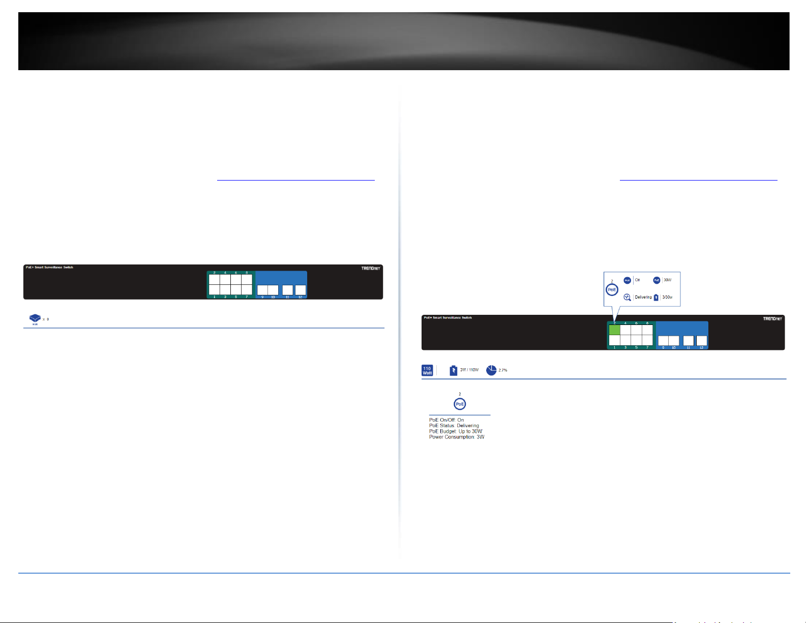
NVR Info
NVR Info
The NVR Info page will display which ports are specifically connected to NVRs and
additional info. about the NVRs such as the detected model number, IP address, MAC
address, and PoE power consumption for each connected NVR.
1. Log into your switch management page (see “Access your switch management page”
on page 11).
2. Click on TPE-3012LS or TPE-3018LS (depending on the switch model) in the top left
and click the NVR Info tab.
PoE Info
PoE Info
The PoE Info page will display which ports are delivery PoE power to the connected
devices, total PoE power budget, total PoE power consumed, and power consumption
for each connected device.
1. Log into your switch management page (see “Access your switch management page”
on page 11).
2. Click on TPE-3012LS or TPE-3018LS (depending on the switch model) in the top left
and click the PoE Info tab.
Page 21
© Copyright 2020 TRENDnet. All Rights Reserved.
TRENDnet User’s Guide
TPE-3012LS / TPE-3018LS
17
PoE Scheduling
PoE Scheduling
This page will allow you to configure schedules when PoE should be enabled or disabled
for each port. Please make sure to configure the time and date settings under Time
before configuring PoE scheduling.
1. Log into your switch management page (see “Access your switch management page”
on page 11).
2. Click on PoE Scheduling.
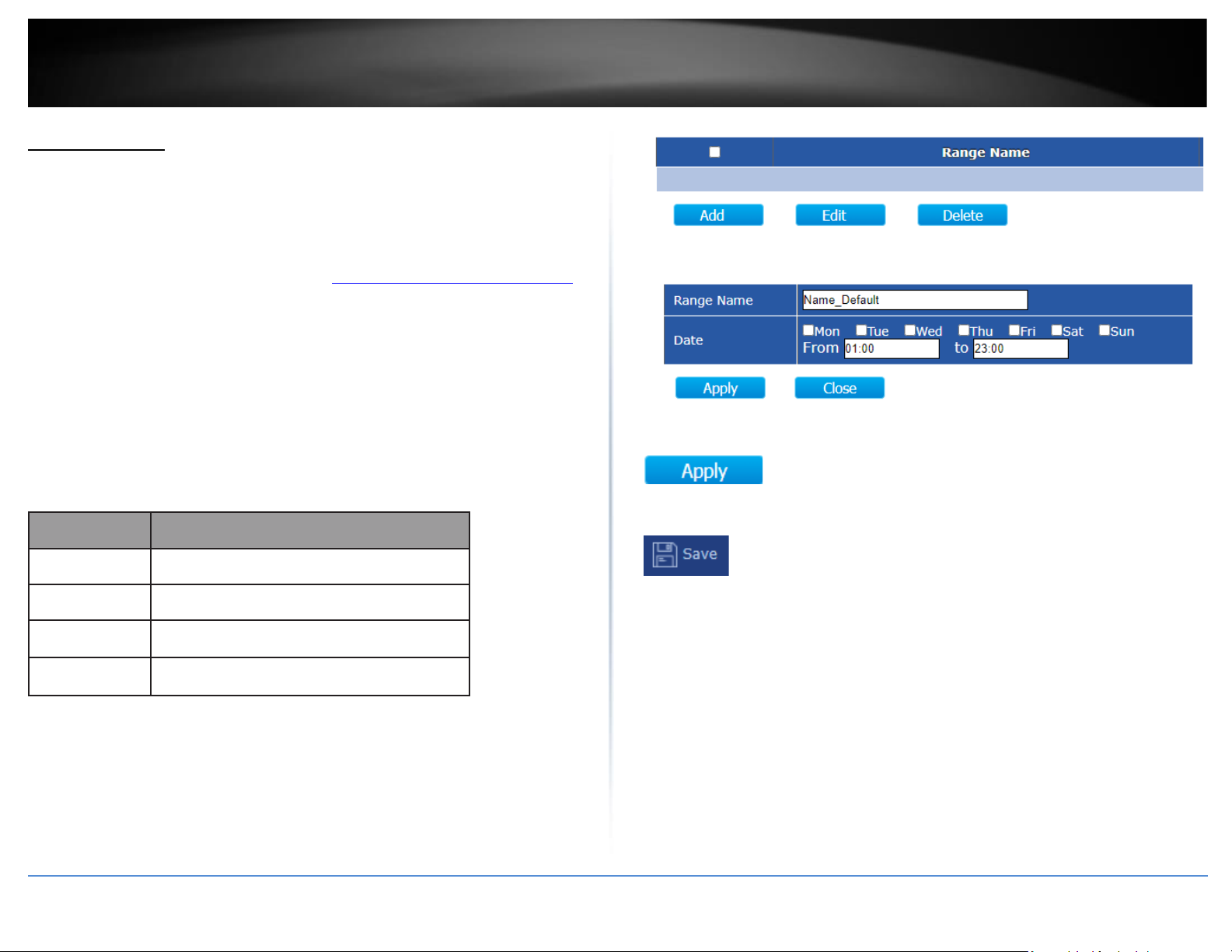
3. Create schedules under the Time Range tab and apply the PoE scheduling
configuration under the Scheduling tab. Review the settings below.
Time Range
Click Add to create a new schedule.
4. After completing your configuration changes, click Apply.
5. Click Save in the top left menu to save configuration to NV-RAM.
Item
Description
Range Name
Select Range name.
Days
Select a valid time for this schedule.
Start Time
Input the Start Time.
End Time
Input the End Time.
Page 22
© Copyright 2020 TRENDnet. All Rights Reserved.
TRENDnet User’s Guide
TPE-3012LS / TPE-3018LS
18
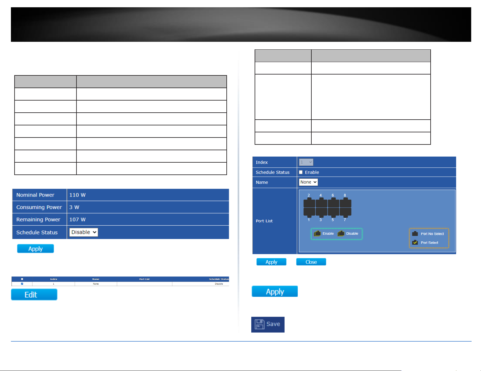
Scheduling
Under the Schedule Status setting, click the drop-down list and Enable to enable PoE
Scheduling.
Item
Description
Nominal Power
Maximum supply power.
Consuming Power
Current consumed power.
Remaining Power
Remaining available power.
Schedule Status
Schedule status global switch.
Name
PoE Schedule Name.
Port List
The ports provide power in designated schedule index.
Schedule Status
The current schedule status.
Select an entry to to configure PoE port scheduling and click Edit.
Item
Description
Index
The serial number of schedule list.
Schedule Status
Schedule Status
•
Checked: Schedule status is enabled.
•
Unchecked: Schedule status is disabled.
Name
Enter the PoE schedule name.
Port List
Select the port provide power.
4. After completing your configuration changes, click Apply.
5. Click Save in the top left menu to save configuration to NV-RAM.
Page 23
© Copyright 2020 TRENDnet. All Rights Reserved.
TRENDnet User’s Guide
TPE-3012LS / TPE-3018LS
19
Time
Time
This section will allow users to configure time and date settings.
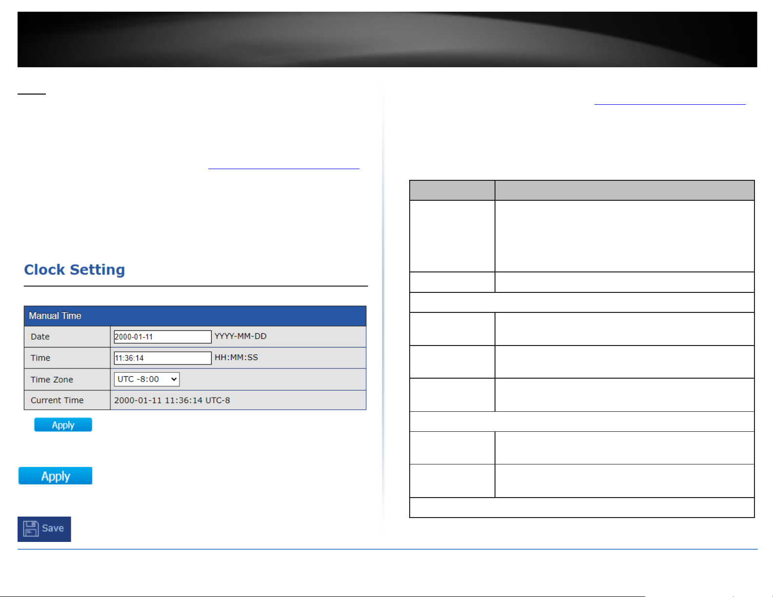
Clock Settings
1. Log into your switch management page (see “Access your switch management page”
on page 11).
2. Click on Time and click on Clock Settings.
3. The date and time and can be manually entered and configured in the options
provided.
4. After completing your configuration changes, click Apply.
5. Click Save in the top left menu to save configuration to NV-RAM.
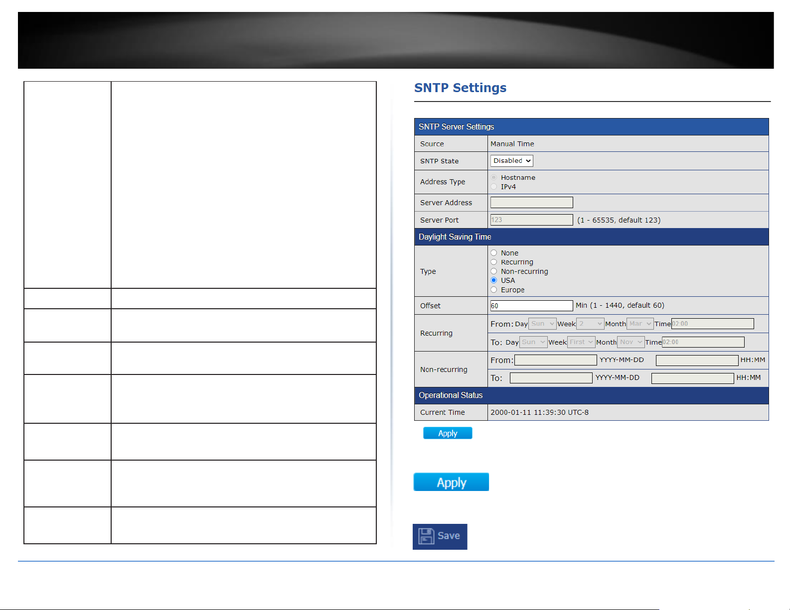
SNTP Settings
1. Log into your switch management page (see “Access your switch management page”
on page 11).
2. Click on Time and click on SNTP SEttings.
3. Review the settings below.
Item
Description
Source
Select the time source.
•
SNTP: Time sync from NTP server.
•
From Computer: Time set from browser host.
Time Zone
Select a time zone difference from listing district.
SNTP
Address Type
Select the address type of NTP server. This is enabled when
time source is SNTP.
Server
Address
Input IPv4 address or hostname for NTP server. This is
enabled when time source is SNTP.
Server Port
Input NTP port for NTP server. Default is 123. This is
enabled when time source is SNTP.
Manual Time
Date
Input manual date. This is enabled when time source is
manual.
Time
Input manual time. This is enabled when time source is
manual.
Daylight Saving Time
Page 24
© Copyright 2020 TRENDnet. All Rights Reserved.
TRENDnet User’s Guide
TPE-3012LS / TPE-3018LS
20
Type
Select the mode of daylight saving time.
•
Disable: Disable daylight saving time.
•
Recurring: Using recurring mode of daylight saving time.
•
Non-Recurring: Using non-recurring mode of daylight
saving time.
•
USA: Using daylight saving time in the United States that
starts on the second Sunday of March and ends on the
first Sunday of November.
•
European: Using daylight saving time in the Europe that
starts on the last Sunday in March and ending on the
last Sunday in October.
Offset
Specify the adjust offset of daylight saving time.
Recurring
From
Specify the starting time of recurring daylight saving time.
This field available when selecting “Recurring” mode.
Recurring To
Specify the ending time of recurring daylight saving time.
This field available when selecting “Recurring” mode.
Non-recurring
From
Specify the starting time of non-recurring daylight saving
time. This field available when selecting “Non-Recurring”
mode.
Non-recurring
To
Specify the ending time of recurring daylight saving time.
This field available when selecting “Non-Recurring” mode.
Non-recurring
From
Specify the starting time of non-recurring daylight saving
time. This field available when selecting “Non-Recurring”
mode.
Non recurring
To
Specify the ending time of recurring daylight saving time.
This field available when selecting “Non-Recurring” mode.
4. After completing your configuration changes, click Apply.
5. Click Save in the top left menu to save configuration to NV-RAM.
Page 25
© Copyright 2020 TRENDnet. All Rights Reserved.
TRENDnet User’s Guide
TPE-3012LS / TPE-3018LS
21
Surveillance Settings
Surveillance Settings
This section will allow users to configure switch settings such as switch IPv4 address
settings, DNS server settings, SNMPT host settings, syslog server, and admin password.
1. Log into your switch management page (see “Access your switch management page”
on page 11).
2. Click on Surveillance Settings.
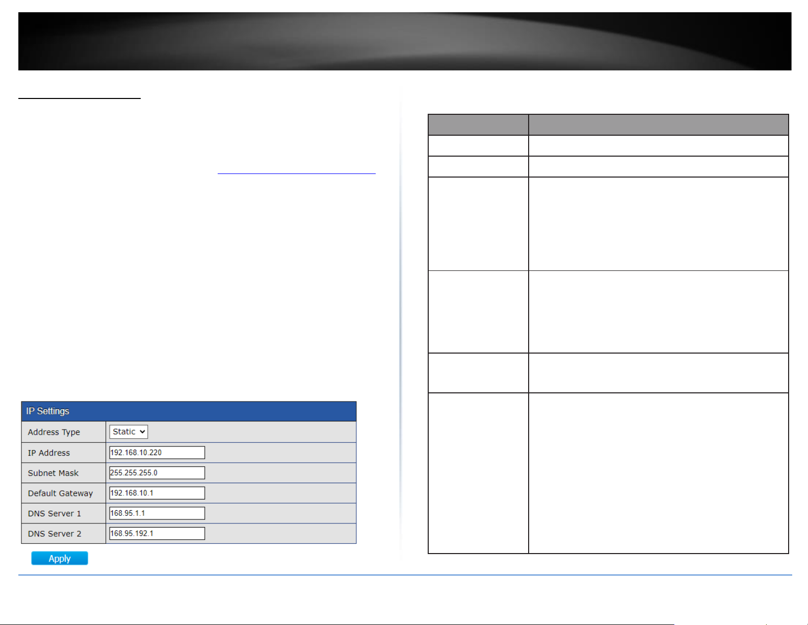
IP Settings After you have completed configuration, click Apply and click Save.
Note: After changing IP address settings, you may need to log into the switch with the
new IP address settings. Please also make sure to click Save.
• Address Type: Select Static to manually specify your IP address settings or
Dynamic to allow your switch to obtain IP address settings automatically from a
DHCP server on your network.
• IP Address: Enter the new switch IP address. (e.g. 192.168.200.200)
• Subnet Mask: Enter the new switch subnet mask. (e.g. 255.255.255.0)
• Default Gateway: Enter the default gateway IP address. (e.g. 192.168.200.1 or
typically your router/gateway to the Internet).
• DNS Server 1: Enter the primary IPv4 DNS server address.
• DNS Server 2: Enter the secondary IPv4 DNS server address.
SNMP Host Settings After you have completed configuration, click Add, Apply, and click Save.
Item
Description
Address Type
Notify recipients host address type.
Server Address
IP address or the hostname of the SNMP trap recipients.
Version
Specify SNMP notification version
•
SNMPv1: SNMP Version 1 notification.
•
SNMPv2: SNMP Version 2 notification.
•
SNMPv3: SNMP Version 3 notification.
Type
Notification Type
•
Trap: Send SNMP traps to the host.
•
Inform: Send SNMP informs to the host.(version 1 have
no inform)
Community/User
SNMP community/user name for notification. If version
is SNMPv3 the name is user name, else is community
Security Level
SNMP notification packet security level, the security
level must less than or equal to the community/user
name
•
No Security: Specify that no packet authentication is
performed.
•
Authentication: Specify that no packet authentication
without encryption is performed.
•
Authentication and Privacy: Specify that no packet
authentication with encryption is performed.
Page 26

© Copyright 2020 TRENDnet. All Rights Reserved.
TRENDnet User’s Guide
TPE-3012LS / TPE-3018LS
22
Server Port
Recipients server UDP port number, if “use default”
checked the value is 162, else user configure.
Timeout
Specify the SNMP informs timeout, if “use default”
checked the value is 15, else user configure.
Retry
Specify the SNMP informs retry count, if “use default”
checked the value is 3, else user configure.
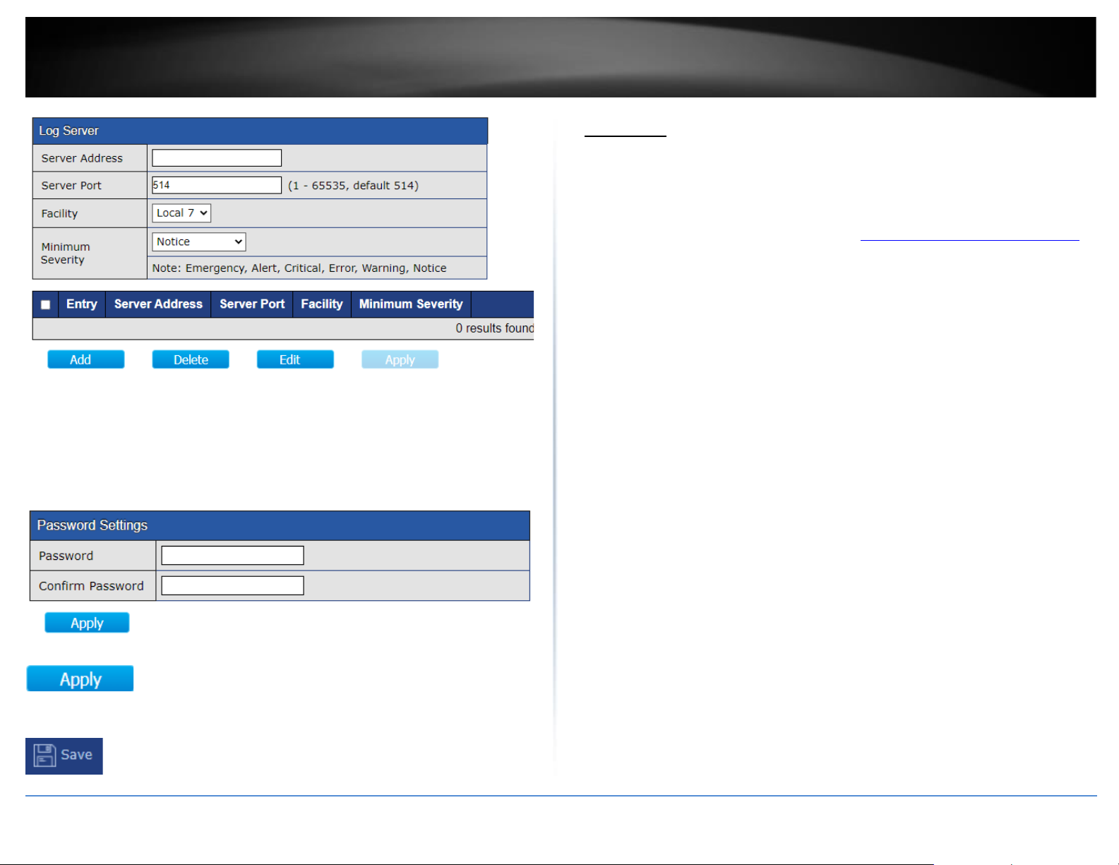
Log Server
This section will allow users to configure an external remote log server or syslog server.
After you have completed configuration, click Add, Apply, and click Save.
Item
Description
Server
The IP address of the remote logging server.
Server
Ports
The port number of the remote logging server.
Facility
The facility of the logging messages. It can be one of the
following values: local0,local1, local2, local3, local4, local5,
local6, and local7.
Severity
The minimum severity.
•
Emergence: System is not usable.
•
Alert: Immediate action is needed.
•
Critical: System is in the critical condition.
•
Error: System is in error condition
has occurred.
•
Informational: Device information.
•
Debug: Provides detailed information about an event.
Page 27
© Copyright 2020 TRENDnet. All Rights Reserved.
TRENDnet User’s Guide
TPE-3012LS / TPE-3018LS
23
Password Settings
This section will allow users to change the admin password to log into the switch
management interface.
After you have completed configuration, click Apply and click Save.
4. After completing your configuration changes, click Apply.
5. Click Save in the top left menu to save configuration to NV-RAM.
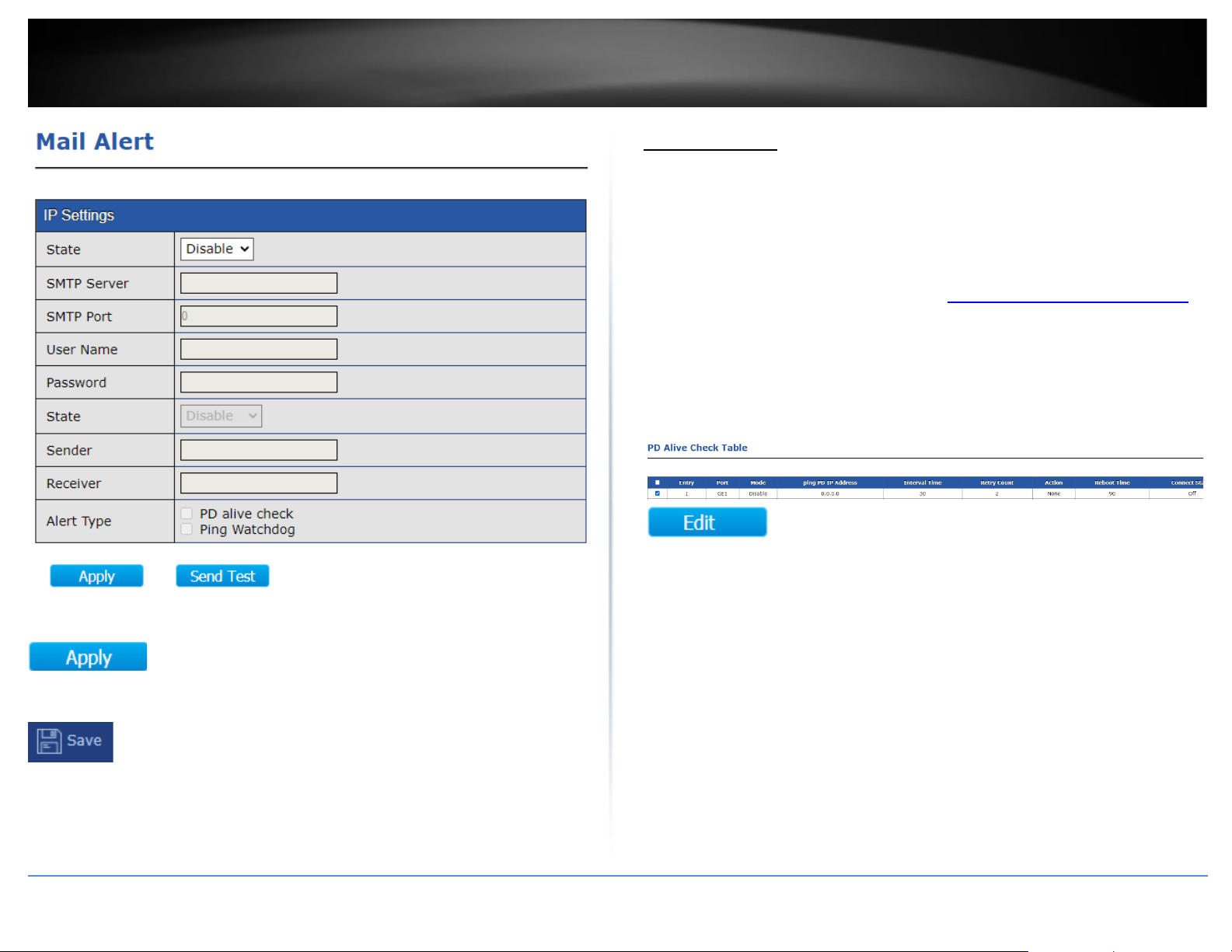
Mail Alert
Mail Alert
This section will allow users to configure email alert notification for PD alive check and
Ping Watchdog.
1. Log into your switch management page (see “Access your switch management page”
on page 11).
2. Click on Mail Alert.
3. Review the settings below.
• State: Select Enable to enable the email notification/alerts.
• SMTP Server: Enter the SMTP server domain name or IP address.
Note: Please make sure the switch IP address default gateway and DNS server
address settings are set correctly for domain name resolution.
• SMTP Port: Enter the SMTP port number used by the SMTP email server.
• User Name: Enter the user name or email account user name.
• Password: Enter the password for the email account.
• State: Select Enable to enable the email notification/alerts.
• Sender: Enter a sender email address.
• Receiver: Enter the receiving email address.
• Alert Type: Select the alert type to send notifications.
o PD Alive: If selecting this option, email notifications will be sent when
PD alive check is activated.
o Ping Watchdog: If selecting this option, email notifications will be sent
ping watchdog is activated.
• Send Test: Use this to verify your SMTP email configuration settings are
configured correctly and email notification is working properly.
Page 28
© Copyright 2020 TRENDnet. All Rights Reserved.
TRENDnet User’s Guide
TPE-3012LS / TPE-3018LS
24
4. After completing your configuration changes, click Apply.
5. Click Save in the top left menu to save configuration to NV-RAM.
PD Alive Check
PD Alive Check
This section will allow users configure PD alive check which as feature that allows the
switch to run a connectivity check on PoE device by pinging the IP address and
automatically turn PoE on and off if connectivity fails to the PoE device in attempt to
restore the PoE device to normal operation.
1. Log into your switch management page (see “Access your switch management page”
on page 11).
2. Click on PD Alive Check.
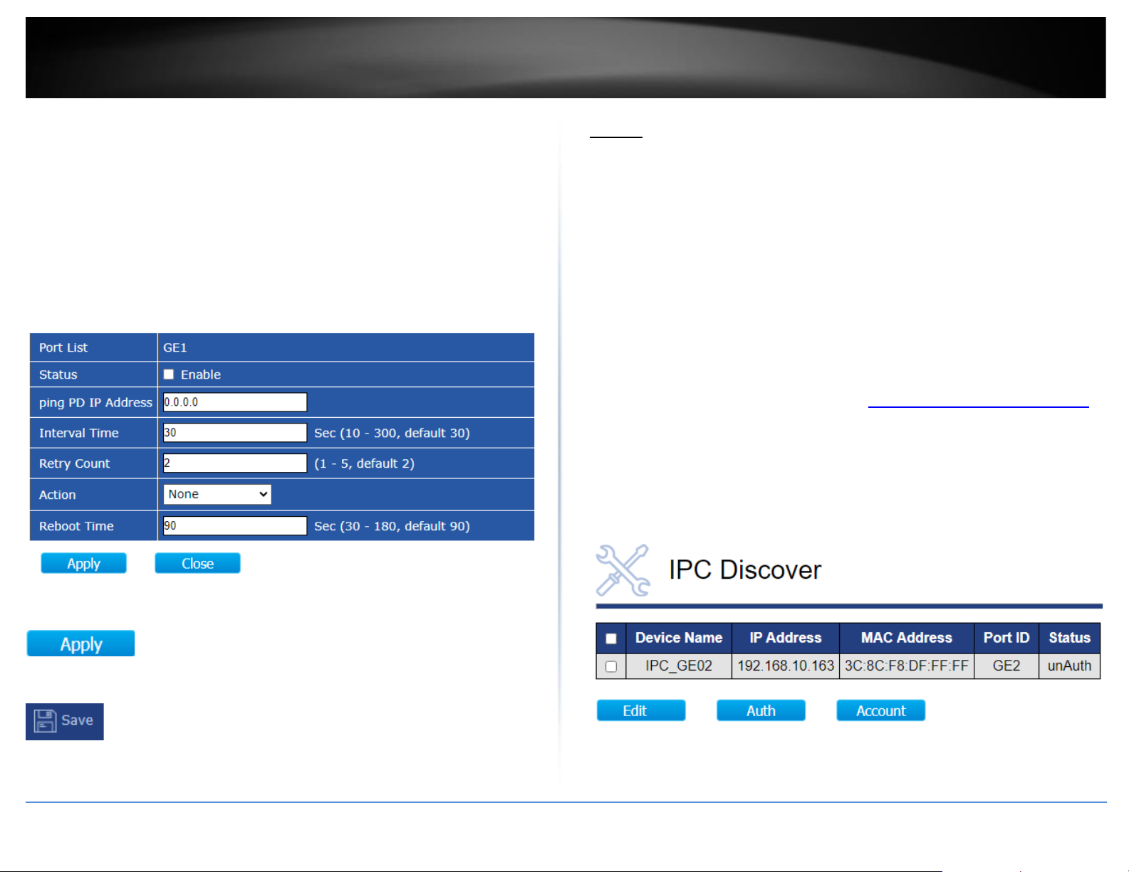
3. Check the PoE port with the PoE device connected to you would like to configure for
PD alive check and click Edit.
4. Check the Enable option for Status to enable PD alive check on the selected port.
Enter the IP Address for the PoE device under the ping PD IP Address (ex:
192.168.10.107)
Review the additional settings below.
• Interval Time – Enter the time in seconds each time the switch will check for a
ping response from the PoE device. (Range: 10 – 300)
• Retry Count – In the case that a ping response fails, enter the number of times
the switch will retry for a ping response before disabling and re-enabling the
PoE port. (Range: 1-5)
• Action – An option must be selected for PD alive check to function.
o None – If the ping response fails according to the time parameters set,
no action will be taken.
Page 29
© Copyright 2020 TRENDnet. All Rights Reserved.
TRENDnet User’s Guide
TPE-3012LS / TPE-3018LS
25
o PD Reboot – If the ping response fails according to the time
parameters set, the switch will disable and re-enable the PoE port
attempting to automatically recover the connected PoE device.
o Reboot&Alarm - If the ping response fails according to the time
parameters set, the switch will disable and re-enable the PoE port
attempting to automatically recover the connected PoE device and
also send out an email notification is configured.
o Alarm - If the ping response fails according to the time parameters set,
the switch will only send out an email notification if configured.
o Reboot Time - If the ping response fails according to the time
parameters set, enter the time in seconds from the time the PoE port
is disabled to the time the PoE port is re-enabled. (Range: 30-180)
4. After completing your configuration changes, click Apply.
5. Click Save in the top left menu to save configuration to NV-RAM.
ONVIF
This section will allow you to configure the ONVIF features available on the switch such
as ONVIF device discovery and authorization. Apply configuration settings to ONVIF
compliant IP cameras such as IP address settings, changing passwords, create users, and
firmware upgrades. The switch is capable of discovering and applying configuration
settings to ONVIF compliant devices connected to the same IP address subnet. The
Surveillance Mode User Interface may provide more graphical-based tools in monitoring
your devices and applying configuration settings.
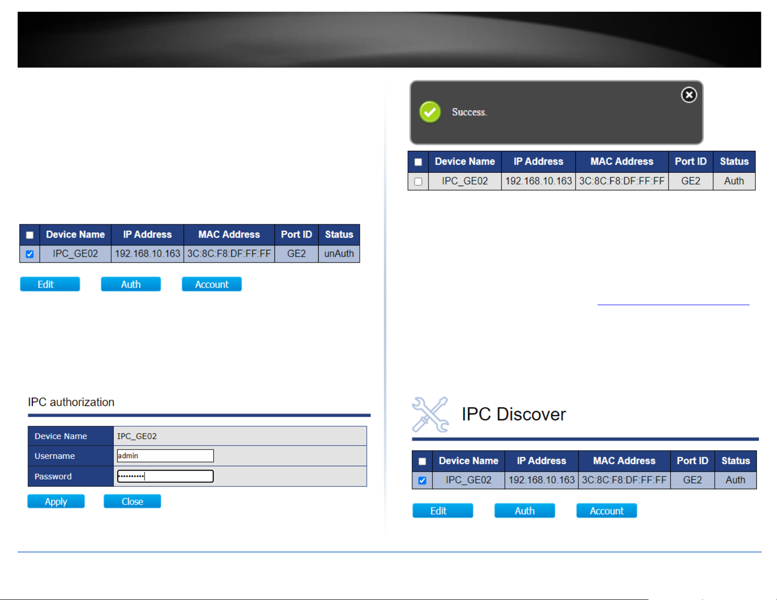
Discovering and authorizing ONVIF compliant devices
ONVIF > IPC Discover
After the surveillance switch has discovered the ONVIF compliant device, the devices
must be authorized with the surveillance switch to apply configuration changes to the
ONVIF devices.
1. Log into your switch management page (see “Access your switch management page”
on page 11).
2. Click on ONVIF and click on IPC Discover. The will list will display a list of the
discovered ONVIF compliant IP cameras found on your network. The list will also
display the IP address, MAC address, and port the device is connected. If the device or
devices are connected to another switch in your network, the list will display the
connected port as the uplink port from your surveillance switch to your network.
Page 30
© Copyright 2020 TRENDnet. All Rights Reserved.
TRENDnet User’s Guide
TPE-3012LS / TPE-3018LS
26
3. Before the surveillance switch can apply any configuration settings to your ONVIF
compliant IP cameras, you must authorize by entering the ONVIF administrator
credentials for each device.
Note: The IP camera administrator user name and password must be configured on
the IP cameras first before they can be used with the surveillance switch. Some IP
cameras may not have configuration options specific to ONVIF but may still comply
with ONVIF. In this case, the IP camera management access user name and password
may be the same as the ONVIF administrator user name and password.
4. To authorize an ONVIF compliant IP camera, check the IP camera in the list and click
Auth.
5. Under the IPC Authorization section, enter the ONVIF administrator user name and
password in the fields provided and click Apply. A success message will appear
indicating that the IP camera has been successfully authorized. Under the Status
column next to the device, the status will change from unAuth to Auth.
Note: If you are unable to successfully authorize the IP camera, please double check
your ONVIF administrator credentials. You can also try to reboot the IP camera.
Applying IP address settings to ONVIF authorized devices
ONVIF > IPC Discover
After ONVIF compliant devices have been discovered and successfully authorized, you
can apply IP address configuration settings to these devices from the surveillance switch
interface.
1. Log into your switch management page (see “Access your switch management page”
on page 11).
2. Click on ONVIF and click on IPC Discover.
3. For the ONVIF devices that have been successfully authorized, check the device in the
list and click Edit.
Page 31

© Copyright 2020 TRENDnet. All Rights Reserved.
TRENDnet User’s Guide
TPE-3012LS / TPE-3018LS
27
4. Under the IPC Device Info Edit section, you can view additional device information,
modify the Device Name and IP address configuration.
5. Scroll down the window to view or modify the device IP address configuration.
6. After you have applied configuration changes, scroll to the bottom of the window and
click Apply. A success message will appear if the configuration changes were
successfully applied.
Note: After the configuration changes have been successfully applied, the device will
appear in the list with the updated information.
Page 32

© Copyright 2020 TRENDnet. All Rights Reserved.
TRENDnet User’s Guide
TPE-3012LS / TPE-3018LS
28
Changing the ONVIF device administrator password
ONVIF > Device Authentication
After ONVIF compliant devices have been discovered and successfully authorized, you
can change the ONVIF administrator password of the ONVIF compliant devices.
1. Log into your switch management page (see “Access your switch management page”
on page 11).
2. Click on ONVIF and click on IPC Discover.
3. For the ONVIF devices that have been successfully authorized, check the device in the
list and click Account.
4. Under the IP Camera List section below, a list of the current user accounts of the
ONVIF device will be listed. To modify the ONVIF administrator password, check the
device in the list with User Level admin and click Edit.
5. Scroll down to the Edit User Account section and you can enter in the administrator
password settings in the password fields provided.
Note: Please note that the ONVIF user password typically requires eight characters for
accounts.
6. After you have applied configuration changes, scroll to the bottom of the window and
click Apply. A success message will appear if the configuration changes were
successfully applied.
Page 33

© Copyright 2020 TRENDnet. All Rights Reserved.
TRENDnet User’s Guide
TPE-3012LS / TPE-3018LS
29
Creating new ONVIF users in the ONVIF device
ONVIF > Device Authentication
After ONVIF compliant devices have been discovered and successfully authorized, you
create new ONVIF users to those devices if supported.
1. Log into your switch management page (see “Access your switch management page”
on page 11).
2. Click on ONVIF and click on Device Authentication.
3. For the ONVIF devices that have been successfully authorized, check the device in the
list and click Account.
4. Under the IP Camera List section below, a list of the current user accounts of the
ONVIF device will be listed. To create a new ONVIF user for the device, check the device
in the list and click Add.
5. Scroll down to the Add User Account section and enter the new account user name
and password in the fields provided. For the User Level, select Operator or User.
Note: Please note that the ONVIF user password typically requires eight characters for
accounts.
6. After you have applied configuration changes, scroll to the bottom of the window and
click Apply. A success message will appear if the configuration changes were
successfully applied.
Page 34

© Copyright 2020 TRENDnet. All Rights Reserved.
TRENDnet User’s Guide
TPE-3012LS / TPE-3018LS
30
Upgrade ONVIF device firmware
ONVIF > Device FW Upgrade
After ONVIF compliant devices have been discovered and successfully authorized, you
can upgrade the firmware of the ONVIF device from the surveillance switch interface.
1. Log into your switch management page (see “Access your switch management page”
on page 11).
2. Click on ONVIF and click on FW Upgrade.
3. Depending on your web browser at the top, for the Filename, click Browse or Choose
File and navigate to the folder on your computer where the unzipped firmware file for
the ONVIF device is located and select it. Then click Apply to upload the firmware file to
the surveillance switch.
4. After the firmware file has been successfully uploaded, a success message will appear
indicating that the firmware file was successfully uploaded. Click Done.
5. The firmware file name will now appear under Filename.
6. In the IP Camera List, check the device you would like to upgrade with the previously
loaded firmware file, then click Upgrade.
Note: If you have multiple devices of the same model that use the same firmware file,
you can upgrade multiple devices of the same model by checking multiple devices in the
list before clicking Upgrade.
The Status will change to uploading indicating that the firmware of the ONVIF device is
upgrading.
If the firmware upgrade was successful, the Status will indicate that upgrade was
successful.
Note: After the ONVIF device has successfully upgraded firmware and reboots, you may
need to re-authorize the ONVIF device again under Discovery > IP Camera.
Page 35

© Copyright 2020 TRENDnet. All Rights Reserved.
TRENDnet User’s Guide
TPE-3012LS / TPE-3018LS
31
E-map Management
ONVIF > E-Map Management
This section will allow users to upload images of floorplans where IP camera can be
placed on as a visual reference to the IP cameras physical locations.
Uploading E-Map Floorplan Images
ONVIF > E-Map Management > Image Upload
1. Log into your switch management page (see “Access your switch management page”
on page 11).
2. Click on ONVIF, click on E-Map Management, and click on Image Upload.
3. Click Add to upload a new floor plan image. Click Browse or Choose File and navigate
to the location of the floorplan image to upload from your local drive, then click Apply
to start the upload.
4. The file name of the image will be displayed after it has been successfully uploaded.
Binding E-Map Images with Location Name
ONVIF > E-Map Management > Image Settings
This section will allow users to set a location to a specific map image.
1. Log into your switch management page (see “Access your switch management page”
on page 11).
2. Click on ONVIF, click on E-Map Management, and click on Image Settings.
3. Select an entry and click Edit.
• Location Name: Enter a location name for the image.
• Map Image: Click the drop-down list to select an uploaded floorplan image to
assign. Click Apply.
Page 36

© Copyright 2020 TRENDnet. All Rights Reserved.
TRENDnet User’s Guide
TPE-3012LS / TPE-3018LS
32
4. The location name and assigned floorplan image filename will appear in the entry.
E-Map View
ONVIF > E-Map Management > E-Map View
This section will allow users to place IP cameras onto the uploaded image floorplans for
visual reference to IP camera installed locations.
1. Log into your switch management page (see “Access your switch management page”
on page 11).
2. Click on ONVIF, click on E-Map Management, and click on E-Map View.
3. Review the settings.
• Location: The drop-down list will contain a list of uploaded image floorplans
that have been uploaded and already binded to a location name.
• Map Scale: Scaling adjustment for reference to the physical of objects in the
uploaded floorplan image.
IP Cameras will be available in the left size of the e-map. Using your mouse, drag and
drop the IP cameras to the locations on the floorplan image for reference to the physical
locations. Click Apply.
Note: Clicking Reset will reset the e-map to default and remove all IP cameras from the
floorplan moved back to the top left of the e-map.
4. After completing your configuration changes, click Apply.
5. Click Save in the top left menu to save configuration to NV-RAM.
Page 37

© Copyright 2020 TRENDnet. All Rights Reserved.
TRENDnet User’s Guide
TPE-3012LS / TPE-3018LS
33
Tools
The tools menu will allow users to view firmware information, upgrade and backup
switch firmware, backup and restore switch configuration, reboot, and reset switch to
factory defaults.
View Firmware Information
Tools > Firmware Information
1. Log into your switch management page (see “Access your switch management page”
on page 11).
2. In the top left menu, click on Tools and click on Firmware Information.
Firmware Upgrade and Backup
Tools > Firmware Upgrade & Backup
1. Log into your switch management page (see “Access your switch management page”
on page 11).
2. In the top left menu, click on Tools and click on Firmware Upgrade & Backup.
• Upgrade from HTTP/TFTP – This section will allow you to upgrade the switch
firmware by HTTP or TFTP protocol methods.
• Backup from HTTP/TFTP - This section will allow you to backup the switch
firmware by HTTP or TFTP protocol methods.
HTTP
Item
Description
Action
Firmware operations
•
Upgrade: Upgrade firmware from remote host to DUT.
•
Backup: Backup firmware image from DUT to remote host.
Page 38

© Copyright 2020 TRENDnet. All Rights Reserved.
TRENDnet User’s Guide
TPE-3012LS / TPE-3018LS
34
Method
Firmware upgrade / backup method.
•
TFTP: Using TFTP to upgrade/backup firmware.
•
HTTP: Using WEB browser to upgrade/backup firmware.
Filename
Use browser to upgrade firmware, you should select firmware
image file on your host PC.
TFTP
Item
Description
Action
Firmware operations
•
Upgrade: Upgrade firmware from remote host to DUT
•
Backup: Backup firmware image from DUT to remote host
Method
Firmware upgrade / backup method
•
TFTP: Using TFTP to upgrade/backup firmware.
•
HTTP: Using WEB browser to upgrade/backup firmware.
Address Type
Specify TFTP server address type
•
Hostname: Use domain name as server address
•
IPv4: Use IPv4 as server address
Server Addres
Specify TFTP server address.
Filename
Firmware image file name on remote TFTP server
Page 39

© Copyright 2020 TRENDnet. All Rights Reserved.
TRENDnet User’s Guide
TPE-3012LS / TPE-3018LS
35
Backup/Restore switch Configuration
Tools > Configuration Backup & Restore
1. Log into your switch management page (see “Access your switch management page”
on page 11).
2. In the top left menu, click on Tools and click on Configuration Backup & Restore.
• Restore from HTTP/TFTP – This section will allow you to restore the switch
configuration by HTTP or TFTP protocol methods.
• Backup from HTTP/TFTP - This section will allow you to backup the switch
configuration by HTTP or TFTP protocol methods.
HTTP
Item
Description
Action
Configuration operations
•
Upgrade: Upgrade firmware from remote host to DUT
•
Backup: Backup firmware image from DUT to remote host
Method
Configuration upgrade / backup method
•
TFTP: Using TFTP to upgrade/backup firmware
•
HTTP: Using WEB browser to upgrade/backup firmware
Configuration
Configuration types
•
Running Configuration: Merge to current running
configuration file
•
Startup Configuration: Replace startup configuration file
Filename
Use browser to upgrade configuration, you should select
configuration file on your host PC.
TFTP
Item
Description
Action
Configuration operations
•
Upgrade: Upgrade firmware from remote host to DUT
•
Backup: Backup firmware image from DUT to remote host
Method
Configuration upgrade / backup method
•
TFTP: Using TFTP to upgrade/backup firmware
Configuration
Configuration types
•
Running Configuration: Merge to current running
configuration file
•
Startup Configuration: Replace startup configuration file
Page 40

© Copyright 2020 TRENDnet. All Rights Reserved.
TRENDnet User’s Guide
TPE-3012LS / TPE-3018LS
36
Address Type
Specify TFTP server address type
•
Hostname: Use domain name as server address
•
IPv4: Use IPv4 as server address
Server
Address
Specify TFTP server address address
Filename
File name saved on remote TFTP server
Reset switch to factory default
Tools > Reset
1. Log into your switch management page (see “Access your switch management page”
on page 11).
2. In the top left menu, click on Tools and click on Reset.
Note: Clicking Restore Factory Default will reset all switch configuration settings to
factory defaults.
Reboot switch
Tools > Reboot
1. Log into your switch management page (see “Access your switch management page”
on page 11).
2. In the top left menu, click on Tools and click on Reboot.
Note: Any configuration change that not been save to NV-RAM using the
button will be lost after a switch reboot.
Page 41

© Copyright 2020 TRENDnet. All Rights Reserved.
TRENDnet User’s Guide
TPE-3012LS / TPE-3018LS
37
Standard Mode Web Interface
Status
View your switch system information
Status > System Information
You may want to check the general system information of your switch such as firmware
version, boot loader information, system time/date, MAC address, system uptime,
administration information, IPv4 information. This section explains how to assign a
name, location, and contact information for the switch. This information helps in
identifying each specific switch among other switches in the same local area network.
Entering this information is optional.
1. Log into your switch management page (see “Access your switch management page”
on page 11).
2. Click on Status and click on System Information.
System Information
• Model – Displays the model name of the switch.
• System Name – Displays the currently assigned system name.
• System Location – Displays the currently assigned system location.
• System Contact – Displays the currently assigned system contact.
Note: Clicking Edit at the top will allow you to modify the System Name, Location,
and Contact information.
• MAC Address: Displays the switch system MAC address.
• IPv4 Address – Displays the current IPv4 address assigned to your switch.
• System Uptime – The duration your switch has been running continuously.
without a restart/power cycle (hard or soft reboot) or reset.
• Current Time – Displays the current system time and date settings of the switch.
• Loader Version – The current boot loader version your switch is running.
• Loader Date – The current boot loader version date your switch is running.
• Firmware Version - The current software or firmware version your switch is
running.
• Firmware Date – The current software or firmware version date your switch is
running.
Page 42

© Copyright 2020 TRENDnet. All Rights Reserved.
TRENDnet User’s Guide
TPE-3012LS / TPE-3018LS
38
• Telnet - Displays the current state of Telnet management access to the switch.
• SSH – Displays the current state of SSH management access to the switch.
• HTTP – Displays the current state of HTTP management access to the switch. By
default, HTTP management access is enabled.
• HTTPS – Displays the current state of HTTPS management access to the switch.
• SNMP – Displays the current state of SNMP management access to the switch.
• Consuming Power – Displays the current PoE power consumption utilized by PoE
devices connected to the switch.
View your switch logging messages
Status > Logging Message
You may want to check your switch logging messages for switch troubleshooting or
verification on functionality.
1. Log into your switch management page (see “Access your switch management page”
on page 11).
2. Click on Status and click on Logging Message.
3. Review the settings.
• Viewing – Click the drop-down list to view logging messages in RAM or Flash
memory.
• Showing – Click the drop-down list to select how log entries to be displayed per
page.
Note: You can search the logging messages by keyword using the field below.
Page 43

© Copyright 2020 TRENDnet. All Rights Reserved.
TRENDnet User’s Guide
TPE-3012LS / TPE-3018LS
39
View your switch port status information
Status > Port > Statistics
You may want to view port statistics information, error disabled state, or bandwidth
utilization information per port.
1. Log into your switch management page (see “Access your switch management page”
on page 11).
2. Click on Status and click on Port.
3. Review the settings.
• Statistics – This section displays the statistics and frame type counters for each
switch port interface. Click the drop-down list to select which switch port to
view the current statistics, (ex: GE10 means Gigabit Ethernet port number 10).
You can filter which statistics to view by selecting All, Interface, Etherlike,
RMON. The Refresh Rate option allows you to select the interval that the
statistical data is updated. Click Clear to clear all statistics and reset the
counters.
• Error Disabled –Ports or link aggregation groups can be configured to enter an
error disabled state based on an event such as a loop, broadcast flood,
multicast flood, etc. In error disabled state, a timer will be assigned to the port
or link aggregation in which it will not pass traffic until the timer has reached 0.
The reason the port was set to an error disabled state will also be displayed.
Once the issue of the event has been resolved, the port can also be manually
taken our of error disabled state in this section to function normally.
Page 44

© Copyright 2020 TRENDnet. All Rights Reserved.
TRENDnet User’s Guide
TPE-3012LS / TPE-3018LS
40
• Bandwidth Utilization – This section displays the current transmit and receive
bandwidth utilization per port by percentage in graphical format. The Refresh
Rate option allows you to select the interval that the bandwidth utilization data
is updated.
Page 45

© Copyright 2020 TRENDnet. All Rights Reserved.
TRENDnet User’s Guide
TPE-3012LS / TPE-3018LS
41
View link aggregation status
Status > Link Aggregation
You may want to check the link aggregation status. The table will disable the link
aggregation groups, type, link status, and active/inactive port members.
View the MAC address table
Status > MAC Address Table
You may want to check the MAC address table for reference to the client devices
connected to your switch and their MAC addressed. Please note that the entiry labeled
CPU/Type: Management displays the switch MAC address information.
Page 46

© Copyright 2020 TRENDnet. All Rights Reserved.
TRENDnet User’s Guide
TPE-3012LS / TPE-3018LS
42
Network
The network section allows you to configure your switch IPv4 and IPv6 address, default
gateway, and DNS server settings. Additionally, you can configure the date/time settings
and idle timeout settings.
Set your IPv4 settings
Network > IP Address
This section allows you to change your switch IPv4 address settings. Typically, the IP
address settings should be changed to match your existing network subnet in order to
access the switch management page on your network.
Default Switch IPv4 Address: 192.168.10.200
Default Switch IPv4 Subnet Mask: 255.255.255.0
1. Log into your switch management page (see “Access your switch management page”
on page 11).
2. Click on Network and click on IP Address.
3. Review the settings. When you have completed making changes, click Apply to save
the settings.
• Address Type: Select Static to manually specify your IP address settings or
Dynamic to allow your switch to obtain IP address settings automatically from a
DHCP server on your network.
• IP Address: Enter the new switch IP address. (e.g. 192.168.200.200)
• Subnet Mask: Enter the new switch subnet mask. (e.g. 255.255.255.0)
• Default Gateway: Enter the default gateway IP address. (e.g. 192.168.200.1 or
typically your router/gateway to the Internet).
• DNS Server 1: Enter the primary IPv4 DNS server address.
• DNS Server 2: Enter the secondary IPv4 DNS server address.
4. Click Apply.
5. In the top right, click Save to save the configuration settings to NV-RAM/startup
configuration.
6. Click OK.
Page 47

© Copyright 2020 TRENDnet. All Rights Reserved.
TRENDnet User’s Guide
TPE-3012LS / TPE-3018LS
43
Set your IPv6 settings
Network > IP Address
Internet Protocol version 6 (IPv6) is a new IP protocol designed to replace IP version 4
(IPv4). The IPv6 address protocol meets the current requirements of new applications
and the never ending growth of the Internet. The IPv6 address space makes more
addresses available but it must be approached with careful planning. Successful
deployment of IPv6 can be achieved with existing IPv4 infrastructures. With proper
planning and design, the transition between IP version 4 and 6 is possible today as well.
Use the IPv6 System Settings page to configure the IPv6 network interface, which is the
logical interface used for in-band connectivity with the switch via all of the switch's
front-panel ports. The configuration parameters associated with the switch's network
interface do not affect the configuration of the front-panel ports through which traffic is
switched or routed.
1. Log into your switch management page (see “Access your switch management page”
on page 11).
2. Click on Network and click on IP Address.
3. Review the settings. When you have completed making changes, click Apply to save
the settings.
• Autoconfiguration: By default, the switch is set to obtain IPv6 address settings
automatically via autoconfiguration. Uncheck this option if you would like to
assign static IPv6 address settings.
• DHCPv6 Client: Check this option to set the switch to obtain IPv6 address
settings automatically from the DHCPv6 server on your network Uncheck this
option if you would like to assign static IPv6 address settings.
• IPv6 Address If statically assigning IPv6 address settings, enter the IPv6 address
in the field provided.
• Prefix Length: Enter the prefix length (0-128) in the field provided.
• IPv6 Gateway: Enter the IPv6 default gateway address.
• DNS Server 1: Enter the primary IPv6 DNS server address.
• DNS Server 2: Enter the secondary IPv6 DNS server address.
• Operational Status: This section displays the current IPv4/IPv6 status
information.
o IPv4 Address: Displays the currently assigned IPv4 address.
o IPv4 Default Gateway: Displays the currently assigned IPv4 default
gateway address.
o IPv6 Address: Displays the currently assigned IPv6 address.
o IPv6 Default Gateway: Displays the currently assigned IPv6 default
gateway address.
o Link Local Address: A link-local address is an IPv6 unicast address that
can be automatically configured on any interface using the link-local
prefix FE80::/10 (1111 1110 10) and the interface identifier in the
modified EUI-64 format. Link-local addresses are used in the neighbor
discovery protocol and the stateless autoconfiguration process. Nodes
on a local link can use link-local addresses to communicate; the nodes
do not need globally unique addresses to communicate. IPv6 devices
must not forward packets that have link-local source or destination
addresses to other links.
Page 48

© Copyright 2020 TRENDnet. All Rights Reserved.
TRENDnet User’s Guide
TPE-3012LS / TPE-3018LS
44
4. Click Apply.
5. In the top right, click Save to save the configuration settings to NV-RAM/startup
configuration.
6. Click OK.
Page 49

© Copyright 2020 TRENDnet. All Rights Reserved.
TRENDnet User’s Guide
TPE-3012LS / TPE-3018LS
45
Set the switch date and time
Network > System Time
1. Log into your switch management page (see “Access your switch management page”
on page 11).
2. Click on Network and click on System Time.
3. Review the settings. Click Apply to save changes.
• Time Zone – Click the drop-down list to select your time zone.
• Source – Select the source where you would like the switch to obtain the date
time settings.
o From Computer: This option will copy the time and date settings from
your computer.
o Manual Time: This option will allow you to manually set the date and
time settings of the switch. If selecting this option, under the Manual
Time section, enter the date and time settings in the fields provided.
Note: The time settings is specified in 24-hour format.
o SNTP (Simple Network Time Protocol): Select this option to configure
the switch to obtain date and time settings from an external SNTP
server.
▪ If SNTP is selected, enter the Server Address and Server Port
of the external SNTP server to obtain the date and time
settings. Click Apply to save the settings.
Note: If the SNTP server is located on the Internet, please
make sure to configure your IP address settings, IP address
default gateway accordingly to ensure your switch can access
the Internet. If configuring a hostname/domain address,
please make sure to configure your DNS server address
settings accordingly to ensure your switch can resolve
host/domain names to IP addresses.
• Daylight Saving Time – Configure the specific daylight savings time settings
according to your region.
• Operational Status – Displays the current date and time settings configured on
the device.
4. Click Apply.
Page 50

© Copyright 2020 TRENDnet. All Rights Reserved.
TRENDnet User’s Guide
TPE-3012LS / TPE-3018LS
46
5. In the top right, click Save to save the configuration settings to NV-RAM/startup
configuration.
6. Click OK.
Set the web management idle timeout
Network > Timeout Settings
The web management idle timeout settings is amount allowed idle when logged into the
web management interface. When the idle timer is reached, you will automatically be
logged out of the web management interface.
1. Log into your switch management page (see “Access your switch management page”
on page 11).
2. Click on Network and click on Timeout Settings.
3. Enter the idle time interval in the Web Idle Timeout field in minutes, then click Apply.
4. Click Apply.
5. In the top right, click Save to save the configuration settings to NV-RAM/startup
configuration.
6. Click OK.
Page 51

© Copyright 2020 TRENDnet. All Rights Reserved.
TRENDnet User’s Guide
TPE-3012LS / TPE-3018LS
47
Port
The port section will allow you to configure the switch enable/disable state, speed,
duplex, flow control, and jumbo frame settings. Additionally, this section will also allow
you to enable/disable long PoE configuration on each port, configure error disabled
state, link aggregation settings and power savings mode.
Configure your switch ports and view port status
Port > Port Setting
This section allows you to configure the physical port parameters such as speed, duplex,
flow control, and port description. This section also reports the current link status of
each port and negotiated speed/duplex.
1. Log into your switch management page (see “Access your switch management page”
on page 11).
2. Click on Port and click Port Setting.
3. In the left column, check the port or ports you would like to configure and click Edit at
the bottom of the page. You can configure a single port or multiple ports. State indicates
whether the port is disabled or enabled and Link Status Up or Down will indicate
whether or not the port is connected or disconnected.
4. Review the settings below, then click Apply to save the configuration changes.
• Port – List the port number or range of ports to be configured. GE stands for
Gigabit Ethernet followed by the port number.
• Description – Enter a comment or description text to more easily identify the
device or network connected to the specified port or ports. (Optional)
• State – Checking this option enables the port, unchecking this option disables
the port.
• Speed – Select the speed configuration for the port. Selecting Auto will set the
port to auto-negotiate 10Mbps/100Mbps/1000Mbps. Selecting Auto – 100M
will auto-negotiate the speed but can only link at a maximum speed of
100Mbps or below 10Mbps. If you would like to set a specific speed without
auto-negotiation, select 10M, 100M, or 1000M to lock down the port speed.
• Duplex – Select the duplex configuration for the port. Selecting Auto will set
the port to auto-negotiate the duplex. If you would like to set a specific duplex
setting on a specific port or ports, select Full or Half.
Page 52

© Copyright 2020 TRENDnet. All Rights Reserved.
TRENDnet User’s Guide
TPE-3012LS / TPE-3018LS
48
• Flow Control – Select the flow control configuration of the port. Selecting Auto
will automatically enable or disable flow control on the specific depending on
the flow control setting on the other side of the link. If you would like to set a
specific flow control setting for the port or ports, select Enable or Disable.
Note: When selecting a Mode setting, the following points apply:
o When a twisted-pair port is set to Auto-Negotiation, the end node should
also be set to Auto-Negotiation to prevent a duplex mode mismatch.
o A switch port using Auto-Negotiation defaults to half-duplex if it detects
that the end node is not using Auto-Negotiation. This can result in a
mismatch if the end node is operating at a fixed duplex mode of full-duplex.
To avoid this problem when connecting an end node with a fixed duplex
mode of full-duplex to a switch port, disable Auto-Negotiation on the port
and set the port’s speed and duplex mode manually.
o The only valid setting for the SFP ports is Auto-Negotiation.
4. Click Apply.
5. In the top right, click Save to save the configuration settings to NV-RAM/startup
configuration.
6. Click OK.
Enable long-range PoE mode on PoE ports
Port > Long Range Mode
This section allows you to enable or disable long-range PoE feature on the switch PoE+
ports to extend the PoE+ power across the Ethernet cable up to 656 ft. (200m). The
PoE+ range will be extended however, the link speed will be limited to only 10Mbps.
1. Log into your switch management page (see “Access your switch management page”
on page 11).
2. Click on Port and click Long Range Mode.
3. In the table, click the drop-down list under State next to the port number (ex: GE1
Gigabit Ethernet Port 1) and select Enable to enable long-range PoE mode for the
PoE+ port.
4. Click Apply.
5. In the top right, click Save to save the configuration settings to NV-RAM/startup
configuration.
Page 53

© Copyright 2020 TRENDnet. All Rights Reserved.
TRENDnet User’s Guide
TPE-3012LS / TPE-3018LS
49
6. Click OK.
Configure Error Disabled port state
Port > Error Disabled
This section will allow you to trigger ports to enter “Error Disabled” state by conditions
or events configured in the switch. When switch ports have entered “Error Disabled”
state, they will no longer pass traffic to prevent undesired traffic to reach the rest of the
network until the end of the configured recovery interval is reached. Once the recovery
interval is reached and the triggered event is resolved, the switch port will return to
normal operation.
1. Log into your switch management page (see “Access your switch management page”
on page 11).
2. Click on Port and click Error Disabled.
3. Review the settings. When you have completed making changes, click Apply to save
the settings.
• Recovery Interval: Enter the duration in seconds that the port will stay in
“error disabled” state when an event is triggered. After the recovery interval
has expired, the port will return to normal operation until an event is triggered
on the port.
• BPDU Guard – Check this option to trigger “error disabled” port state for the
BPDU guard configuration. BPDU guard must be configured under the Spanning
Tree > Port Setting section.
• UDLD - Check this option to trigger “error disabled” port state for the UDLD
configuration. UDLD must be configured under the Diagnostics > UDLD section.
• Self Loop - Check this option to trigger “error disabled” port state if there is a
loop detected on the switch.
• Broadcast Flood - Check this option to trigger “error disabled” port state if
there a broadcast flood detected on the switch. Additional configuration for
broadcast flood prevention can also be configured under the Security > Storm
Control section.
• Unknown Multicast Flood - Check this option to trigger “error disabled” port
state for the Unknown Multicast Flood configuration. Unknown Multicast Flood
must be configured under Multicast > General. Additional configuration for
broadcast flood prevention can also be configured under the Security > Storm
Control section.
• Unicast Flood - Check this option to trigger “error disabled” port state if there
is a unicast flood detected on the switch. Additional configuration for broadcast
flood prevention can also be configured under the Security > Storm Control
section.
• ACL - Check this option to trigger “error disabled” port state for the ACL
configuration. ACL must be configured under the ACL section.
• Port Security - Check this option to trigger “error disabled” port state for the
Port Security configuration. Port Security must be configured under the
Security > Port Security section.
• DHCP Rate Limit - Check this option to trigger “error disabled” port state for
the DHCP Rate Limit configuration. DHCP Rate Limit must be configured under
the Security > DHCP Snooping > Property section.
• ARP Rate Limit - Check this option to trigger “error disabled” port state for the
ARP Rate Limit configuration. ARP Rate Limit must be configured under the
Security > IP Source Guard > Port Setting section.
Page 54

© Copyright 2020 TRENDnet. All Rights Reserved.
TRENDnet User’s Guide
TPE-3012LS / TPE-3018LS
50
4. Click Apply.
5. In the top right, click Save to save the configuration settings to NV-RAM/startup
configuration.
6. Click OK.
Configure Trunk/Link Aggregation settings
Port > Link Aggregation
The trunking function enables the cascading of two or more ports for a combined larger
total bandwidth. Up to 8 trunk groups may be created. Add a trunking Name and select
the ports to be trunked together, and click Apply to activate the selected trunking groups.
Important Note: Do not connect the cables of a port trunk to the ports on the switch
until you have configured the ports on both the switch and the end nodes. Connecting
the cables prior to configuring the ports can create loops in your network topology.
Loops can result in broadcast storms which can severely limited the effective bandwidth
of your network.
1. Log into your switch management page (see “Access your switch management page”
on page 11).
2. Click on Port, click on Link Aggregation, and click on Group.
3. Review the settings. For each trunk group, click Apply to save changes.
• Load Balance Algorithm – You can select either MAC Address or IP-MAC
Address algorithms. The load balance algorithms must be configured to match
on both sides of link aggregation link group.
Page 55

© Copyright 2020 TRENDnet. All Rights Reserved.
TRENDnet User’s Guide
TPE-3012LS / TPE-3018LS
51
Select a Link Aggregation Group or LAG to configure and click Edit. Click Apply to save
the changes.
• Name – Enter a name or description to identify the LAG. (optional)
• Type – Select the LAG type, Static or 802.3ad dynamic LACP.
• Member – In the Available Port column, select the ports to add to the LAG and
click the > add the ports to the Selected Ports list. You can select multiple ports
at the same time by holding the Ctrl or Shift key. You can remove ports by
selecting the ports in the Selected Port list and clicking < .
Under Link Aggregation and Port Setting, allows you to enable or disable the LAG,
configured the speed, duplex, and flow control of the LAG. Select the LAG group in the
list and click Edit. Click Apply to save the changes.
Page 56

© Copyright 2020 TRENDnet. All Rights Reserved.
TRENDnet User’s Guide
TPE-3012LS / TPE-3018LS
52
If you are using 802.3ad dynamic LACP, you can the port priority and timeout settings
under Link Aggregation and LACP. Select the port or ports to configure and click Edit to
modify the configuration.
4. Click Apply.
5. In the top right, click Save to save the configuration settings to NV-RAM/startup
configuration.
6. Click OK.
Configure port power savings
Port > EEE
The IEEE 802.3az standard defines mechanisms and protocols intended to reduce the
energy consumption of network links during periods of low utilization, by transitioning
interfaces into a low-power state without interrupting the network connection. The
transmitted and received sides should be IEEE802.3az EEE compliance. By default, the
switch disabled the IEEE 802.3az EEE function. Users can enable this feature via the
IEEE802.3az EEE setting page.
1. Log into your switch management page (see “Access your switch management page”
on page 11).
2. Click on Port and click on EEE.
3. Check the port or multiple ports to configure EEE power savings and click Edit.
Page 57

© Copyright 2020 TRENDnet. All Rights Reserved.
TRENDnet User’s Guide
TPE-3012LS / TPE-3018LS
53
4. In the Edit EEE Setting, check Enable to enable EEE power savings on the port or
multiple ports.
5. Click Apply.
6. In the top right, click Save to save the configuration settings to NV-RAM/startup
configuration.
7. Click OK.
Enable jumbo frame support
Port > Jumbo Frame
Enabling jumbo frame support will allow your switch to send and receive frames larger
than the standard size (Up to 10KB size max.).
1. Log into your switch management page (see “Access your switch management page”
on page 11).
2. Click on Port and click on Jumbo Frame.
3. Check the Enable option to enable jumbo frame support and enter the max. frame
size in the field provided in bytes.
4. Click Apply.
5. In the top right, click Save to save the configuration settings to NV-RAM/startup
configuration.
6. Click OK.
Page 58

© Copyright 2020 TRENDnet. All Rights Reserved.
TRENDnet User’s Guide
TPE-3012LS / TPE-3018LS
54
ONVIF
This section will allow you to configure the ONVIF features available on the switch such
as ONVIF device discovery and authorization. Apply configuration settings to ONVIF
compliant IP cameras such as IP address settings, changing passwords, create users, and
firmware upgrades. The switch is capable of discovering and applying configuration
settings to ONVIF compliant devices connected to the same IP address subnet. The
Surveillance Mode User Interface may provide more graphical-based tools in monitoring
your devices and applying configuration settings.
Discovering and authorizing ONVIF compliant devices
ONVIF > Discovery > IP Camera
After the surveillance switch has discovered the ONVIF compliant device, the devices
must be authorized with the surveillance switch to apply configuration changes to the
ONVIF devices.
1. Log into your switch management page (see “Access your switch management page”
on page 11).
2. Click on ONVIF, click on Discovery, and click on IP Camera. The will list will display a
list of the discovered ONVIF compliant IP cameras found on your network. The list will
also display the IP address, MAC address, and port the device is connected. If the
device or devices are connected to another switch in your network, the list will display
the connected port as the uplink port from your surveillance switch to your network.
3. Before the surveillance switch can apply any configuration settings to your ONVIF
compliant IP cameras, you must authorize by entering the ONVIF administrator
credentials for each device.
Note: The IP camera administrator user name and password must be configured on
the IP cameras first before they can be used with the surveillance switch. Some IP
cameras may not have configuration options specific to ONVIF but may still comply
with ONVIF. In this case, the IP camera management access user name and password
may be the same as the ONVIF administrator user name and password.
4. To authorize an ONVIF compliant IP camera, check the IP camera in the list and click
Auth.
5. Under the IPC Authorization section, enter the ONVIF administrator user name and
password in the fields provided and click Apply. A success message will appear
indicating that the IP camera has been successfully authorized. Under the Status
column next to the device, the status will change from unAuth to Auth.
Note: If you are unable to successfully authorize the IP camera, please double check
your ONVIF administrator credentials. You can also try to reboot the IP camera.
Page 59

© Copyright 2020 TRENDnet. All Rights Reserved.
TRENDnet User’s Guide
TPE-3012LS / TPE-3018LS
55
Applying IP address settings to ONVIF authorized devices
ONVIF > Discovery > IP Camera
After ONVIF compliant devices have been discovered and successfully authorized, you
can apply IP address configuration settings to these devices from the surveillance switch
interface.
1. Log into your switch management page (see “Access your switch management page”
on page 11).
2. Click on ONVIF, click on Discovery, and click on IP Camera.
3. For the ONVIF devices that have been successfully authorized, check the device in the
list and click Edit.
4. Under the IPC Device Info Edit section, you can view additional device information,
modify the Device Name and IP address configuration.
5. Scroll down the window to view or modify the device IP address configuration.
6. After you have applied configuration changes, scroll to the bottom of the window and
click Apply. A success message will appear if the configuration changes were
successfully applied.
Note: After the configuration changes have been successfully applied, the device will
appear in the list with the updated information.
Page 60

© Copyright 2020 TRENDnet. All Rights Reserved.
TRENDnet User’s Guide
TPE-3012LS / TPE-3018LS
56
Changing the ONVIF device administrator password
ONVIF > Device Authentication
After ONVIF compliant devices have been discovered and successfully authorized, you
can change the ONVIF administrator password of the ONVIF compliant devices.
1. Log into your switch management page (see “Access your switch management page”
on page 11).
2. Click on ONVIF and click on Device Authentication.
3. For the ONVIF devices that have been successfully authorized, check the device in the
list and click Edit.
4. Under the IP Camera List section below, a list of the current user accounts of the
ONVIF device will be listed. To modify the ONVIF administrator password, check the
device in the list with User Level admin and click Edit.
5. Scroll down to the Edit User Account section and you can enter in the administrator
password settings in the password fields provided.
Note: Please note that the ONVIF user password typically requires eight characters for
accounts.
6. After you have applied configuration changes, scroll to the bottom of the window and
click Apply. A success message will appear if the configuration changes were
successfully applied.
Page 61

© Copyright 2020 TRENDnet. All Rights Reserved.
TRENDnet User’s Guide
TPE-3012LS / TPE-3018LS
57
Creating new ONVIF users in the ONVIF device
ONVIF > Device Authentication
After ONVIF compliant devices have been discovered and successfully authorized, you
create new ONVIF users to those devices if supported.
1. Log into your switch management page (see “Access your switch management page”
on page 11).
2. Click on ONVIF and click on Device Authentication.
3. For the ONVIF devices that have been successfully authorized, check the device in the
list and click Edit.
4. Under the IP Camera List section below, a list of the current user accounts of the
ONVIF device will be listed. To create a new ONVIF user for the device, check the device
in the list and click Add.
5. Scroll down to the Add User Account section and enter the new account user name
and password in the fields provided. For the User Level, select Operator or User.
Note: Please note that the ONVIF user password typically requires eight characters for
accounts.
6. After you have applied configuration changes, scroll to the bottom of the window and
click Apply. A success message will appear if the configuration changes were
successfully applied.
Page 62

© Copyright 2020 TRENDnet. All Rights Reserved.
TRENDnet User’s Guide
TPE-3012LS / TPE-3018LS
58
Upgrade ONVIF device firmware
ONVIF > Device FW Upgrade
After ONVIF compliant devices have been discovered and successfully authorized, you
can upgrade the firmware of the ONVIF device from the surveillance switch interface.
1. Log into your switch management page (see “Access your switch management page”
on page 11).
2. Click on ONVIF and click on Device FW Upgrade.
3. Depending on your web browser at the top, for the Filename, click Browse or Choose
File and navigate to the folder on your computer where the unzipped firmware file for
the ONVIF device is located and select it. Then click Apply to upload the firmware file to
the surveillance switch.
4. After the firmware file has been successfully uploaded, a success message will appear
indicating that the firmware file was successfully uploaded. Click Done.
5. The firmware file name will now appear under Filename.
6. In the IP Camera List, check the device you would like to upgrade with the previously
loaded firmware file, then click Upgrade.
Note: If you have multiple devices of the same model that use the same firmware file,
you can upgrade multiple devices of the same model by checking multiple devices in the
list before clicking Upgrade.
The Status will change to uploading indicating that the firmware of the ONVIF device is
upgrading.
If the firmware upgrade was successful, the Status will indicate that upgrade was
successful.
Note: After the ONVIF device has successfully upgraded firmware and reboots, you may
need to re-authorize the ONVIF device again under Discovery > IP Camera.
Page 63

© Copyright 2020 TRENDnet. All Rights Reserved.
TRENDnet User’s Guide
TPE-3012LS / TPE-3018LS
59
PoE (Power over Ethernet)
The main advantage of PoE is that it can make installing a network easier. The selection
of a location for a network device is often limited by whether there is a power source
nearby. This constraint limits equipment placement or requires the added time and cost
of having additional electrical sources installed. However, with PoE, you can install
PoEcompatible devices wherever they are needed without having to worry about
whether there is power source nearby.
Power Sourcing Equipment (PSE)
A device that provides PoE to other network devices is referred to as
power sourcing equipment (PSE). The Gigabit Smart Surveillance PoE+ Switch is a PSE
device which provides DC power to the network cable and functions as a central power
source for other network devices.
Powered Device (PD)
A device that receives power from a PSE device is called a powered
device (PD). Examples include wireless access points, IP phones, webcams, and even
other Ethernet switches.
PD Classes PDs are grouped into five classes. The classes are based on the amount of
power that PDs require. The Gigabit Web Smart PoE+ Switch supports all five classes.
Class
Maximum Power
Output
from a Switch Port
Power Ranges of the PDs
0
15.4W
0.44W to 12.95W
1
4.0W
0.44W to 3.84W
2
7.0W
3.84W to 6.49W
3
15.4W
6.49W to 12.95W
4
34.2W
25.5W to 38.9W
Power Budget
Power budget is the maximum amount of power that the PoE switch can provide at one
time to the connected PDs. Port Prioritization As long as the total power requirements
of the PDs is less than the total available power of the switch, it can supply power to all
of the PDs.
Enable or disable PoE
PoE > PoE Enable/Disable
1. Log into your switch management page (see “Access your switch management page”
on page 11).
2. Click on PoE and click on PoE Enable/Disable.
3. By default, all PoE+ ports are configured with PoE enabled indicated by the
checkmark. To disable PoE on a specific, click the port to uncheck and click Apply to
disable PoE on the selected port. To enable PoE on the specific port, click the port to
check it and click Apply to enable PoE on the selected port.
• Nominal Power – Displays the maximum PoE power budget in watts.
• Consuming Power – Displays the current PoE power provided to PoE devices or
PDs (Powered Devices) in watts.
• Remaining Power - Indicates the port with a specific PoE status and that you
are configuring.
Page 64

© Copyright 2020 TRENDnet. All Rights Reserved.
TRENDnet User’s Guide
TPE-3012LS / TPE-3018LS
60
4. Click Apply.
5. In the top right, click Save to save the configuration settings to NV-RAM/startup
configuration.
6. Click OK.
PoE Scheduling
PoE > PoE Scheduling
This section allows you to set a schedule for each PoE port when PoE should be enabled.
Note: Please make sure to set your time and date settings accordingly under Network >
System Time before using this feature.
1. Log into your switch management page (see “Access your switch management page”
on page 11).
2. Click on Management and click on Time Range and click Add to add a new schedule.
3. Review the settings below.
• Range Name - Enter a name or description to easily identify the schedule
(optional)
• Date – Select the days that PoE should be enabled and enter the time range
From and To (24-hour format). Click Apply to save the schedule configuration
and the schedule entry will appear in the list.
3. Click on PoE and click on PoE Scheduling. Check the first entry in the list and click Edit.
Page 65

© Copyright 2020 TRENDnet. All Rights Reserved.
TRENDnet User’s Guide
TPE-3012LS / TPE-3018LS
61
4. Under the PoE Schedule Edit section, check the Schedule Status option to enable PoE
scheduling. Click the Name drop-down list to select the schedule you created and check
the PoE port or ports you would like to assign the schedule.
4. Click Apply.
5. In the top right, click Save to save the configuration settings to NV-RAM/startup
configuration.
6. Click OK.
PD Alive Check
PoE > PD Alive Check
This section allows you to configure a ping to a specific PoE device on a specific PoE port
and if the ping becomes unresponsive the switch will automatically disable and reenable the PoE port in an attempt to automatically recover the PoE device (PD powered
device).
1. Log into your switch management page (see “Access your switch management page”
on page 11).
2. Click on PoE and click on PD Alive Check.
3. Check the PoE port with the PoE device connected to you would like to configure for
PD alive check and click Edit.
4. Check the Enable option for Status to enable PD alive check on the selected port.
Enter the IP Address for the PoE device under the ping PD IP Address (ex:
192.168.10.107)
Review the additional settings below.
• Interval Time – Enter the time in seconds each time the switch will check for a
ping response from the PoE device. (Range: 10 – 300)
• Retry Count – In the case that a ping response fails, enter the number of times
the switch will retry for a ping response before disabling and re-enabling the
PoE port. (Range: 1-5)
• Action – An option must be selected for PD alive check to function.
o None – If the ping response fails according to the time parameters set,
no action will be taken.
o PD Reboot – If the ping response fails according to the time
parameters set, the switch will disable and re-enable the PoE port
attempting to automatically recover the connected PoE device.
Page 66

© Copyright 2020 TRENDnet. All Rights Reserved.
TRENDnet User’s Guide
TPE-3012LS / TPE-3018LS
62
o Reboot&Alarm - If the ping response fails according to the time
parameters set, the switch will disable and re-enable the PoE port
attempting to automatically recover the connected PoE device and
also send out an email notification is configured.
o Alarm - If the ping response fails according to the time parameters set,
the switch will only send out an email notification if configured.
o Reboot Time - If the ping response fails according to the time
parameters set, enter the time in seconds from the time the PoE port
is disabled to the time the PoE port is re-enabled. (Range: 30-180)
4. Click Apply.
5. In the top right, click Save to save the configuration settings to NV-RAM/startup
configuration.
6. Click OK.
VLAN
Add, modify, and remove VLANs
VLAN
A VLAN is a group of ports that can be anywhere in the network but communicate as
though they were in the same area.
VLANs can be easily organized to reflect department groups (such as R&D, Marketing),
usage groups (such as e-mail), or multicast groups (multimedia applications such as
video conferencing), and therefore help to simplify network management by allowing
users to move devices to a new VLAN without having to change any physical
connections.
1. Log into your switch management page (see “Access your switch management page”
on page 11).
2. Click on VLAN, click on VLAN, and click on Create VLAN.
3. To create a new VLAN, under the Available VLAN list, select the VLAN with VID and
click to add the Created VLAN list to create the new VLAN, then click Apply.
Note: You can select multiple VLANs by holding shift or ctrl.
Page 67

© Copyright 2020 TRENDnet. All Rights Reserved.
TRENDnet User’s Guide
TPE-3012LS / TPE-3018LS
63
4. In the VLAN table, to configure the VLAN name, check the VLAN and click Edit. Enter a
VLAN name in the field provided and click Apply.
5. To configure the VLAN port membership, click VLAN and click VLAN Configuration.
Review the settings below and click Apply after completing configuration.
• VLAN – Click the drop-down list to and select which VLAN to configure VLAN
port membership.
• Excluded – The port will not be a member of the VLAN but may be added
through dynamic protocols.
• Forbidden – The port will not be a member of the VLAN and cannot be added
to the VLAN through dynamic protocols.
• Tagged – The port will be a tagged member of the VLAN.
Note: On a port, the tag information within a frame is examined when it is
received to determine if the frame is qualified as a member of a specific tagged
VLAN. If it is, it is eligible to be switched to other member ports of the same
VLAN. If it is determined that the frame’s tag does not conform to the tagged
VLAN, the frame is discarded. Typically, tagged ports are used for VLAN
connectivity between links to other managed switches. Some network devices
or network cards may have the ability to assign VLAN tag information for
connectivity to a tagged VLAN switch port. If a switch port is set as a tagged
VLAN member, the other side of the link should also be set as a tagged VLAN
member with the same VLAN ID for communication.
• Untagged – The port will be an untagged member of the VLAN.
Note: Untagged VLAN ports are used to connect edge devices (VLAN unaware)
such as computers, laptops, and printers to a specified VLAN. Any ports set as
untagged members of a VLAN will automatically set the PVID (port VLAN ID) to
the same as the VLAN ID. The PVID can be manually configured under VLAN >
Port Setting.
Example: In the example below, we will assign ports 1-2 as untagged VLAN
members of VLAN VID 20 and ports 3-4 as untagged VLAN members of VLAN
VID 30. We will also configure port 18 as a tagged member of both VLAN 20
and VLAN 30 to pass traffic across the single link for both VLANs.
VLAN VID 20 Configuration
• Click the VLAN drop-down list and select VLAN20.
• Select Untagged for ports 1-2.
• Select Tagged for port 18.
• Click Apply to save the VLAN 20 port membership configuration.
VLAN VID 30 Configuration
• Click the VLAN drop-down list and select VLAN30.
• Select Untagged for ports 3-4.
Page 68

© Copyright 2020 TRENDnet. All Rights Reserved.
TRENDnet User’s Guide
TPE-3012LS / TPE-3018LS
64
• Select Tagged for port 18.
• Click Apply to save the VLAN 30 port membership configuration.
Modify VLAN Port Membership
VLAN > VLAN > Membership
After VLANs have been created, this section allows you to modify VLAN port
membership, however, it is still recommended to configure VLAN port membership
through the VLAN > VLAN Configuration section. This is section is more useful when
modifying VLAN membership for a link aggregation group (LAG).
1. Log into your switch management page (see “Access your switch management page”
on page 11).
2. Click on VLAN, click on VLAN, and click on Membership.
3. In the list, select the port or LAG and click Edit.
4. Review the settings below.
• Membership – The list on the left-hand displays the current VLAN membership
(VLAN IDs) for the selected port. The list on the right-hand displays the other
VLAN IDs available.
Note: The VLAN IDs available in the list may not appear if the VLAN hs not been
created under VLAN > Create VLAN section.
To modify port membership, select the VLAN ID according and use the arrow buttons
to change VLAN port membership.
• Excluded – Modifies the type of VLAN membership. The port will not be a
member of the VLAN but may be added through dynamic protocols.
• Forbidden – Modifies the type of VLAN membership. The port will not be a
member of the VLAN and cannot be added to the VLAN through dynamic
protocols.
• Tagged – Modifies the type of VLAN membership. The port will be a tagged
member of the VLAN.
Note: On a port, the tag information within a frame is examined when it is
received to determine if the frame is qualified as a member of a specific tagged
VLAN. If it is, it is eligible to be switched to other member ports of the same
VLAN. If it is determined that the frame’s tag does not conform to the tagged
VLAN, the frame is discarded. Typically, tagged ports are used for VLAN
connectivity between links to other managed switches. Some network devices
or network cards may have the ability to assign VLAN tag information for
connectivity to a tagged VLAN switch port. If a switch port is set as a tagged
VLAN member, the other side of the link should also be set as a tagged VLAN
member with the same VLAN ID for communication.
• Untagged – Modifies the type of VLAN membership. The port will be an
untagged member of the VLAN.
Note: Untagged VLAN ports are used to connect edge devices (VLAN unaware)
such as computers, laptops, and printers to a specified VLAN. Any ports set as
untagged members of a VLAN will automatically set the PVID (port VLAN ID) to
the same as the VLAN ID. The PVID can be manually configured under VLAN >
Port Setting.
Page 69

© Copyright 2020 TRENDnet. All Rights Reserved.
TRENDnet User’s Guide
TPE-3012LS / TPE-3018LS
65
5. Click Apply.
6. In the top right, click Save to save the configuration settings to NV-RAM/startup
configuration.
7. Click OK.
Modify VLAN port settings
VLAN > VLAN > Port Setting
After VLANs have been created, this section allows you to modify additional VLAN port
settings such as mode, port VLAN ID (PVID), acceptable frame type, and ingress filtering.
1. Log into your switch management page (see “Access your switch management page”
on page 11).
2. Click on VLAN, click on VLAN, and click on Port Setting.
3. In the list, select the port or LAG and click Edit.
4. Review the settings below.
• Mode – Select the VLAN port mode.
o Access - This mode is used to connect edge devices that are VLAN
unaware such as workstations. The port can only be assigned
membership to a single VLAN as an untagged member port.
o Trunk – This mode can allow traffic for multiple VLANs and is used to
connect to other VLAN aware network devices such as switches,
access points, and routers. This port can be assigned membership to
multiple VLANs as a tagged member port. The port can also be
assigned to a single VLAN as an untagged member also known as the
native VLAN.
o Hybrid – This mode is similar to Trunk mode however, also allows for
control of ingress filtering and acceptable frame type.
• PVID – This is port VLAN ID setting for the port and is used for untagged VLAN
member ports corresponding to the VLAN ID. When configuring VLAN port
membership under VLAN > VLAN Configuration, the PVID is automatically to
untagged VLAN member ports. You can also manually enter the PVID setting in
the field provided.
Page 70

© Copyright 2020 TRENDnet. All Rights Reserved.
TRENDnet User’s Guide
TPE-3012LS / TPE-3018LS
66
5. Click Apply.
6. In the top right, click Save to save the configuration settings to NV-RAM/startup
configuration.
7. Click OK.
Voice VLAN
This chapter contains a description of the Switch’s Voice VLAN feature and the
procedures to create, modify, and delete a voice VLAN configuration.
The Voice VLAN feature is specifically designed to maintain high quality, uninterrupted
voice traffic through the switch. When talking on a voice over IP phone, a user expects
to have no interruptions in the conversation and excellent voice quality. The Voice VLAN
feature can be configured to meet these requirements.
CoS with Voice VLAN
The Voice VLAN CoS parameter maintains the voice quality between the ingress and
egress ports of the switch. CoS must be enabled for the Voice VLAN CoS priority to take
effect. The CoS priority level that you config is applied to voice traffic on all ports of the
voice VLAN. Normally, most (non-Voice) Ethernet traffic transverses the switch through
lower-order egress queues. To avoid delays and interruptions in the voice data flow, the
CoS priority level assigned to the voice VLAN should be mapped to a higher-order queue
and the scheduling algorithm should be set to Strict Priority. These settings ensure that
the voice data packets are processed before other types of data so that the voice quality
is maintained as the voice data passes through the switch.
Organization Unique Identifier (OUI)
Each IP phone manufacturer can be identified by one or more Organization Unique
Identifiers (OUIs). An OUI is three bytes long and is usually expressed in hexadecimal
format. It is embedded into the first part of each MAC address of an Ethernet network
device. You can find the OUI of the IP phone in the first three complete bytes of its MAC
address.
Typically, you will find that all of the IP phones you are installing have the same OUI in
common. The switch identifies a voice data packet by comparing the OUI information in
the packet’s source MAC address with an OUI table that you configure when you initially
set up the voice VLAN. This is important when the Auto-Detection feature for a port and
is a dynamic voice VLAN port.
When you are configuring the voice VLAN parameters, you must enter the complete
MAC address of at least one of your IP phones. An “OUI Mask” is automatically
generated and applied by the Web Management Utility software to yield the
manufacturer’s OUI. If the OUI of the remaining phones from that manufacturer is the
same, then no other IP phone MAC addresses need to be entered into the configuration.
Page 71

© Copyright 2020 TRENDnet. All Rights Reserved.
TRENDnet User’s Guide
TPE-3012LS / TPE-3018LS
67
It is possible to find more than one OUI from the same manufacturer among the IP
phones you are installing. It is also possible that your IP phones are from two or more
different manufacturers in which case you will find different OUIs for each
manufacturer. If you identify more than one OUI among the IP phones being installed,
then one MAC address representing each OUI must be configured in the voice VLAN.
Dynamic Auto-Detection vs Manual Ports
Prior to configuring the voice VLAN, you must configure a tagged VLAN which is the
basis for the voice VLAN configuration. The VLAN must be configured with one or more
tagged or untagged ports that will serve as the voice VLAN uplink/downlink. By default,
a tagged or untagged port is a static member of a tagged VLAN. The ports that you
choose to configure as dynamic Auto-Detection ports must be connected directly to an
IP phone. When you initially define the ports of a tagged VLAN for your voice VLAN
configuration, they must be configured as a “Not Member” ports. The “Not Member”
ports are eligible to dynamically join the voice VLAN when voice data is detected with a
predefined OUI in the source MAC address. The port will leave the voice VLAN after a
specified timeout period. This port behavior is configured with the voice VLAN AutoDetection feature.
For the Auto-Detection feature to function, your IP phone(s) must be capable of
generating 802.1Q packets with embedded VLAN ID tags. You must manually configure
your IP phone(s) for the same VLAN ID as the switch’s voice VLAN ID. When voice data is
detected on one of the “Not Member” ports, the packets from the IP phone will contain
the voice VLAN ID so they are switched within the switch’s voice VLAN.
One or more ports in your voice VLAN must be configured as Static tagged or untagged
members. Static VLAN members are permanent member ports of the voice VLAN and
there is no dependency on the configuration of the devices connected to the ports.
These ports might be connected to other voice VLAN network nodes such as other
Ethernet switches, a telephone switch, or a DHCP server. The voice VLAN AutoDetection feature cannot be enabled on Static tagged or tagged ports.
Note: Any Static tagged members of the voice VLAN are required to have the port VLAN
ID (PVID) configured to be the same as the voice VLAN ID. This ensures that all untagged
packets entering the port are switched within the voice VLAN as the voice data passes
through the switch.
If the IP phone(s) that you are installing cannot be configured with a VLAN ID, then the
switch ports should be configured as Static tagged ports within the voice VLAN.
Note: Link Layer Discovery Protocol for Media Endpoint Devices (LLDP- MED) is not
supported on the switch. Each IP phone that is VLAN aware should be manually
configured for the VLAN ID that matches your voice VLAN ID. Each of the voice VLAN
ports connected to an IP phone should be configured as “Not Member” ports of the
tagged VLAN.
Create a Voice VLAN
Voice VLAN > Voice VLAN > Property
Note: Prior to configuring your voice VLAN, you must first configure a tagged VLAN. This
VLAN will be used as a basis for your voice VLAN.
1. Log into your switch management page (see “Access your switch management page”
on page 11).
2. Click on VLAN, click on Voice VLAN, and click on Property.
3. Review the settings. Click Apply to save the configuration settings.
Use the following procedure to configure voice VLAN:
• State – Checking the Enable option will enable the Voice VLAN feature.
Unchecking the option will disable the Voice VLAN feature.
• VLAN – Click the drop-down list to select the VLAN assigned as the designated
voice VLAN ID.
Note: The VLAN must be created under VLAN and VLAN Configuration first
before the VLANs are available in the drop-down list.
• CoS / 802.1p Remarking – Check the Enable option to attach the specified
802.1p CoS priority tag to Voice VLAN traffic. Click the drop-down list to select
the 802.1p priority tag to assign to voice VLAN traffic.
Note: For the CoS priority to be effective, QoS must be enabled.
• Port Aging Time - This parameter indicates the amount of time, in hours, after
the last IP phone's OUI was received on a port, after which this port will be
removed from the voice VLAN. The range is 30 to 65536 minutes.
Page 72

© Copyright 2020 TRENDnet. All Rights Reserved.
TRENDnet User’s Guide
TPE-3012LS / TPE-3018LS
68
4. Check the ports you would like to enable for voice VLAN auto-detection and click Edit.
5. Under the port setting, check Enable to enable voice VLAN auto-detection on the
port.
• Mode
o Auto – This option will allow a connected device to be automatically
detected by OUI and automatically configure the port or ports as an
untagged member of the voice VLAN.
o Manual – This option will require not automatically configure any
ports and the port must be configured in the Voice VLAN manually
under VLAN > VLAN Configuration.
• QoS Policy
o Voice Packet – This option will apply QoS priority only to VoIP traffic
on the voice VLAN. QoS will not be applied to other types of traffic on
the voice VLAN.
o All – This option will apply QoS priority to all traffic on the voice VLAN.
6. Click Apply.
7. In the top right, click Save to save the configuration settings to NV-RAM/startup
configuration.
8. Click OK.
Page 73

© Copyright 2020 TRENDnet. All Rights Reserved.
TRENDnet User’s Guide
TPE-3012LS / TPE-3018LS
69
Configure Voice VLAN OUI settings
VLAN > Voice VLAN > Voice OUI
1. Log into your switch management page (see “Access your switch management page”
on page 11).
2. Click on VLAN, click on Voice VLAN, and click on Voice OUI.
3. By default, a list of preset OUIs are available. Please double check your device MAC
address If the manufacturer OUI is already on the list.
Note: You can check the existing OUI in the list and click Edit to modify an existing OUI.
4. To add a new OUI to the list, click Add.
5. Enter the device OUI in the fields provided and enter a description that helps you
identify the manufacturer’s OUI. Then click Apply to add the new OUI.
6. Click Apply.
7. In the top right, click Save to save the configuration settings to NV-RAM/startup
configuration.
8. Click OK.
Page 74

© Copyright 2020 TRENDnet. All Rights Reserved.
TRENDnet User’s Guide
TPE-3012LS / TPE-3018LS
70
MAC VLAN
The MAC VLAN feature adds the capability to assign devices to specific a specific VLAN
by detecting the device MAC address. MAC address groups are created and filter by
MAC address mask to determine which bits to check in the MAC address and assign
them to the configured VLAN.
Note: The MAC VLAN feature can only be used if switch ports are set to Hybrid mode
under VLAN > Port Setting.
Create MAC-based VLAN groups
VLAN > MAC VLAN > MAC Group
1. Log into your switch management page (see “Access your switch management page”
on page 11).
2. Click on VLAN, click on MAC VLAN, and click on MAC Group.
3. Click Add to add a new MAC VLAN group.
4. Review the settings below.
• Group ID – Assign a group ID to the MAC VLAN group.
• MAC Address – Enter the MAC address for filtering. (ex: aa:bb:cc:dd:ee:ff)
• Mask – Enter the mask used to filter the entered MAC address.
Note: A device MAC address consists of 12 hexadecimal characters (0-9,a-f) and
each hexadecimal character is equivalent to 4 bits each character. Therefore,
the total bits in a single device MAC address is 48 bits. The bit number entered
will be used to determine which bits should match the MAC address entered
and which bits can change starting from left to right.
Example: If MAC address aa:bb:cc:dd:ee:ff is entered and the mask entered is
16, this mask will check if the first 16 bits of the MAC address match and the
remaining bits of the MAC address will not be checked, meaning all device MAC
address matching aa:bb:xx:xx:xx:xx will be filtered for the new MAC VLAN
group. If a mask of 48 is entered, the entire MAC address aa:bb:cc:dd:ee:ff must
be matched.
5 Click Apply save the new MAC VLAN group.
6. In the top right, click Save to save the configuration settings to NV-RAM/startup
configuration.
7. Click OK.
Page 75

© Copyright 2020 TRENDnet. All Rights Reserved.
TRENDnet User’s Guide
TPE-3012LS / TPE-3018LS
71
Configure MAC VLAN group binding
VLAN > MAC VLAN > Group Binding
After you have created the MAC VLAN group with MAC address and filter mask, you will
need to bind the MAC VLAN group to the specific ports and VLAN.
Note: The MAC VLAN feature can only be used if switch ports are set to Hybrid mode
under VLAN > Port Setting.
1. Log into your switch management page (see “Access your switch management page”
on page 11).
2. Click on VLAN, click on MAC VLAN, and click on Group Binding.
3. Click Add to add a new MAC VLAN group.
4. In the Port section, in the Available Port list, select the port to bind to the MAC-based
VLAN group and use the buttons to move the port to and from the Select
Port list.
Note: You can select multiple ports by hold shift or ctrl.
5. Click the Group ID drop-down list to select MAC VLAN group to bind and enter the
VLAN ID to move the devices that match the MAC VLAN group filter.
6 Click Apply save the new MAC VLAN group.
7. In the top right, click Save to save the configuration settings to NV-RAM/startup
configuration.
8. Click OK.
Page 76

© Copyright 2020 TRENDnet. All Rights Reserved.
TRENDnet User’s Guide
TPE-3012LS / TPE-3018LS
72
Surveillance VLAN
This chapter contains a description of the Switch’s Surveillance VLAN feature and the
procedures to create, modify, and delete a surveillance VLAN configuration.
The Surveillance VLAN feature is specifically designed to maintain high quality,
uninterrupted IP camera/NVR video streaming traffic through the switch. When sending
video surveillance video traffic, IT may require no interruptions in the traffic and
excellent video quality for their surveillance network. The Surveillance VLAN feature can
be configured to meet these requirements.
CoS with Surveillance VLAN
The Surveillance VLAN CoS parameter maintains the voice quality between the ingress
and egress ports of the switch. CoS must be enabled for the Surveillance VLAN CoS
priority to take effect. The CoS priority level that you config is applied to video traffic on
all ports of the surveillance VLAN. Normally, most (non-video) Ethernet traffic
transverses the switch through lower-order egress queues. To avoid delays and
interruptions in the video traffic flow, the CoS priority level assigned to the surveillance
VLAN should be mapped to a higher-order queue and the scheduling algorithm should
be set to Strict Priority. These settings ensure that the video data packets are processed
before other types of data so that the voice quality is maintained as the video data
passes through the switch.
Organization Unique Identifier (OUI)
Each IP camera/NVR manufacturer can be identified by one or more Organization
Unique Identifiers (OUIs). An OUI is three bytes long and is usually expressed in
hexadecimal format. It is embedded into the first part of each MAC address of an
Ethernet network device. You can find the OUI of the IP camera in the first three
complete bytes of its MAC address.
Typically, you will find that all of the IP cameras you are installing have the same OUI in
common. The switch identifies a video data packet by comparing the OUI information in
the packet’s source MAC address with an OUI table that you configure when you initially
set up the surveillance VLAN. This is important when the Auto-Detection feature for a
port and is a dynamic surveillance VLAN port.
When you are configuring the surveillance VLAN parameters, you must enter the
complete MAC address of at least one of your IP cameras. An “OUI Mask” is
automatically generated and applied by the Web Management Utility software to yield
the manufacturer’s OUI. If the OUI of the remaining phones from that manufacturer is
the same, then no other IP camera MAC addresses need to be entered into the
configuration.
It is possible to find more than one OUI from the same manufacturer among the IP
cameras you are installing. It is also possible that your IP cameras are from two or more
different manufacturers in which case you will find different OUIs for each
manufacturer. If you identify more than one OUI among the IP cameras being installed,
then one MAC address representing each OUI must be configured in the surveillance
VLAN.
Dynamic Auto-Detection vs Manual Ports
Prior to configuring the voice VLAN, you must configure a tagged VLAN which is the
basis for the surveillance VLAN configuration. The VLAN must be configured with one or
more tagged or untagged ports that will serve as the surveillance VLAN uplink/downlink.
By default, a tagged or untagged port is a static member of a tagged VLAN. The ports
that you choose to configure as dynamic Auto-Detection ports must be connected
directly to an IP camera. When you initially define the ports of a tagged VLAN for your
surveillance VLAN configuration, they must be configured as a “Not Member” ports. The
“Not Member” ports are eligible to dynamically join the surveillance VLAN when video
data is detected with a predefined OUI in the source MAC address. The port will leave
the surveillance VLAN after a specified timeout period. This port behavior is configured
with the surveillance VLAN Auto-Detection feature.
For the Auto-Detection feature to function, your IP camera(s) must be capable of
generating 802.1Q packets with embedded VLAN ID tags. You must manually configure
your IP camera(s) for the same VLAN ID as the switch’s voice VLAN ID. When video data
is detected on one of the “Not Member” ports, the packets from the IP camera will
contain the surveillance VLAN ID so they are switched within the switch’s surveillance
VLAN.
One or more ports in your surveillance VLAN must be configured as Static tagged or
untagged members. Static VLAN members are permanent member ports of the
surveillance VLAN and there is no dependency on the configuration of the devices
connected to the ports. These ports might be connected to other surveillance VLAN
network nodes such as other Ethernet switches or a DHCP server. The surveillance VLAN
Auto-Detection feature cannot be enabled on Static tagged or tagged ports.
Note: Any Static tagged members of the voice VLAN are required to have the port VLAN
ID (PVID) configured to be the same as the voice VLAN ID. This ensures that all untagged
packets entering the port are switched within the voice VLAN as the voice data passes
through the switch.
Page 77

© Copyright 2020 TRENDnet. All Rights Reserved.
TRENDnet User’s Guide
TPE-3012LS / TPE-3018LS
73
If the IP camera(s) that you are installing cannot be configured with a VLAN ID, then the
switch ports should be configured as Static tagged ports within the surveillance VLAN.
Note: The Surveillance feature can only be used if switch ports are set to Hybrid mode
under VLAN > Port Setting.
Create a Surveillance VLAN
Voice VLAN > Surveillance VLAN > Property
Note: Prior to configuring your voice VLAN, you must first configure a tagged VLAN. This
VLAN will be used as a basis for your surveillance VLAN.
1. Log into your switch management page (see “Access your switch management page”
on page 11).
2. Click on VLAN, click on Surveillance VLAN, and click on Property.
3. Review the settings. Click Apply to save the configuration settings.
Use the following procedure to configure surveillance VLAN:
• State – Checking the Enable option will enable the Surveillance VLAN feature.
Unchecking the option will disable the Surveillance VLAN feature.
• VLAN – Click the drop-down list to select the VLAN assigned as the designated
surveillance VLAN ID.
Note: The VLAN must be created under VLAN and VLAN Configuration first
before the VLANs are available in the drop-down list.
• CoS / 802.1p Remarking – Check the Enable option to attach the specified
802.1p CoS priority tag to Surveillance VLAN traffic. Click the drop-down list to
select the 802.1p priority tag to assign to surveillance VLAN traffic.
Note: For the CoS priority to be effective, QoS must be enabled.
• Port Aging Time - This parameter indicates the amount of time, in hours, after
the last IP camera's OUI was received on a port, after which this port will be
removed from the surveillance VLAN. The range is 30 to 65536 minutes.
4. Check the ports you would like to enable for surveillance VLAN auto-detection and
click Edit.
5. Under the port setting, check Enable to enable surveillance VLAN auto-detection on
the port.
Note: The Surveillance feature can only be used if switch ports are set to Hybrid mode
under VLAN > Port Setting.
Page 78

© Copyright 2020 TRENDnet. All Rights Reserved.
TRENDnet User’s Guide
TPE-3012LS / TPE-3018LS
74
• Mode
o Auto – This option will allow a connected device to be automatically
detected by OUI and automatically configure the port or ports as an
untagged member of the surveillance VLAN.
o Manual – This option will require not automatically configure any
ports and the port must be configured in the Surveillance VLAN
manually under VLAN > VLAN Configuration.
6. Click Apply.
7. In the top right, click Save to save the configuration settings to NV-RAM/startup
configuration.
8. Click OK.
Configure Surveillance VLAN OUI settings
VLAN > Surveillance VLAN > Surveillance OUI
1. Log into your switch management page (see “Access your switch management page”
on page 11).
2. Click on VLAN, click on Surveillance VLAN, and click on Surveillance OUI.
3. To add a new OUI to the list, click Add.
5. Enter the device OUI in the fields provided and enter a description that helps you
identify the manufacturer’s OUI. Then click Apply to add the new OUI.
6. Click Apply.
7. In the top right, click Save to save the configuration settings to NV-RAM/startup
configuration.
8. Click OK.
Page 79

© Copyright 2020 TRENDnet. All Rights Reserved.
TRENDnet User’s Guide
TPE-3012LS / TPE-3018LS
75
MAC Address Table
This section allows you to view the switch MAC address table, add static MAC address
entries to the table, and also add MAC addresses used for filtering.
View the switch MAC address table
MAC Address Table > Dynamic Address
1. Log into your switch management page (see “Access your switch management page”
on page 11).
2. Click on MAC Address Table and click on Dynamic Address.
3. The table will display a list of the dynamically learned MAC addresses. You can clear
the MAC address table by clicking Clear or you can add one of the learned MAC
address to the Static MAC address table by checking the entry and click Add Static
Address.
Add static MAC address entries
MAC Address Table > Static Address
1. Log into your switch management page (see “Access your switch management page”
on page 11).
2. Click on MAC Address Table and click on Static Address.
3. To add a static MAC address to the list, click Add.
4. Review the settings below.
• MAC Address – Enter the MAC address. (ex: aa:bb:cc:dd:ee:ff)
• VLAN – Enter the VLAN ID that the static MAC address entry should be
assigned.
• Port – Click the drop-down to select the port that the MAC address should be
assigned.
5. Click Apply.
6. In the top right, click Save to save the configuration settings to NV-RAM/startup
configuration.
Page 80

© Copyright 2020 TRENDnet. All Rights Reserved.
TRENDnet User’s Guide
TPE-3012LS / TPE-3018LS
76
7. Click OK.
Add MAC Addresses used in filtering
MAC Address Table > Filtering Address
1. Log into your switch management page (see “Access your switch management page”
on page 11).
2. Click on MAC Address Table and click on Filtering Address.
3. To add a static MAC address to the list, click Add.
4. Review the settings below.
• MAC Address – Enter the MAC address. (ex: aa:bb:cc:dd:ee:ff)
• VLAN – Enter the VLAN ID that the static MAC address entry should be
assigned.
5. Click Apply.
6. In the top right, click Save to save the configuration settings to NV-RAM/startup
configuration.
7. Click OK.
Page 81

© Copyright 2020 TRENDnet. All Rights Reserved.
TRENDnet User’s Guide
TPE-3012LS / TPE-3018LS
77
Spanning Tree (STP, RSTP, MSTP)
Configure Spanning Tree Protocol settings
Spanning Tree > Property
Spanning Tree Protocol (STP) provides network topology for any arrangement of
bridges/switches. STP also provides a single path between end stations on a network,
eliminating loops. Loops occur when alternate routes exist between hosts. Loops in an
extended network can cause bridges to forward traffic indefinitely, resulting in
increased traffic and reducing network efficiency.
1. Log into your switch management page (see “Access your switch management page”
on page 11).
2. Click on Spanning Tree and click on Property.
3. Review the settings. Click Apply to save changes.
• State: Check the Enable option to enable spanning tree on the device. Uncheck
the option to disable spanning tree.
• Operation Mode: Specifies the Spanning Tree Protocol (STP) mode to enable
on the switch. The possible field values are:
o STP – Enables STP 802.1d on the device.
o RSTP – Enables Rapid STP 802.1w on the device. This is the default
value.
o MSTP – Enables Multiple STP 802.1s on the device.
• Path Cost: Select the path cost range for calculation. This will depend on your
path cost calculation method.
o Short – Range 1 - 65536
o Long – Range 1 – 200,000,000
• BPDU Handling
o Filtering – If BPDU filtering is selected for spanning tree protocol, it
will check ports for sending and receiving BPDUs. If selecting filtering,
then all ports with edge devices such as workstations should have
BPDU Filter enabled under Spanning > Port Setting. Do not enable
BPDU filtering on ports that are connected to other switches that
would be BPDU spanning tree protocol information.
o Flooding - If BPDU flooding is selected, this is the standad behavior
where are ports are flooded with BPDU information for the spanning
tree procotol topology or changes in STP topology.
• Priority: The Bridge Priority has a range 0 to 61440 in increments of 4096.
Specify the increment that represents the desired bridge priority value.
• Hello Time: The Hello Time is frequency with which the root bridge sends out a
BPDU.
• Max Age: The Maximum Age defines the amount of time a port will wait for
STP/RSTP information. MSTP uses this parameter when interacting with
STP/RSTP domains on the boundary ports. Its range is 6 - 40 seconds
• Forward Delay: The Forward Delay defines the time that the bridge spends in
the listening and learning states. Its range is 4 - 30 seconds.
• Tx Hold Count: The Transmit Hold Count specifies the maximum number of
BPDUs that the bridge can send per second. Its range is 1 - 10.
• Region Name: A configured name set on the switch to uniquely identify the
MST (Multiple Spanning Tree). If a configuration name is not set, this field
shows the MAC address of the device running MSTP.
• Revision (0-65535): This value, together with the configuration name, and
identical vlans mapped for STP instance IDs identifies the MST region
configured on the switch.
• Max Hop: The Max Hop Count is a parameter set in a BPDU packet when it
originates. It is decremented by 1each time it is retransmitted by the next
bridge. When the Hop Count value reaches zero, the bridge drops the BPDU
packet. Its range is 6 - 40 hops.
• Bridge Identifier: Displays the current bridge priority along with the bridge
identifier (MAC Address).
• Designated Root Bridge: Displays the MAC address of the currently designated
root bridge in the spanning tree protocol configuration.
• Root Port: Displays the currently assigned root port in the STP topology.
• Root Path Cost: Displays the current root path cost.
• Topology Change Count: Displays the number times the STP topology has
changes since enabling the spanning tree protocol.
Page 82

© Copyright 2020 TRENDnet. All Rights Reserved.
TRENDnet User’s Guide
TPE-3012LS / TPE-3018LS
78
• Last Topology Change: Displays the time and date of the last spanning tree
protocol topology change.
5. Click Apply.
6. In the top right, click Save to save the configuration settings to NV-RAM/startup
configuration.
7. Click OK.
Page 83

© Copyright 2020 TRENDnet. All Rights Reserved.
TRENDnet User’s Guide
TPE-3012LS / TPE-3018LS
79
Configure Spanning Tree Protocol Port settings
Spanning Tree > Port Setting
1. Log into your switch management page (see “Access your switch management page”
on page 11).
2. Click on Spanning Tree and click on Port Setting.
3. Check the ports in the list you would like to edit for spanning tree protocol and click
Edit.
4. In Edit Port section, review the settings below. Click Apply to save the configuration
changes.
• State – Check Enable to enable the port for spanning tree. By default, all ports
are enabled for spanning tree but the protocol is not active until enabling
spanning tree globally under Spanning Tree > Property.
• Path Cost - The path cost (or bridge priority value) to the root bridge can be
entered manually or enter 0 for the path cost to be determined automatically.
• Priority: Indicates the port priority. If two paths have the same port cost, the
bridges must select a preferred path. In some instances this can involve the use
of the port priority parameter which is used as a tie breaker when two paths
have the same cost.
The range for port priority is 0 to 240. As with bridge priority, this range is
broken into increments, in this case multiples of 16. To select a port priority for
a port, you enter the desired value. Table 1 lists the values that are valid.
Valid Port Priority Values
Step
1 2 3 4 5 6 7 8 9
10
11
12
13
14
15
16
Port
Priority
0
16
32
48
64
80
96
112
128
144
160
176
192
208
224
240
• Edge Port – Check the option to set the port as an edge port. Edge ports are
connected edge devices such as hosts or workstations that are not switches
part of the spanning tree protocol topology. If ports are set to edge ports, they
can start forwarding traffic immediately as soon as the link is up. MSTP
requires, that edge ports and non-edge ports are manually set.
• BPDU Filter - If BPDU filtering is selected for spanning tree protocol, it will
check ports for sending and receiving BPDUs. If selecting filtering, then all ports
with edge devices such as workstations should have BPDU Filter enabled under
Spanning > Port Setting. Do not enable BPDU filtering on ports that are
connected to other switches that would be BPDU spanning tree protocol
information. For BPDU filtering to work, the BPDU handling option under
Spanning Tree > Property must be set to BPDU filtering.
• BPDU Guard – Enabling BPDU Guard adds an extra layer of security to spanning
tree by temporarily disabling all edge ports upon receiving BPDU data from
other switches about the spanning tree status and topology. This prevents
possible attacks to the flow of network traffic through spanning tree from edge
port devices and limiting spanning tree control information to and from only
the designated ports connected to other switches part of the spanning tree
topology.
• Point-to-Point – This option specifies the spanning tree link type and is taken
from the port duplex mode. For 802.1w Rapid Spanning Tree or MSTP to use
fast transition, these spanning tree protocols only use point-to-point links
between switches meaning full duplex mode. It is recommended to keep this
setting as Auto.
• Port State – Displays the current spanning tree state of the selected port.
• Designated Bridge – Displays the current MAC address of the designated bridge
in the spanning tree topology/configuration.
• Desigated Port ID – Displays the current designated port in the spanning tree
topology/configuration.
• Operational Edge – Displays if the selected port is configured as an edge port.
• Operational Point-to-Point – Displays if the selected port is configured as a
point-to-point spanning tree link to another switch in the spanning tree
topology/configuration.
Page 84

© Copyright 2020 TRENDnet. All Rights Reserved.
TRENDnet User’s Guide
TPE-3012LS / TPE-3018LS
80
5. Click Apply.
6. In the top right, click Save to save the configuration settings to NV-RAM/startup
configuration.
7. Click OK.
Configure Spanning Tree Protocol MST settings (MSTP)
Spanning Tree > MST Instance
Note: The following configuration settings only apply to MSTP multiple spanning tree
protocol configuration. MSTP must be selected for the Operation Mode under Spanning
Tree > Property. In order to use MSTP, LLDP flooding cannot be used and must be
changed to Filtering or Bridge under Discovery > LLDP > Property under LLDP Handling.
1. Log into your switch management page (see “Access your switch management page”
on page 11).
2. Click on Spanning Tree, and click on MST Instance.
3. In the MST Instance table, click the radio button for the 1st instance in the list and
click Edit.
Page 85

© Copyright 2020 TRENDnet. All Rights Reserved.
TRENDnet User’s Guide
TPE-3012LS / TPE-3018LS
81
4. Review the settings. For each section, click Apply to save changes.
• VLAN – Select the VLANs from the Available VLAN list and you can use the
arrow buttons to add and remove to the Selected VLAN list.
Note: Multiple VLAN IDs can be selected at the same time by holding the Shift
or Ctrl key.
• Priority - Enter the new priority in the Priority field. The user may set a priority
value between 0-61440.
• Bridge Identifier – Displays the current Bridge Identifier for MSTP
topology/configuration.
• Designated Root Bridge – Displays the designated root bridge for the current
MSTP topology/configuration.
• Root Port – Displays the current root port for the MSTP
topology/configuration.
• Root Path Cost – Displays the current root path cost for the MSTP
topology/configuration.
• Remaining Hop – Displays the current remaining hops of the MSTP
topology/configuration.
5. Click Apply.
6. In the top right, click Save to save the configuration settings to NV-RAM/startup
configuration.
7. Click OK.
Page 86

© Copyright 2020 TRENDnet. All Rights Reserved.
TRENDnet User’s Guide
TPE-3012LS / TPE-3018LS
82
Configure Spanning Tree Protocol MST Port settings (MSTP)
Spanning Tree > MST Port Setting
Note: The following configuration settings only apply to MSTP multiple spanning tree
protocol configuration. MSTP must be selected for the Operation Mode under Spanning
Tree > Property. In order to use MSTP, LLDP flooding cannot be used and must be
changed to Filtering or Bridge under Discovery > LLDP > Property under LLDP Handling.
1. Log into your switch management page (see “Access your switch management page”
on page 11).
2. Click on Spanning Tree, and click on MST Port Setting.
3. Select the ports in the list to modify the MST configuration and click Edit.
4. Review the settings below and click Apply to save the configuration.
• Path Cost (0 = Auto) - This is the port cost used by MSTP when calculating path
cost to the root bridge.
• Priority - This is the port priority used by MSTP in calculating path costs when
two ports on the switch have the same port cost.
• Port Role – Displays the currently assigned port role for the MSTP
topology/configuration.
• Mode – Displays the current spanning tree protocol mode.
• Type – Displays the port type for the MSTP topology/configuration.
• Designated Bridge – Displays the designated bridge ID.
• Designated Port ID – Displays the designated port ID.
• Designated Cost – Displays the designated cost.
• Remaining Hop – Displays the current remaining hops of the MSTP
topology/configuration.
5. Click Apply.
6. In the top right, click Save to save the configuration settings to NV-RAM/startup
configuration.
7. Click OK.
Page 87

© Copyright 2020 TRENDnet. All Rights Reserved.
TRENDnet User’s Guide
TPE-3012LS / TPE-3018LS
83
View your Spanning Tree Protocol Instance Statistics Information (MSTP)
Spanning Tree > Statistics
This section will display the sent and received BPDUs on each port.
1. Log into your switch management page (see “Access your switch management page”
on page 11).
2. Click on Spanning Tree and click on Statistics.
3. Select the port to view and click View.
Note: You select which port to view statistics and click View which will display the
receive and transmit BPDU statistics and allow you to set the Refresh Rate interval for
the statistical data to display.
LLDP (Link-Layer Discovery Protocol)
Link Layer Discovery Protocol (LLDP) allows Ethernet network devices, such as switches
and routers, to receive and transmit device-related information to directly connected
devices on the network and to store data that is learned about other devices.
Configure LLDP settings
Discovery > LLDP > Property
1. Log into your switch management page (see “Access your switch management page”
on page 11).
2. Click on Discovery, click on LLDP, and click on Property.
3. Review the settings.
Enabling or Disabling LLDP
• State - Check the Enable option to enable the LLDP global state.
• LLDP Handling – This option specifies how the switch will handle LLDP
packets received when LLDP is disabled.
o Filtering – LLDP packets will be dropped.
o Bridging – LLDP packets are forwarded to all ports.
o Flooding – LLDP packets are flooding to all ports.
• TLV Advertise Interval: Sets the transmit interval, which is the interval
between regular transmissions of LLDP advertisements. The range is from
5 - 32767 seconds.
• Hold Multiplier: Sets the hold multiplier value. The hold time multiplier is
multiplied by the transmit interval to give the Time To Live (TTL) that the
switch advertises to the neighbors. The range is from 2 to 10.
• Reinitializing Delay: Sets the reinitialization delay, which is the number of
seconds that must elapse after LLDP is disabled on a port before it can be
reinitialized. The range is from 1 to 10 seconds.
• Transmit Delay: Sets the value of the transmission delay timer, which is
the minimum time interval between transmissions of LLDP advertisements
due to a change in LLDP local information. The range is from 1 to 8191
seconds
Page 88

© Copyright 2020 TRENDnet. All Rights Reserved.
TRENDnet User’s Guide
TPE-3012LS / TPE-3018LS
84
5. Click Apply.
6. In the top right, click Save to save the configuration settings to NV-RAM/startup
configuration.
7. Click OK.
Configure LLDP Port Settings
Discovery > LLDP > Port Setting
1. Log into your switch management page (see “Access your switch management page”
on page 11).
2. Click on Discovery, click on LLDP, and click on Port Setting.
3. Select the port or ports to modify the LLDP configuration and click Edit.
4. Review the settings.
• Mode – By default, all ports are set to transmit and receive LLDP frames
however, you can set specific configuration of LLDP frames.
o Transmit – Only allow LLDP traffic to be transmitted from the selected
port or ports. Received LLDP traffic will be dropped.
o Receive – Only allow LLDP traffic to be received on the selected port
or ports. LLDP traffic will not be transmitted from the port or ports.
o Normal – Default setting. LLDP traffic can be both transmitted and
received on the port or ports.
o Disable – Disables all LLDP traffic from being transmitted or received
on the selected port or ports.
• Optional TLV – Select the optional TLVs (type-length-values) or additional
information to be sent in the LLDP traffic for the switch in the Available TLV list
and you can use the arrow buttons to add and remove to the
Selected TLV list.
Note: Multiple TLVs can be selected at the same time by holding the Shift or Ctrl
key.
• 802.1 VLAN Name - Select the VLAN IDs to advertise the LLDP traffic for the
switch in the Available VLAN list and you can use the arrow buttons
to add and remove to the Selected VLAN list.
Page 89

© Copyright 2020 TRENDnet. All Rights Reserved.
TRENDnet User’s Guide
TPE-3012LS / TPE-3018LS
85
Note: Multiple VLANs can be selected at the same time by holding the Shift or
Ctrl key.
5. Click Apply.
6. In the top right, click Save to save the configuration settings to NV-RAM/startup
configuration.
7. Click OK.
View LLDP Packet View Detail
Discovery > LLDP > Packet View
1. Log into your switch management page (see “Access your switch management page”
on page 11).
2. Click on Discovery, click on LLDP, and click on Packet View.
3. Select the port to view the LLDP packet statistics and click Detail.
Under the Packet View Detail section, you can check the LLDP packet statistics of the
selected port.
Page 90

© Copyright 2020 TRENDnet. All Rights Reserved.
TRENDnet User’s Guide
TPE-3012LS / TPE-3018LS
86
View LLDP Local Information
Discovery > LLDP > Local Information
1. Log into your switch management page (see “Access your switch management page”
on page 11).
2. Click on Discovery, click on LLDP, and click on Local Information.
Under the Device Summary section, you can view the LLDP local device information and
capabilities.
3. You can also select the port to view more details about local LLDP information. Select
the port and click Detail.
Page 91

© Copyright 2020 TRENDnet. All Rights Reserved.
TRENDnet User’s Guide
TPE-3012LS / TPE-3018LS
87
View LLDP Neighbors
Discovery > LLDP > Neighbor
1. Log into your switch management page (see “Access your switch management page”
on page 11).
2. Click on Discovery, click on LLDP, and click on Neighbor.
3. Select the port to view the LLDP neighbor information and click Detail.
Under the Neighbor Detail section, you scroll down to view the LLDP neighbor
information.
View LLDP Statistics Counters
Discovery > LLDP > Statistics
1. Log into your switch management page (see “Access your switch management page”
on page 11).
2. Click on Discovery, click on LLDP, and click on Statistics.
You can view the total statistics counters for LLDP traffic.
Page 92

© Copyright 2020 TRENDnet. All Rights Reserved.
TRENDnet User’s Guide
TPE-3012LS / TPE-3018LS
88
3. Select the port to view the LLDP neighbor information and click Detail.
View LLDP System Information
• Chassis ID Subtype: This parameter describes the Chassis ID subtype which is
“macAddress”. You cannot change this parameter.
• Chassis ID: This parameter lists the MAC Address of the switch.
• You cannot change this parameter.
• System Name: This parameter lists the System Name of the switch. You can
assign the system name.
• System Description: This parameter lists the product name of the switch. You
cannot change this parameter
Set LLDP Port State
For each port, click the State drop-down list and choose from the following options.
• Disabled: Indicates LLDP is disabled on the port. The port cannot receive or
transmit LLDP data packets.
• Enabled: Indicates LLDP is enabled on the port. The port can receive and
transmit LLDP data packets.
• RxOnly: Indicates LLDP is enabled on the port. The port can receive LLDP data
packets.
• TxOnly: Indicates LLDP is enabled on the port. The port can transmit LLDP data
packets.
Note: You can select the row labeled ALL to apply settings to all ports.
Click Apply to save the settings.
4. Click Save Settings to Flash (menu).
5. Click Save Settings to Flash (button), then click OK.
Note: This step saves all configuration changes to the NV-RAM to ensure that if the
switch is rebooted or power cycled, the configuration changes will still be applied.
Page 93

© Copyright 2020 TRENDnet. All Rights Reserved.
TRENDnet User’s Guide
TPE-3012LS / TPE-3018LS
89
View LLDP Neighbor Information
LLDP > LLDP Neighbor Information
1. Log into your switch management page (see “Access your switch management page”
on page 11).
2. Click on LLDP and click on LLDP Neighbor Information.
3. View the LLDP neighbor information.
• Entity: This parameter is a number assigned to the reporting neighbors in the
order that the LLDP information is received from them.
• Port: This parameter specifies the TPE-1020WS local port number where the
LLDP information was received.
• Chassis ID Subtype: This parameter describes the Chassis ID subtype of the
neighboring network device which is reporting the LLDP information.
• Chassis ID: This parameter is the neighboring device’s chassis ID.
• Port ID Subtype: This parameter describes the Port ID subtype of the
neighboring network device’s port that is connected directly to the TPE1020WS switch port.
• Port ID: This parameter specifies the neighboring network device’s port
number from which the LLDP information was transmitted.
• Port Description: This parameter describes the neighboring network device’s
port.
• Show Normal: If you click on this button, a detailed report of the neighboring
network device will be displayed.
If the entries span multiple pages, you can navigate page number in the Page field and
click Go or you can click First, Previous, Next, and Last Page to navigate the pages.
Page 94

© Copyright 2020 TRENDnet. All Rights Reserved.
TRENDnet User’s Guide
TPE-3012LS / TPE-3018LS
90
Multicast
The multicast section will allow you to configure IGMP and MLD snooping for multicast
traffic filtering on the switch.
Configure unknown multicast and multicast forwarding method
Multicast > General > Property
1. Log into your switch management page (see “Access your switch management page”
on page 11).
2. Click on Multicast, click on General, and click Property.
3. Review the settings. Click on Apply to save the configuration changes.
• Unknown Multicast Action –
o Flood: When the swich receives unknown multicast traffic, flood the
traffic out all switch ports.
o Drop: When the switch receives uknown multicast traffic, drop the
traffic.
o Forward to Router Port: When the switch receives uknown multicast
traffic, forward the traffic to the multicast router port.
o Age-Out Timer – Enter the amount of time in seconds that you want
your switch to wait before it purges an inactive dynamic MAC address.
• Multicast Forward Method – Select the method the switch should forward IPv4
multicast traffic.
o DMAC-VID: Multicast frames are forwarded by destination MAC
address.
o DIP-VID: Multicast frames are forwarded by destination IP address.
4. Click Save Settings to Flash (menu).
5. Click Save Settings to Flash (button), then click OK.
Note: This step saves all configuration changes to the NV-RAM to ensure that if the
switch is rebooted or power cycled, the configuration changes will still be applied.
Page 95

© Copyright 2020 TRENDnet. All Rights Reserved.
TRENDnet User’s Guide
TPE-3012LS / TPE-3018LS
91
Add static multicast group addresses
Multicast > General > Group Address
Static multicast group addresses can be added to the table in addition to the multicast
group addresses that are learned by the switch dynamically.
1. Log into your switch management page (see “Access your switch management page”
on page 11).
2. Click on Multicast, click on General, and click Group Address.
3. Click Add to add a new static muliticast address entry.
• VLAN: Click the drop-down list to select the VLAN ID to assign the multicast
address.
• IP Version – Select the IP address version of the multicast static address, IPv4
or IPv6.
• Group Address – Enter the the multicast static address.
• Member – In the Available Port list, select the ports to assign the multicast
static group address. You can use the arrow buttons to add and
remove to the Selected Port list.
• Note: Multiple ports can be selected at the same time by holding the Shift or
Ctrl key.
4. Click Apply.
5. In the top right, click Save to save the configuration settings to NV-RAM/startup
configuration.
6. Click OK.
Page 96

© Copyright 2020 TRENDnet. All Rights Reserved.
TRENDnet User’s Guide
TPE-3012LS / TPE-3018LS
92
Add multicast router ports
Multicast > General > Router Port
Static router ports can be specified for multicast traffic in this section.
1. Log into your switch management page (see “Access your switch management page”
on page 11).
2. Click on Multicast, click on General, and click Router Port.
3. Click Add to add a new static muliticast address entry.
• VLAN – In the Available VLAN list, select the VLAN IDs to assign the multicast
router ports. You can use the arrow buttons to add and remove to
the Selected VLAN list.
Note: Multiple VLAN IDs can be selected at the same time by holding the Shift
or Ctrl key.
• IP Version – Select the IP address version of the multicast static address, IPv4
or IPv6.
• Port – In the Available Port list, select the static multicast router ports to
configure. You can use the arrow buttons to add and remove to the
Selected Port list.
Note: Multiple ports can be selected at the same time by holding the Shift or
Ctrl key.
4. Click Apply.
5. In the top right, click Save to save the configuration settings to NV-RAM/startup
configuration.
6. Click OK.
Page 97

© Copyright 2020 TRENDnet. All Rights Reserved.
TRENDnet User’s Guide
TPE-3012LS / TPE-3018LS
93
Configure IGMP snooping settings
Multicast > IGMP Snooping > Property
Configure IGMP snooping settings for IPv4 multicast traffic.
1. Log into your switch management page (see “Access your switch management page”
on page 11).
2. Click on Multicast, click on IGMP Snooping, and click Property.
3. Review the settings. Click on Apply to save the configuration changes.
• State: Check the Enable option to enable IGMP snooping. Uncheck to disable
IGMP snooping.
• Version: Select the IGMP snooping version. IGMPv2 or IGMPv3.
• Report Supression: Enable the report suppression option to limit the amount
of IGMP multicast reports to the multicast router to reduce multicast traffic
overhead.
Under the VLAN Setting table, the active VLANs will be listed. To edit the IGMP snooping
settings for a specific VLAN, select the VLAN and click Edit.
• State: Check the Enable option to enable IGMP snooping for the specific VLAN.
Uncheck to disable IGMP snooping.
• Router Port Auto Learn: Check the Enable option to configure the router
port(s) to be dynamically learned by the switch for the specific VLAN
• Immediate Leave: Check the Enable option to enable IGMP immediate leave
for IGMP snooping. Enabling this option allows the switch to remove an
interface from the forwarding table without first sending out IGMP group
specific queries to the interface and the VLAN interface can be removed from
the multicast tree to ensure optimal bandwidth for multicast traffic.
• Version: Select the IGMP snooping version. IGMPv2 or IGMPv3.
• Report Supression: Enable the report suppression option to limit the amount
of IGMP multicast reports to the multicast router to reduce multicast traffic
overhead.
• Query Robustness: Enter the the variable number of unacknowledged
snooping queries that switch can send before removing the multicast client
from the group list. Default: 2, Range: 1-7
• Query Interval: Enter the interval time/period between each IGMP
membership query message the switch will send out. Default: 125, Range: 3018000
• Query Response Interval: Enter the interval time/period the switch will wait for
an IGMP response after each IGMP membership query message is sent out by
the switch. Default: 10, Range: 5-20
• Last Member Query Counter: Enter the number of query messages the router
sends in response to an IGMP leave message. Default: 2, Range: 1-7
• Last Member Query Interval: Enter the interval time/period for sending query
messages to active IGMP interfaces. Default: 1, Range: 1-25
• Operational Status: Displays a summary of all the IGMP snooping configuration
settings.
Page 98

© Copyright 2020 TRENDnet. All Rights Reserved.
TRENDnet User’s Guide
TPE-3012LS / TPE-3018LS
94
4. Click Apply.
5. In the top right, click Save to save the configuration settings to NV-RAM/startup
configuration.
6. Click OK.
Page 99

© Copyright 2020 TRENDnet. All Rights Reserved.
TRENDnet User’s Guide
TPE-3012LS / TPE-3018LS
95
Configure multicast querier settings
Multicast > IGMP Snooping > Querier
1. Log into your switch management page (see “Access your switch management page”
on page 11).
2. Click on Multicast, click on IGMP Snooping, and click Querier.
3. Review the settings. Click on Apply to save the configuration changes.
• State: Check the Enable option to enable IGMP snooping querier for the
selected VLAN. Uncheck to disable IGMP snooping querier for the selected
VLAN.
• Version: Select the IGMP querier version for the selected VLAN. IGMPv2 or
IGMPv3.
4. Click Apply.
5. In the top right, click Save to save the configuration settings to NV-RAM/startup
configuration.
6. Click OK.
Page 100

© Copyright 2020 TRENDnet. All Rights Reserved.
TRENDnet User’s Guide
TPE-3012LS / TPE-3018LS
96
View IGMP snooping statistics
Multicast > IGMP Snooping > Statistics
1. Log into your switch management page (see “Access your switch management page”
on page 11).
2. Click on Multicast, click on IGMP Snooping, and click Statistics.
3. Review the settings. You can click Refresh to force the statistics to be updates to most
recent or clear to reset all statistics to 0.
• Receive Packet: Displays the multicast statistics received by the switch.
o Total: Displays the number of all multicast packets received by the
switch.
o Valid: Displays the total number of valid multicast packets received by
the switch.
o InValid: Displays the total number of invalid multicast packets
received by the switch.
o Other: Displays other non-multicast packets such as ICMP packets.
o Leave: Displays the total of IGMP leave packets received by the switch.
o Report: Displasy the total of IGMP report packets received by the
switch.
o General Query: Displays the total number of IGMP query packets
received by the switch.
o Special Group Query: Displays the total number of special group query
packets including querier special group queries received by the switch.
o Source-specific Group Query: Displays the total number of source-
specific group queries received by the switch.
• Transmit Packet: Displplays the multicast statistics transmitted by the switch.
o Leave: Displays the total of IGMP leave packets transmitted by the
switch.
o Report: Displasy the total of IGMP report packets transmitted by the
switch.
o General Query: Displays the total number of IGMP query packets
transmitted by the switch.
o Special Group Query: Displays the total number of special group query
packets including querier special group queries transmitted by the
switch.
o Source-specific Group Query: Displays the total number of source-
specific group queries transmitted by the switch.
 Loading...