

Page 1

Page 2

FCC Warning
This equipment has been tested and found to comply with the regulations for a Class B digital device, pursuant to Part
15 of the FCC Rules. These limits are designed to provide reasonable protection against harmful interference when
the equipment is operated in a commercial environment. This equipment generates, uses, and can radiate radio
frequency energy and, if not installed and used in accordance with this user’s guide, may cause harmful interference
to radio communications. Operation of this equipment in a residential area is likely to cause interference to household
appliances, in which case the user will be required to correct the interference at his/her own expense.
CE Mark Warning
This is a Class B product. In a domestic environment, this product may cause radio interference, in which case the
user may be required to take adequate measures.
Caution
Risk of Explosion if battery is replaced by an incorrect type. Dispose of used batteries according to the instructions.
Disclaimer
Contents in this User Guide are subject to changes without prior notice.
Page 3

Table of Contents
Table of Contents ................................................................................................................................. iii
Quick Installation ................................................................................................................................. 1
Flash Upgrade Operation Guide (Using Windows HyperTerminal) .................................................. 7
Serial Command Set ........................................................................................................................... 10
iii
Page 4

Quick Installation
Thank you for purchasing TK-RP08. TK-RP08 can be used
together with a host PC to control the power on/off of up to 8
servers/AC-powered devices. With our highly reliable and
quality product, user can enjoy countless benefits from using
it.
TK-RP08 – Serial Power Control Unit
Introduction
The TK-RP08 provides 8 AC power outlets and can be
deployed alone with a host PC for serial power control of any
AC-powered devices. The TK-RP08 proves to be a reliable
solution that offers cost-effective power control to enterpriselevel customers.
To control your AC-powered devices, you only need to tap
them to any of TK-RP08’s 8 power output outlets and then
connect the TK-RP08 to a host PC installed with the Power
Management software. To power on/off the connected AC-
powered devices, you only need to press the front-panel
button (press and hold for 2 seconds to activate/deactivate
power port upon button release); or you can use the power
management software. The software is installed on a host
PC and provides a virtual front-panel that allows user to click
to power on/off any connected devices. It also provides timer
function to preset the destined power on/off time or power-up
duration for each of your devices either at specific time or for
recurrences.
The TK-RP08 is also capable of cascading with multiple units
into a daisy-chained configuration to maximize the port
capacity up to one hundred more. Thus you can easily
control up to hundred of AC-powered devices and/or servers.
TK-RP08 connected to a host PC
You might need to use extra adapter cords between ioPower and
your devices, especially when the devices are not of the plug
specification that fits the standard power outlets on the backpan el of
ioPower.
Features
Hardware
▪ Can be used alone or cascaded with multiple units for
power control of 8 to 100 more AC-powered devices
▪ Unit management using a host PC connected via serial
interface (RS-232)
▪ Allows full control of 8 AC power outlets using ASCII
commands over a serial interface
▪ Cascadable up to 16 units and control up to 128 AC
power outlets, using UTP cables over RJ-45 interfaces
▪ Last known port status of each port retained and
optionally restored when restarted after unit power down
▪ Timer setting restored when restarted after unit power
down
▪ Numerical display to show power unit bank number
when in multiple cascaded application
▪ Numerical display to monitor total current loads
(showing 0.0 ~ 15A)
▪ 8 green (ON/OFF) LED indicators to show the ON/OFF
status of each A/C power outlet
▪ 8 red (Alarm) LED indicators to show the state of failure
of each AC power outlet
▪ “One-Touch" power ON/Off control by front-panel
buttons (with 2” time-delay for activation/deactivation
upon button release)
▪ Internal battery to retain unit configuration and port
status/timer settings.
▪ 19" rack-mountable design with metal case
TK-RP08 Management Software
▪ Intuitive user interface with virtual front-panel, power
buttons and LED indicators
▪ Current loads (per port/total) and bank number displays
▪ Auto-configuration of COM port
▪ Power On/Off Timer function
▪ Simultaneous Power on/off all ports of one/all banks
▪ Power On/Off confirmation dialog prompt
▪ Power activation/deactivation based on duration/specific
time point/daily-weekly recurrence timer settings
Before you install
Before you connect your devices to TK-RP08, please verify
that the specifications are appropriate for your usage, for
example: the output voltage should be in accordance with
that required by your devices; and the total power loads and
the power loads per port should not exceed the maximum
total/per port output within its specification. Also the
installation and operation should adhere to the local safety
regulations.
Out-of-the-box Installation
Take the out of the box and begin installation….
Step 1. Connect the TK-RP08 to the power outlet via its
Step 2. Connect a host PC serial port to the serial port on
Step 3. Insert the TK-RP08 Support CD-ROM into the CD-
power chord.
the TK-RP08 backpanel, using a serial (RS-232)
cable, then power on the host PC.
ROM drive of the Host PC, and then install the
1
Page 5
@
IP Management Software on your host PC. (Refer
to next section for more details).
Step 4. Connect your AC-powered devices each to one of
the eight power output outlets on TK-RP08
backpanel. Now you can control the power-on/off of
your AC-powered devices by the (1) pressing and
hold a front-panel button by over 2 seconds and
release it to activate/deactivate the power port, or (2)
using the management software interface on the
host PC.
The front-panel buttons implement a time-delayed and action upon
button release mechanism to prevent accidental pressing
of the button to
Step 5. Run the ioPower Management Software,
Step 5-1. Run IP Management Software
Step 5-2. Select Setting/Connect to connect to TK-
RP08.
Step 5-3 Select Setting/Configuration to configure
the connection settings and the timer settings. (refer
to the following sections).
Easy Front-panel Operation
To control the power on/off via the TK-RP08 Management
Software Interface or set the timer to control the power on/off
time of any of your devices, please refer to the following
instructions.
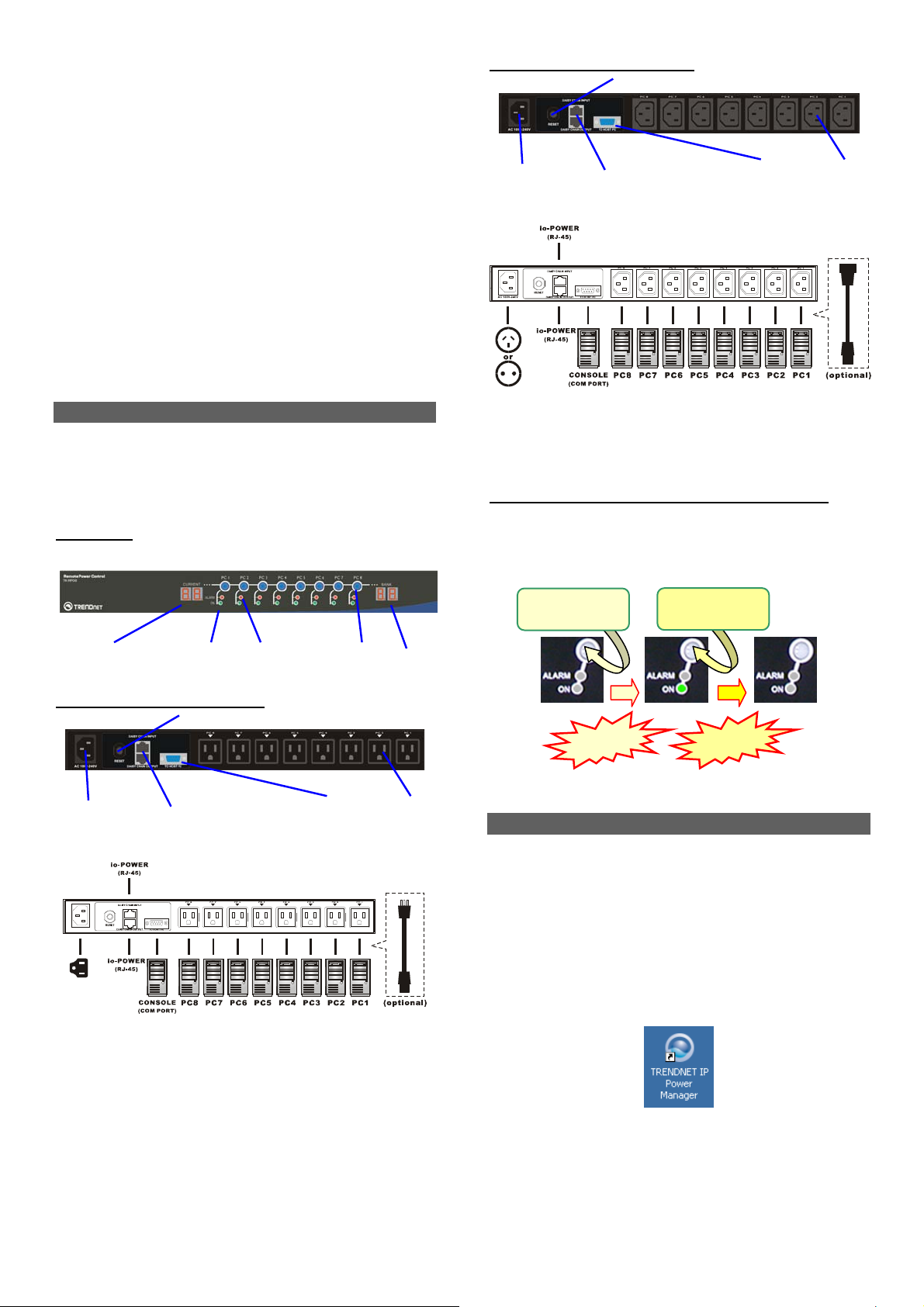
Front-panel
Current Loads Display
Rear panel – for the US Region
Alarm LED: (Red)
Power ON LED: (Green)
POWER Reset button
Power Button
Bank Number Display
Power Input
( IEC 320 C14 )
11-~240 Vac@60Hz
Daisy-chain port (RJ-45)
- Stack-in (upper)
- Stack-out (lower)
Serial port
(RS-232)
Power Output
(UL-498 5-15R)
Rear panel – for the EU Region
POWER Reset button
Power Input
( IEC 320 C14 )
11-~240 Vac
You might need to use extra adapter cords between TK-RP08 and
your devices, especially when the devices are not of the plug
specification that fits the standard power outlets on the back panel of
TK-RP08. These adapter chords are not included with your package
carton and are available by optional purchase.
“One-touch” Power ON/OFF via Front-panel Button
To power ON/OFF any connected device, simply press and
hold the corresponding Power Button for over 2 seconds to
toggle your device On and Off upon button release.
Press and hold
for 2 “ ….
Powered Off Powered-On Powered-Off
By default, each port is in powered-off state when TK-RP08
is powered on.
Daisy-chain port (RJ-45)
- Stack-in (upper)
- Stack-out (lower)
60Hz
Press and hold
for 2 “ ….
Serial port
(RS-232)
Release!
Release!
Power Output
(IEC 320 C13)
Install ioPower Management Software
Step 1. Insert the Support CD-ROM disc to your host PC
CD-ROM Drive. (or you can download the installer program
from available support website)
Step 2. The installer program will auto-run when you
insert the Support CD to your CD drive. (If not, then
double-click the installation program executable file to start
program installation.)
Step 3. Follow subsequent instructions to finish installation.
Step 4. After you have finished installation, you will see a
desktop icon and an TK-RP08 program group appears within the Programs menu.
(TK-RP08 Management Software)
Desktop Icon
2
Page 6
Connect host PC to ioPower
Now you can begin connecting your ioPower to the host
PC
Step 1. Run the TK-RP08 Management software by double-
clicking its desktop icon or access Start /programs
/ioPower/ioPower Management.
Step 2. Connect the host PC to TK-RP08 by clicking
Setting/Connect. And the software will automatically detect
COM port for TK-RP08 ….
Now get yourself a little bit familiar with the Management
Software interface ……….
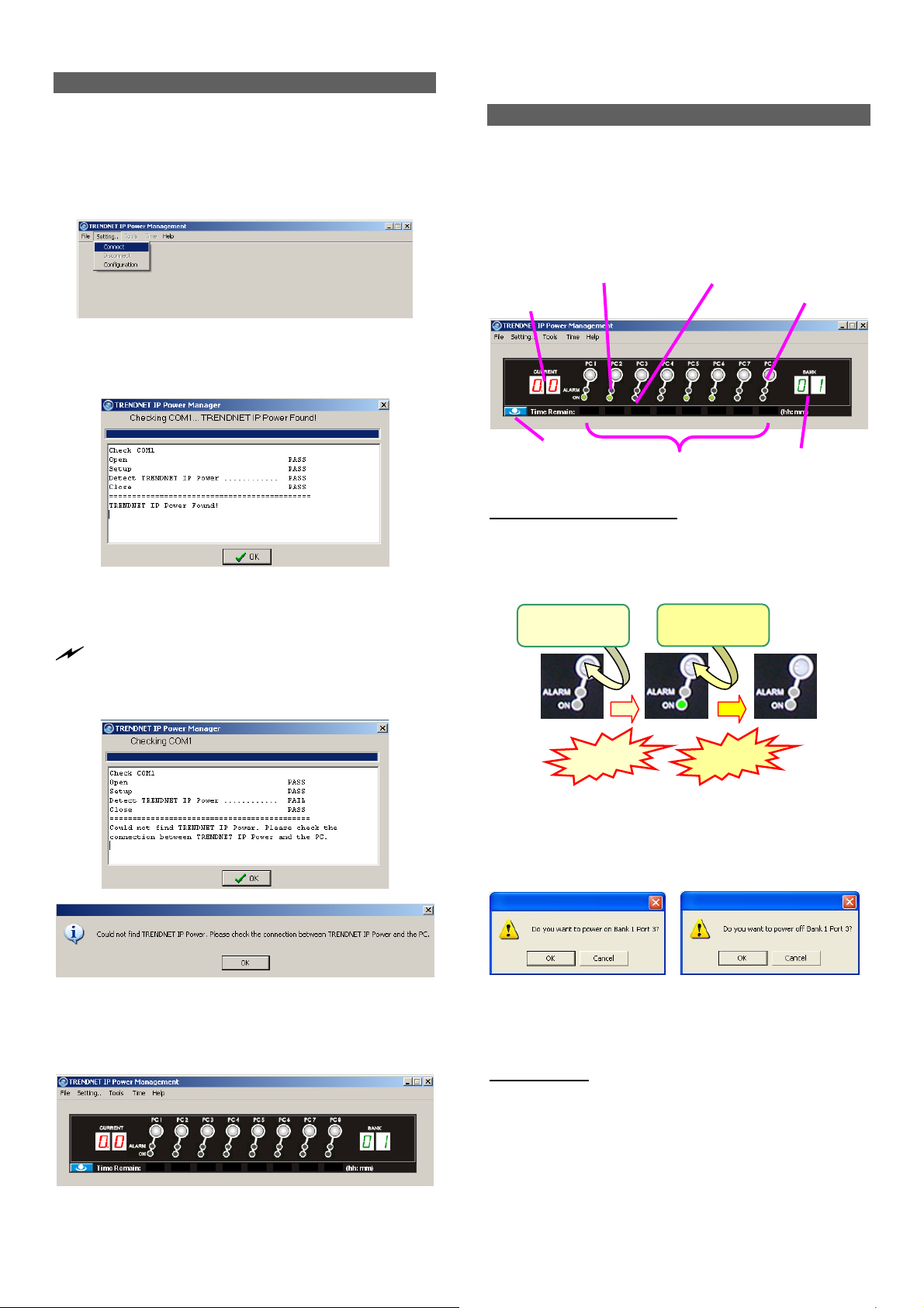
Power Management Software Interface
When running the TK-RP08 Management Software, you
should see a virtual front-panel identical to the physical front-
panel. If you are cascading multiple units of TK-RP08 (using
the RJ-45 daisy-chain interfaces connected by a UTP cable),
you can then see a corresponding number of stacked virtual
front-panels, each of which showing its bank number, the
total current loads and time remaining status per port.
Current Loads Display
Alarm LED (Red) Power ON LED (Green)
Power Button
Check the COM port detection message on the message
Box. After the COM port has been successfully detected,
click OK to connect.
Note that if you see the FAIL message such as in the following
picture, it means you have a faulty connection. Check your physical
COM port connection to make sure that everything is in place,
including the connectors and RS-232 cable integrity, etc.
Global Power Action Button
Virtual front-panels showing a single unit
Time Remain
Bank Number Display
Virtual front-panel operation
The virtual front-panel serves just like a real front-panel to
provide “one-touch” power on/off function. Just click each
virtual button to switch the power on and off
Press and hold
for 2 “ ….
Powered Off Powered-On Powered-Off
Release!
Press and hold
for 2 “ ….
Release!
However, to avoid accidental mistakes, TK-RP08
Management software will, by default, pop up a prompt for
confirmation of this change after you click the virtual power
button.
Failure of COM port detection
Step 3. Then you can see the virtual front panel of the
connected TK-RP08 unit(s).
Power on/off confirmation dialog prompt
User can have free choice to disable/enable the confirmation
prompt according one’s convenience.
Menu Function
File/Exit (Ctrl-X)
To exit the management program, click File/Exit or use the
hotkey, Ctrl-X.
Setting/Connect
When TK-RP08 is disconnected with host PC, click
Setting/Connect to connect to host PC.
3
Page 7

Setting/Disconnect
When TK-RP08 is connected with host PC, click
Setting/Disconnect to disconnect it from host PC.
Setting/Configuration
Click Setting/Configuration to access the TK-RP08
Configuration interface. You can use this dialog box to
configure your COM port setting, Auto-connection and Power
ON/OFF confirmation prompt setting.
The General Setting Tab
<Select COM port>: you can select Auto for auto-
configuration of COM port, or you can specify your COM port
setting as any of the available COM ports.
<Auto-connect to TK-RP08 on Start>: Check this option if
you want to automatically connect to TK-RP08 when the
management software is started. (Auto-connect is disabled
by default)
<Touch-Panel Power ON/OFF Confirmation Prompt>: Check
this option if you want a confirmation prompt pops up to
confirm the Power ON/OFF change with you. (Confirmation
Prompt is enabled by default).
<Auto-sync system time with host time on start>: Check this
option if you want to synchronize TK-RP08 system with PC
system time every time when you start ioPower Management
Software.
<Restore last known port status on start on start>: Check this
option if you want to restore the last known port status of
each port when TK-RP08 unit is restarted.
Tools/Upgrade
Once TK-RP08 firmware upgrade is available, you can either
get it from your local dealer or download it from available
network resources. First, copy the firmware upgrade file to
your host computer, and then access Tool/Upgrade to open
the file locator dialog box.
Then select the correct firmware upgrade file, e.g. TK-RP08
_V.x.x.x_dddddd.x Then click Open to start firmware
upgrade.
You can also use the Windows HyperTerminal to perform firmware
upgrade, please refer to the Firmware Upgrade Operation Guide that
comes with your firmware upgrade file. Normally, your TK-RP08
unit is loaded with the latest firmware, you should have no need to
reload/upgrade your firmware unless (1) there’s a new firmware
upgrade ready (2) your firmware is corrupted and need reloading.
Tools/Check Version
To check the firmware version of Bank x (x = 1 ~ 16) of
cascaded TK-RP08 units, just click Tools/Check
Version/Bank x to show the firmware version information in a
small message box.
Time/ Set Timer
On this Time/Set Timer setting, you can specify whichever
port on whichever bank (of all available banks) to power
on/off at a preset time point (within 23 hours 59 minutes) or
after certain duration (within 99 hours 59 minutes). After you
have hit the Apply button, the enabled settings will be
registered and put into action accordingly, and each entry
date/time will be shown.
4
Page 8

Tickers showing remaining time for power actions
(still more than 21 minutes to go for a Power-On on all ports)
Note that the timer settings will also be executed nonetheless
when (1) the host PC is shut down, or (2) the
Management Software is disconnected to the
ioPower unit will also retain the last known port status of each port
and will optionally restore each port to its last known status when
ioPower is powered on again. However, if the
has been powered down itself, it would lose all its previous
timer settings and need to be reconfigured or reloaded
with (previous) timer settings once again.
Note that if you use the timer function to power on/off your
device, the confirmation dialog prompt will not pop up for your
confirmation just as you use the virtual front-panel button. Since it is
assumed that you have intended to power on/off the specific device
as you have planned… Therefore, timer will go directly to power
on/off the device without warning you once the time is due.
When you input a value that is beyond the acceptable range of a
setting field, a warning prompt will appear to warn you for in correct
input.
TK-RP08. And the
TK-RP08
TK-RP08 Unit
The Timer Setting Tab
Just use the series of check boxes and drop down combo
boxes to specify the bank/port and time/duration for a power
on/off.
There are several timer setting modes for selection:
After … to specify power on/off after specific duration
At … to specify power on/off at preset time
Every day … to specify daily power on/off at preset time
Every week …to specify weekly power on/off at preset day & time
To validate a specific timer setting item, just check the
Enable checkbox and press Apply to validate them, and
press OK to save and exit.
To invalidate a specific timer setting item, just uncheck
the Enable check box, press Apply and then OK to save and
exit.
To set timer settings on Bank x, hit the Bank x tab to
select the specific timer setting page of Bank x, and then
configure the timer accordingly.
To clear all timer settings on Bank x, just hit the Clear
Bank x button and then hit Apply button to validate.
To save the timer settings on a bank to a file, just hit the
Save button to save the settings on your current bank into a
file.
To load timer settings of a bank from a file, just hit Load
button and find the timer setting file to load.
To clear all timer settings of all banks, just hit the Clear All
button, and then hit Apply button to validate.
After the timer setting is enabled for a specific port, you will
see a count down timer ticker under that specific port on the
virtual front-panel of your TK-RP08 Management Software
interface, and the alarm LED (red) will be flashing for a
reminder. When within one minutes to power action, the
ticker number will be flashing.
Range of hour settings Range of minute settings
Global Power Action Button
TK-RP08 also allows you to perform global Power ON/OFF
actions on all ports of a specific bank or of all cascaded
banks….
Click the Global Power Action button on the lower left of the
virtual touch panel will evoke a Quick Menu for global power
action such as power on/off all ports of a specific bank or all
banks.
Global Power Action Menu
On the Global Power Action Menu, you can choose the
following power on/off options:
• Power on all ports of a Bank x, x = 1~16
• Power off all ports of a Bank x, x = 1~16
• Power on all ports of all banks.
• Power off all ports of all banks.
Just select any of these options for simultaneous power
on/off all ports on a specific bank or on all banks, and a
confirmation prompt will appear to ask you for confirmation.
Click OK to validate the action you selected.
5
Page 9

The Confirmation Dialog Prompt
You can also access the timer setting interface on the Global
Power Action Menu as well as to check the firmware version
of any specific bank of the daisy-chained TK-RP08 units.
System Requirements
Operation
Mode
Used with a
Host PC
• a Win-based Host PC (with TK-RP08
Management Software installed)
• Serial (RS-232) Cable for connection with
host
• UTP cable (only for cascading multiple
units of ioPower)
Requirements
Specifications
Model Name
Input Voltage 100 ~ 240 VAC @ 50~60 Hz
Output Voltage 100 ~ 240 VAC @ 50~60 Hz
AC Output 8 total
Front-panel control 8 Power buttons
Host connection Serial RS-232 interface (DB-9)
User interface Host PC / ioPower Management
Cascade level Up to 16 units
Cascade interface RJ-45 (via UTP cable)
Max. current loads per port 6 amp per port
Current Overload
Protection
Operating Temperature 0~45°C
Operating humidity 10~90% RH
Storage Temperature -20 ~ 70°C
Storage Humidity 0~90% RH
Dimensions (L x W x H) 410 x 165 x 44.5 mm
TK-RP08
(Depending on power input)
Software
15 amp max.
Troubleshooting
An Alarm LED is Lit (Red)
In normal condition, the Alarm LED should never be lit.
However, when the Alarm LED is lit, it indicates that the
corresponding power output port is put out of function by a
hardware error, which prevents this port to power on or off.
If you see a lit Alarm LED, you should first disconnect the
device connected with it and then try to troubleshoot by
pressing several times its power button on the front-panel of
TK-RP08, to see if the Alarm LED still remains lit persistently.
If so, it indicates that this port is malfunctioning for good and
need technical service from your local dealer.
When a port is currently scheduled with a Timer setting for later
power on/off, its alarm LED (red) will be flashing for a reminder.
Also when you perform a firmware upgrade on
alarm LEDs will be flashing while it is still in process. In these
conditions, flashing red LEDs do not indicate a problem.
TK-RP08, all the
Current Overloads Warning - A Flashing Numerical LED
display (Red)
If the total current loads exceed 15 AMP-- the maximum
allowable current loads of TK-RP08 --the numerical display
of the current loads (Red) will be flashing. If you see the
flashing Numerical LED display, it means TK-RP08 is now
suffering form a current overloads. If that is the case, you
should try to shutdown some devices to keep the current
loads within its reasonable range.
Circuit Breaker Open Due to Current Overloads
If the total current loads exceed 15 AMP, the circuit breaker
device might be activated to physically break off the internal
circuit for safety and stop the function of TK-RP08. To restart
the unit, just press the Power Reset button on the back panel.
Firmware Upgrade Not Successful or Firmw are
Corrupted
If your firmware upgrade has not succeeded or your firmware
is somehow corrupted and could no longer function anymore,
your current loads LED display will show forth a message
such as “OP”. If you see such message on your current
loads display, please upgrade your firmware once more or
check the integrity of your firmware code.
Port Error (unable to power on) Port Error (unable to power off)
While an alarm LED is lit, the timer setting interface on your
TK-RP08 Management Software will also show forth the
“invalid” message and block all sequent setting possibility on
that malfunctioned port.
6
Page 10

Flash Upgrade Operation Guide
(Using Windows HyperTerminal)
Important Note: Besides using Windows HyperTerminal for TK-RP08 flash upgrade, you can also use the Tools/Upgrade
option on the IP Management Software Menu. Please refer to the Quick Installation section on this User Guide.
The TK-RP08 allows its user to upgrade firmware contents
whenever is needed to enhance its functionality and/or
performance. With the firmware upgrade feature, your
investment on the unit is further ensured and its life-time value
just maximized. You don’t have to buy a newer unit just to
have better features, instead you can have them all added to
your current unit with an easy flash upgrade! The correct Flash
upgrade procedure is described below. Please follow the
instructions to complete your firmware upgrade.
Flash Upgrade Procedure
Before you can perform a flash upgrade, you should have (1) a
powered-on PC with an available RS-232 port (DB9) (2) the TK-
RP08 Unit to be upgraded, and (3) a RS-232 cable (DB9 to-DB9)
connected already to RS-232 ports on both your PC and the ioPower
Unit.
AND also…..
Pease be sure to have (4) the latest flash upgrade file (
your local computer. You can copy them from the diskette/CD-ROM
provided by the technical support or download it from available
support website.
*.x
) ready on
Check the connection between the TK-RP08
Unit and PC
Click OK.
Step 3. Select COM 1 or COM 2 (depending on r actual COM
port configuration). In this case, we select COM 1.
Click OK.
Step 4. Configure your port setting with the following
parameters:
Bits per seconds: 9600
Data bits: 8
Parity: None
Stop bits: 1
Flow Control: Hardware
Make sure you have powered on the PC and also the
TK-RP08 Unit before you perform the flash upgrade
procedure.
Step 1. Connect your PC and the TK-RP08 Unit using a RS-
232 cable.
Setting the Windows HyperTerminal
Once you have successfully established a serial connection,
the settings will be stored on your PC and a shortcut with the
connection’s name generated under your HyperTerminal
program menu. Next time, you can establish the connection
again simply by clicking the connection shortcut without going
over the procedure in this section again. If that is the case, just
click the connection shortcut and go right to the last section,
Flash Upgrade File Transfer
Step 2. On your PC (which should already be connected to
your ioPower Unit with a DB9-to-DB9 RS-232 cable),
activate the Windows HyperTerminal
(Start/Programs/Accessories/Communications/Hyper
Terminal). Designate your HyperTerminal connection
with a specific name, e.g. Power Control 01.
.
Click Apply then click OK. Then HyperTerminal
windows appears…..
Step 5. Hit Enter key twice to go into command mode …..
7
Page 11

Flash Upgrade File Transfer
Step 7. To start loading the file, access the drop-down menu
on HyperTerminal: Transfer/Send Text File….
If the firmware version is lower than 040421, here you
should type in /
then hit
On the HyperTerminal window, you’ll see the Testing
OK message and the existing firmware version
number…..
Step 6. Type Upgrade on the command line and hit
Enter…Now you have your HyperTerminal ready for
file transfer. Keep your HyperTerminal window open
and go to the next step….
TK-RP08 \ on the command line and
Enter
to go into command mode.
….and a dialog box will prompt you to select the flash
upgrade file, *.x (with a file extension name as .x). In
this case, we have our flash upgrade file as TK-RP08
3.0.1_040907.x (it could be any other file name with
an .x extension!). Note that since it has an extension
name other than .txt, we have to select the “All file
[*.*]” option in order to see it on the file listing…
Then select our target file: PowerGate.hex.bin.x. And
then Click Open to begin the file transfer …..
When the file transfer is completed, you will see the
message: OK!! Please Restart on the HyperTerminal
window to tell you that Flash Upgrade process is
successful….
8
Page 12

Troubleshooting
If the flash upgrade procedure seems never ending or you
see the following message:
Please send new firmware
the screen, it indicates that the flash process had failed. If that is
the case, please power off the TK-RP08 Unit and then power it
on restart the whole flash procedure again. You also press any
button on front panel about 3 seconds when you power on the
TK-RP08 Unit.
, shown on
Step 8. After you have successfully upgraded the flash
firmware and before you utilize the TK-RP08 Unit,
you should perform a system reset by powering
down the unit. Wait for a few seconds and then
complete the reset again.
9
Page 13

Install the TK-RP08 as a Power Control
Accessory for the TK-IP101 Switch
The TK-RP08 can be used as a power control accessory for
TK-IP101 Swtich, or any other KVM Switch that supports
a standard serial power control.
When used in conjunction with power device or KVM, you
have to properly connect the TK-RP08 to the TK -IP101 via
a serial interface connection, using the special serial cable
that comes with your TK-IP101. Further, you have to
correctly configures the setting on the TK-IP101, in order
to enable the remote power control function that can be
effected via the viewer menu interface on any of the
remote connection client computers.
I. Connect TK-RP08 to TK-IP101
Before you connect the TK-RP08 to the TK-IP101, you might need to
install them first into their own proper placements within a rack,
that is , if you are going to use them within a rack. After you have
installed the TK-RP08, TK-IP101 into the rack, or into their proper
locations, you can now proceed with following steps for further
connections.
Step 1. Use the serial power control cable that comes
with your TK-IP101 package to connect the TKRP08 serial interface to the serial port on the
backpanel of the TK-IP101.
TK-IP101 back panel
TK-RP08 Backpanel
Serial power control cable
(can be found within the TKIP101 package)
Trendnet KVM back panel
TK-RP08 Backpanel
Step 2. Make sure that the TK-IP101 and TK-RP08 are
powered on. If not, power them up first before
proceeding.
Next, you should access the TK-IP101 Web management
interface to set up the various power control settings….
II. Enable the Power Control Feature on
TK-IP101 Web Management Interface
Step 3. Access the Web Management Interface of your
TK-IP101.
And from there, you can then go forth to (1) enable the
power control feature of TK-IP101, and then (2) configure the
Power control commands for each and every port on the TKRP08. (
KVM Server/Power Control – Enable the power control.
Step 4. Go to the Power Control page. Then Enable and
The Power Control page allows you to enable or disable the pow er
control feature via the serial po rt on the back pan el o f you r TK-IP 101.
(Also please refer toTK-IP101 User Guide, Section 4.11, KVM
Server/Power Control – Enable the power control.)
Also please refer to TK-IP101 User Guide, Section 4.11,
Select various Power Control features.
Serial power control cable
(can be found within the TKIP101 package)
)….
A real connection case of TK-RP08
and TK-IP101
10
Page 14

Configure the Power Control Command
for each and every port on the TK-IP101
Step 6. Go to the KVM Server/Computers page.
Step 5. Check the Enabled option to activate the remote
power control support feature of the back panel serial
port of the TK-IP101.
Once the
Enabled
option is checked, a subsequent
Power Device Login option will appear for you to decide
whether to enter the login script. The TK-RP08 does not
require a login script. Hence you don’t have to enter any
script.
Other options:
Simple Users Can Control Power
Check this box if you want that simple users be able to power on and power
off the computers. By default, the TK-IP101 allows only Super admin and
admin the right to power on/off the computer from the viewer Quick Menu.
If you want to allow this feature to simpler users, you can check this option.
Power Device Login
Depending on the Serial Power control device you used behind TK-IP101,
sometimes you will need a login script to login or initialize your power
control device. If that is the case, just check the Power Device Needs a
Login option, and a Login Dialog field will appear for you to enter your
login script. In this case, you don’t have to enter any script, since TK-RP08
does not need any.
After you have made all modifications, click Store Settings
to save your settings and then hit Apply Settings/Restart
Servers to validate these new settings. Every change you
have made on this page will NOT apply until you hit Apply
Settings/Restart Servers!
The various settings on this page are KVM port-specific
because a computer is first identified by the KVM port it is
attached to. Select the target port on which your subseq uent
settings on this page are directed. You can use the dropdown combo box as well as use the Previous and the Next
button to navigate to a specific port.
Important Note: when using a power control device,
please note that some newer computers will require some
BIOS option adjustment to restart when power is coming
back. Otherwise they will not restart without a push of the
computer power button. Usually, you should enable the
Power Loss Restart
similar option depending on the BIOS vendor), so that your
option on your computer BIOS (or
computer can boot up when the power control device is
feeding power again
.
Step 6-1. Configure the Power down and Power On
command for each and every port on the IP KVM Switch.
First, you select the 1
st
port and configure the Power Down
and Power Off command, (and if necessary the delay time
between the Power Off and Power On Command, or you can
leave it as default) then hit the Store Settings buttons. Then,
you go the 2
nd
port and then do the configurations likewise,
then hit the Store Settings button. …. So you configure
every port right through to the last port of your IP KVM
switch, and then hit the Store Settings button. Then you hit
the Apply Settings button to make the changes effective.
Power down command: /Fbbp\
F: OFF
bb: 2-digit bank number on which the target port resides.
p: 1-digit target port number.
e.g. If you want to turn off port 3 on bank 1. Then you have
to enter:
/F013\
Power on command: /Obbp\
O: ON
bb: 2-digit bank number on which the target port resides.
p: 1-digit target port number.
11
Page 15

e.g. If you want to turn on port 3 on bank 1. Then you have
to enter:
/O013\
Delay
Here you should specify the delay time between the send ing
of power-down and power-on commands to complete a
power cycling. A power cycling is processed only if you
have selected Restart Computer into the Alarm page. By
default this delay is 5 seconds.
Important Note: To remotely power on/ off this
computer from the Windows or the Java Viewers, switch to
this computer and then click
Power On/Power Off
in the
Viewer menu. The command specified here will be sent
automatically by TK-IP101 to the TK-RP08.
After you have made all modifications, click Store Settings to save
your settings and then hit Apply Settings/Restart Servers to validate
these new settings. Every change you have made on this page will
NOT apply until you hit Apply Settings/Restart Servers! (Also refer
to TK-IP101 User Guide, Section 4.10, KVM Server/Computers –
Port and IP settings)
Verify the remote Power Control function
via Viewer Quick Menu
Step 7. On a client computer that has been installed with
the TK-IP101 viewer program, you can then make a
viewer connection to the TK-IP101.
Step 7-3. To power on or power off a specific computer
desktop of your choice, you need only to select the
Power On /Power Off option on the Viewer Quick Menu.
For viewer connection details, please refer to Chapter 4, Unit
Management over a secure https browser connection.
Step 7-1. To power off a specific computer, first you
have to switch to that computer desktop by clicking its
icon in the Select Computer Box to switch to whatever
PC you WAN to perform power on/off from remote.
Step 7-2. Access the Viewer Quick Menu by clicking on
the title bar of the viewer window.
Now you can use the Viewe Quick Menu to perform power
on / power off command remotely across internet by using
the TK-IP101 together with an TK-RP08.
Likewise, if you are using any other IP KVM switch that supports
serial interface, then you can configure it according to its manual
instructions.
12
Page 16

Serial Command Set
Before you use the serial command …
(1) To use the serial commands for TK-RP08 control, you have to establish a HyperTerminal
connection between TK-RP08 and the host PC, using a RS-232 cable for connection. Use
the following parameters for HyperTerminal connection:
Bits per seconds: 9600
Data bits: 8
Parity: None
Stop bits: 1
Flow Control: Hardware
(2) After your HyperTerminal session has been established, you have to hit the Enter key twice
to go into command mode, then you can input the serial commands within the HyperTerminal
window according to the following command usages ………………
Command usage notes:
1. The commands are NOT case-sensitive. That means you can use lower case in typing
your commands! The commands does not require a strict double-digit entry of bank number
or port number (such as ON 01 03 – Power on bank 1 port 3) but can accept their singledigit entries (such as ON 1 3), and also allow multiple blank spaces in between its
command parameters (such as ON 1 3).
2. When using the HyperTerminal, note that ScrollLock should not be ON. Otherwise, it
will block you from entering commands. ScrollLock is OFF by default in HyperTerminal.
However, if you cannot type in commands, please check the ScrollLock status, which can
be viewed on status bar at the bottom of your HyperTerminal window. If ScrollLock is ON,
hit ScrollLock key again to relieve it.
HELP – Show Help Menu
[Description]Show the Help Menu on the HyperTerminal screen
[Usage] HELP
[Example] Help
? - Show Help Menu
[Description]Show the Help Menu on the HyperTerminal screen
[Usage] ?
[Example]
?
QUIT - Exit serial command mode
[Description] exit serial command mode
[Usage] QUIT
[Example]
QUIT
Notes: Once you exit serial command mode, you have to hit Enter twice again to enter
the serial command mode again.
13
Page 17

ON – Power ON
[Description]Power on one/all AC outlet port(s) immediately
[Usage] ON [bank_number] [port_number]
[Examples]
ON 1 4 – Power on port 4 on bank 1 immediately
ON 1 0 – Power on all ports on bank 1 immediately
ON 0 0 – Power on all ports on all cascaded banks immediately
Notes:
1. A port number of 0 represents all ports; while a bank number of 0 represents all
cascaded banks.
2. The command: ON 0 x ………, x = 1~9, is not valid.
OF – Power OFF
[Description]Power off one/all AC outlet port(s) immediately
[Usage] OF [bank_number] [port_number]
[Examples]
OF 1 4 – Power off bank 1 port 4 immediately
OF 1 0 – Power off bank 1 all ports immediately
OF 0 0 – Power off all ports on all cascaded banks immediately
Notes:
1. A port number of 0 represents all ports; while a bank number of 0 represents all
cascaded banks.
2. The command: OF 0 x ………, x = 1~9, is not valid.
TA – Timer Activate at specific time point
[Description]Set the timer to turn on/off a specific port at specific time
[Usage] TA [bank_number] [port_number] [ON | OF] [Time_point]
[Examples]
TA 1 4 ON 01:22:50 – Set timer to power on port 4 on bank 1 exactly
at 01:22:50.
TA 1 0 ON 00:10:00 – Set timer to power on all ports on bank 1 exactly
at 00:10:00
TA 0 0 OF 01:00:00 – Set timer to power off all ports on all cascaded
banks at 01:00:00
Notes:
1. A port number of 0 represents all ports; while a bank number of 0 represents all
cascaded banks.
2. The command: TA 0 0x ………, x = 1~9, is not valid.
3. The system time should be calibrated before use for the first time.
TF – Timer Activate after specific time duration
[Description]Set the timer to turn on/off a specific port after specific time duration
[Usage] TF [bank_number] [port_number] [ON | OF] [Time_duration]
[Examples]
TF 1 4 ON 03:25:56 – Set timer to power on port 4 on bank 1 exactly
after 3 hour 25 minutes and 56 seconds.
TF 1 0 ON 00:10:00 – Set timer to power on all ports on bank 1 exactly
after 10 minutes
TF 0 0 OF 01:00:00 – Set timer to power off all ports on all cascaded
banks after 1 hour.
Notes:
1. A port number of 0 represents all ports; while a bank number of 0 represents all
cascaded banks.
2. The command: TF 0 0x ………, x = 1~9, is not valid.
14
Page 18

ED – Timer Activate everyday at a specific time point
[Description]Set the timer to turn on/off a specific port every day at specific time
point
[Usage] ED [bank_number] [port_number] [ON | OF] [Time_point]
[Examples]
ED 1 4 ON 02:12:20 – Set timer to power on port 4 on bank 1 exactly
every day at 02:12:20.
ED 1 0 ON 00:10:00 – Set timer to power on all ports on bank 1 exactly
every day at 00:10:00.
ED 0 0 OF 01:00:00 – Set timer to power off all ports on all cascaded
banks every day at 01:00:00.
Notes:
1. A port number of 0 represents all ports; while a bank number of 0 represents all
cascaded banks.
2. The command: ED 0 0x ………, x = 1~9, is not valid.
EW – Timer Activate every week at a specific time point
[Description]Set the timer to turn on/off a specific port every week at specific time
point
[Usage] EW [bank_number] [port_number] [ON | OF] [day] [Time_point]
[Examples]
EW 1 4 ON 1 01:22:50 – Set timer to power on port 4 on bank 1 exactly
every Monday at 01:22:50..
EW 1 0 ON 3 00:10:00 – Set timer to power on all ports on bank 1 exactly
every Wednesday at 00:10:00.
EW 0 0 OF 5 01:00:00 – Set timer to power off all ports on all cascaded
banks every Friday at 01:00:00.
Notes:
1. A port number of 0 represents all ports; while a bank number of 0 represents all
cascaded banks.
2. The command: EW 0 0x ………, x = 1~9, is not valid.
3. A day of 0 represents Sunday; while a day of 1 represents Monday, later calculate
for this reason.
TQ – Timer Quit
[Description]Cancel a specific/all timer setting(s)
[Usage] TQ [bank_number] [port_number] [ON | OF]
[Examples]
TQ 1 4 ON – Cancel timer power-on setting on port 4 of bank 1
TQ 1 4 ON – Cancel timer power-on setting on port 4 of bank 1
TQ 0 4 - Cancel timer power-on&off setting on port 4 of bank 1
TQ 1 0 OF - Cancel timer power-off setting on all port of bank 1
TQ 0 0 ON - Cancel timer power-on setting on all port of all banks
TQ 0 0 - Cancel timer power-on&off setting on all port of all banks
Notes:
1. A port number of 0 represents all ports; while a bank number of 00 represents all
cascaded banks.
2. The command: TQ 0 x ………, x = 1~9, is not valid.
3. If you have not specified either “ON” or “OF” as the command parameter, it is
assumed that this Timer Quit directive will be directed on both the Power-ON and PowerOFF setting of that specific port.
15
Page 19

ST – Status
[Description]Show the system status of a specific bank, such as current loads, on/off
status and timer settings
[Usage] ST [bank_number]
[Examples]
ST 1 – Show the system status of bank 1
ST 16 – Show the system status of bank 16
ST 0 – Show the system status of all banks
UPGRADE – Upgrade Firmware
[Description]Upgrade the system firmware
[Usage] UPGRADE
[Example]
UPGRADE
Note: Please also refer to ioPower Flash Operation Guide for details.
SETTIME – Set Up System Date and Time
[Description]Set up the system date and time
[Usage] SETTIME [20yy/mm/dd] [hh:mm:ss]
[Example]
SETTIME 2004/09/27 18:10:00 – Set up the system Date and time to be 2004/09/27 18:10:00
GETTIME – Get System Time
[Description]Show the system date, day and time
[Usage] GETTIME
[Example]
GETTIME
VER – Firmware Version
[Description]Show the firmware version of a specific bank.
[Usage] VER [bank_number]
[Example]
VER 01 – Show the firmware version of bank 1
VER 16 – Show the firmware version of bank 16
VER 00 – Show the firmware version of all bank
16
Page 20

17
 Loading...