


© Copyright 2020 TRENDnet. All Rights Reserved.
TRENDnet User’s Guide
Table of Contents
i
Contents
Product Overview ........................................................................... 1
TI-RP262i ........................................................................................................................ 1
Package Contents ................................................................................................ 1
TI-PG102i ....................................................................................................................... 5
Non-PoE ......................................................................................................................... 8
TI-G642i ......................................................................................................................... 8
TI-G102i ....................................................................................................................... 11
TI-G160WS ................................................................................................................... 14
TI-G160i ....................................................................................................................... 17
Switch Installation ........................................................................ 20
DIN-Rail Installation ..................................................................................................... 20
Install power supply connections ................................................................................ 21
SFP Transceiver/Optical Cable Installation .................................................................. 21
Basic IP Configuration .................................................................................................. 22
Connect additional devices to your switch .................................................................. 23
Accessing switch management interfaces ...................................... 24
Access your switch command line interface................................................................ 24
CLI Command Modes ......................................................................................... 24
Access your switch web management page ................................................................ 26
System Information....................................................................... 27
Basic Settings ................................................................................ 28
General Settings .......................................................................................................... 28
System ............................................................................................................... 28
Jumbo Frame ..................................................................................................... 29
SNTP ................................................................................................................... 30
Management Host ............................................................................................. 32
MAC Management ...................................................................................................... 34
Static MAC Settings............................................................................................ 34
Age Time Settings .............................................................................................. 36
MAC Table ......................................................................................................... 36
Port Mirror ................................................................................................................... 37
Port Settings ................................................................................................................ 39
General Settings ................................................................................................ 40
Information ........................................................................................................ 42
Advanced Settings ........................................................................ 43
Bandwidth Control ...................................................................................................... 43
QoS .................................................................................................................... 43
Rate Limitation .................................................................................................. 49
IGMP Snooping ............................................................................................................ 52
IGMP Snooping .................................................................................................. 52
Multicast Address .............................................................................................. 55
VLAN ............................................................................................................................ 58
Port Isolation ..................................................................................................... 58
802.1Q VLAN ...................................................................................................... 59
MAC VLAN ......................................................................................................... 63
DHCP Options .............................................................................................................. 64
DHCP Relay .................................................................................................................. 67
EEE (Energy Efficient Ethernet) .................................................................................... 70
ERPS (Ethernet Ring Protection Switching) ................................................................. 71
Link Aggregation .......................................................................................................... 75
Loop Detection ............................................................................................................ 80
Modbus ........................................................................................................................ 82
Power over Ethernet ................................................................................................... 86
STP ............................................................................................................................... 91
Security ...................................................................................... 100

© Copyright 2020 TRENDnet. All Rights Reserved.
TRENDnet User’s Guide
Table of Contents
ii
IP Source Guard ......................................................................................................... 100
Binding Table ................................................................................................... 105
ARP Inspection ................................................................................................. 107
Filter Table ....................................................................................................... 109
Access Control List (ACL) ............................................................................................ 110
802.1x ........................................................................................................................ 114
Port Security .............................................................................................................. 119
Monitor ...................................................................................... 121
Alarm ......................................................................................................................... 121
Port Statistics ............................................................................................................. 121
Port Utilization ........................................................................................................... 122
RMON Statistics ......................................................................................................... 123
SFP Information ......................................................................................................... 123
Traffic Monitor ........................................................................................................... 124
Management .............................................................................. 126
SNMP ......................................................................................................................... 126
SNMP Trap ....................................................................................................... 128
Auto Provision ........................................................................................................... 129
Mail Alarm ................................................................................................................. 130
Maintenance.............................................................................................................. 133
System Log ................................................................................................................. 136
User Account ............................................................................................................. 136
Device Management.................................................................................................. 138
Toplogy Map .............................................................................................................. 142
Technical Specifications .............................................................. 143
TI-PG541i ................................................................................................................... 143
TI-PG102i ................................................................................................................... 148
TI-G642i ..................................................................................................................... 151
TI-G102i ..................................................................................................................... 154
TI-G160WS ................................................................................................................. 157
TI-G160i ..................................................................................................................... 160
Troubleshooting ......................................................................... 163
Appendix .................................................................................... 164

© Copyright 2020 TRENDnet. All Rights Reserved.
TRENDnet User’s Guide
Managed Industrial L2 Switches
1
Product Overview
TI-RP262i
Package Contents
In addition to your switch, the package includes:
• Quick Installation Guide
• Console cable (RJ-45 to RS-232)
• Rackmount Kit
If any package contents are missing or damaged, please contact the retail store, online
retailer, or reseller/distributor from which the product was purchased.
TRENDnet’s Industrial Gigabit L2 Managed PoE+ Rackmount Switch Series offers
advanced layer 2 managed features with enhanced traffic controls to meet the evolving
demands of today’s SMB networks. Each industrial layer 2 rackmount switch is equipped
with an IP30 rated metal enclosure, designed to withstand a high degree of vibration
and shock, while operating within a wide temperature range of -40° – 70° C (-40° – 158°
F) for industrial environments. Our industrial layer 2 rackmount switch models feature
copper gigabit ports for high-speed device connections, as well as SFP slots that support
100/1000Base-FX SFP modules for long distance fiber networking applications. These
industrial layer 2 rackmount switches feature a fanless design that eliminates operating
noise and lowers energy consumption.
These Industrial Gigabit L2 Managed PoE+ Rackmount Switch Series provides an intuitive
web-based management interface. Each TRENDnet industrial layer 2 rackmount switch
supports advanced traffic management controls, troubleshooting, and SNMP
monitoring. Advanced managed switch features include LACP to group ports together
and increase bandwidth between switches, VLANs for segmenting and isolating virtual
LAN groups, QoS to prioritize traffic, port bandwidth controls, SNMP monitoring, and
more, making each TRENDnet industrial layer 2 rackmount switch a powerful solution
for SMB networks.

© Copyright 2020 TRENDnet. All Rights Reserved.
TRENDnet User’s Guide
Managed Industrial L2 Switches
2
Front View
Rear View
• LED Indicators – Indicators on the left display ALM, PWR, and POST status.
LEDs on each port show the status of the port based on the mode selected
using the Mode Button.
• Mode Button – Press the mode button to change the left LED indicator on each
port to display Speed, or PoE Mode. When button is depressed it will display
PoE, when not pressed it will indicate if 1000Mbps.
• Gigabit Ethernet PoE+ Ports (1-24) – Connect either network PoE+ or non-PoE
devices.
• Reset Button – Press and hold the button for less than 5 seconds to reboot, or
more than 5 seconds to reset to factory default.
• SFP Slots (25-26) – Supports optional 1000BASE-SX/LX mini-GBIC modules for
uplink or downlink connections.
• Console Port – The console port is a female RJ-45, use the included RJ-45 male
to RS-232 serial DB-9 female console cable.
• Power Terminals – Using proper gauge wire, terminate the leads from your
power supply to these power terminals to power your switch.
LED Indicators
• Ports 1-4 – Designed to operate at 10Mbps, 100Mbps, or Gigabit speed in both
half-duplex and full-duplex transfer modes. Supports Auto MDI-X and capable
of delivering up to 30W (802.3at PoE+) per port.
• Port 5 - Designed to operate at 10Mbps, 100Mbps, or Gigabit speed in both
half-duplex and full-duplex transfer modes. Supports Auto MDI-X
• SFP Slot 6 – Designed to operate at Gigabit speeds.
• Reset/Reboot Button – Push the button for 10 seconds and release to reset the
switch to factory defaults. Push the button for 3 seconds and release to reboot.
• Grounding point/screw – The switch chassis can also be connected to a known
ground point for additional safety and protection. (grounding wire not
included)
Note: For any unused ports or SFP slots, it is recommended to leave the rubber plugs
installed during operation.
LED
State
Status
PWR
(Green)
ON
When the PWR LED is on, the device is using the primary
power input source.
OFF
Primary power input source is off, disconnected, or has
failed.
RPS
(Green)
ON
When the RPS LED lights on, the device is using the
redundant power input source.
OFF
Redundant power input source is off, disconnected or has
failed.
ALM
(Red)
ON
Indicates alarm has been triggered on DIP switch settings and
signal sent out through ALM terminals on terminal block to
third party alarm device.
OFF
No alarm triggered.
POST
(Green)
ON
Device is ready and completed boot process.
OFF
Device is not ready.
SFP Slot 6
(Green)
ON
SFP link is connected.
BLINKING
Data is transmitting/receiving.
OFF
SFP link is disconnected.
PoE Ports 1-4
(Green)
ON
PoE supplied to Ethernet port.
OFF
No PoE supplied to Ethernet port.
Ports 1-5
1000M
(Green)
10/100M
(Off)
ON
Ethernet port is connected.
BLINKING
Data is transmitting/receiving.
OFF
Ethernet port is not connected.

© Copyright 2020 TRENDnet. All Rights Reserved.
TRENDnet User’s Guide
Managed Industrial L2 Switches
3
Top View
DC Jack Input for External Power Adapter
The device includes a DC Jack for an external power adapter and can
also be used as an additional redundant power supply (RPS) input.
Please ensure that the external power adapter is supplying 48VDC @
120W or above. 130W for max. PoE+ power. Please note power
adapter is sold separately (model: 48VDC3000)
*Please note power supply is sold separately*
**Supported power supplies: TI-S12024 (120W), TI-S24048 (240W), TI-S48048 (480W).
Lower wattage power supplies may be used but may result in decreased PoE power
budget**
6-pin Removable Terminal Block
Input/Ouput
Function
PWR Input
(+) & (-)
Connects primary power source (ex. external power supply) to power the
device. Device will obtain power from this input first priority if available.
Please make sure to power supplies are turned off before wiring in.
Use a flat-head screw driver to push the orange notches in order release
the wiring connections. While holding in released position, insert the
wiring into the connection inputs from the external power supply and
release the orange notch to lock in the wire connections.
Please ensure that the external power supply is supplying within the
range of 48VDC ~ 57VDC @ 120W or above. 130W for max. PoE+ power.
Please note power supply is sold separately (model: TI-24048)
Device supports overload current protection and reverse polarity
protection.
RPS Input
(+) & (-)
Connects redundant power source (ex. external power supply) to power
the device. Device will obtain power from this input secondary priority if
primary power input is not available or has failed.
Please make sure to power supplies are turned off before wiring in.
Use a flat-head screw driver to push the orange notches in order release
the wiring connections. While holding in released position, insert the
wiring into the connection inputs from the external power supply and
release the orange notch to lock in the wire connections.
Please ensure that the external power supply is supplying within the
range of 48VDC ~ 57VDC @ 120W or above. 130W for max. PoE+ power.
Please note power supply is sold separately (model: TI-24048)
Device supports overload current protection and reverse polarity
protection.
ALM Output
Connects external alarm and sends output signal if fault is detected
based on DIP switch settings.
Supports an output with current carrying capacity of 1A @ 24V DC.
DIP Switches
Reset Button
(bottom of unit)
Ground point
6-pin terminal
block (PWR,
RPS, ALM)
DIP switch
definition
DC Jack
(optional, see below)

© Copyright 2020 TRENDnet. All Rights Reserved.
TRENDnet User’s Guide
Managed Industrial L2 Switches
4
ALM DIP Switches
DIP No
Name
State
Status
1
PWR
ON
Primary power input source alarm trigger enabled.
OFF
Primary power input source alarm trigger disabled.
2
RPS
ON
Redundant power input source alarm trigger enabled.
OFF
Redundant power input source alarm trigger disabled.

© Copyright 2020 TRENDnet. All Rights Reserved.
TRENDnet User’s Guide
Managed Industrial L2 Switches
5
TI-PG102i
Front View
• PoE+ Ports 1-8 – Designed to operate at 10Mbps, 100Mbps, or Gigabit speed in
both half-duplex and full-duplex transfer modes while simultaneously providing
power to supported PoE devices. Supports Auto MDI-X.
• SFP Slot 9-10 – Designed to operate at Gigabit or 100Mbps speeds.
• Reset Button – Push the button for 5-10 seconds and release to reset.
• Grounding point/screw – The switch chassis can also be connected to a known
ground point for additional safety and protection. (grounding wire not
included)
LED Indicators
PoE+ Gigabit
RJ-45 ports
10/100/1000
Mbps per port
LED indicator
LINK/ACT per
port LED
indicator
IP30 Rated
Housing
PoE LEDs
SFP+ Slots

© Copyright 2020 TRENDnet. All Rights Reserved.
TRENDnet User’s Guide
Managed Industrial L2 Switches
6
Top View
*Please note power supply is sold separately*
**Supported power supplies: TI-S12024 (120W), TI-S24048 (240W), TI-S48048 (480W).
Lower wattage power supplies may be used but may result in decreased PoE power
budget**
6-pin Removable Terminal Block
Note: Turn off the power before connecting modules or wires.
Calculate the maximum possible current in each power wire and common wire. Observe
all electrical codes dictating the maximum current allowable for each wire size. If current
go above the maximum ratings, the wiring could overheat, causing serious damage to
your equipment.
Input/Output
Function
PWR Input
(+) & (-)
Connects primary power source (ex. external power supply) to power the
device. Device will obtain power from this input first priority if available.
Please make sure to power supplies are turned off before wiring in.
Use a flat-head screw driver to push the orange notches in order release
the wiring connections. While holding in released position, insert the
wiring into the connection inputs from the external power supply and
release the orange notch to lock in the wire connections.
Device supports overload current protection and reverse polarity
protection.
RPS Input
(+) & (-)
Connects redundant power source (ex. external power supply) to power
the device. Device will obtain power from this input secondary priority if
primary power input is not available or has failed.
Please make sure to power supplies are turned off before wiring in.
Use a flat-head screw driver to push the orange notches in order release
the wiring connections. While holding in released position, insert the
wiring into the connection inputs from the external power supply and
release the orange notch to lock in the wire connections.
Device supports overload current protection and reverse polarity
protection.
ALM Output
Connects external alarm and sends output signal if fault is detected
based on DIP switch settings.
Supports an output with current carrying capacity of 1A @ 24V DC.
DIP Switches
Reset Button
Ground point
6-pin terminal
block (PWR,
RPS, ALM)
DIP switch
definition

© Copyright 2020 TRENDnet. All Rights Reserved.
TRENDnet User’s Guide
Managed Industrial L2 Switches
7
ALM DIP Switches
Switch
Status
Function
1
OFF
Disable alarm relay for PWR power input
ON
Enable alarm relay for power failure on PWR power input
2
OFF
Disable alarm relay for RPS power input
ON
Enable alarm relay for power failure on RPS power input
3
OFF
Storm control managed by switch configuration
ON
Enable storm control (Broadcast and DLF rate set to 300pps)
Takes precedence over storm control switch configuration
4
OFF
802.1p QoS managed by switch configuration
ON
Enable 802.1p QoS on ports 1 and 2 (Set CoS priority to tag 4
on ports 1 and 2)
Takes precedence over 802.1p QoS switch configuration
5
OFF
Port 9 SFP set to Gigabit speed full duplex
ON
Port 9 SFP set to 100Mbps speed full duplex
6
OFF
Port 10 SFP set to Gigabit speed full duplex
ON
Port 10 SFP set to 100Mbps speed full duplex

© Copyright 2020 TRENDnet. All Rights Reserved.
TRENDnet User’s Guide
Managed Industrial L2 Switches
8
Non-PoE
TI-G642i
Front View
• Ports 1-4 – Designed to operate at 10Mbps, 100Mbps, or Gigabit speed in both
half-duplex and full-duplex transfer modes. Supports Auto MDI-X.
• SFP Slot 5-6 – Designed to operate at Gigabit speeds.
• Reset Button – Push the button for 3 seconds and release to reset to factory
defaults.
• Grounding point/screw – The switch chassis can also be connected to a known
ground point for additional safety and protection. (grounding wire not
included)
LED Indicators
Gigabit
RJ-45 ports
10/100/1000
Mbps per port
LED indicator
LINK/ACT per
port LED
indicator
IP30 Rated
Housing
Gigabit
SFP Slots

© Copyright 2020 TRENDnet. All Rights Reserved.
TRENDnet User’s Guide
Managed Industrial L2 Switches
9
Top View
*Please note power supply is sold separately*
**Supported power supplies: TI-M6024, TI-S12024 (120W), TI-S24048 (240W) **
6-pin Removable Terminal Block
Note: Turn off the power before connecting modules or wires.
Calculate the maximum possible current in each power wire and common wire. Observe
all electrical codes dictating the maximum current allowable for each wire size. If current
go above the maximum ratings, the wiring could overheat, causing serious damage to
your equipment.
Input/Output
Function
PWR Input
(+) & (-)
Connects primary power source (ex. external power supply) to power the
device. Device will obtain power from this input first priority if available.
Please make sure to power supplies are turned off before wiring in.
Use a flat-head screw driver to push the orange notches in order release
the wiring connections. While holding in released position, insert the
wiring into the connection inputs from the external power supply and
release the orange notch to lock in the wire connections.
Device supports overload current protection and reverse polarity
protection.
RPS Input
(+) & (-)
Connects redundant power source (ex. external power supply) to power
the device. Device will obtain power from this input secondary priority if
primary power input is not available or has failed.
Please make sure to power supplies are turned off before wiring in.
Use a flat-head screw driver to push the orange notches in order release
the wiring connections. While holding in released position, insert the
wiring into the connection inputs from the external power supply and
release the orange notch to lock in the wire connections.
Device supports overload current protection and reverse polarity
protection.
ALM Output
Connects external alarm and sends output signal if fault is detected
based on DIP switch settings.
Supports an output with current carrying capacity of 1A @ 24V DC.
DIP Switches
Reset Button
Ground point
6-pin terminal
block (PWR,
RPS, ALM)
DIP switch
definition

© Copyright 2020 TRENDnet. All Rights Reserved.
TRENDnet User’s Guide
Managed Industrial L2 Switches
10
ALM DIP Switches

© Copyright 2020 TRENDnet. All Rights Reserved.
TRENDnet User’s Guide
Managed Industrial L2 Switches
11
TI-G102i
Front View
• Ports 1-8 – Designed to operate at 10Mbps, 100Mbps, or Gigabit speed in both
half-duplex and full-duplex transfer modes. Supports Auto MDI-X.
• SFP Slot 9-10 – Designed to operate at Gigabit or 100Mbps speeds.
• Reset Button – Push the button for 3 seconds and release to reset to factory
defaults.
• Grounding point/screw – The switch chassis can also be connected to a known
ground point for additional safety and protection. (grounding wire not
included)
LED Indicators
Gigabit
RJ-45 ports
10/100/1000
Mbps per port
LED indicator
LINK/ACT per
port LED
indicator
IP30 Rated
Housing
Gigabit
SFP Slots

© Copyright 2020 TRENDnet. All Rights Reserved.
TRENDnet User’s Guide
Managed Industrial L2 Switches
12
Top View
*Please note power supply is sold separately*
**Supported power supplies: TI-M6024, TI-S12024 (120W), TI-S24048 (240W) **
6-pin Removable Terminal Block
Note: Turn off the power before connecting modules or wires.
Calculate the maximum possible current in each power wire and common wire. Observe
all electrical codes dictating the maximum current allowable for each wire size. If current
go above the maximum ratings, the wiring could overheat, causing serious damage to
your equipment.
Input/Output
Function
PWR Input
(+) & (-)
Connects primary power source (ex. external power supply) to power the
device. Device will obtain power from this input first priority if available.
Please make sure to power supplies are turned off before wiring in.
Use a flat-head screw driver to push the orange notches in order release
the wiring connections. While holding in released position, insert the
wiring into the connection inputs from the external power supply and
release the orange notch to lock in the wire connections.
Device supports overload current protection and reverse polarity
protection.
RPS Input
(+) & (-)
Connects redundant power source (ex. external power supply) to power
the device. Device will obtain power from this input secondary priority if
primary power input is not available or has failed.
Please make sure to power supplies are turned off before wiring in.
Use a flat-head screw driver to push the orange notches in order release
the wiring connections. While holding in released position, insert the
wiring into the connection inputs from the external power supply and
release the orange notch to lock in the wire connections.
Device supports overload current protection and reverse polarity
protection.
ALM Output
Connects external alarm and sends output signal if fault is detected
based on DIP switch settings.
Supports an output with current carrying capacity of 1A @ 24V DC.
DIP Switches
Reset Button
Ground point
6-pin terminal
block (PWR,
RPS, ALM)
DIP switch
definition

© Copyright 2020 TRENDnet. All Rights Reserved.
TRENDnet User’s Guide
Managed Industrial L2 Switches
13
ALM DIP Switches

© Copyright 2020 TRENDnet. All Rights Reserved.
TRENDnet User’s Guide
Managed Industrial L2 Switches
14
TI-G160WS
Front View
• Ports 1-16 – Designed to operate at 10Mbps, 100Mbps, or Gigabit speed in
both half-duplex and full-duplex transfer modes. Supports Auto MDI-X.
• Reset Button – Push the button for 3 seconds and release to reset to factory
defaults.
• Grounding point/screw – The switch chassis can also be connected to a known
ground point for additional safety and protection. (grounding wire not
included)
LED Indicators
Gigabit
RJ-45 ports
10/100/1000
Mbps per port
LED indicator
LINK/ACT per
port LED
indicator
IP30 Rated
Housing

© Copyright 2020 TRENDnet. All Rights Reserved.
TRENDnet User’s Guide
Managed Industrial L2 Switches
15
Top View
*Please note power supply is sold separately*
**Supported power supplies: TI-M6024, TI-S12024 (120W), TI-S24048 (240W) **
6-pin Removable Terminal Block
Note: Turn off the power before connecting modules or wires.
Calculate the maximum possible current in each power wire and common wire. Observe
all electrical codes dictating the maximum current allowable for each wire size. If current
go above the maximum ratings, the wiring could overheat, causing serious damage to
your equipment.
Input/Output
Function
PWR Input
(+) & (-)
Connects primary power source (ex. external power supply) to power the
device. Device will obtain power from this input first priority if available.
Please make sure to power supplies are turned off before wiring in.
Use a flat-head screw driver to push the orange notches in order release
the wiring connections. While holding in released position, insert the
wiring into the connection inputs from the external power supply and
release the orange notch to lock in the wire connections.
Device supports overload current protection and reverse polarity
protection.
RPS Input
(+) & (-)
Connects redundant power source (ex. external power supply) to power
the device. Device will obtain power from this input secondary priority if
primary power input is not available or has failed.
Please make sure to power supplies are turned off before wiring in.
Use a flat-head screw driver to push the orange notches in order release
the wiring connections. While holding in released position, insert the
wiring into the connection inputs from the external power supply and
release the orange notch to lock in the wire connections.
Device supports overload current protection and reverse polarity
protection.
ALM Output
Connects external alarm and sends output signal if fault is detected
based on DIP switch settings.
Supports an output with current carrying capacity of 1A @ 24V DC.
DIP Switches
Reset Button
Ground point
6-pin terminal
block (PWR,
RPS, ALM)
DIP switch
definition

© Copyright 2020 TRENDnet. All Rights Reserved.
TRENDnet User’s Guide
Managed Industrial L2 Switches
16
ALM DIP Switches

© Copyright 2020 TRENDnet. All Rights Reserved.
TRENDnet User’s Guide
Managed Industrial L2 Switches
17
TI-G160i
Front View
• Ports 1-16 – Designed to operate at 10Mbps, 100Mbps, or Gigabit speed in
both half-duplex and full-duplex transfer modes. Supports Auto MDI-X.
• Reset Button – Push the button for 3 seconds and release to reset to factory
defaults.
• Grounding point/screw – The switch chassis can also be connected to a known
ground point for additional safety and protection. (grounding wire not
included)
LED Indicators
Gigabit
RJ-45 ports
10/100/1000
Mbps per port
LED indicator
LINK/ACT per
port LED
indicator
IP30 Rated
Housing

© Copyright 2020 TRENDnet. All Rights Reserved.
TRENDnet User’s Guide
Managed Industrial L2 Switches
18
Top View
*Please note power supply is sold separately*
**Supported power supplies: TI-M6024, TI-S12024 (120W), TI-S24048 (240W) **
6-pin Removable Terminal Block
Note: Turn off the power before connecting modules or wires.
Calculate the maximum possible current in each power wire and common wire. Observe
all electrical codes dictating the maximum current allowable for each wire size. If current
go above the maximum ratings, the wiring could overheat, causing serious damage to
your equipment.
Input/Output
Function
PWR Input
(+) & (-)
Connects primary power source (ex. external power supply) to power the
device. Device will obtain power from this input first priority if available.
Please make sure to power supplies are turned off before wiring in.
Use a flat-head screw driver to push the orange notches in order release
the wiring connections. While holding in released position, insert the
wiring into the connection inputs from the external power supply and
release the orange notch to lock in the wire connections.
Device supports overload current protection and reverse polarity
protection.
RPS Input
(+) & (-)
Connects redundant power source (ex. external power supply) to power
the device. Device will obtain power from this input secondary priority if
primary power input is not available or has failed.
Please make sure to power supplies are turned off before wiring in.
Use a flat-head screw driver to push the orange notches in order release
the wiring connections. While holding in released position, insert the
wiring into the connection inputs from the external power supply and
release the orange notch to lock in the wire connections.
Device supports overload current protection and reverse polarity
protection.
ALM Output
Connects external alarm and sends output signal if fault is detected
based on DIP switch settings.
Supports an output with current carrying capacity of 1A @ 24V DC.
DIP Switches
Reset Button
Ground point
6-pin terminal
block (PWR,
RPS, ALM)
DIP switch
definition

© Copyright 2020 TRENDnet. All Rights Reserved.
TRENDnet User’s Guide
Managed Industrial L2 Switches
19
ALM DIP Switches

© Copyright 2020 TRENDnet. All Rights Reserved.
TRENDnet User’s Guide
Managed Industrial L2 Switches
20
Switch Installation
DIN-Rail Installation
The site where the switch will be installed may greatly affect its performance. When
installing, consider the following pointers:
Note: The switch model may be different than the one shown in the example
illustrations.
• Install the switch in the appropriate location. Please refer to the technical
specifications at the end of this manual for the acceptable operating temperature
and humidity ranges.
• Install the Switch in a site free from strong electromagnetic field generators (such
as motors), vibration, dust, and direct exposure to sunlight.
• Install the switch in a location that is not affected by strong electromagnetic field
generators (such as motors), vibration, dust, and direct sunlight.
• Leave at least 10cm of space at the front and rear of the switch for ventilation.
Fasten the DIN-Rail bracket to the rear of the switch using the included
fasteners/screws.
Note: The DIN-Rail bracket may already be installed to your switch when received.
The movable clip at the top of the DIN-Rail bracket should be on top.
The switch can be installed to a 35mm (W) DIN-Rail located in cabinet, rack, or
enclosure.
To mount the switch to a DIN-Rail using the attached DIN-Rail bracket, position the
switch in front of the DIN-Rail and hook the bracket over the top of the rail.
Then rotate the switch downward towards the rail until your hear a click indicating the
bracket is secure and locked into place.
To unmount the switch from the DIN-Rail, slightly pull the switch downwards to clear
the bottom of the DIN-Rail and rotate away from DIN-Rail to unmount.

© Copyright 2020 TRENDnet. All Rights Reserved.
TRENDnet User’s Guide
Managed Industrial L2 Switches
21
Install power supply connections
Connect the power supply (sold separate, e.g. TRENDnet TI-S24048) to the switch
terminal block as shown below.
Optional: The switch chassis can also be connected to a known ground point for
additional safety and protection (grounding wire not included).
Note: Polarities V+ and V- should match between power supply and connections to
switch terminal block.
Note: The models in the image may be different than your specific model.
SFP Transceiver/Optical Cable Installation
1. Remove the rubber plug from the SFP slot.
Note: For any unused ports or SFP slots, it is recommended to leave the
rubber plugs installed during operation.
2. Slide the selected SFP module into the selected SFP slot (Make sure the SFP
module is aligned correctly with the inside of the slot)
3. Insert and slide the module into the SFP slot until it clicks into place.
4. Remove any rubber plugs that may be present in the SFP module’s slot.
5. Align the fiber cable’s connector with the SFP module’s mouth and insert the
connector
6. Slide the connector in until a click is heard
7. If you want to pull the connector out, first push down the release clip on top
of the connector to release the connector from the SFP module
To properly connect fiber cabling: Check that the fiber terminators are clean. You can
clean the cable plugs by wiping them gently with a clean tissue or cotton ball moistened
with a little ethanol. Dirty fiber terminators on fiber optic cables will impair the quality of
the light transmitted through the cable and lead to degraded performance on the port.
Note: When inserting the cable, be sure the tab on the plug clicks into position to
ensure that it is properly seated.

© Copyright 2020 TRENDnet. All Rights Reserved.
TRENDnet User’s Guide
Managed Industrial L2 Switches
22
Basic IP Configuration
2. Assign a static IP address to your computer’s network adapter in the subnet of
192.168.10.x (e.g. 192.168.10.25) and a subnet mask of 255.255.255.0.
3. Open your web browser, and type the IP address of the switch in the address bar, and
then press Enter. The default IP address is 192.168.10.200.
4. Enter the User Name and Password, and then click Login. By default:
User Name: admin
Password: admin
Note: User name and password are case sensitive.
5. Click Basic Settings and then click General Settings.
6. Configure the switch IP address settings to be within your network subnet, then click
Apply.
Note: You may need to modify the static IP address settings of your computer’s network
adapter to IP address settings within your subnet in order to regain access to the switch
.
7. Click Save at the top right.
8. When confirmation message appears click OK.
Note: Once the settings are saved, you can connect the switch to your network.

© Copyright 2018 TRENDnet. All Rights Reserved.
23
TRENDnet User’s Guide
Managed Industrial L2 Switch
Connect additional devices to your switch
You can connect additional computers or other network devices to your switch using Ethernet cables to connect them to one of the available Gigabit Ports. Check the status of the LED
indicators on the front panel of your switch to ensure the physical cable connection from your computer or device.
Note: If you encounter issues connecting to your network, there may be a problem with your computer or device network settings. Ple ase ensure that your computer or device network
settings (also called TCP/IP settings) are configured properly within the network subnet your switch is connected.

© Copyright 2018 TRENDnet. All Rights Reserved.
TRENDnet User’s Guide
Managed Industrial L2 Switch
24
Accessing switch management interfaces
Access your switch command line interface
Note: The system may be managed using the Telnet protocol. The Telnet protocol is
enabled by default. Throughout this user’s guide, the term “CLI Configuration” will be
used reference access through the command line interface.
1. Connect your computer to one of the available Ethernet ports and make sure your
computer and switch are assigned to an IP address with the same IP subnet.
2. On your computer, run the terminal emulation program (ex. HyperTerminal,
TeraTerm, Putty, etc.) and set the program to use the Telnet protocol and enter the IP
address assigned to the switch. The default IP address of the switch is 192.168.10.200
/ 255.255.255.0.
3. The terminal emulation window should display a prompt for user name and
password.
Enter the user name and password. By default:
Console User Name: admin
Note: User Name and Password are case sensitive.
Enable Mode/Privileged Exec User Name: admin
Enable Mode/Privileged Exec Password: admin
Setting
Default Value
Default Username
admin
Default Password
admin
Setting
Default Value
IP Address
192.168.10.200
Subnet Mask
255.255.255.0
Default Gateway
0.0.0.0
Management VLAN
1
Default Username
admin
Default Password
admin
CLI Command Modes
Node
Command
Description
enable
show hostname
This command displays the system’s network
name.
configure
reboot
This command reboots the system.
eth0
ip address A.B.C.D/M
This command configures a static IP and subnet
mask for the system.
interface
show
This command displays the current port
configurations.
vlan
show
This command displays the current VLAN
configurations.

© Copyright 2018 TRENDnet. All Rights Reserved.
TRENDnet User’s Guide
Managed Industrial L2 Switch
25
The Node type:
⚫ enable
Its command prompt is “[DEVICE_NAME]#”.
It means these commands can be executed in this command prompt.
⚫ configure
Its command prompt is “[DEVICE_NAME](config)#”.
It means these commands can be executed in this command prompt.
In Enable code, executing command “configure terminal” enter the configure
node.
[DEVICE_NAME]# configure terminal
⚫ eth0
Its command prompt is “[DEVICE_NAME](config-if)#”.
It means these commands can be executed in this command prompt.
In Configure code, executing command “interface eth0” enter the eth0
interface node.
[DEVICE_NAME](config)#interface eth0
[DEVICE_NAME](config-if)#
⚫ interface
Its command prompt is “[DEVICE_NAME](config-if)#”.
It means these commands can be executed in this command prompt.
In Configure code, executing command “interface gigaethernet1/0/5” enter
the interface port 5 node.
Or
In Configure code, executing command “interface fastethernet1/0/5” enter
the interface port 5 node.
Note: depend on your port speed, gigaethernet1/0/5 for gigabit Ethernet
ports and fastethernet1/0/5 for fast Ethernet ports.
[DEVICE_NAME](config)#interface gigaethernet1/0/5
[DEVICE_NAME](config-if)#
⚫ vlan
Its command prompt is “[DEVICE_NAME](config-vlan)#”.
It means these commands can be executed in this command prompt.
In Configure code, executing command “vlan 2” enter the vlan 2 node.
Note: where the “2” is the vlan ID.
[DEVICE_NAME](config)#vlan 2
[DEVICE_NAME](config-vlan)#

© Copyright 2018 TRENDnet. All Rights Reserved.
TRENDnet User’s Guide
Managed Industrial L2 Switch
26
Access your switch web management page
Note: Your switch default management IP address http://192.168.10.200 is accessed
through the use of your Internet web browser (e.g. Internet Explorer®, Firefox®,
Chrome™, Safari®, Opera™) and will be referenced frequently in this User’s Guide.
Throughout this user’s guide, the term Web Configuration will be used to reference
access from web management page.
1. Open your web browser and go to the IP address http://192.168.10.200. Your switch
will prompt you for a user name and password.
2. Enter the user name and password. By default:
User Name: admin
Password: admin
Note: User Name and Password are case sensitive.
Parameter
Description
User Name
Enter the user name.
Password
Enter the password.
© Copyright 2018 TRENDnet. All Rights Reserved.
TRENDnet User’s Guide
Managed Industrial L2 Switch
27
System Information
CLI Configuration
Node
Command
Description
enable
show hostname
This command displays the system’s network
name.
enable
show interface eth0
This command displays the current Eth0
configurations.
enable
show model
This command displays the system information.
enable
show running-config
This command displays the current operating
configurations.
enable
show system-info
This command displays the system’s CPU loading
and memory information.
enable
show uptime
This command displays the system up time.
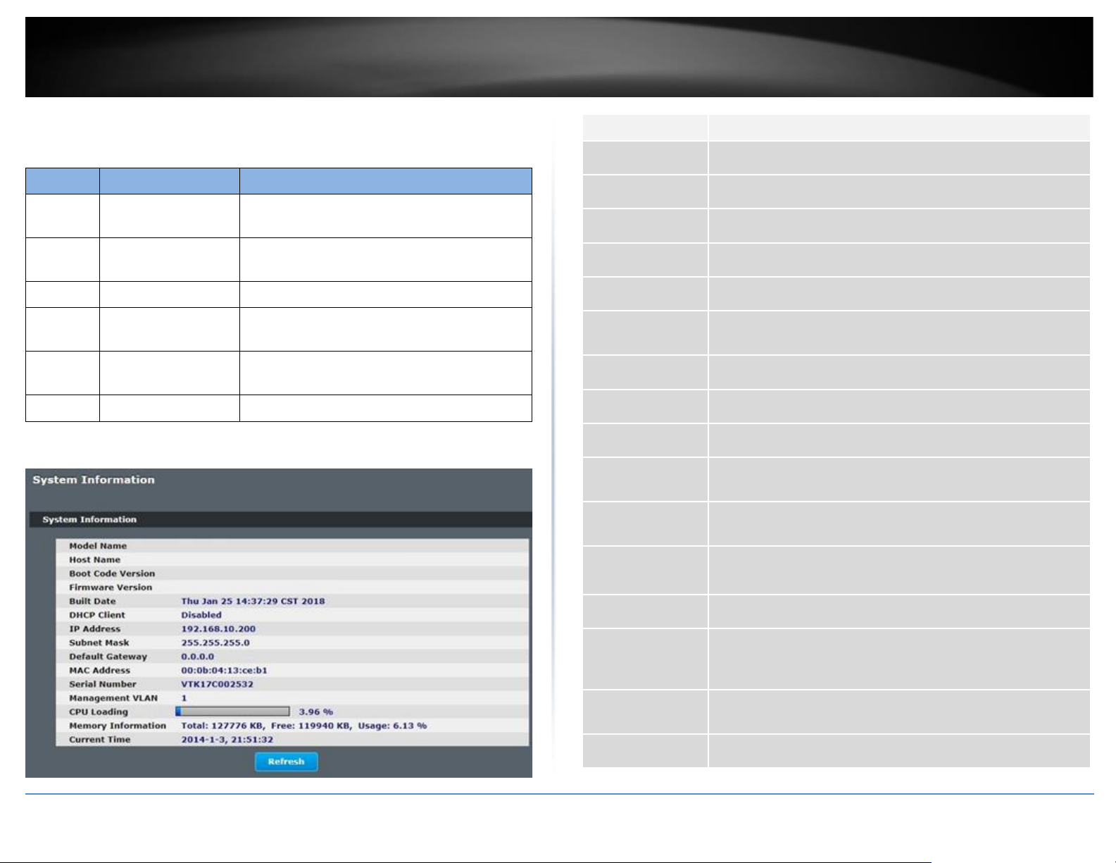
Web Configuration
System Status > System Information
Parameter
Description
Model Name
This field displays the model name of the Switch.
Host Name
This field displays the name of the Switch.
Boot Code Version
This field displays the boot code version.
Firmware Version
This field displays the firmware version.
Built Date
This field displays the built date of the firmware.
DHCP Client
This field displays whether the DHCP client is enabled on the
Switch.
IP Address
This field indicates the IP address of the Switch.
Subnet Mask
This field indicates the subnet mask of the Switch.
Default Gateway
This field indicates the default gateway of the Switch.
MAC Address
This field displays the MAC (Media Access Control) address of the
Switch.
Serial Number
The serial number assigned by manufacture for identification of
the unit.
Management
VLAN
This field displays the VLAN ID that is used for the Switch
management purposes.
CPU Loading
This field displays the percentage of your Switch’s system load.
Memory
Information
This field displays the total memory the Switch has and the
memory which is currently available (Free) and occupied
(Usage).
Current Time
This field displays current date (yyyy-mm-dd) and time
(hh:mm:ss).
Refresh
Click this to update the information in this screen.
 Loading...