

TRENDnet User’s Guide
Cover Page

TRENDnet User’s Guide
Table of Contents
i
Contents
Product Overview ........................................................................... 1
Package Contents .......................................................................................................... 1
Features ......................................................................................................................... 1
Product Hardware Features........................................................................................... 2
Basic Installation & Setup ................................................................ 4
A. Initial Controller Setup .............................................................................................. 4
B. Connect your wireless access points ......................................................................... 6
C. Initial Wireless Setup ................................................................................................. 7
Mounting Installation .................................................................... 10
Create additional users to access controller management ......................................... 20
Set your controller time zone ...................................................................................... 20
Access point management and configuration ................................ 21
Access Point Compatibility .......................................................................................... 21
Manage and configure access points .......................................................................... 21
Discover and add access points ......................................................................... 21
Configuring controller managed access points.................................................. 22
Manually add an access point ........................................................................... 26
Remove access points from the controller ........................................................ 26
Simultaneously upgrade firmware for multiple access points .......................... 27
Upgrade access point firmware using the online upgrade ................................ 27
Moving APs to a new controller ........................................................................ 29
Wireless LAN Controller (TEW-WLC100) ..................................................................... 10
Wireless groups and profiles ....................................................................................... 30
Desktop Hardware Installation .......................................................................... 10
Rack Mount Hardware Installation .................................................................... 10
Wireless PoE Access Point (TEW-755AP / TEW-821DAP) ............................................ 11
Ceiling Mount Installation.................................................................................. 11
Creating a wireless profile ................................................................................. 30
Creating a new wireless group .......................................................................... 33
Assigning access points to a wireless group ...................................................... 33
Captive Portal .............................................................................................................. 35
Wall Mount Installation ..................................................................................... 11
A. To Internal Portal URL ................................................................................... 35
Controller Management ................................................................ 12
Access your wireless controller management page .................................................... 12
Change your controller administrative login password ............................................... 12
B. To Advertisement URL ................................................................................... 38
C. Captive Portal with RADIUS (CoovaChilli) ...................................................... 39
WAP Maps™ ................................................................................................................ 40
Change your controller LAN IP address ....................................................................... 13
Upgrade your controller firmware .............................................................................. 14
View your controller system log .................................................................................. 16
Backup and restore your controller configuration settings ......................................... 16
Reboot your controller ................................................................................................ 18
Set idle timeout for users logged into controller management .................................. 18
Reset your controller to factory defaults .................................................................... 19
Controller default settings ........................................................................................... 19
© Copyright 2017 TRENDnet. All Rights Reserved.
Upload floor plans ............................................................................................. 40
Monitoring access points and clients .......................................................................... 42
Viewing the controller dashboard ..................................................................... 42
View client connections ..................................................................................... 43
Technical Specifications ................................................................ 44
Troubleshooting ........................................................................... 49
Appendix ...................................................................................... 52
TRENDnet User’s Guide
TEW-755AP2KAC / TEW-821DAP2KAC
1
Product Overview
Features
TRENDnet's N300 / AC1200 Dual Band Wireless Controller Kit, TEW-755AP2KAC / TEW821DAP2KAC, is designed to simplify management and setup processes for your access
points. This new controller kit features seamless WiFi roaming, helping your devices stay
connected when transitioning from one access point to another within the network.
Fast BSS Transition, or fast roaming (802.11r), and OKC (opportunistic key caching)
ensures optimal roaming conditions for your mobile WiFi clients. Airtime fairness
provides higher priority to faster WiFi clients without limiting slower WiFi clients.
TRENDnet’s controller kit includes two wireless N300 / AC1200 access points with PoE
injectors, and a wireless controller. This kit allows you to easily setup and manage
access points across your network from a centralized interface. Simultaneously manage
up to 128 access points, perform batch firmware upgrades, and monitor network
connection status.
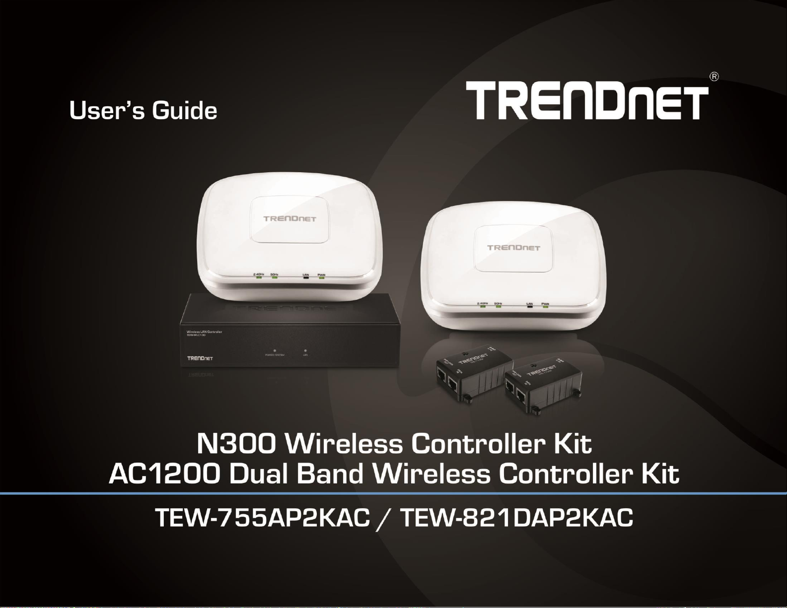
Complete Wireless Controller Kit
This complete controller kit includes two wireless N300 / AC1200 access points with PoE
TEW-755AP2KAC / TEW-821DAP2KAC
Package Contents
The package includes:
1 x TEW-WLC100 wireless LAN controller
2 x TEW-755AP N300 PoE access points or TEW-821DAP AC1200 dual band PoE
access points
2 x TPE-113GI 802.3af Gigabit PoE injectors
2 x Network cables (1.5 m / 5 ft.)
TEW-WLC100 power adapter (12V DC, 1A)
Quick Installation Guide
CD-ROM (User’s Guide)
Controller rack mount kit
Access point mounting plates
If any package contents are missing or damaged, please contact the retail store, online
retailer, or reseller/distributor from which the product was purchased.
injectors and our wireless hardware controller.
Seamless WiFi Roaming
802.11k provides a more efficient WiFi roaming environment by intelligently managing
neighboring APs and passing mobile clients off to the next best access point; 802.11r and
Opportunistic Key Caching (OKC) preauthenticates those WiFi clients with neighboring
APs making for a fast and seamless transition.
Centralized AP Management
Easily manage up to 128 access points across your network. Reduce AP deployment time
by creating group profiles to provision multiple access points simultaneously.
Simultaneously Upgrade Firmware
Select multiple access points to upgrade firmware at the same time
Captive Portal
Create a customized web portal for users to authenticate using unique user names and
passwords. Ideal for hotels, cafes, and businesses that want to provide public WiFi and
manage wireless usage
© Copyright 2017 TRENDnet. All Rights Reserved.
TRENDnet User’s Guide
TEW-755AP2KAC / TEW-821DAP2KAC
2
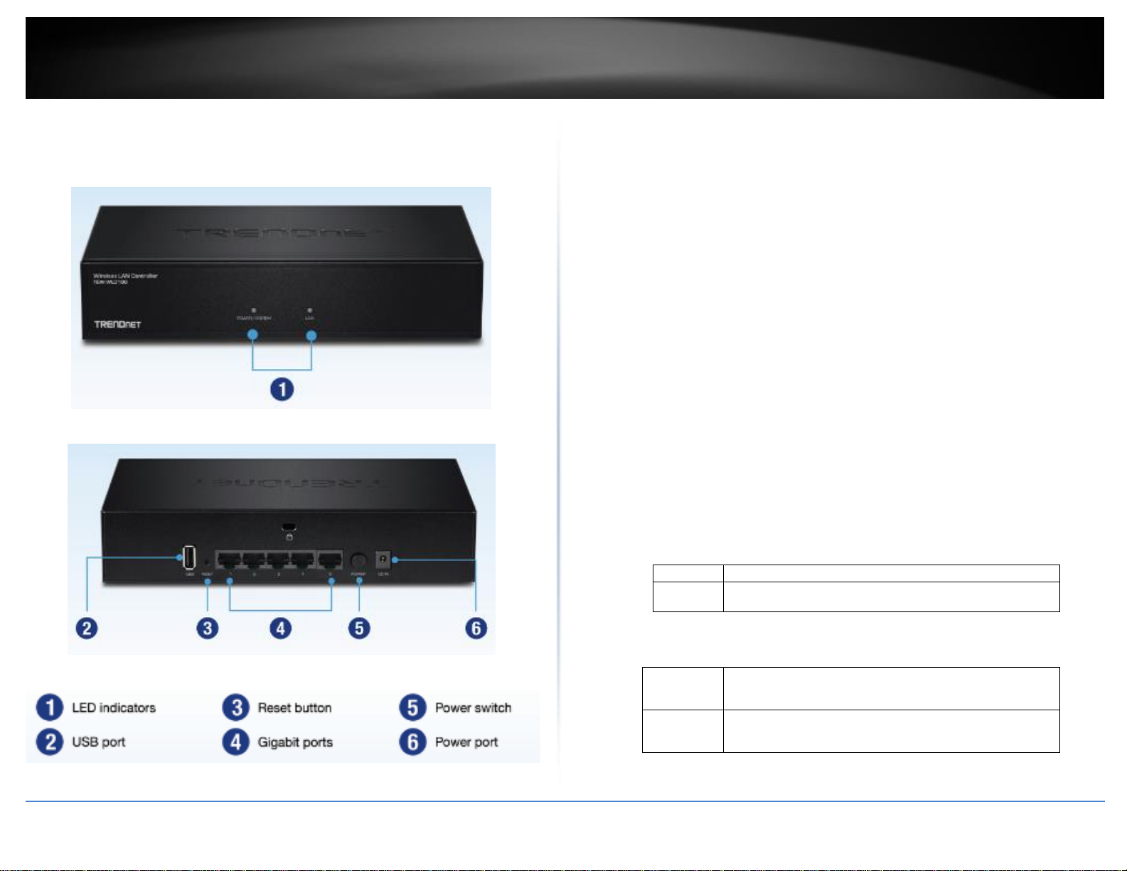
On : When the System LED is on, the device is receiving power.
Off
:
When the System turns off, the power adapter is not
connected or the device is not receiving power.
On (Green)
:
Indicates that a network device (router, switch, access
point, computer, etc.) has been physically connected to
one of the five Gigabit ports (1-5).
Off
:
Indicates no physical Ethernet connection or no network
devices physically connected to any of the Gigabit ports
(1-5).
Product Hardware Features
Wireless LAN Controller (TEW-WLC100)
Front View
Rear View
LED Indicators
Reset Button – Press and hold this button for 15 seconds and release to
reset the controller to factory defaults. The ports LEDs will turn off to
indicate that the reset was initiated.
Gigabit Ports (1-5) – Connect to your LAN network and connect
additional network devices.
Power Port – Connect the included power adapter to your controller
power port and then to an available power outlet.
Note: Use only the adapter that came with your controller.
On/Off Power Switch – Push the controller On/Off push button to turn
your controller “On” (Inner position) or “Off” (Outer position).
USB Port – Backup/restore configuration and upgrade firmware using a
USB storage device.
*Note: Available in controller firmware 2.02 and above. Support for
FAT32/NTFS only.
Security Slot – Can be used to with third party lock to physically secure
your controller to a specific location.
POWER/SYSTEM LED
© Copyright 2017 TRENDnet. All Rights Reserved.
LAN LED
TRENDnet User’s Guide
TEW-755AP2KAC / TEW-821DAP2KAC
3
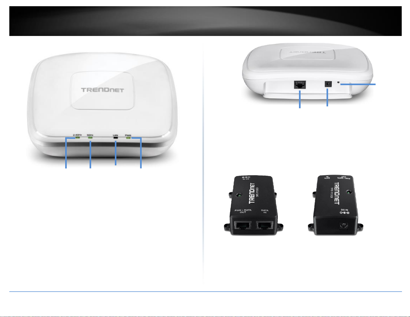
2.4GHz
5GHz
LAN
PWR
Reset
button
Gigabit Port
Power port
N300 / AC1200 PoE Wireless Access Point (TEW-755AP / TEW-821DAP)
2.4GHz: This LED indicator turns green when the wireless is enabled. The LED
indicator blinks during data transmission
5GHz: This LED indicator turns green when the wireless is enabled. The LED
indicator blinks during data transmission (Note: Only available on TEW-821DAP dual
band access point)
LAN: This LED indicator turns green when the access point LAN port is connected.
The LED indicator blinks during data transmission
PWR: This indicator turns green when the device is powered.
Gigabit port: Plug an Ethernet cable (also called network cables) from
your access point to your router and wired network devices.
Power port: Connect the power adapter from your access point power port to
an available power outlet.
Reset button: Use a sharp tool to press and hold this button for 10 seconds to
reset the access point.
Gigabit 802.3af PoE Injector (TPE-113GI)
PWR+DATA OUT – Connects to your PoE access point supplying both power and
data 1000BASE-T via Ethernet cable, standard 802.3af PoE compliant.
DATA IN – Connects your PoE access point to your network (switch or router)
1000BASE-T via Ethernet cable.
DC IN – Connects the 48V DC, 0.5 power adapter to power on the PoE injector and
deliver power to the PoE access point.
© Copyright 2017 TRENDnet. All Rights Reserved.
TRENDnet User’s Guide
TEW-755AP2KAC / TEW-821DAP2KAC
4
Access Point Model
Description
Controller Compatible
Firmware Version
TEW-755AP
N300 PoE Access Point
1.04 or above
TEW-821DAP
AC1200 Dual Band PoE Access Point
1.06 or above
TEW-825DAP
AC1750 Dual Band PoE Access Point
1.02 or above
Basic Installation & Setup
Important Note: Make sure your existing network is using a DHCP server (e.g. router) to
distribute IP addresses to the access points. By default, TRENDnet access points listed
below will obtain an IP address automatically through DHCP or otherwise default back
to 192.168.10.100 / 255.255.255.0 if a DHCP server is not available on your network.
Each access point must be assigned a unique IP address on the same network. The
wireless controller and access points must be connected to the same IP subnet on your
network (e.g. 192.168.10.x / 255.255.255.0).
Access Point Compatibility
By default, the access points included in this kit are controller ready. For any additional
access points, please refer to the access point model compatibility list below and
controller compatible firmware version. You can download the access point’s firmware
from http://www.trendnet.com/support which include instructions on how to upgrade
the firmware.
Before any additional access points are added to the wireless controller, make sure to
reset the access points to factory default after completing the firmware upgrade.
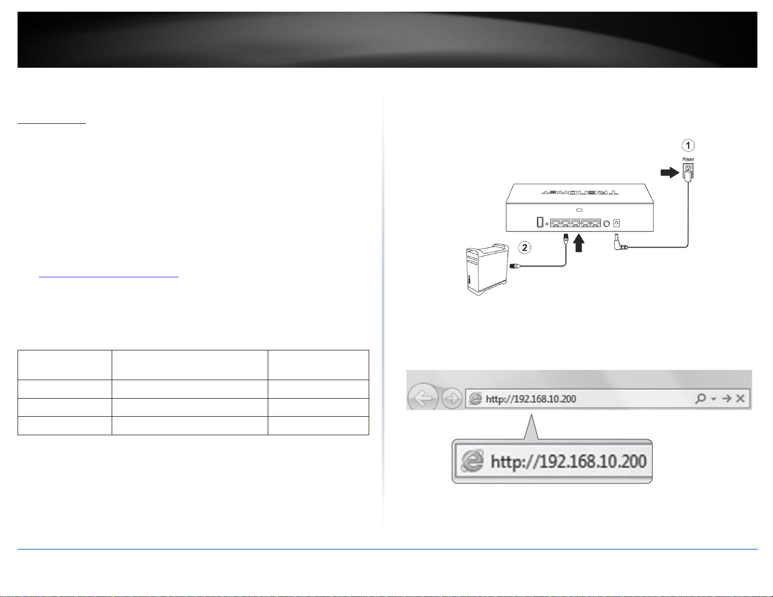
A. Initial Controller Setup
Note: Before connecting the wirele4ss controller to the network and connecting other
devices such as PoE injectors or access points, follow the steps to set up your controller IP
address settings and administrator password first.
3. Assign a static IP address to your computer’s network adapter in the subnet of
192.168.10.x (e.g. 192.168.10.25) and a subnet mask of 255.255.255.0.
4. Open your web browser, and type in the default IP address of the controller in the
address bar, and then press Enter. The default IP address is 192.168.10.200.
© Copyright 2017 TRENDnet. All Rights Reserved.
TRENDnet User’s Guide
TEW-755AP2KAC / TEW-821DAP2KAC
5
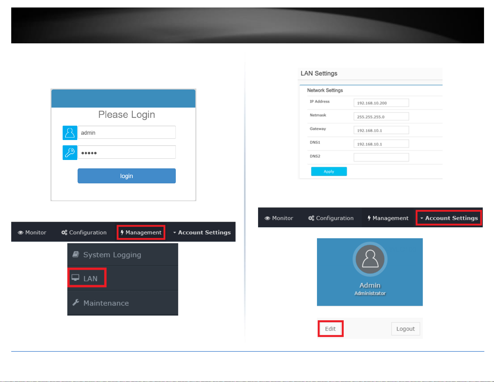
5. Enter the User Name and Password, and then click Login. By default:
User Name: admin
Password: admin
Note: User name and password are case sensitive.
6. Click Management and click on LAN.
7. Configure the controller IP address settings to match the requirements of your
network and click Apply.
8. To change the controller administrator password, click Account Settings and click
Edit.
© Copyright 2017 TRENDnet. All Rights Reserved.

TRENDnet User’s Guide
TEW-755AP2KAC / TEW-821DAP2KAC
6
9. In the New Password and Confirm Password fields, enter the new administrator
password and click OK to save the new password settings. You will be prompted
immediately afterwards to login to the controller management page with the password.
10. Using an Ethernet cable, connect one of the five Gigabit Ethernet ports located on
the back of the wireless controller to your network (e.g. router, switch, etc.)
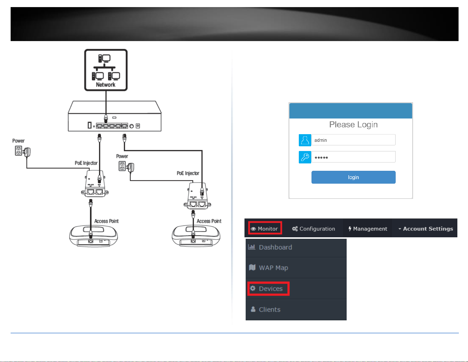
B. Connect your wireless access points
Note: Before mounting the access points to the desired locations, connect the access
points directly to the wireless controller first for initial configuration. The access points
are standard IEEE 802.3af PoE compliant and may also be connect to a PoE/PoE+ switch
for data and power, however, for the purposes of this installation guide we will reference
installation using the supplied PoE injectors.
1. Connect the included Pole injector power adapters (48V DC, 0.5A) to the supplied PoE
injectors DC IN power ports. Connect the adapters to available power outlets to power
on the PoE injectors.
2. Using the included Ethernet cables, connect the wireless controller to the DATA IN
ports of the PoE injectors.
3. Using additional Ethernet cables, connect the access points to the PWR+DATA OUT
ports of the PoE inejctors.
© Copyright 2017 TRENDnet. All Rights Reserved.
TRENDnet User’s Guide
TEW-755AP2KAC / TEW-821DAP2KAC
7
C. Initial Wireless Setup
1. Using your computer and web browser, access the wireless controller management
page using the newly assigned IP address settings (configured in Section A) and login.
Note: If the IP address settings were not changed in Section A, the IP address settings for
the controller are 192.168.10.200 / 255.255.255.0.
2. Click Monitor and click Devices.
© Copyright 2017 TRENDnet. All Rights Reserved.
TRENDnet User’s Guide
TEW-755AP2KAC / TEW-821DAP2KAC
8
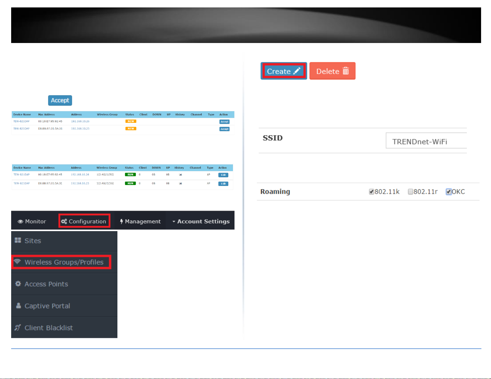
3. The access points will be discovered automatically and appear in the Device List.
Note: If the access points do not appear, make sure access points are powered by
checking the physical LEDs and physical cable connections and refresh the page.
4. After the access points are discovered and appear in the Device List, under the Action
column, click on each access point to add them to the wireless controller.
5. Once the access points have been added to the wireless controller, the Status will
change from NEW to RUN.
6. Click Configuration and click Wireless Groups/Profiles.
7. In the list below, click Create to create a new wireless profile.
8. In the Edit Wireless Group window, enter the wireless network name/SSID for the
wireless network. (e.g. TRENDnet-WiFi)
Note: The SSID is the wireless network name used to broadcast and be discovered by
your wireless client devices to connect to your wireless network.
9. For Roaming options, select 802.11k and OKC wireless roaming protocols to ensure
fast transition wireless connectivity for client devices when roaming between multiple
access points.
© Copyright 2017 TRENDnet. All Rights Reserved.
TRENDnet User’s Guide
TEW-755AP2KAC / TEW-821DAP2KAC
9
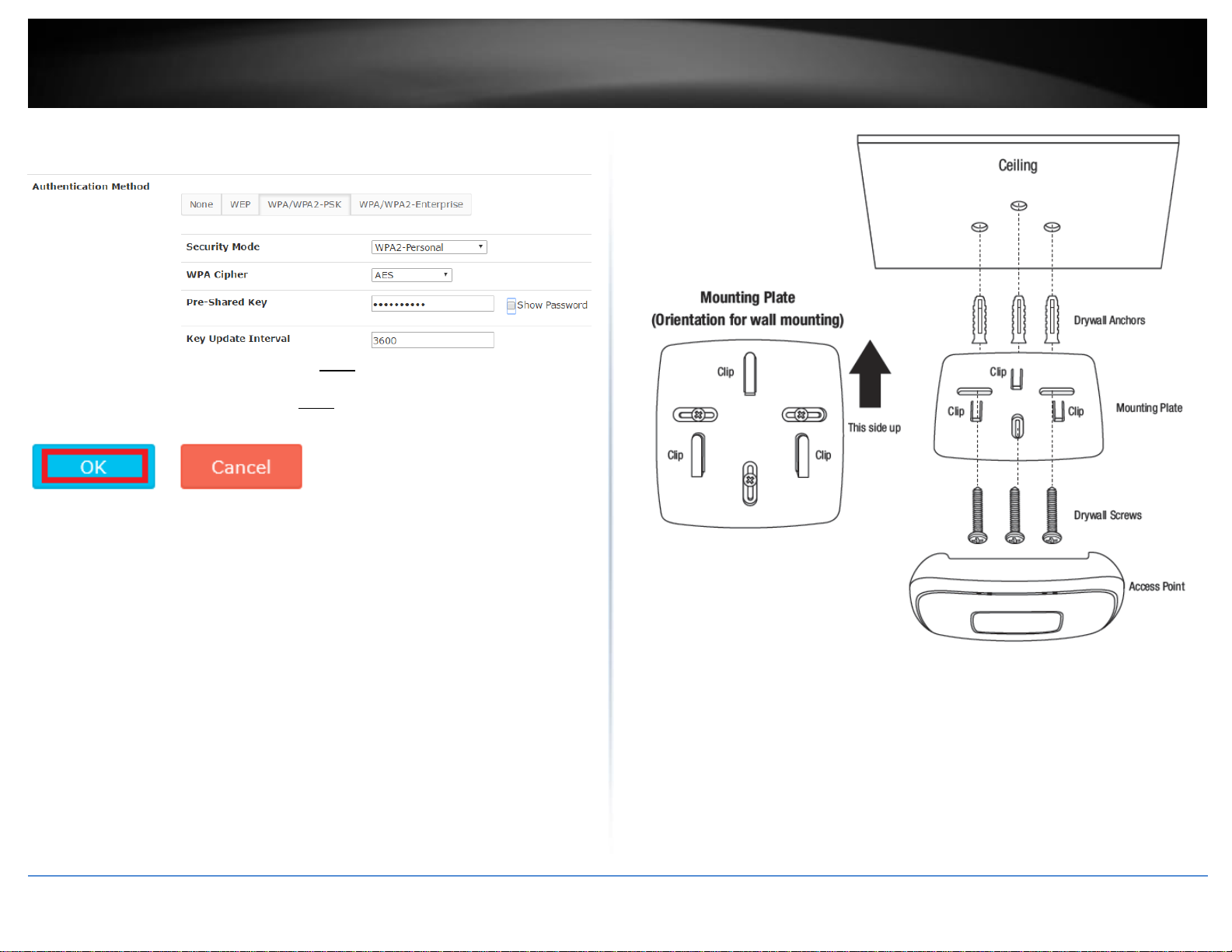
10. For Authentication method, select WPA/WPA2-PSK. For the Security Mode, select
WPA2-Personal. For the WPA Cipher, select AES and enter the Pre-Shared Key required
to connect to your wireless network. Click OK.Note: The pre-shared key is the
key/password (8-63 alphanumeric characters) client devices will be required to enter in
order to connect to your wireless network.Note: It may take up to 1 minute for
configuration settings to be applied to the access points
11. The initial wireless settings are complete. You can use the included hardware to
mount the access points in the desired locations.
Note: The access points must be connected to the same IP subnet as your wireless
controller. (e.g. 192.168.10.x / 255.255.255.0)
12. To mount the access points, install the mounting plates first to the desired wall or
ceiling using the included drywall anchors and screws. Install the mounting plates with
the clips facing away from the wall. If wall mounting, install the mounting plates with
the correct orientation. After the mounting plates are properly installed, align the access
point mounting holes with the mounting plate clips and slide in access point to lock into
place.
© Copyright 2017 TRENDnet. All Rights Reserved.

TRENDnet User’s Guide
TEW-755AP2KAC / TEW-821DAP2KAC
10
Mounting Installation
Wireless LAN Controller (TEW-WLC100)
Desktop Hardware Installation
The site where you install the hub stack may greatly affect its performance. When
installing, consider the following pointers:
Note: The controller model may be different than the one shown in the example
illustrations.
Install the controller in a fairly cool and dry place.
Install the Controller in a site free from strong electromagnetic field generators
(such as motors), vibration, dust, and direct exposure to sunlight.
Leave at least 10cm of space at the front and rear of the hub for ventilation.
Install the controller on a sturdy, level surface that can support its weight, or in
an EIA standard-size equipment rack. For information on rack installation, see
the next section, Rack Mounting.
When installing the Controller on a level surface, attach the rubber feet to the
bottom of each device. The rubber feet cushion the hub and protect the hub
case from scratching.
Rack Mount Hardware Installation
The controller can be mounted in an EIA standard-size, 19-inch rack, which can be
placed in a wiring closet with other equipment. Attach the mounting brackets at the
controller’s front panel (one on each side), and secure them with the provided screws.
Note: The controller model may be different than the one shown in the example
illustrations.
Then, use screws provided with the equipment rack to mount each controller in the
rack.
© Copyright 2017 TRENDnet. All Rights Reserved.
TRENDnet User’s Guide
TEW-755AP2KAC / TEW-821DAP2KAC
11
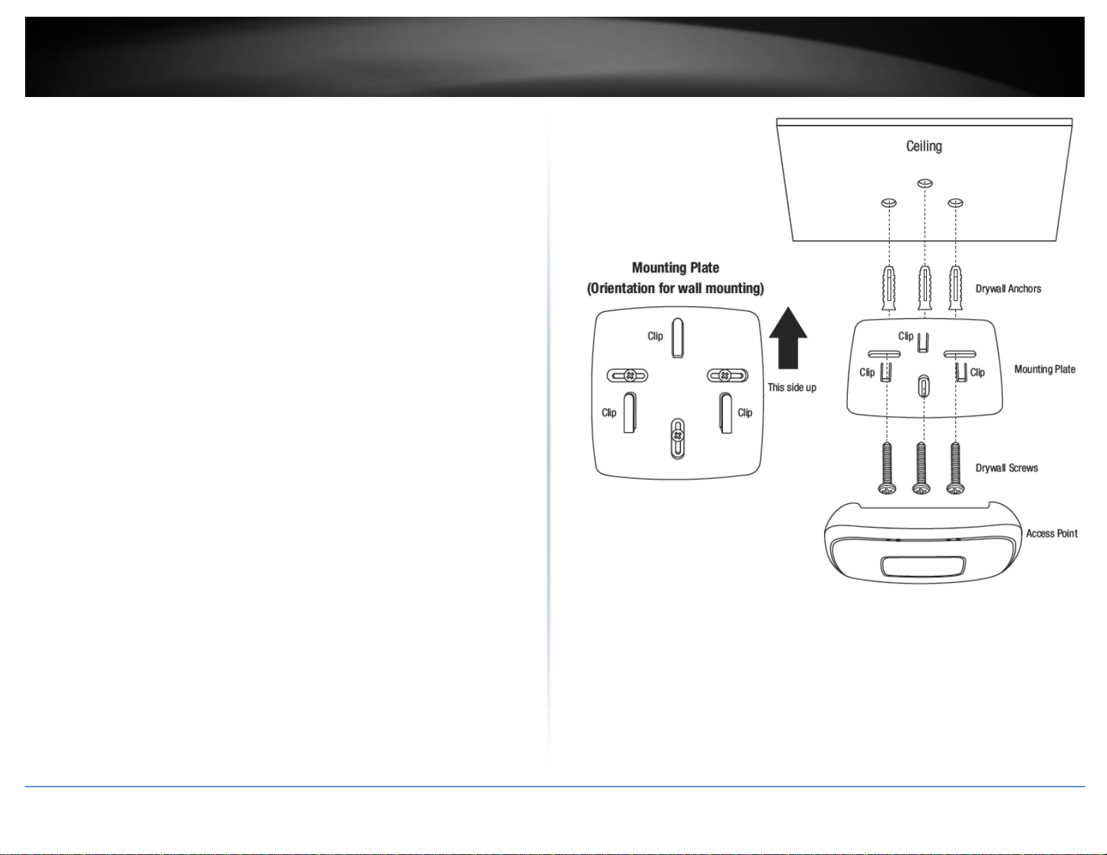
Wireless PoE Access Point (TEW-755AP / TEW-821DAP)
Ceiling Mount Installation
Select the desired ceiling to mount the access point.
First, install the mounting plate using the included drywall anchors (only
required if in wall stud installation points are not available) and screws.
Note: It’s optional to use a stud finder to locate in wall studs and mark as
installation points but not required.
Place mounting plate on ceiling (clips facing away from ceiling) in desired
mounting location and mark the points where the anchors/screws will be
installed.
Using a power drill and drill bits, create the holes were the anchors/screws will
be installed.
If anchors are required, install the anchors in the holes created first, then
attached the mounting plate with the drywall screws using the power drill and
Phillips bit or screwdriver.
After mounting plates are installed, align the access point mounting holes with
the mounting plate clips and slide in acces point to lock into place.
Wall Mount Installation
Select the desired wall to mount the access point and make sure to install the
mounting plates with the correct orientation.
First, install the mounting plate using the included drywall anchors (only
required if in wall stud installation points are not available) and screws.
Note: It’s optional to use a stud finder to locate in wall studs and mark as
installation points but not required.
Place mounting plate on wall (clips facing away from wall) in desired mounting
location and mark the points where the anchors/screws will be installed.
Using a power drill and drill bits, create the holes were the anchors/screws will
be installed.
If anchors are required, install the anchors in the holes created first, then
attached the mounting plate with the drywall screws using the power drill and
Phillips bit or screwdriver.
After mounting plates are installed, align the access point mounting holes with
the mounting plate clips and slide in acces point to lock into place.
© Copyright 2017 TRENDnet. All Rights Reserved.

TRENDnet User’s Guide
TEW-755AP2KAC / TEW-821DAP2KAC
12
Controller Management
Access your wireless controller management page
Note: Your controller default management IP address http://192.168.10.200 is accessed
through the use of your Internet web browser (e.g. Internet Explorer®, Firefox®,
Chrome™, Safari®, Opera™) and will be referenced frequently in this User’s Guide.
1. Open your web browser and go to the IP address http://192.168.10.200. Your
controller will prompt you for a user name and password.
2. Enter the user name and password. By default:
User Name: admin
Password: admin
Note: User Name and Password are case sensitive.
Change your controller administrative login password
Account Settings
1. Log into your controller management page (see “Access you wireless controller
management page” on page 12).
2. Click on Account Settings and click on Edit.
3. In the New Password and Confirm Password fields, enter the new password and click
OK. You will be prompted immediately to log back into the controller management page
with the new password. Note: The password can be up to 32 alphanumeric characters.
© Copyright 2017 TRENDnet. All Rights Reserved.
Note: If you change the controller login password, you will need to access the controller
management page using the User Name “admin” and the new password.
TRENDnet User’s Guide
TEW-755AP2KAC / TEW-821DAP2KAC
13
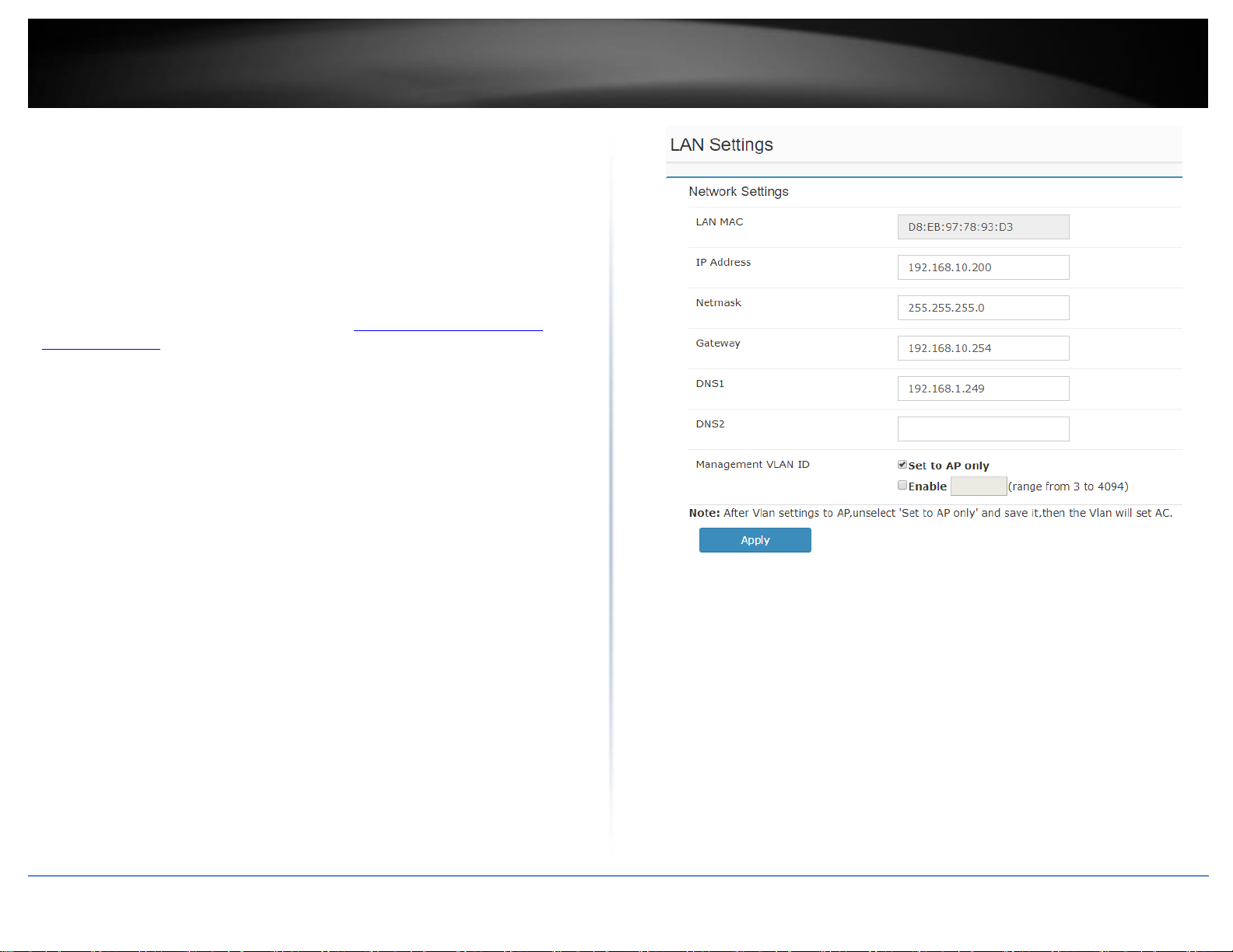
Change your controller LAN IP address
Management > LAN
This section allows you to change your controller LAN IP address settings. Typically, the
IP address settings should be changed to match your existing network subnet in order to
access the switch management page on your network.
Default Controller IP Address: 192.168.10.200
Default Controller IP Subnet Mask: 255.255.255.0
1. Log into your controller management page (see “Access you wireless controller
management page” on page 12).
2. Click on Management and click on LAN.
3. Review the settings. When you have completed making changes, click Apply to save
the settings.
LAN MAC: Displays the controller LAN MAC address. (This parameter cannot be
changed).
IP Address: Enter the new controller IP address. (e.g. 192.168.200.200)
Netmask: Enter the new controller subnet mask. (e.g. 255.255.255.0)
Gateway: Enter the default gateway IP address. (e.g. 192.168.200.1 or typically
your router/gateway to the Internet).
DNS1/DNS2: Enter the primary and secondary DNS servers IP address in order to
resolve domain or host names. (e.g. 192.168.200.20)
Management VLAN ID: By default, the management VLAN ID assigned to the
access points and controller is VLAN ID 1. To change the management VLAN ID of
the access points only, leave “Set to AP only” checked and check “Enable”, then
enter the new management VLAN ID to assign. To change both the controller and
access points management VLAN ID, uncheck “Set to AP only” and check
“Enable”, then enter the new management VLAN ID to assign.
Note: The gateway and DNS IP addresses must be assigned to the correct Internet
gateway/router and DNS name resolution server address in order for the controller to
check for available online firmware updates.
© Copyright 2017 TRENDnet. All Rights Reserved.
TRENDnet User’s Guide
TEW-755AP2KAC / TEW-821DAP2KAC
14
Upgrade your controller firmware
Management > Maintenance
TRENDnet may periodically release firmware upgrades that may add features or fix
problems associated with your TRENDnet controller model and version. To check if
there is a firmware upgrade available for your device, please check your TRENDnet
model and version using the link. http://www.trendnet.com/support.
In addition, it is also important to verify if the latest firmware version is newer than the
one your controller is currently running. To identify the firmware that is currently
loaded on your controller, log in to the controller, click on the Administrator section and
then on the Status. The firmware used by the controller is listed at the top of this page.
If there is a newer version available, also review the release notes to check if there were
any new features you may want or if any problems were fixed that you may have been
experiencing.
Important Note: If your current firmware version is 2.00, you will need to upgrade to
firmware version 2.01 before upgrading to version 2.02 or above.
Please note the following:
Do not interrupt the firmware upgrade process. Do not turn off the device or
push the reset button during the firmware upgrade.
If you are upgrading the firmware using a laptop computer, ensure that the
laptop is connected to a power source or ensure that the battery is fully
charged.
Disable sleep mode on your computer as this may interrupt the firmware
upgrade process.
Do not upgrade the firmware using a wireless connection, only use a wired
network connection.
Any interruptions during the firmware upgrade process may permanently
damage your controller.
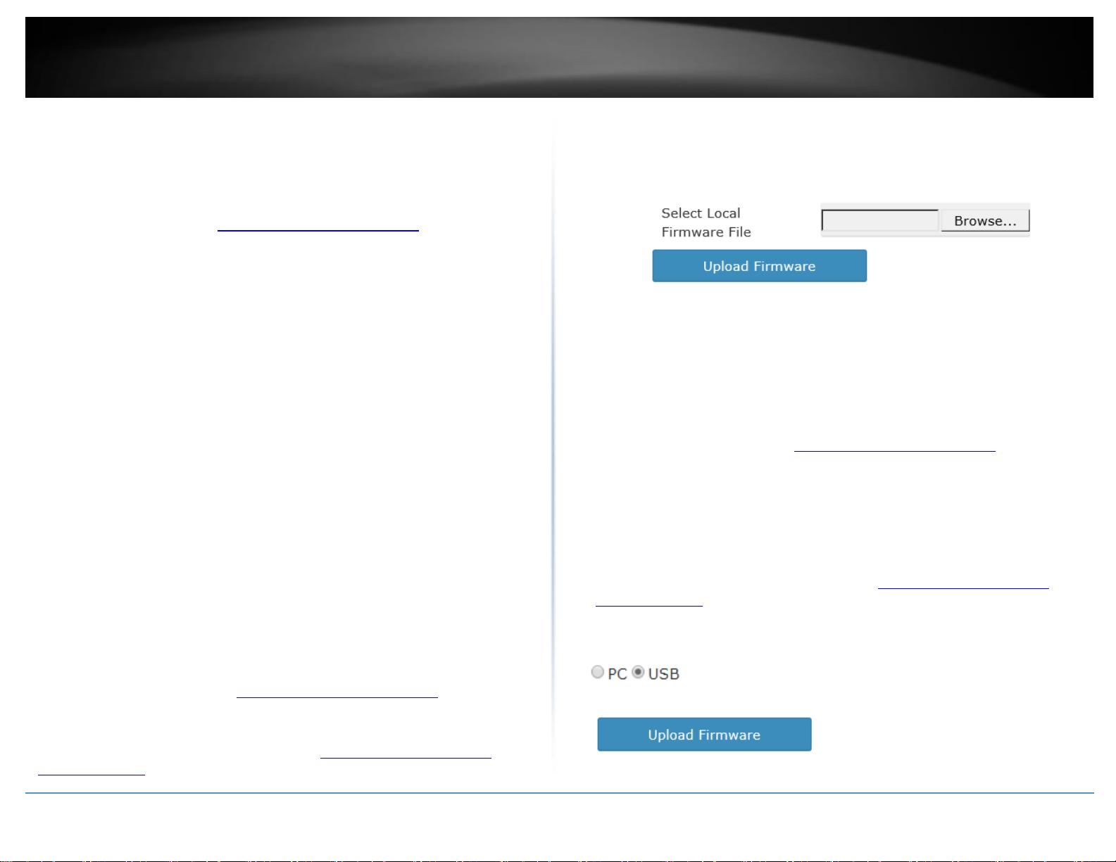
Upgrade firmware from computer hard drive
1. If a firmware upgrade is available (http://www.trendnet.com/support), download the
firmware to your computer.
2. Unzip the file to a folder on your computer.
3. Log into your controller management page (see “Access you wireless controller
management page” on page 10).
4. Click on Management and click on Maintenance.
5. Depending on your web browser, in the Firmware Management section, click Browse
or Choose File.
6. Navigate to the folder on your computer where the unzipped firmware file (.img) is
located and select it.
7. Click Upload Firmware. If prompted, click Yes or OK.
8. Wait for the controller to complete the firmware.
Upgrade firmware from USB storage device
1. If a firmware upgrade is available (http://www.trendnet.com/support), download the
firmware to your computer.
2. Unzip the file to a folder on your computer.
3. Rename the firmware file (Default: TEW-WLC100-XXXX-FW.img) to upload.tar.gz. and
save the file to the USB storage device. (FAT32 format only)
4. Plug in the USB storage device (FAT32 format only) into the USB port located on the
back of the controller.
5. Log into your controller management page (see “Access you wireless controller
management page” on page 10).
6. Click on Management and click on Maintenance.
5. Select USB.
7. Click Upload Firmware. If prompted, click Yes or OK.
8. Wait for the controller to complete the firmware.
© Copyright 2017 TRENDnet. All Rights Reserved.
TRENDnet User’s Guide
TEW-755AP2KAC / TEW-821DAP2KAC
15
Upgrade firmware using the online upgrade
The controller management page will display a notification if the new firmware upgrade
is available and provide you with the option to upgrade the firmware via online through
the controller management page.
*Note: Available in controller firmware 2.02 and above.
1. Log into your controller management page (see “Access you wireless controller
management page” on page 10).
2. Click on Management and click on Maintenance.
3. If new firmware is available online, a notification will appear next to the current
firmware version.
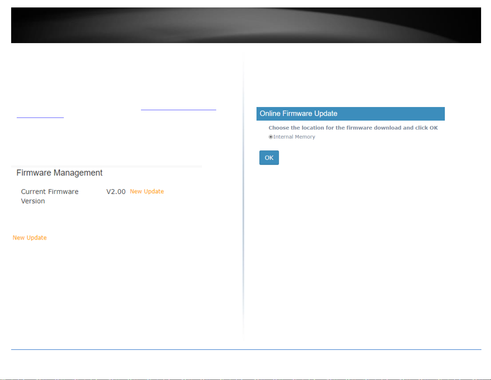
4. Click the “New Update” notification.
5. In the Online Firmware Update prompt, click OK to start the online firmware upgrade
process. Please wait for the firmware upgrade process to complete.
Note: By default, the Internal Memory settings is selected to temporarily download the
firmware files to the controller’s internal memory for the firmware upgrade process. If a
USB storage device is plugged into the controller’s USB port, the external storage device
will appear as an available storage location to download the firmware files for the
firmware upgrade process.
Please note the following:
Do not interrupt the firmware upgrade process. Do not turn off the device or
push the reset button during the firmware upgrade. Rebooting or resetting
during the firmware upgrade process may permanently damage your
controller.
6. During the online upgrade, messages will be displayed next to the current firmware
version to indicate the firmware upgrade status. After the firmware upgrade has
completed successfully, the new firmware version will be displayed.
Downloading – Indicates that the new firmware files are currently being
downloaded to the selected storage location.
Updating - Indicates that the device is currently being updated to the new
firmware.
Completed – Indicates that the firmware upgrade has completed
successfully.
Failed – Indicates that the firmware upgrade process failed.
Note: You can try the online firmware upgrade again or manually download the
firmware file from the TRENDnet website and upgrade the firmware manually.
© Copyright 2017 TRENDnet. All Rights Reserved.
TRENDnet User’s Guide
TEW-755AP2KAC / TEW-821DAP2KAC
16
View your controller system log
Management > System Logging
Your controller system log can be used to obtain activity information on the
functionality of your controller or for troubleshooting purposes.
1. Log into your controller management page (see “Access you wireless controller
management page” on page 12).
2. Click on Management and click on System Logging.
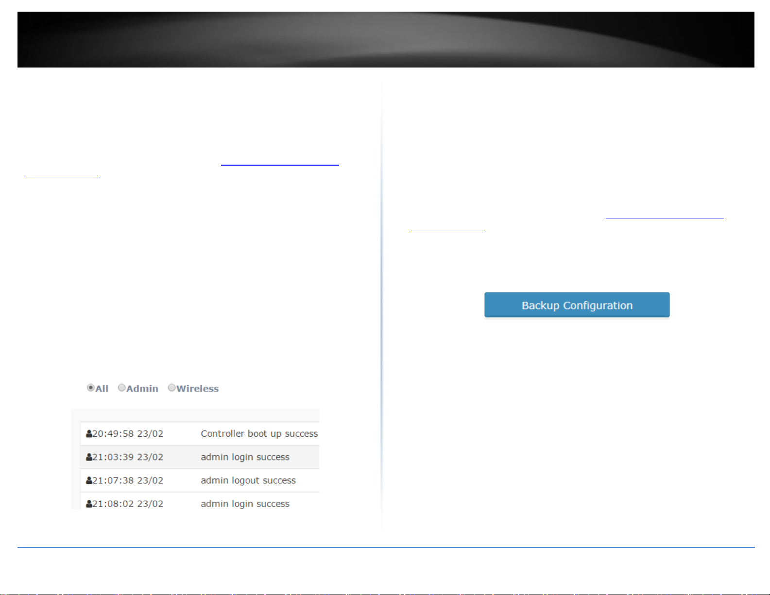
3. To filter which logging you would like to view, you can select from one of the
following options.
All – Displays all logging.
Admin – Displays only successful or failed controller logins or logouts to the
controller management interface.
Wireless – Displays only information about access point and wireless client
connections.
Time Limit - You can select the time interval (Time Limit of the most recent
logging to display from the current time (0-30 min, 30-60 min, or 1-2 hrs prior to
the current time). You can also
Search – Allows you to enter a custom filter/keyword to search in system logging,
for example AP or client MAC address, etc.
Backup and restore your controller configuration settings
Management > Maintenance
You may have added many customized settings to your controller and in the case that
you need to reset your controller to default, all your customized settings would be lost
and would require you to manually reconfigure all of your controller settings instead of
simply restoring from a backed up controller configuration file.
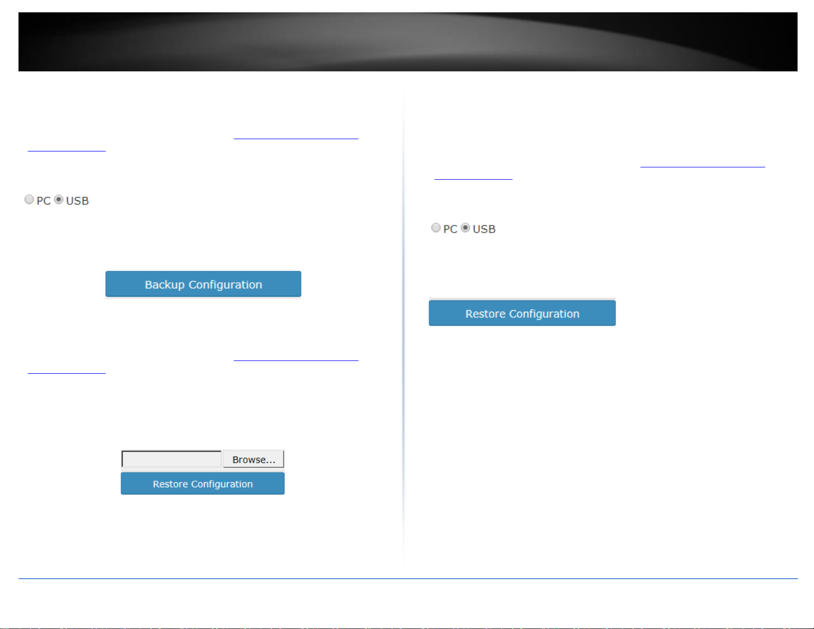
To backup your controller configuration:
Backup configuration to file on computer hard drive
1. Log into your controller management page (see “Access you wireless controller
management page” on page 12).
2. Click on Management and click on Maintenance.
3. Next to Encrypt Key, enter a custom encryption key (8 alphanumeric characters max.)
to use for the backup configuration file and click Apply.
4. Click Backup Configuration.
5. Depending on your web browser settings, you may be prompted to save a file (specify
the location) or the file may be downloaded automatically to the web browser
settings default download folder. (Default Filename: backup_cfg_WLC100.cfg)
© Copyright 2017 TRENDnet. All Rights Reserved.
TRENDnet User’s Guide
TEW-755AP2KAC / TEW-821DAP2KAC
17
Backup configuration to file on USB storage (FAT32 supported only)
1. Plug in a USB storage device (FAT32 format only) into the USB port located on the
back of the controller.
2. Log into your controller management page (see “Access you wireless controller
management page” on page 12).
3. Click on Management and click on Maintenance.
4. Select USB.
5. Next to Encrypt Key, enter a custom encryption key (8 alphanumeric characters max.)
to use for the backup configuration file and click Apply.
6 Click Backup Configuration. The file will be backed up to your USB storage device
(Default Filename: cfg.tar.gz)
To restore your controller configuration:
Restore configuration from file on computer hard drive
1. Log into your controller management page (see “Access you wireless controller
management page” on page 12).
3. Click on Management and click on Maintenance.
4. Next to Encrypt Key, make sure the encryption key is the same key assigned when the
backup configuration file was created. If not, enter the correct encryption key (8
alphanumeric characters max.) assigned to the backup configuration file and click Apply.
5. Click Browse.
Restore configuration from file on USB storage device (FAT32 supported only)
1. Rename the backup configuration file (Default Filename: backup_cfg_WLC100.cfg) to
cfg.tar.gz and save the file to the USB storage device. (FAT32 format only)
2. Plug in the USB storage device (FAT32 format only) into the USB port located on the
back of the controller.
3. Log into your controller management page (see “Access you wireless controller
management page” on page 12).
4. Click on Management and click on Maintenance.
5. Select USB.
6. Next to Encrypt Key, make sure the encryption key is the same key assigned when the
backup configuration file was created. If not, enter the correct encryption key (8
alphanumeric characters max.) assigned to the backup configuration file and click Apply
7. Click Restore Configuration. If prompted, click Yes or OK.
8. Wait for the controller to restore settings.
6. A separate file navigation window should open.
7. Select the controller configuration file to restore and click Restore Configuration.
(Default Filename: backup_cfg_WLC100.cfg). If prompted, click Yes or OK.
8. Wait for the controller to restore settings.
© Copyright 2017 TRENDnet. All Rights Reserved.

TRENDnet User’s Guide
TEW-755AP2KAC / TEW-821DAP2KAC
18
Reboot your controller
Management > Maintenance
You may want to restart your controller if you are encountering difficulties with your
controller and have attempted all other troubleshooting.
There are two methods that can be used to restart your controller.
Turn the controller off for 10 seconds using the controller On/Off switch located
on the rear panel of your controller or disconnecting the power port, see
“Product Hardware Features” on page 2.
Use this method if you are encountering difficulties with accessing your controller
management page. This is also known as a hard reboot or power cycle.
OR
Controller Management Page – This is also known as a soft reboot or restart and
steps are shown below.
1. Log into your controller management page (see “Access you wireless controller
management page” on page 12).
2. Click on Management and click on Maintenance.
3. In the Backup/Restore System Configuration section, click Reboot Controller.
Set idle timeout for users logged into controller management
Management > Maintenance
You can set the amount of idle time before automatic log out when a user is logged into
the controller management page.
1. Log into your controller management page (see “Access you wireless controller
management page” on page 12).
2. Click on Management and click on Maintenance.
3. In the field, enter the amount of time in seconds (120-3600) to specify the amount of
idle time before a user is automatically logged out of the controller management page
and click Apply.
4. Wait for the device to reboot.
© Copyright 2017 TRENDnet. All Rights Reserved.

TRENDnet User’s Guide
TEW-755AP2KAC / TEW-821DAP2KAC
19
Administrator User Name
admin
Administrator Password
admin
Controller IP Address
192.168.10.200
Controller Subnet Mask
255.255.255.0
Controller Default Gateway
192.168.10.1
Primary DNS Server
192.168.10.1
Reset your controller to factory defaults
Management > Maintenance
You may want to reset your controller to factory defaults if you are encountering
difficulties with your controller and have attempted all other troubleshooting. Before
you reset your controller to defaults, if possible, you should backup your controller
configuration first, see “Backup and restore your controller configuration settings” on
page 15.
There are two methods that can be used to reset your controller to factory defaults.
Reset Button – Located on the rear panel of your controller, see “Product
Hardware Features” on page 2. Use this method if you are encountering
difficulties with accessing your controller management page.
OR
Controller Management Page
1. Log into your controller management page (see “Access you wireless controller
management page” on page 12).
2. Click on Management and click on Maintenance.
3. In the Backup/Restore System Configuration section, click Restore to factory default.
Controller default settings
© Copyright 2017 TRENDnet. All Rights Reserved.

TRENDnet User’s Guide
TEW-755AP2KAC / TEW-821DAP2KAC
20
Create additional users to access controller management
Management > User
You may want to create additional administrative accounts or user accounts with read
only privileges to the controller management configuration.
1. Log into your controller management page (see “Access you wireless controller
management page” on page 12).
2. Click on Management and click on User.
3. To create a new user, click Create.
Set your controller time zone
Configuration > Sites
1. Log into your controller management page (see “Access you wireless controller
management page” on page 12).
2. Click on Configuration and click on Sites.
3. Click the Time Zone drop down list and select the correct time zone. Click OK.
4. Enter the user name and password for the new account.
5. Select the permission settings for the new user account and click OK to create the
new account.
admin – administrative users can access controller management and modify controller
configuration settings. Full access.
normal – restricted users can access controller management and view configuration but
cannot modify any controller configuration settings. Restricted access.
© Copyright 2017 TRENDnet. All Rights Reserved.

TRENDnet User’s Guide
TEW-755AP2KAC / TEW-821DAP2KAC
21
Access Point Model
Description
Controller Compatible
Firmware Version
TEW-755AP
N300 PoE Access Point
1.04 or above
TEW-821DAP
AC1200 Dual Band PoE Access Point
1.06 or above
TEW-825DAP
AC1750 Dual Band PoE Access Point
1.02 or above
Access point management and configuration
Important Note: Make sure your existing network is using a DHCP server to distribute IP
addresses to the access points. By default, TRENDnet access points listed below will
obtain an IP address automatically through DHCP or otherwise default back to
192.168.10.100 / 255.255.255.0 if a DHCP server is not available on your network. Each
access point must be assigned a unique IP address on the same network. The wireless
controller and access points must be connected to the same IP subnet on your network.
(e.g. 192.168.10.x / 255.255.255.0)
Access Point Compatibility
By default, the access points included in this kit are controller ready. For any additional
access points, please refer to the access point model compatibility list below and
controller compatible firmware version. You can download the access point’s firmware
from http://www.trendnet.com/support which include instructions on how to upgrade
the firmware.
Before any additional access points are added to the wireless controller, make sure to
reset the access points to factory default.
Manage and configure access points
This section describes how to discover new controller compatible APs (access points)
and how to add/remove them to the wireless LAN controller.
Note: Once APs are added to the controller, they must be managed and configured
through the controller and can no longer be managed individually. APs must be
removed/disconnected from the controller or reset to default in order to regain
individual AP management access. Although APs individually offer multiple modes, the
controller is only intended to manage the APs when used in access point mode.
Discover and add access points
Monitor > Devices
1. Log into your controller management page (see “Access you wireless controller
management page” on page 12).
2. Click on Monitor and click Devices and newly connected APs will automatically
appear in the Device List. Note: If your AP does not appear in the list, make sure to
double check all of the AP physically connections and refresh the discovery page.
3. The Device List displays the following information about each AP.
Device Name – Displays the AP device name. Clicking the Device Name will
display a summarized list of information about the AP.
o Locate – If the AP has been marked on a previously uploaded WAP
Map floorplan, clicking this link will open the WAP Map floorplan.
o Reboot – Clicking this link will reboot the AP.
Mac Address – Displays the AP MAC address.
Address – Displays the AP IP address. Clicking the IP address will open the AP
web management page in a web browser tab or window.
Wireless Group – Displays the AP wireless group assignment for each band.
Example: 1(2.4G)/1(5G) means both 2.4G and 5G bands are assigned to
wireless group 1. 2(2.4G)/1(5G) means 2.4G band is assigned to wireless group
2 and 5G band is assigned to wireless group 1.
Status – Displays the current AP status.
© Copyright 2017 TRENDnet. All Rights Reserved.

TRENDnet User’s Guide
TEW-755AP2KAC / TEW-821DAP2KAC
22
o NEW - The AP has not been added to any other wireless
controllers and is available to add to the currently managed controller.
o RUN - The AP has been successfully added to the currently
managed wireless controller. When APs are added to the controller,
they can no longer be managed individually, only managed through
the controller. APs will need to be removed from the controller in
order to be individually managed.
o OFF - The AP has been added to the currently managed wireless
controller but AP is offline.
o LOCK - The AP has been added to another wireless controller
and is not available to add to the currently managed controller. When
APs are added to the controller, they can no longer be managed
individually, only managed through the controller they have been
added. APs will need to be removed from the controller in order to be
individually managed.
Client – Displays the current number of connected client devices to the AP.
Download – Displays the current total of data downloaded (received) by the AP
in bytes (B).
Upload - Displays the current total amount of data uploaded (transmitted) by
the AP in bytes (B).
History – Displays a brief snapshot of the total amount of data downloaded
(received) by the AP over the last 5 minutes in graph form.
o Locate – If the AP has been marked on a previously uploaded WAP
Map floorplan, clicking this link will open the WAP Map floorplan.
o Reboot – Clicking this link will reboot the AP.
Channel – Displays the current wireless channels the AP is operating on each
band.
Example: 1(ng),161(ac) means 2.4G band is operating on channel 1 and 5G
band is operating on channel 161. First number = 2.4G channel, Second number
= 5G channel.
Type – Displays the device type. AP means Access Point.
Action – Displays an available action for the AP if it is available to add or
managed by the current wireless controller.
Configuring controller managed access points
Configuration > Access Points
1. Log into your controller management page (see “Access you wireless controller
management page” on page 12).
2. Click on Configuration and click Access Points and the list will display all of the APs
that have already been added to the wireless controller. The list displays the following
information about each AP.
MAC Address – Displays the AP MAC address.
Device Name – Displays the AP device name.
Firmware Version – Displays the current AP firmware version.
Description – Displays the AP description
Channel – Displays the current operating 2.4G and 5G channels.
o – Click this action to add the AP to the wireless LAN
controller. After adding APs, the AP status will change to RUN when
successfully added to the controller.
Note: When APs are added to the controller, they can no longer be
managed individually, only managed through the controller. APs will
need to be removed from the controller in order to be individually
managed.
o – If AP is already added, click this action to configure the AP
settings.
Example: 1 / 161 means the 2.4G band is operating on channel 1 and 5G
channel is operating on channel 161. First number = 2.4G channel, Second
number = 5G channel.
© Copyright 2017 TRENDnet. All Rights Reserved.

TRENDnet User’s Guide
TEW-755AP2KAC / TEW-821DAP2KAC
23
Note: When APs are added to the controller for the first time, the default 2.4G
channel is set to 1 and default 5G channel is set 161 (North America) & 48
(Europe). It is recommended for APs in the same wireless group to use the same
channel for seamless roaming.
Tx Power – Displays the 2.4G and 5G transmit power setting.
Example: auto / auto means 2.4G transmit power is set to auto and 5G transmit
power is set to auto. (First: 2.4G setting / Second: 5G setting)
Action – Click to modify the AP individual settings.
Note: It is recommended that APs that are in the same wireless group are
always configured with the same individual settings to produce optimum
wireless connectivity and performance. By default, when APs are first added to
the wireless controller, all APs are set to use the same default settings including
specific 2.4G channel 1.
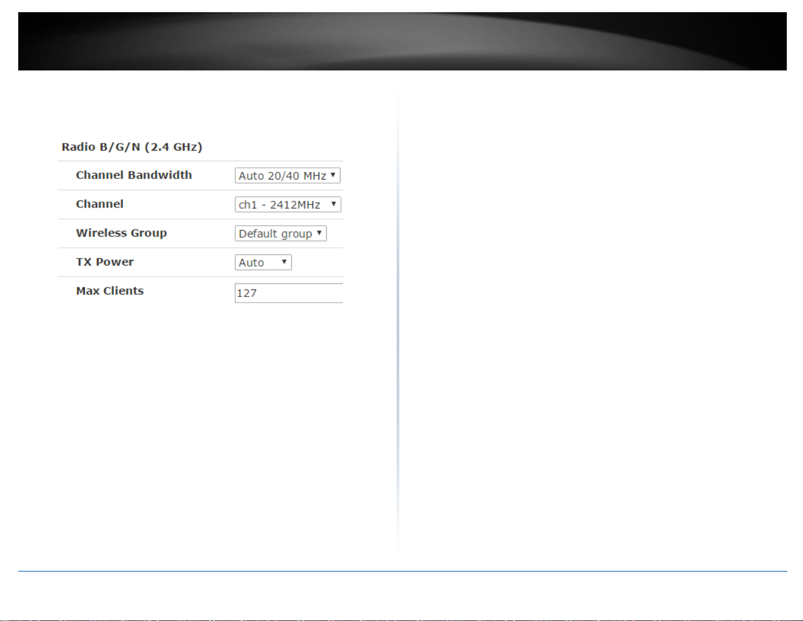
o Channel Bandwidth – Set the 2.4G channel bandwidth setting for the
AP.
20 MHz – This mode operates using a single 20MHz channel
for wireless devices connecting at 2.4G 802.11b/g/n. This
setting may provide more stability than Auto 20/40 MHz for
connectivity in busy wireless environments where there are
several neighboring wireless networks in the area.
Under , you can modify the AP individual settings. Click OK to save the
changes.
AP Model – Displays the AP model. Note: This setting cannot be modified.
MAC Address – Displays the AP MAC address. Note: This setting cannot be
modified.
Device Name - Sets the AP device name.
Description – Sets the AP description.
Radio B/G/N (2.4GHz) (Settings for the 2.4G radio)
o Channel – Set the 2.4G desired operating channel. For use with the
o Wireless Group – Sets the 2.4G wireless group assignment. By
Auto 20/40 MHz (Recommended Default) –When this setting
is active, this mode is capable of providing higher
performance only if the wireless devices support the higher
40MHz channel width settings. Enabling this setting typically
results in substantial performance increases when connecting
802.11n wireless clients and the AP can dynamically choose
whether to operate in 20MHz or 40MHz depending on the
wireless environment conditions.
40 MHz – This mode will statically set the AP to operate in the
higher channel width setting (channel bonding) and may yield
the highest performance but least stability if wireless
conditions are not ideal.
controller, it is recommended to statically assign a specific channel
and set all of the APs that belong in the same wireless group to use
the same channel. Ideally, it is recommended to select a channel that
is least used by neighboring wireless networks. When creating
different wireless groups, it is recommended to assign a different
channel for different wireless groups to avoid any interference
between other wireless groups.
default, all APs are assigned to the wireless Default Group (1).
© Copyright 2017 TRENDnet. All Rights Reserved.
TRENDnet User’s Guide
TEW-755AP2KAC / TEW-821DAP2KAC
24
o TX Power – Sets the AP 2.4G transmit power. The higher the value
dBm, the stronger the wireless output power. It is recommended to
keep setting as Auto.
o Max Clients - Sets the 2.4G client device limit on the AP.
Radio B/G/N (5GHz) (Settings for the 5G band)
Note: It is recommended that APs that are in the same wireless group are
always configured with the same individual settings to produce optimum
wireless connectivity and performance. By default, when APs are first added to
the wireless controller, all APs are set to use the same default settings including
specific 5G channel 161 (North America) / channel 48 (Europe).
o Channel Bandwidth – Set the 2.4G channel bandwidth setting for the
AP.
20 MHz – This mode operates using a single 20MHz channel
for wireless devices connecting at 5G 802.11a/n/ac. This
setting may provide more stability than Auto 20/40 MHz or
Auto 20/40/80 MHz for connectivity in busy wireless
environments where there are several neighboring wireless
networks in the area.
o Channel – Set the 5G desired operating channel. For use with the
controller, it is recommended to statically assign a specific channel
and set all of the APs that belong in the same wireless group to use
the same channel. Ideally, it is recommended to select a channel that
is least used by neighboring wireless networks. When creating
different wireless groups, it is recommended to assign a different
channel for different wireless groups to avoid any interference
between other wireless groups.
o Wireless Group – Sets the 5G wireless group assignment. By default,
all APs are assigned to the wireless Default Group (1).
o TX Power – Sets the AP 5G transmit power. The higher the value dBm,
the stronger the wireless output power. It is recommended to keep
setting as Auto.
o Max Clients - Sets the 5G client device limit on the AP.
wireless devices support the higher 40MHz or 80Mhz channel
width settings. Enabling this setting typically results in
substantial performance increases when connecting 802.11n
wireless clients and the AP can dynamically choose whether
to operate in 20MHz, 40MHz, or 80MHz depending on the
wireless environment conditions.
40 MHz or 80 MHz – This mode will statically set the AP to
operate in the higher channel width setting (channel bonding)
and may yield the highest performance but least stability if
wireless conditions are not ideal.
Auto 20/40 MHz or Auto 20/40/80 MHz (Auto 20/40/80
MHz Recommended Default) When this setting is active, this
mode is capable of providing higher performance only if the
© Copyright 2017 TRENDnet. All Rights Reserved.

TRENDnet User’s Guide
TEW-755AP2KAC / TEW-821DAP2KAC
25
Device IP Settings – Allows you to set the AP individual IPv4 and IPv6 address
settings. You can statically/manually (Manual) assign the AP IP address settings
or set the AP to automatically obtain IP address settings from an existing DHCP
server on your network. The default setting is to Keep AP’s Setting which leaves
the AP’s current IP address settings untouched by the controller. It is
recommended to use the default setting.
Note: By default, TRENDnet indoor AP models TEW-755AP/821DAP/825DAP are
set to automatically obtain IP address settings using an existing DHCP server. If
the AP cannot obtain IP address settings from a DHCP server, the AP will default
back to IPv4 address settings: 192.168.10.100 / 255.255.255.0.
Note: The controller can only discover access points located within the same IP
subnet.
Band Steering – This is an optional setting and is only available on dual band
(2.4G & 5G) APs. This setting can assist with AP utilization and efficiency by
automatically identifying which client devices are capable of 802.11ac link rates
and automatically push those clients over from the 2.4G band to the 5G band
for 802.11ac connectivity. This feature requires both 2.4G and 5G bands to use
the same SSID and security settings on the same AP.
Airtime Fairness – This is an optional setting that will provide higher speed WiFi
clients with higher traffic priority when competing for wireless bandwidth with
slower speed clients. This can provide increased network performance by
preventing higher speed clients from waiting for slower speed clients to
completely data transfers before utilizing WiFi bandwidth.
Note: Airtime Fairness priority (highest to lowest): 802.11ac > 802.11n >
802.11a/g > 802.11b
LED Control – Allows you to turn the access point LEDs on or off.
© Copyright 2017 TRENDnet. All Rights Reserved.
TRENDnet User’s Guide
TEW-755AP2KAC / TEW-821DAP2KAC
26
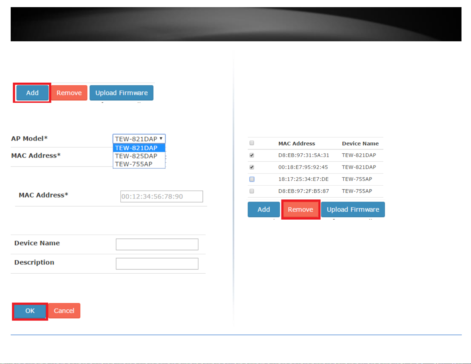
Manually add an access point
Configuration > Access Points
If an AP was not discovered automatically in the Monitor > Devices section, you can
manually add an AP by click Add.
Select the AP model in the drop-down list.
Enter the AP Ethernet/2.4G MAC address.
Enter the Device Name and Description so you can easily identify the AP. These are
optional parameters.
Remove access points from the controller
Configuration > Access Points
Once APs are added to the controller, they must be managed and configured through
the controller and can no longer be managed individually. APs must be
removed/disconnected from the controller or reset to default in order to regain
individual AP management access. When APs are removed from the controller, APs are
automatically reset to their factory default settings.
To remove an AP or multiple APs, check the APs you would like to remove in the left
column (The top check box will select all APs in the list), then click Remove. When
prompted, click Yes to confirm removal of the selected APs.
Click OK at the bottom to add the AP and assign the controller AP default settings,
otherwise modify the desired parameters first.
© Copyright 2017 TRENDnet. All Rights Reserved.

TRENDnet User’s Guide
TEW-755AP2KAC / TEW-821DAP2KAC
27
Access Point Model
Firmware version that adds the online firmware feature
through controller
TEW-755AP
1.04 or above
TEW-821DAP
1.06 or above
TEW-825DAP
1.02 or above
Simultaneously upgrade firmware for multiple access points
Configuration > Access Points
First, make sure you have downloaded the correct firmware for your APs and unzipped
to your local drive. The firmware file for the APs will have a .bin extension.
To simultaneously upgrade firmware for multiple APs, check the APs you would like to
upgrade firmware in the left column (The top check box will select all APs in the list),
then click Upload Firmware. When prompted, click Browse or Choose File (depending
your browser) and navigate to the location of the AP firmware (.bin file) and select it.
Once selected, click Upload to start the firmware upgrade process. Wait about 5
minutes for the process to complete.
Upgrade access point firmware using the online upgrade
The controller management page will display a notification if the new firmware upgrade
is available for your access points and provide you with the option to upgrade the
firmware via online through the controller management page.
*Note: Online upgrade feature available in controller firmware 2.02 and above. The
online firmware upgrade feature using the controller is available on only the access point
firmware versions in the table below. Any access point firmware prior to the versions
below must be upgraded manually by downloading firmware upgrade files available on
our website.
© Copyright 2017 TRENDnet. All Rights Reserved.
1. Log into your controller management page (see “Access you wireless controller
management page” on page 12).
2. Click on Configuration and click on Access Points.
3. If new firmware is available online, a notification will appear next to the current
access point firmware version.
4. Click the “New Update” notification for the access point you would like to update.

TRENDnet User’s Guide
TEW-755AP2KAC / TEW-821DAP2KAC
28
5. In the Online Firmware Update prompt, click OK to start the online firmware upgrade
process. Please wait for the firmware upgrade process to complete.
Note: By default, the Internal Memory settings is selected to temporarily download the
firmware files to the controller’s internal memory for the firmware upgrade process. If a
USB storage device is plugged into the controller’s USB port, the external storage device
will appear as an available storage location to download the firmware files for the
firmware upgrade process.
Please note the following:
Do not interrupt the firmware upgrade process. Do not turn off the device or
push the reset button during the firmware upgrade. Rebooting or resetting
during the firmware upgrade process may permanently damage your access
point.
6. During the online upgrade, messages will be displayed next to the current firmware
version to indicate the firmware upgrade status. After the firmware upgrade has
completed successfully, the new firmware version will be displayed.
Downloading – Indicates that the new firmware files are currently being
downloaded to the selected storage location.
Updating - Indicates that the device is currently being updated to the new
firmware.
Completed – Indicates that the firmware upgrade has completed
successfully.
Failed – Indicates that the firmware upgrade process failed.
Note: You can try the online firmware upgrade again or manually download the
firmware file from the TRENDnet website and upgrade the firmware manually.
© Copyright 2017 TRENDnet. All Rights Reserved.

TRENDnet User’s Guide
TEW-755AP2KAC / TEW-821DAP2KAC
29
Moving APs to a new controller
It is recommended to regularly back up the configuration of your wireless controller. In
the case of controller failure/replacement or adding a new controller to the network,
APs can be moved to other controllers to be management or restored to a replacement
controller unit. If a controller fails or is removed from the network, the APs will continue
to function and keep their current wireless settings. In order to restore the APs to a
replacement controller, (1) the controller IP settings must be configured to be on the
same IP network as the APs (2) you must use the administrator password configured on
the APs from the previous controller (same as the admin management password of
previous controller) to reassign the APs to the new controller (3) after you have
reassigned APs to the new controller successfully, you can restore your controller
configuration from a previous backup file. Whether reassigning new APs to a new
controller or replacing an existing controller, you can use the steps below to reassign
your APs.
Important Note: (1) the controller IP settings must be configured to be on the same IP
network as the APs (2) you must use the administrator password configured on the APs
from the previous controller (same as the admin management password of previous
controller) to reassign the APs to the new controller (3) after you have reassigned APs to
the new controller successfully, you can restore your controller configuration from a
previous backup file.
1. Log into your controller management page (see “Access you wireless controller
management page” on page 12).
2. Click on Monitor and click Devices and the connected APs will automatically appear in
the Device List as Lock status.
4. You will be prompted to enter the AP user name and password. Enter the AP user
name and password and click adopt. Note: This will be the same admin user name and
password of the previous controller that the AP was assigned.
5. After the AP has been successfully reassigned to the new controller, the AP status will
change from to in the list.
Note: If the AP is still in Lock status and is not successfully reassigned, the user name and
password entered may be incorrect. If the correct user name and password cannot be
recovered and use to reassign the AP, the AP must be reset to factory default in order to
reassign the APs to the current controller.
3. Under the Action column next to the AP you would like to reassign, click .
© Copyright 2017 TRENDnet. All Rights Reserved.

TRENDnet User’s Guide
TEW-755AP2KAC / TEW-821DAP2KAC
30
Wireless groups and profiles
Once APs are added to the controller, wireless profiles and security settings are
configured using wireless groups and no longer configured on each individual AP. A
wireless group consists of multiple APs or AP bands assigned to the specified wireless
group. APs should be separated and assigned by wireless group and multiple profiles can
be created within the wireless group for different purposes. For example, Wireless
Group 1 may be designated and located in a specific physical area (e.g. Lobby) and
Wireless Group 2 may be located in another physical area (e.g. Conference Rooms), etc.
For all of the APs in a single group, multiple profiles each consisting of SSID, wireless
security, roaming protocols, bandwidth control, VLAN, RSSI threshold, and guest captive
portal settings can be created for different purposes. For example, one group profile can
be configured for clients to connect to a specified VLAN and another for guest access
(Captive Portal). You can create up to 8 wireless profiles per wireless group.
Creating a wireless profile
Configuration > Wireless Groups/Profiles
Note: By default, when APs are added to the wireless controller, all APs will be assigned
to the default group “Default group”. You can create up to 8 wireless profiles per
wireless group.
1. Log into your controller management page (see “Access you wireless controller
management page” on page 12).
2. Click on Configuration and click Wireless Groups/Profiles.
Note: By default, the wireless group “Default group” has already been created. This
group cannot be deleted. The number next to the name (1) indicated the internal
group # assignment which is used for identification purposes under the Monitor >
Devices section.
3. To create a new wireless profile for “Default group”, in the list below, click Create.
4. Enter and select the parameters for the wireless profile. You can review the settings
below and click OK to add the new profile.
SSID – The wireless network name broadcasted for client devices to discover.
(e.g. TRENDnetWiFi)
Hide SSID – Enabling this setting will hide the wireless network name from
being discovered by client devices. Client can still connect to the wireless
network but may need to manually enter in the wireless connection details.
Captive Portal – Enabling this setting will require client devices to use special
captive portal authentication in order to connect to your wireless network. You
must configure the captive portal type and settings first before using this
feature. Please see the Captive Portal section first to configure the captive
portal settings before enabling this feature on your wireless profile.
Note: If using Captive Portal authentication, it is recommended to set the
Authentication method to None in the wireless profile settings since captive
portal authentication will be used instead.
Bandwidth Control – Check the option to enable bandwidth control. This
option allows you to specify the maximum download bandwidth limit for either
the SSID or each client device, upload can only be specified each client device.
The unit is specified in bits. Lowercase “m” can be used to specify Megabits
(e.g. 1m) and lowercase “k” can used to specify kilobits (e.g. 10k).
© Copyright 2017 TRENDnet. All Rights Reserved.

TRENDnet User’s Guide
TEW-755AP2KAC / TEW-821DAP2KAC
31
Roaming – Select which roaming protocols to enable for the wireless profile.
o 802.11k – This protocol enables the exchange of messages between
APs and client devices which includes utilization and signal strength
information of neighboring APs in the same wireless network. This
protocol can assist supported client devices in better roaming
decisions when transitioning between multiple APs in the same
wireless network. Client devices must support 802.11k in order to use
this feature but it can be safely enabled and functioning whether or
not client devices support this standard.
o 802.11r – This protocol allows client devices to pre-authenticate with
neighboring APs to significantly reduce the transition time or eliminate
the need for re-authentication during transition from one AP to
another. Client devices must support 802.11r in order to use this
feature and should not be enabled unless client devices support this
standard.
o OKC (Opportunistic Key Caching) – This protocol functions as a non-
standard version of 802.11r in allowing client devices to preauthenticate with neighboring APs. This protocol operates
independently on the controller and APs and does require client
devices to support any specific pre-authentication roaming standards.
This setting is recommended for the highest compatibility in order for
all client devices to benefit fast roaming transition across your wireless
network.
VLAN – Enable this option to assign a specific 802.1q VLAN tag or ID to the SSID
or wireless profile. By assigning a specific VLAN tag or ID, client devices that
connect to the profile, will be placed in the specified VLAN.
Note: 802.1q VLAN should be configured on your switch router and network
infrastructure to support use this feature.
RSSI Threshold – Enable this option set a signal strength limit on wireless client
devices when the AP will force the client to disconnect.
In a wireless roaming network with multiple access points, this feature can
assist by forcing the disconnection of the wireless client device before signal
strength and connectivity to the AP are too low to sustain enough bandwidth
for Internet streaming applications. This will force the wireless client device to
connect to another AP with a stronger signal and connection rate relative to it’s
new location. It is the nature of wireless client devices to maintain connectivity
to the currently connected AP as long as the signal can still be discovered.
In the example diagram, you can see that the further away the client device is
from the AP, the lower signal strength. (-30 RSSI is a higher strength value
relative to the AP compared to -90 RSSI). The client device at -90 RSSI is closer
to the next AP but without the forced disconnection from the AP on the left,
without the RSSI threshold function, the client device would remain connected
to the much further AP on the left than stronger signal AP on the right. Forcing
a disconnect from the originally connected AP on the right would force the
client to connect to the much higher signal strength AP on the right providing
better connectivity during the transition between physical locations.
© Copyright 2017 TRENDnet. All Rights Reserved.

TRENDnet User’s Guide
TEW-755AP2KAC / TEW-821DAP2KAC
32
WEP Key Format
HEX
ASCII
Character set
0-9 & A-F, a-f only
Alphanumeric (a,b,C,?,*, /,1,2, etc.)
64-bit key length
10 characters
5 characters
128-bit key length
26 characters
13 characters
Authentication Method – Select the authentication method used for the
profile.
o None – Does not require client devices to authentication or enter in
any security parameters to connect to the wireless network. Not
recommended for typical usage. Only recommended if using captive
portal authentication.
o WEP – Requires client devices to enter an unencrypted key to connect
to the wireless network. Only Key Index 1 is supported. Not
recommended since key is unencrypted and does not support 802.11n
and 802.11ac link rates.
o WPA/WPA2-PSK – Requires client devices to enter an encrypted
key/passphrase to connect to the wireless network. This is the
recommended setting.
Passphrase Format:8-63 alphanumeric characters (a,b,C,?,*, /,1,2, etc.)
o WPA/WPA2-Enterprise – Requires the configuration use of an
external RAIDIUS server for authentication through EAP (Extensible
Authentication Protocol). Depending on the EAP protocol configured
on the external RADIUS server, client devices will need to be
configured with the same authentication and credentials in order to
connect to the wireless network.
IP Address: Enter the IP address of the RADIUS server. (e.g.
192.168.10.250)
Port: Enter the port your RADIUS server is configured to use
for RADIUS authentication.
Note: It is recommended to use port 1812 which is the default
RADIUS port.
Shared Secret: Enter the shared secret used to authorize your
APs with your RADIUS server.
Below is an example of a single group configured with multiple wireless profiles.
4 x APs assigned to wireless group “Default group”
3 x wireless profiles created under “Default group”
All 4 APs will broadcast and allow connections for the 3 wireless profiles
created
4 x APs assigned to “Default group” will host these profiles and any new APs
added to the “Default group” will also host these profiles.
© Copyright 2017 TRENDnet. All Rights Reserved.

TRENDnet User’s Guide
TEW-755AP2KAC / TEW-821DAP2KAC
33
Creating a new wireless group
Configuration > Wireless Groups/Profiles
Creating separate wireless groups can allow you to organize and divide your access
points into smaller groups and categorize by designated physical locations,
departments, or other purposes to better isolate device troubleshooting and easily
implement extensions of network access control within your network.
Note: By default, when APs are added to the wireless controller, all APs will be assigned
to the default group “Default group”.
1. Log into your controller management page (see “Access you wireless controller
management page” on page 12).
2. Click on Configuration and click Wireless Groups/Profiles.
Note: By default, the wireless group “Default group” has already been created. This
group cannot be deleted. The number next to the name (1) indicated the internal
group # assignment which is used for identification purposes under the Monitor >
Devices section.
3. To create a new wireless group, next to the wireless group field, click Create (+).
assignment which is used for identification purposes under the Monitor > Devices
section. (e.g. Next group created would be assigned (3), next (4), and so on.)
Assigning access points to a wireless group
Configuration > Access Points
From the previous example “Creating a new wireless group”, this example will explain
how to assign an existing AP that has already been added to the controller into the
wireless group created.
1. Log into your controller management page (see “Access you wireless controller
management page” on page 12).
2. Click on Configuration and click Access Points and the list will display all of the APs
that have already been added to the wireless controller.
3. Select the AP you would like assign to the new group, and under the Action column,
click .
4.. In the field, enter a name for the group. (e.g. R&D) and the button to add the
new group.
5. The new group will be available in the wireless group drop-down list.
Note: Each group will automatically be assigned the new number in the order the
group was created. The number next to the name (2) indicated the internal group #
© Copyright 2017 TRENDnet. All Rights Reserved.
4. Under Radio B/G/N (2.4GHz), click the Wireless Group drop-down list and select the
new wireless group (e.g. R&D). If you have selected a dual band AP, select the same
group under Radio AC/N (5.0GHz) and click OK to save the changes.
Note: For dual band APs, each band can be assigned to a different wireless group for
more flexibility however, in most cases both bands will be assigned to the same AP group
since groups are typically organized by physical location.

TRENDnet User’s Guide
TEW-755AP2KAC / TEW-821DAP2KAC
34
5. To assign additional APs to the new group, repeat steps 3 & 4 and after you have
assigned all the desired APs to the new group, you can create wireless profiles under the
new wireless group.
6. To create new wireless profiles under the new wireless group, click on Configuration
and click Wireless Groups/Profiles.
7. In the Select Wireless Group drop-down list, select the new wireless group. (e.g. R&D)
8. To create a new wireless profile for the new group (e.g. R&D), in the list below, click
Create. For details on wireless profile settings, you can refer to the section “Creating a
wireless profile” on page 24.
Below is an example of 2 wireless groups with multiple wireless profiles from each
group.
2 x APs assigned to wireless group “Default group”
2 x APs assigned to wireless group “R&D”
3 x wireless profiles created under “Default group”
3 x wireless profiles created under “R&D”
2 x APs will broadcast and allow connections for the 3 wireless profiles created
under “Default group”
2 x APs will broadcast and allow connections for the 3 wireless profiles created
under “R&D”
© Copyright 2017 TRENDnet. All Rights Reserved.

TRENDnet User’s Guide
TEW-755AP2KAC / TEW-821DAP2KAC
35
Captive Portal
The captive portal feature allows you to provide customized authentication typically for
public WiFi users and guest user authentication. Captive Portal authentication is
typically used in areas such as hotel lobbies, airports, coffee shops and other WiFi hot
spots. The access points support both captive portal authentication through the built-in
user account database which includes basic portal customization or CoovaChlli which is
an open-source implementation of captive portal (UAM) function and 802.1X RADIUS
(please note CoovaChilli requires an external CoovaChilli server which must be
preconfigured to work and authenticate requests through the access point). The access
points also support URL/web page redirect without authentication for advertisement
purposes. The captive portal functionality of the access points can be managed through
the wireless controller and applied to select wireless profiles as desired. It is
recommended to disable standard WiFi security methods such as WEP/WPA/WPA2 in
order to use the captive portal authentication method instead on selected wireless
profiles. Before applying captive portal functionality to select wireless profiles, the
captive portal type must be configured first along with all required parameters.
Log into your controller management page (see “Access you wireless controller
management page” on page 12).
Click on Configuration and click Captive Portal and check Enable Captive Portal.
Select the Portal Mode:
Note: Only one mode can be used, multiple modes cannot be used at the same time.
To Internal Portal URL – This mode allows you to authenticate requests
through the built-in user account database and apply basic customization to
the captive port user login page. This option is recommended and does not
require an external authentication server.
To Advertisement URL – This mode requires no authentication and allows
redirection of users to a specific website/URL only.
Captive Portal with RADIUS (CoovaChilli) – This mode requires an external
CoovaChilli server to be configured to provide the captive portal user login
page and authenticate request through the access point.
A. To Internal Portal URL
Configuration > Captive Portal
Choose the option To Internal Portal URL.
a. First, select the login authentication method for connecting your captive portal WiFi
network. At the Login Method drop-down list, select one of the following.
User name and password – Requires users to enter a user name and password
for authentication to connect to your captive portal WiFi network which must
be defined in the User List.
o To create a new user account, next to Setting Username and
Password, enter the user name and password for the new user
account and click Add. Repeat to add more user accounts.
Single password – Requires users to enter a single password to connect your
captive portal WiFi network which must be defined in the Setting Single
Password settings.
o To specify a single password, next to Setting Single Password, enter
the new password or click Generate to randomly generate a new
password.
Both – Users can enter either a user name and password or single password to
connect to your captive portal WiFi network. Both prompts will be displayed on
the captive portal page and user can select either method to authenticate.
© Copyright 2017 TRENDnet. All Rights Reserved.

TRENDnet User’s Guide
TEW-755AP2KAC / TEW-821DAP2KAC
36
b. Next, specify the Authentication Timeout settings. This is the session time period
(minutes) which users are allowed to be logged in to your wireless network. Once the
time expires, users will automatically logged and will need to log back in through the
captive portal page again in order to reconnect to your wireless network. It is
recommended to set a value to ensure authentication sessions are closed after a certain
time period. Setting the value to 0 minutes allows users to be authenticated and
connected to your captive portal WiFi network without any time restrictions.
c. Click Apply at the bottom of the page to save the initial captive portal authentication
settings.
Add an advertisement or redirect URL/address/website
After your users authenticate and connect to your captive portal WiFi network, you may
want to redirect your users to a specific URL, address, or website for advertisement
purposes.
Check the Advertisement URL Enable setting and enter the URL/address/website in the
field Enter Advertisement URL. Click Apply at the bottom of the page to save the
settings.
Note: The prefix http:// or https:// must be included when entering
URLs/addresses/websites (ex. https://www.trendnet.com)
© Copyright 2017 TRENDnet. All Rights Reserved.
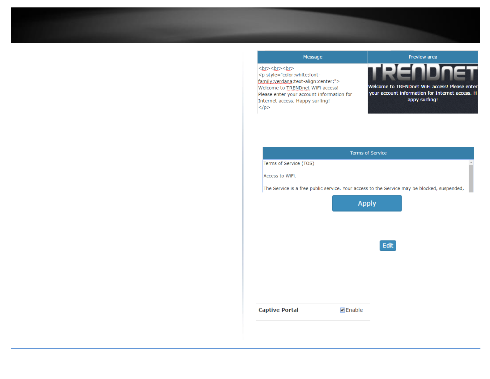
TRENDnet User’s Guide
TEW-755AP2KAC / TEW-821DAP2KAC
37
Customize your internal captive portal page
After you have defined the initial parameters, you can apply basic portal page
customization.
Under Upload Image File, click Browse or Choose File depending on your browser, and
navigate to the directory where the selected image is located and select the image.
Once you have selected the image, click Upload.
Once you have uploaded the image, an image preview will appear and you can assign
the image Set as background or Set as logo. If you would like to delete the image and
upload a different image, you can also click Delete to delete the image.
Note: Only 2 images can be uploaded for portal page customization (Only one image can
be set for the portal page background and another image can be set for the
company/organization logo). Images are automatically scaled when uploaded. The
recommended image formats are JPG, PNG, GIF. Maximum file size for images is 250KB.
After you have uploaded your images, you can add a welcome or greeting message to
display to your guest users on the captive portal page. A preview of the page and text
will also be displayed. After you have finished entering your message, click Apply.
Note: Aside from text, you can enter HTML tags for text formatting and styles.
Below is an example of a greeting message formatted in html.
<br><br><br>
<p style="color:white;font-family:verdana;text-align:center;">
Welcome to TRENDnet WiFi access!
Please enter your account information for Internet access. Happy surfing!
</p>
Additionally, you can modify the text displayed to your users for your terms of service.
By default, a generic terms of service statement is provided for reference.
To apply captive portal authentication to a wireless profile, click on Configuration and
click on Wireless Groups/Profiles. Select the wireless group where the desired wireless
profile is located under the Action column click to configure the profile. For
the captive portal setting, check the Enable option. Click OK.
Note: If using Captive Portal authentication, it is recommended to set the Authentication
method to None in the wireless profile settings since captive portal authentication will be
used instead. If the Authentication Method is left enabled, the users will need to
authenticate twice, once with the authentication method defined and also captive portal
authentication.
© Copyright 2017 TRENDnet. All Rights Reserved.

TRENDnet User’s Guide
TEW-755AP2KAC / TEW-821DAP2KAC
38
B. To Advertisement URL
Configuration > Captive Portal
Choose the option To Advertisement URL.
First, enter the authentication timeout value and the advertisement URL and click Apply
to save the settings.
Advertisement URL – This is the website or URL guest users will be
automatically redirected after connecting to your wireless network through
your captive portal page.
Note: The prefix http:// or https:// must be included when entering
URLs/addresses/websites (ex. https://www.trendnet.com )
After you have defined the initial parameters, you can apply portal page customization.
Under Upload Image File, click Browse or Choose File depending on your browser, and
navigate to the directory where the selected image is located and select the image.
Once you have selected the image, click Upload.
Once you have uploaded the image, an image preview will appear and you can assign
the image Set as background or Set as logo. If you would like to delete the image and
upload a different image, you can also click Delete to delete the image.
Note: Only 2 images can be uploaded for portal page customization (Only one image can
be set for the portal page background and another image can be set for the
company/organization logo). Images are automatically scaled when uploaded. The
recommended image formats are JPEG, PNG, GIF. Maximum file size for images is
250KB.
After you have uploaded your images, you can add a welcome or greeting message to
display to your guest users on the captive portal page. A preview of the page and text
will also be displayed. After you have finished entering your message, click Apply.
Note: Aside from text, you can enter HTML tags for text formatting and styles.
Below is an example of a greeting message formatted in html.
<br><br><br>
© Copyright 2017 TRENDnet. All Rights Reserved.
<p style="color:white;font-family:verdana;text-align:center;">
Welcome to TRENDnet WiFi access!
Please enter your account information for Internet access. Happy surfing!
</p>
Additionally, you can modify the text displayed to your users for your terms of service.
By default, a generic terms of service statement is provided for reference.
To apply captive portal authentication to a wireless profile, click on Configuration and
click on Wireless Groups/Profiles. Select the wireless group where the desired wireless
profile is located under the Action column click to configure the profile. For
the captive portal setting, check the Enable option. Click OK.
Note: If using Captive Portal authentication, it is recommended to set the Authentication
method to None in the wireless profile settings since captive portal authentication will be
used instead. If the Authentication Method is left enabled, the users will need to
authenticate twice, once with the authentication method defined and also captive portal
authentication.
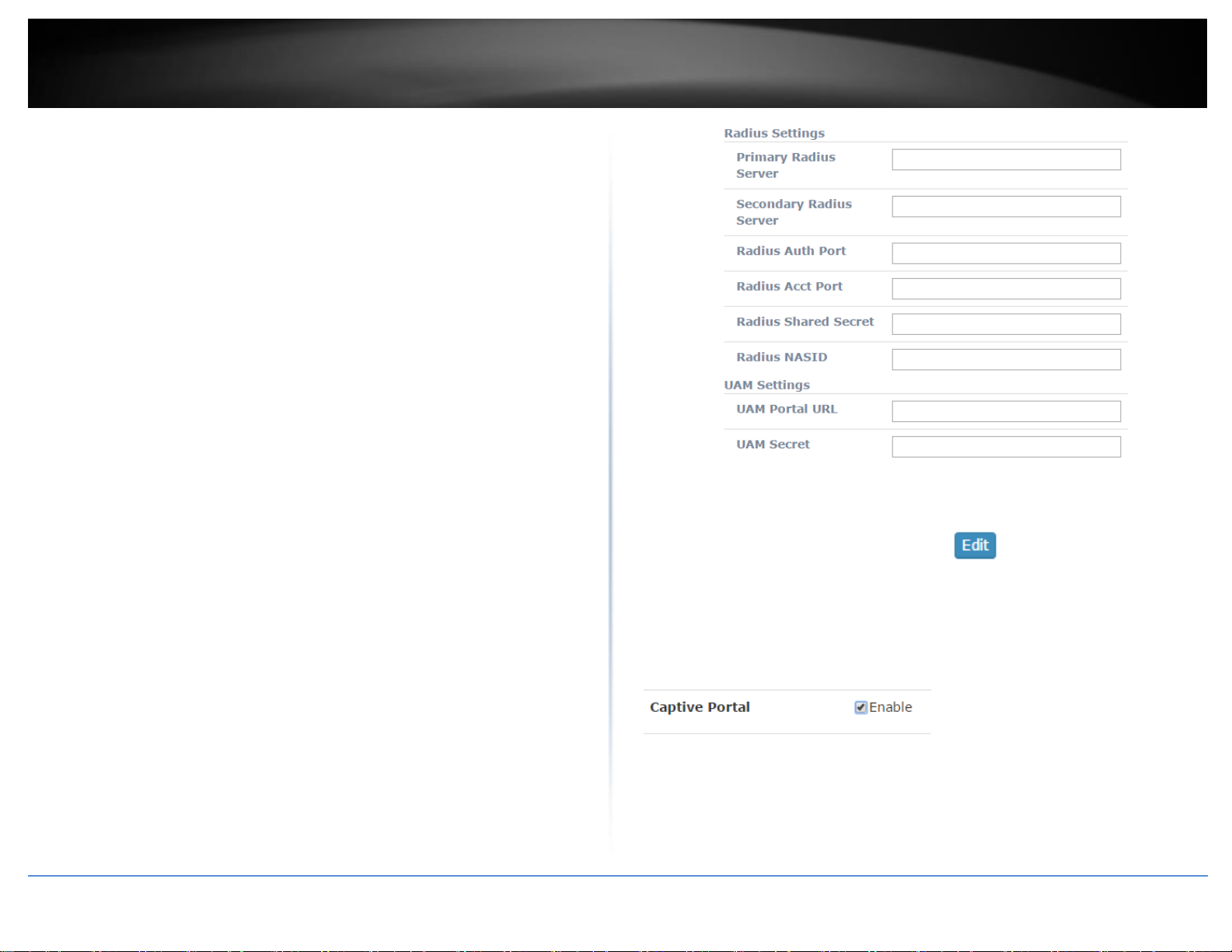
TRENDnet User’s Guide
TEW-755AP2KAC / TEW-821DAP2KAC
39
C. Captive Portal with RADIUS (CoovaChilli)
Configuration > Captive Portal
Choose the option Captive Portal with RADIUS.
Note: Since the option requires the use of an external RADIUS/CoovaChilli server for
authentication, please make sure it is set up, configured and available on your network
accessible by your controller and APs.
Enter the CoovaChilli server settings. Click OK.
Primary RADIUS Server – Enter the IP address of the external CoovaChilli
authentication server.
Secondary RADIUS Server – If you have secondary or backup CoovaChilli
authentication server, enter the IP address.
RADIUS Auth Port – Enter the port number used by the Coovachilli server for
authenticating RADIUS requests. The default port number used for RADIUS
authentication is 1812.
RADIUS Acct Port – Enter the port number used by the Coovachilli server for
accounting on the server. The default port number for RAIDUS accounting is
1813.
RADIUS Shared Secret – Enter the shared secret used to allow the CoovaChilli
server to allow the access point to authentication RADIUS authentication
requests.
RADIUS NAS ID: Enter the NAS ID required by the CoovaChilli server to allow
the access point to authentication RADIUS authentication requests.
UAM Portal URL – Enter the UAM portal web URL address of the login
authentication page provided by the CoovaChilli server.
UAM Secret – Enter the UAM secret required to allow access to this portal
page.
To apply captive portal authentication to a wireless profile, click on Configuration and
click on Wireless Groups/Profiles. Select the wireless group where the desired wireless
profile is located under the Action column click to configure the profile. For
the captive portal setting, check the Enable option. Click OK.
Note: If using Captive Portal authentication, it is recommended to set the Authentication
method to None in the wireless profile settings since captive portal authentication will be
used instead. If the Authentication Method is left enabled, the users will need to
authenticate twice, once with the authentication method defined and also captive portal
authentication.
© Copyright 2017 TRENDnet. All Rights Reserved.

TRENDnet User’s Guide
TEW-755AP2KAC / TEW-821DAP2KAC
40
WAP Maps™
The WAP (wireless access point) maps feature allows you to upload a floor plan (JPEG,
PNG, or GIF) to the wireless controller and place your APs on your floor plan for AP
location planning and reference.
Note: For optimal viewing, it is recommended to use a base image size of 970px x 520px
(max.) for all uploaded floor plans and the actual layout drawings within 920 x 470px
(max.).
Floor plan image size reference
Upload floor plans
Monitor > WAP Maps™
1. Log into your controller management page (see “Access you wireless controller
management page” on page 12).
2. Click on Monitor and click WAP Maps™.
3. In the Map Name field, enter a name to easily identify the map in the list.
Click Browse or Choose File depending on your browser and navigate to the directory
where the floor plan image you would like to upload. Once the desired floor plan image
is selected, click Upload.
4. Once the floor plan is uploaded, you can drag and drop the available APs located on
the left side to the area where the APs will be located on your floor plan.
The APs are listed by MAC address. When hovering over an AP with your cursor, the
MAC address and Device Name will be displayed. The color of the AP icon indicates the
current AP status as below which can also be seen on the Monitor > Devices page.
Status – Displays the current AP status.
o NEW - The AP has not been added to any other wireless
controllers and is available to add to the currently managed controller.
o RUN - The AP has been successfully added to the currently
managed wireless controller. When APs are added to the controller,
they can no longer be managed individually, only managed through
the controller. APs will need to be removed from the controller in
order to be individually managed.
o OFF - The AP has been added to the currently managed wireless
controller but AP is offline.
o LOCK - The AP has been added to another wireless controller
and is not available to add to the currently managed controller. When
APs are added to the controller, they can no longer be managed
individually, only managed through the controller they have been
added. APs will need to be removed from the controller in order to be
individually managed.
© Copyright 2017 TRENDnet. All Rights Reserved.

TRENDnet User’s Guide
TEW-755AP2KAC / TEW-821DAP2KAC
41
When double clicking the AP icon, additional options will appear.
– Clicking this option will display a summarized list of information
about the AP.
o Locate – If the AP has been marked on a previously uploaded WAP
Map floorplan, clicking this link will reopen the floorplan.
o Reboot – Clicking this link will reboot the AP.
– Clicking this option displays a brief snapshot of the total amount of
data downloaded (received) by the AP over the last 5 minutes in graph form.
o Locate – If the AP has been marked on a previously uploaded WAP
Map floorplan, clicking this link will reopen the floorplan.
o Reboot – Clicking this link will reboot the AP.
- Click this option will remove the AP from the location on the floorplan
and the AP will be moved back to the list of available APs on the left side.
Deleting and resetting floor plans
To delete a map, click on the Select Map drop-down list and select the map to delete.
Click Delete to delete the floor plan.
Clicking Reset will reset the floor plan and remove all the access points that were added
to the floor plan.
© Copyright 2017 TRENDnet. All Rights Reserved.
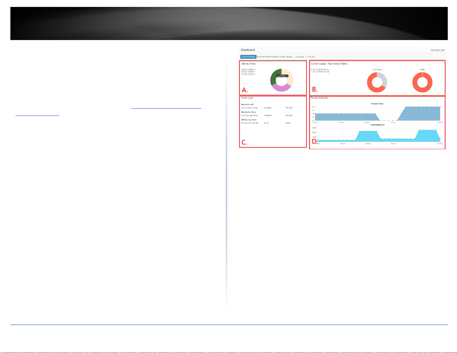
TRENDnet User’s Guide
TEW-755AP2KAC / TEW-821DAP2KAC
42
Monitoring access points and clients
Viewing the controller dashboard
Monitor > Dashboard
The dashboard displays an overview of the most recent activity for APs, clients, and data
usage over time.
1. Log into your controller management page (see “Access you wireless controller
management page” on page 12).
2. Click on Monitor and click Dashboard.
Period of Time for Display – You can select the most recent time interval time
interval of data to display on the entire dashboard: most recent 5 minutes, 1
hour, or 1 day for monitoring. You can also click Stop Monitoring to stop the
controller from collecting or monitoring any new data.
A. Clients (Total) – This section will display a list top 5 wireless profile SSIDs
with highest amount of data usage/activity. When hovering over with
your cursor, the SSID name and total number of data
transmitted/received will be displayed.
B. Current Usage (Top Access Points) – This section will display the top 5
access points with the highest amount of data usage/activity. When
hovering over with your cursor, the AP MAC address and total number
of packets transmitted/received will be displayed.
C. Quick Look – This section will display the AP with the most recent
activity, client with the most recent activity, and client with the highest
amount of data usage.
D. Recent Activities – This section displays a chart of the most recent
activity. The Clients (Total) chart displays the total number of clients
over the most recent time interval. The Traffic (Mbytes) chart displays
the total number of packets transmitted on all APs over the most recent
time interval.
© Copyright 2017 TRENDnet. All Rights Reserved.
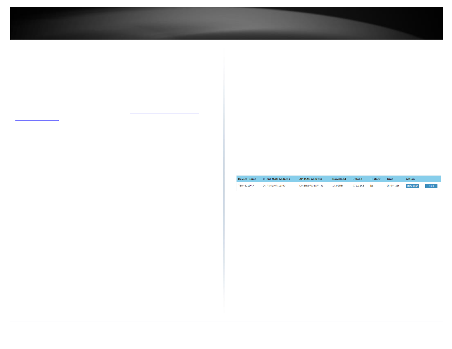
TRENDnet User’s Guide
TEW-755AP2KAC / TEW-821DAP2KAC
43
View client connections
Monitor > Clients
The controller allows you to monitor all of the currently connected client devices.
Additionally, the client blacklist feature allows you to permanently block specific client
devices that are currently connected to your wireless network. The client blacklist
prevents/restricts any specified client devices from accessing your wireless network in
the future unless they are removed from the blacklist.
1. Log into your controller management page (see “Access you wireless controller
management page” on page 12).
2. Click on Monitor and click Clients.
3. In the Client List, the currently connected client devices will be listed along with some
additional information.
Device Name – Displays the device name of the AP the client is currently
connected.
Client MAC Address – Displays the MAC address of the client device.
AP MAC Address – Displays the MAC address of the AP the client is currently
connected.
Download – Displays the current total of data downloaded (received) by the
client device in bytes (B).
Upload – Displays the current total of data downloaded (transmitted) by the
client device in bytes (B).
History – Clicking this option displays a brief snapshot of the total amount of
data downloaded (received) by the client device over the last 5 minutes in
graph form.
Time – Displays the total amount of time the client device has been connected
Action
o Blacklist – Clicking this option will add the client device to the client
blacklist. To view the client blacklist, click on Configuration > Client
Blacklist. Clients that are added to the client blacklist will be
permanently blocked from any APs managed by the wireless controller
until they are removed the client blacklist.
o Kick – Clicking this option will force the AP to immediately disconnect
the client device from the wireless network.
to the wireless network.
o Blacklist – Clicking this option will add the client device to the client
blacklist. To view the client blacklist, click on Configuration > Client
Blacklist. Clients that are added to the client blacklist will be
permanently blocked from any APs managed by the wireless controller
until they are removed the client blacklist.
o Kick – Clicking this option will force the AP to immediately disconnect
the client device from the wireless network.
© Copyright 2017 TRENDnet. All Rights Reserved.

TRENDnet User’s Guide
TEW-755AP2KAC / TEW-821DAP2KAC
44
Technical Specifications
Wireless Controller (TEW-WLC100)
Standards
IEEE 802.3
IEEE 802.3u
IEEE 802.3x
IEEE 802.3ab
Device Interface
5 x Gigabit ports
1 x USB port
On/Off Power button
LED indicators
Reset button
Management
HTTP Web based GUI
Local or online firmware upgrade
Internal log
Configuration Backup/Restore
NTP
Access Point Management
Manage up to 128 access points
IP address, gateway, and DNS settings
SSID/Network name
Wireless channel
Wireless encryption: WEP, WPA/WPA2-Personal, WPA/WPA2-Enterprise
802.11 mode
Channel width
Transmit power
SSID broadcast
Bandwidth control (download limit per SSID & client, upload limit per client)
Set RSSI scanning/threshold
Seamless WiFi roaming using 802.11r and OKC (opportunistic key caching)
protocols
802.11k radio resource management
Airtime Fairness
Band steering
Access point/client statistics monitoring
Batch firmware upgrade deployment
Captive portal
Client blacklist
802.1Q VLAN
Create multiple access point groups for management flexibility
Upload custom floor plans using WAP Maps™
Access Point Compatibility
TEW-755AP (Firmware Version: 1.04 or above)
TEW-821DAP (Firmware Version: 1.06 or above)
TEW-825DAP (Firmware Version: 1.02 or above)
Power
Input: 100 – 240 V AC, 50/60 Hz
Output: 12V DC, 1A external power adapter
Consumption: 12W (max.)
Operating Temperature
0 – 40°C (32 – 104°F)
Operating Humidity
Max. 90% non-condensing
Dimensions
215 x 130 x 44.45 mm (8.27 x 6.3 x 1.73 in.)
Rack mountable 1U height
Weight
670 g (1.5 lbs.)
Certifications
CE
FCC
© Copyright 2017 TRENDnet. All Rights Reserved.

TRENDnet User’s Guide
TEW-755AP2KAC / TEW-821DAP2KAC
45
N300 PoE Access Point (TEW-755AP)
Standards
IEEE 802.1Q
IEEE 802.3
IEEE 802.3u
IEEE 802.3x
IEEE 802.3ab
IEEE 802.3af
IEEE 802.11b
IEEE 802.11g
IEEE 802.11n (up to 300 Mbps)
Device Interface
1 x PoE Gigabit LAN port
Power port (optional non-PoE installation)
Reset button
LED indicators
Mounting plate
Special Features
IP30 rated housing (with mounting plate installed)
WiFi traffic shaping
802.1Q VLAN assignment per SSID
IPv6 support (Link-Local, Static IPv6, Auto-Configuration (SLAAC/DHCPv6)
Multi-Language interface, English, French, Spanish, German, Russian
LEDs on/off
Captive Portal (External Coovachilli server authentication)
Internal Captive Portal (Local user account authentication and customizable
portal page)
802.11k radio resource management
RSSI Scanner (Client signal strength and tolerance)
Airtime Fairness
Operation Modes
Access Point
Client
WDS AP
© Copyright 2017 TRENDnet. All Rights Reserved.
WDS Bridge
WDS Station
Repeater
Management/Monitoring
Web based management
SNMP v1/v3
STP
Event logging
Ping test
Traceroute
CLI
Access Control
Wireless encryption: WEP, WPA/WPA2-PSK, WPA/WPA2-RADIUS
MAC filter
Maximum client limit
QoS
WMM
Traffic shaping per SSID
SSID
Up to 8 SSIDs per access point
Frequency
2.4 GHz: 2.412 - 2.472 GHz
Wireless Channels
2.4 GHz: FCC: 1-11, ETSI: 1 – 13
Modulation
DBPSK/DQPSK/CCK for DSSS technique
BPSK/QPSK/16-QAM/64-QAM for OFDM technique
Antenna Gain
2.4 GHz: 2 x 4 dBi

TRENDnet User’s Guide
TEW-755AP2KAC / TEW-821DAP2KAC
46
Wireless Output Power/Receiving Sensitivity
802.11b: FCC: 23 dBm (Max.), CE: 10 dBm (Max) / -83 dBm (typical) @ 11 Mbps
802.11g: 19 dBm (Max.), CE: 12 dBm (Max.) / -65 dBm (typical) @ 54 Mbps
802.11n: FCC: 19 dBm (Max.), CE: 12 dBm (Max.) / -64 dBm (typical) @ 300
Mbps
Power
12 V DC/ 1 A or PoE, consumption: 9.6 Watts Max.
Operating Temperature
0 – 40 °C (32 – 104 °F)
Operating Humidity
Max. 95 % non-condensing
Dimensions
187 x 187 x 46 mm (7.3 x 7.3 x 1.8 in.) per access point
Weight
402 g (14.2 oz.) per access point
Certifications
CE
FCC
IC
© Copyright 2017 TRENDnet. All Rights Reserved.
AC1200 Dual Band PoE Access Point (TEW-821DAP)
Standards
IEEE 802.1Q
IEEE 802.3
IEEE 802.3u
IEEE 802.3x
IEEE 802.3ab
IEEE 802.3af
IEEE 802.11a
IEEE 802.11b
IEEE 802.11g
IEEE 802.11n (up to 300 Mbps)
IEEE 802.11ac (up to 867 Mbps)
Device Interface
1 x PoE Gigabit LAN port
Power port (optional non-PoE installation)
Reset button
LED indicators
Mounting plate
Special Features
IP30 rated housing (with mounting plate installed)
Concurrent Dual band
Band Steering
WiFi traffic shaping
802.1Q VLAN assignment per SSID
IPv6 support (Link-Local, Static IPv6, Auto-Configuration (SLAAC/DHCPv6)
Multi-Language interface, English, French, Spanish, German, Russian
LEDs on/off
Captive Portal (External Coovachilli server authentication)
Internal Captive Portal (Local user account authentication and customizable
portal page)
802.11k radio resource management
Airtime Fairness
RSSI Scanner (Client signal strength and tolerance)

TRENDnet User’s Guide
TEW-755AP2KAC / TEW-821DAP2KAC
47
Operation Modes
Access Point
Client
WDS AP
WDS Bridge
WDS Station
Repeater
Management/Monitoring
Web based management
SNMP v1/v3
STP
Event logging
Ping test
Traceroute
CLI
Access Control
Wireless encryption: WEP, WPA/WPA2-PSK, WPA/WPA2-RADIUS
MAC filter
Maximum client limit
QoS
WMM
Traffic shaping per SSID
SSID
Up to 8 SSIDs per wireless band (16 total) per access point
Frequency
2.4 GHz: 2.412 - 2.472 GHz
5 GHz: 5.180 – 5.8525 GHz
Wireless Channels
2.4 GHz: FCC: 1-11, ETSI: 1 – 13
5 GHz: FCC: 36, 40, 44, 48, 149, 153, 157, 161 and 165 ETSI: 36, 40, 44, 48 (52,
56, 60, 64, 100,104,108,112,116, 132,136,140)***
Modulation
DBPSK/DQPSK/CCK for DSSS technique
BPSK/QPSK/16-QAM/64-QAM/256-QAM for OFDM technique
Antenna Gain
2.4 GHz: 2 x 4 dBi
5 GHz: 2 x 4 dBi
Wireless Output Power/Receiving Sensitivity
802.11a: FCC: 24 dBm, CE: 22 dBm (Max.) /-65 dBm (typical) @ 54 Mbps
802.11b: FCC: 23 dBm (Max.), CE: 10 dBm (Max) /-83 dBm (typical) @ 11 Mbps
802.11g: 19 dBm (Max.), CE: 12 dBm (Max.) /-65 dBm (typical) @ 54 Mbps
802.11n: FCC: 19 dBm (Max.), CE: 12 dBm (Max.) /-64 dBm (typical) @ 300
Mbps 2.4 GHz
802.11n: FCC: 24 dBm, CE: 22 dBm (Max.)/-61 dBm (typical) @ 300 Mbps 5 GHz
802.11ac: FCC: 15 dBm, CE: 22 dBm (Max.)/-51 dBm (typical) @ 867 Mbps
Power
12 V DC/ 1 A or PoE, consumption: 9.6 Watts Max.
Operating Temperature
0 – 40 °C (32 – 104 °F)
Operating Humidity
Max. 95 % non-condensing
Dimensions
187 x 187 x 46 mm (7.3 x 7.3 x 1.8 in.) per access point
Weight
408 g (14.4 oz.) per access point
Certifications
CE
FCC
IC
© Copyright 2017 TRENDnet. All Rights Reserved.

TRENDnet User’s Guide
TEW-755AP2KAC / TEW-821DAP2KAC
48
Gigabit PoE Injector (TPE-113GI)
Standards
IEEE 802.3 10Base-T
IEEE 802.3u 100Base-TX
IEEE 802.3ab Gigabit Ethernet
IEEE 802.3af Power over Ethernet
Network Media
10 Mbps: UTP/STP Cat. 5 and 5e up to 100 Meters
100 Mbps: UTP/STP Cat. 5, and 5e up to 100 Meters
Gigabit: UTP/STP Cat 5e and 6 up to 100 meters
Ports
1 x 10/100/1000 Mbps DATA-IN (Data only)
1 x 10/100/1000 Mbps PWR+DATA OUT (Data + Power)
Data Lines
Pair 1: Pin 1, 2
Pair 2: Pin 3, 6
Power
Input: 100~240V, 50~60Hz, 0.4A max.
Output: 48V DC, 0.5A 18W max.
Power Consumption
15.4 Watts (max.)
Dimensions (W x D x H)
70 x 45 x 25mm (2.75 x 1.8 x 1 in.)
Weight
45 g (1.6 oz.)
Temperature
Operation: 0°C~50°C (32°F~ 122°F)
Storage: -20°C~60°C (-4°F~140 °F)
Humidity
Max. 90% (non-condensing)
Certifications
CE
FCC
Disclaimers
*For wireless controller compatibility, access points must have the corresponding
firmware versions listed below.
TEW-755AP (Firmware Version: 1.04 or above)
TEW-821DAP (Firmware Version: 1.06 or above)
TEW-825DAP (Firmware Version: 1.02 or above)
**Maximum wireless signal rates are referenced from IEEE 802.11 theoretical
specifications. Actual data throughput and coverage will vary depending on
interference, network traffic, building materials and other conditions.
***Due to regulatory requirements, the wireless channels specified cannot be statically
assigned, but will be available within the available wireless channels when set to auto.
© Copyright 2017 TRENDnet. All Rights Reserved.

TRENDnet User’s Guide
TEW-755AP2KAC / TEW-821DAP2KAC
49
Troubleshooting
Q1: How do I configure my computer’s network adapter with a static IP address?
Note: Please note that although the following procedures are provided to follow for your
operating system network adapter settings to be used as general guidelines, however, it
is strongly recommended that you consult your computer or operating system
manufacturer directly for assistance on the proper procedure for configuring network
settings. If you are experiencing difficulties, please contact your computer or operating
system manufacturer for assistance.
Windows 2000/XP/Vista/7/8/8.1/10
a. On your keyboard, press Windows Logo + R keys simultaneously to bring up
the Run dialog box.
b. In the dialog box, type ncpa.cpl to bring up the Network Connections
window.
c. Right-click the Local Area Connection or Ethernet icon, click Properties, and
double-click Internet Protocol Version 4 (TCP/IPv4).
d. Then click Use the following IP address and assign your network adapter a
static IP address.
(See example static IP address settings below)
IP address: 192.168.10.25
Subnet mask: 255.255.255.0
e. Click OK on both TCP/IPv4 Properties and Local Area Connection Properties
windows.
MAC OS X
a. From the Apple drop-down list, select System Preferences.
b. Click the Network icon.
c. From the Location drop-down list, select Automatic.
d. Select and view your Ethernet connection.
In MAC OS 10.4, from the Show drop-down list, select Built-in
Ethernet and select the TCP/IP tab
In MAC OS 10.5 and above, in the left column, select Ethernet.
e. Configure TCP/IP to use a static IP.
settings.
Q2: I configured my computer’s network adapter with a static IP address, how do I
reconfigure my computer’s network adapter to default settings and obtain an IP
address automatically using DHCP?
Note: Please note that although the following procedures are provided to follow for your
operating system network adapter settings to be used as general guidelines, however, it
is strongly recommended that you consult your computer or operating system
manufacturer directly for assistance on the proper procedure for configuring network
settings. If you are experiencing difficulties, please contact your computer or operating
system manufacturer for assistance.
Windows 2000/XP/Vista/7/8/8.1/10
a. On your keyboard, press Windows Logo + R keys simultaneously to bring up
the Run dialog box.
b. In the dialog box, type ncpa.cpl to bring up the Network Connections
window.
MAC OS X
From the Configure IPv4 or Configure drop-down list, select Manually
and assign your network adapter a static IP address. Then click the
Apply or Apply Now button.
(See example static IP address settings below)
IP address: 192.168.10.25
Subnet mask: 255.255.255.0
f. You may be prompted to restart your computer to apply the new IP address
c. Right-click the Local Area Connection or Ethernet icon, click Properties, and
double-click Internet Protocol Version 4 (TCP/IPv4).
d. Then click Obtain an IP address automatically and Obtain DNS server
address automatically.
e. Click OK on both TCP/IPv4 Properties and Local Area Connection Properties
windows.
a. From the Apple drop-down list, select System Preferences.
b. Click the Network icon.
© Copyright 2017 TRENDnet. All Rights Reserved.

TRENDnet User’s Guide
TEW-755AP2KAC / TEW-821DAP2KAC
50
c. From the Location drop-down list, select Automatic.
d. Select and view your Ethernet connection.
In MAC OS 10.4, from the Show drop-down list, select Built-in
Ethernet and select the TCP/IP tab.
In MAC OS 10.5 and above, in the left column, select Ethernet.
e. Configure TCP/IP to use a static IP.
From the Configure IPv4 or Configure drop-down list, select Using
DHCP and click the Apply or Apply Now button.
f. You may be prompted to restart your computer to apply the new IP address
settings.
Q3: I typed http://192.168.10.200 in my Internet Browser Address Bar, but an error
message says “The page cannot be displayed.” How can I access the wireless controller
management page?
Answer:
a. Double check all physical cable and port connections.
b. Make sure the POWER/SYSTEM LED on the wireless controller front panel is
on.
c. Make sure your computer’s network adapter is configured with a static IP
address. (Refer to Q1 for instructions on assigning a static IP address).
d. Make sure your computer is connected to one of the Ethernet ports 1-5.
e. Since the switch default IP address is 192.168.10.200, make sure there are
no other network devices assigned an IP address of 192.168.10.200
Note: After checking all of the recommended items above, please attempt to
access the wireless controller management page again.
Q4: I changed the IP address of the wireless controller, but I forgot it. How do I reset
my wireless controller to factory default?
Answer:
Using a paper clip, push and hold the reset button on the rear panel of the wireless
controller and release after 15 seconds. The default IP address of the switch is
192.168.10.200. The default user name and password is “admin”.
Q5: How do I find the current IP address of my computer’s network adapter?
Answer:
Note: Please note that although the following procedures are provided to follow for your
operating system network adapter settings to be used as general guidelines, however, it
is strongly recommended that you consult your computer or operating system
manufacturer directly for assistance on the proper procedure for configuring network
settings. If you are experiencing difficulties, please contact your computer or operating
system manufacturer for assistance.
Command Prompt Method
Windows 2000/XP/Vista/7/8/8.1/10
a. On your keyboard, press Windows Logo+R keys simultaneously to bring up
the Run dialog box.
b. In the dialog box, type cmd to bring up the command prompt.
c. In the command prompt, type ipconfig /all to display your IP address
settings.
MAC OS X
a. Navigate to your Applications folder and open Utilities.
b. Double-click on Terminal to launch the command prompt.
c. In the command prompt, type ipconfig getifaddr <en0 or en1> to display the
wired or wireless IP address settings.
Note: en0 is typically the wired Ethernet and en1 is typically the wireless Airport
interface.
© Copyright 2017 TRENDnet. All Rights Reserved.

TRENDnet User’s Guide
TEW-755AP2KAC / TEW-821DAP2KAC
51
Graphical Method
Windows XP/Vista/7/8/8.1/10
a. On your keyboard, press Windows Logo + R keys simultaneously to bring up
the Run dialog box.
b. In the dialog box, type ncpa.cpl to bring up the Network Connections
window.
c. Double-click the Local Area Connection icon and click the Details button to
view the current IP address settings.
Note: The computer’s network adapter must be enabled and connected to view
the current IP address settings.
MAC OS X
a. From the Apple menu, select System Preferences.
b. In System Preferences, from the View menu, select Network.
© Copyright 2017 TRENDnet. All Rights Reserved.

TRENDnet User’s Guide
TEW-755AP2KAC / TEW-821DAP2KAC
52
Security Standard
WEP
WPA
WPA2
Compatible
Wireless
Standards
IEEE 802.11a/b/g
(802.11n devices
will operate at
802.11g to connect
using this standard)
IEEE 802.11a/b/g
(802.11n devices
will operate at
802.11g to connect
using this
standard)
IEEE
802.11a/b/g/n/ac
Highest
Performance
Under This
Setting
Up to 54Mbps
Up to 54Mbps
Up to 800Mbps (11n)
or 1.7 Gbps (11ac)
or max. 11n & 11ac
data rates.
Encryption
Strength
Low
Medium
High
Additional
Options
Open System or
Shared Key,
HEX or ASCII,
Different key sizes
TKIP or AES,
Preshared Key or
RADIUS
TKIP or AES,
Preshared Key or
RADIUS
Recommended
Configuration
Open System ASCII
13 characters
TKIP
Preshared Key
8-63 characters
AES
Preshared Key
8-63 characters
Appendix
How to choose the type of security for your wireless network
Setting up wireless security is very important. Leaving your wireless network open and
unsecure could expose your entire network and personal files to outsiders. TRENDnet
recommends reading through this entire section and setting up wireless security on your
new controller.
There are a few different wireless security types supported in wireless networking each
having its own characteristics which may be more suitable for your wireless network
taking into consideration compatibility, performance, as well as the security strength
along with using older wireless networking hardware (also called legacy hardware).
It is strongly recommended to enable wireless security to prevent unwanted users from
accessing your network and network resources (personal documents, media, etc.).
In general, it is recommended that you choose the security type with the highest
strength and performance supported by the wireless computers and devices in your
network. Please review the security types to determine which one you should use for
your network.
Wireless Encryption Types
WEP: Legacy encryption method supported by older 802.11b/g hardware. This is
the oldest and least secure type of wireless encryption. It is generally not
recommended to use this encryption standard, however if you have old 802.11 b or
802.11g wireless adapters or computers with old embedded wireless cards(wireless
clients), you may have to set your access point to WEP to allow the old adapters to
connect to the access point.
Note: This encryption standard will limit connection speeds to 54Mbps.
WPA: This encryption is significantly more robust than the WEP technology. Much
of the older 802.11g hardware was been upgraded (with firmware/driver upgrades)
to support this encryption standard. Total wireless speeds under this encryption
type however are limited to 54Mbps.
WPA-Auto: This setting provides the access point with the ability to detect
wireless devices using either WPA or WPA2 encryption. Your wireless network will
automatically change the encryption setting based on the first wireless device
connected. For example, if the first wireless client that connects to your wireless
network uses WPA encryption your wireless network will use WPA encryption. Only
when all wireless clients disconnect to the network and a wireless client with WPA2
encryption connects your wireless network will then change to WPA2 encryption.
© Copyright 2017 TRENDnet. All Rights Reserved.
Note: WPA2 encryption supports 802.11n speeds and WPA encryption will limit
your connection speeds to 54Mbps
WPA2: This is the most secure wireless encryption available today, similar to WPA
encryption but more robust. This encryption standard also supports the highest
connection speeds. TRENDnet recommends setting your access point to this
encryption standard. If you find that one of your wireless network devices does not
support WPA2 encryption, then set your access point to either WPA or WPA-Auto
encryption.
Note: Check the specifications of your wireless network adapters and wireless
appliances to verify the highest level of encryption supported. Below is brief
comparison chart of the wireless security types and the recommended configuration
depending on which type you choose for your wireless network.
*Dependent on the maximum 802.11n data rate supported by the device (150Mbps,
300Mbps, 450Mbps, 600Mbps, 800Mbps) or maximum 802.11ac data rate supported by
the device (433Mbps, 867Mbps, 1.3Gbps, 1.7Gbps).

TRENDnet User’s Guide
TEW-755AP2KAC / TEW-821DAP2KAC
53
Steps to improve wireless connectivity
There are a number of factors that can impact the range of wireless devices. Follow
these tips to help improve your wireless connectivity:
1. Keep the number of obstructions to a minimum. Each obstruction can reduce
the range of a wireless device. Position the wireless devices in a manner that
will minimize the amount of obstructions between them.
a. For the widest coverage area, install your router near the center of
your home, and near the ceiling, if possible.
b. Avoid placing the router on or near metal objects (such as file cabinets
and metal furniture), reflective surfaces (such as glass or mirrors), and
masonry walls.
c. Any obstruction can weaken the wireless signal (even non-metallic
objects), so the fewer obstructions between the router and the
wireless device, the better.
d. Place the router in a location away from other electronics, motors,
and fluorescent lighting.
e. Many environmental variables can affect the router’s performance, so
if your wireless signal is weak, place the router in several locations and
test the signal strength to determine the ideal position.
2. Building materials can have a large impact on your wireless signal. In an indoor
environment, try to position the wireless devices so that the signal passes
through less dense material such as dry wall. Dense materials like metal, solid
wood, glass or even furniture may block or degrade the signal.
3. Antenna orientation can also have a large impact on your wireless signal. Use
the wireless adapter’s site survey tool to determine the best antenna
orientation for your wireless devices.
4. Interference from devices that produce RF (radio frequency) noise can also
impact your signal. Position your wireless devices away from anything that
generates RF noise, such as microwaves, radios and baby monitors.
If possible, upgrade wireless network interfaces (such as wireless cards in computers)
from older wireless standards to 802.11n or 802.11ac. If a wirelessly networked device
© Copyright 2017 TRENDnet. All Rights Reserved.
uses an older standard, the performance of the entire wireless network may be slower.
If you are still experiencing low or no signal consider repositioning the wireless devices,
installing additional access points or wireless extenders.
How to find your IP address?
Note: Please note that although the following procedures provided to follow for your
operating system on configuring your network settings can be used as general
guidelines, however, it is strongly recommended that you consult your computer or
operating system manufacturer directly for assistance on the proper procedure for
configuring network settings.
Command Prompt Method
Windows 2000/XP/Vista/7/8.1/10
1. On your keyboard, press Windows Logo+R keys simultaneously to bring up the Run
dialog box.
2. In the dialog box, type cmd to bring up the command prompt.
3. In the command prompt, type ipconfig /all to display your IP address settings.
MAC OS X
1. Navigate to your Applications folder and open Utilities.
2. Double-click on Terminal to launch the command prompt.
3. In the command prompt, type ipconfig getifaddr <en0 or en1> to display the wired
or wireless IP address settings.
Note: en0 is typically the wired Ethernet and en1 is typically the wireless Airport
interface.
Graphical Method
MAC OS 10.6/10.5
1. From the Apple menu, select System Preferences.
2. In System Preferences, from the View menu, select Network.
3. In the Network preference window, click a network port (e.g., Ethernet, AirPort,
modem). If you are connected, you'll see your IP address settings under "Status:"
MAC OS 10.4
1. From the Apple menu, select Location, and then Network Preferences.

TRENDnet User’s Guide
TEW-755AP2KAC / TEW-821DAP2KAC
54
2. In the Network Preference window, next to "Show:", select Network Status. You'll see
your network status and your IP address settings displayed.
Note: If you are experiencing difficulties, please contact your computer or operating
system manufacturer for assistance.
How to configure your network settings to use a static IP address?
Note: Please note that although the following procedures provided to follow for your
operating system on configuring your network settings can be used as general
guidelines, however, it is strongly recommended that you consult your computer or
operating system manufacturer directly for assistance on the proper procedure for
configuring network settings.
Windows 7/8.1/10
a. Go into the Control Panel, click Network and Sharing Center.
b. Click Change Adapter Settings, right-click the Local Area Connection icon.
c. Then click Properties and click Internet Protocol Version 4 (TCP/IPv4).
d. Then click Use the following IP address, and assign your network adapter a
static IP address. Click OK
Windows Vista
a. Go into the Control Panel, click Network and Internet.
b. Click Manage Network Connections, right-click the Local Area Connection
icon and click Properties.
c. Click Internet Protocol Version (TCP/IPv4) and then click Properties.
d. Then click Use the following IP address, and assign your network adapter a
static IP address. Click OK
Windows XP/2000
a. Go into the Control Panel, double-click the Network Connections icon
b. Right-click the Local Area Connection icon and the click Properties.
c. Click Internet Protocol (TCP/IP) and click Properties.
d. Then click Use the following IP address, and assign your network adapter a
static IP address. Click OK
MAC OS 10.4/10.5/10.6
a. From the Apple, drop-down list, select System Preferences.
b. Click the Network icon.
© Copyright 2017 TRENDnet. All Rights Reserved.
Note: If you are experiencing difficulties, please contact your computer or operating
system manufacturer for assistance.
How to find your MAC address?
In Windows 2000/XP/Vista/7/8.1/10,
Your computer MAC addresses are also displayed in this window, however, you can type
getmac –v to display the MAC addresses only.
In MAC OS 10.4,
1. Apple Menu > System Preferences > Network
2. From the Show menu, select Built-in Ethernet.
3. On the Ethernet tab, the Ethernet ID is your MAC Address.
In MAC OS 10.5/10.6,
1. Apple Menu > System Preferences > Network
2. Select Ethernet from the list on the left.
3. Click the Advanced button.
3. On the Ethernet tab, the Ethernet ID is your MAC Address.
c. From the Location drop-down list, select Automatic.
d. Select and view your Ethernet connection.
In MAC OS 10.4, from the Show drop-down list, select Built-in
Ethernet and select the TCP/IP tab.
In MAC OS 10.5/10.6, in the left column, select Ethernet.
e. Configure TCP/IP to use a static IP.
In MAC 10.4, from the Configure IPv4, drop-down list, select Manually
and assign your network adapter a static IP address. Then click the
Apply Now button.
In MAC 10.5/10.6, from the Configure drop-down list, select Manually
and assign your network adapter a static IP address . Then click the
Apply button.
f. Restart your computer.

TRENDnet User’s Guide
TEW-755AP2KAC / TEW-821DAP2KAC
55
Federal Communication Commission Interference Statement
This equipment has been tested and found to comply with the limits for a Class B digital device,
pursuant to Part 15 of the FCC Rules. These limits are designed to provide reasonable
protection against harmful interference in a residential installation. This equipment generates,
uses and can radiate radio frequency energy and, if not installed and used in accordance with
the instructions, may cause harmful interference to radio communications. However, there is
no guarantee that interference will not occur in a particular installation. If this equipment does
cause harmful interference to radio or television reception, which can be determined by
turning the equipment off and on, the user is encouraged to try to correct the interference by
one of the following measures:
Reorient or relocate the receiving antenna.
Increase the separation between the equipment and receiver.
Connect the equipment into an outlet on a circuit different from that to which
the receiver is connected.
Consult the dealer or an experienced radio/TV technician for help.
FCC Caution: Any changes or modifications not expressly approved by the party responsible
for compliance could void the user's authority to operate this equipment.
This device complies with Part 15 of the FCC Rules. Operation is subject to the following two
conditions: (1) This device may not cause harmful interference, and (2) this device must accept
any interference received, including interference that may cause undesired operation.
IMPORTANT NOTE:
Radiation Exposure Statement:
This equipment complies with FCC radiation exposure limits set forth for an uncontrolled
environment. This equipment should be installed and operated with minimum distance
20cm between the radiator & your body.
This transmitter must not be co-located or operating in conjunction with any other antenna
or transmitter.
Country Code selection feature to be disabled for products marketed to the US/CANADA
RoHS
This product is RoHS compliant.
Europe – EU Declaration of Conformity
Safety
EN60950-1 : 2006 + A11 : 2009 + A1: 2010 + A12: 2011 + A2: 2013
EMC
EN 301 489-1 V1.9.2: 09-2011 (TEW-755AP/TEW-821DAP)
EN 301 489-17 V2.2.1: 09-2012 (TEW-755AP/TEW-821DAP)
EN 55032: 2012 + AC: 2013 (TEW-755AP/TEW-821DAP)
EN 55024: 2010 (TEW-755AP/TEW-821DAP/TPE-113GI)
EN 55022: 2010 + AC: 2011 (TEW-WLC100 / TPE-113GI)
EN 55024: 2010 + A1: 2015 (TEW-WLC100)
EN 55032: 2015 (TEW-WLC100)
Radio Spectrum and Health
EN 300 328 V1.9.1: 02-2011 (TEW-755AP/TEW-821DAP)
EN 301 893 V1.8.1: 03-2015 (TEW-821DAP)
EN 62311: 2008 (TEW-755AP/TEW-821DAP)
Energy Efficiency
Regulation (EC) No. 1275/2008, No. 278/2009, No. 801/2013
Directives:
Low Voltage Directive 2014/35/EU
EMC Directive 2014/30/EU
EMF Directive 1999/519/EC
R&TTE Directive 1999/5/EC
Ecodesign Directive 2009/125/EC
RoHS Directive 2011/65/EU
REACH Regulation (EC) No. 1907/2006
CE Mark Warning
This is a Class A product. In a domestic environment, this product may cause radio
interference, in which case the user may be required to take adequate measures.
© Copyright 2017 TRENDnet. All Rights Reserved.

TRENDnet User’s Guide
TEW-755AP2KAC / TEW-821DAP2KAC
56
Industry Canada Statement
This device complies with Industry Canada license-exempt RSS standard(s). Operation is
subject to the following two conditions: (1) this device may not cause interference, and (2)
this device must accept any interference, including interference that may cause undesired
operation of the device.
Le présent appareil est conforme aux CNR d'Industrie Canada applicables aux appareils radio
exempts de licence. L'exploitation est autorisée aux deux conditions suivantes : (1) l'appareil
ne doit pas produire de brouillage, et (2) l'utilisateur de l'appareil doit accepter tout
brouillage radioélectrique subi, même si le brouillage est susceptible d'en compromettre le
fonctionnement.
Radiation Exposure Statement:
This equipment complies with IC radiation exposure limits set forth for an uncontrolled
environment. This equipment should be installed and operated with minimum distance
20cm between the radiator & your body.
Déclaration d'exposition aux radiations:
Cet équipement est conforme aux limites d'exposition aux rayonnements IC établies pour un
environnement non contrôlé. Cet équipement doit être installé et utilisé avec un minimum
de 20 cm de distance entre la source de rayonnement et votre corps.
© Copyright 2017 TRENDnet. All Rights Reserved.

TRENDnet User’s Guide
Limited Warranty
57
Limited Warranty
TRENDnet warrants only to the original purchaser of this product from a TRENDnet
authorized reseller or distributor that this product will be free from defects in material
and workmanship under normal use and service. This limited warranty is nontransferable and does not apply to any purchaser who bought the product from a
reseller or distributor not authorized by TRENDnet, including but not limited to
purchases from Internet auction sites.
Limited Warranty
TRENDnet warrants its products against defects in material and workmanship, under
normal use and service. Specific warranty periods are listed on each of the respective
product pages on the TRENDnet website.
AC/DC Power Adapter, Cooling Fan, and Power Supply carry a one-year
warranty.
Limited Lifetime Warranty
TRENDnet offers a limited lifetime warranty for all of its metal-enclosed network
switches that have been purchased in the United States/Canada on or after 1/1/2015.
Cooling fan and internal power supply carry a one-year warranty
To obtain an RMA, the ORIGINAL PURCHASER must show Proof of Purchase and return
the unit to the address provided. The customer is responsible for any shipping-related
costs that may occur. Replacement goods will be shipped back to the customer at
TRENDnet’s expense.
Upon receiving the RMA unit, TRENDnet may repair the unit using refurbished parts. In
the event that the RMA unit needs to be replaced, TRENDnet may replace it with a
refurbished product of the same or comparable model.
In the event that, after evaluation, TRENDnet cannot replace the defective product or
there is no comparable model available, we will refund the depreciated value of the
product.
If a product does not operate as warranted during the applicable warranty period,
TRENDnet shall reserve the right, at its expense, to repair or replace the defective
product or part and deliver an equivalent product or part to the customer. The
repair/replacement unit's warranty continues from the original date of purchase. All
products that are replaced become the property of TRENDnet. Replacement products
may be new or reconditioned. TRENDnet does not issue refunds or credit. Please
contact the point-of-purchase for their return policies.
TRENDnet shall not be responsible for any software, firmware, information, or memory
data of customer contained in, stored on, or integrated with any products returned to
TRENDnet pursuant to any warranty.
There are no user serviceable parts inside the product. Do not remove or attempt to
service the product by any unauthorized service center. This warranty is voided if (i) the
product has been modified or repaired by any unauthorized service center, (ii) the
product was subject to accident, abuse, or improper use, or (iii) the product was subject
to conditions more severe than those specified in the manual.
Warranty service may be obtained by contacting TRENDnet within the applicable
warranty period and providing a copy of the dated proof of the purchase. Upon proper
submission of required documentation, a Return Material Authorization (RMA) number
will be issued. An RMA number is required in order to initiate warranty service support
for all TRENDnet products. Products that are sent to TRENDnet for RMA service must
have the RMA number marked on the outside of return packages and sent to TRENDnet
prepaid, insured and packaged appropriately for safe shipment. International customers
© Copyright 2017 TRENDnet. All Rights Reserved.

TRENDnet User’s Guide
Limited Warranty
58
shipping from outside of the USA and Canada are responsible for any return shipping
and/or customs charges, including but not limited to, duty, tax, and other fees.
Refurbished product: Refurbished products carry a 90-day warranty after date of
purchase. Please retain the dated sales receipt with purchase price clearly visible as
evidence of the original purchaser's date of purchase. Replacement products may be
refurbished or contain refurbished materials. If TRENDnet, by its sole determination, is
unable to replace the defective product, we will offer a refund for the depreciated value
of the product.
WARRANTIES EXCLUSIVE: IF THE TRENDNET PRODUCT DOES NOT OPERATE AS
WARRANTED ABOVE, THE CUSTOMER'S SOLE REMEDY SHALL BE, AT TRENDNET'S
OPTION, REPAIR OR REPLACE. THE FOREGOING WARRANTIES AND REMEDIES ARE
EXCLUSIVE AND ARE IN LIEU OF ALL OTHER WARRANTIES, EXPRESSED OR IMPLIED,
EITHER IN FACT OR BY OPERATION OF LAW, STATUTORY OR OTHERWISE, INCLUDING
WARRANTIES OF MERCHANTABILITY AND FITNESS FOR A PARTICULAR PURPOSE.
TRENDNET NEITHER ASSUMES NOR AUTHORIZES ANY OTHER PERSON TO ASSUME FOR
IT ANY OTHER LIABILITY IN CONNECTION WITH THE SALE, INSTALLATION,
MAINTENANCE, OR USE OF TRENDNET'S PRODUCTS.
TRENDNET SHALL NOT BE LIABLE UNDER THIS WARRANTY IF ITS TESTING AND
EXAMINATION DISCLOSE THAT THE ALLEGED DEFECT IN THE PRODUCT DOES NOT EXIST
OR WAS CAUSED BY CUSTOMER'S OR ANY THIRD PERSON'S MISUSE, NEGLECT,
IMPROPER INSTALLATION OR TESTING, UNAUTHORIZED ATTEMPTS TO REPAIR OR
MODIFY, OR ANY OTHER CAUSE BEYOND THE RANGE OF THE INTENDED USE, OR BY
ACCIDENT, FIRE, LIGHTNING, OR OTHER HAZARD.
CONTRACT OR TORT (INCLUDING NEGLIGENCE), FOR INCIDENTAL, CONSEQUENTIAL,
INDIRECT, SPECIAL, OR PUNITIVE DAMAGES OF ANY KIND, OR FOR LOSS OF REVENUE OR
PROFITS, LOSS OF BUSINESS, LOSS OF INFORMATION OR DATE, OR OTHER FINANCIAL
LOSS ARISING OUT OF OR IN CONNECTION WITH THE SALE, INSTALLATION,
MAINTENANCE, USE, PERFORMANCE, FAILURE, OR INTERRUPTION OF THE POSSIBILITY
OF SUCH DAMAGES, AND LIMITS ITS LIABILITY TO REPAIR, REPLACEMENT, OR REFUND
OF THE PURCHASE PRICE PAID, AT TRENDNET'S OPTION. THIS DISCLAIMER OF LIABILITY
FOR DAMAGES WILL NOT BE AFFECTED IF ANY REMEDY PROVIDED HEREIN SHALL FAIL
OF ITS ESSENTIAL PURPOSE.
Governing Law: This Limited Warranty shall be governed by the laws of the state of
California.
Some TRENDnet products include software code written by third party developers.
These codes are subject to the GNU General Public License ("GPL") or GNU Lesser
General Public License ("LGPL").
Visit http://www.trendnet.com/gpl or the support section on
http://www.trendnet.com and search for the desired TRENDnet product to access to
the GPL Code or LGPL Code. These codes are distributed WITHOUT WARRANTY and are
subject to the copyrights of the developers. TRENDnet does not provide technical
support for these codes. Please visit http://www.gnu.org/licenses/gpl.txt or
http://www.gnu.org/licenses/lgpl.txt for specific terms of each license.
PWP07172015v3 2017/10/10
LIMITATION OF LIABILITY: TO THE FULL EXTENT ALLOWED BY LAW, TRENDNET ALSO
EXCLUDES FOR ITSELF AND ITS SUPPLIERS ANY LIABILITY, WHETHER BASED IN
© Copyright 2017 TRENDnet. All Rights Reserved.

 Loading...