

TRENDNET TEW676APBO Users Manual
TEW-676APBO
14dBi High Power Wireless Outdoor PoE Access Point
High Power Wireless Outdoor Access Point

Table of Contents
INTRODUCTION ................................................................................................................................................................................ 1
FEATURES ................................................................................................................................................................................................ 1
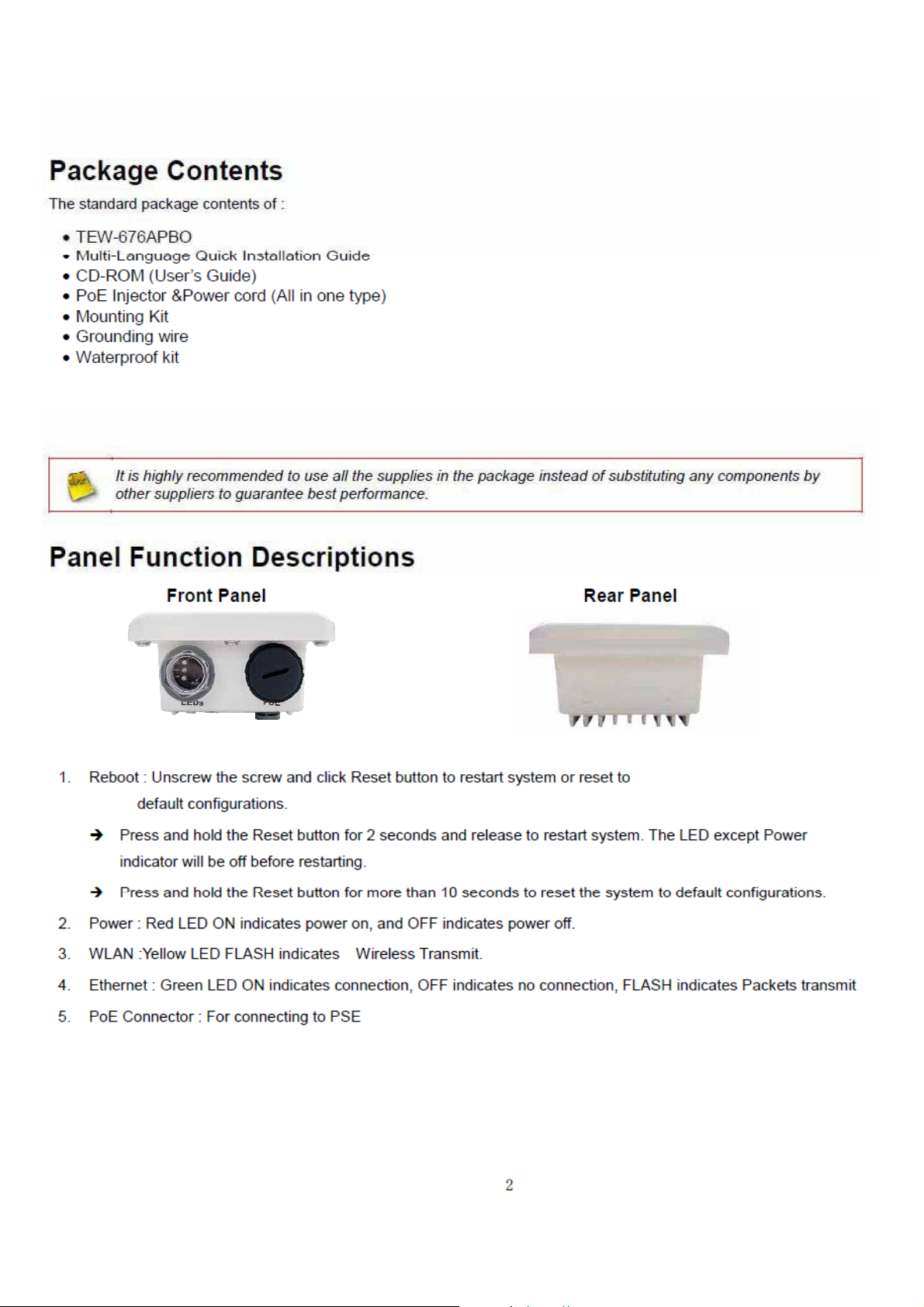
PACKAGE CONTENTS .................................................................................................................................................................................. 2
PANEL FUNCTION DESCRIPTIONS .................................................................................................................................................................. 2
SYSTEM CONCEPT ...................................................................................................................................................................................... 3
APPLICATIONS........................................................................................................................................................................................... 4
PRODUCT BENEFIT ..................................................................................................................................................................................... 8
INSTALLATION CONSIDERATIONS ................................................................................................................................................................... 8
WEB MANAGEMENT INTERFACE INSTRUCTIONS .............................................................................................................................................. 9
AP MODE CONFIGURATION ............................................................................................................................................................ 10
EXTERNAL NETWORK CONNECTION............................................................................................................................................................. 10
NETWORK REQUIREMENT ......................................................................................................................................................................... 10
Configure LAN IP ............................................................................................................................................................................ 11
WIRELESS LAN NETWORK ........................................................................................................................................................................ 13
Wireless General Setup .................................................................................................................................................................. 13
Wireless Advanced Setup ............................................................................................................................................................... 15
Create Virtual AP (VAP) ................................................................................................................................................................. 21
Wireless MAC Filter Setup ............................................................................................................................................................. 26
Wireless Network Expansion ......................................................................................................................................................... 26
SYSTEM MANAGEMENT ............................................................................................................................................................................ 28
Configure Management ................................................................................................................................................................ 28
Configure System Time .................................................................................................................................................................. 31
Configure SNMP Setup .................................................................................................................................................................. 32
Backup / Restore and Reset to Factory .......................................................................................................................................... 34
Firmware Upgrade ......................................................................................................................................................................... 35
Network Utility .............................................................................................................................................................................. 36
Reboot ........................................................................................................................................................................................... 37
SYSTEM STATU S....................................................................................................................................................................................... 38
System Overview ............................................................................................................................................................................ 38
Associated Clients Status ............................................................................................................................................................... 40
Show WDS Link Status ................................................................................................................................................................... 41
Extra Information .......................................................................................................................................................................... 42
Event Log ....................................................................................................................................................................................... 44
WDS MODE CONFIGURATION ......................................................................................................................................................... 44
EXTERNAL NETWORK CONNECTION............................................................................................................................................................. 45
Network Requirement ................................................................................................................................................................... 45
Configure LAN IP ............................................................................................................................................................................ 46
WIRELESS NETWORK EXPANSION ............................................................................................................................................................... 47
General Setup ................................................................................................................................................................................ 47
Wireless Advanced Setup ............................................................................................................................................................... 49
WDS Setup ..................................................................................................................................................................................... 55
SYSTEM MANAGEMENT ............................................................................................................................................................................ 56
Configure Management ................................................................................................................................................................ 56
Configure System Time .................................................................................................................................................................. 59
Configure SNMP Setup .................................................................................................................................................................. 60
Backup / Restore and Reset to Factory .......................................................................................................................................... 62
Firmware Upgrade ......................................................................................................................................................................... 63
Network Utility .............................................................................................................................................................................. 64
Reboot ........................................................................................................................................................................................... 65
SYSTEM STATU S....................................................................................................................................................................................... 66
System Overview ............................................................................................................................................................................ 66
WDS List ......................................................................................................................................................................................... 68
Extra Information .......................................................................................................................................................................... 69
Event Log ....................................................................................................................................................................................... 71
CPE MODE CONFIGURATION .......................................................................................................................................................... 71

EXTERNAL NETWORK CONNECTION............................................................................................................................................................. 72
Network Requirement ................................................................................................................................................................... 72
Configure WAN Setup .................................................................................................................................................................... 73
Configure DDNS Setup ................................................................................................................................................................... 76
Configure LAN Setup ...................................................................................................................................................................... 77
ACCESS POINT ASSOCIATION ...................................................................................................................................................................... 78
Configure Wireless General Setting ............................................................................................................................................... 78
Configure Wireless Advanced Setting ............................................................................................................................................ 80
Site Survey ..................................................................................................................................................................................... 81
Create Wireless Profile .................................................................................................................................................................. 82
SYSTEM MANAGEMENT ............................................................................................................................................................................ 84
Configure Management ................................................................................................................................................................ 84
Configure System Time .................................................................................................................................................................. 87
Configure UPnP .............................................................................................................................................................................. 88
Configure SNMP Setup .................................................................................................................................................................. 89
Backup / Restore and Reset to Factory .......................................................................................................................................... 91
Firmware Upgrade ......................................................................................................................................................................... 92
Network Utility .............................................................................................................................................................................. 93
Reboot ........................................................................................................................................................................................... 94
ACCESS CONTROL LIST .............................................................................................................................................................................. 95
IP Filter Setup ................................................................................................................................................................................ 95
MAC Filter Setup ............................................................................................................................................................................ 97
Parental Control Setup ................................................................................................................................................................... 98
QoS Setup .................................................................................................................................................................................... 100
RESOURCE SHARING .............................................................................................................................................................................. 103
DMZ ............................................................................................................................................................................................. 103
Virtual Server (Port Forwarding) ................................................................................................................................................. 104
SYSTEM STATU S..................................................................................................................................................................................... 106
Overview ...................................................................................................................................................................................... 106
Station Statistics .......................................................................................................................................................................... 109
Extra Info ..................................................................................................................................................................................... 111
QoS Plot ....................................................................................................................................................................................... 113
Event Log ..................................................................................................................................................................................... 114
CPE + AP MODE CONFIGURATION ................................................................................................................................................ 114
EXTERNAL NETWORK CONNECTION........................................................................................................................................................... 115
Network Requirement ................................................................................................................................................................. 115
Configure WAN Setup .................................................................................................................................................................. 116
Configure DDNS Setup ................................................................................................................................................................. 119
Configure LAN Setup .................................................................................................................................................................... 120
ACCESS POINT ASSOCIATION .................................................................................................................................................................... 121
Configure Wireless General Setting ............................................................................................................................................. 121
Wireless Advanced Setup ............................................................................................................................................................. 123
Site Survey ................................................................................................................................................................................... 129
Create Wireless Profile ................................................................................................................................................................ 130
WIRELESS LAN NETWORK CREATION ........................................................................................................................................................ 132
Repeater AP Setup ....................................................................................................................................................................... 132
Wireless MAC Filter Setup ........................................................................................................................................................... 136
SYSTEM MANAGEMENT .......................................................................................................................................................................... 137
Configure Management .............................................................................................................................................................. 137
Configure System Time ................................................................................................................................................................ 140
Configure UPnP ............................................................................................................................................................................ 141
Configure SNMP Setup ................................................................................................................................................................ 142
Backup / Restore and Reset to Factory ........................................................................................................................................ 144
Firmware Upgrade ....................................................................................................................................................................... 145
Network Utility ............................................................................................................................................................................ 146
Reboot ......................................................................................................................................................................................... 147
ACCESS CONTROL LIST ............................................................................................................................................................................ 148
IP Filter Setup .............................................................................................................................................................................. 148
MAC Filter Setup .......................................................................................................................................................................... 150
Parental Control Setup ................................................................................................................................................................. 151
QoS Setup .................................................................................................................................................................................... 153
RESOURCE SHARING .............................................................................................................................................................................. 156
DMZ ............................................................................................................................................................................................. 156

Virtual Server (Port Forwarding) ................................................................................................................................................. 157
SYSTEM STATU S..................................................................................................................................................................................... 159
Overview ...................................................................................................................................................................................... 159
Associated Clients Status ............................................................................................................................................................. 162
Remote AP ................................................................................................................................................................................... 163
Extra Info ..................................................................................................................................................................................... 164
QoS Plot ....................................................................................................................................................................................... 166
Event Log ..................................................................................................................................................................................... 167
CLIENT BRIDGE + UNIVERSAL REPEATER CONFIGURATION ............................................................................................................ 167
EXTERNAL NETWORK CONNECTION........................................................................................................................................................... 168
Network Requirement ................................................................................................................................................................. 168
Configure LAN IP .......................................................................................................................................................................... 169
ACCESS POINT ASSOCIATION .................................................................................................................................................................... 171
Configure Wireless General Setting ............................................................................................................................................. 171
Wireless Advanced Setup ............................................................................................................................................................. 173
Site Survey ................................................................................................................................................................................... 179
Create Wireless Profile ................................................................................................................................................................ 180
WIRELESS LAN NETWORK CREATION ........................................................................................................................................................ 182
Repeater AP Setup ....................................................................................................................................................................... 182
Wireless MAC Filter Setup ........................................................................................................................................................... 186
SYSTEM MANAGEMENT .......................................................................................................................................................................... 187
Configure Management .............................................................................................................................................................. 187
Configure System Time ................................................................................................................................................................ 190
Configure SNMP Setup ................................................................................................................................................................ 191
Backup / Restore and Reset to Factory ........................................................................................................................................ 193
Firmware Upgrade ....................................................................................................................................................................... 194
Network Utility ............................................................................................................................................................................ 195
Reboot ......................................................................................................................................................................................... 196
SYSTEM STATU S..................................................................................................................................................................................... 197
System Overview .......................................................................................................................................................................... 197
Associated Clients Status ............................................................................................................................................................. 200
Remote AP ................................................................................................................................................................................... 201
Extra Information ........................................................................................................................................................................ 202
Event Log ..................................................................................................................................................................................... 204
ROUTER AP MODE CONFIGURATION ............................................................................................................................................ 204
EXTERNAL NETWORK CONNECTION........................................................................................................................................................... 205
Network Requirement ................................................................................................................................................................. 205
Configure WAN Setup .................................................................................................................................................................. 206
Configure DDNS Setup ................................................................................................................................................................. 209
Configure LAN Setup .................................................................................................................................................................... 210
WIRELESS LAN NETWORK CREATION ........................................................................................................................................................ 211
Wireless General Setup ................................................................................................................................................................ 211
Wireless Advanced Setup ............................................................................................................................................................. 213
Create Virtual AP (VAP) ............................................................................................................................................................... 219
Wireless MAC Filter Setup ........................................................................................................................................................... 224
WIRELESS NETWORK EXPANSION ............................................................................................................................................................. 225
SYSTEM MANAGEMENT .......................................................................................................................................................................... 226
Configure Management .............................................................................................................................................................. 226
Configure System Time ................................................................................................................................................................ 229
Configure UPnP ............................................................................................................................................................................ 230
Configure SNMP Setup ................................................................................................................................................................ 231
Backup / Restore and Reset to Factory ........................................................................................................................................ 233
Firmware Upgrade ....................................................................................................................................................................... 234
Network Utility ............................................................................................................................................................................ 235
Reboot ......................................................................................................................................................................................... 236
ACCESS CONTROL LIST ............................................................................................................................................................................ 236
IP Filter Setup .............................................................................................................................................................................. 236
MAC Filter Setup .......................................................................................................................................................................... 238
Parental Control Setup ................................................................................................................................................................. 239
QoS Setup .................................................................................................................................................................................... 241
RESOURCE SHARING .............................................................................................................................................................................. 244
DMZ ............................................................................................................................................................................................. 244

Virtual Server (Port Forwarding) ................................................................................................................................................. 245
SYSTEM STATU S..................................................................................................................................................................................... 246
Overview ...................................................................................................................................................................................... 246
Associated Clients ........................................................................................................................................................................ 249
Show WDS Link ............................................................................................................................................................................ 250
Extra Info ..................................................................................................................................................................................... 251
QoS Plot ....................................................................................................................................................................................... 253
Event Log ..................................................................................................................................................................................... 253
APPENDIX ..................................................................................................................................................................................... 254
WINDOWS TCP/IP SETTINGS .................................................................................................................................................................. 254
WEB GUI VALID CHARACTERS ................................................................................................................................................................ 256
MCS DATA RATE ................................................................................................................................................................................... 259
SYSTEM MANAGER PRIVILEGES ................................................................................................................................................................ 259
ENABLING UPNP IN WINDOWS XP ........................................................................................................................................................... 261
SPECIFICATION ...................................................................................................................................................................................... 263
LIMITED WARRANTY .............................................................................................................................................................................. 264
.

FCC Regulatory Information
This equipment has been tested and found to comply with the limits for a class B digital
device,pursuant to part 15 of the FCC Rules. These limits are designed to provide reasonable
protection against harmful interference in a residential installation. This equipment generates, uses
and can radiate radio frequency energy and, if not installed and used in accordance with the
instructions, may cause harmful interference to radio communications. However, there is no
guarantee that interference will not occur in a particular installation. If this equipment does cause
harmful interference to radio or television reception,which can be determined by turning the
equipment off and on, the user is encouraged to try to correct the interference by one or more of the
following measures:
---Reorient or relocate the receiving antenna.
---Increase the separation between the equipment and receiver.
---Connect the equipment into an outlet on a circuit different from that to which the receiver is
connected.
---Consult the dealer or an experienced radio/TV technician for help.
This device is restricted to INDOOR USE due to its operation in the 5.15 to 5.25GHz frequency range.
According to FCC 15.407(e), requires this product to be used indoors for the frequency range 5.15 to
5.25GHz to reduce the potential for harmful interference to co-channel of the Mobile Satellite
Systems. High power radars are allocated as primary user of the 5.25 to 5.35GHz and 5.65 to
5.85GHz bands. These radar stations can cause interference with and / or damage this device You
are cautioned that changes or modifications not expressly approved by the party responsible for
compliance could void your authority to operate the equipment. This device complies with part 15 of
the FCC rules. Operation is subject to the following two conditions
(1) This device may not cause harmful interference and
(2) This device must accept any interference received, including interference that may cause
undesired operation
FCC RF radiation exposure statement:
1.this transmitter must not be co-located or operating in conjunction with any other antenna or
transmitter .
2.this equipment complies with FCC RF radiation exposure limits ser forth for an uncontrolled
environment. This equipment should be installed and operated with a minimum distance of 20
centimeters between the radiator and your body .

Introduction
12dBi
The 14dBi High Power Wireless N Outdoor PoE Access Point, model TEW-676APBO, provides high speed
point-to-point building connectivity. It supports a variety of installation scenarios with Access Point, Router
Access Point, Wireless Distribution System (WDS), Customer Premises Equipment (CPE), and Repeater
modes.
An IP-66/67 weather rating and rugged aluminum housing ensures the highest level of protection against
extreme weather. An outdoor mounting kit is included and weatherproof LED indicators expedite product
installation a
No need to install this access point near a power source—PoE technology transmits both power and data
over an Ethernet cable. Support for the latest wireless security protocols ensures the highest level of network
protection. Install this access point with TRENDnet’s Outdoor Lightning Arrestor Kit, model TEW-ASAL1, to
protect your entire network from catastrophic lightning strikes.
Features
x PoE compliant device
x 1 x 10/100Mbps PoE Auto-MDIX LAN port
x 1 x reset button
x LED indicators: Power, WLAN, LAN, Internal high powered 14dBi patch antenna (polarization: V30q, H30q)
x Compliant with 802.11n/a technology (5 GHz spectrum) with data rates up to 300Mbps
x Rugged IP66/67 rated weather proof aluminum housing
x Supports Router Access Point (AP), Access Point (AP), Wireless Distribution System (WDS), Customer
Premises Equipment (CPE), Client Brid
x Multiple SSID or Virtual Access Points with Layer 2 VLAN client isolation
x Access restriction with Internet Access Control, MAC, and IP filtering
x Universal Plug and Play (UPnP) for auto discovery and support for device configuration of Internet
applications
x Complete wireless security with WPA/WPA2-RADIUS, WPA /WPA2-PSK, and WEP
x Multiple pass-through sessions for popular VPN applications (IPSec, L
x Quality of Service technology: IEEE 802.11p COS, IEEE 802.11q Tag VLAN priority control and Wi-Fi
Multimedia (WMM)
x Supports IEEE 802.11f IAPP (Inter Access Point Protocol), IEEE 802.11h (Transmission Power Control)
and IEEE 802.11d (Multi-country roaming)
x Easy setup via Web browser using the latest versions of Internet Explorer, FireFox, and Safari
x Supports SNMP (v2c and v3), Telnet, SSH, and HTTP/HTTPS management
x Surface m
x Electrical ground cable
x 3-year limited warranty
nd troubleshooting.
ge + Repeater, and CPE + AP modes
2TP, and PPTP)
ounting hardware
㻝
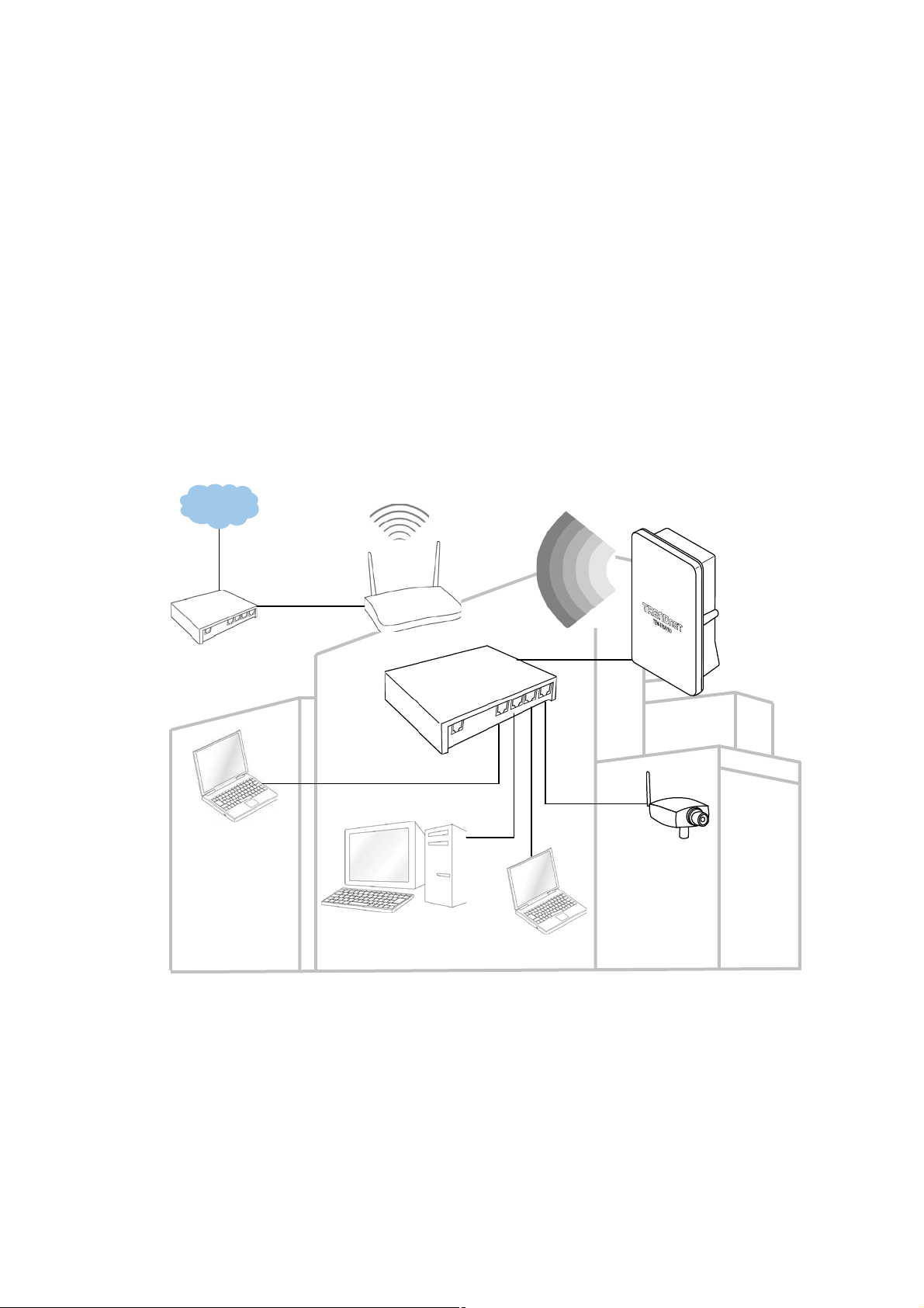
System Concept
oteboo
The TEW-676APBO is not only designed and used as a traditional outdoor AP, but also with rich features tailored for
WISP applications. The two-level management capability and access control ease WISP and owners to maintain and
manage wireless network in a more controllable fashion. Main applications are listed as follows with illustration:
Wireless CPE for Multi Dwelling Unit/Multi Tenant Unit(MDU/MTU) complexes including apartments, dormitories, and
office complexes.
Outdoor Access Point for school campuses, enterprise campuses, or manufacture plants.
Indoor Access Point for hotels, factories, or warehouses where industrial grade devices are preferred.
Public hotspot operation for café, parks, convention centers, shopping malls, or airports.
Wireless coverage for indoor and outdoor grounds in private resorts, home yards, or gulf course communities.
Internet
N
Router
k
WAN
WISP
AP
LAN
TEW-676APBO
PoE
Surveillance
DMZ
Online Game
㻟

Applications
TEW-676APBO is multiple mode system which can be configured either as a wireless gateway or an access point as
desired. It also can be used as a WDS link for Ethernet network expansion. This section depicts different applications on
Router AP Mode, AP Mode, WDS Mode, CPE Mode, Client Bridge + Universal Repeater Mode and CPE + AP Mode.
Configuration on Router AP Mode (Gateway + Access Point + WDS)
Î Example 1 : Router AP without WDS
9 It can be deployed as a gateway with wireless Access Point
NAT
Internet
WAN
192.168.1.254
TEW-676APBO
Î Example 2 : Router AP with WDS
9 It can be deployed as a gateway with wireless Access Point and provides WDS link for network extension.
NAT
SSID: Main_AP
192.168.2.10
WLAN
192.168.2.254
Remote Bass Station
192.168.2.x
WDS
Internet
WAN
192.168.1.254
TEW-676APBO
㻠
WLAN
192.168.2.254
SSID: Main_AP
192.168.2.10
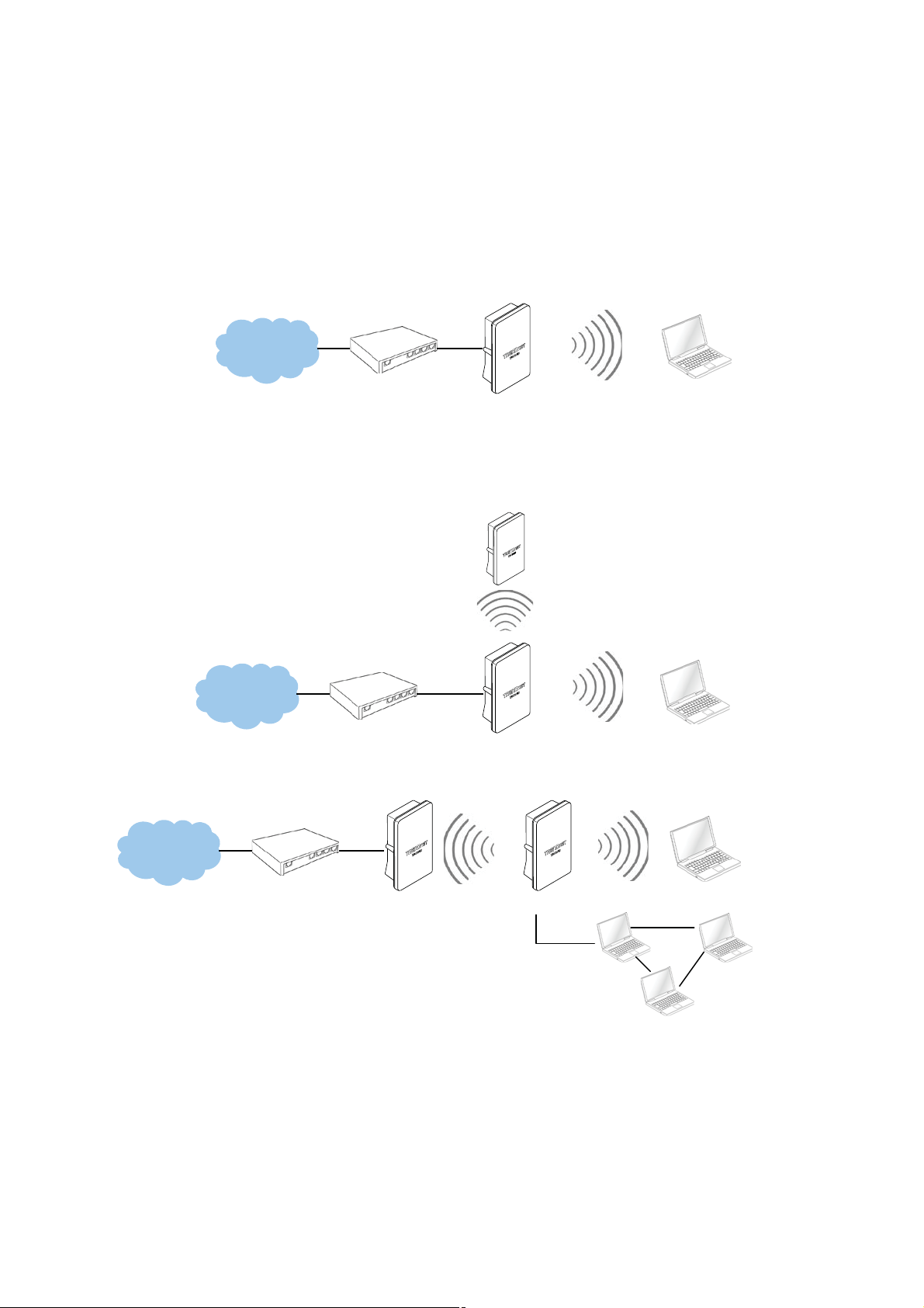
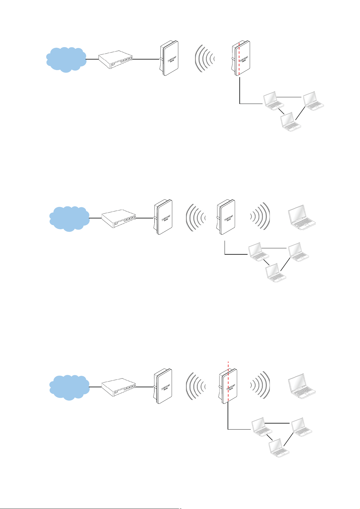
Configuration in AP Mode (including Access Point + WDS)
_
_
An access point can be either a main, relay or remote base station. A main base station is typically connected to a
wired network via the Ethernet port. A relay base station relays data between main base stations and relay stations or
remote base stations with clients. A remote base station is the end point to accept connections from wireless clients
and pass data upwards to a network wirelessly.
Î Example 1 : Access Point without WDS
9 It can be deployed as a tradition fixed wireless Access Point
SSID: Main
Internet
192.168.2.254
TEW-676APBO
Î Example 2 : Access Point with WDS
9 It can be deployed as a tradition fixed wireless Access Point and provides WDS link to expand network
Remote Bass Station
192.168.2.250
WDS
SSID: Main_AP
Internet
192.168.2.254
TEW-676APBO
AP
192.168.2.10
192.168.2.10
AP
192.168.2.10
192.168.2.x
Internet
Main Base Station
192.168.2.250
Configuration in WDS Mode (Pure WDS)
WDS
TEW-676APBO
SSID: Main
192.168.2.254
An access point can be either a main, relay or remote base station. A main base station is typically connected to a
wired network via the Ethernet port. A relay base station relays data between main base stations and relay stations or
remote base stations with clients. A remote base station is the end point to accept connections from wireless clients
and pass data upwards to a network wirelessly. In this mode, it ca
n support single or multiple WDS links and no
wireless clients can associate with it.
㻡

Î Example 1 : Point-to-Point
WDS
Internet
Internet
Î Example 2 : Point-to-Multi-Point
192.168.2.254
TEW-676APBO
Main Base Station
192.168.2.250
WDS
Remote Base Station
Remote Bass Station
192.168.2.250
TEW-676APBO
WDS
192.168.2.254
192.168.2.x
192.168.2.x
WDS
WDS
Remote Base Station
192.168.2.251
WDS
Remote Base Station
192.168.2.252
192.168.2.254
TEW-676APBO
192.168.2.x
192.168.2.x
WDS
Remote Base Station
192.168.2.253
Internet
192.168.2.254
TEW-676APBO
Î Example 3 : Multi-Point Repeating bridge
Internet
Main Base Station
192.168.2.250
Configuration in CPE Mode
It can be used as an Outdoor Customer Premises Equipment (CPE) to receive wireless signal over last mile
application, helping WISPs deliver wireless broadband Internet service to residents and business customers. In the
CPE mode, TEW-676APBO is a gateway enabled with NAT and DHCP Server functions. The wired clients connected
to TEW-676APBO are in different subnet from those connected to Main Base Station, and, in CPE mode, it does not
accept wireless association from wireless clients.
㻢
_
_
Internet
SSID: Main_AP
NAT
Main Base Station
192.168.1.150
Configuration in Client Bridge + Universal Repeater Mode
WIFI WAN
192.168.1.254
TEW-676APBO
LAN
192.168.2.254
192.168.2.x
It can be used as an Client Bridge + Universal Repeater to receive wireless signal over last mile applications, helping
WISPs deliver wireless broadband Internet service to new residential and business customers. In this mode, TEW-
676APBO is enabled with DHCP Server functions. The wired clients of WCB1200H2PX are in the same subnet from
Main Base Station and it accepts wireless connections from client devices.
SSID: Main
Internet
Main Base Station
192.168.2.250
AP SSID: Repeater_Main_AP
192.168.2.254
TEW-676APBO
192.168.2.10
192.168.2.x
Configuration on CPE + AP Mode (Router Client + Access Point)
It can be used as an Outdoor Customer Premised Equipment(CPE) to receive wireless signal over the last mile,
helping WISPs deliver wireless broadband Internet service to new residential and business customers. In this mode,
theTEW-676APBO is a gateway with NAT and DHCP Server functions. The wireless and wired clients of TEW-
676APBO are on the different subnet from Main Base Station and it accepts wireless connections from client
devices.
NAT
SSID: Main
Internet
Main Base Station
192.168.2.250
AP SSID: Repeater_Main_AP
WIFI WAN
192.168.1.254
TEW-676APBO
LAN
192.168.2.254
192.168.2.x
㻣

Product Benefit
The 14dBi High Power Wireless N Outdoor PoE Access Point is the point of connection to Wireless Outdoor Network for
service provider deploying last mile services to business or residential broadband subscribers.. Network administrators
can create multiple subscriber service tier using per-subscriber rate limiting features, and manage centrally.
WCB1200H2PX outdoor bridge utilizes a 200mW output Tx Power to connect to the WiFi mesh or WDS infrastructure and
provides the subscriber with an Ethernet connection for a local access.
The 14dBi Hig
modes, the Router AP mode , AP mode, the WDS mode, the CPE mode, Client Bridge + Universal Repeater mode and
CPE + AP mode,
h Power Wireless N Outdoor PoE Access Point can be used for nine different purposes in six different
Installation Considerations
There are a number of factors that can impact the range of wireless devices.
1. Adjust your wireless devices so that the signal is traveling in a straight path, rather than at an ang le. The more
material the signal has to pass through the more signal you will lose.
2. Keep the number of obstructions to a minimum. Ea
Position the wireless devices in a manner that will minimize the amount of obstructions between them.
3. Building materials can have a large impact on your wireless signal. In an indoor environment, try to position the
wireless devices so that the signal passes through less dense material such as dry wall. Dense materials like metal,
solid wood, g
lass or even furniture may block or degrade the signal.
ch obstruction can reduce the range of a wireless device.
4. Antenna orientation can also have a large impact on your wireless signal. Use the wireless adapter’s site survey tool
to determine the best antenna orientation for your wireless devices.
5. Interference from devices that produce RF (radio frequency) noise can also impact your signal. Position your wireless
devices away from anything th
6. Any device operating on the 2.4GHz frequency will cause interference. Devices such as 2.4GHz cordless phones or
other wireless remotes operating on the 2.4GHz frequency can potentially drop the wireless signal. Although the
phone may not be in use, the base can still transmit wireless signal. Move the phone’s base station as far away
possible from your wireless devices.
If you are still experiencing low or no signal consider repositioning the wireless devices or installing additional access
points. The use of higher gain antennas may also provide the necessary coverage depending on the environment.
at generates RF noise, such as microwaves, radios and baby monitors.
as
㻤

Web Management Interface Instructions
TEW-676APBO supports web-based configuration. Upon the completion of hardware installation, WCB1200H2PX can be
configured through a PC/NB by using its web browser such as Internet Explorer version 6.0.
Default IP Address : 192.168.2.254
Default IP Netmask : 255.255.255.0
Default User Name and Password :
The default user name and password for both root manager account and admin manager account are as follows :
Mode Router AP CPE AP WDS UR + CB CPE + AP
Management Account
User Name
Password
Root
Account
root root admin root root root root admin
default default admin defa
Root
Account
Admin
Account
Root
Account
Root
Account
ult default default default admin
Root
Account
Root
Account
Step
IP Segment Set-up for Administrator's PC/NB
Set the IP segment of the administrator's computer to be in the same range as TEW-676APBO for accessing the
system. Do not duplicate the IP Address used here with IP Address of TEW-676APBO or any other device within the
network
Example of Segment :
The valid range is 1 ~ 254 and 192.168.2.254 shall be avoided because it is already assigned to TEW-676APBO .
192.168.2.10 is used in the example below.
IP Address : 192.168.2.10
Admin
Account
IP Netmask : 255.255.255.0
Launch Web Browser
Launch web browser to access the web management interface of system by entering the default IP Address,
http://192.168.2.254
System Login
The system manager Login Page then appears.
Enter “root” as User name and “root” as Password, and then click OK to login to the system; the root manager
account is used as an example here.
Login Success
System Overview page will appear after successful login.
, in the URL field, and then press Enter.
㻥
AP Mode Configuration
_
When AP mode is chosen, the system can be configured as an Access Point. This section provides detailed explanation
for users to configure in the AP mode with help of illustrations. In the AP mode, functions listed in the table below are also
available from the Web-based GUI interface.
Option System Wireless Utilities Status
Operating Mode General Setup Profiles Settings System Overview
LAN Advanced Setup Firmware Upgrade Clients
Functions
Management Virtual AP Network Utility WDS Status
Time Server WDS Setup Reboot Extra Info
SNMP Event Log
Table 3-1: AP Mode Functions
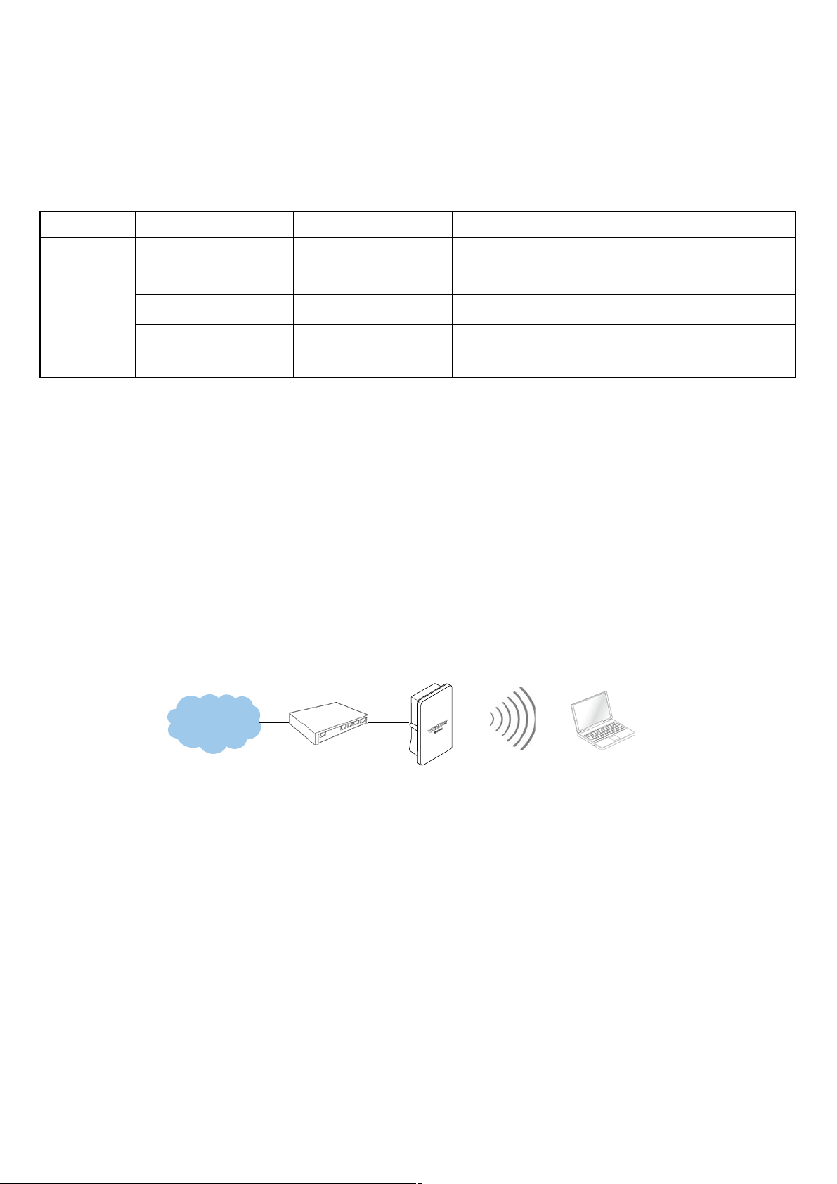
External Network Connection
Network Requirement
Normally, TEW-676APBO connects to a wired LAN and provides a wireless connection point to associate with wireless
client as shown in Figure 3-1. Then, Wireless clients could access to LAN or Internet by associating themselves with
TEW-676APBO set in AP mode.
SSID: Main
AP
Internet
192.168.2.10
192.168.2.254
TEW-676APBO
Figure 3-1 Access Point on a Wired LAN Configuration
㻝㻜
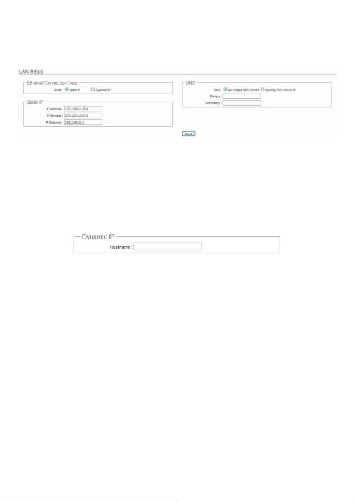
Configure LAN IP
Here are the instructions to setup the local IP Address and Netmask.
Please click on System -> LAN and follow the below setting.
Mode : Check either “Static IP” or “Dynamic IP” button as desired to set up the system IP of LAN port .
Î Static IP : The administrator can manually setup the LAN IP address when static IP is available/ preferred.
9 IP Address : The IP address of the LAN port; default IP address is 192.168.2.254
9 IP Netmask : The Subnet mask of the LAN port; default Netmask is 255.255.255.0
9 IP Gateway : The default gateway of the LAN port; default Gateway is 192.168.2.1
Î Dynamic IP : This configuration type is applicable when the TEW-676APBO is connected to a network with the
presence of a DHCP server; all related IP information will be provided by the DHCP server automatically.
9 Hostname : The Hostname of the LAN port
DNS : Check either “No Default DNS Server” or “Specify DNS Server IP” button as desired to set up the system
DNS.
Î Primary : The IP address of the primary DNS server.
Î Secondary : The IP address of the secondary DNS server.
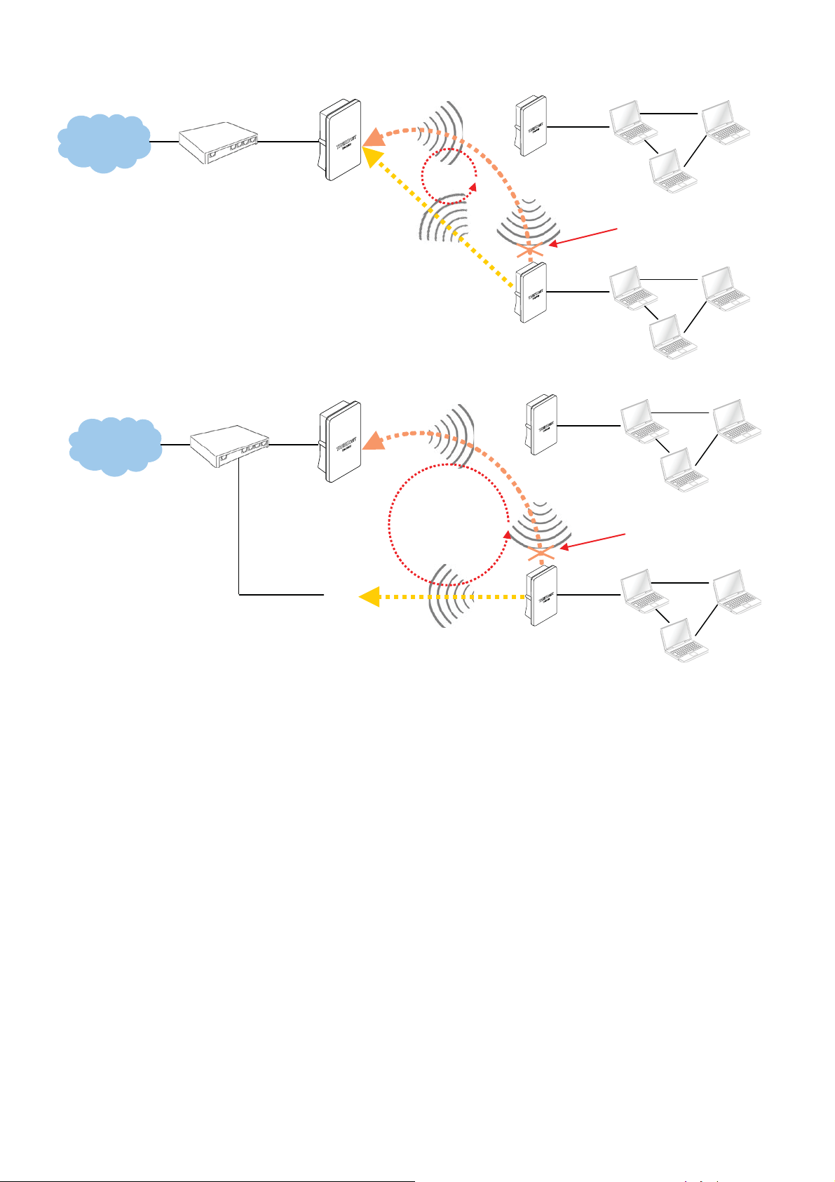
802.1d Spanning Tree
The spanning tree network protocol provides a loop free topology for a bridged LAN between LAN interface and 4
WDS interfaces from wds0 to wds3. The Spanning Tree Protocol, which is also referred to as STP, is defined in the
IEEE Standard 802.1d. The Spanning tree always enabled on TEW-676APBO. Below Figures depict a loop for a
bridged LAN between LAN and WDS link
㻝㻝
Internet
Internet
192.168.2.254
TEW-676APBO
192.168.2.254
TEW-676APBO
WDS
WDS
LOOP
WDS
LOOP
Remote Base Station
192.168.2.250
WDS
Remote Base Station
192.168.2.251
Remote Base Station
192.168.2.250
WDS
192.168.2.x
Ńlocked by
Spanning Tree Protocol
192.168.2.x
192.168.2.x
Ńlocked by
Spanning Tree Protocol
Base Station
192.168.2.253
WDS
Remote Base Station
192.168.2.251
Click Save button to save your changes. Click Reboot button to activate your changes
192.168.2.x
㻝㻞
Wireless LAN Network
The network manager can configure related wireless settings, General Settings, Advanced Settings, Virtual AP(VAP)
Setting, Security Settings and MAC Filter Settings.
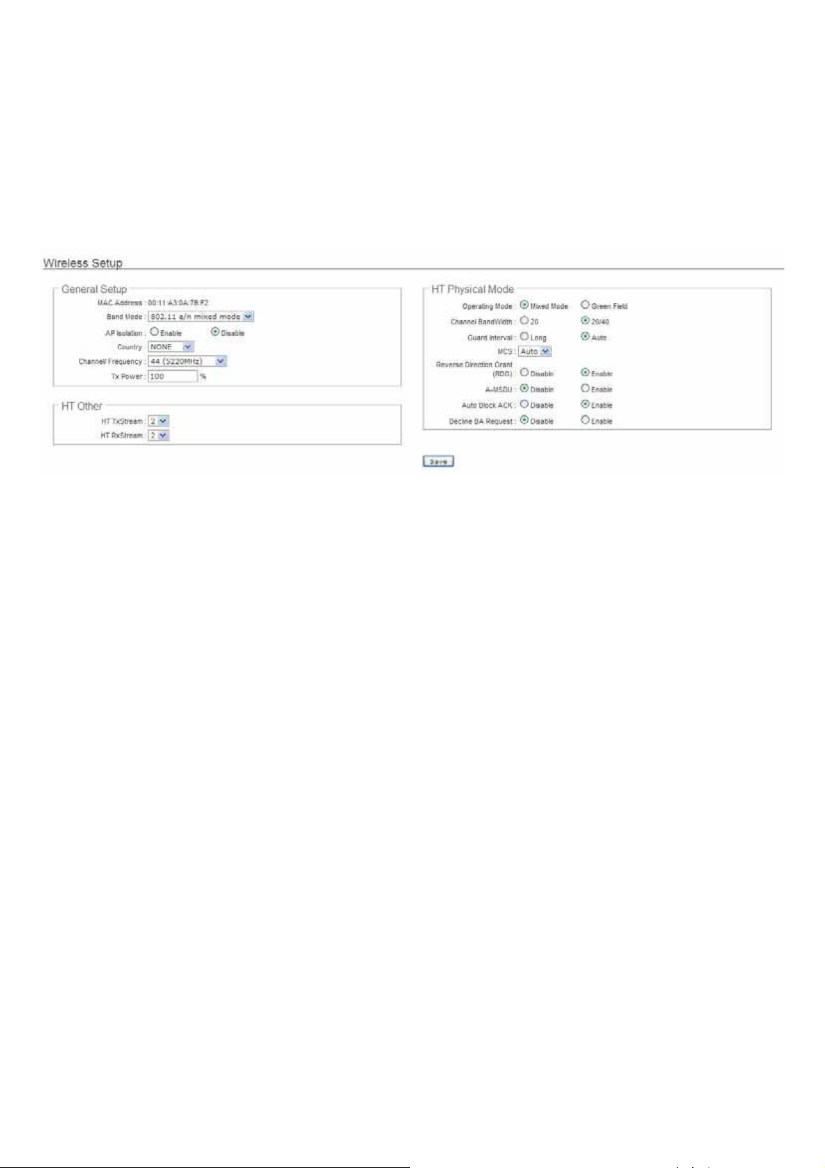
Wireless General Setup
The administrator can change the data transmission, channel and output power settings for the system. Please click on
Wireless -> General Setup and follow the below setting.
MAC Address : The MAC address of the Wireless interface is displayed here.
Band Mode : Select an appropriate wireless band; bands available are 801.11a or 802.11a/n mixed mode.
AP Isolation : Select Enable, all clients will be isolated from each VAP, that means different VAP's clients can not
reach to each other.
Transmit Rate Control : Select the desired rate from the drop-down list; the options are auto or ranging from 6 to
54Mbps only for 802.11a mode.
Country : Select the desired country code from the drop-down list; the options are US, ETSI, JP and NONE.
Channel/Frequency : The channel range will be changed by selecting different country code. Below depicts the
channel range for different Country. When “Band Mode” selected in “802.11a/n”, the Channel 140 and 165 does not
shown-up on list.
Country Channel
US 36, 40, 44, 48, 52, 56, 60, 64, 149, 153, 157, 161, 165
ETSI 36, 40, 44, 48, 52, 56, 60, 64, 100, 104, 108, 112, 116, 120, 124, 128, 132, 136, 140
JP 36, 40, 44, 48
NONE 36, 40, 44, 48, 52, 56, 60, 64, 100, 104, 108, 112, 116, 120, 124, 128, 132, 136, 140, 149, 153, 157, 161, 165
Tx Power : You can adjust the output power of the system to get the appropriate coverage for your wireless network.
Specify digit numbers between 1 to 100 (the unit is %) for your environment. If you are not sure which setting to
choose, then keep the default setting, 100%.
When Band Mode select in 802.11a only mode, the HT(High Throughput) settings should be hidden immediately.
㻝㻟

HT TxStream/RxStream : By default, it's 2.
Operating Mode : By default, it's Mixed Mode.
Î Mixed Mode : In this mode packets are transmitted with a preamble compatible with the legacy 802.11a/g, the
rest of the packet has a new format. In this mode the receiver shall be able to decode both the Mixed Mode
packets and legacy packets.
Î Green Field : In this mode high throughput packets are transmitted without a legacy compatible part.
Channel Bandwidth : The "20/40” MHz option is usually best. The other option is available for special
circumstances.
Guard Interval : Using “Auto” option can increase throughput. However, it can also increase error rate in some
installations, due to increased sensitivity to radio-frequency reflections. Select the option that works best for your
installation.
MCS : This parameter represents transmission rate. By default (Auto) the fastest possible transmission rate will be
selected. You have the option of selecting the speed if necessary. (Refer to Appendix C. MCS Data Rate)
Reverse Direction Grant(RDG) : Disable or enable reserve direction grant. Default is enabled.
A-MSDU : Aggregated Mac Service Data Unit. Select Enable to allow aggregation for multiple MSDUs in one MPDU
Default is disabled.
Auto Block ACK : Disable or enable auto block ACK. Default is enabled.
Decline BA Request : Disable or enable decline BA request. Default is disabled.
Change these settings as described here and click Save button to save your changes. Click Reboot button to activate
your changes. The items in this page are for AP's RF general settings and will be applied to all VAPs and WDS Links.
㻝㻠

Wireless Advanced Setup
To achieve optimal wireless performance, it is necessary to tweak advance setting per requirements properly, not
necessary higher the better or lower.
The administrator can change the RTS threshold and fragmentation threshold settings for the system. Please click on
Wireless -> Advanced Setup and follow the below setting.
Short Slot : By default, it’s “Enable” for educing the slot time from the standard 20 microseconds to the 9
microsecond short slot time
Slot time is the amount of time a device waits after a collision before retransmitting a packet. Reducing the slot time
decreases the overall back-off, which increases throughput. Back-off, which is a multiple of the slot time, is the
random length of tim
channel the shorter slot time help manage shorter wait time to re-transmit f rom collision because of hidden wireless
clients or other causes. When collision sources can be removed sooner and other senders attempting to send are
listening the channel(CSMA/CA) the owner of the channel should continue ownership and finish their transmission
and release the channel. Then, follow
time. However, when long duration of existing collision sources and shorter slot time exist the owners might
experience subsequent collisions. When adj ustment to longer slot time can’t improve performance then RTS/CTS
could supplement and help improve performance.
Extra Slot Time : Slot time is in the range of 1~255 and set in unit of microsecond. The default value is 9
microsecond.
When you enable Short Slot and set Extra Slot time to “10”, the actual Slot Time=9+10 us.
When you disable Short Slot and set Extra Slot time to “10”, the actual Slot Time=20+10 us.
e a station waits before sending a packet on the LAN. For a sender and receiver own right of the
ing ownership of the channel will be sooner for the new pair due to shorter slot
㻝㻡

ACK Timeout : ACK timeout is in the range of 1~255 and set in unit of microsecond. The default value is 32
microsecond.
All data transmission in 802.11b/g request an “Acknowledgement” (ACK) send by receiving radio. The transmitter will
resend the original packet if correspondent ACK failed to arrive within specific time interval, also refer to as “ACK
Timeout”.
ACK Timeout is adjustable due to the fact tha
t distance between two radio links may vary in different deployment.
ACK Timeout makes significant influence in performance of long distance radio link. If ACK Timeout is set too short,
transmitter will start to “Resend” packet before ACK is received, and throughputs become low due to excessively high
re-transmission.
ACK Timeout is best determined by distance between the radios, data rate of average environment. The Timeout
value is calculated based on round-trip time of packet with a little tolerance, So, if experiencing re-transmissions or
poor performance the ACK Timeout could be made longer to accommodate.
Slot Time and ACK Timeout settings are for long distance links. It is important to tweak settings to achieve the
optimal result based on requirement.
Beacon Interval : Beacon Interval is in the range of 20~1024 and set in unit of millisecond. The default value is 100
msec.
Access Point (AP) in IEEE 802.11 will send out a special approximated 50-byte frame, called “Beacon”. Beacon is
broadcast to all the stations, provides the basic information of AP such as SSID, channel, encryption keys, signal
strength, time stamp, support data rate.
All the radio stations received bea
con recognizes the existence of such AP, and may proceed next actions if the
information from AP matches the requirement. Beacon is sent on a periodic basis, the time interval can be adjusted.
By increasing the beacon interval, you can reduce the number of beacons and associated overhead, but that will
likely delay the association and roaming process beca use stations scanning for ava
ilable access points may miss the
beacons. You can decrease the beacon interval, which increases the rate of beacons. This will make the association
and roaming process very responsive; however, the network will incur additional overhead and throughput will go
down.
DTIM Interval : The DTIM interval is in the range of 1~255. The default is 1.
DTIM is defined as Delivery Traffic Indication Message. It is used to notify the wireless stations, which support power
saving mode, when to wake up to receive multicast frame. DTIM is necessary and critical in wireless environment as
a mechanism to fulfill power-saving synchronization.
A DTIM interval is a count of the number of beacon
frames that must occur before the access point sends the
buffered multicast frames. For instance, if DTIM Interval is set to 3, then the Wi-Fi clients will expect to receive a
multicast frame after receiving three Beacon frame. The higher DTIM interval will help power saving and possibly
decrease wireless throughput in multicast applications.
㻝㻢

Fragment Threshold : The Fragment Threshold is in the range of 256~2346 byte. The default is 2346 byte.
Each Wi-Fi packet can be divided into smaller packets, marked with a sequential f ragment number and re-assemble
in the receiving ends. The purpose is to make a short frame, instead of long frame, transmitting by radio in a heavy
noisy environment. Because of sending smaller fr
obvious, the cons is the overhead for transmission. So, in a clean environment, higher fragment threshold can be an
option to increase throughput.
Fragmentation will be triggered by setting the Fragment Threshold, usually in Byte-length. Only when the frame size
is over the Threshold, fragmentation will take place automatically.
RTS Threshold : TRTS Threshold is in the range of 1~2347 byte. The default is 2347 byte.
The main purpose of enabling RTS by changing RTS threshold is to reduce possible collisions due to hidden wireless
clients. RTS in AP will be enabled automatically if the packet size is larger than the Threshold value. By default, RTS
is disabled in a normal environment supports non-jumbo frames.
Short Preamble : By default, it’s “Enable”. To Disable is to use Long 128-bit Preamble Synchronization field.
The preamble is used to signal "here is a train of data coming" to the receiver. The short preamble provides 72-bit
Synchronization field to improve WLAN transmission efficiency with less overhead.
Tx Burst : By default, it’s “Enable”. To Disable is to deactivate Tx Burst.
With TX burst enabled, AP will send many packets in a burst, without collision detection and RTS/CTS for each packet. TX
Burst have better throughput but cause interference with other APs in channel.
Pkt_Aggregate : By default, it's “Enable”
ames, corruptions are much less likely to occur. The pros is
Increase efficiency by aggregating multiple packets of application data into a single transmission frame. In this way,
802.11n networks can send multiple data packets with the fixed overhead cost of just a single frame.
IEEE802.11H (DFS) : By default, it's “Disable”. To Enable is to use IEEE802.11H(DFS)
With DFS(Dynamic Frequency Selection) enabled, radio is operating on one of the following channels, the wireless
device uses DFS to monitor the operating frequency and switch to another frequency or reduce power as necessary:
DFS Channels
The maximum legal transmit power is gre
randomly selects a 5 GHz channel on which power is restricted, the wireless device automatically reduces transmit
power to comply with power limits for that channel in that regulatory domain.
52, 56, 60, 64, 100, 104, 108, 112, 116, 120, 124, 128, 136, 140
ater for some 5 GHz channels than for others. When the wireless device
The Channel 52-140 is DFS channel. If tuen on IEEE802.11H, AP Will have 60 sec to do
channel available check, and will not send beacon and can not be connect. When
WCB1200H2PX detect radar(5GHz) signal, the AP will switch channel and stop beacon
trasmit between 15 sec.
㻝㻣
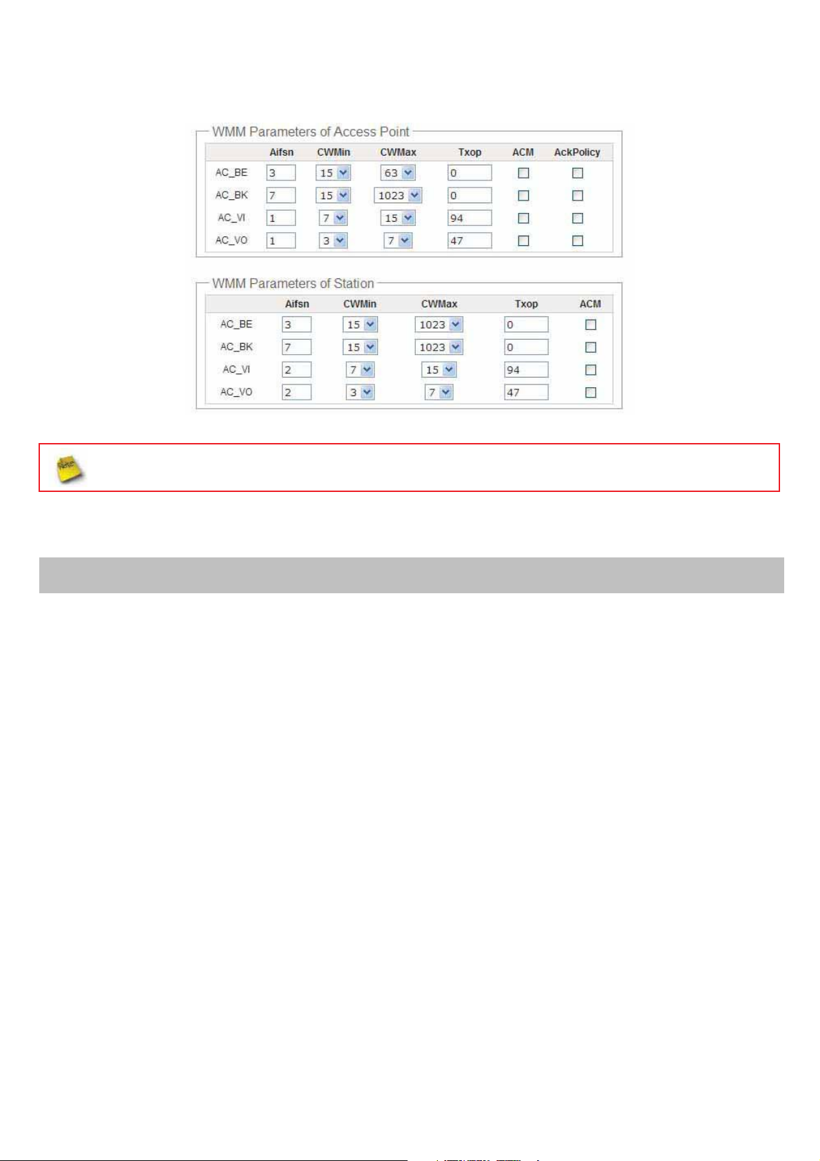
WMM : By default, it's “Disable”. To Enable is to use WMM and the WMM parameters should appears.
When you enable WMM, the “Tx Burst” will be Disabled automatically by system.
Î WMM Parameters of Access Point : This affects traffic flowing from the access point to the client station
Queue
AC_BK Background. Low
Data Transmitted
AP to Clients
Priority Description
High throughput. Bulk data that requires maximum throughput and is not timesensitive is sent to this queue (FTP data, for example).
AC_BE Best Effort Medium Medium throughput and delay. Most traditional IP data is sent to this queue
AC_VI Video High Minim um delay. Time-sensitive video data is automatically sent to this queue
Tim
AC_VO Voice High
e-sensitive data like VoIP and streaming media are automatically sent to this
queue
Configuring QoS options consists of setting parameters on existing queues for different types of wireless traffic.
You can configure different minimum and maximum wait times for the transmission of packets in each queue
ased on the requirements of the media being sent. Queues automatically provide minimum transmission delay
b
for Voice, Video, multimedia, and mission critical applications, and rely on best-effort parameters for traditional IP
data.
As an Example, time-sensitive Voice & Video, and multimedia are given effectively higher priority f
or transmission
(lower wait times for channel access), while other applications and traditional IP data which are less time-
sensitive but often more data-intensive are expected to tolerate longer wait times.
㻝㻤

9 Aifsn : The Arbitration Inter-Frame Spacing Number specif ies a wait time (in milliseconds) for data frames
9 CWmin : Minimum Contention Window. This parameter is input to the a lgorithm that determines the initial
random back-off wait time ("window") f or retry of a transmission. The value specified here in the Minimum
Contention Window is the upper limit (in milliseconds) of a range from which the initial random back-off wait
time is determined.
9 CWmax : Maximum Contention Window. The value specified here in the Maximum Contention Window is
the upper limit (in milliseconds) for the doubling of the random back-off value. This doubling continues until
either the data frame is sent or the Maximum Contention Window size is reached. Once the Maximum
Contention Window size is reached, retries will continue until a maximum number of retries allowed is
ched. Valid values for the "cwmax" are 1, 3, 7, 15, 31, 63, 127, 255, 511, or 1024. The value for "cwmax"
rea
must be higher than the value for "cwmin".
9 Txop : Transmission Opportunity is an interval of time when a WME AP has the right to initiate
transmissions onto the wireless medium (WM). This value specifies (in milliseconds) the Transmission
Opportunity (TXOP) for AP; that is, the interval of time when the WMM AP has the right to initiate
transmissions on the wireless network.
9 ACM : Admission Control Mandatory, ACM only takes effect on AC_VI and AC_VO. When you do not click
Checkbox, it means that the ACM is controlled by the connecting AP. If you click Checkbox, it means that the
Client is in charge.
9 AckPolicy : Acknowledgment Policy, WMM defines two ACK policies: Normal ACK and No ACK.Click
“Checkbox” indicates “No ACK”
When the no acknowledgment (No ACK) policy is used, the recipient does not acknowledge received
packets during wireless packet exchange. This policy is suitable in the environment where communication
quality is fine and interference is weak. While the No ACK policy helps improve transmission efficiency, it
can cause increased packet loss when comm unication quality deterior
ates. This is because when this policy
is used, a sender does not retransmit packets that have not been received by the recipient.
When the Normal ACK policy is used, the recipient acknowledges each received unicast packet.
Î WMM Parameters of Station : This affects traffic flowing from the client station to the access point.
Queue
AC_BK Background. Low
Data Transmitted
Clients to AP
Priority Description
High throughput. Bulk data that requires maximum throughput and is not timesensitive is sent to this queue (FTP data, for example).
AC_BE Best Effort Medium Medium throughput and delay. Most traditional IP data is sent to this queue
AC_VI Video High Minim um delay. Time-sensitive video data is automatically sent to this queue
e-sensitive data like VoIP and streaming media are automatically sent to this
AC_VO Voice High
Tim
queue
9 Aifsn : The Arbitration Inter-Frame Spacing Number specif ies a wait time (in milliseconds) for data frames
9 CWmin : Minimum Contention Window. This parameter is input to the algorithm that determines the initial
random backoff wait time ("window") for retry of a transmission. The value specified here in the Minimum
Contention Window is the upper limit (in milliseconds) of a range from which the initial random backoff wait
time is determined.
㻝㻥

9 CWmax : Maximum Contention Window. The value specified here in the Maximum Contention Window is
the upper limit (in milliseconds) for the doubling of the random backoff value. This doubling continues until
either the data frame is sent or the Maximum Contention Window size is reached. Once the Maximum
Contention Window size is reached, retries will continue until a maximum number of retries allowed is
ched. Valid values for the "cwmax" are 1, 3, 7, 15, 31, 63, 127, 255, 511, or 1024. The value for "cwmax"
rea
must be higher than the value for "cwmin".
9 Txop : Transmission Opportunity is an interval of time when a WME AP has the right to initiate
transmissions onto the wireless medium (WM). This value specifies (in milliseconds) the Transmission
Opportunity (Txop) for AP; that is, the interval of time when the WMM AP has the right to initiate
transmissions on the wireless network.
9 ACM : Admission Control Mandatory, ACM only takes effect on AC_VI and AC_VO. When you do not click
Checkbox, it means that the ACM is controlled by the connecting AP. If you click Checkbox, it means that the
Client is in charge.
Click Save button to save your changes. Click Reboot button to activate your changes. The items in this page are for
AP's RF advanced settings and will be applied to all VAPs and WDS Links.
㻞㻜
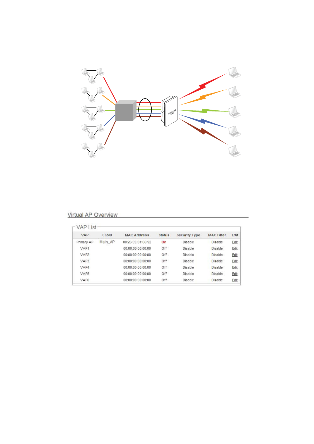
Create Virtual AP (VAP)
The TEW-676APBO support broadcasting multiple SSIDs, allowing the creation of Virtual Access Points, partitioning a
single physical access point into 7 logical access points, each of which can have a different set of security, VLAN Tag(ID)
and network settings. Figure 3-2 shows multiple SSIDs with different security type and VLAN settings.
Sales Network Resource
Engineer Network Resource
Market Network Resource
Guest Networkġ Resource
Accounting Networkġ Resource
VLAN #1
WEP
VLAN #2
VLAN #3
VLAN #4
VLAN #5
802.1Q Trunk
192.168.2.254
TEW-676APBO
WPA-PSK/TKIP
WPA-PSK/AES
WPA2-PSK/TKIP
WPA2-PSK/AES
Figure 3-2 Multiple SSIDs with different Security Type a
nd VLAN Tag
Virtual AP Overview
The administrator can view all of the Virtual AP's settings via this page.
Please click on Wireless -> Virtual AP Setup and the Virtua l AP Overview Page appears.
SSID “Sales”
SSID “Engineer”
SSID “Market”
SSID “Guest”
SSID “Accounting”
VAP : Indicate the system's Virtual AP.
ESSID : Indicate the ESSID of the respective Virtual AP
MAC Address : The MAC address of the VAP Interface is displayed here. When you enable AP and reboot system,
the MAC address will display here.
Status : Indicate the Status of the respective Virtual AP. The Primary AP always on.
Security Type : Indicate an used security type of the respective Virtual AP.
MAC Filter : Indicate an used MAC filter of the respective Virtual AP.
Edit : Click Edit button to configure Virtual AP's settings, including security type and MAC Filter.
㻞㻝
Virtual AP Setup
For each Virtual AP, administrators can configure SSID, VLAN tag(ID), SSID broadcasting, Maximum number of client
associations, security type settings.
Click Edit button on the Edit column, and then a Virtual AP setup page appears.
Enable AP : By default, it’s “Disable” for VAP1 ~ VAP6. The Primary AP always enabled.
Select “Enable” to activate VAP or click “Disable” to deactivate this function
ESSID : Extended Service Set ID, When clients are browsing for available wireless networks, this is the SSID that
will appear in the list. ESSID will determine the service type available to AP's clients associated with the specified
VAP.
Client Isolation : Select Enable, all clients will be isolated from each other, that means all clients can not reach to
other clients. Below Figures depict Client Isolation and AP Isolation
Cllent Isolation
VAP 0
Internet
Hidden SSID : By default, it’s “Disable”.
192.168.2.254
TEW-676APBO
VAP 1
VAP 2
AP Isolation
Enable this option to stop the SSID broadcast in your network. When disabled, people could easily obtain the SSID
information with the site survey software and get access to the network if security is not turned on. When enabled,
network security is enhanced. It’s suggested to enable it after AP security settings are archived and setting of AP
clients could make to associate to it.
Maximum Clients : The default value is 32. You can enter the number of wireless clients that can associate to a
particular SSID. When the number of client is set to 5, only 5 clients at most are allowed to connect to this VAP.
㻞㻞
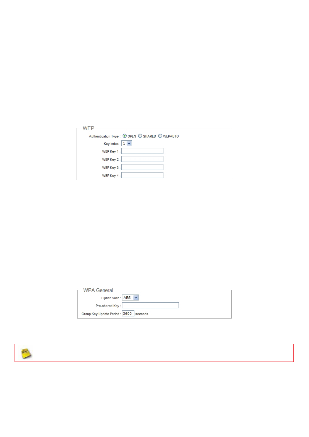
VLAN Tag(ID) : By default, it’s selected “Disable”.
This system supports tagged Virtual LAN(VLAN). A valid number of 1 to 4094 can be entered after it’s enabled. If
your network utilize VLANs you could tie a VLAN Tag to a specific SSID, and packets from/to wireless clients
belonging to that SSID will be tagged with that VLAN Tag. This enables security of wireless applications by applying
VLAN Tag.
Security Type : Select the desired security type from the drop-down list; the options are Disable, WEP, WPA-PSK,
WPA2-PSK, WPA-Enterprise, WPA2-Enterprise and WEP 802.1X.
Î Disable : Data are unencrypted during transmission when this option is selected.
Î WEP : Wired Equivalent Privacy(WEP) is a data encryption mechanism based on a 64-bit or 128-bit shared key.
Authentication Method : Enable the desire option among OPEN, SHARED or WEPAUTO.
Î Key Index : Key index is used to designate the WEP key during data transmission. 4 different WEP keys can
be entered at the same time, but only one is chosen.
Î WEP Key # : Enter HEX or ASCII format WEP key value; the system supports up to 4 sets of WEP keys.
Key Length Hex ASCII
64-bit 10 characters 5 characters
128-bit 26 characters 13 characters
Î WPA-PSK (or WPA2-PSK) : WPA (or WPA2) Algorithms, allows the system accessing the network by using the
WPA-PSK protected access.
9 Cipher Suite : By default, it is AES. Select either AES or TKIP cipher suites
9 Pre-shared Key : Enter the pre-shared key; the format shall go with the selected key type.
Pre-shared key can be entered with either a 256-bit secret in 64 HEX digits format, or 8 to 63 ASCII characters.
9 Group Key Update Period : By default, it is 3600 seconds. This time interval for rekeying GTK,
broadcast/multicast encryption keys, in seconds. Entering the time-length is required.
㻞㻟
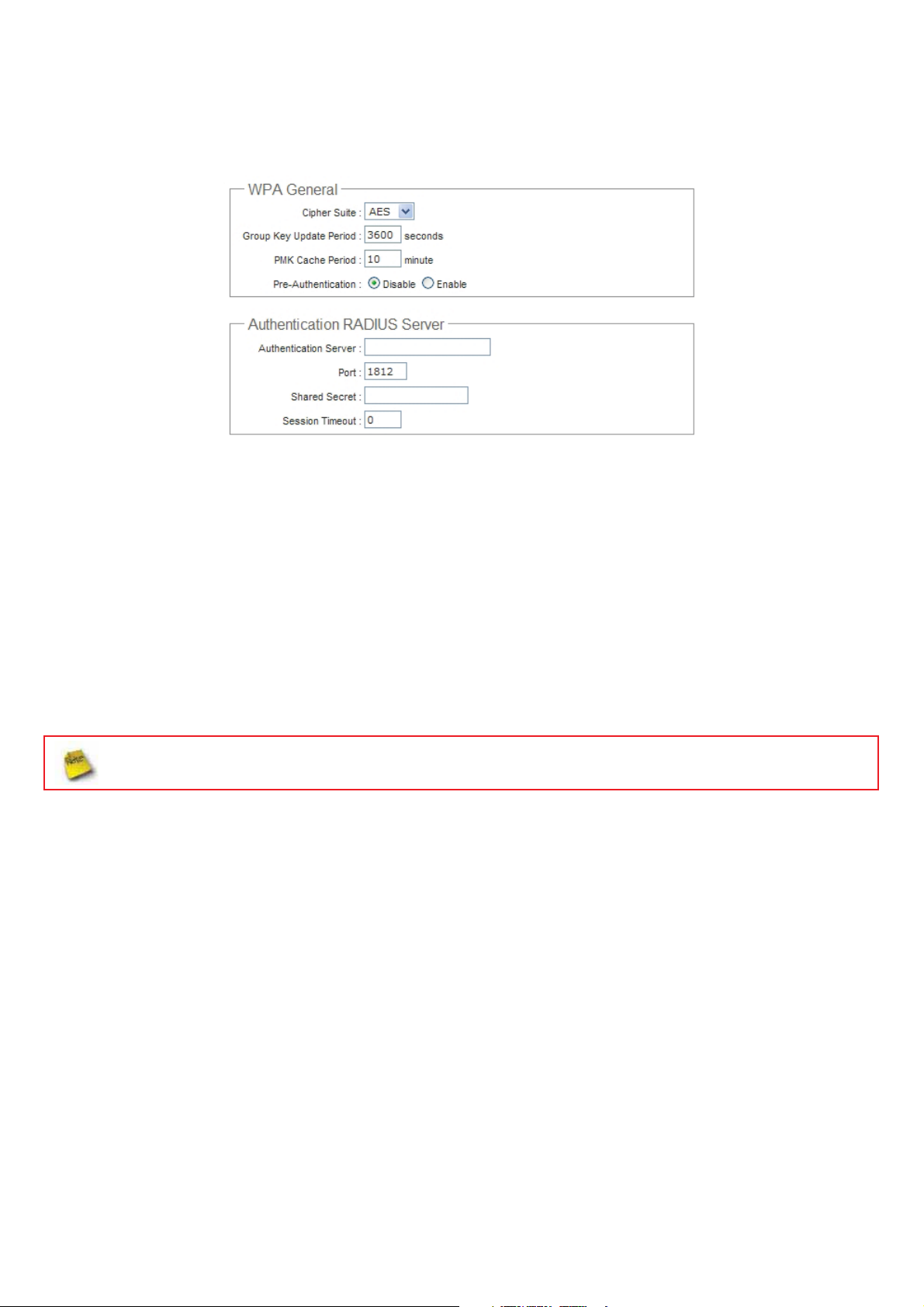
Î WPA-Enterprise (or WPA2-Enterprise): The RADIUS authentication and encryption will be both enabled if this
is selected.
9 WPA General Settings :
x Cipher Suite : By default, it is AES. Select either AES or TKIP cipher suites
x Group Key Update Period : By default, it’s 3600 seconds. This time interval for rekeying GTK,
broadcast/multicast encryption keys, in seconds. Entering the time-length is required.
x PMK Cache Period : By default, it's 10 minutes. Set WPA2 PMKID cache timeout period, after time
out, the cached key will be deleted.
x Pre-Authentication : By default, it's “Disable”. To Enable is use to speed up roaming before pre-
authenticating IEEE 802.1X/EAP part of the full RSN authentication and key handshake before actually
associating with a new AP.
PMK Cache Period and Pre-Authentication is used in WPA2-Enterprise
9 Radius Server Settings :
x IP Address : Enter the IP address of the Authentication RADIUS server.
x Port : By default, it’s 1812. The port number used to comm unicate with RADIUS server.
x Shared secret : A secret key used between system and RADIUS server. Supports 8 to 64 characters.
x Session Timeout : The Session timeout is in the range of 0~60 seconds. The default is 0 to disable
re-authenticate service.
Amount of time before a client will be required to re-authenticate.
㻞㻠
 Loading...