

i

Table of Contents
INTRODUCTION ..................................................................................................................... 1
Features .............................................................................................................................. 1
Package Contents .............................................................................................................. 3
Physical Details .................................................................................................................. 4
Wireless Performance Considerations ............................................................................ 6
PC CONFIGURATION ............................................................................................................ 7
Overview ............................................................................................................................ 7
Windows Clients ................................................................................................................ 7
Macintosh Clients ............................................................................................................ 17
Linux Clients .................................................................................................................... 17
Other Unix Systems ......................................................................................................... 17
Wireless Station Configuration ...................................................................................... 18
Wireless Configuration on Windows XP ....................................................................... 18
INSTALLATION .................................................................................................................... 27
Requirements ................................................................................................................... 27
Procedure ......................................................................................................................... 27
SETUP ...................................................................................................................................... 29
Overview .......................................................................................................................... 29
Configuration Program .................................................................................................. 30
Setup Wizard ................................................................................................................... 31
Home Screen .................................................................................................................... 34
LAN Screen ...................................................................................................................... 35
DHCP ............................................................................................................................... 35
Wireless Screen ................................................................................................................ 37
Wireless Security ............................................................................................................. 40
Trusted Wireless Stations ............................................................................................... 45
Password Screen .............................................................................................................. 47
Mode Screen ..................................................................................................................... 48
OPERATION AND STATUS ................................................................................................ 49
Operation - Router Mode ............................................................................................... 49
Status Screen .................................................................................................................... 49
Connection Status - PPPoE & PPPoA ........................................................................... 52
Connection Details - Dynamic IP Address .................................................................... 53
Connection Details - Fixed IP Address .......................................................................... 54
ADVANCED FEATURES ...................................................................................................... 55
Overview .......................................................................................................................... 55
Internet ............................................................................................................................. 55
Access Control ................................................................................................................. 58
Dynamic DNS (Domain Name Server) .......................................................................... 60
Options ............................................................................................................................. 62
Schedule............................................................................................................................ 63
Port Trigger ..................................................................................................................... 64
Port Forward ................................................................................................................... 66
Port Range Forward ....................................................................................................... 67
QoS ................................................................................................................................... 68
ADVANCED ADMINISTRATION ....................................................................................... 70
Overview .......................................................................................................................... 70
PC Database ..................................................................................................................... 71
Config File ........................................................................................................................ 75
Logs ................................................................................................................................... 76
E-mail ............................................................................................................................... 78
ii

Diagnostics ....................................................................................................................... 80
Remote Administration ................................................................................................... 81
Routing ............................................................................................................................. 83
Upgrade Firmware .......................................................................................................... 87
MODEM MODE ..................................................................................................................... 88
Overview .......................................................................................................................... 88
Management Connections .............................................................................................. 88
Home Screen .................................................................................................................... 89
Mode Screen ..................................................................................................................... 90
Operation ......................................................................................................................... 90
Status Screen .................................................................................................................... 91
APPENDIX .............................................................................................................................. 93
Troubleshooting ............................................................................................................... 93
General Problems ............................................................................................................ 93
Internet Access ................................................................................................................. 93
Wireless Access ................................................................................................................ 94
About Wireless LANs ...................................................................................................... 95
BSS/ESS............................................................................................................................ 95
Channels ........................................................................................................................... 95
WEP .................................................................................................................................. 96
WPA-PSK ........................................................................................................................ 96
WPA2-PSK ...................................................................................................................... 96
WPA-802.1x ..................................................................................................................... 97
Wireless LAN Configuration .......................................................................................... 97
Specifications ................................................................................................................... 98
Regulatory Approvals ................................................................................................... 100
Limited Warranty ......................................................................................................... 101
P/N: 956YQN0001
Copyright © 2009. All Rights Reserved.
Document Version: 1.1
All trademarks and trade names are the properties of their respective owners.

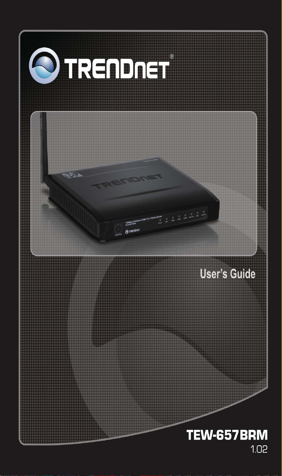
Introduction
Congratulations on the purchase of your new TEW-657BRM. The 150Mbps Wireless N
ADSL 2/2+ Modem Router is a multi-function device providing the following services:
ADSL Modem.
•
Shared Broadband Internet Access for all LAN users.
•
Wireless Access Point for 802.11b, 802.11g and 802.11n Wireless Stations.
•
4-Port Switching Hub for 10BaseT or 100BaseT connections.
•
Features
The 150Mbps Wireless N ADSL 2/2+ Modem Router incorporates many advanced features,
carefully designed to provide sophisticated functions while being easy to use.
Internet Access Features
• Shared Internet Access. All users on the LAN or WLAN can access the Internet
through the Wireless ADSL Router, using only a single external IP Address. The local
(invalid) IP Addresses are hidden from external sources. This process is called NAT
(Network Address Translation).
Built-in ADSL Modem. The Wireless ADSL Router has a built-in ADSL modem,
•
supporting all common ADSL connections.
IPoA, PPPoE, PPPoA, Direct Connection Support. The Wireless ADSL Router
•
supports all common connection methods.
Auto-detection of Internet Connection Method. In most situations, the Wireless
•
ADSL Router can test your ADSL and Internet connection to determine the connection
method used by your ISP.
Fixed or Dynamic IP Address. On the Internet (ADSL port) connection, the Wireless
•
ADSL Router supports both Dynamic IP Address (IP Address is allocated on connection)
and Fixed IP Address.
1

Advanced Internet Functions
• Application Level Gateways (ALGs). Applications which use non-standard connec-
tions or port numbers are normally blocked by the Firewall. The ability to defin e and
allow such applications is provided, to enable such applications to be used normally.
Dynamic DNS Support. DDNS, when used with the Virtual Servers feature, allows
•
users to connect to Servers on your LAN using a Domain Name, even if you have a dynamic IP address which changes every time you connect.
URL Filter. Use the URL Filter to block access to undesirable Web sites by LAN users.
•
Access Control. Using the Access Control feature, you can assign LAN users to differ-
•
ent groups, and determine which Internet services are available to each group.
Firewall. As well as the built-in firewall to protect your LAN, you can define Firewall
•
Rules to determine which incoming and outgoing traffic should be permitted.
Scheduling. Both the URL Filter and Firewall rules can be scheduled to operate only at
•
certain times. This provides great flexibility in controlling Internet -bound traffic.
Logs. Define what data is recorded in the Logs, and optionally send log data to a Syslog
•
Server. Log data can also be E-mailed to you.
Port Triggering. This feature, also called Special Applications, allows you to use
•
Internet applications which normally do not function when used behind a firewall.
Port Forwarding. This feature allows Internet users to access Internet servers on your
•
LAN. The required setup is quick and easy.
QoS Support Quality of Service can be used to handle packets so that more important
•
connections receive priority over less important one.
VPN Pass through Support. PCs with VPN (Virtual Private Networking) software
•
using PPTP, L2TP and IPSec are transparently supported - no configuration is required.
Wireless Features
• Standards Compliant. The Wireless ADSL Router complies with the IEEE802.11g
(DSSS) specifications for Wireless LANs.
Supports 11n Wireless Stations. The 802.11n Draft standard provides for backward
•
compatibility with the 802.11b standard, so 802.11n, 802.11b and 802.11g Wireless stations can be used simultaneously.
WEP support. Support for WEP (Wired Equivalent Privacy) is included. Key sizes of
•
64 Bit and 128 Bit are supported. WEP encrypts any data before transmission, providing
protection against snoopers.
WPA-PSK support. Like WEP, WPA-PSK encrypts any data before transmission,
•
providing protection against snoopers. The WPA-PSK is a later standard than WEP, and
provides both easier configuration and greater security than WEP.
WPA2-PSK support. Support for WPA2 is also included. WPA2 uses the extremely
•
secure AES encryption method.
802.1x Support. Support for 802.1x mode is included, providing for the industrial-
•
strength wireless security of 802.1x authentication and authorization.
Wireless MAC Access Control. The Wireless Access Control feature can check the
•
MAC address (hardware address) of Wireless stations to ensure that only trusted Wireless
Stations can access your LAN.
WPS Support. WPS (Wi-Fi Protected Setup) can simplify the process of connecting any
•
device to the wireless network by using the push button configuration (PBC) on the Wireless Access Point, or entering PIN code if there's no button.
• WDS Support. Support for WDS (Wireless Distribution System) allows the Wireless
Access Point to act as a Wireless Bridge. Both Point-to-Point and Multi-Po int Bridge
modes are supported.
2

• Simple Configuration. If the default settings are unsuitable, they can be changed
quickly and easily.
LAN Features
• 4-Port Switching Hub. The Wireless ADSL Router incorporates a 4-port 10/100BaseT
switching hub, making it easy to create or extend your LAN.
DHCP Server Support. Dynamic Host Configuration Protocol provides a dynamic IP
•
address to PCs and other devices upon request. The Wireless ADSL Router can act as a
DHCP Server for devices on your local LAN and WLAN.
Configuration & Management
• Easy Setup. Use your WEB browser from anywhere on the LAN or WLAN for configu-
ration.
Configuration File Upload/Download. Save (download) the configuration data from
•
the Wireless ADSL Router to your PC, and restore (upload) a previously-saved configuration file to the Wireless ADSL Router.
Remote Management. The Wireless ADSL Router can be managed from any PC on
•
your LAN or Wireless LAN. And, if the Internet connection exists, it can also (optionally)
be configured via the Internet.
Network Diagnostics. You can use the Wireless ADSL Router to perform a Ping or
•
DNS lookup.
Security Features
• Password - protected Configuration. Password protection is provided to prevent
unauthorized users from modifying the configuration data and settings.
Wireless LAN Security. WPA-PSK, WEP and Wireless access control by MAC ad-
•
dress are all supported. The MAC-level access control feature can be used to prevent
unknown wireless stations from accessing your LAN.
NAT Protection. An intrinsic side effect of NAT (Network Address Translation) tech-
•
nology is that by allowing all LAN users to share a single IP address, the location and
even the existence of each PC is hidden. From the external viewpoint, there is no network,
only a single device - the Wireless ADSL Router.
Firewall. All incoming data packets are monitored and all incoming server requests are
•
filtered, thus protecting your network from malicious attacks from external sources.
Protection against DoS attacks. DoS (Denial of Service) attacks can flood your
•
Internet connection with invalid packets and connection requests, using so much bandwidth and so many resources that Internet access becomes unavailable. The Wireless
ADSL Router incorporates protection against DoS attacks.
Package Contents
The following items should be included. If any of these items are damaged or missing, please
contact your dealer immediately.
• TEW-657BRM
• CD-ROM (User’s Guide)
• Quick Installation Guide
• Power adapter (12V DC, 1A)
• Cat. 5 Ethernet cable (1.5m / 5ft.)
• RJ-11 telephone cable (0.9m / 3ft.)

Physical Details
Front-mounted LEDs
WPS Button
Push the WPS button on the device and your other wireless device to
perform WPS function that easily creates an encryption-secured wireless
connection automatically.
When WPS button is pressed, the LED will start blinking for 2 minutes. If
any client is associated with the router successfully within 2 minutes, the
LED will stay On, otherwise the LED will be Off.
Power LED
(Orange)
LAN (Blue) On - The LAN port is active.
WLAN (Blue) On -
ADSL
(Green)
Internet
(Blue/Yellow)
On - Power on.
Off - No power.
Off - No active connection on the LAN (Ethernet) port.
Flashing - Data is being transmitted or received via the corresponding
LAN port.
When wireless client have connected
Off - No Wireless connections currently exist.
Flashing - Data is being transmitted or received via the Wireless access
point. This includes "network traffic" as well as user data.
On - ADSL connection established.
Off - No ADSL connection currently exists.
Flashing - ADSL is synchronizing.
On (Blue) - Internet connection is available.
Off - No Internet connection available.
Flashing (Blue) - Data is being transmitted or received via the ADSL
connection.
4
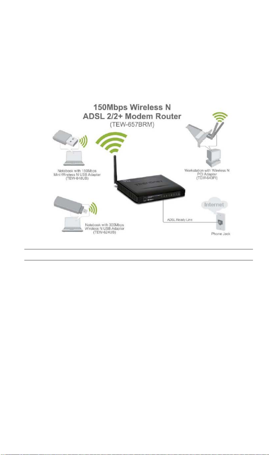
Rear Panel
ADSL port
Connect this port to your ADSL line.
10/100BaseT
LAN connections
Reset Button
(Reset to Defaults)
Power port
Use standard LAN cables (RJ45 connectors) to connect your PCs to
these ports.
Note:
Any LAN port on the Wireless ADSL Router will automatically
function as an "Uplink" port when required. Just connect any port to
a normal port on the other hub, using a standard LAN cable.
This button will reset the Wireless ADSL Router to the factory
default settings.
To do this, press and hold the Reset Button for five (5) seconds, until
the Status LED is lit, then release the Reset Button, and wait the
Wireless ADSL Router to restart using the factory default values.
Connect the supplied power adapter here.

Wireless Performance Considerations
There are a number of factors that can impact the range of wireless devices.
1. Adjust your wireless devices so that the signal is traveling in a straight path, rather than at
an angle. The more material the signal has to pass through the more signal you will lose.
2. Keep the number of obstructions to a minimum. Each obstruction can reduce the range of
a wireless device. Position the wireless devices in a manner that will minimize the amount
of obstructions between them.
3. Building materials can have a large impact on your wireless signal. In an indoor environ-
ment, try to position the wireless devices so that the signal passes through less dense
material such as dry wall. Dense materials like metal, solid wood, glass or even furniture
may block or degrade the signal.
4. Antenna orientation can also have a large impact on your wireless signal. Use the wireless
adapter’s site survey tool to determine the best antenna orientation for your wireless devices.
5. Interference from devices that produce RF (radio frequency) noise can also impact your
signal. Position your wireless devices away from anything that generates RF noise, such as
microwaves, radios and baby monitors.
6. Any device operating on the 2.4GHz frequency will cause interference. Devices such as
2.4GHz cordless phones or other wireless remotes operating on the 2.4GHz frequency can
potentially drop the wireless signal. Although the phone may not be in use, the base can
still transmit wireless signal. Move the phone’s base station as far away as possible from
your wireless devices.
If you are still experiencing low or no signal consid er repositioning the wireless devices or
installing additional access points. The use of higher gain antennas may also provide the
necessary coverage depending on the environment.
6

PC Configuration
Overview
For each PC, the following may need to be configured:
• TCP/IP network settings
• Internet Access configuration
• Wireless configuration
Windows Clients
This section describes how to configure Windows clients for Internet access via the Wireless
ADSL Router.
The first step is to check the PC's TCP/IP settings.
The Wireless ADSL Router uses the TCP/IP network protocol for all functions, so it is essen-
tial that the TCP/IP protocol be installed and configured on each PC.
TCP/IP Settings - Overview
If using the default Wireless ADSL Router settings, and the default Windows TCP/IP settings, no changes need to be made.
• By default, the Wireless ADSL Router will act as a DHCP Server, automatically providing
a suitable IP Address (and related information) to each PC when the PC boots.
• For all non-Server versions of Windows, the default TCP/IP setting is to act as a DHCP
client.
If using a Fixed (specified) IP address, the following changes are required:
• The Gateway must be set to the IP address of the Wireless ADSL Router
• The DNS should be set to the address provided by your ISP.
If your LAN has a Router, the LAN Administrator must reconfigure the Router itself. Refer to Chapter 8 - Ad-
vanced Setup for details.
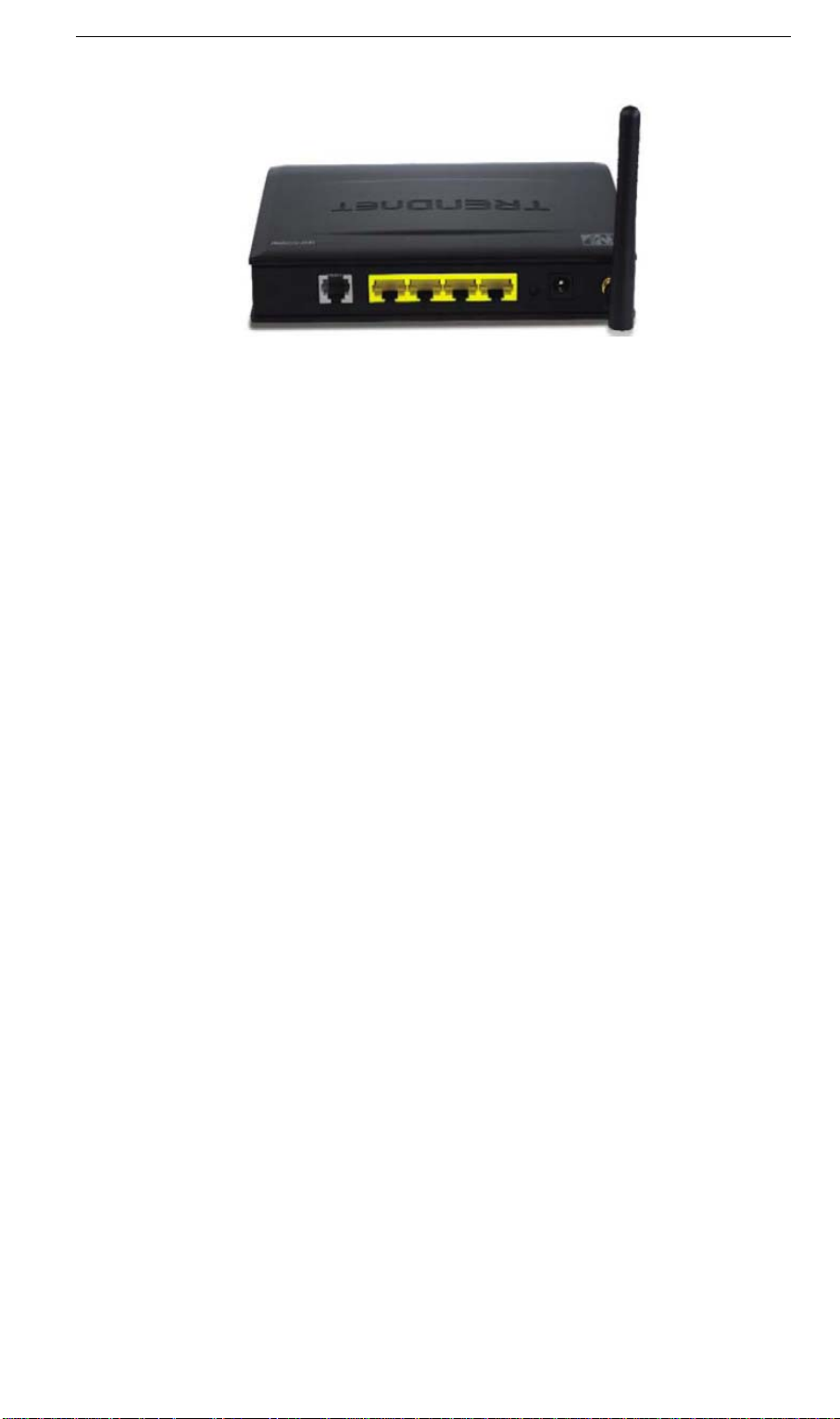
Checking TCP/IP Settings - Windows 9x/ME:
1. Select Control Panel - Network. You should see a screen like the following:
2. Select the TCP/IP protocol for your network card.
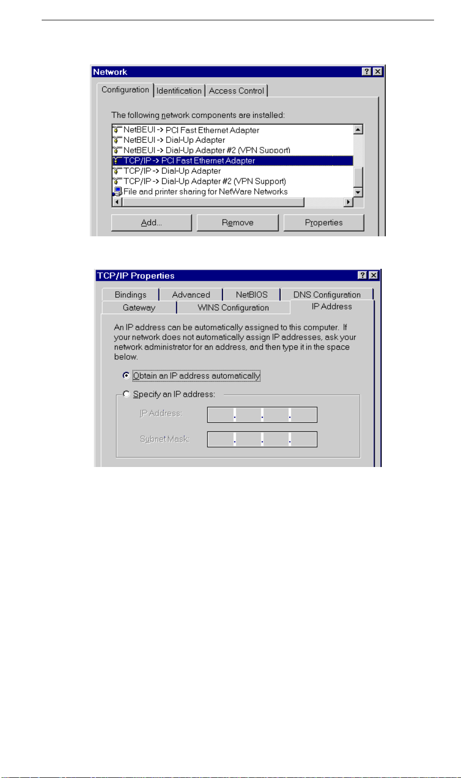
3. Click on the Properties button. You should then see a screen like the following.
Ensure your TCP/IP settings are correct, as follows:
Using DHCP
To use DHCP, select the radio button Obtain an IP Address automatically. This is the default
Windows setting. Using this is recommended. By default, the Wireless ADSL Router will act
as a DHCP Server.
Restart your PC to ensure it obtains an IP Address from the Wireless ADSL Router.
Using "Specify an IP Address"
If your PC is already configured, check with your network administrator before making the
following changes:
• On the Gateway tab, enter the Wireless ADSL Router's IP address in the New Gateway
field and click Add, as shown below. Your LAN administrator can advise you of the IP
Address they assigned to the Wireless ADSL Router.
8
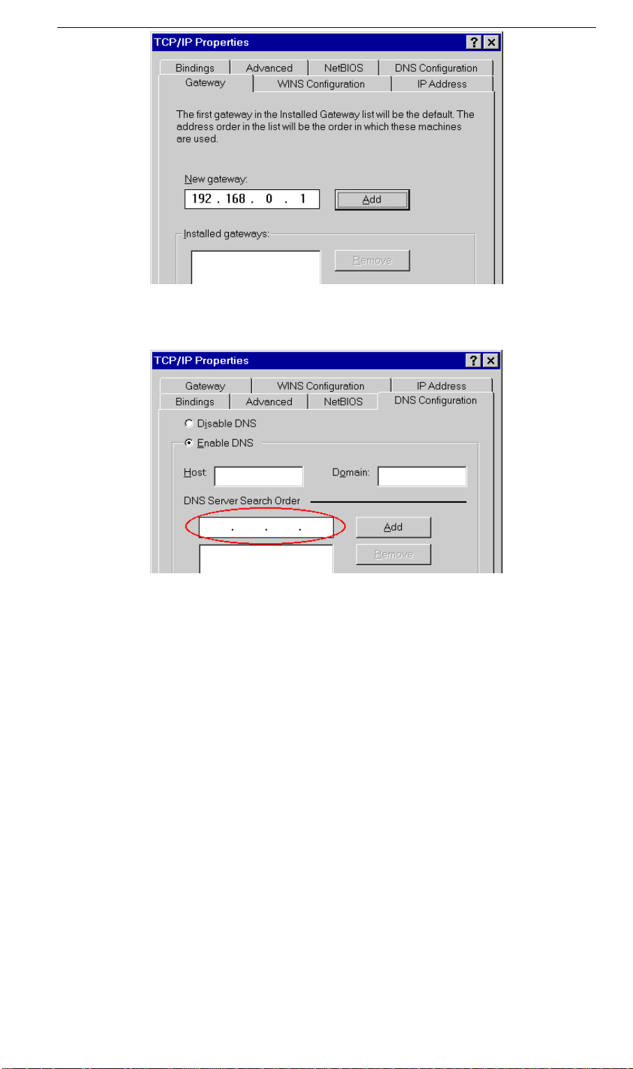
• On the DNS Configuration tab, ensure Enable DNS is selected. If the DNS Server Search
Order list is empty, enter the DNS address provided by your ISP in the fields beside the
Add button, then click Add.
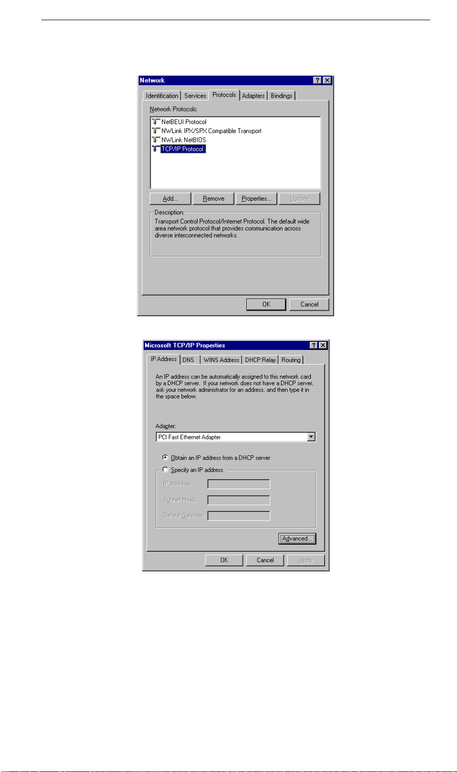
Checking TCP/IP Settings - Windows NT4.0
1. Select Control Panel - Network, and, on the Protocols tab, select the TCP/IP protocol, as
shown below.
2. Click the Properties button to see a screen like the one below.
3. Select the network card for your LAN.
4. Select the appropriate radio button - Obtain an IP address from a DHCP Server or Specify
an IP Address, as explained below.
Obtain an IP address from a DHCP Server
This is the default Windows setting. Using this is recommended. By default, the Wireless
ADSL Router will act as a DHCP Server.
Restart your PC to ensure it obtains an IP Address from the Wireless ADSL Router.
10
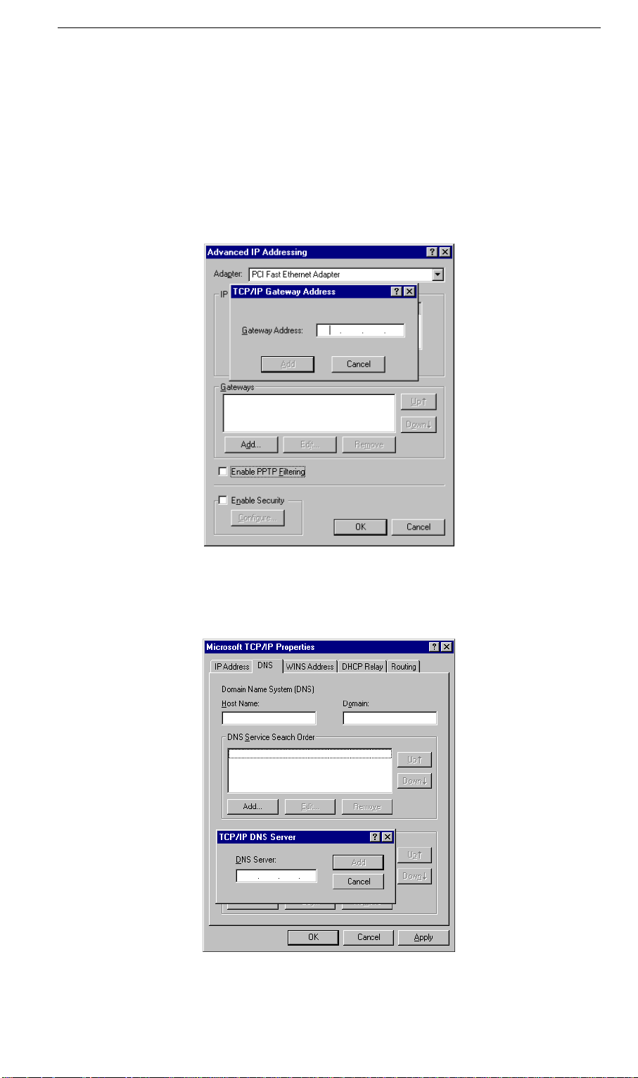
Specify an IP Address
If your PC is already configured, check with your network administrator before making the
following changes.
1. The Default Gateway must be set to the IP address of the Wireless ADSL Router. To set
this:
• Click the Advanced button on the screen above.
• On the following screen, click the Add button in the Gateways panel, and enter the
Wireless ADSL Router's IP address, as shown in Figure 26 below.
• If necessary, use the Up button to make the Wireless ADSL Router the first entry in
the Gateways list.
2. The DNS shoul SP, as f lows:
d be set to the address provided by your I ol
• Click the DNS tab.
• On the DNS screen,
shown below, click the Add button (under DNS Service Search
Order), and enter the DNS provided by your ISP.
Checking TCP/IP Settings - Windows 2000:
1. Select Control Panel - Network and Dial-up Connection.
2. Right - click the Local Area Connection icon and select Properties. You should see a
screen like the following:
3. Select the TCP/IP protocol for your network card.
4. Click on the Properties button. You should then see a screen like the following.
5. Ensure your TCP/IP settings are correct, as described below.
Using DHCP
To use DHCP, select the radio button Obtain an IP Address automatically. This is the default
Windows setting. Using this is recommended. By default, the Wireless ADSL Router will act
as a DHCP Server.
12

Restart your PC to ensure it obtains an IP Address from the Wireless ADSL Router.
Using a fixed IP Address ("Use the following IP Address")
If your PC is already configured, check with your network administrator before making the
following changes.
• Enter the Wireless ADSL Router's IP address in the Default gateway field and click OK.
(Your LAN administrator can advise you of the IP Address they assigned to the Wireless
ADSL Router.)
• If the DNS Server fields are empty, select Use the following DNS server addresses, and
enter the DNS address or addresses provided by your ISP, then click OK.
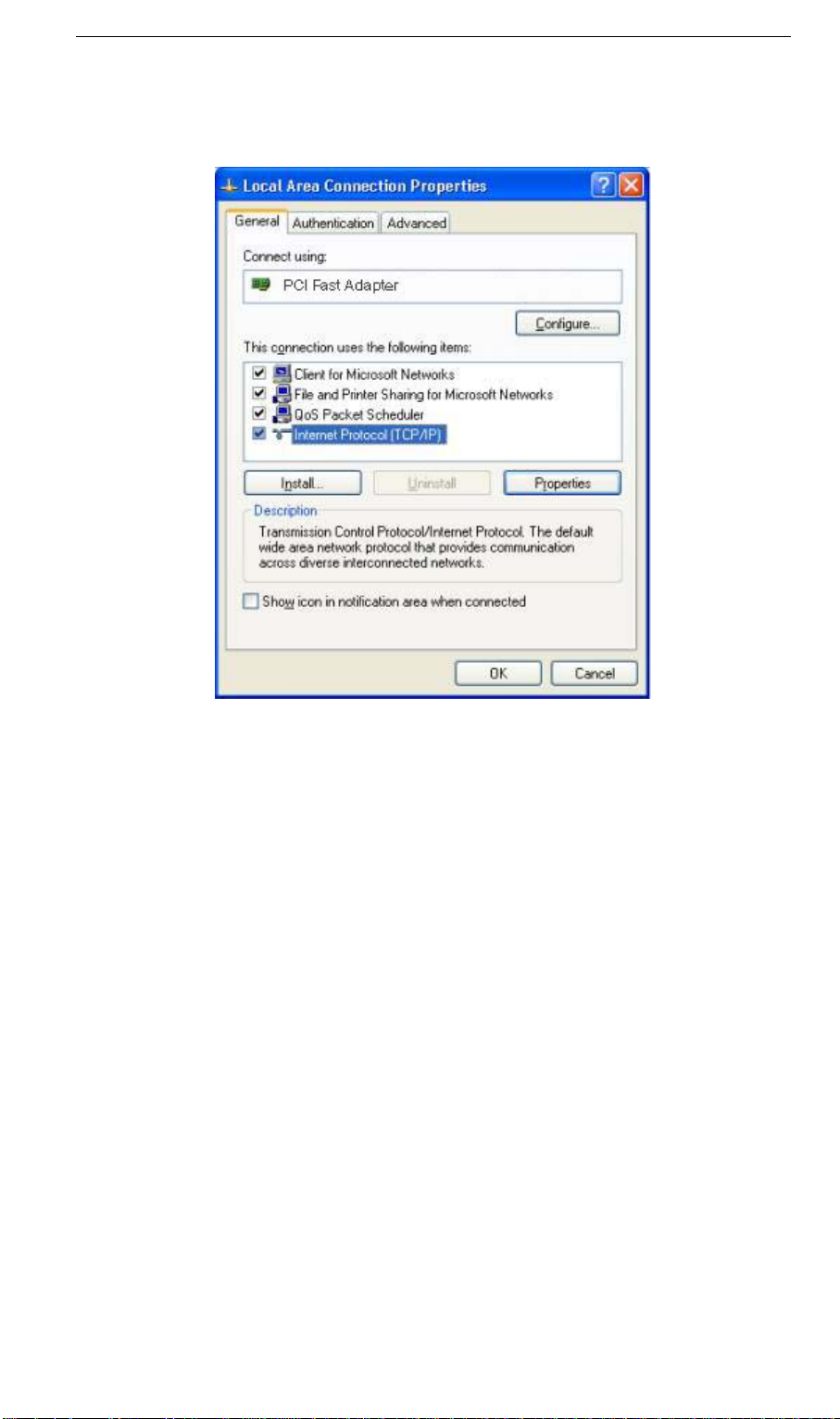
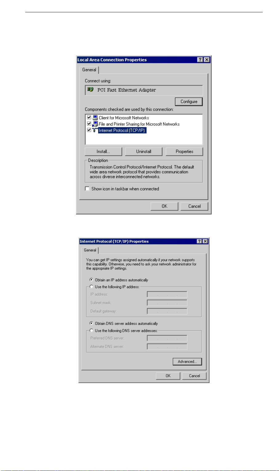
Checking TCP/IP Settings - Windows XP
1. Select Control Panel - Network Connection.
2. Right click the Local Area Connection and choose Properties. You should see a screen
like the following:
3. Select the TCP/IP protocol for your network card.
4. Click on the Properties button. You should then see a screen like the following.
14
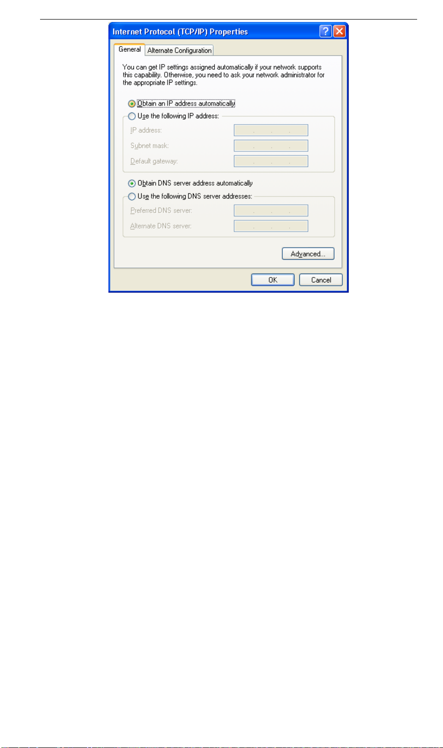
5. Ensure your TCP/IP settings are correct.
Using DHCP
To use DHCP, select the radio button Obtain an IP Address automatically. This is the default
Windows setting. Using this is recommended. By default, the Wireless ADSL Router will act
as a DHCP Server.
Restart your PC to ensure it obtains an IP Address from the Wireless ADSL Router.
Using a fixed IP Address ("Use the following IP Address")
If your PC is already configured, check with your network administrator before making the
following changes.
• In the Default gateway field, enter the Wireless ADSL Router's IP address and click OK.
Your LAN administrator can advise you of the IP Address they assigned to the Wireless
ADSL Router.
• If the DNS Server fields are empty, select Use the following DNS server addresses, and
enter the DNS address or addresses provided by your ISP, then click OK.

Internet Access
To configure your PCs to use the Wireless ADSL Router for Internet access:
• Ensure that the DSL modem, Cable modem, or other permanent connection is functional.
• Use the following procedure to configure your Browser to access the Internet via the LAN,
rather than by a Dial-up connection.
For Windows 9x/ME/2000
1. Select Start Menu - Settings - Control Panel - Internet Options.
2. Select the Connection tab, and click the Setup button.
3. Select "I want to set up my Internet connection manually, or I want to connect through a
local area network (LAN)" and click Next.
4. Select "I connect through a local area network (LAN)" and click Next.
5. Ensure all of the boxes on the following Local area network Internet Configuration screen
are unchecked.
6. Check the "No" option when prompted "Do you want to set up an Internet mail account
now?".
7. Click Finish to close the Internet Connection Wizard.
Setup is now completed.
For Windows XP
1. Select Start Menu - Control Panel - Network and Internet Connections.
2. Select Set up or change your Internet Connection.
3. Select the Connection tab, and click the Setup button.
4. Cancel the pop-up "Location Information" screen.
5. Click Next on the "New Connection Wizard" screen.
6. Select "Connect to the Internet" and click Next.
7. Select "Set up my connection manually" and click Next.
8. Check "Connect using a broadband connection that is always on" and click Next.
9. Click Finish to close the New Connection Wizard.
Setup is now completed.
Accessing AOL
To access AOL (America On Line) through the Wireless ADSL Router, the AOL for Windows
software must be configured to use TCP/IP network access, rather than a dial-up connection.
The configuration process is as follows:
• Start the AOL for Windows communication software. Ensure that it is Version 2.5, 3.0 or
later. This procedure will not work with earlier versions.
• Click the Setup button.
• Select Create Location, and change the location name from "New Locality" to "Wireless
ADSL Router".
• Click Edit Location. Select TCP/IP for the Network field. (Leave the Phone Number
blank.)
• Click Save, then OK.
Configuration is now complete.
• Before clicking "Sign On", always ensure that you are using the "Wireless ADSL Router"
location.
16

Macintosh Clients
From your Macintosh, you can access the Internet via the Wireless ADSL Router. The procedure is as follows.
1. Open the TCP/IP Control Panel.
2. Select Ethernet from the Connect via pop-up menu.
3. Select Using DHCP Server from the Configure pop-up menu. The DHCP Client ID field
can be left blank.
4. Close the TCP/IP panel, saving your settings.
Note:
If using manually assigned IP addresses instead of DHCP, the required changes are:
• Set the Router Address field to the Wireless ADSL Router's IP Address.
• Ensure your DNS settings are correct.
Linux Clients
To access the Internet via the Wireless ADSL Router, it is only necessary to set the Wireless
ADSL Router as the "Gateway".
Ensure you are logged in as "root" before attempting any changes.
Fixed IP Address
By default, most Unix installations use a fixed IP Address. If you wish to continue using a
fixed IP Address, make the following changes to your configuration.
• Set your "Default Gateway" to the IP Address of the Wireless ADSL Router.
• Ensure your DNS (Name server) settings are correct.
To act as a DHCP Client (recommended)
The procedure below may vary according to your version of Linux and X -windows shell.
1. Start your X Windows client.
2. Select Control Panel - Network
3. Select the "Interface" entry for your Network card. Normally, this will be called "eth0".
4. Click the Edit button, set the "protocol" to "DHCP", and save this data.
5. To apply your changes
• Use the "Deactivate" and "Activate" buttons, if available.
• OR, restart your system.
Other Unix Systems
To access the Internet via the Wireless ADSL Router:
• Ensure the "Gateway" field for your network card is set to the IP Address of the Wireless
ADSL Router.
• Ensure your DNS (Name Server) settings are correct.
Wireless Station Configuration
This section applies to all Wireless stations wishing to use the Wireless ADSL Router's Access
Point, regardless of the operating system which is used on the client.
To use the Wireless Access Point in the Wireless ADSL Router, each Wireless Station must
have compatible settings, as follows:
Mode
SSID (ESSID)
Wireless
Security
The mode must be set to Infrastructure (rather than Ad-hoc)
Access points only operate in Infrastructure mode.
This must match the value used on the Wireless ADSL Router. The
default value is Admin.
Note! The SSID is case sensitive.
By default, Wireless security on the Wireless ADSL Router is disabled.
• If Wireless security remains disabled on the Wireless ADSL Router,
all stations must have wireless security disabled.
• If Wireless security is enabled on the Wireless Router, each station
must use the same settings as the Wireless ADLS Router.
Wireless Configuration on Windows XP
If using Windows XP to configure the Wireless interface on your PC, the configuration procedure is as follows:
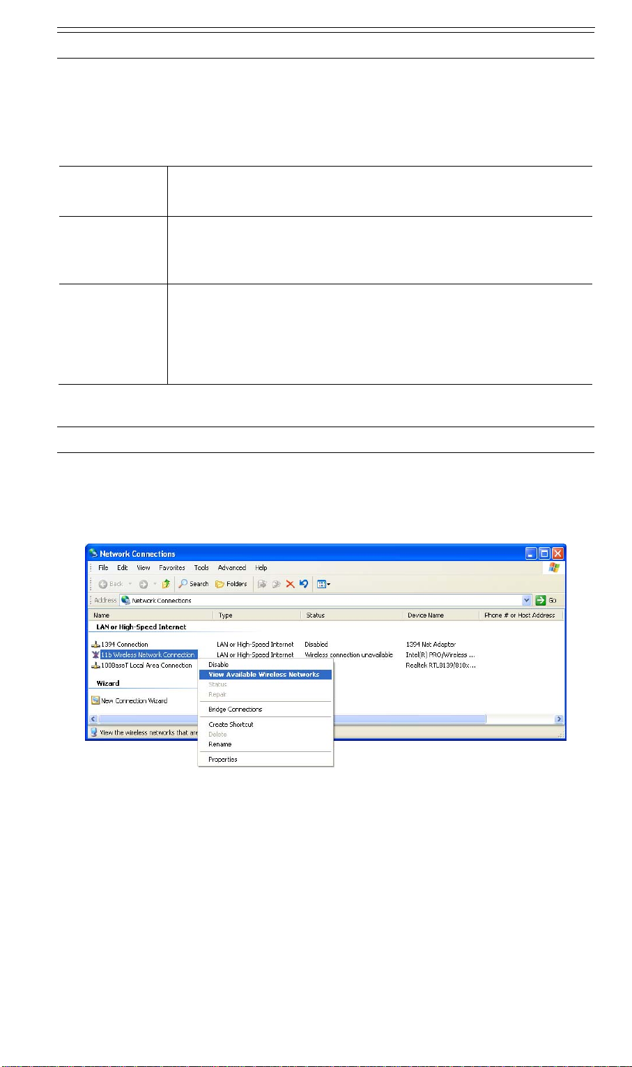
1. Open the Network Connections folder. (Start - Settings - Network Connections).
2. Right-click the Wireless Network Connection, check that it is enabled (menu option says
Disable, rather than Enable) and then select View Available Wireless Networks.
3. You will then see a list of wireless networks.
18
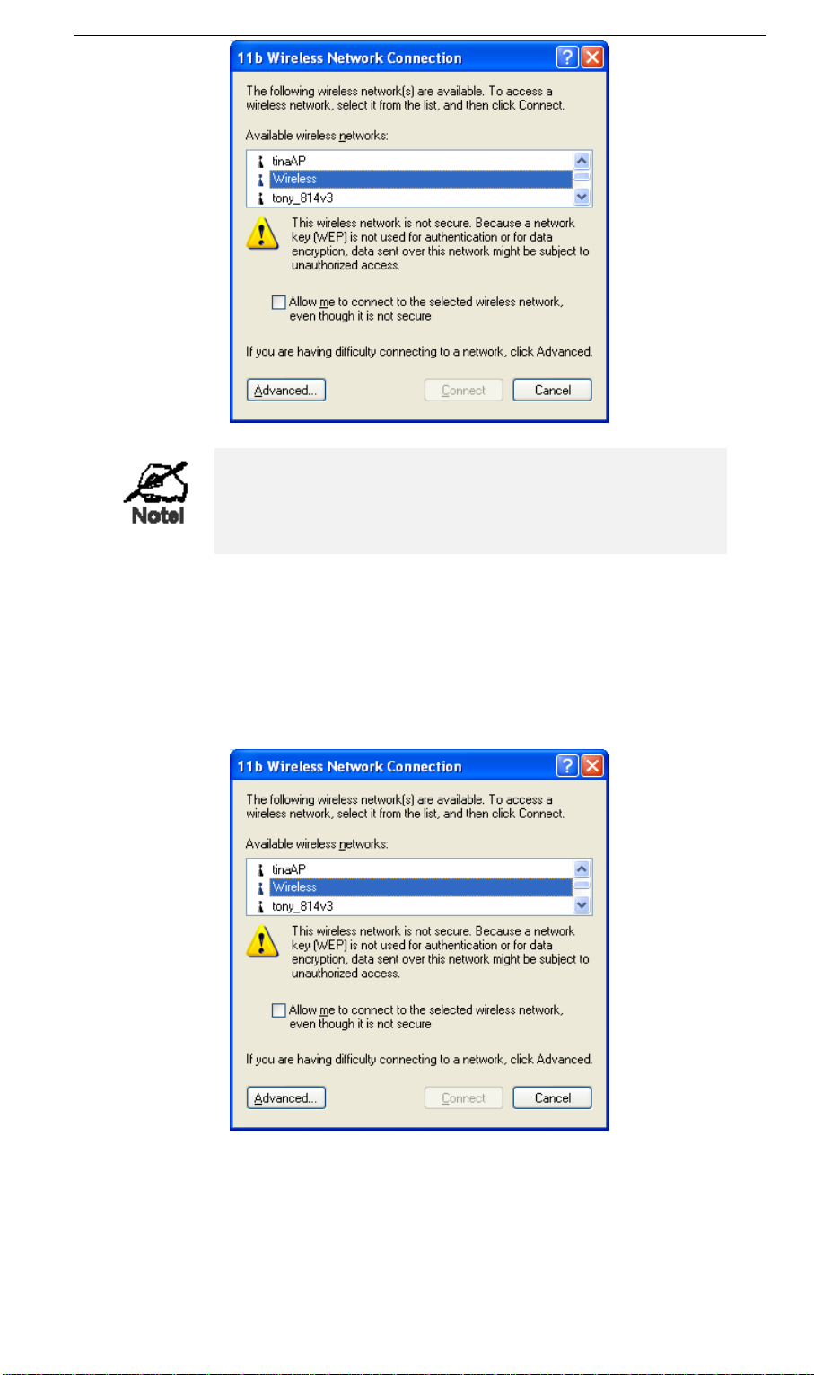
If the "Broadcast SSID" setting on the Wireless ADSL
Router has been disabled, its SSID will NOT be listed.
See the following section "If the SSID is not listed" for
details of dealing with this situation.
4. The next step depends on whether or not Wireless security has been enabled on the Wire-
less ADSL Router.
If Wireless Security is Disabled
If Wireless security on the Wireless ADSL Router is disabled, Windows will warn you that the
Wireless network is not secure.
To connect:
• Check the checkbox Allow me to connect to the selected wireless network, even though it
is not secure.
• The Connect button will then be available. Click the Connect button, and wait a few
seconds for the connection to be established.
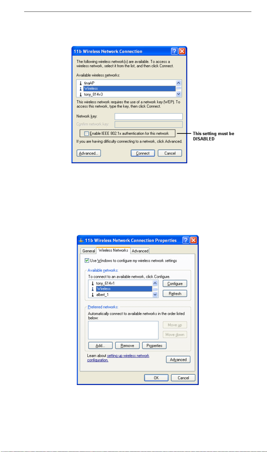
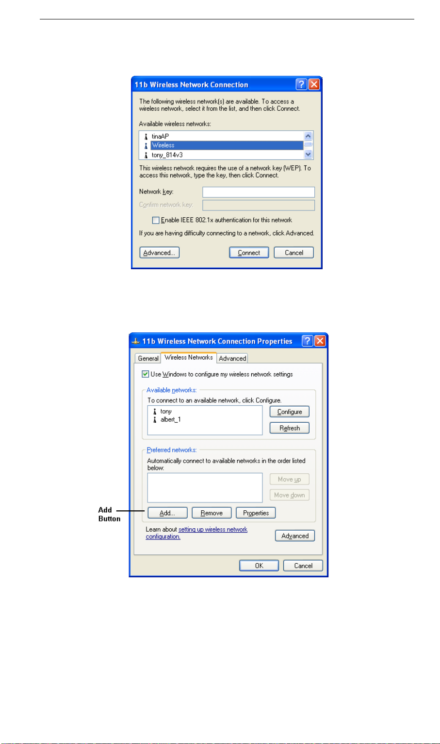
If using WEP Data Encryption
If WEP data encryption has been enabled on the Wireless ADSL Router, Windows will detect
this, and show a screen like the following.
To connect:
• Enter the WEP key, as set on the Wireless ADSL Router, in the Network Key field.
• Re-enter the WEP key into the Confirm Network key field.
• Disable the checkbox Enable IEEE 802.1x authentication for this network.
• Click the Connect button.
If this fails, click the Advanced button, to see a screen like the following:
Select the SSID for the Wireless ADSL Router, and click Configure, to see a screen like the
following:
20
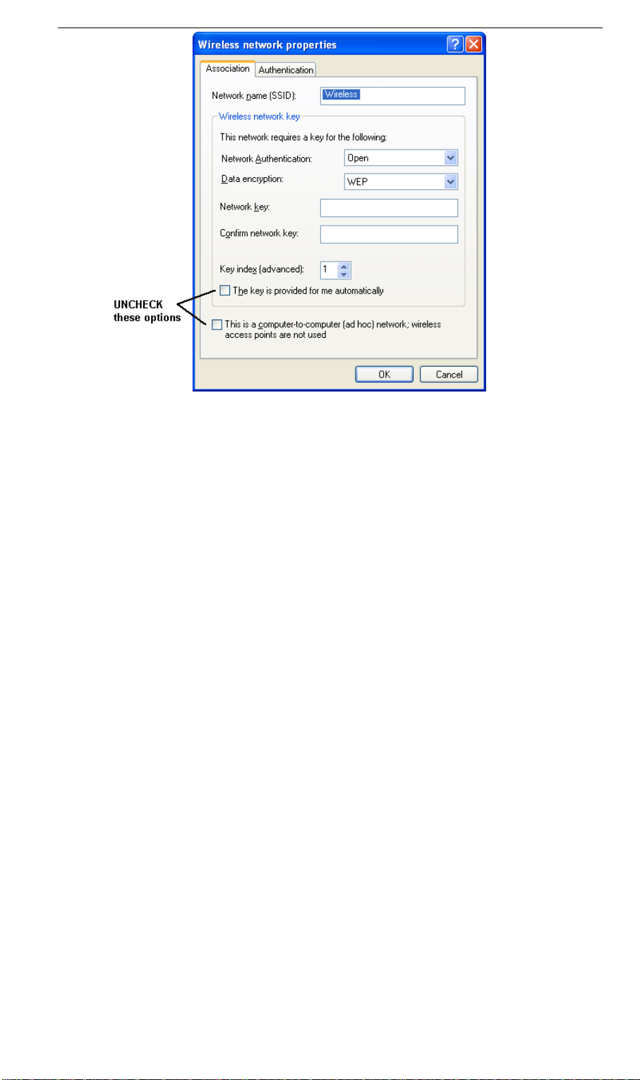
Configure this screen as follows:
• Set Network Authentication to match the Wireless ADSL Router. (If the setting on the
Wireless ADSL Router is "Auto", then either Open or Shared can be used.)
• For Data Encryption, select WEP.
• For the Network key and Confirm network key, enter the default key value used on the
Wireless ADSL Router. (Windows will determine if 64bit or 128bit encryption is used.)
• The Key index must match the default key index on the Wireless ADSL Router. The
default value is 1.
• Ensure the options The key is provided for me automatically and This is a computer-to-
computer (ad hoc) network are unchecked.
• Click OK to save and close this dialog.
• This wireless network will now be listed in Preferred Networks on the screen below.
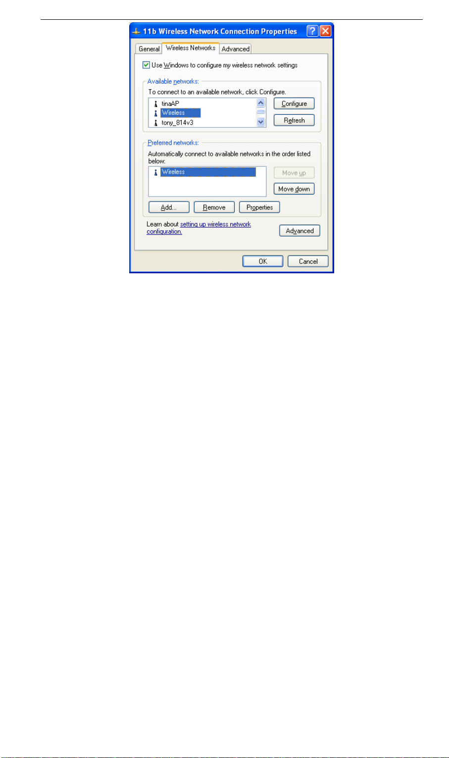
Click OK to establish a connection to the Wireless ADSL Router.
22
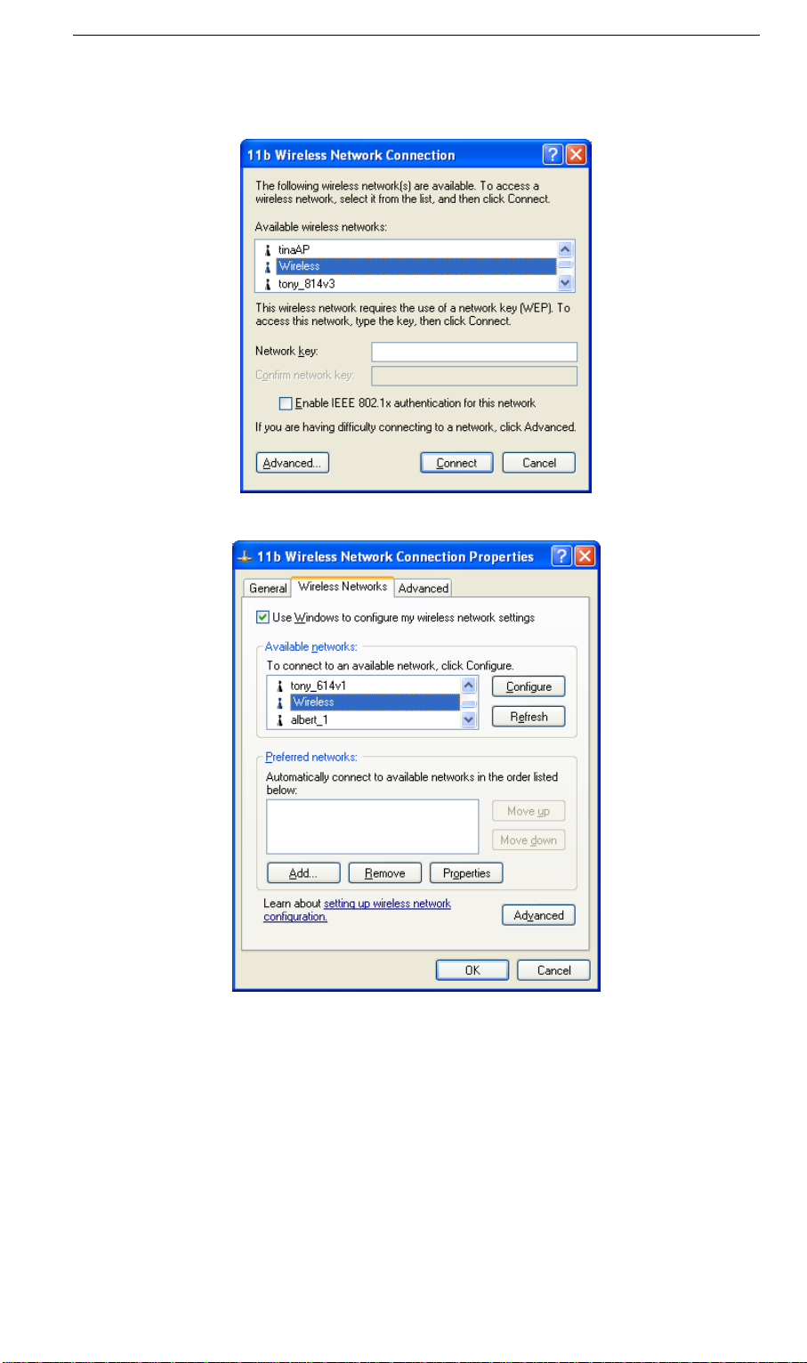
If using WPA-PSK Data Encryption
If WPA-PSK data encryption has been enabled on the Wireless ADSL Router, it does not
matter which network is selected on the screen below. Just click the Advanced button.
You will then see a screen like the example below.
Select the SSID for the Wireless ADSL Router, and click Configure, to see a screen like the
following:
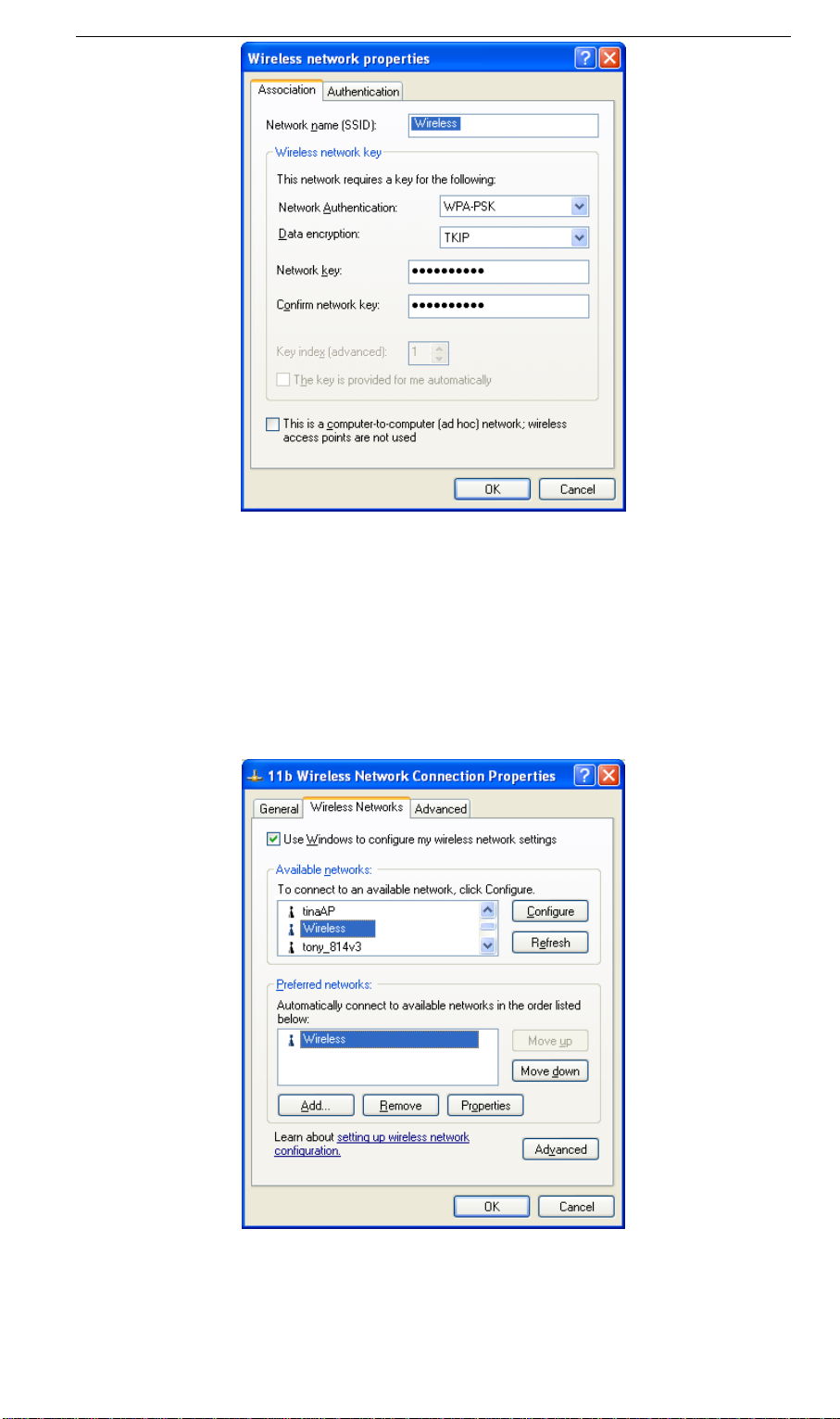
Configure this screen as follows:
• Set Network Authentication to WPA-PSK.
• For Data Encryption, select TKIP.
• For the Network key and Confirm network key, enter the network key (PSK) used on the
Wireless ADSL Router.
• Ensure the option This is a computer-to-computer (ad hoc) network is unchecked.
• Click OK to save and close this dialog.
• This wireless network will now be listed in Preferred Networks on the screen below.
Click OK to establish a connection to the Wireless ADSL Router.
24
If the SSID is not listed
If the "Broadcast SSID" setting on the Wireless ADSL Router has been disabled, its SSID will
NOT be listed on the screen below.
In this situation, you need to obtain the SSID from your network administrator, then follow
this procedure:
1. Click the Advanced button to see a screen like the example below.
2. Click the Add button. You will see a screen like the example below.
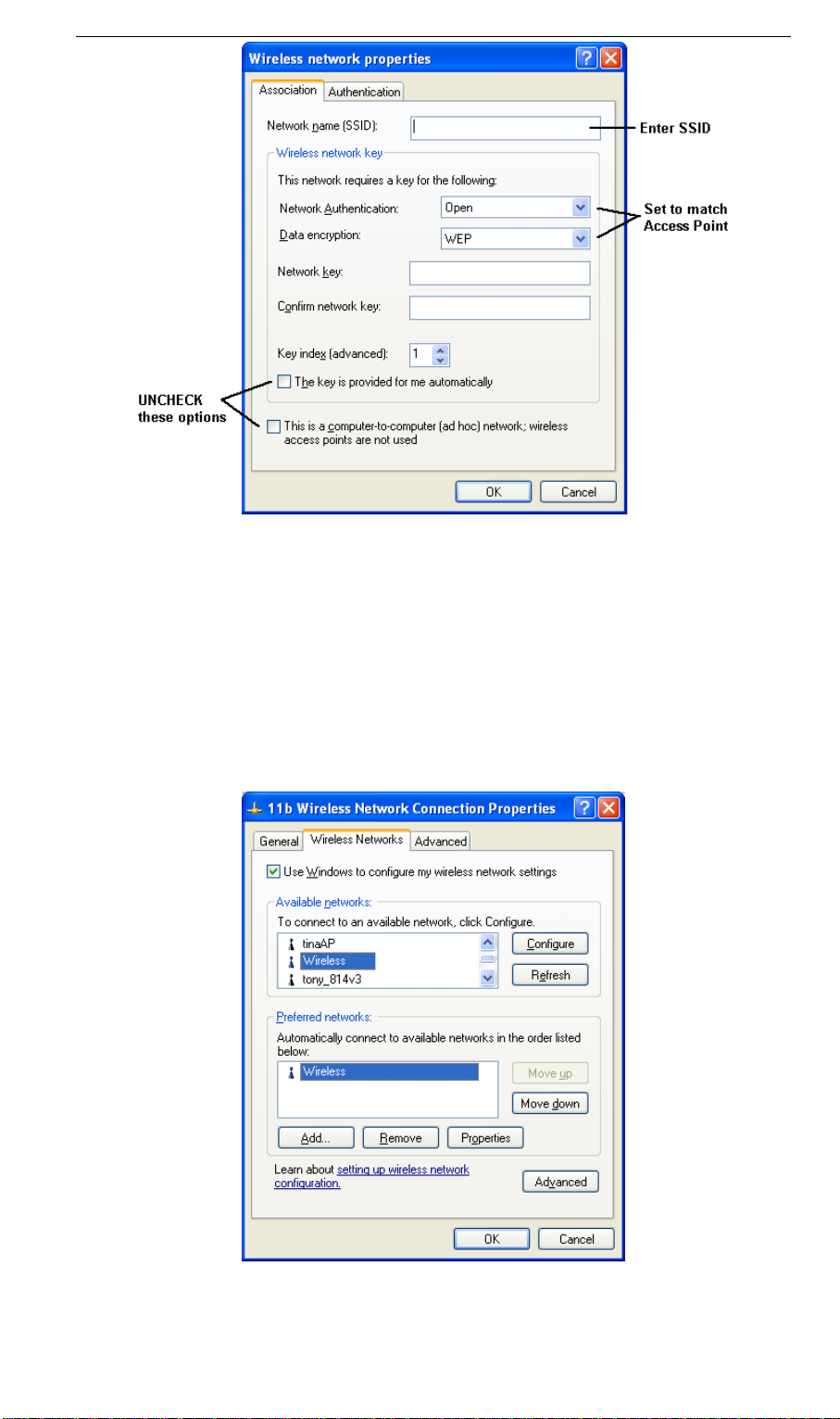
3. Configure this screen as follows:
• Enter the correct SSID, as used on the Wireless ADSL Router. Remember the SSID is
case-sensitive, so be sure to match the case, not just the spelling.
• Set Network Authentication and Data Encryp tion to match the Wireless ADSL Router.
• If using data encryption (WEP or WPA-PSK), enter the key used on the Wireless
ADSL Router. See the preceding sections for details of WEP and WPA-PSK.
• Uncheck the options The key is provided for me automatically and This is a comput-
er-to-computer (ad hoc) network.
• Click OK to save and exit.
4. This wireless network will then be listed in Preferred Networks on the screen below.
5. Click OK to establish a connection to the Wireless ADSL Router.
26

Installation
Requirements
• Network cables. Use standard 10/100BaseT network (UTP) cables with RJ45 connectors.
• TCP/IP protocol must be installed on all PCs.
• For Internet Access, an Internet Access account with an ISP, and a DSL connection.
• To use the Wireless Access Point, all Wireless devices must be compliant with the IEEE
802.11g, IEEE 802.11b or IEEE 802.11n Draft specifications.
Procedure
1. Choose an Installation Site
Select a suitable place on the network to install the Wireless ADSL Router.
For best Wireless reception and performance, the Wireless
ADSL Router should be positioned in a central location with
minimum obstructions between the Wireless ADSL Router
and the PCs.
Also, if using multiple Access Points, adjacent Access
Points should use different Channels.
2. Connect LAN Cables
Use standard LAN cables to connect PCs to the Switching Hub ports on the Wireless
ADSL Router. Both 10BaseT and 100BaseT connections can be used simultaneously.
If required, connect any port to a normal port on another Hub, using a standard LAN cable.
3. Connect ADSL Cable
Connect the supplied ADSL cable from to the ADSL port on the Wireless ADSL Router
(the RJ11 connector) to the ADSL terminator provided by your phone company.
27

4. Power Up
Connect the supplied power adapter to the Wireless ADSL Router. Use only the power
adapter provided. Using a different one may cause hardware damage.
5. Check the LEDs
• The Power LED should be ON.
• For each LAN (PC) connection, one of the LAN LEDs should be ON (provided the PC is
also ON.)
• The WLAN LED should be ON
• The ADSL LED should be ON if ADSL line is connected.
• The Internet LED may be OFF. After configuration, it should come ON.
For more information, refer to Front-mounted LEDs in page 4.
28

Setup
Overview
This chapter describes the setup procedure for:
• Internet Access
• LAN configuration
• Wireless setup
• Assigning a Password to protect the configuration data.
PCs on your local LAN may also require configuration. For details, see Chapter 4 - PC Configuration.
Other configuration may also be required, depending on which features and functions of the
Wireless ADSL Router you wish to use. Use the table below to locate detailed instructions for
the required functions.
29

Configuration Program
The Wireless ADSL Router contains an HTTP server. This enables you to connect to it, and
configure it, using your Web Browser. Your Browser must support JavaScript.
The configuration program has been tested on the following browsers:
• Netscape 7.1 or later.
• Mozilla 1.6 or later
• Internet Explorer V5.5 or later
Preparation
Before attempting to configure the Wireless ADSL Router, please ensure that:
• Your PC can establish a physical connection to the Wireless ADSL Router. The PC and
the Wireless ADSL Router must be directly connected (using the Hub ports on the Wireless ADSL Router) or on the same LAN segment.
• The Wireless ADSL Router must be installed and powered ON.
• If the Wireless ADSL Router's default IP Address (192.168.10.1) is already used by
another device, the other device must be turned OFF until the Wireless ADSL Router is
allocated a new IP Address during configuration.
Using your Web Browser
To establish a connection from your PC to the TEW-657BRM:
6. After installing the TEW-657BRM in your LAN, start your PC. If your PC is already
running, restart it.
7. Start your WEB browser.
8. In the Address box, enter "HTTP://" and the IP Address of the TEW-657BRM, as in this
example, which uses the Wireless ADSL Router's default IP Address:
HTTP://192.168.10.1
9. When prompted for the User name and Password, enter values as follows:
• User name admin
• Password admin
30

If you can't connect
If the Wireless ADSL Router does not respond, check the following:
• The Wireless ADSL Router is properly installed, LAN connection is OK, and
it is powered ON. You can test the connection by using the "Ping" command:
• Open the MS-DOS window or command prompt window.
• Enter the command:
ping 192.168.10.1
If no response is received, either the connection is not working, or your
PC's IP address is not compatible with the Wireless ADSL Router's IP
Address. (See next item.)
• If your PC is using a fixed IP Address, its IP Address must be within the range
192.168.10.2 to 192.168.10.254 to be compatible with the Wireless ADSL
Router's default IP Address of 192.168.10.1. Also, the Network Mask must be
set to 255.255.255.0. See Chapter 4 - PC Configuration for details on checking your PC's TCP/IP settings.
• Ensure that your PC and the Wireless ADSL Router are on the same network
segment. (If you don't have a router, this must be the case.)
• Ensure you are using the wired LAN interface. The Wireless interface can only
be used if its configuration matches your PC's wireless settings.
Setup Wizard
The first time you connect to the Wireless ADSL Router, you should run the Setup Wizard to
configure the ADSL and Internet Connection.
1. Click the Setup Wizard link on the main menu and click “Next”.
2. On the below screen, select Auto-detect or Manual Selection, then click "Next"

3. If Manual Selection is selected, you will see the VC 1 screen shown below. Enter the VPI
and VCI values provided by your ISP, then click "Next".
4. On the Internet Access Screen, shown above, select the correct connection type, as used
by your ISP. Click "Next" and complete the configuration for your connection method.
• You need the data supplied by your ISP. Your ISP's data will also have the DSL Mul-
tiplexing Method ( LLC or VC )
• The common connection types are explained in the following table..
Connection Type Details ISP Data required
Dynamic
IP Address
Your IP Address is allocated
automatically, when you connect to you ISP.
Often, none.
Some ISP's may require you to
use a particular Hostname or
Domain name, or MAC (physical)
address.
Static (Fixed)
IP Address
Your ISP allocates a permanent
IP Address to you.
Usually, the connection is
"Always on".
IP Address allocated to you, and
related information, such as
Network Mask, Gateway IP
address, and DNS address.
32

PPPoE, PPPoA You connect to the ISP only
when required. The IP address
is usually allocated automatically.
a) User name and password are
always required.
b) If using a Static (Fixed) IP
address, you need the IP address
and related information (Network
Mask, Gateway IP address, and
DNS address)
IPoA
(IP over ATM)
Normally, the connection is
"Always on".
IP Address allocated to you, and
related information, such as
Network Mask, Gateway IP
address, and DNS address.
5. Step through the Wizard until finished.
6. On the final screen of the Wizard, run the test and check that an Internet connection can be
established.
7. If the connection test fails:
• Check all connections, and the front panel LEDs.
• Check that you have entered all data correctly.

Home Screen
After finishing the Setup Wizard, you will see the Home screen. When you connect in future,
you will see this screen when you connect. An example screen is shown below.
Main Menu
The main menu, on the left, contains links to the most-commonly used screen. To see the links
to the other available screens, click "Advanced" or "Administration".
The main menu also contains two (2) buttons:
• Log Out - When finished, you should click this button to logout.
Navigation & Data Input
• Use the menu bar on the left of the screen, and the "Back" button on your Browser, for
navigation.
• Changing to another screen without clicking "Save" does NOT save any changes you may
have made. You must "Save" before changing screens or your data will be ignored.
On each screen, clicking the "Help" button will
display help for that screen.
34

LAN Screen
Use the LAN link on the main menu to reach the LAN screen. An example screen is shown
below.
Data - LAN Screen
TCP/IP
IP Address
Subnet Mask
DHCP Server
IP address for the Wireless ADSL Router, as seen from the local LAN.
Use the default value unless the address is already in use or your LAN
is using a different IP address range. In the latter case, enter an unused
IP Address from within the range used by your LAN.
The default value 255.255.255.0 is standard for small (class "C")
networks. For other networks, use the Subnet Mask for the LAN
segment to which the Wireless ADSL Router is attached (the same
value as the PCs on that LAN segment).
• If Enabled, the Wireless ADSL Router will allocate IP Addresses
to PCs (DHCP clients) on your LAN when they start up. The default (and recommended) value is Enabled.
• If you are already using a DHCP Server, this setting must be
Disabled, and the existing DHCP server must be re-configured to
treat the Wireless ADSL Router as the default Gateway. See the
following section for further details.
• The Start IP Address, Finish IP Address and Lease Time fields
set the values used by the DHCP server when allocating IP Addresses to DHCP clients. This range also determines the number of
DHCP clients supported.
See the following section for further details on using DHCP.
DHCP
What DHCP Does
A DHCP (Dynamic Host Configuration Protocol) Server allocates a valid IP address to a
DHCP Client (PC or device) upon request.
• The client request is made when the client device starts up (boots).

• The DHCP Server provides the Gateway and DNS addresses to the client, as well as
allocating an IP Address.
• The Wireless ADSL Router can act as a DHCP server.
• Windows 95/98/ME and other non-Server versions of Windows will act as a DHCP client.
This is the default Windows setting for the TCP/IP network protocol. However, Windows
uses the term Obtain an IP Address automatically instead of "DHCP Client".
• You must NOT have two (2) or more DHCP Servers on the same LAN segment. (If your
LAN does not have other Routers, this means there must only be one (1) DHCP Server on
your LAN.)
Using the Wireless ADSL Router's DHCP Server
This is the default setting. The DHCP Server settings are on the LAN screen. On this screen,
you can:
• Enable or Disable the Wireless ADSL Router's DHCP Server function.
• Set the range of IP Addresses allocated to PCs by the DHCP Server function.
You can assign Fixed IP Addresses to some devices
while using DHCP, provided that the Fixed IP Addresses
are NOT within the range used by the DHCP Server.
Using another DHCP Server
You can only use one (1) DHCP Server per LAN segment. If you wish to use another DHCP
Server, rather than the Wireless ADSL Router's, the following procedure is required.
• Disable the DHCP Server feature in the Wireless ADSL Router. This setting is on the
LAN screen.
• Configure the DHCP Server to provide the Wireless ADSL Router's IP Address as the
Default Gateway.
To Configure your PCs to use DHCP
This is the default setting for TCP/IP for all non-Server versions of Windows.
See Chapter 4 - Client Configuration for the procedure to check these settings.
36

Wireless Screen
The Wireless ADSL Router's settings must match the other Wireless stations.
Note that the Wireless ADSL Router will automatically accept both 802.11b and 802.11g
connections, and no configuration is required for this feature.
To change the Wireless ADSL Router's default settings for the Wireless Access Point feature,
use the Wireless link on the main menu to reach the Wireless screen. An example screen is
shown below.
Data - Wireless Screen
Region
Region
Select the correct domain for your location. It is your responsibility to
ensure:
• That the Wireless ADSL Router is only used in domains for which
is licensed.
• That you select the correct domain, so that only the legal channels
for that domain can be selected.

Multi SSID
SSID
SSID 1/2
Broadcast SSID
Isolation within
SSID
Security Setting
With Multiple SSIDs, you can have 2 SSIDs on one AP. For example,
a Guest SSID without encryption for visitors to have Internet access
only, and a Admin SSID with encryption for private use to secure your
company resources.
Select the desired SSID from the list to configure.
This is also called the "Network Name".
• If using an ESS (Extended Service Set, with multiple access
points) this ID is called an ESSID (Extended Service Set Identifier).
• To communicate, all Wireless stations should use the same
SSID/ESSID.
If enabled, the Wireless ADSL Router will broadcast its SSID. This
allows PCs and other wireless stations to detect this Access Point and
use the correct SSID.
If disabled, PC users will have to manually enter the SSID and other
details of the wireless interface before they can connect to this Access
Point.
If Enabled, devices that have the same SSID will not be able to see
each other.
The current Wireless security is displayed. The default value is Disabled.
Configure SSID
1/2 Button
Options
802.11 Mode
Channel NO.
Isolation
between SSID
WMM Support
Click this button to access the Wireless security sub-screen, and view
or change the settings. See the following section for details.
Select the desired mode:
• Off - Wireless is disabled.
• B only - Only 802.11b connections are available. 802.11g Wire-
less Stations will only be able to use the Wireless Router if they
are fully backward-compatible with the 802.11b standard.
• G only - Only 802.11g Wireless stations can use the Wireless
Router.
• 11b/g/n - 802.11.g, 802.11b and 802.11n Wireless stations can use
the Wireless Broadband Router.
Select the Channel you wish to use on your Wireless LAN.
• If you experience interference (shown by lost connections and/or
slow data transfers) you may need to experiment with different
channels to see which is the best.
• If using multiple Access Points, adjacent Access Points should use
different Channels to reduce interference.
If Enabled, devices that have the different SSIDs will not be able to
communicate with each other.
Enable or disable this feature as required.
Bandwidth
Select the desired bandwidth from the list.
38

MAC Address Filter
Allow access
by …
Set Stations
Button
WiFi Protect Setup
Enable WPS
AP PIN Code
Input Client PIN
Code
WDS
Use this feature to determine which Wireless stations can use the
Access Point. The options are:
• All Wireless Stations - All wireless stations can use the access
point, provided they have the correct SSID and security settings.
• Trusted Wireless stations only - Only wireless stations you
designate as "Trusted" can use the Access Point, even if they have
the correct SSID and security settings.
This feature uses the MAC address to identify Wireless stations.
The MAC address is a low-level network identifier which is
unique to each PC or network device.
To define the trusted wireless stations, use the "Set Stations" button.
Click this button to manage the trusted PC database.
Enable this if you want to use Wireless WPS function.
Use the default displayed value or click the Regenerate button to have
the new pin code in the field.
Enter the client’s PIN code in the field and click OK to add the client
device.
Enable WDS
MAC Address
List
This feature allows you to make a completely wireless network by
using multiple access points without connecting them with a wire
LAN.
In order to make the WDS working successfully, the access point must
use the same channel, SSID, as well as the wireless encryption method.
Enter the MAC address(es) of the AP(s) into the fields to allow the
following access points to be connected to the wireless router.

Wireless Security
This screen is accessed by clicking the "Configure SSID" button on the Wireless screen. There
are 6 options for Wireless security:
• Disabled - no data encryption is used.
• WEP - data is encrypted using the WEP standard.
• WPA-PSK - data is encrypted using the WPA-PSK standard. This is a later standard than
WEP, and provides much better security than WEP. If all your Wireless stations support
WPA-PSK, you should use WPA-PSK rather than WEP.
• WPA2-PSK - This is a further development of WPA-PSK, and offers even greater securi-
ty, using the AES (Advanced Encryption Standard) method of encryption.
• WPA-PSK and WPA2-PSK - This method, sometimes called "Mixed Mode", allows
clients to use EITHER WPA-PSK OR WPA2-PSK.
• 802.1x - This uses the 802.1x standard for client authentication, and WEP for data encryp-
tion.
If this option is selected:
• This Access Point must have a "client login" on the Radius Server.
• Each user must have a "user login" on the Radius Server.
• Each user's wireless client must support 802.1x and provide the login data when re-
quired.
• All data transmission is encrypted using the WEP standard. You only have to select
the WEP key size; the WEP key is automatically generated.
WEP Wireless Security
Data - WEP Screen
WEP Data Encryption
Authentication
Type
WEP Data
Encryption
Normally, this should be left at the default value of "Automatic". If
changed to "Open System" or "Shared Key", ensure that your Wireless
Stations use the same setting.
Select the desired option, and ensure the Wireless Stations use the
same setting.
• 64 Bit - data is encrypted, using the default key, before being
transmitted. You must enter at least the default key. For 64 Bit Encryption, the key size is 10 chars in HEX (0~9 and A~F).
40

• 128 Bit - data is encrypted, using the default key, before being
transmitted. You must enter at least the default key. For 128 Bit
Encryption, the key size is 26 chars in HEX (0~9 and A~F).
Default Key
Key Value Enter the key value or values you wish to use. The Default Key is
Passphrase
Select the key you wish to be the default. Transmitted data is
ALWAYS encrypted using the Default Key; the other Keys are for
decryption only.
You must enter a Key Value for the Default Key.
required, the other keys are optional. Other stations must have the
same key.
If desired, you can generate a key from a phrase, instead of entering
the key value directly. Enter the desired phrase, and click the "Generate Keys" button.
WPA-PSK Wireless Security
Data - WPA-PSK Screen
Security
System
PSK
WPA Encryption
WPA-PSK
Like WEP, data is encrypted before transmission. WPA is more
secure than WEP, and should be used if possible. WPA-PSK is the
version of WPA, which does NOT require a Radius Server on your
LAN.
Enter the PSK (network key). Data is encrypted using a key derived
from the network key. Other Wireless Stations must use the same
network key. The PSK must be from 8 to 63 characters in length.
The WPA-PSK standard allows different encryption methods to be
used. Select the desired option. Wireless Stations must use the same
encryption method.

Security Settings - WPA2-PSK
This is a further development of WPA-PSK, and offers even greater security, using the AES
(Advanced Encryption Standard) method of encryption.
Figure 1: WPA2-PSK Wireless Security Screen
Data - WPA2-PSK Screen
WPA2-PSK
PSK
Encryption
Enter the key value. Data is encrypted using a 256Bit key derived
from this key. Other Wireless Stations must use the same key.
The WPA2-PSK standard allows different encryption methods to
be used. Select the desired option. Wireless Stations must use the
same encryption method.
42

Security Settings - Mixed WPA-PSK/WPA2-PSK
This method, sometimes called "Mixed Mode", allows clients to use EITHER WPA-PSK OR
WPA2-PSK.
Data - WPA2-PSK Screen
WPA2-PSK
PSK
Encryption
Enter the key value. Data is encrypted using a 256Bit key derived
from this key. Other Wireless Stations must use the same key.
This standard allows different encryption methods to be used.
Select the desired option. Wireless Stations must use the same
encryption method.

Security Settings - 802.1x
This uses the 802.1x standard for client authentication, and WEP for data encryption. If this
option is selected:
• This Access Point must have a "client login" on the Radius Server.
• Each user must have a "user login" on the Radius Server. Normally, a Certificate is used to
authenticate each user. See Chapter4 for details of user configuration.
• Each user's wireless client must support 802.1x.
• All data transmission is encrypted using the WEP standard. You only have to select the
WEP key size; the WEP key is automatically generated.
Data - 802.1x Screen
Server Address
Radius Port
Shared Key
Encryption
Enter the server address here.
Enter the port number used for connections to the Radius Server.
Enter the shared key. Data is encrypted using a key derived from the
network key. Other Wireless Stations must use the same key. The
key must be from 8 to 63 characters in length.
The encryption method is TKIP. Wireless Stations must also use
TKIP.
44

Trusted Wireless Stations
This feature can be used to prevent unknown Wireless stations from using the Access Point.
This list has no effect unless the setting Allow access by trusted stations only is enabled.
To change the list of trusted wireless stations, use the Modify List button on the Access Control
screen. You will see a screen like the sample below.
Data - Trusted Wireless Stations
Trusted Wireless
Stations
Other Wireless
Stations
Name
Address
Buttons
<<
>>
This lists any Wireless Stations which you have designated as
“Trusted”.
This list any Wireless Stations detected by the Access Point, which
you have not designated as "Trusted".
The name assigned to the Trusted Wireless Station. Use this when
adding or editing a Trusted Station.
The MAC (physical) address of the Trusted Wireless Station. Use
this when adding or editing a Trusted Station.
Add a Trusted Wireless Station to the list (move from the "Other
Stations" list).
• Select an entry (or entries) in the "Other Stations" list, and
click the " << " button.
• Enter the Address (MAC or physical address) of the wireless
station, and click the "Add " button.
Delete a Trusted Wireless Station from the list (move to the "Other
Stations" list).
• Select an entry (or entries) in the "Trusted Stations" list.
• Click the " >> " button.

Edit
Add (Update)
Clear
Use this to change an existing entry in the "Trusted Stations" list:
1. Select the Station in the Trusted Station list.
2. Click the Edit button. The address will be copied to the "Ad -
dress" field, and the Add button will change to Update.
3. Edit the address (MAC or physical address) as required.
4. Click Update to save your changes.
To add a Trusted Station which is not in the "Other Wireless
Stations" list, enter the required data and click this button.
When editing an existing Wireless Station, th is button will change
from Add to Update.
Clear the Name and Address fields.
46

Password Screen
The password screen allows you to assign a password to the Wireless ADSL Router.
Old Password
Enter the existing password in this field.
New password
Verify password
You will be prompted for the password when you re-connect. The "User Name" is always
admin and enter the new password applied.
Enter the new password here.
Re-enter the new password here.

Mode Screen
Use this screen to change the mode between Router mode and Modem (Bridge) mode.
Select the desired option, and click "Save".
Router
Modem
Both the ADSL Modem and the Router features are operational. In this
mode, this device can provide shared Internet Access to all your LAN users.
Also, by default, it acts a DHCP Server, providing an IP address and related
information to all Wireless and LAN users.
Only the ADSL Modem component is operational.
• All Router features are disabled. This device is "transparent" - it does
not perform any operations or make any changes to the network traffic
passing through it.
• You need to have a DHCP Server on your LAN to provide IP addresses
to the Wireless clients using this Access Point.
• All traffic received on either the Wireless or LAN interface will be sent
over the ADSL connection.
Notes:
• Generally, you should NOT use modem mode. Only select this mode if you are sure this is
what you want.
• After changing the mode, this device will restart, which will take a few seconds. The
menu will also be changed, depending on the mode you are in.
• The Wireless Access Point can function in either Router or Modem mode. But generally it
is not a good idea to combine a Modem with an Access Point, because all data received
from the wireless stations will be sent over the modem connection. (Since the modem is
transparent, it does not examine the traffic to determine whether the traffic is for the LAN
or the WAN.)
• For details on using Modem Mode, see Chapter 8.
48

Operation and Status
Operation - Router Mode
Once both the Wireless ADSL Router and the PCs are configured, operation is automatic.
However, there are some situations where additional Internet configuration may be required.
Refer to Chapter 6 - Advanced Features for further details.
Status Screen
Use the Status link on the main menu to view this screen.
Data - Status Screen
ADSL
Modem Status
DownStream
Connection Speed
UpStream
Connection Speed
This indicates the status of the ADSL modem component.
Displays the speed for the DownStream Connection.
If connected, displays the speed for the Up Stream (upload)
ADSL Connection.

Internet
Connection Method
Connection Status
Internet IP Address
WAN MAC Address
Connection Details
LAN
Displays the current connection method, as set in the Setup
Wizard.
This indicates the current status of the Internet Connection
• Active - Connection exists
• Idle - No current connection, but no error has been detected.
This condition normally arises when an idle connection is automatically terminated.
• Failed - The connection was terminated abnormally. This
could be caused by Modem failure, or the loss of the connection to the ISP's server.
If there is an error, you can click the "Connection Details" button
to find out more information.
This IP Address is allocated by the ISP (Internet Service Provider). If using a dynamic IP address, and no connection currently
exists, this information is unavailable.
It displays the MAC address for the WAN.
Click this button to open a sub-window and view a detailed
description of the current connection. Depending on the type of
connection, a "log" may also be available.
IP Address
Network Mask
DHCP Server
MAC Address
Wireless
SSID 1
MAC Address
SSID 2
MAC Address
Region
Channel
Wireless AP
Broadcast Name
The IP Address of the Wireless ADSL Router.
The Network Mask (Subnet Mask) for the IP Address above.
This shows the status of the DHCP Server function. The value
will be "Enabled" or "Disabled".
This shows the MAC Address for the Wireless ADSL Router, as
seen on the LAN interface.
It displays the name of the SSID 1.
It displays the MAC address of the SSID 1.
It displays the name of the SSID 2.
It displays the MAC address of the SSID 2.
The current region, as set on the Wireless screen.
This shows the Channel currently used, as set on the Wireless
screen.
This indicates whether or not the Wireless Access Point feature is
enabled.
This indicates whether or not the SSID is Broadcast. This setting
is on the Wireless screen.
System
Device Name
The current name of the Router. This name is also the "hostname"
for users with an "@Home" type connection.
50

Firmware Version
Buttons
Connection Details
Attached Devices
Refresh Screen
The version of the current firmware installed.
Click this button to open a sub-window and view a detailed
description of the current connection.
This will open a sub-window, showing all LAN and Wireless
devices currently on the network.
Update the data displayed on screen.

Connection Status - PPPoE & PPPoA
If using PPPoE (PPP over Ethernet) or PPPoA (PPP over ATM), a screen like the following
example will be displayed when the "Connection Details" button is clicked.
Data - PPPoE/PPPoA Screen
Connection Time
PPPoE Link Status
Negotiation
IP Address
Network Mask
Buttons
Connect
Disconnect
Close
This indicates how long the current connection has been established.
This indicates whether or not the connection is currently established.
• If the connection does not exist, the "Connect" button can be
used to establish a connection.
• If the connection currently exists, the "Disconnect" button
can be used to break the connection.
This indicates the status of the PPPoE Server login.
The IP Address of this device, as seen by Internet users. This
address is allocated by your ISP (Internet Service Provider).
The Network Mask associated with the IP Address above.
If not connected, establish a connection to your ISP.
If connected to your ISP, hang up the connection.
Close this window.
52

Connection Details - Dynamic IP Address
If your access method is "Direct" (no login), with a Dynamic IP address, a screen like the
following example will be displayed when the "Connection Details" button is clicked.
Data - Dynamic IP address
Internet
IP Address
Network Mask
Default Gateway
DHCP Server
DNS Server
Lease Obtained
Lease Expires
Buttons
Release
Renew
Close
The current IP Address of this device, as seen by Internet users. This
address is allocated by your ISP (Internet Service Provider).
The Network Mask associated with the IP Address above.
The IP address of the remote Gateway or Router associated with the
IP Address above.
The IP address of your ISP's DHCP Server.
The IP address of the Domain Name Server which is currently used.
This indicates when the current IP address was obtained, and how
long before this IP address allocation (the DCHP lease) expires.
If an IP Address has been allocated to the Wireless ADSL Router (by
the ISP's DHCP Server, clicking the "Release" button will break the
connection and release the IP Address.
If the ISP's DHCP Server has NOT allocated an IP Address for the
Wireless ADSL Router, clicking the "Renew" button will attempt to
re-establish the connection and obtain an IP Address from the ISP's
DHCP Server.
Close this window.

Connection Details - Fixed IP Address
If your access method is "Direct" (no login), with a fixed IP address, a screen like the following example will be displayed when the "Connection Details" button is clicked.
Data - Fixed IP address Screen
Internet
IP Address
Network Mask
Default Gateway
DNS Server
The IP Address of this device, as seen by Internet users. This address
is allocated by your ISP (Internet Service Provider).
The Network Mask associated with the IP Address above.
The IP Address of the remote Gateway or Router associated with the
IP Address above.
The IP Address of the Domain Name Server which is currently used.
54

Advanced Features
Overview
The following advanced features are provided:
• Internet:
• DMZ
• URL filter
• Access Control
• Dynamic DNS
• Options
• Schedule
• Port Trigger
• Port Forward
• Port Range Forward
• QoS
Internet
This screen provides access to the DMZ and URL Filter features.
DMZ
This feature, if enabled, allows the DMZ computer on your LAN to be exposed to all users on
the Internet.
• This allows almost any application to be used on the "DMZ PC".
• The "DMZ PC" will receive all "Unknown" connections and data.
55

• If the DMZ feature is enabled, you must enter the IP address of the PC to be used as the
"DMZ PC".
The "DMZ PC" is effectively outside the Firewall, making it more vulnerable to attacks. For this reason, you
should only enable the DMZ feature when required.
URL Filter
If you want to limit access to certain sites on the Internet, you can use this feature. The URL
filter will check each Web site access. If the address, or part of the address, is included in the
block site list, access will be denied.
On the Advanced Internet screen, select the desired setting:
• Disable - disable this feature.
• Block Always - allow blocking all of the time, independent of the Schedule page.
• Block By Schedule - block according to the settings on the Schedule page.
Click the Configure URL Filter button to open the URL Filter screen, allowing you to create
or modify the filter strings which determine which sites will be blocked.
The URL Filter screen is displayed when the Configure URL Filter button on the Internet
screen is clicked.
Data - URL Filter Screen
Current Filter Strings
Current Filter
Strings
The list contains the current list of items to block.
• To add to the list, use the "Add" option below.
• To delete an entry, select it and click Delete button.
• To delete all entries, click the Delete All button.
56

Add Filter String
Trusted PC
Allow this PC..
Trusted PC
To add to the current list, type the word or domain name you want to
block into the field provided, then click the Add button.
Filter strings should be as specific as possible. Otherwise, you may
block access to many more sites than intended.
Enable this to allow one computer to have unrestricted access to the
Internet. For this PC, the URL filter will be ignored.
If enabled, you must select the PC to be the trusted PC.
Select the PC to be the Trusted PC.

Access Control
This feature is accessed by the Access Control link on the Advanced menu.
Overview
The Access Control feature allows administrators to restrict the level of Internet Access available to PCs on your LAN. With the default settings, everyone has unrestricted Internet access.
Restrictions are imposed by blocking "Services", or types of
connections. All common Services are pre-defined.
If required, you can also define your own Services.
Access Control Screen
To view this screen, select the Access Control link on the Advanced menu.
Data - Access Control Screen
Internet Access
Access Control
Select the desired options for the current group:
• Disable - Nothing is blocked. Use this to create the least
restrictive group.
• Block all Internet access - All traffic via the WAN port is
blocked. Use this to create the most restrictive group.
• Block selected Services - You can select which Services are to
block. Use this to gain fine control over the Internet access for
a group.
58

Blocked Services
This lists all defined Services. Select the Services you wish to
block. To select multiple services, hold the CTRL key while
selecting. (On the Macintosh, hold the SHIFT key rather than
CTRL.)
Schedule
If Internet access is being blocked, you can choose to apply the
blocking only during scheduled times. (If access is not blocked, no
Scheduling is possible, and this setting has no effect.)
Trusted PCs
Click to Enable
Trusted PC
"Set Trusted PCs"
Button
If enabled, restrictions set on this screen do not apply to Trusted
PCs.
Click this button to add or remove PCs of the Trusted PCs.
See the following section for details of the Trusted PCs screen.
Trusted PC Screen
This screen is displayed when the Set Trusted PCs button on the Access Control screen is
clicked.
Use this screen to add or remove PCs from the current group.
• The "Del >>" button will remove the selected PC (in the Trusted PCs list) from the current
group.
• The "<< Add" button will add the selected PC (in the Other PCs list) to the Trusted PCs
group.

Dynamic DNS (Domain Name Server)
This free service is very useful when combined with the Virtual Server feature. It allows
Internet users to connect to your Virtual Servers using a URL, rather than an IP Address.
This also solves the problem of having a dynamic IP address. With a dynamic IP address, your
IP address may change whenever you connect, which makes it difficult to connect to you.
DDNS Services work as follows:
1. You must register for the service at one of the listed DDNS Service providers.
2. After registration, use the Service provider's normal procedure to obtain your desired
Domain name.
3. Enter your DDNS data on the Wireless ADSL Router's DDNS screen, and enable the
DDNS feature.
4. The Wireless ADSL Router will then automatically ensure that your current IP Address is
recorded at the DDNS service provider's Domain Name Server.
5. From the Internet, users will be able to connect to your Virtual Servers (or DMZ PC)
using your Domain name, as shown on this screen.
Dynamic DNS Screen
Select Advanced on the main menu, then Dynamic DNS, to see a screen like the following:
Data - Dynamic DNS Screen
DDNS Service
Use a Dynamic
DNS Service
Use this to enable or disable the DDNS feature as required.
Service Provider
Web Site
DDNS Data
Host Name
Select the desired DDNS Service provider.
Click this button to open a new window and connect to the Web site
of the selected DDNS service provider.
Enter the domain name allocated to you by the DDNS Service. If you
60

have more than one name, enter the name you wish to use.
User Name
Password
DDNS Status
Enter your Username for the DDNS Service. (TZO.com uses your Email address.)
Enter your current password for the DDNS Service. (TZO.com calls
this a key.)
• This message is returned by the DDNS Server.
• Normally, this message should be "Update successful"
• If the message indicates some problem, you need to connect to
the DDNS Service provider and correct this problem.

Options
This screen allows advanced users to enter or change a number of settings. For normal operation, there is no need to use this screen or change any settings.
An example Options screen is shown below.
Data - Options Screen
Internet
Respond to Ping
MTU Size
UPnP
UPnP
Advertisement
Period
• If checked, the Wireless Router will respond to Ping (ICMP)
packets received from the Internet.
• If not checked, Ping (ICMP) packets from the Internet will be
ignored. Disabling this option provides a slight increase in security.
Enter a value between 600 and 3000.
Note: MTU (Maximum Transmission Unit) size should only be
changed if advised to do so by Technical Support.
• UPnP (Universal Plug and Play) allows automatic discovery and
configuration of equipment attached to your LAN. UPnP is by
supported Windows ME, XP, or later.
• If Enabled, this device will be visible via UPnP.
• If Disabled, this device will not be visible via UPnP.
Enter the desired value, in minutes. The valid range is from 1 to 1440.
Advertisement
Time to Live
Enter the desired value, in hops. The valid range is from 1 to 255.
62

Schedule
This Schedule can be used for the Firewall Rules and the URL filter.
Data - Schedule Screen
Schedule
Day
Session 1
Session 2
Start
Finish
Local Time
Time Zone
Adjust for Daylight Savings Time
Use this NTP
Server
Each day of the week can scheduled independently.
Two (2) separate sessions or periods can be defined. Session 2 can
be left blank if not required.
Enter the start using a 24 hr clock.
Enter the finish time using a 24 hr clock.
In order to display your local time correctly, you must select your
"Time Zone" from the list.
If your region uses Daylight Savings Time, you must manually
check "Adjust for Daylight Savings Time" at the beginning of the
adjustment period, and uncheck it at the end of the Daylight Savings
period.
If you prefer to use a particular NTP server as the primary NTP
server, check the checkbox "Use this NTP Server" and enter the
Server's IP address in the fields provided.
If this setting is not enabled, the default NTP Servers are used.
Current Time
This displays the current time on the Wireless ADSL Router, at the
time the page is loaded.

Port Trigger
If you use Internet applications which use non-standard connections or port numbers, you may
find that they do not function correctly because they are blocked by the Wireless ADSL
Router's firewall. In this case, you can define the application as a "Port Trigger".
The Port Trigger screen can be reached by clicking the Port Trigger on the screen.
You can then define your Port Trigger. You will need detailed information about the applica-
tion; this is normally available from the supplier of the application.
Also, note that the terms "Incoming" and "Outgoing" on this screen refer to traffic from the
client (PC) viewpoint
Data - Port Trigger Screen
Port Trigger
Enable
Name
Outgoing
Ports
Use this to Enable or Disable this Special Application as required.
Enter a descriptive name to identify this Special Application.
• Type - Select the protocol (TCP or UDP) used when you send
data to the remote system or service.
• Start - Enter the beginning of the range of port numbers used
by the application server, for data you send to it. If the application uses a single port number, enter it in both the "Start" and
"Finish" fields.
• Finish - Enter the end of the range of port numbers used by the
application server, for data you send to it. If the application
uses a single port number, enter it in both the "Start" and
"Finish" fields.
64

Incoming
Ports
• Type - Select the protocol (TCP or UDP) used when you
receive data from the special application or service. (Note:
Some applications use different protocols for outgoing and incoming data).
• Start - Enter the beginning of the range of port numbers used
by the application server, for data you receive. If the application uses a single port number, enter it in both the "Start" and
"Finish" fields.
• Finish - Enter the end of the range of port numbers used by the
application server, for data you receive.

Port Forward
This feature allows you to make Servers on your LAN accessible to Internet users. Normally,
Internet users would not be able to access a server on your LAN because:
• Your Server does not have a valid external IP Address.
• Attempts to connect to devices on your LAN are blocked by the firewall in this device.
Data - Single Port Forwarding Screen
Port Forwarding
Application
External Port
Internal Port
Protocol
IP Address
Enabled
Enter the desired application type.
Traffic from the Internet using this port number will be sent to the
Server. This is normally the same as the Internal Port Number. If it
is different, this device will perform a "mapping" or "translation"
function, allowing the server to use a different port to the clients.
Enter the port numbers which the Server software is configured to
use.
Select the protocol (TCP or UDP) used by the Server.
Enter the desired IP address.
Use this to Enable or Disable support for this Server, as required.
66

Port Range Forward
This feature allows you to make Servers on your LAN accessible to Internet users. Normally,
Internet users would not be able to access a server on your LAN because:
Data - Port Range Forwarding Screen
Port Range Forwarding
Application
Start
End
Protocol
IP Address
Enable
Enter the desired application type.
Enter the beginning of the range of port numbers used by the
application server.
Enter the end of the range of port numbers used by the application
server.
Select the protocol (TCP, UDP or Both) used by the Server.
Enter the desired IP address.
Use this to Enable or Disable support for this Server, as required.

QoS
The QoS (Quality of Service) feature allows you specify priorities for different traffic. Lower
priority traffic will be slowed down to allow greater throughput or less delay for high priority
traffic.
An example QoS screen is shown below.
Data - QoS Screen
QoS Setting
QoS Setting
WAN Setting
Downlink
Uplink
Get from WAN
To disable QoS (Quality of Service), keep the default setting, Disable.
To enable QoS (Quality of Service), click Enable and follow these
instructions.
Enter the desired value for the DownStream Connection.
Enter the desired value for the UpStream Connection.
Click this button to get the values for DownStream and UpStream from
WAN.
68

Category
• Normal-Applications:
• Add a New Application (Once selected, please complete the
following setups.)
• Ip/Net: Enter the IP addresses.
• Outbound Rate: Enter the desired rate value.
• Inbound Rate: Enter the desired rate value.
• Priority: Select the desired option (High, Normal, Low)
• Self-Define
• Name. Enter a name for your device.
• Port Range: Enter the values for the desired port range.
• Protocol: Select the desired option.
• Ip/Net: Enter the IP addresses of your device.
• Outbound Rate: Enter the desired rate value.
• Inbound Rate: Enter the desired rate value.
• Priority: Select the option (High, Normal, Low) from the list.
• Special-Applications:
• Add a New Application (Once selected, please complete the
following setups.)
• Ip/Net: Enter the IP addresses.
• Outbound Rate: Enter the desired rate value.
• Inbound Rate: Enter the desired rate value.
• Priority: Select the desired option (High, Normal, Low)
Summary
Priority
Name
Information
The priority of the application.
The Name of this Application or IP Address.
The general Information of this Application or IP Address.

Advanced Administration
Overview
Normally, it is not necessary to use these screens, or change any settings. These screens and
settings are provided to deal with non-standard situations, or to provide additional options for
advanced users.
The available settings and features are:
PC Database
Config File
Logs & Email
Diagnostics
Remote Admin
Routing
Upgrade Firmware
This is the list of PCs shown when you select the "DMZ PC" or a
"Virtual Server". This database is maintained automatically, but
you can add and delete entries for PCs which use a Fixed (Static)
IP Address.
Backup or restore the configuration file for the Wireless ADSL
Router. This file contains all the configuration data.
View or clear all logs, set E-Mailing of log files and alerts.
Perform a Ping or DNS Lookup.
Allow settings to be changed from the Internet.
Only required if your LAN has other Routers or Gateways.
Upgrade the Firmware (software) installed in your Wireless
ADSL Router.
70

PC Database
The PC Database is used whenever you need to select a PC (e.g. for the "DMZ" PC).
• It eliminates the need to enter IP addresses.
• Also, you do not need to use fixed IP addresses on your LAN.
However, if you do use a fixed IP address on some devices on your LAN, you should enter
details of each such device into the PC database, using the PC Database screen.
PC Database Screen
An example PC Database screen is shown below.
• PCs which are "DHCP Clients" are automatically added to the database, and updated as
required.
• By default, non-Server versions of Windows act as "DHCP Clients"; this setting is called
"Obtain an IP Address automatically".
• The Wireless ADSL Router uses the "Hardware Address" to identify each PC, not the
name or IP address. The "Hardware Address" can only change if you change the PC's
network card or adapter.
• This system means you do NOT need to use Fixed (static) IP addresses on your LAN.
However, you can add PCs using Fixed (static) IP Addresses to the PC database
if required.

Data - PC Database Screen
Known PCs
Buttons
Refresh
Advanced
Administration
This lists all current entries. Data displayed is name (IP Address) type.
The "type" indicates whether the PC is connected to the LAN.
Update the data on screen.
View the Advanced version of the PC database screen - PC Database
(Admin). See below for details.
72

PC Database - Advanced
This screen is displayed if the "Advanced Administration" button on the PC Database is
clicked. It provides more control than the standard PC Database screen.
Data - Advanced PC Database
Known PCs
PC Properties
Name
IP Address
MAC Address
This lists all current entries. Data displayed is name (IP Address) type.
The "type" indicates whether the PC is connected to the LAN.
If adding a new PC to the list, enter its name here. It is best if this
matches the PC's "hostname".
Select the appropriate option:
• Automatic - The PC is set to be a DHCP client (Windows: "Ob-
tain an IP address automatically"). The Wireless ADSL Router
will allocate an IP address to this PC when requested to do so. The
IP address could change, but normally won't.
• DCHP Client - Reserved IP Address - Select this if the PC is set
to be a DCHP client, and you wish to guarantee that the Wireless
ADSL Router will always allocate the same IP Address to this PC.
Enter the required IP address.
• Fixed IP Address - Select this if the PC is using a Fixed (Static)
IP address. Enter the IP address allocated to the PC. (The PC itself
must be configured to use this IP address.)
Select the appropriate option
• Automatic discovery - Select this to have the Wireless ADSL
Router contact the PC and find its MAC address. This is only
possible if the PC is connected to the LAN and powered On.
• MAC address is - Enter the MAC address on the PC. The MAC
address is also called the "Hardware Address", "Physical Address", or "Network Adapter Address". The Wireless ADSL
Router uses this to provide a unique identifier for each PC. Because of this, the MAC address can NOT be left blank.

Buttons
Add as New
Entry
Update Selected
PC
Clear Form
Refresh
Standard Screen
Add a new PC to the list, using the data in the "Properties" box.
If "Automatic discovery" (for MAC address) is selected, the PC will be
sent a "ping" to determine its hardware address. This will fail unless
the PC is connected to the LAN, and powered on.
Update (modify) the selected PC, using the data in the "Properties"
box.
Clear the "Properties" box, ready for entering data for a new PC.
Update the data on screen.
Click this to view the standard PC Database screen.
74

Config File
This feature allows you to download the current settings from the Wireless ADSL Router, and
save them to a file on your PC.
You can restore a previously-downloaded configuration file to the Wireless ADSL Router, by
uploading it to the Wireless ADSL Router.
This screen also allows you to set the Wireless ADSL Router back to its factory d efault configuration. Any existing settings will be deleted.
An example Config File screen is shown below.
Data - Config File Screen
Backup Config
Restore Config
Default Config
Use this to download a copy of the current configuration, and store the
file on your PC. Click Backup to start the download.
This allows you to restore a previously-saved configuration file back to
the Wireless ADSL Router.
Click Browse to select the configuration file, then click Restore to
upload the configuration file.
WARNING!
Uploading a configuration file will destroy (overwrite) ALL of the
existing settings.
Clicking the Factory Defaults button will reset the Wireless ADSL
Router to its factory default settings.
WARNING!
This will delete ALL of the existing settings.

Logs
The Logs record various types of activity on the Wireless ADSL Router. This data is useful for
troubleshooting, but enabling all logs will generate a large amount of data and adversely affect
performance.
Since only a limited amount of log data can be stored in the Wireless ADSL Router, log data
can also be E-mailed to your PC. Use the E-mail screen to configure this feature.
Data - Logs Screen
Logs
Current Time
Log Data
Buttons
The current time on the Wireless ADSL Router is displayed.
Current log data is displayed in this panel.
There are three (3) buttons
• Refresh - Update the log data.
• Clear Log - Clear the log, and restart it. This makes new
messages easier to read.
• Send Log - E-mail the log immediately. This is only func-
tional if the E-mail screen has been configured.
76

Logs
Include (Checkboxes)
Syslog
Disable
Broadcast on LAN
Use these checkboxes to determine which events are included in
the log. Checking all options will increase the size of th e log, so it
is good practice to disable any events which are not really required.
• Attempted access to blocked sites - If checked, attempted
Internet accesses which were blocked are logged.
• Connections to the Web-based interface of this Router - If
checked, this will log connections TO this Router, rather than
through this Router to the Internet.
• Router operation - If checked, other Router operations (not
covered by the selections above) will be logged.
• Known DoS attacks and Port Scans - If checked, Denial of
Service attacks, as well as port scans, will be logged.
• Outgoing Connections - If selected, Outgoing Internet
connections are logged.
• Access Control - If enabled, the log will include attempted
outgoing connections which have been blocked by the
"Access Control" feature.
Data is not sent to a Syslog Server.
The Syslog data is broadcast, rather than sent to a specific Syslog
server. Use this if your Syslog Server does not have a fixed IP
address.
Sent to this Syslog
Server
If your Syslog server has a fixed IP address, select this option,
and enter the IP address of your Syslog server.

This screen allows you to E-mail Logs and Alerts. A sample screen is shown below.
Data - E-mail Screen
E-Mail Notification
Turn E-mail
Notification on
Send to this Email address
Outgoing (SMTP)
Mail Server
Mail Sender
Address
My SMTP Mail
Server requires
authentication
User Name
Password
E-mail Alerts
Send E-mail alerts
immediately
Check this box to enable this feature. If enabled, the E-mail address
information (below) must be provided.
Enter the E-mail address the Log is to be sent to. The E-mail will also
show this address as the Sender's address.
Enter the address or IP address of the SMTP (Simple Mail Transport
Protocol) Server you use for outgoing E-mail.
Enter the mail address of the sender. The E-mail will also show this
address as the Sender's address.
To stop spanners, many SMTP mail servers require you to log in to
send mail. In this case, enable this checkbox, and enter the login
information (User name and Password) in the fields below.
If you have enabled "My SMTP Mail Server requires authentication"
above, enter the User Name required to login to your SMTP Server.
If you have enabled "My SMTP Mail Server requires authentication"
above, enter the password required to login to your SMTP Server.
You can choose to have alerts E-mailed to you, by checking the
desired checkboxes. The Broadband ADSL Router can send an
immediate alert when it detects a significant security incident such as
• A known hacker attack is directed at your IP address
• A computer on the Internet scans your IP address for open ports
• Someone on your LAN (Local Area Network) tries to visit a
blocked site.
78

E-mail Logs
Send Logs
Select the desired option for sending the log by E-mail.
• Never (default) - This feature is disabled; Logs are not sent.
• When log is full - The time is not fixed. The log will be sent
when the log is full, which will depend on the volume of traffic.
• Hourly, Daily, Weekly... - The log is sent on the interval
specified.
• If Daily is selected, the log is sent at the time specified.
Select the time of day you wish the E-mail to be sent.
• If Weekly is selected, the log is sent once per week, on the
specified day, at the specified time.
Select the day and the time of day you wish the E-mail to be
sent.
Note:
If the log is full before the time specified to send it, it will be sent
regardless of the day and time specified.

Diagnostics
This screen allows you to perform a "Ping" or a "DNS lookup". These activities can be useful
in solving network problems.
An example Network Diagnostics screen is shown below.
Data - Network Diagnostics Screen
Ping
IP Address
Ping Button
DNS Lookup
Internet name
Lookup Button
Routing
Display
Enter the IP address you wish to ping. The IP address can be on your
LAN, or on the Internet. Note that if the address is on the Internet,
and no connection currently exists, you could get a "Timeout" error.
In that case, wait a few seconds and try again.
After entering the IP address, click this button to start the "Ping "
procedure. The results will be displayed in the Ping Results pane.
Enter the Domain name or URL for which you want a DNS (Domain
Name Server) lookup. Note that if the address in on the Internet, and
no connection currently exists, you could get a "Timeout" error. In
that case, wait a few seconds and try again.
After entering the Domain name/URL, click this button to start the
"DNS Lookup" procedure.
Click this button to display the internal routing table. Th is information can be used by Technical Support and other staff who
understand Routing Tables.
80

Remote Administration
If enabled, this feature allows you to manage the Wireless ADSL Router via the Internet.
Data - Remote Administration Screen
Remote Administration
Enable Remote
Management
Current
IP Address
Port Number
Access Permission
Allow Remote
Access
Check to allow administration/management via the Internet. (To
connect, see below).
If Disabled, this device will ignore Administration connection
attempts from the Internet.
This is the current address you will use when accessing this device
from the Internet. To connect, see details and an example below.
Enter a port number between 1 and 65535. The default for HTTP
(Web) connections is port 80, but using port 80 will prevent the use
of a Web "Virtual Server" on your LAN. So using a different port
number is recommended. The default value is 8080.
The port number must be specified in your Browser when you
connect. See the following section for details.
Select the desired option.
• Everyone - allow access by everyone on the Internet.
• Only This Computer - allow access by only one IP address.
Enter the desired IP address.
• IP Address Range - allow access from a range of IP addresses
on the Internet. Enter a beginning and ending IP address to define the allowed range.
For security, you should restrict access to as few external IP addresses as practical.

To connect from a remote PC via the Internet
1. Ensure your Internet connection is established, and start your Web Browser.
2. In the "Address" bar, enter "HTTP://" followed by the Internet IP Address of the Wireless
ADSL Router. If the port number is not 80, the port number is also required. (After the IP
Address, enter ":" followed by the port number.)
e.g.
HTTP://123.123.123.123:8080
This example assumes the WAN IP Address is 123.123.123.123, and the port number is
8080.
3. You will then be prompted for the login name and password for this device.
82

Routing
Overview
• If you don't have other Routers or Gateways on your LAN, you can ignore the "Routing"
page completely.
• If the Wireless ADSL Router is only acting as a Gateway for the local LAN segment,
ignore the "Routing" page even if your LAN has other Routers.
• If your LAN has a standard Router (e.g. Cisco) on your LAN, and the Wireless ADSL
Router is to act as a Gateway for all LAN segments, enable RIP (Routing Information Protocol) and ignore the Static Routing table.
• If your LAN has other Gateways and Routers, and you wish to control which LAN seg-
ments use each Gateway, do NOT enable RIP (Routing Information Protocol). Configure
the Static Routing table instead. (You also need to configure the other Routers.)
• If using Windows 2000 Data center Server as a software Router, enable RIP on the Wire-
less ADSL Router, and ensure the following Windows 2000 settings are correct:
• Open Routing and Remote Access
• In the console tree, select Routing and Remote Access, [server name], IP Routing,
RIP
• In the "Details" pane, right-click the interface you want to configure for RIP version 2,
and then click "Properties".
• On the "General" tab, set Outgoing packet protocol to "RIP version 2 broadcast", and
Incoming packet protocol to "RIP version 1 and 2".
Routing Screen
The routing table is accessed by the Routing link on the Administration menu.
Using this Screen
Generally, you will use either RIP (Routing Information Protocol) OR the Static Routing Table,
as explained above, although is it possible to use both methods simultaneously.
Static Routing Table
• If RIP is not used, an entry in the routing table is required for each LAN segment on your
Network, other than the segment to which this device is attached.
• The other Routers must also be configured. See Configuring Other Routers on your LAN
later in this chapter for further details and an example.

Data - Routing Screen
RIP
RIP Direction
RIP Version
Static Routing
Static Routing
Table Entries
Buttons
Add
Edit
Delete
Save
Select the desired RIP Direction.
Choose the RIP Version for the Server.
This list shows all entries in the Routing Table.
• This area shows details of the selected item in the list.
• Change any the properties as required, then click the "Edit"
button to save the changes to the selected entry.
Add a new entry to the Static Routing table, using the data shown in
the "Properties" area on screen. The entry selected in the list is
ignored, and has no effect.
Update the current Static Routing Table entry, using the data shown
in the table area on screen.
Delete the current Static Routing Table entry.
Save the RIP setting. This has no effect on the Static Routing Table.
Configuring Other Routers on your LAN
It is essential that all IP packets for devices not on the local LAN be passed to the Wireless
ADSL Router, so that they can be forwarded to the external LAN, WAN, or Internet. To
achieve this, the local LAN must be configured to use the Wireless ADSL Router as the
Default Route or Default Gateway.
Local Router
The local router is the Router installed on the same LAN segment as the Wireless ADSL
Router. This router requires that the Default Route is the Wireless ADSL Router itself. Typically, routers have a special entry for the Default Route. It should be configured as follows.
84

Destination IP Address
Network Mask
Gateway IP Address
Metric
Normally 0.0.0.0, but check your router documentation.
Normally 0.0.0.0, but check your router documentation.
The IP Address of the Wireless ADSL Router.
1
Other Routers on the Local LAN
Other routers on the local LAN must use the Wireless ADSL Router's Local Router as the
Default Route. The entries will be the same as the Wireless ADSL Router's local router, with
the exception of the Gateway IP Address.
• For a router with a direct connection to the Wireless ADSL Router's local Router, the
Gateway IP Address is the address of the Wireless ADSL Router's local router.
• For routers which must forward packets to another router before reaching the Wireless
ADSL Router's local router, the Gateway IP Address is the address of the intermediate
router.
Static Routing - Example
Figure 2: Routing Example
For the Wireless ADSL Router's Routing Table
For the LAN shown above, with 2 routers and 3 LAN segments, the Wireless ADSL Router
requires 2 entries as follows.
Entry 1 (Segment 1)
Destination IP Address 192.168.1.0
Network Mask 255.255.255.0 (Standard Class C)
Gateway IP Address 192.168.0.100 (Wireless ADSL Router's local
Router)
Metric 2
Entry 2 (Segment 2)
Destination IP Address 192.168.2.0

Network Mask 255.255.255.0 (Standard Class C)
Gateway IP Address 192.168.0.100
Metric 3
For Router A's Default Route
Destination IP Address 0.0.0.0
Network Mask 0.0.0.0
Gateway IP Address 192.168.0.1 (Wireless ADSL Router's IP
For Router B's Default Route
Destination IP Address 0.0.0.0
Network Mask 0.0.0.0
Gateway IP Address 192.168.1.80 (Wireless ADSL Router's local
Address)
router)
86

Upgrade Firmware
The firmware (software) in the Wireless ADSL Router can be upgraded using your Web
Browser.
You must first download the upgrade file, then select Upgrade Firmware on the Administra-
tion menu. You will see a screen like the following.
To perform the Firmware Upgrade:
1. Click the Browse button and navigate to the location of the upgrade file.
2. Select the upgrade file. Its name will appear in the Upgrade File field.
3. Click the Upload button to commence the firmware upgrade.
The Wireless ADSL Router is unavailable during the
upgrade process, and must restart when the upgrade is completed. Any connections to or through
the Wireless ADSL Router will be lost.

Modem Mode
Overview
There are two modes available on the Mode screen.
• Router - Both the ADSL Modem and the Router features are operational. In this mode,
this device can provide shared Internet Access to all your LAN users. Also, by default, it
acts a DHCP Server, providing an IP address and related information to all Wireless and
LAN users.
• Modem - Only the ADSL Modem component is operational. All Router features are
disabled. This device is "transparent" - it does not perform any operations or make any
changes to the network traffic passing through it. You need to have a DHCP Server on
your LAN to provide IP addresses to the Wireless clients using this Access Point.
This Chapter describes operation while in Modem Mode, also called Bridge Mode.
Management Connections
When this device restarts in Modem mode, the IP address does not change, but the DHCP
server is disabled. However, your PC will usually retain the IP address provided by the DHCP
Server, so the connection will be automatically re-established. You then n eed to ensure that the
IP address of this modem is suitable for your LAN.
• You need to have a DHCP Server on your LAN to provide IP addresses to the Wireless
clients using this Access Point.
• This Modem/AP must be a valid device on your LAN, to allow management connections.
You must assign a (fixed) IP address which is within the address range used on your LAN,
but not within the address range used by your DHCP server.
When you connect in future, just connect normally, using the IP address you assigned.
1. Start your WEB browser.
2. In the Address box, enter "HTTP://" and the current IP Address of the Wireless ADSL
Modem, as in this example, which uses the Wireless ADSL Modem's default IP Address:
HTTP://192.168.0.1
3. When prompted for the User name and Password, enter admin for the user name, and the
current password, as set on the password screen. (The password is the same regardless of
the mode.)
88

Home Screen
If in Modem mode, the home screen will look like the example below.
Note that the menu has changed, many of the options in Router mode are not available. The
screens available are:
• Mode - change back to Router mode, if desired.
• LAN - set IP address, mask and gateway. This is the same as in Router mode, except that
the DHCP server is not available while in Modem mode.
• Wireless - this screen, and related sub-screens, is the same as in Router mode.
• Password - this screen is the same as in Router mode.
• Upgrade FW - this screen is the same as in Router mode.
• Status - displays current settings and status. See the following section for details.

Mode Screen
This screen is change back to Router mode, if desired.
Data - Mode Screen
Device Name
Device Mode
This field displays the current name of this device.
Select the desired device mode for the router:
• Router - Both the ADSL Modem and the Router features are opera-
tional. In this mode, this device can provide shared Internet Access to
all your LAN users. Also, by default, it acts a DHCP Server, providing an IP address and related information to all Wireless and LAN
users.
• Modem - Only the ADSL Modem component is operational. All
Router features are disabled. This device is "transparent" - it does not
perform any operations or make any changes to the network traffic
passing through it. You need to have a DHCP Server on your LAN to
provide IP addresses to the Wireless clients using this Access Point.
This mode is also called Bridge Mode.
After changing the mode, this device will restart, which will take a few
seconds. The menu will also change, depending on the mode you are in.
Operation
Operation is automatic and transparent.
• Wireless clients can connect to the Access Point if they have the correct SSID and security,
but they must obtain an IP address from the DHCP Server on your LAN.
• The modem will act like any other ADSL modem. No routing will be performed, and no
client login will be done. If a client login is required, it must be performed by your Router/Gateway or by software on your PC.
90

Status Screen
In Modem mode, the Status screen looks like the example below.
Data - Status Screen (Bridge Mode)
ADSL
Modem Status
DownStream
Connection Speed
UpStream
Connection Speed
LAN
IP Address
Network Mask
MAC Address
Wireless
SSID 1
MAC Address
SSID 2
This indicates the status of the ADSL modem component.
Displays the speed for the DownStream Connection.
If connected, displays the speed for the Up Stream (upload)
ADSL Connection.
The IP Address of the Wireless ADSL Router.
The Network Mask (Subnet Mask) for the IP Address above.
This shows the MAC Address for the Wireless ADSL Router, as
seen on the LAN interface.
It displays the name of the SSID 1.
It displays the MAC address of the SSID 1.
It displays the name of the SSID 2.
MAC Address
Region
Channel
It displays the MAC address of the SSID 2.
The current region, as set on the Wireless screen.
This shows the Channel currently used, as set on the Wireless
screen.

Wireless AP
Broadcast Name
System
Device Name
Firmware Version
Buttons
Attached Devices
Refresh Screen
This indicates whether or not the Wireless Access Point feature is
enabled.
This indicates whether or not the SSID is Broadcast. This setting
is on the Wireless screen.
The current name of the Router. This name is also the "hostname"
for users with an "@Home" type connection.
The version of the current firmware installed.
This will open a sub-window, showing all LAN and Wireless
devices currently on the network.
Update the data displayed on screen.
92

Appendix
Troubleshooting
This chapter covers some common problems that may be encountered while using the Wireless
ADSL Router and some possible solutions to them. If you follow the suggested steps and the
Wireless ADSL Router still does not function properly, contact your dealer for further advice.
General Problems
Problem 1:
Solution 1:
Can't connect to the Wireless ADSL Router to configure it.
Check the following:
• The Wireless ADSL Router is properly installed, LAN connections are
OK, and it is powered ON.
• Ensure that your PC and the Wireless ADSL Router are on the same
network segment. (If you don't have a router, this must be the case.)
• If your PC is set to "Obtain an IP Address automatically" (DHCP
client), restart it.
• If your PC uses a Fixed (Static) IP address, ensure that it is using an IP
Address within the range 192.168.0.2 to 192.168.0.254 and thus compatible with the Wireless ADSL Router's default IP Address of
192.168.0.1.
Also, the Network Mask should be set to 255.255.255.0 to match the
Wireless ADSL Router.
In Windows, you can check these settings by using Control Panel-
Network to check the Properties for the TCP/IP protocol.
Internet Access
Problem 1:
Solution 1:
When I enter a URL or IP address I get a time out error.
A number of things could be causing this. Try the following troubleshooting
steps.
• Check if other PCs work. If they do, ensure that your PCs IP settings
are correct. If using a Fixed (Static) IP Address, check the Network
Mask, Default gateway and DNS as well as the IP Address.
• If the PCs are configured correctly, but still not working, check the
Wireless ADSL Router. Ensure that it is connected and ON. Connect to
it and check its settings. (If you can't connect to it, check the LAN and
power connections.)
• Check the Wireless ADSL Router's status screen to see if it is working
correctly.
Problem 2:
Solution 2:
Some applications do not run properly when using the Wireless ADSL
Router.
The Wireless ADSL Router processes the data passing through it, so it is not
transparent.
For incoming connections, you must use the Virtual Server or Firewall
93

Rules to specify the PC which will receive the incoming traffic.
You can also use the DMZ function. This should work with almost every
application, but:
• It is a security risk, since the firewall is disabled.
• Only one (1) PC can use this feature.
Wireless Access
Problem 1:
Solution 1:
Problem 2:
Solution 2:
My PC can't locate the Wireless Access Point.
Check the following.
• Your PC is set to Infrastructure Mode. (Access Points are always in
Infrastructure Mode)
• The SSID on your PC and the Wireless Access Point are the same.
Remember that the SSID is case-sensitive. So, for example
"Workgroup" does NOT match "workgroup".
• Both your PC and the Wireless ADSL Router must have the same
setting for WEP. The default setting for the Wireless ADSL Router is
disabled, so your wireless station should also have WEP disabled.
• If WEP is enabled on the Wireless ADSL Router, your PC must have
WEP enabled, and the key must match.
• If the Wireless ADSL Router's Wireless screen is set to Allow Trusted
PCs only, then each of your Wireless stations must have been designat-
ed as "Trusted", or the Wireless station will be blocked.
• To see if radio interference is causing a problem, see if connection is
possible when close to the Wireless ADSL Router.
Remember that the connection range can be as little as 100 feet in poor
environments.
Wireless connection speed is very slow.
The wireless system will connect at the highest possible speed, depending
on the distance and the environment. To obtain the highest possible connection speed, you can experiment with the following:
• Wireless ADSL Router location.
Try adjusting the location and orientation of the Wireless ADSL Router.
• Wireless Channel
If interference is the problem, changing to another channel may show a
marked improvement.
• Radio Interference
Other devices may be causing interference. You can experiment by
switching other devices Off, and see if this helps. Any "noisy" devices
should be shielded or relocated.
• RF Shielding
Your environment may tend to block transmission between the wireless
stations. This will mean high access speed is only possible when close
to the Wireless ADSL Router.
94

About Wireless LANs
Wireless LANs can work in either of two (2) modes:
• Ad-hoc
• Infrastructure
Ad-hoc Mode
Ad-hoc mode does not require an Access Point or a wired (Ethernet) LAN. Wireless Stations (e.g. notebook PCs with wireless cards) communicate directly with each other.
Infrastructure Mode
In Infrastructure Mode, one or more Access Points are used to connect Wireless Stations
(e.g. Notebook PCs with wireless cards) to a wired (Ethernet) LAN. The Wireless Stations
can then access all LAN resources.
Note: Access Points can only function in “Infrastructure” mode and can only communicate
with other Wireless Stations that are set to “Infrastructure” mode.
BSS/ESS
BSS
A group of Wireless Stations and a single Access Point, all using the same ID (SSID), form a
Basic Service Set (BSS).
Using the same SSID is essential. Devices with different SSIDs are unable to communicate
with each other.
ESS
A group of Wireless Stations, and multiple Access Points, all using the same ID (ESSID), form
an Extended Service Set (ESS).
Different Access Points within an ESS can use different Channels. In fact, to reduce interference, it is recommended that adjacent Access Points SHOULD use different channels.
As Wireless Stations are physically moved through the area covered by an ESS, they will
automatically change to the Access Point which has the least interference or best performance.
This capability is called Roaming. (Access Points do not have or require Roaming capabilities.)
Channels
The Wireless Channel sets the radio frequency used for communication.
• Access Points use a fixed Channel. You can select the Channel used. This allows you to
choose a Channel which provides the least interference and best performance. In the USA
and Canada, 11 channels are available. If using multiple Access Points, it is better if adjacent Access Points use different Channels to reduce interference.
• In "Infrastructure" mode, Wireless Stations normally scan all Channels, looking for an
Access Point. If more than one Access Point can be used, the one with the strongest signal
is used. (This can only happen within an ESS.)
95

• If using "Ad-hoc" mode (no Access Point), all Wireless stations should be set to use the
same Channel. However, most Wireless stations will still scan all Channels to see if there
is an existing "Ad-hoc" group they can join.
WEP
WEP (Wired Equivalent Privacy) is a standard for encrypting data before it is transmitted.
This is desirable because it is impossible to prevent snoopers from receiving any data which is
transmitted by your Wireless Stations. But if the data is encrypted, then it is meaningless
unless the receiver can decrypt it.
If WEP is used, the Wireless Stations and the Access Point must have the same settings
for each of the following:
WEP
Key
WEP Authentication
Off, 64 Bit, 128 Bit
For 64 Bit encryption, the Key value must match.
For 128 Bit encryption, the Key value must match
Open System or Shared Key.
WPA-PSK
WPA-PSK is another standard for encrypting data before it is transmitted. This is a later
standard than WEP (Wired Equivalent Privacy), and provides greater security for your data.
Data is encrypted using a 256Bit key which is automatically generated and changed often.
If all your Wireless stations support WPA-PSK, you should use this instead of WEP.
If WPA-PSK is used, the Wireless Stations and the Access Point must have the same
settings for each of the following:
WPA PSK
(Pre-shared Key)
Encryption
Enter the same value on every station and the AP. The PSK
must be from 8 to 63 characters in length. The 256Bit key
used for the actual encryption is derived from this key.
The same encryption method must be used. The most
common encryption method is TKIP. Another widelysupported method is AES.
WPA2-PSK
This is a later version of WPA (WPA-PSK). The major change is the use of AES (Advanced
Encryption System) for protecting data. AES is very secure, considered to be unbreakable. The
PSK (Pre-shared Key) must be entered on each Wireless station.
If WPA2-PSK is used, the Wireless Stations and the Access Point must have the same
settings for each of the following:
WPA2 PSK
(Pre-shared Key)
Enter the same value on every station and the AP. The PSK
must be from 8 to 63 characters in length. The 256Bit key
used for the actual encryption is derived from this key.
96
 Loading...