


Firmware Version
V1.08
Kernel Version
V1.23
Hardware Version
V1.0R
Notice
This manual contents are based on the below table listing software
kernel version, hardware version, and firmware version. If your switch
functions have any different from the manual contents description,
please contact the local sale dealer for more information.

FCC Warning
This Equipment has been tested and found to comply with the limits for a Class-A
digital device, pursuant to Part 15 of the FCC rules. These limits are designed to
provide reasonable protection against harmful interference in a residential
installation. This equipment generates uses and can radiate radio frequency
energy and, if not installed and used in accordance with the instructions, may
cause harmful interference to radio communications. However, there is no
guarantee that interference will not occur in a particular installation. If this
equipment does cause harmful interference to radio or television reception, which
can be determined by turning the equipment off and on, the user is encouraged to
try to correct the interference by one or more of the following measures:
Reorient or relocate the receiving antenna.
Increase the separation between the equipment and receiver.
Connect the equipment into an outlet on a circuit different from that to which
the receiver is connected.
Consult the dealer or an experienced radio/TV technician for help.
CE Mark Warning
This is a Class-A product. In a domestic environment this product may cause radio
interference in which case the user may be required to take adequate measures.

Content
FCC Warning ...................................................................................... i
CE Mark Warning ................................................................................ i
Introduction ............................................................................ 1
Features ............................................................................................ 1
Software Feature .............................................................................. 2
Package Contents ............................................................................. 6
Hardware Description ............................................................ 7
Physical Dimension ........................................................................... 7
Front Panel ....................................................................................... 7
LED Indicators .................................................................................. 8
Rear Panel ................................ ........................................................ 9
Desktop Installation ......................................................................... 10
Attaching Rubber Pads ................................................................................... 10
Power On ........................................................................................ 10
Network Application ............................................................ 11
Small Workgroup ............................................................................ 11
Segment Bridge .............................................................................. 12
Console Management .......................................................... 14
Login in the Console Interface ......................................................... 14
CLI Management ............................................................................ 15
Commands Level ............................................................................................ 16
Commands Set List ......................................................................................... 18
System Commands Set ............................................................................... 18
Port Commands Set .................................................................................... 20
i

Trunk Commands Set .................................................................................. 23
VLAN Commands Set .................................................................................. 24
Spanning Tree Commands Set.................................................................... 26
QOS Commands Set ................................................................................... 29
IGMP Commands Set .................................................................................. 30
Mac / Filter Table Commands Set ............................................................... 30
SNMP Commands Set ................................................................................. 31
Port Mirroring Commands Set ..................................................................... 34
802.1x Commands Set ................................................................................ 34
TFTP Commands Set .................................................................................. 37
SystemLog, SMTP and Event Commands Set ............................................ 37
SNTP Commands Set ................................................................................. 39
X-ring Commands Set ................................................................................. 40
Web-Based Management .................................................... 42
About Web-based Management ...................................................... 42
Preparing for Web Management ..................................................... 42
System Login .................................................................................. 42
System Information ................................ ......................................... 43
IP Configuration .............................................................................. 44
DHCP Configuration ....................................................................... 45
DHCP Server Configuration ............................................................................ 45
DHCP Client Entries ........................................................................................ 46
Port and IP Bindings ........................................................................................ 47
TFTP - Update Firmware ................................................................ 48
TFTP - Restore Configuration ......................................................... 48
TFTP - Backup Configuration .......................................................... 49
System Event Log – Syslog Configuration ...................................... 49
System Event Log - SMTP Configuration ........................................ 50
System Event Log - Event Configuration ......................................... 51
ii

SNTP Configuration ........................................................................ 53
IP Security ...................................................................................... 56
User Authentication ................................ ......................................... 57
Port Statistics .................................................................................. 58
Port Control ..................................................................................... 59
Port Trunk ....................................................................................... 60
Aggregator setting ........................................................................................... 60
Aggregator Information .................................................................................... 62
State Activity ................................................................................................... 63
Port Mirroring .................................................................................. 63
Rate Limiting ................................................................................... 64
VLAN configuration ................................................................ ......... 66
VLAN configuration - Port-based VLAN .......................................................... 66
802.1Q VLAN .................................................................................................. 69
802.1Q Configuration ................................................................................... 70
Group Configuration .................................................................................... 70
Rapid Spanning Tree ...................................................................... 72
RSTP - System Configuration ......................................................................... 72
RSTP - Port Configuration ............................................................................... 73
SNMP Configuration ................................................................ ....... 74
System Configuration ...................................................................................... 75
Trap Configuration ........................................................................................... 76
SNMPV3 Configuration ................................................................................... 77
QoS Configuration .......................................................................... 80
QoS Policy and Priority Type .......................................................................... 80
Port Base Priority ............................................................................................ 82
COS Configuration .......................................................................................... 82
TOS Configuration ........................................................................................... 82
IGMP Configuration ........................................................................ 83
X-Ring ............................................................................................. 84
iii

802.1X/Radius Configuration .......................................................................... 86
System Configuration .................................................................................. 86
802.1x Per Port Configuration ..................................................................... 87
Misc Configuration ....................................................................................... 88
MAC Address Table ........................................................................................ 89
Static MAC Address ..................................................................................... 89
MAC Filtering ............................................................................................... 90
All MAC Addresses ...................................................................................... 91
Factory Default ................................................................................ 92
Save Configuration ......................................................................... 92
System Reboot ............................................................................... 93
Troubleshooting ................................................................... 94
Incorrect connections ...................................................................... 94
Faulty or loose cables .............................................................................. 94
Non-standard cables ................................................................................ 94
Improper Network Topologies .................................................................. 95
Diagnosing LED Indicators .............................................................. 95
Technical Specification ....................................................... 96
Appendix ............................................................................... 99
Console Port Pin Assignments ........................................................ 99
Cables........................................................................................... 100
100BASE-TX/10BASE-T Pin Assignments ................................... 100
iv

Introduction
The 8 10/100TX plus 1 10/100/1000T + 1 MINI GBIC Managed Switch is a multi-port
switch that can be used to build high-performance switched workgroup networks. This
switch is a store-and-forward device that offers low latency for high-speed networking.
The switch is targeted at workgroup, department or backbone computing environment.
The 8 10/100TX plus 1 10/100/1000T + 1 MINI GBIC Managed Switch features a
―store-and-forward ―switching scheme. This allows the switch to auto-learn and store
source address in an 8K-entry MAC address table.
The 8 10/100TX plus 1 10/100/1000T + 1 MINI GBIC Managed Switch has 8x
auto-sensing 10/100Base-TX RJ-45 ports and 1 Giga copper port and 1 Mini GBIC slot
for higher connection speed.
Features
Confirm to IEEE802.3 10BASE-T, 802.3u 100BASE-TX, 802.3z Gigabit fiber and
IEEE 802.3ab 1000Base-T
8-port 10/100TX plus 1 Mini GBIC socket and 1 10/100/1000T port
3.6Gbps switch bandwidth
Support IEEE802.3x Flow control
Flow control with full duplex
Backpressure with half duplex
Support 802.1p COS with per port 4 queues
Support IGMP snooping and Query mode with Multi-Media application
Support Port mirror and bandwidth control
Support GVRP function
Support TFTP firmware update
Support Web/SNMP/Telnet/CLI management
1

Support Per port band width control
Management
SNMP v1
SNMP v2c
SNMP v3
Telnet
Console (CLI) and Web management
SNMP Trap
Up to 3 Trap stations
Cold start, Port link up, Port link down,
Authentication Failure, Private Trap for power
status, X-ring topology change
Support Management IP address security
Support System Event log
Support Port Based VLAN /802.1Q VLAN
Support IEEE802.3ad Port trunk with LACP
Support Spanning tree protocol
STP / Rapid STP
QoS method:
Port based / Tag based
IPv4 ToS/ Ipv4, IPv6 DiffServe
Support IEEE 802.1x user authentication
Support Broadcast storm filter
Support DHCP Client and Server
Support SNTP and SMTP
Support MAC address security
Support SNMP Trap
Configuration up-load and down-load
Software Feature
2

RFC standard
RFC2233 MIBII
RFC 1157 SNMP MIB
RFC 1493 Bridge MIB
RFC 2674 VLAN MIB
RFC 2665 Ethernet like MIB
RFC1215 Trap MIB
RFC 2819 RMON MIB
Private MIB
RFC2030 SNTP
RFC 2821 SMTP
RFC 1757 RMON1 MIB
RFC 1215 Trap
Port Trunk
IEEE802.3ad with LACP function
Up to 3 trunk groups
Maximum group member up to 4 ports
Spanning Tree
IEEE802.1d Spanning tree
IEEE802.1w Rapid spanning tree
VLAN
Port Based VLAN
IEEE 802.1Q Tag VLAN (256 entries)/ VLAN ID
(Up to 4K, VLAN ID can be assigned from 1 to
4096.)
GVRP (256 Groups)
Double Tag VLAN (Q in Q)*
Class of Service
Per port supports 4 queues
Weight round ratio (WRR): High: Mid-High:
Mid-Low: Low (8:4:2:1)
3

Quality of
service
Port based
Tag based
IPv4 Type of service
IPv6 Different service
IGMP
IGMP v1 and v2 compliance
256 IGMP groups
query mode
Port Mirror
3 mirroring types: ―RX, TX and Both packet‖
Maximum of port mirror entries is up to 8.
Port Security
ingress and egress MAC address filter
Static source MAC address lock
Bandwidth
Control
Support ingress packet filter and egress packet
limit
The egress rate control supports all of packet type
and the limit rates are 100K~250Mbps
Ingress filter packet type combination rules are
Broadcast/Multicast/Unknown Unicast packet,
Broadcast/Multicast packet, Broadcast packet only
and all of packet. The packet filter rate can be set
from 100k to 250Mbps
SNMP IP
security
10 IP address accounts for system management
security for Web, SNMP, Telnet management
security to prevent intruder
User
Authentication
IEEE802.1x User-Authentication and can report to
RADIUS server.
Reject
Accept
Authorize
4

Disable
DHCP
DHCP Client
DHCP Server
Software
Upgrade
TFTP firmware upgrade
Packet filter
Broadcast storm packet filter
Port security
Support 100 entries of MAC address for static
MAC and another 100 for MAC filter
System log
Support System log record and remote system log
server
SNTP
Support SNTP to synchronize system clock in
Internet
SMTP
Support SMTP Server and 6 e-mail accounts for
receiving event alert
Configuration
upload and
download
Support text format configuration file for system
quick installation
* Future release
5
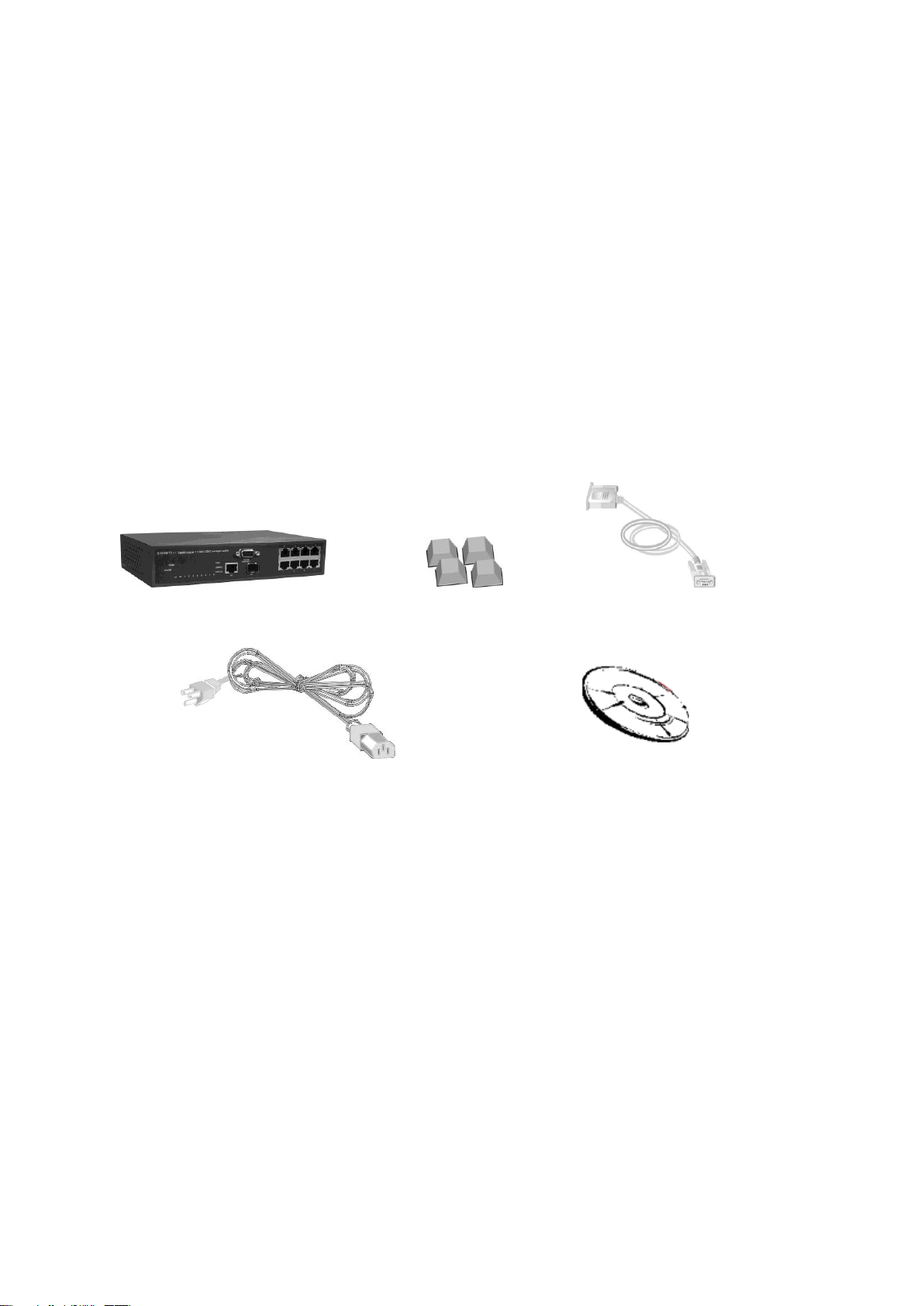
Package Contents
Unpack the contents of the 8 10/100TX plus 1 10/100/1000T + 1 MINI GBIC Managed
Switch and verify them against the checklist below:
8 10/100TX plus 1 10/100/1000T + 1 MINI GBIC Managed Switch
Four Rubber Pads
RS-232 cable
Power Cord
User Manual
8 10/100TX + 1 10/100/1000T Four Rubber Pads RS-232 cable
+ 1 Mini-GBIC Managed Switch
Power Cord User Manual
Compare the contents of your 8 10/100TX plus 1 10/100/1000T + 1 MINI GBIC Managed
Switch package with the standard checklist above. If any item is missing or damaged,
please contact the local dealer for exchanging.
6
Hardware Description
This section mainly describes the hardware of the 8 10/100TX plus 1 10/100/1000T + 1
MINI GBIC Managed Switch and gives a physical and functional overview on the certain
switch.
Physical Dimension
8 10/100TX plus 1 10/100/1000T + 1 MINI GBIC Managed Switch‘s physical dimensions
is 217mm(W) x 140mm(D) x 43mm(H).
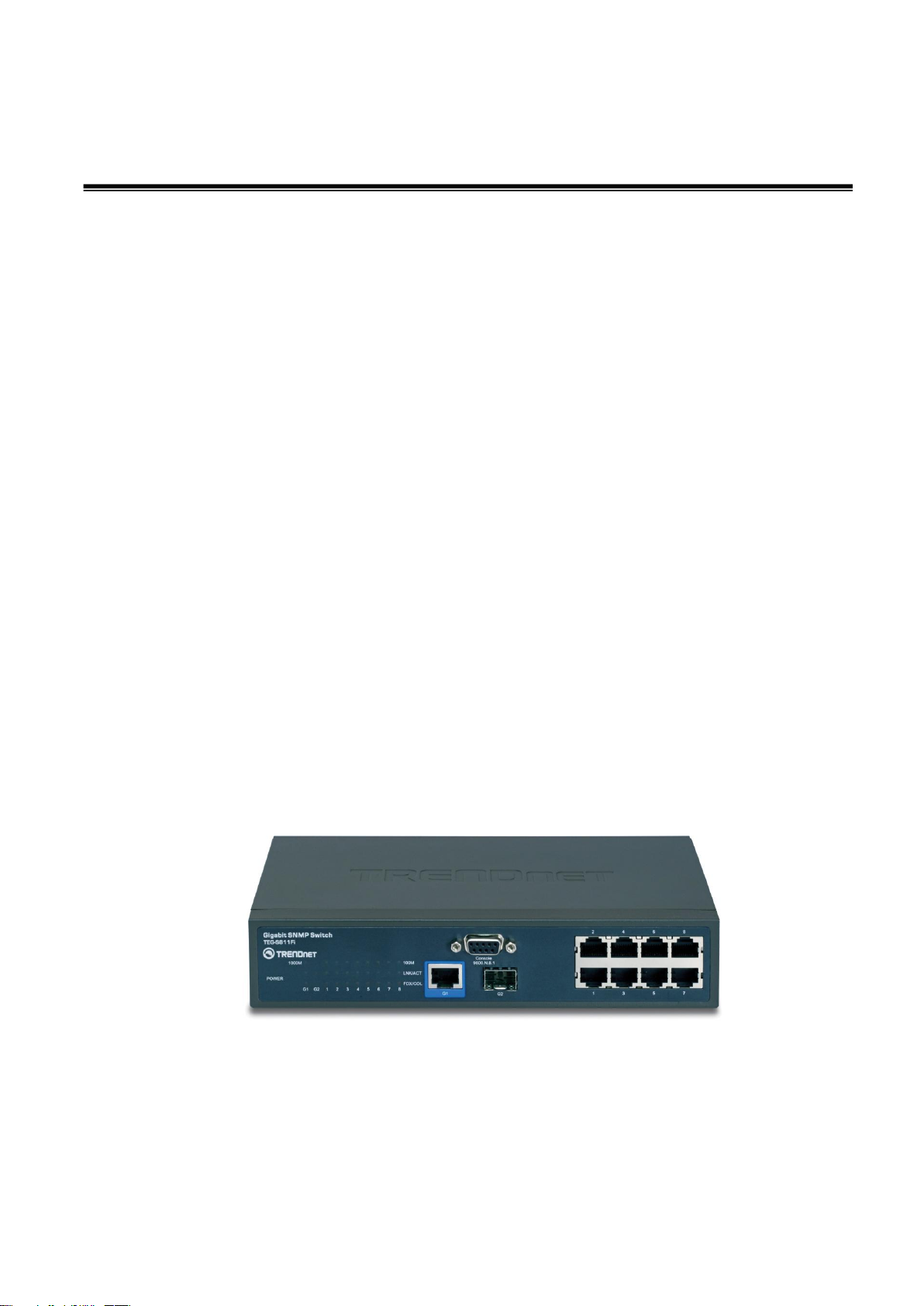
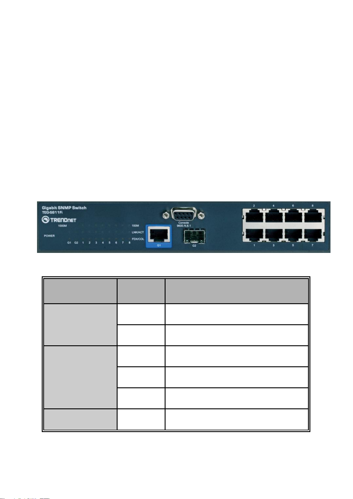
Front Panel
The front panel of the 8 10/100TX plus 1 10/100/1000T + 1 MINI GBIC Managed Switch
consists of 8x 10/100Base-TX RJ-45 ports (Auto MDI/MDIX), 1 Giga port and 1 Mini
GBIC module (module is optional). The LED Indicators are also located on the front
panel of the switch.
The Front panel of the 8 10/100TX plus 1 10/100/1000T + 1 MINI GBIC Managed Switch
RJ-45 Ports (Auto MDI/MDIX): 8x 10/100 N-way auto-sensing for 10Base-T or
100Base-TX connections.
In general, MDI means connecting to another Hub or Switch while MDIX means
7
connecting to a workstation or PC. Therefore, Auto MDI/MDIX would allow
LED
Status
Description
Power
Green
Power On
OFF
Power is not connected
100M
Green
In 100Mbps connection speed
Blink
In 10Mbps connection speed
OFF
No device attached
LNK/ACT
Green
The port is connecting with the device
connecting to another switch or workstation without changing non-crossover or
crossover cabling.
1 Giga port: 1x 10/100/1000TX N-Way auto-sensing for 10/100/1000 connection.
1 Mini GBIC port: one optional mini GBIC module port
LED Indicators
The LED Indicators display real-time information of systematic operation status. The
following table provides descriptions of LED status and their meaning.
LED indicators
8

Blink
The port is receiving or transmitting data
OFF
No device attached.
FDX/COL
Orange
The port is operating in Full-duplex mode
Blinks
Collision of packets occurs
OFF
In half-duplex mode
1000M (G1 port)
Green
In 1000Mbps connection speed
Orange
In 100Mbps connection speed
OFF
No device attached
LNK/ACT (G1 port)
Green
The port is connecting with the device
Blink
The port is receiving or transmitting data
OFF
No device attached
FDX/COL (G1 port)
Orange
The port is operating in Full-duplex mode
Blink
Collision of Packets occurs in the port
OFF
In half-duplex mode
LNK/ACT (G2 port)
Green
The port is connecting with the device
Blink
The port is receiving or transmitting data
Rear Panel
9

The 3-pronged power plug is located at the rear panel of the 8 10/100TX plus 1
10/100/1000T + 1 MINI GBIC Managed Switch as shown in figure. The switch will work
with AC in the voltage range of AC 100-240V and Frequency of 50-60Hz.
The Rear Panel of the 8 10/100TX plus 1 10/100/1000T + 1 MINI GBIC Managed Switch
Desktop Installation
Set the switch on a sufficiently large flat space with a power outlet nearby. The surface
where you put the switch should be clean, smooth, level and sturdy. Make sure there is
enough clearance around the switch to allow attachment of cables, power cord and allow
air circulation.
Attaching Rubber Pads
A. Make sure mounting surface on the bottom of the switch is grease and dust free.
B. Remove adhesive backing from your Rubber Pads.
C. Apply the Rubber Pads to each corner on the bottom of the switch. These footpads
can prevent the switch from shock/vibration.
Power On
Connect the power cord to the power socket on the rear panel of the switch. The other
side of power cord connects to the power outlet. The internal power supply of the switch
works with voltage range of AC in the 100-240VAC and Frequency of 50~60Hz. Check
the power indicator on the front panel to see if power is properly supplied.
10

Network Application
This section provides a few samples of network topology in which the switch is used. In
general, the 8 10/100TX plus 1 10/100/1000T + 1 MINI GBIC Managed Switch is
designed as a segment switch which with its large address table (8k MAC address) and
high performance, it is ideal for interconnecting networking segments.
PC, workstations, and servers can communicate each other by directly connecting with 8
10/100TX plus 1 10/100/1000T + 1 MINI GBIC Managed Switch. The switch
automatically learns nodes address, which are subsequently used to filter and forward all
traffic based on the destination address.
By using Uplink port, the switch can connect with another switch or hub to interconnect
other small-switched workgroups to form a larger switched network. Meanwhile, user can
also use fiber ports to connect switches.
Small Workgroup
The 8 10/100TX plus 1 10/100/1000T + 1 MINI GBIC Managed Switch can be used as a
standalone switch to which personal computers, server, printer server, are directly
connect to form a small workgroup.
11
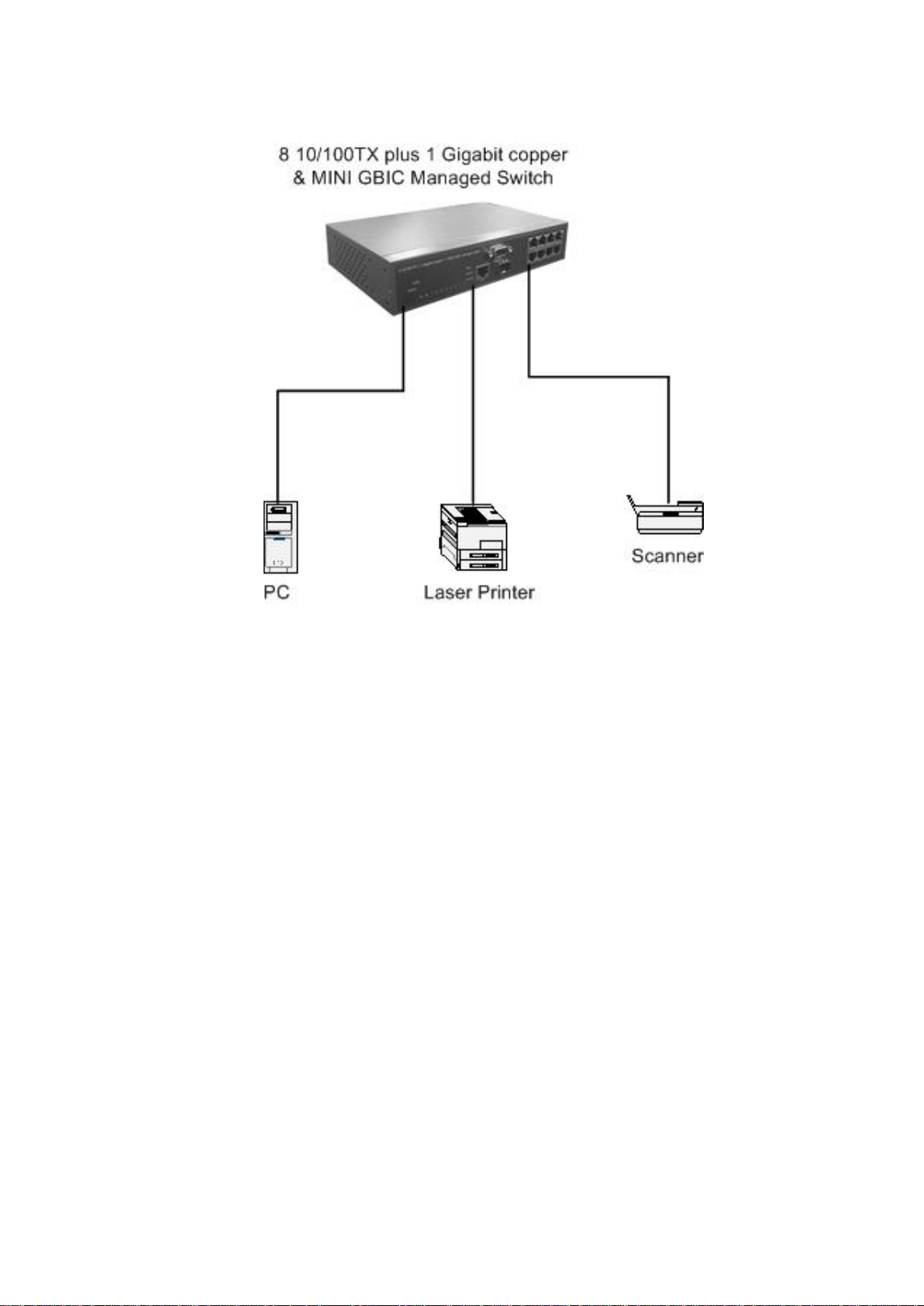
Small Workgroup application
Segment Bridge
For enterprise networks where large data broadcasts are constantly processed, this
switch is an ideal solution for department users to connect to the corporate backbone.
In the illustration below, two Ethernet switches with PCs, print server, and local server
attached, are both connect to the switch. All the devices in this network can
communicate with each other through the switch. Connecting servers to the switch allow
other users to access the data on server.
12
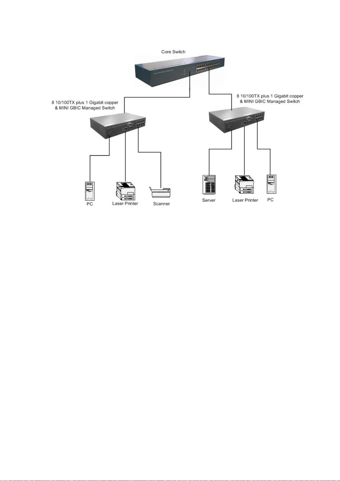
Segment Bridge application
13
Console Management
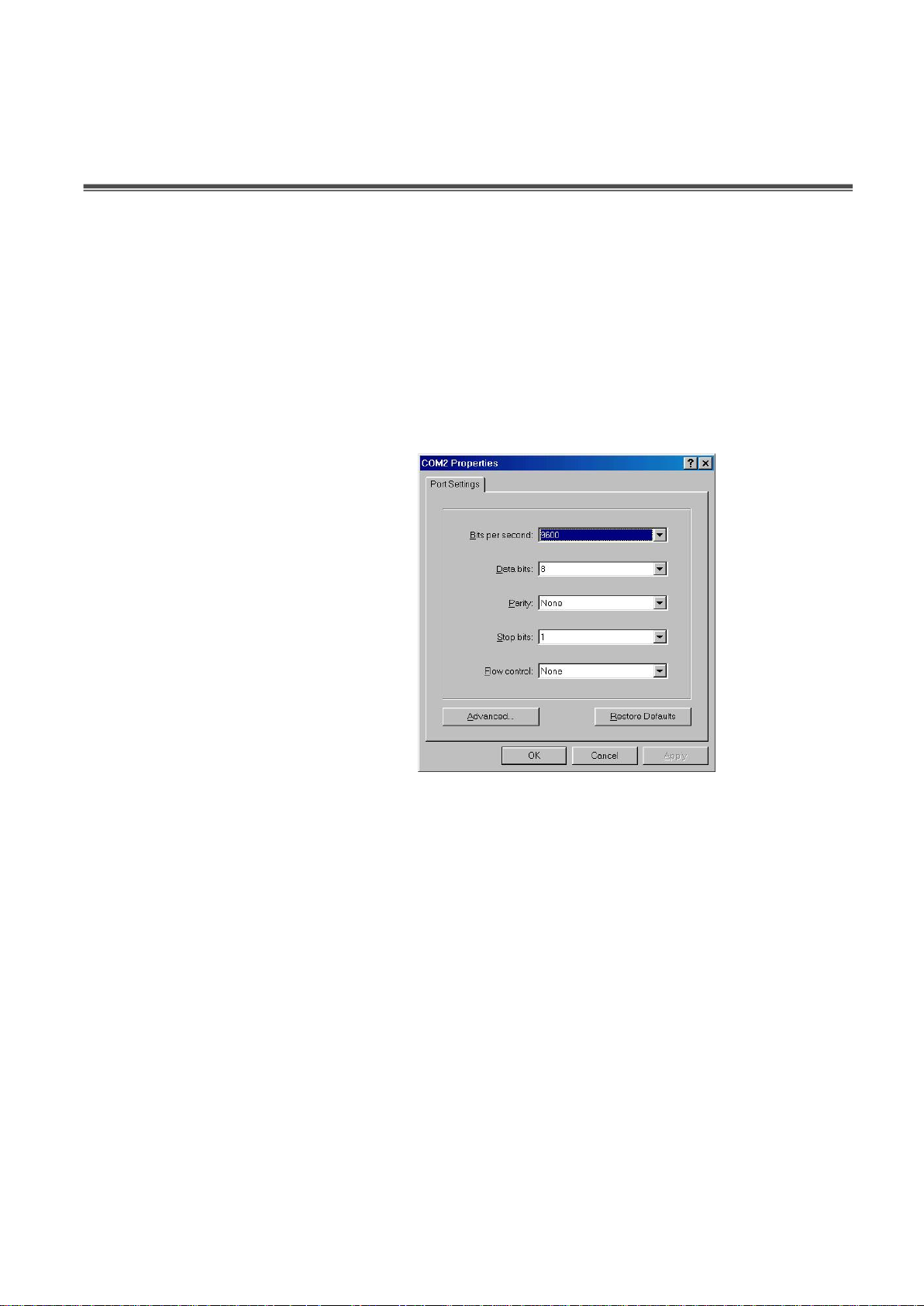
Login in the Console Interface
When the connection between switch and PC is ready, and then turn on the PC and run
a terminal emulation program or Hyper Terminal and configure its communication
parameters to match the following default characteristics of the console port:
Baud Rate: 9600 bps
Data Bits: 8
Parity: none
Stop Bit: 1
Flow control: None
The settings of communication parameters
After finished the parameter settings, click ―OK―. When the blank screen shows up, press
Enter key to bring out the login prompt. Key in the ―root―(default value) for the both User
name and Password (use Enter key to switch), then press Enter key and the console
management appears right after. Please see below figure for login screen.
14

Console login screen
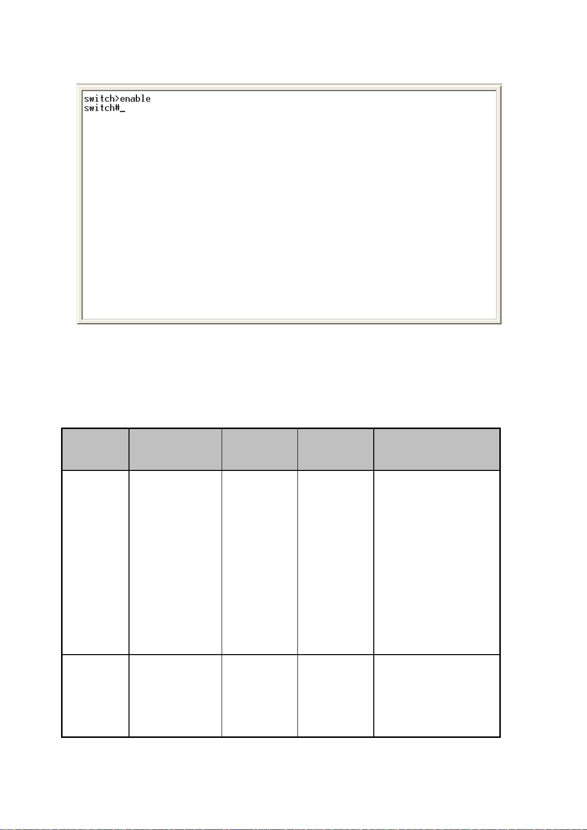
CLI Management
The system supports console management – CLI command. After you login to the
system, you will see a command prompt. To enter CLI management interface, enter
―enable‖ command. The following table lists the CLI commands and description.
15
Modes
Access
Method
Prompt
Exit
Method
About This Mode1
User
EXEC
Begin a
session with
your switch.
switch>
Enter
logout or
quit.
The user commands
available at the user
level are a subset of
those available at the
privileged level.
Use this mode to
• Perform basic tests.
• Display system
information.
Privileged
EXEC
Enter the
enable
command
while in user
switch#
Enter
disable to
exit.
The privileged
command is advance
mode
Privileged this mode
CLI command interface
Commands Level
16

EXEC mode.
to
• Display advance
function status
• Save configures
Global
Configura
tion
Enter the
configure
command
while in
privileged
EXEC mode.
switch
(config)#
To exit to
privileged
EXEC
mode,
enter exit or
end
Use this mode to
configure parameters
that apply to your
switch as a whole.
VLAN
database
Enter the vlan
database
command
while in
privileged
EXEC mode.
switch
(vlan)#
To exit to
user EXEC
mode,
enter exit.
Use this mode to
configure
VLAN-specific
parameters.
Interface
configurat
ion
Enter the
interface
command
(with a specific
interface)
while in global
configuration
mode
switch
(config-if)
#
To exit to
global
configuratio
n mode,
enter exit.
To exist to
privileged
EXEC
mode, or
end.
Use this mode to
configure parameters
for the switch and
Ethernet ports.
User EXEC E
Privileged EXEC P
Global configuration G
VLAN database V
Interface configuration I
17

Commands Set List
Netstar Commands
Level
Description
Example
show config
E
Show switch
configuration
switch>show config
show terminal
P
Show console
information
switch#show terminal
write memory
P
Save user
configuration into
permanent memory
(flash rom)
switch#write memory
system name
[System Name]
G
Configure system
name
switch(config)#system name xxx
system location
[System Location]
G
Set switch system
location string
switch(config)#system location
xxx
system description
[System Description]
G
Set switch system
description string
switch(config)#system
description xxx
system contact
[System Contact]
G
Set switch system
contact window string
switch(config)#system contact
xxx
show system-info
E
Show system
information
switch>show system-info
ip address
[Ip-address]
[Subnet-mask]
[Gateway]
G
Configure the IP
address of switch
switch(config)#ip address
192.168.1.1 255.255.255.0
192.168.1.254
ip dhcp
G
Enable DHCP client
function of switch
switch(config)#ip dhcp
show ip
P
Show IP information of
switch
switch#show ip
no ip dhcp
G
Disable DHCP client
function of switch
switch(config)#no ip dhcp
System Commands Set
18

reload
G
Halt and perform a cold
restart
switch(config)#reload
default
G
Restore to default
switch(config)#default
admin username
[Username]
G
Changes a login
username.
(maximum 10 words)
switch(config)#admin username
xxxxxx
admin password
[Password]
G
Specifies a password
(maximum 10 words)
switch(config)#admin password
xxxxxx
show admin
P
Show administrator
information
switch#show admin
dhcpserver enable
G
Enable DHCP Server
switch(config)#dhcpserver enable
Dhcpserver disable
G
Disable DHCP Server
switch(config)#no dhcpserver
dhcpserver lowip
[Low IP]
G
Configure low IP
address for IP pool
switch(config)#dhcpserver lowip
192.168.1.100
dhcpserver highip
[High IP]
G
Configure high IP
address for IP pool
switch(config)#dhcpserver highip
192.168.1.200
dhcpserver subnetmask
[Subnet mask]
G
Configure subnet
mask for DHCP clients
switch(config)#dhcpserver
subnetmask 255.255.255.0
dhcpserver gateway
[Gateway]
G
Configure gateway for
DHCP clients
switch(config)#dhcpserver
gateway 192.168.1.254
dhcpserver dnsip
[DNS IP]
G
Configure DNS IP for
DHCP clients
switch(config)#dhcpserver dnsip
192.168.1.1
dhcpserver leasetime
[Hours]
G
Configure lease time
(in hour)
switch(config)#dhcpserver
leasetime 1
dhcpserver ipbinding
[IP address]
I
Set static IP for DHCP
clients by port
switch(config)#interface
fastEthernet 2
switch(config)#dhcpserver
ipbinding 192.168.1.1
show dhcpserver
configuration
P
Show configuration of
DHCP server
switch#show dhcpserver
configuration
show dhcpserver clients
P
Show client entries of
DHCP server
switch#show dhcpserver clients
19

show dhcpserver
ip-binding
P
Show IP-Binding
information of DHCP
server
switch#show dhcpserver
ip-binding
no dhcpserver
G
Disable DHCP server
function
switch(config)#no dhcpserver
security enable
G
Enable IP security
function
switch(config)#security enable
security http
G
Enable IP security of
HTTP server
switch(config)#security http
security telnet
G
Enable IP security of
telnet server
switch(config)#security telnet
security ip
[Index(1..10)] [IP
Address]
G
Set the IP security list
switch(config)#security ip 1
192.168.1.55
show security
P
Show the information
of IP security
switch#show security
no security
G
Disable IP security
function
switch(config)#no security
no security http
G
Disable IP security of
HTTP server
switch(config)#no security http
no security telnet
G
Disable IP security of
telnet server
switch(config)#no security telnet
Netstar Commands
Level
Description
Example
interface fastEthernet
[Portid]
G
Choose the port for
modification.
switch(config)#interface
fastEthernet 2
duplex
[full | half]
I
Use the duplex
configuration
command to specify
the duplex mode of
switch(config)#interface
fastEthernet 2
switch(config-if)#duplex full
Port Commands Set
20

operation for Fast
Ethernet.
speed
[10|100|1000|auto]
I
Use the speed
configuration
command to specify
the speed mode of
operation for Fast
Ethernet., the speed
can‘t be set to 1000 if
the port isn‘t a giga
port..
switch(config)#interface
fastEthernet 2
switch(config-if)#speed 100
no flowcontrol
I
Disable flow control of
interface
switch(config-if)#no flowcontrol
security enable
I
Enable security of
interface
switch(config)#interface
fastEthernet 2
switch(config-if)#security enable
no security
I
Disable security of
interface
switch(config)#interface
fastEthernet 2
switch(config-if)#no security
bandwidth type all
I
Set interface ingress
limit frame type to
―accept all frame‖
switch(config)#interface
fastEthernet 2
switch(config-if)#bandwidth type
all
bandwidth type
broadcast-multicast-floo
ded-unicast
I
Set interface ingress
limit frame type to
―accept broadcast,
multicast, and flooded
unicast frame‖
switch(config)#interface
fastEthernet 2
switch(config-if)#bandwidth type
broadcast-multicast-flooded-uni
cast
bandwidth type
broadcast-multicast
I
Set interface ingress
limit frame type to
―accept broadcast and
switch(config)#interface
fastEthernet 2
switch(config-if)#bandwidth type
21

multicast frame‖
broadcast-multicast
bandwidth type
broadcast-only
I
Set interface ingress
limit frame type to
―only accept broadcast
frame‖
switch(config)#interface
fastEthernet 2
switch(config-if)#bandwidth type
broadcast-only
bandwidth in
[Value]
I
Set interface input
bandwidth. Rate
Range is from 100
kbps to 102400 kbps
or to 256000 kbps for
giga ports,
and zero means no
limit.
switch(config)#interface
fastEthernet 2
switch(config-if)#bandwidth in 100
bandwidth out
[Value]
Set interface output
bandwidth. Rate
Range is from 100
kbps to 102400 kbps
or to 256000 kbps for
giga ports,
and zero means no
limit.
switch(config)#interface
fastEthernet 2
switch(config-if)#bandwidth out
100
show bandwidth
I
Show interfaces
bandwidth control
switch(config)#interface
fastEthernet 2
switch(config-if)#show bandwidth
state
[Enable | Disable]
I
Use the state interface
configuration
command to specify
the state mode of
operation for Ethernet
ports. Use the disable
form of this command
switch(config)#interface
fastEthernet 2
22

to disable the port.
show interface
configuration
I
show interface
configuration status
switch(config)#interface
fastEthernet 2
switch(config-if)#show interface
configuration
show interface status
I
show interface actual
status
switch(config)#interface
fastEthernet 2
show interface
accounting
I
show interface statistic
counter
switch(config)#interface
fastEthernet 2
accounting
no accounting
I
Clear interface
accounting information
switch(config)#interface
fastEthernet 2
switch(config-if)#no accounting
Netstar Commands
Level
Description
Example
aggregator priority
[1~65535]
G
Set port group system
priority
switch(config)#aggregator priority
22
aggregator activityport
[Group ID]
[Port Numbers]
G
Set activity port
switch(config)#aggregator
activityport 2
aggregator group
[GroupID] [Port-list]
lacp
workp
[Workport]
G
Assign a trunk group
with LACP active.
[GroupID] :1~3
[Port-list]:Member port
list, This parameter
could be a port
range(ex.1-4) or a port
list separate by a
switch(config)#aggregator group
1 1-4 lacp workp 2
or
switch(config)#aggregator group
2 1,4,3 lacp workp 3
Trunk Commands Set
23
 Loading...