

Page 1

Preface
This manual describes how to install and use 16/24 port
Ethernet switch, TE100-S1616V/TE100-S2424V. It features
16/24 ports that auto negotiate the presence of 10/100Mbps
and full or half-duplex mode. An optional 100BASE-FX
multi-mode or single-mode module enables long-distance
connection. An optional BNC module enables backwards
compatibility.
To get the most out of this manual, you should have an
understanding of networking concepts such as bridging, IEEE
802.3 Ethernet and 100BASE-TX Fast Ethernet, and local area
networks (LAN).
For more information about these topics, please refer to the
Appendices.
In this manual, you will find:
Benefits of Ethernet switches
Features of TE100-S1616V/TE100-S2424V
LED functions illustration
Installation instr uctions
Configuration instructions for VLAN and port speed
Specifications
Ethernet technology, LAN, and VLAN tutorial information
Page 2

Table of Contents
Preface...........................................................................1
Introduction ..................................................................3
Benefits of Switching...........................................................................3
TE100-S1616V/TE100 -S2424V........................................................4
Product Features....................................................................................5
Packing List...........................................................................................7
Ports..................................................................................................10
LED Indicator .................................................................................13
Installation...................................................................18
Selecting a Site for the Switch..........................................................18
Connecting to Power..........................................................................20
Connecting to Your Network....................................20
Optional Module Installation............................................................23
Jumper Settings..............................................................................24
Switch Configuration.................................................26
Setting up Console Port Connection................................................27
VLAN ...................................................................................................31
Port Setting...........................................................................................35
Auto-Negotiation............................................................................35
Flow-Control...................................................................................35
Trunking...............................................................................................41
Networking Examples.....................................................................42
2 User’s Guide
Page 3

Specifications.............................................................46
Appendix A - Connector Pinouts.............................48
Appendix B - Introduction to LAN & Ethernet
Technologies..............................................................49
Appendix C – VLANs .................................................54
Introduction
Benefits of Switching
Ethernet switching technology has dramatically boosted the total
bandwidth of a network. It puts configuration flexibility and
bandwidth adaptability into the local workgroups where the
majority of work is generated.
It further eliminates congestion problems inherent to the
CSMA/CD protocol and improves predictable response time under
heavy network loads. Expensive routing equipment was used in the
past to reduce the congestion under heavy loads.
The new wave of object-oriented client and server applications
demands higher bandwidth and tighter integration of client
workstations with servers. The old shared-access (hub/repeater)
User’s Guide 3
Page 4

Ethernet technology provides neither enough bandwidth nor
predictable response time for this new wave of workgroup
computing.
Fast Ethernet switching not only satisfies both technical and
business requirements, but also preserves the user’ s existing
investment in the huge 10 Base -T Ethernet installed Base.
This compatibility ensures a path for users to add, change, and
migrate to Fast Ethernet as demands emerge. It also provides a low
cost and flexible bandwidth solution directly to local workgroups
where the majority of work is generated, reducing the need for
expensive network equipment.
TE100-S1616V/TE100-S2424V
16/24-port 10/100BASE-TX Fast Ethernet Switch
TE100-S1616V/TE100 -S2424V has 16/24 10/100Mbps ports with
an optional fiber-optic module, flexibly meeting fiber-optic needs.
The straight-forward design enables ease of operation while
providing superior performance.
Addressing the demand for fiber, we provide an optional multimode or single-mode fiber module for TE100-
4 User’s Guide
Page 5

S1616V/TE100S2424V as an optimum solution for long-distance
connectivity. The module supports one SC, ST, MT-RJ, or VF -45
port. A BNC connector is also available to address the backward
compatibility issue.
This switch represent the newest generation in Ethernet switching
technology by supporting both 10Mbps and 100Mbps speed and
half or full duplex transmission modes on the same port. By using
standard auto-negotiation, it provides a cost-effective way of
integrating legacy 10Mbps segments with 100Mbps Fast Ethernet
networks and an ideal solution for extending the distance between
two 100Mbps network segments.
TE100-S1616V/TE100 -S2424V supports port -based Virtual Local
Area Networking (VLAN). This advanced feature gives the
network administrator a powerful, yet easy-to-use tool to reduce
unnecessary broadcast traffic, flexibly segment the network, and
enhance network security.
TE100-S1616V/TE100S2424V fully complies with IEEE802.3u,
100BASE -TX/FX, and IEEE802.3, 10BASE-T standards
Product Features
- 16/24 ports with auto-negotiation 10/100Mbps
- Optional 1-port ST, SC, MT-RJ, VF-45, or BNC module.
User’s Guide 5
Page 6

- Plug-and-play
- Auto-negotiation for speed and duplex mode
- True non-blocking architecture
- Full wire speed forwarding
- Store-and-forward mechanism
- Back pressure and IEEE 802.3x compliant flow control
- Supports 2K MAC address
- Port based VLAN
- Programmable re-configuration for fixed speed and duplex modes
- One uplink port activated by the push of a button
- Front panel reset button
- Front panel status LEDs
- Standard 19" rack -mount size
6 User’s Guide
Page 7

Packing List
When you unpack this product, you should find the items listed
below. Please inspect the contents, and report any apparent damage
or missing items immediately to your authorized reseller.
?? TE100-S1616V or TE100-S2424V
?? User’s Guide
?? AC power cord
?? Rack Mount Ears with screws
?? Serial Cable
User’s Guide 7
Page 8
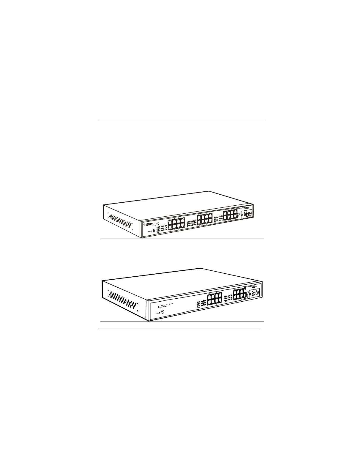
Front Panel
The front panel of this switch has 16 or 24 ports, one slot for an
optional fiber or BNC module and an array of LED indicators to
provide you with instant feedback on the status of the switch.
Figure 1: Front panel of TE100-S2424V
Figure 2: Front panel of TE100-S1616V
8 User’s Guide
Page 9

User’s Guide 9
Page 10

Ports
TE100-S1616V is similar to TE100-S2424V except that TE100S1616V has 16 RJ-45 10/100 Ethernet ports while TE100-S2424V
has 24. TE100-S1616V/TE100-S2424V also has one slot for
optional module for fiber or BNC connection.
The auto-negotiation feature of TE100-S1616V/TE100-S2424V
allows communication between 10Base-T(Ethernet) and 100BaseTX (Fast Ethernet) at full or half-duplex mode. If it is desirable to
operate at a fixed, rather than auto -negotiated media setting, please
refer to the Port Settings section on page 35.
The optional module of the switch provides an additional port for
copper BNC or fiber ST, SC, MT-RJ, or VF-45. The latter are
fiber-optic small -form-factor connectors that are smaller and easier
to use. The optional module port also allows the use of single-mode
fiber for distances up to 15 km. For information on module
installation, please refer to page 23.
The maximum range of a 100BASE-TX network connected to the
switch is 100 meters with Category 5 unshielded twisted-pair (UTP)
cable. A 10BASE-T network may range up to 100 meters with
Category 3, 4, or 5 UTP cable. As for the length of fiber link
between a switch and a Data Terminal Equipment, it is capable to
span at least 2 kilometers (1.24 Mile) using 62.5/125 -micron multi-
10 User’s Guide
Page 11

mode fiber-optic cable or up to 15 kilometers using 9 micron
single-mode fiber optic cable.
User’s Guide 11
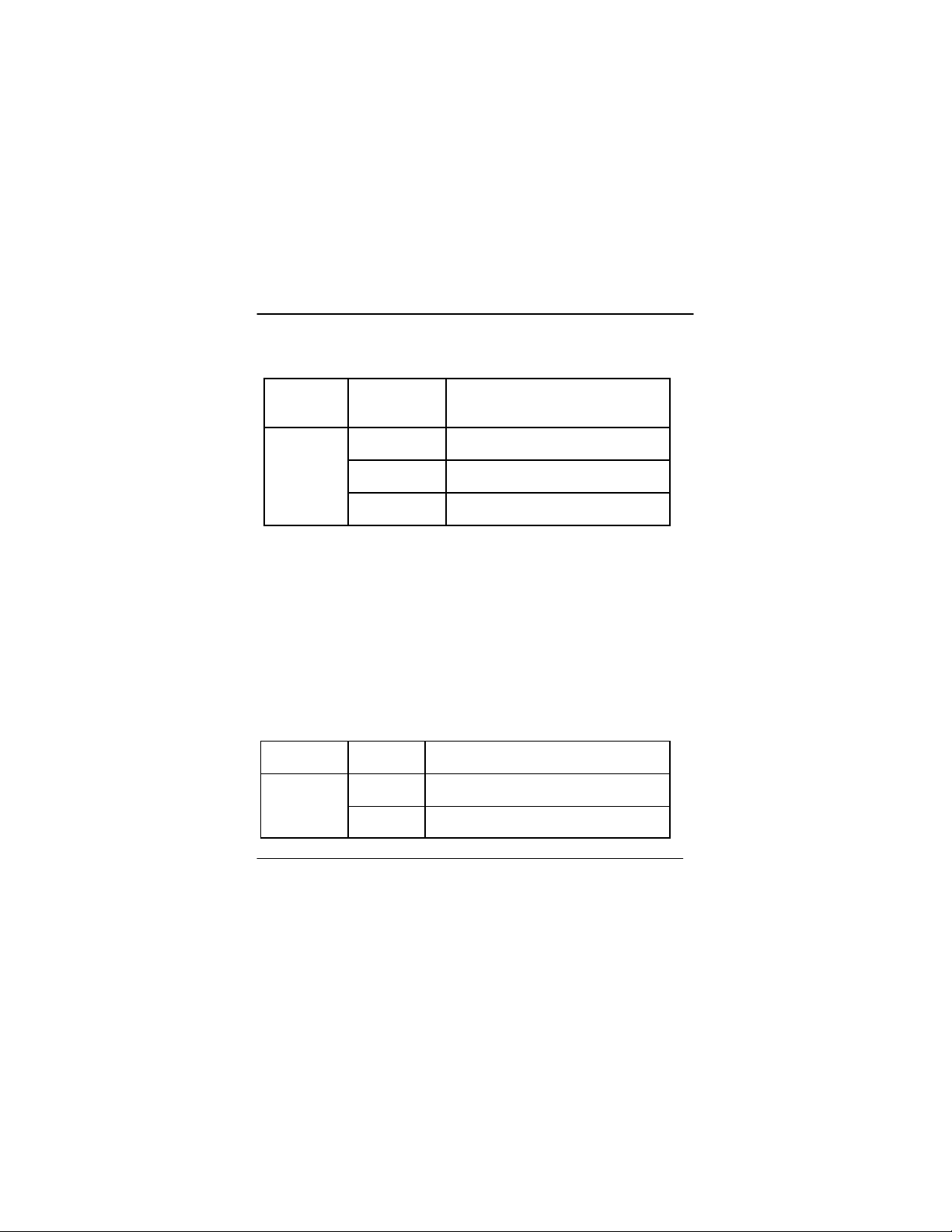
Page 12

Speed Connector Port Speed
Half/Full
Duplex
Cable Distance
10BASE-T RJ-45 10/20
100BASETX
100BASEFX
100BASEFX
10BASE-2 BNC 10Mbps Coaxial 500
RJ-45 100/200
ST, SC,
MT-RJ,
VF-45
ST, SC,
MT-RJ,
VF-45
Mbps
Mbps
100/200
Mbps
100/200
Mbps
Category 3,
4, or 5 UTP
Category 5
UTP
62.5/125
micron
multi-mode
fiber
9 micron
single-mode
fiber
100
meters
100
meters
2 km
15 km
meters
12 User’s Guide
Page 13
LED Indicator
The array of LED indicators on the front panel conveys status and
configuration information to help you monitor and trouble-shoot
the switch.
1X5X2X6X3X7X4X
RESET
POWER
24 port 10/100 switch
17X
9 10 11 12 13 14 15 16
LNK/ACT
100
FDX/COL
18X
19X
9X 10X 11X 12X
13X 14X 15X 16X
20X
8X
EXTENSION SLOT
21X
22X
23X
24X
User’s Guide 13
Page 14

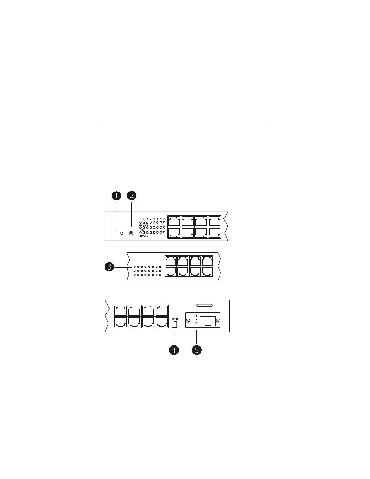
Figure 3: LED Indicator
14 User’s Guide
Page 15

?Power
This LED comes on when the switch is connected to a power
supply and turned on.
? Reset Button
If the switch should become unresponsive, you may perform a reset
of the switch by pressing this button.
? Port Status
The front panel of the switch has two segments of eight ports
numbered from 1X to 16X on TE100 -S1616V or three segments of
eight ports numbered from 1X to 24X on TE100-S2424V. The
LEDs are located at the left side of each segment, display status for
each respective port. Consult the following chart for clarification.
Table 1: Port Status
LED State Indication
Steady
LNK/ACT
Flashing
100 Steady
LINK: The port has established a
valid network connection
ACTIVITY: The port is
transmitting or receiving data
100Mbps: The port has
established a valid 100Mbps
network connection
User’s Guide 15
Page 16
Off
Steady
FDX/COL
Flashing
Off
? Uplink Button
Depress when connecting to another switch or hub’s MDI-X port
using a regular straight through twisted pair cable. Affects port
16X on TE100-S1616V or port 24X on TE100-S2424V only.
? Optional Module LEDs Status
A set of three LEDs displays the status of the optional modular port.
Consult the following char t for clarification.
Table 2: Optional module port status
LED State Indication
Steady
100/TX
Flashing The port is transmitting data
10Mbps:The port has established
a valid 10Mbps network
connection.
FULL-DUPLEX: The connection
is in full duplex mode
COLLISION: Collision occurred
in the 10/100 domain.
The connection is in half duplex
mode
100Mbps: The port has established
a valid network connection
16 User’s Guide
Page 17

10Mbps: The port has established a
valid net work connection
The port is receiving data
The connection is in full duplex
mode
10/RX
FDX/COL
Steady
Flashing
Steady
Flashing The port is receiving data
User’s Guide 17
Page 18

Installation
This chapter presents step-by-step installation instructions for
TE100-S1616V/TE100-S2424V.
Selecting a Site for the Switch
As with any electronic device, you should place the switch where it
will not be subjected to extreme temperatures, humidity, or
electromagnetic interference. The site you select should meet the
following requirements:
The room temperature should be between 32 and 104 degrees
Fahrenheit (0 to 40 degrees Celsius).
The relative humidity should be less than 90 percent,
non-condensing.
Surrounding electrical devices should not exceed the
electromagnetic field (RFC) standards for IEC 801-3, Level 2
(3V/M) field strength.
Make sure that the switch receives adequate ventilation. Do not
block the ventilation holes on the side of the switch or the fan
exhaust port on the rear of the switch.
The power outlet should be within 1.8Meter of the switch.
Detailed specifications may be found on page 46.
18 User’s Guide
Page 19

User’s Guide 19
Page 20

Connecting to Power
Connect the supplied AC power cord to the receptacle on the back
of the switch, and then plug the cord into a standard AC outlet with
a voltage range from 100 to 240 VAC.
Turn the switch on by flipping the ON/OFF switch on the rear of
the unit to the I (ON) position. The O position is OFF.
Connecting to Your Network
Prepare cable with corresponding connectors fo r each type of port
in use. Consult Table 3 below for cabling requirements based on
connectors and speed. Once the connections are made, the switch is
operational.
20 User’s Guide
Page 21

Table 3: Cable Specifications
Speed Connector Port
Speed
Half/Full
Duplex
Cable Distance
10BASE-T RJ-45 10/20
100BASETX
100BASEFX
100BASEFX
10BASE-2 BNC 10Mbps Coaxial 500
RJ-45 100/200
ST, SC,
MT-RJ,
VF-45
ST, SC,
MT-RJ,
VF-45
Mbps
Mbps
100/200
Mbps
100/200
Mbps
Category 3,
4, or 5 UTP
Category 5
UTP
62.5/125
micron
multi-mode
fiber
9 micron
single-mode
fiber
100
meters
100
meters
2 km
15 km
meters
When the uplink button is pressed down, port 16X on TE100S1616V or port 24X on TE100-S2424V can be used to connect to
any regular port of another hub or switch using a regular straight
through twisted pair cable. To connect two regular RJ -45 ports
between any switches or hubs, you need a cross-wire cable. The
User’s Guide 21
Page 22

cable must be a Category 5 shielded twisted-pair or unshielded
twisted-pair (STP/UTP) cable for 100BASE-TX, or Category 3, 4,
or 5 STP/UTP cable for 10BASE -T.
22 User’s Guide
Page 23

Optional Module Installation
The switch offers an optional one-port module for fiber or BNC
connection. The fiber module is available in either single or multimode, it supports SC, ST, MT-RJ or VF-45 connector.
The optional module should be inserted into the extension slot
located at the right side of the switch. Port 16X (for TE100S1616V) or port 20X (for TE100-S2424V) will be automatically
disabled when optional module is installed. Before installation,
ensure that the power is disconnected. The module is not hotswappable. Unscrew the cover plate in the extension slot. Pull out
the cover plate and slide the module in the metal guides slowly.
Once the module is fully seated in the slot, tighten the screws.
User’s Guide 23
Page 24

Figure 4: Removal of cover plate
Figure 5: Module being installed
Jumper Settings
The module arrives with pre-set jumpers and should not be reset.
24 User’s Guide
Page 25

Figure 6: Proper jumper settings for fiber module (BNC connection
does not have a jumper)
User’s Guide 25
Page 26

Switch Configuration
Configurable features such as VLAN, port setting, flow-control,
and trunking are gradually becoming necessary functions of a
switch for setting up networks.
TE100-S1616V/TE100 -S2424V incorporates those features into a
configuration manual, where you can easily assign individual port
to one or several VLAN groups, set fixed speed or duplex mode,
link together several ports to act as a single port with higher
bandwidth (Trunking), and enable or disable flow-control. This
section explains, in detail, how to configure these features through
serial port connection. A serial cable is provided with the switch.
Use it to connect the console port at the back of the switch and a
COM port on the computer. Information on next page explains
steps for setting up the console port connection.
26 User’s Guide
Page 27

Setting up Console Port Connection
Check the switch, cables, and computer; make sure they are
functioning properly before the configuration.
Attach a PC or any VT100 compatible terminal to the console port
on the back of the switch (see figure 7) using the following settings:
Terminal type VT100
Port type (COM 1~4)
Communication
Mode
Flow Control None
Hardware
Compression
User’s Guide 27
8 data bits, 1 stop bit, no
parity and 9600bps
(for initial configuration)
NA
Page 28

Console Port
Figure 7: Console Port
After DOS or Hyper Terminal programs have been set up properly,
turn on the switch, use terminal program to connect to the switch
and press any key to view the main menu shown below:
24-port 10/100 Base Ethernet Switch
VLAN Port List
V1, 1,2,3,4,5,6,7,8,9,10,11,12,13,14,15,16,17,18,19,20,21,22,23,24
V2 < empty >
V3 < empty>
V4 < empty >
Port Mode FLW VLAN Port Mode FLW VLAN
1 Auto Y V1 13 Auto Y V1
28 User’s Guide
Page 29

2 Auto Y V1 14 Auto Y V1
3 Auto Y V1 15 Auto Y V1
4 Auto Y V1 16 Auto Y V1
5 Auto Y V1 17 Auto Y V1
6 Auto Y V1 18 Auto Y V1
7 Auto Y V1 19 Auto Y V1
8 Auto Y V1 20 Auto Y V1
9 Auto Y V1 21 Auto Y V1
10 Auto Y V1 22 Auto Y V1
11 Auto Y V1 23 Auto Y V1
12 Auto Y V1 24 Auto Y V1
VLAN/Mode/Trunking/Default (V/M/T/D) ?
Note: The terminal mode setup command and options are the
same for TE100-S1616V and TE100-S2424V. Only the
number of ports shown on the screen is different.
Mode = Speed and Duplex mode
FLW = Flow Control
This main menu shows you the default configuration of the switch.
By default, all ports are set at auto-negotiation, flow control on, and
all ports are grouped into V1 (VLAN group 1).
These are the valid commands:
[V] Configure VLAN groups
[M] Select 10/100Mbps and half or full-duplex mode
User’s Guide 29
Page 30

[T] Select Trunking
[D] Restore the default settings
[ESC] Abort the menu at any time
Note: [Esc] will not function when you are in the Trunking Menu.
In the Trunking setup menu, you must select trunk “a” or “b”. To
cancel the trunking selection, select “D” at main menu to restore to
default settings. When “D” is selected and confirmed, all settings
will go back to default.
30 User’s Guide
Page 31

VLAN
Virtual Local Area Networking (VLAN) enables efficient traffic
separation, provides better bandwidth utilization, and alleviates
scaling issues by logically segmenting the physical LAN so that
packets are switched only between ports within the same VLAN.
This also creates secure segments within the existing network.
Nodes residing in different VLAN segments cannot communicate
with each other although they are connected to the same switch.
The resulting security is yet another reason to use VLAN.
This switch is able to support up to four port -based Virtual LAN
(VLAN) domains. Follow these steps to assign ports to a VLAN
group.
?? Enter [V] from the Main Menu
?? Select a VLAN group:
[V1], [V2], [V3], or [V4]
?? Enter the port number.
Note: If entering more than one port to a VLAN group,
separate each port number by commas. For setting
consecutive number of ports to the same VLAN, use –
between the first and last port numbers to save time.
User’s Guide 31
Page 32

Only one VLAN group can be defined at a time. Repeat the steps
until all ports are assigned to at least one VLAN group. Though
each VLAN grouping does not need to be utilized, each port must
be assigned to at least one VLAN group. Hit the [ESC] key when
done.
To return to the default settings (in which each port is assigned to
V1), enter [D] from the main menu and enter Y to confirm the
action.
VLAN Example:
VLAN/Media/Default (V/M/D)? V
Please enter the VLAN# or ESC to abort (V1-V4) -> V1
The current V1 is 1,2,3,4,5,6,7,8,9,10,11,12,13,14,15,16,17,18,19,20,21,22,23,24
Please enter the new port list ->
Key 1-3,8,10,14,15, 17-20,22,24
Proceed with the assignment of the remainder of the ports into any
VLAN grouping:
Enter [V2]
32 User’s Guide
Page 33

Key 1,4,5,6,8,12,13,19,21,23
Enter [V3]
Key 1,7,9,11,16,19,21,23
Note: Until assigned, the menu displays **error** for each
unassigned port. While any port is in the **error ** status, the [ESC]
key will not return the screen to the main menu. Assign each port to
a VLAN grouping prior to exiting program.
User’s Guide 33
Page 34

View the results on the following illustration.
24-port 10/100 Base Ethernet Switch
VLAN Port List
V1, 1,2,3,8,10,14,15,17,18,19,20,22,24
V2, 1,4,5,6,8,12,13,19,21,23
V3, 1,7,9,11,16,19,21,23
V4 < empty >
Port Mode FLW VLAN Port Mode FLW VLAN
1 Auto Y V1 V2 V3 13 Auto Y V2
2 Auto Y V1 14 Auto Y V1
3 Auto Y V1 15 Auto Y V1
4 Auto Y V2 16 Auto Y V3
5 Auto Y V2 17 Auto Y V1
6 Auto Y V2 18 Auto Y V1
7 Auto Y V3 19 Auto Y V1 V2 V3
8 Auto Y V1 V2 20 Auto Y V1
9 Auto Y V3 21 Auto Y V2 V3
10 Auto Y V1 22 Auto Y V1
11 Auto Y V3 23 Auto Y V2 V3
12 Auto Y V2 24 Auto Y V1
VLAN/Mode/Trunking/Default (V/M/T/D) ?
34 User’s Guide
Page 35

Port Setting
When connecting the Switch to legacy networking equipments, it
may be necessary to disable auto-negotiation and flow control. This
can be done by selecting “M” at the terminal mode main menu and
then select the desire port speed, duplex mode, and flow control on
/off.
Auto-Negotiation
Every TX ports on the switch is capable of auto-negotiate
10/100Mbps and full or half– duplex. However, at times it might
need to disable this function in order to accommodate operations
involving legacy equipment. The duplex and speed can be altered
by enter [M] on the configuration manual. Please see next page for
detailed information.
Flow-Control
This flow control mechanism is set up between the two stations on
the point-to-point link. If the receiving station at the end becomes
congested, it can send back a frame called a "pause frame" to the
source at the opposite end of the connection that instructs that
User’s Guide 35
Page 36

station to stop sending packets for a specific period of time. The
sending station will wait the requested time before sending more
data. The receiving station can also send a frame back to the source
with a time-to-wait of zero and instruct the source to begin sending
data again.
The flow-control mechanism of this switch can be turned off to
accommodate special needs at different network environments.
Information below illustrate steps of changing the speed/duplex
mode setting or to toggle flow control ON/OFF:
Enter [M] (don’t need to hit [ENTER] after this)
Select a port
Select the media (0~5) from the list that appears on the screen
Note: Only one port can be configured at a time.
Consult the following chart for a brief description:
Communication
#
Media
Description
0 Flow control Toggles off/on
1 Auto Auto-Negotiation
2 100FD 100Mbps at full duplex mode
36 User’s Guide
Page 37

3 100HD 100Mbps at half duplex mode
4 10FD 10Mbps at full duplex mode
5 10HD 10Mbps at half duplex mode
User’s Guide 37
Page 38

Example:
Enter [M ]
Select port 6
Select communication media 5
View the results on the following illustration.
24-port 10/100 Base Ethernet Switch
VLAN Port List
V1, 1,2,3,4,5,6,7,8,9,10,11,12,13,14,15,16,17,18,19,20,21,22,23,24
V2 < empty >
V3 < empty>
V4 < empty >
Port Mode FLW VLAN Port Mode FLW VLAN
1 Auto Y V1 V2 V3 13 Auto Y V2
2 Auto Y V1 14 Auto Y V1
3 Auto Y V1 15 Auto Y V1
4 Auto Y V2 16 Auto Y V3
5 Auto Y V2 17 Auto Y V1
6 10HD Y V2 18 Auto Y V1
7 Auto Y V3 19 Auto Y V1 V2 V3
8 Auto Y V1 V2 20 Auto Y V1
9 Auto Y V3 21 Auto Y V2 V3
38 User’s Guide
Page 39

10 Auto Y V1 22 Auto Y V1
11 Auto Y V3 23 Auto Y V2 V3
12 Auto Y V2 24 Auto Y V1
VLAN/Mode/Trunking/Default
(V/M/D) ?
User’s Guide 39
Page 40

When the optional module is installed, port 16 (for TE100-S1616V)
or port 20 (for TE100-S2424V) will be automatically disabled.
However, on the switch configuration program, port #16 or #20
will show status of the optional module . The port setting for the
optional module is slightly different from the regular port.
Consult the following chart for a brief description:
Communication
#
Media
0 Flow control Toggles off/on
1 FX FD 100Mbps at full duplex mode
2 FX HD 100Mbps at half duplex mode
Description
40 User’s Guide
Page 41

Trunking
Trunking is a method of physically links several ports together to
act as a single port with higher bandwidth. This switch offers you
the choices of 2 ports or 4 ports trunking. Follow these steps to
configure trunking.
?? Enter [T]
Select [A] for 2-port trunking or select [B] for 4-port trunking
View the results on the following illustration.
24-port 10/100 Base Ethernet Switch
VLAN/Media/Default/Trunk (V/M/D/T) ? T
Select Trunk Port
A. 1, 2
B. 1, 2, 3, 4
? A
Port Mode FLW Port Mode FLW
1 Auto Y Trunk 13 Auto Y
2 Auto Y Trunk 14 Auto Y
3 Auto Y 15 Auto Y
4 Auto Y 16 Auto Y
5 Auto Y 17 Auto Y
6 10HD Y 18 Auto Y
7 Auto Y 19 Auto Y
User’s Guide 41
Page 42

200Mbps
Fast Ethernet
8 Auto Y 20 Auto Y
9 Auto Y 21 Auto Y
10 Auto Y 22 Auto Y
11 Auto Y 23 Auto Y
12 Auto Y 24 Auto Y
Networking Examples
10Mbps
Half-duplex
Ethernet
Workstation
Printer server
Full-duplex
Fast Ethernet
Workstation
Full-duplex
Server
Figure 8: High-speed connections for a small workgroup
42 User’s Guide
Page 43

Server 1
Server 2
10Base-T Hub
10Mbps
200Mbps
200Mbps
100Mbps
100Base-TX Hub
100Mbps
10Mbps
10Base-T Hub
Figure 9: Collapsed backbone for workgroups
User’s Guide 43
Page 44

44 User’s Guide
Page 45

100Mbps
100Mbps
100Base-TX Hub
100Base-TX Hub
10Base-T Hub
10Mbps
10Mbps
10Base-T Hub
Figure 10: Bridging existing hub-based 100BASE -TX and
10BASE -T network
User’s Guide 45
Page 46

Specifications
TE100-S1616V/TE100-S2424V
Applicable
Standards
Ports 16/24 10/100-BASE-T/TX
Speed
Performance 148,800bps forwarding rate per port for 100Mbps.
LED
Indicators
10BASE-T, IEEE 802.3 100BASE-TX &
100BASE-FX, IEEE 802.3u
100BASE-FX:
200Mbps full-duplex
100Mbps half-duplex
100BASE-TX:
200Mbps full-duplex
100Mbps half-duplex
10BASE-TX: 20Mbps full-duplex
10Mbps half-duplex
Power, Link, Activity, 100Mbps, Full-duplex,
Collision
Module
LED
Indicators
100/TX, 10/RX, FDX/COL
46 User’s Guide
Page 47

Dimensions 440 X 205 X 45 mm Rackmount Size
17.3 X 8.1 X 1.8 inch Rackmount Size
Weight 2.8kg
6.2lb
Power Input 100 ~ 250 Vac, 47/63 Hz, 2 A
Power
Consumption
Operating
Temperature
Humidity 10 ~ 90%, non-condensing
Altitude 3048 m
Emissions FCC part 15 Class A, CISPR Class A,
Safety UL, CSA, TUV/GS
20 W
0° ~ 40°C
32° ~ 104°F
10,000 ft
VCCI-I CE Mark
User’s Guide 47
Page 48

Appendix A - Connector Pinouts
Pin arrangement of RJ-45 connectors
Figure 11: RJ-45 Connector and Cable Pins
The following table lists the pinout of 10/100BASE -T/TX ports
Table 4: Connector Pin-Out
Pin Regular Ports Uplink port
1 Input Receive Data + Output Transmit Data +
2 Input Receive Data - Output Transmit Data 3 Output Transmit Data + Input Receive Data +
4 NC NC
5 NC NC
6 Output Transmit Data - Input Receive Data 7 NC NC
8 NC NC
48 User’s Guide
Page 49

Appendix B - Introduction to LAN &
Ethernet Technologies
As communication and business applications become increasingly
complex, computer networking has evolved as a very important
part of the infrastructure.
Communication systems like Local Area Network (LAN) evolved
into sophisticated, powerful, yet flexible technology. Among the
different types of LAN technologies, Ethernet represents the best in
speed, cost, ease of installation, and supportability.
LAN
Local Area Network (LAN) technology gave personal computers
the power to share resources of hardware and software. LAN
connects personal computers, file servers, printers, etc. together
within a geographical area, usually a single building. Multiple,
widely dispersed LAN systems are referred to as a wide area
network (WAN ).
Ethernet Technologies
User’s Guide 49
Page 50

More than 80 percent of all LANs utilize Ethernet technology. The
Institute of Electrical and Electronic Engineers (IEEE) standardized
Ethernet in IEEE 802.3, which provides for configuration rules,
interaction requirements, types of media, and data rate.
50 User’s Guide
Page 51

Fast Ethernet
For networks that need higher transmission speeds, a faster speed
was developed and IEEE next established IEEE 802.3u, raising the
Ethernet speed from 10 Mbps to 100 Mbps. Thus, fast Ethernet
arose and users quickly began converting from 10Mbps to
100Mbps.
Gigabit Ethernet
The demand for even higher speed created the gigabit Ethernet at
1000Mbps (or 1Gbps). The newer IEEE standard for gigabit
Ethernet is IEEE 802.3z. The only cabling media approved is the
fiber-optic pair. Watch for 10gig Ethernet.
User’s Guide 51
Page 52

Ethernet Products
Hub
One of the earlier connection solutions for Ethernet, a hub (also
called a repeater) operates by broadcasting data to all ports
simultaneously, only to repeat it when it is not received. The hub
works through a “shared network” with all of the nodes in the
network segment sharing the same collision domain. Switches and
bridges emerged because of a need to separate collision domains
that are too large, therefore improving performance and network
reliability.
Switch
A switch solves the collision problem by working as a single
domain. A Switch maps the physical Ethernet addresses of the
nodes residing on each network segment and then allows only the
necessary traffic to pass through. Packets of data are transmitted
along with the destination and source segment.
There are two basic architectures of LAN switches, cut-through and
store -and-forward. Cut-through switches consider only the
destination address before forwarding it on to its destination
segment, but store-and-forward architecture accepts and then
analyzes the entire packet before forwarding. This allows the
switch to stop certain packet errors from propagating through the
52 User’s Guide
Page 53

network. The store-and forward switch eliminates redundant or
corrupted packets, thus increasing the efficiency of the network
transmission.
User’s Guide 53
Page 54

LAN 1
LAN 2
LAN 2
Appendix C – VLANs
Virtual local area network (VLAN) is a network configuration in
which nodes are grouped into logical, rather than physical networks.
Figure 12 & 13 below shows the difference between LAN and
VLAN. The segmentation in VLAN creates secured areas where
sensitive information is not shared and creates its own broadcast
domain within the group to effectively reduce broadcast traffic,
providing higher network efficiency and security.
Figure 12: LAN Segmentation
54 User’s Guide
Page 55

VLAN 1
VLAN 2
Figure 13: VLAN Segmentation
User’s Guide 55
 Loading...