

Page 1
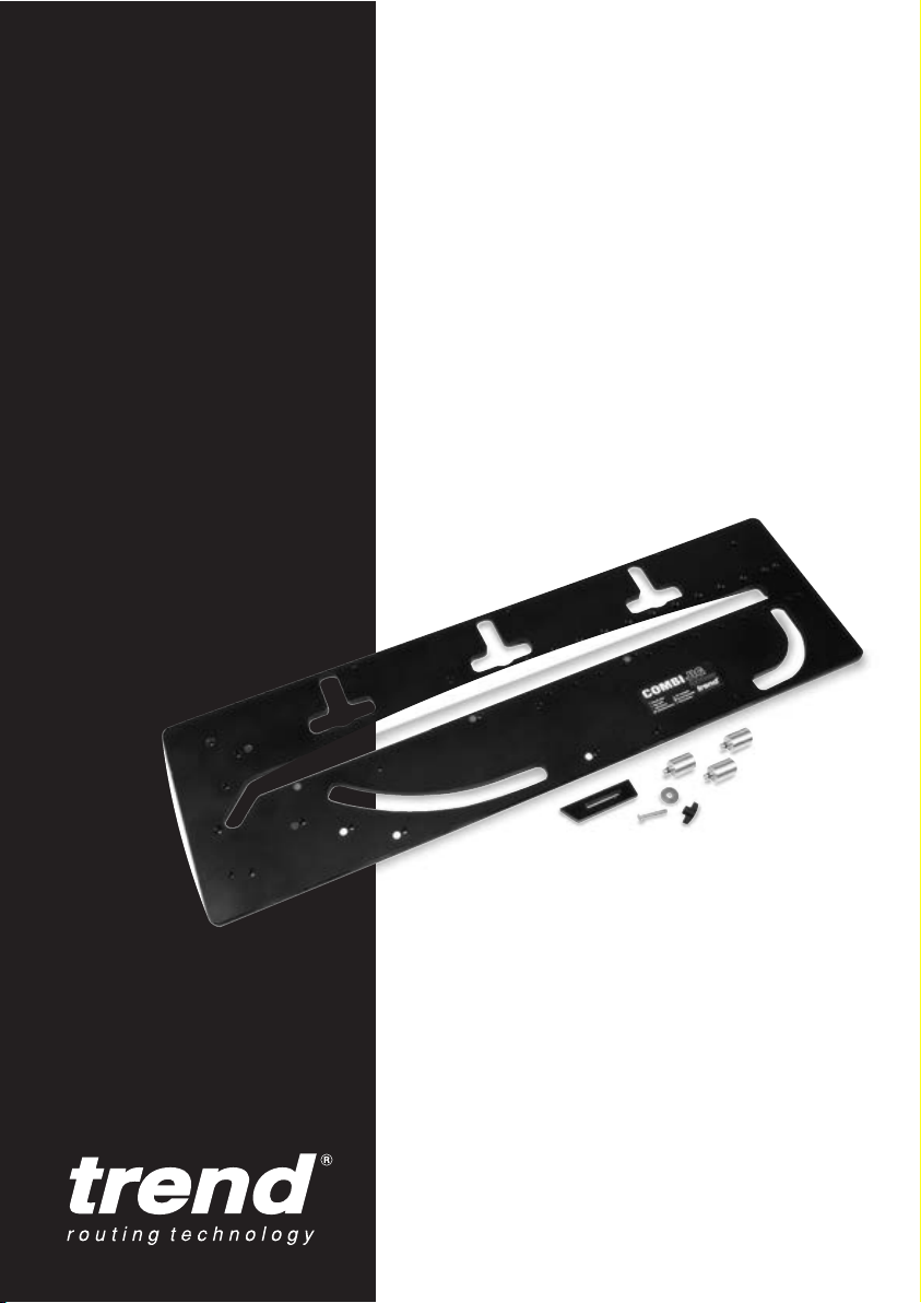
COMBI 1001
Page 2

Dear Customer
Thank you for purchasing this Trend product.
The Combi 1001 is designed to be used with
most heavy duty routers. The router should be
fitted with a 30mm outside diameter guide bush
and a 12.7mm (
1
/2”) diameter Tungsten Carbide
Tipped (TCT) cutter which should have plunge
cut facility.
Once the jig has been mastered a typical
postform or butt and scribe joint can be made in
15 minutes including setting-up time.
Recommended maximum depth of cut is 8mm in
one pass.
The jig is designed to cut worktop widths from
450mm to 1000mm. It will also cut a curved
peninsular, a 45° end cut, a corner radius and a
22.5° mitre joint.
If after reading these instructions you have any
problems please contact our Technical Support
Department. For accessories and a copy of the
latest Trend Routing Catalogue please contact
your nearest Trend stockist.
We hope you enjoy many years of productive
use of this product.
Please remember to return your
guarantee card within 14 days of
purchase.
Combi 1001
-1-
The following symbol is used throughout this
manual:
IMPORTANT!
Please take note of comments.
CONTENTS
ITEMS ENCLOSED ____________________2
SAFETY PRECAUTIONS________________3
– Cutter Care__________________________3
– Useful Advice ________________________3
ACCESSORIES _______________________4
– Recommended Cutters ________________4
– Sub-base Sets _____________________4-5
– Panel Butt Connectors _________________6
– Biscuit Jointer for the Router ____________6
– Gripper Clamp _______________________6
– Bolt-on Clamps_______________________7
– Carry Case __________________________7
ASSEMBLY___________________________8
– Location Bush Identification _____________8
– Margin Distance ______________________8
– Setting out the Joints __________________8
OPERATION __________________________9
– Setting the Length Stop ________________9
– Female Joint________________________10
– Male Joint __________________________11
– Out-of-square Joints_______________11–12
– Cutting the Bolt Recesses __________13–14
– Strengthening the Joint _______________15
– Sealing the Joint ____________________15
– Corner Radius ______________________16
– 22.5° Mitre Joint _____________________16
– Curved Peninsular ___________________17
– 45° End Cut ________________________18
SPARE PARTS
– Spare Parts List & Diagram _________19–20
TROUBLE SHOOTING ________________I/B
Please read the operating
instructions carefully and keep
them together with your jig.
If you require further technical information or spare parts for the
Combi, please call our technical support department on 01923 224681.
Page 3
-2-
Combi 1001
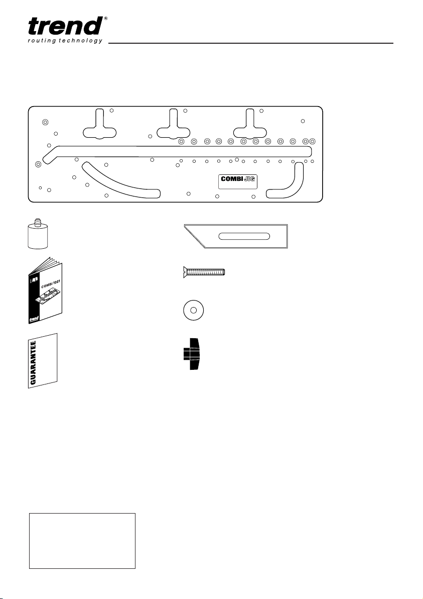
ITEMS ENCLOSED
Length = 1200mm
Width = 370mm
Thickness = 16mm
Weight = 9.6kg
Specification
1 x Solid laminate
combination template
2 x Location bushes
1 x Manual
1 x Guarantee card
1 x Length setting stop
1 x Machine screw csk
1 x Washer
1 x Knob
Page 4

Combi 1001
-3-
SAFETY PRECAUTIONS
I Always switch off the power and unplug the
router when changing cutters or when making
adjustments.
I Always wear protective goggles when routing.
I Wear sound protective ear muffs when routing
for long periods of time.
I Always wear a dust mask or respirator. Use
dust extraction equipment whenever possible.
I Do not wear loose clothing. Make sure baggy
sleeves are rolled up and ties are removed.
I Always remove spanners and hex keys from
the workpiece before switching router on.
I Keep hands well clear of the router cutter
when routing.
I Avoid accidental starting of the router. Make
sure the power switch is in the ‘Off’ position
before plugging in and connecting to the
electrical supply.
I Never leave the router unattended when
running. Always wait until the router comes to
a complete stop before making any
adjustments.
I Do not switch the router on with the cutter
touching the workpiece.
I Mount the workpiece securely to a work
bench or to a workboard fitted to a suitable
surface.
I Periodically check all nuts and bolts to make
sure they are tight and secure.
Cutter Care
I Do not drop cutters or knock them against
hard objects.
I Cutters should be kept clean. Resin build-up
should be removed at regular intervals with
Resin Cleaner
®
. The use of a dry lubricant
will act as a preventative such as Trendicote
®
PTFE spray.
I Cutter shanks should be inserted into the
collet at least
3
/4 of shank length to prevent
distortion. A distorted collet should be
discarded, as it can cause vibration and
damage the shank.
I Do not over-tighten collet as this will score the
shank and create a weakness there.
I It is also advisable to periodically check the
router collet nut for wear.
Useful Advice
I Judge your feed rate by the sound of the
motor. In time, the operator will acquire a
‘feel’ for the router, and a feed speed relative
to the work will come naturally. Too slow a
feed will result in burning.
I Apply the normal precautions as with any
electric power tool.
I The main abuse of routing machines is the
inclination for operators to overload them.
The motto is ‘Keep the revs up’. The drop in
revolutions should not exceed, if possible,
more than 20% of full running speed.
I The motor of a router is susceptible to the
accumulation of sawdust and wood chips, and
should be blown out, or ‘vacuumed’,
frequently to prevent interference with normal
motor ventilation.
I Refer to the Instruction Manual supplied with
your router for full details of its features and
safety information.
I Trial cuts should be made on waste material
before starting any project.
Page 5
Combi 1001
-4-
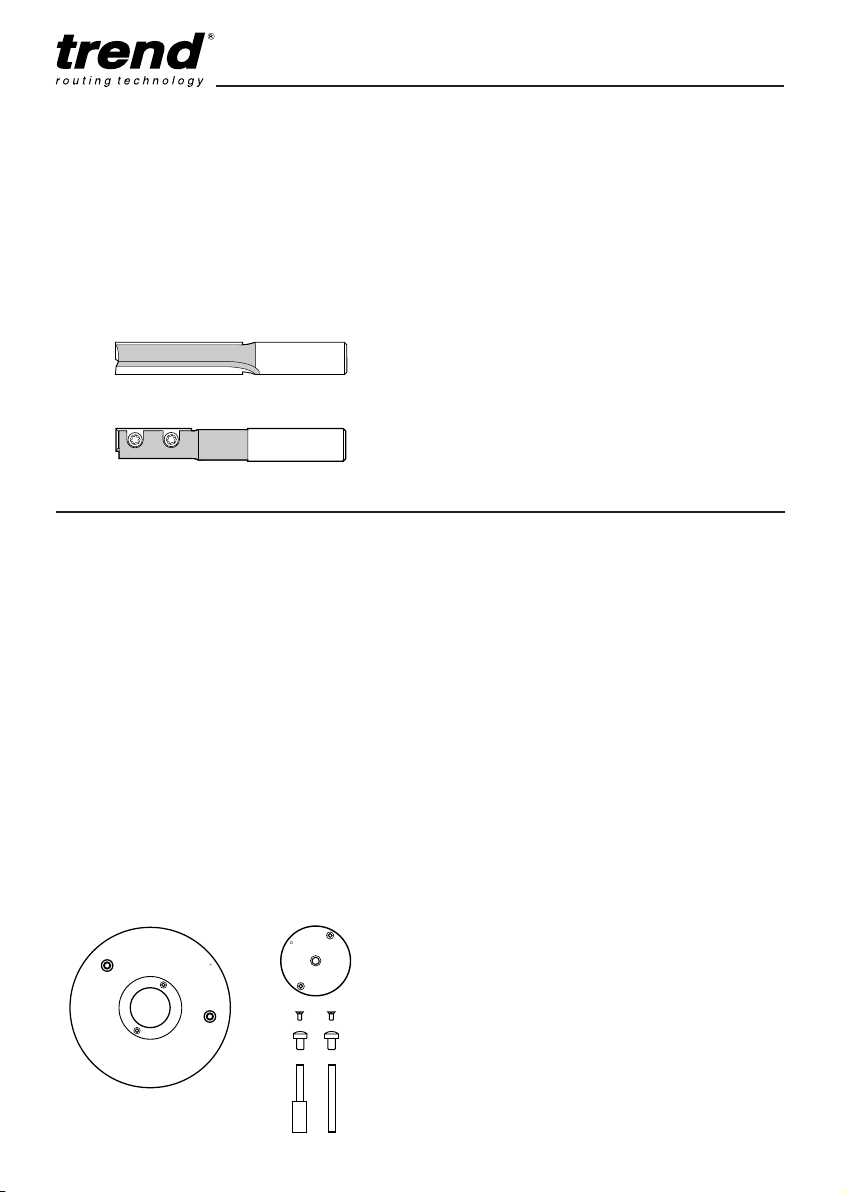
Recommended Cutters
A 12.7mm (1/2”) diameter cutter must be used,
which has a 50mm cutting reach and plunge cut
facility.
Router must be plunged in stages of maximum
8mm in one pass.
Description Order Ref.
Craft Range Cutter C153x1/2TC
As above with TC centre tip C153Dx1/2TC
Trade Range Cutter TR17x1/2TC
As above with TC centre tip TR17Dx1/2TC
Professional Range Cutter 3/83x1/2TC
As above with TC centre tip 3/83Dx1/2TC
As per 3/83 but with shorter shank
for Makita, Ryobi & Hitachi routers 3/83Mx1/2TC
Replaceable tip cutter RT/11x1/2TC*
Above cutter (with shorter shank)
for Makita, Ryobi & Hitachi routers RT/11Mx1/2TC*
Replacement blade (1 off) RB/A
Replacement blade (10 off) RB/A/10
*This cutter has a 30mm tip length but will cut to a
maximum depth of 50mm.
Order Ref. C153, TR17D, TR17, 3/83D, 3/83M
Order Ref. RT/11, RT/11M
Sub-base Sets
To obtain a perfect accurate close fitting joint, a
30mm guide bush must be used. The guide
bush must always be fitted concentric with the
cutter. This can be achieved using Trend subbases and 30mm outside diameter guide bush
ref. GB30.
Trend sub-bases have a central recess to allow
fitting of the Trend guide bush to most makes of
routers and are available ready to fit the most
popular makes.
Two types are offered GB/5 and UNIBASE.
All sub-bases contain screws, a line-up bush and
two line-up pins. The line-up pins and bush
ensure exact alignment of sub-base with router
spindle, when fitted with the relevant collet.
r o u t i n g t e c h n o l o g y
R
trend
GB/5 SUB-BASE
Fits following Router Models
Description Order Ref.
Elu MOF31,77,98,131,177(E),
Bosch GOF1600A & 1700ACE
DeWalt DW625EK
Felisatti R346EC
GB/5
Makita 3612BR & 3600B
Ryobi RE600N & R600N, RE601
GB/5/A
Hitachi M12V, M12SA & TR12
GB/5/D
Makita 3612C & 3612
GB/5/J
Bosch 1300ACE
GB/5/K
Freud FT2000E
AEG OFSE2000
Casals FT2000VCE
GB/5/L
Flex OFT3121VV,
Portercable 7539, 7519
GB/5/M
Felisatti TP246(E)
Festo OF2000E, Kinzo 25C46, Mafell L065E,
Metabo OF1612 & OFE1812,
Performance PRO1250,
Ryobi R500 & R502, Skil 1875U1,
Triton TRB001, Wadkin R500
GB/5/S*
*Please state model when ordering.
GB/5 Set comprises the following
Sub-base
GB10
170mm Ø x 8mm
1
/2” shank
line-up pin
1
/4” shank
line-up pin
t
r
e
n
d
1
0
m
m
R
ACCESSORIES
Page 6

Combi 1001
-5-
General instructions for fitting
sub-bases to Router
1. Fit line-up guide bush onto sub-base, with
screws supplied.
2. Fit 12.7mm (
1
/2”) shank line-up pin into collet
of router. Plunge router until pin projects
through base and lock plunge.
3. Locate guide bush and sub-base assembly
over protruding pin.
4. Line up fixing holes and fit screws.
5. Now tighten up screws.
6. Remove line-up bush and line-up pin.
Alignment should now be correct. Fit 30mm
guide bush and cutter.
7. Periodically check the sub-base is concentric
to the spindle of the router.
UNIBASE comprises the following
Fits following Router Models
Atlas Copco OFSE2000
Bosch GOF 1300ACE, 1600A, 1700ACE
Casals FT2000VCE
DeWalt DW625EK, 629
Draper R1900V
Elu MOF 31, 77, 98, 131, 177(E)
Faithfull FPPR2000E
Felisatti TP246(E), R346EC
Festo OF2000E
Freud FT2000E
Hitachi MI12V, M12SA, TR12
Metabo OF1612, OFE1812
Ryobi RE600N, R600N, RE601, R500, R502
Skil 1875U1
Wadkin R500
Description Order Ref.
Universal sub-base UNIBASE
t
r
e
n
d
3
0
m
m
R
GB30 30mm Guide Bush
Description Order Ref.
30mm guide bush to fit sub-bases GB30
UNIBASE
UNIBASE
170mm Ø
x 8mm
1
/4”+ 1/2”
shank
line-up pin
8mm +
12mm shank
line-up pin
1/2"
12mm
1/4"
8mm
16mm
Page 7
Combi 1001
-6-
100mm (4”) min.
throat depth
Panel Butt Connectors
Panel butt connectors are essential for
connecting worktops. They fit into the recess on
the underside of the worktop and are tightened
with a 10mm spanner. The jig has integral bolt
recess slots to allow the bolt recess to be cut in
the underside of the worktop, using the cutter.
The recess is elongated to allow easy access for
the spanner. Two types are offered, plastic
ended or metal ended. Plastic ended offer better
grip.
See the latest Trend Routing Catalogue for
details.
Description Order Ref.
Panel Butt Connectors plastic ends
(pack of 10) PC/10
(pack of 50) PC/50
(pack of 100) PC/100
(pack of 1000) PC/1000
Panel Butt Connectors metal ends
(pack of 10) PC/10/M
(pack of 50) PC/50/M
(pack of 100) PC/100/M
(pack of 1000) PC/1000/M
Biscuit Jointer for the Router
Worktops with inadequate support below them
need additional stability by biscuit jointing the
edges. The Trend biscuit jointing set for the
router together with the No.20 biscuits will
ensure worktops do not sag or warp in time, see
the latest Trend Routing Catalogue for details.
Description Order Ref.
Craft Range Biscuit Jointer Set C152x1/2TC
Trade Range Biscuit Jointer Set TR35x1/2TC
Professional Range Biscuit Jointer Set 342x1/2TC
No.20 Biscuits –
Quantity 100 BSC/20/100
1000 BSC/20/1000
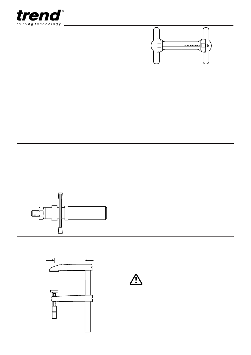
IMPORTANT!
Two heavy duty quick action or
gripper clamps with throats of
at least 100mm (4”) are
required to secure the jig to the
worktop. Whenever fast action
clamps are used, ensure they
do not foul the router path and
that they are securely tightened.
Gripper Clamp
Description Order Ref.
Gripper Clamps 6003010
(Two off required)
Page 8
Combi 1001
-7-
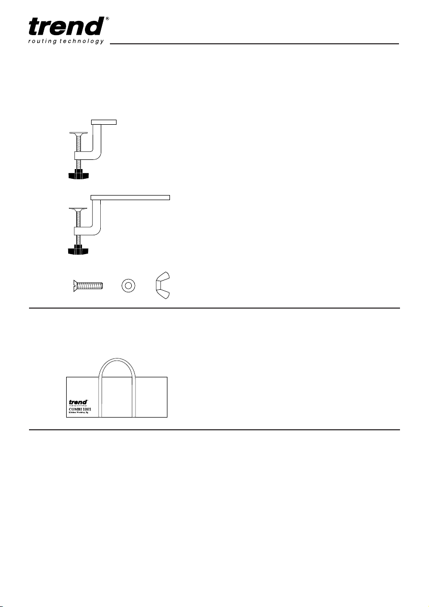
Bolt-on Clamps
Optional bolt-on clamps which fit directly onto
COMBI1001. Fixing Bolt Kits are required for
the clamps (1 off for PJ/CL/S and 2 off for
PJ/CL/L).
Fill and Seal
A solvent and silicone free coloured bonding
sealant used to seal worktop joints to prevent
moisture reaching the core material. Available
in nine colours, Fill and Seal can be intermixed
to match all laminate colour variations.
Sufficient to join four 700mm worktops, it is
supplied in 100ml flexible tubes, allowing it to
be squeezed into the joint prior to closing the
joint faces. Low odour and mould resistant the
sealant has a fast curing time of around 20
minutes.
Description Order Ref.
Short Clamp for COMBI1001 PJ/CL/S
(1 off required)
Long Clamp for COMBI1001 PJ/CL/L
(1 off required)
Fixing Bolt Kit for bolt-on clamps PJ/FBK
(3 off required)
Carry Case
Hard wearing carry case for protection. Allows
easier transportation of the COMBI1001.
Description Order Ref.
Carry Case for COMBI1001 CASE/1001
Description Order Ref.
Black Ash FS/100/BA
China Blue FS/100/CB
Champagne FS/100/CH
Deep Buff FS/100/DB
Empire Green FS/100/EG
Oyster White FS/100/OW
Pastel Grey FS/100/PG
Polar White FS/100/PW
Terracotta FS/100/TE
Pack of 9 colours FS/100/PACK
Page 9
Combi 1001
-8-
ASSEMBLY
Location Bush Identification
Three location bushes are used in different holes
in the jig to align the correct template aperture
for the application.
The holes are colour coded for easy
identification with dots as follows:
Green dot – Female Joint
Red dot – Male Joint
Blue dot – Mitre Corner
Yellow dot – Connector Recess
Grey dot – 45° Peninsular
White dot – Curved Peninsular
Black dot – Corner Radius
The jig has a colour coded key on its label for
quick reference.
Setting out the Joints
When cutting a joint ensure location bushes
contact the postformed edge of the worktop. For
certain joints the worktop will need to be inverted
so that all cuts are made into the postformed
edge, never out through it. When routing
worktops the balancing paper on the underside
may feather edge – this feather edge should be
removed with abrasive paper.
Location bushes are held in position by ‘O’ rings.
Insert the smallest end of the bush into the hole
by lightly pushing and turning at the same time.
If the bushes are tight use a lubricant on the ‘O’
ring. Ensure bushes are fully home before use.
When using the jig ensure location bushes do
not foul the workbench.
IMPORTANT!
In order to prevent breakout of
the laminate, rotation of the
cutter and feed direction must
always be into the postform
edge of the worktop.
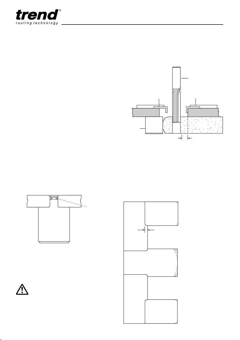
Margin Distance
Allow 8.5mm when cutting joints. Measure or
use a batten of this
thickness to aid
setting out.
O ring
Location bush
Cutter
Sub base
Guide bush
30mm Ø
Location
bush
Worktop
Template
8.5mm
23mm
Plan view
of joints
Right hand joint
Male
Female
Male
Female
Cut male with laminate down
Cut female with laminate up
Postform edge
The joint takes up 23mm, this should
be allowed for with extra material in the
length of the male worktop.
Male
Female
Postform edge
PENINSULA
Postform edge
Postform edge
Male
Female
Left hand joint
Cut male with laminate up
Cut female with laminate down
Page 10
Combi 1001
-9-
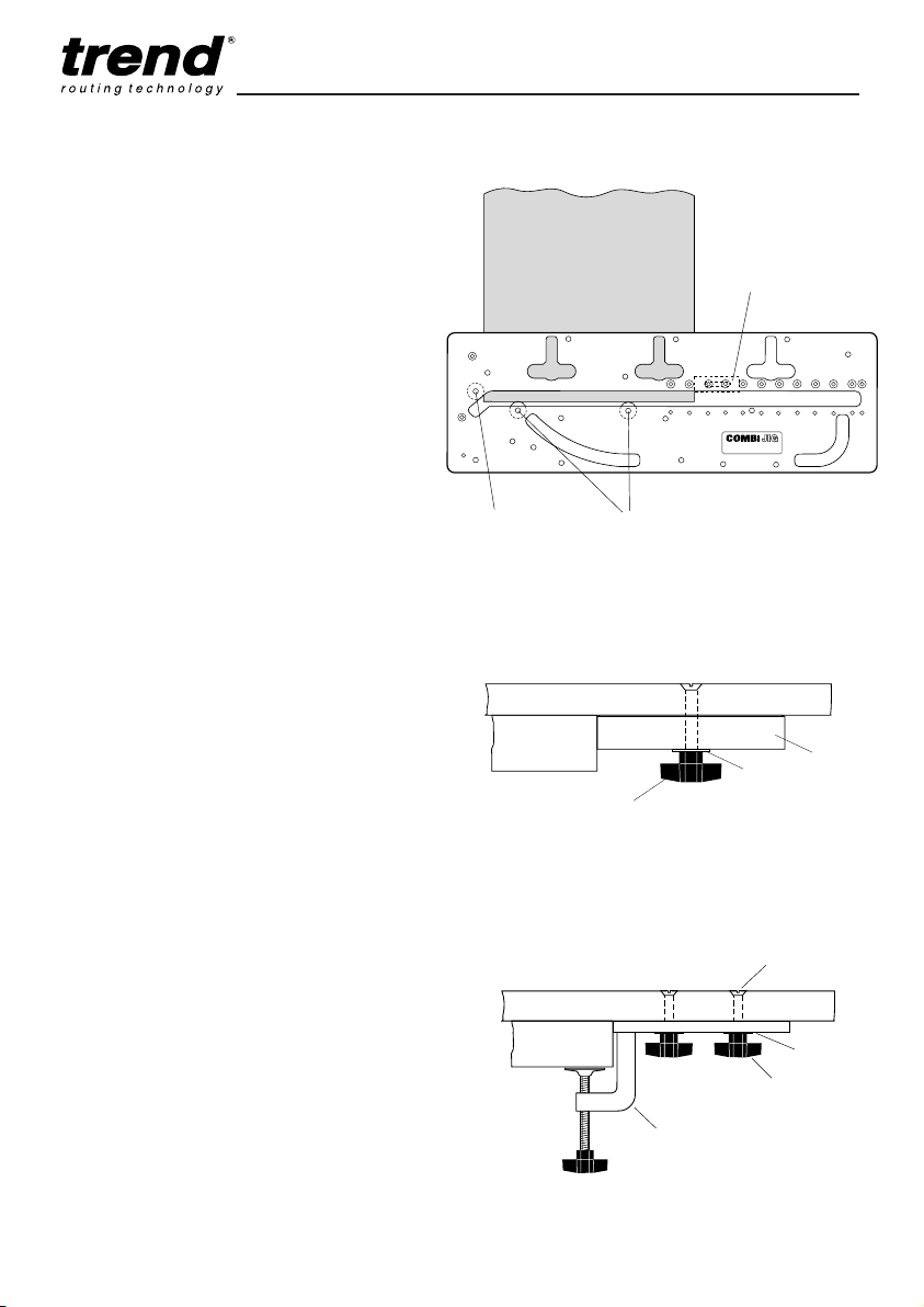
Length Stop Arrangement
OPERATION
Setting the Length Stop for the
Female Cut
Carry out the setting operation first:
I Fit bushes into Green dot location holes
and offer the jig to the worktop as shown.
Face marked Green dot must be
uppermost.
I Insert location bush in Red dot location
hole as shown, and position the jig across
the width of the worktop. Loosely fit the
length stop (or adjustable long clamp).
I Fasten length stop (or adjustable long
clamp) to template so that it traps the
template across the worktop between the
Red dot location bush and the stop (or
adjustable long clamp). Tighten up the
knob.
I Remove the bush from Red dot location
hole. The template is now set to cut the
correct length of joint.
I Some carcasses may have their backs
reduced which means in turn the worktop
width will be reduced. Please take this into
consideration when setting the length stop.
Setting the Length Stop
Location bush
(Red dot)
Postform edge
Length stop on
underside. Retained
with screw & knob
Location bushes
(Green dot)
Worktop
Length stop
Washer
Jig
Knob
Using Adjustable Clamp Accessory
PJ/CL/L
Worktop
Bolt
Washer
Jig
Knob
PJ/CL/L Clamp
Page 11
Combi 1001
-10-
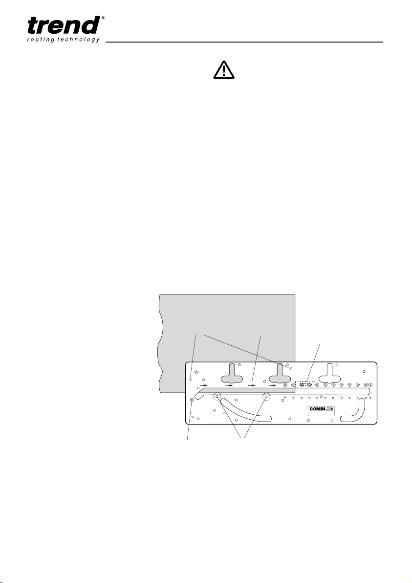
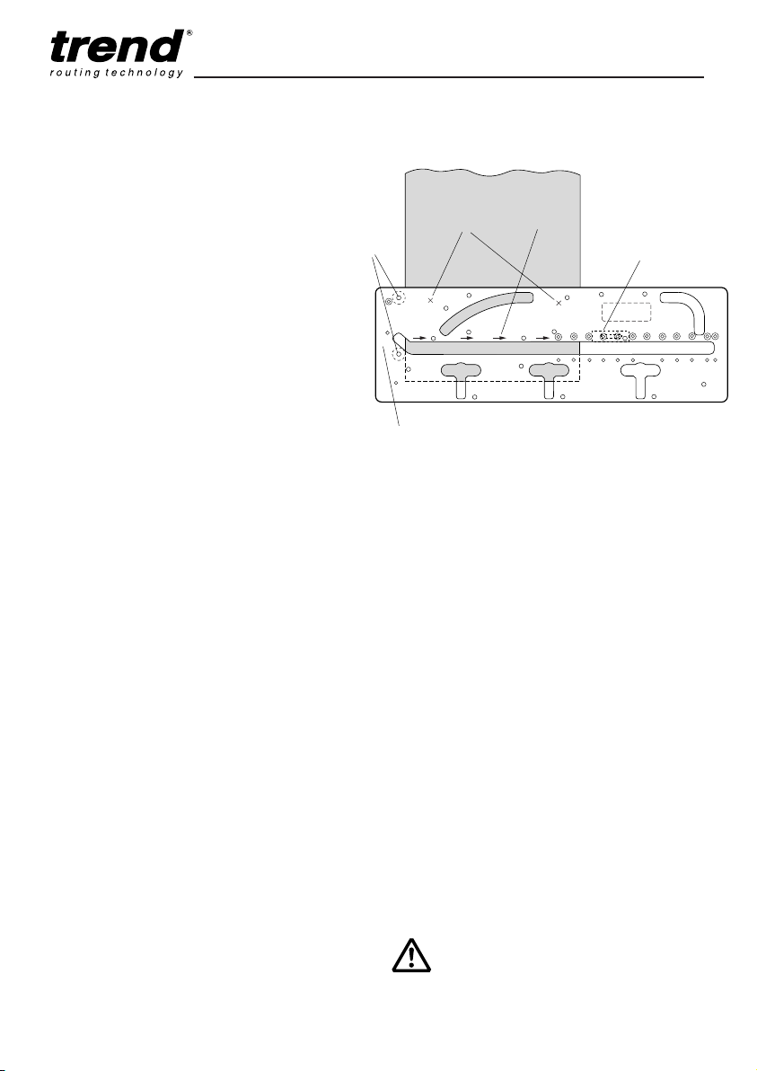
Female Joint
I Leave the two location bushes in holes
marked Green dot. (The Green dots must be
uppermost). Leave the length stop bush in
position.
I Place the template onto the worktop to be cut,
ensuring the location bushes are touching the
worktop. Now cramp securely in position
using two quick action clamps or the
accessory clamps ensuring they will not foul
the router path.
I Set cutter depth.
I Plunge router and cut joint in a series of
passes, feeding left to right.
IMPORTANT!
When cutting a joint, hold the
router guide bush hard against
the template and cut from left
to right. It is recommended that
the depth stops of the router
are used to set the depths of
cut. Several shallow passes of
the router should be made and
it is not necessary to lean
heavily on the router or the jig.
Allow the weight of the router
to rest on the part of the
template which is resting on
the worktop. Ensure router
remains parallel and upright at
all times.
Routing the female part of the Joint
Location bushes
(Green dot)
Postform
edge
Length stop (or accessory
clamp PJ/CL/L) set for correct
worktop width on underside
Quick action
clamp here
Router feed
direction
Optional short clamp
PJ/CL/S on underside
Page 12
Combi 1001
-11-
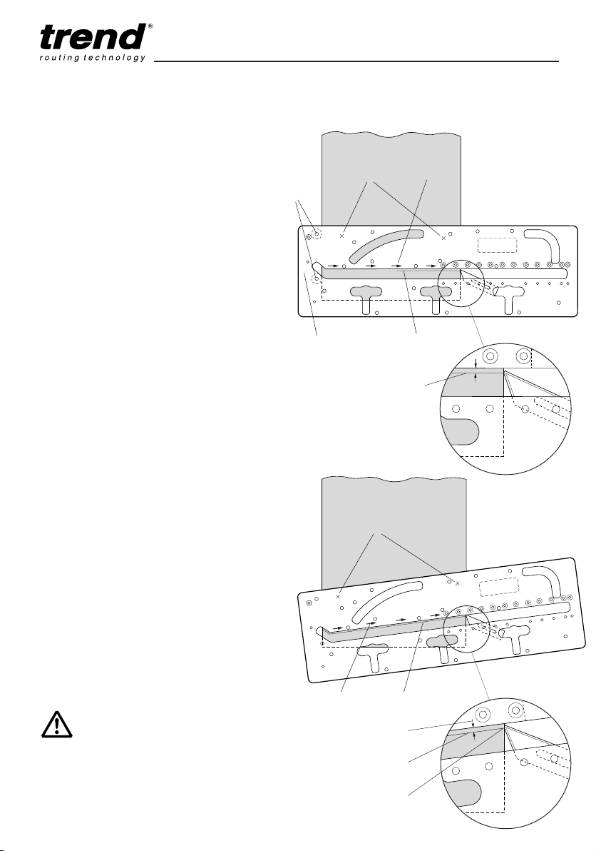
Male Joint
Depending on accessibility lay female
worktop into position on units. Lay male
worktop on top and support other end. Using
a pencil draw round the female cut onto the
male. If inaccessible lay female onto male.
Depending on a right or left hand joint, the
pencil line may need to be transferred on to
the other side. Due to the difference
between the cutter and the guide bush
diameters, the cutter path (or cut line) will be
8.5mm over from the edge of the template,
therefore either measure 8.5mm or use a
packing piece of this size to offset the
template by this amount to ensure the cutter
cuts along the pencil line.
The postformed edge of the worktop must
always be in contact with the location
bushes, this means that to cut a male right
hand joint, the worktop must be inverted.
Remembering to cut into the postformed
edge.
I Insert two location bushes into holes
marked Red dot. Face marked Red dot
must be uppermost.
I Place template across the width of the
worktop and clamp securely.
I Cut the male joint before finally cutting the
worktop to length. All cuts must be fed left
to right.
Routing the male part of the Joint
IMPORTANT!
Test fit the joints together,
abrasive paper may be required
to clean up the chipboard core.
Quick action
clamp here
Direction of
router travel
Location
bushes
(Red dot)
Optional accessory clamp
PJ/CL/L on underside, not
used as length stop
Optional accessory clamp
PJ/CL/S on underside
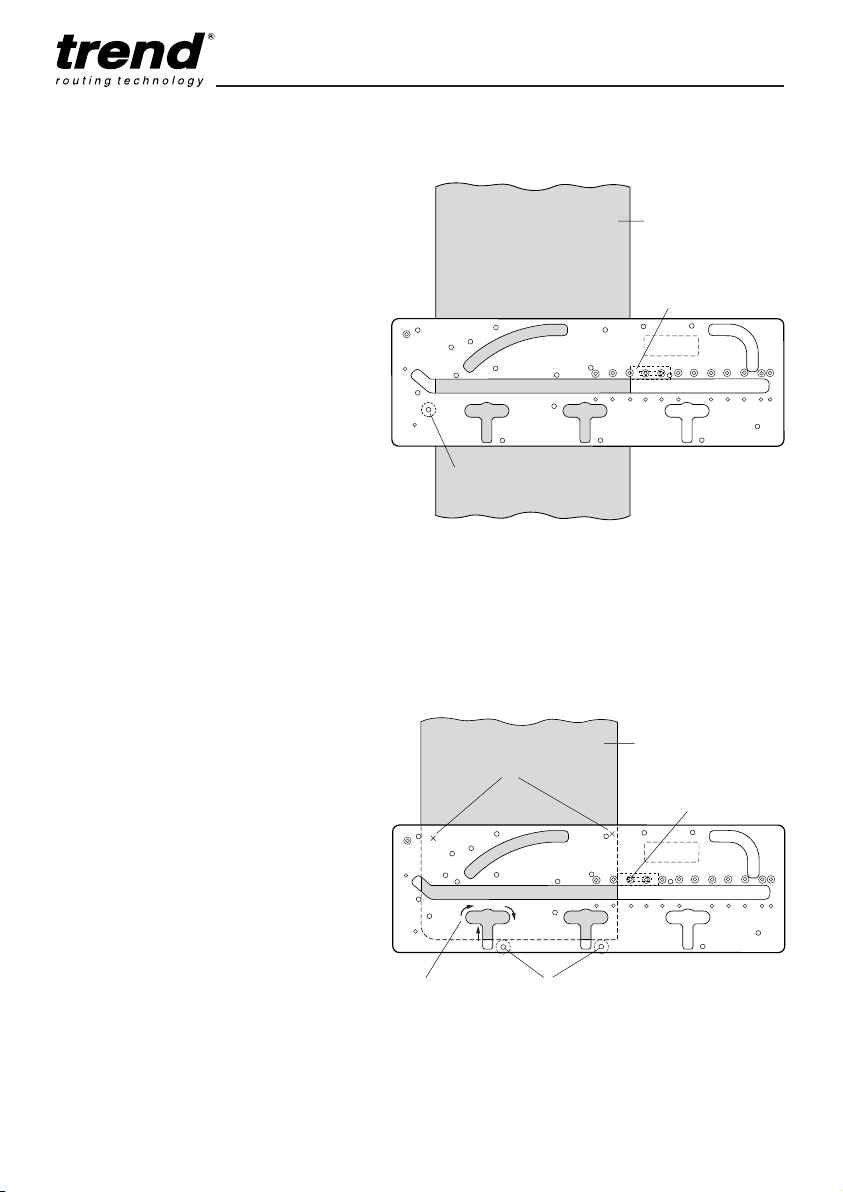
Out-of-square Joints (max. 3°)*
It may not be possible to position all joints at
90°, in this case it is the male part of the joint
that has to be adjusted.
The length stop has a mitred end which is used
to set up for an out-of-square joint up to 3°.
To mark out an out-of-square joint, first lay the
female worktop on the cupboard carcass in its
correct position. Next lay the male section of the
worktop on the carcass and on top of the female
section of the worktop. Support the other end of
the male worktop. Using a pencil and from
underneath the worktop mark around the female
joint onto the male section of the worktop, if
access is difficult lay the female worktop onto the
male worktop, support other end and mark with
pencil from above. This drawn line is the male
joint cut line.
Postform edge
*Please Note:
Out-of-square joints are possible, but the
finished joint will not be as good as a 90° joint.
Page 13
Combi 1001
-12-
I Insert both location bushes into Red dot
holes. Red dot face uppermost.
I Lay jig across the worktop, ensure the
location bushes touch the postform edge.
Clamp jig in position with quick action
clamps. Draw a line 8.5mm away from the
jig slot edge.
I With the mitred end of the length stop
facing towards the back of the worktop, as
shown. Fit the length stop onto underside
of jig by using the countersunk bolt,
washer and knob into one of the holes in
the jig. The bolt should be put into the jig
from above, do not tighten. Carefully
position the point of the length stop so that
it lines up with the 8.5mm margin pencil
line. When the correct position has been
obtained tighten bolt and knob sufficiently
to prevent length stop from moving.
I Remove location bushes.
I Lay jig with length stop set onto male work
top that is to be cut. Allowing for the
8.5mm margin and using the length stop
as a pivot point (pivot point on cut line)
position the jig so the jig slot edge is
parallel to the drawn pencil line. Re-check
positioning.
I Clamp jig to worktop securely using quick
action clamps.
I Remove length stop and bolt assembly as
these are for setting up only and are not
required when routing.
I Set cutter depth.
I Plunge router and cut the male joint,
feeding left to right in a series of shallow
passes, feeding left to right.
Cutting male
joint on out-ofsquare joints
Shown exaggerated
Setting up length stop for out-ofsquare joints
Parallel pencil line
8.5mm from jig slot edge
IMPORTANT!
After setting for out-of-square
joint the length stop must be
removed or it could come in
contact with the router cutter.
8.5mm margin
pencil line
Quick action
clamp here
Direction of
router travel
Optional accessory
clamp PJ/CL/S on
underside
Location
bushes
(Red dot)
Male joint cut line
Quick action
clamp here
Jig slot edge 8.5mm away
from male joint cut line
Direction of
router travel
Male joint on
cut line
Pivot point on male
joint cut line
Page 14
Combi 1001
-13-
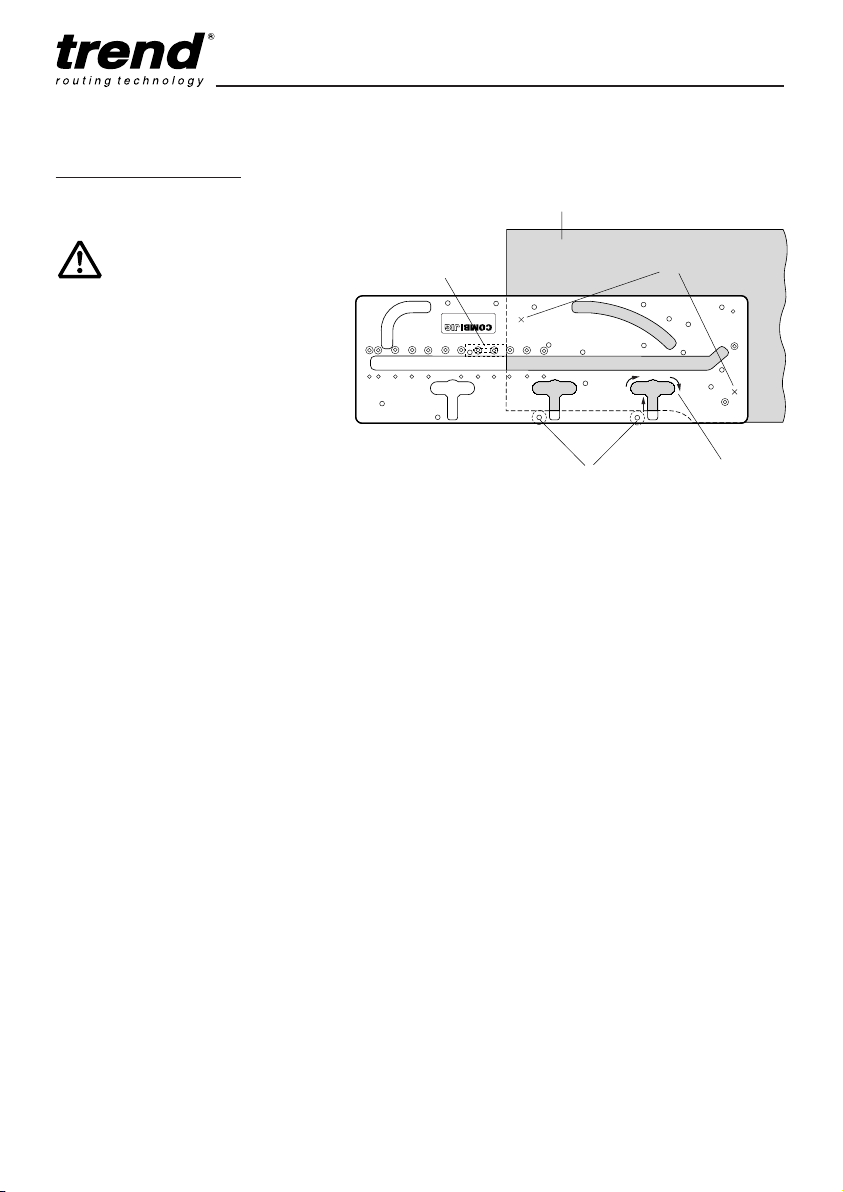
Cutting the Bolt Recesses
When the joint has been tested, proceed
as follows to cut the recess for panel butt
connectors on the underside of the
worktop. The same cutter and guide bush
are retained and used with the integral
bolt recess slots in the jig to produce the
recesses for the panel butt connectors.
To set the length stop (or adjustable
clamp) for both joint recesses, insert a
location bush in Blue dot location hole as
shown in diagram and lay template across
the width of the worktop. The diagram
shows for bolt recess in the male joint,
Yellow dot holes up. Fit length stop or
adjustable clamp as before. Ensure that
the stops are against the rear of the
worktop and not against the postform
edge. Remove setting bush and place
template on the underside of the worktop.
Insert the location bushes into the Yellow
dot holes as shown.
I The template will need to be inverted
when cutting some bolt recesses.
I Securely clamp jig to worktop.
I The bolt recesses should be
approximately 20mm deep although
this will depend upon the thickness of
worktop. Set the cutter depth.
I Repeat the set up procedure for the
female joint, however the location bush
and length stop (or adjustable clamp)
should be fitted on the opposite face of
the worktop Yellow dot holes down.
Setting bolt recess length stop
Location bush
(Blue dot)
Underside of worktop
Length stop (or accessory clamp
PJ/CL/L) on underside
Postform edge
(Continued on next page)
Routing the bolt recess in the
male part of the joint
Location bushes
(Yellow dot)
Direction of
router travel
Quick action
clamp here
Underside of worktop
Postform edge
Length stop (or accessory clamp
PJ/CL/L) on underside
Page 15
Combi 1001
-14-
Worktop Depth
Thickness Recess
30 22mm
40 28mm
IMPORTANT!
Best results are
achieved when the
centre line of the bolt
corresponds to the
centre line of the
worktop. Clamp jig
securely to worktop.
Routing the bolt recess in the
female part of the joint
Location bushes
(Yellow dot)
Direction of
router travel
Underside of worktop
Quick action
clamp here
Length stop (or accessory
clamp PJ/CL/L) on underside
Page 16
Combi 1001
-15-
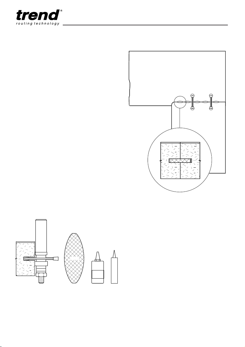
Strengthening the Joint
If the joint between the worktops is not
supported underneath, after some time the joint
may ‘sag’ and become misaligned; to reduce this
the joint should be reinforced with a loose
tongue or biscuit dowels. The biscuit jointing
cutter set Trend Ref. 342 can be used with a
portable router. The size of biscuit used should
be No. 20.
Ref. BSC/20/100 (100 biscuits)
Ref. BSC/20/1000 (1000 biscuits)
A 650mm worktop should have at least 5
biscuits.
Sealing the Joint
The cut edges of the joint should be coated with
a water-resistant adhesive, or sealant before
assembly, to prevent moisture seeping into the
core of the worktops, which would swell and
disfigure the worktop.
Use a fine grit abrasive paper to clean up the
torn wood chips of both mating surfaces. Lightly
run the abrasive paper along the edges to de-nib
the cut chipboard edge. This will ensure a tidy
joint is achieved.
Cutter Ref. 342
No.20
PVA
SEALANT
Waterproof
Biscuit
Underside View
Page 17
Combi 1001
-16-
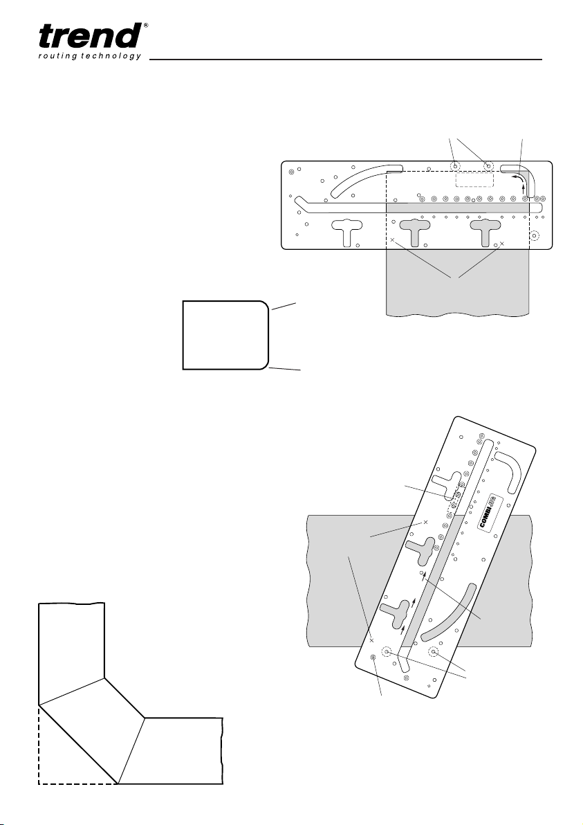
Routing the Mitre Corner Joint
Cut with
laminate
down
Cut with
laminate up
Cut with
laminate
down
Cut with
laminate up
Postform edge
Postform edge
Postform edge
Optional accessory
clamp PJ/CL/L on
underside
Quick action
clamp here
Postform edge
Direction of
router travel
Location bushes
(Blue dot)
Optional accessory
clamp PJ/CL/S on
underside
Corner Radius
Special Note: Due to the nature of this
particular edge laminate, the corner radius
will be more awkward to laminate.
Insert the three location bushes in holes
marked Black dot as shown opposite.
Locate the template on the worktop as
illustrated ensuring the location bushes are
touching the worktop edge. Clamp into
position with quick action clamps.
When cutting the radius hold the router guide
bush against the template radius. Feed left to
right.
It is recommended that
the router depth stops are
used and three or four
cuts are taken.
Cut with laminate
down
Cut with laminate
up
Routing the Corner Radius
Quick action
clamp here
Postform edge
Location bushes
(Black dot)
Direction of
router travel
Plan View of
Corner Joint
Cuts
22.5° Mitre Joint
I For the left hand part of the 22.5 mitre joint
fit bushes into holes marked with a Blue
dot. The Blue dot will be uppermost.
I Clamp jig using quick action clamps or
accessory clamps.
I When cutting, keep guide bush against
edge of template. Feed left to right into
the postform edge.
I For opposing joint keep bushes in the
same side.
I Repeat above operations for remainder
of joint.
Page 18
Combi 1001
-17-
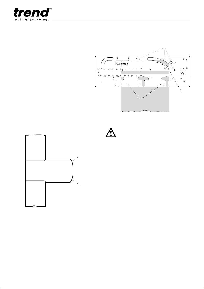
Curved Peninsular
Insert the three location bushes in holes
marked White dot as shown below.
Locate the template on the worktop as
illustrated ensuring that location bushes are
touching the worktop edge. Clamp into
position with quick action clamps.
When cutting the curved peninsular, hold the
router guide bush against the edge of the
template. Cut from left to right.
It is recommended that depth stops are used
and at least three or four cuts taken. White
discs must be uppermost when routing.
Quick action
clamp here
Postform edge
Location bushes (White dot)
Direction of
router travel
Cut with
laminate
down
Cut with
laminate
up
Postform edge
Postform edge
Postform edge
Postform edge
Peninsular
Peninsular End Cuts
Routing the Curved Peninsular
IMPORTANT!
In order to prevent break out of
the laminate, rotation of the
cutter and feed direction of the
router must always be into the
postform edge of worktop.
Page 19
Combi 1001
-18-
Guarantee
I The jig carries a manufacturers guarantee in
accordance with the conditions on the
enclosed guarantee registration card.
Recycling
I Jig, accessories and packaging should be
sorted for environmentally friendly recycling.
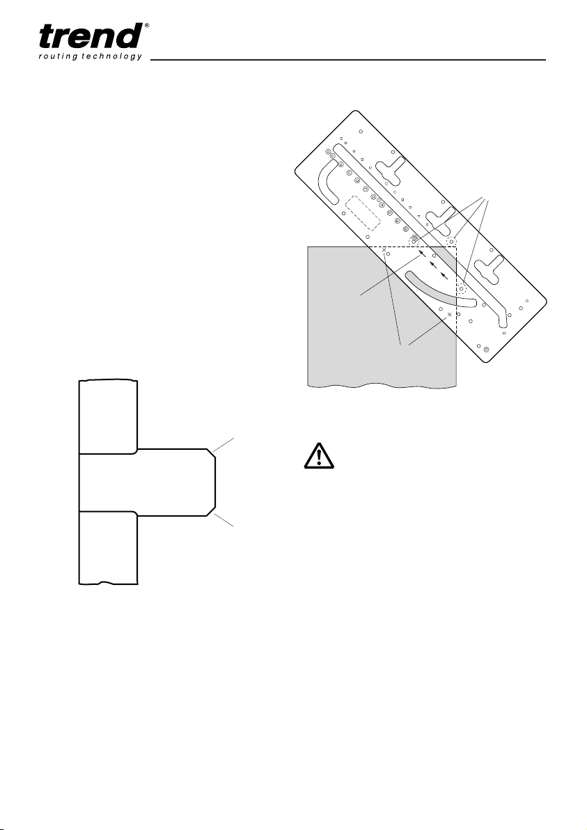
45° End Cut
Insert the three location bushes into holes
marked Grey dot as shown below.
Locate the template on the worktop as
illustrated ensuring that bushes are touching
the worktop edge. Clamp using two quick
action clamps.
It is recommended that depth stops are used
and three or four cuts taken. Cut from left to
right. Grey dot must be uppermost when
routing.
Routing the 45° End Cut
Quick action
clamp here
Postform
edge
Location bushes
(Grey dot)
Direction of
router travel
Cut with
laminate
down
Cut with
laminate
up
Postform edge
Postform edge
Postform edge
Postform edge
Peninsular
Peninsular End Cuts
IMPORTANT!
In order to prevent break out of
the laminate, rotation of the
cutter and feed direction of the
router must always be into the
postform edge of worktop.
Page 20
Combi 1001
-19-
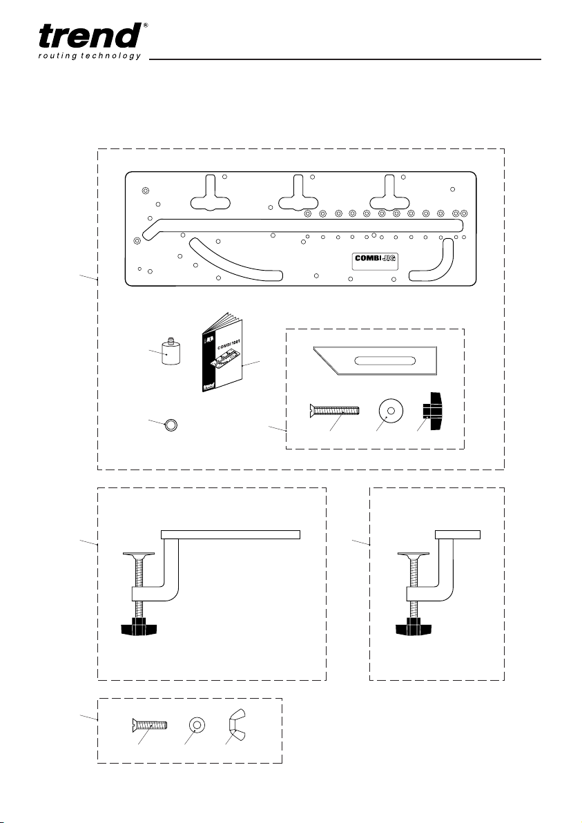
COMBI 1001
SPARE PARTS DIAGRAM
1
2
3
14
54 6
8
10
9
1211 13
7
v2.0 11/2000
Page 21

Combi 1001
-20-
COMBI 1001 - SPARE PARTS LIST v2.0 11/2000
Item Qty Description Ref.
1 1 Combi 1001 Jig COMBI/1001
2 3 Alloy Bush BUSH/1001
3 1 Length Setting Stop CJ/LSK
4 0 Machine Screw Csk M8 x 50mm slot WP-SCW/41
5 0 Washer 8.5mm x 32mm x 1.0mm WP-WASH/17
6 0 Knob M8 WP-KNOB/10
7 0 Combi Jig ‘O’ Ring Set for Bushes (pack of 5) CJ/ORS
8 1 Long Clamp PJ/CL/L
9 1 Short Clamp PJ/CL/S
10 1 Fixing Bolt Kit PJ/FBK
11 0 Machine Screw Csk M8 x 35mm slot WP-SCW/40
12 0 Washer WP-WASH/17
13 0 Wing Nut M8 WP-NUT/13
14 1 Manual MANU/1001
Page 22

Combi 1001
Fault Cause Remedy
I Joint does not fit correctly Cutter or guide bush is the Check concentricity of cutter
at the radius. incorrect diameter or location with guide bush. Cutter 12.7mm
bushes are not against diameter with 30mm diameter
worktop edge. guide bush. Ensure location
bushes touch worktop.
I The back edge of the joint Either the length stop or Check position of length stop
does not line up. template was in the incorrect and re-cut joints.
position, or the worktop has
not pushed up against the
length stop when the joint
was cut.
I When clamped together the The guide bush has drifted away Check with a straight edge
joint has irregular gaps. from the edge of the template which part of the joint is uneven
whilst cutting either part of the and re-cut (this can only be
joint, or wood chips in particle done on the male cut) ensuring
board have torn slightly. that the guide bush is kept
against the template by machining from left to right. Use
abrasive paper to remove torn
wood chips.
I Chipped laminate Can be caused by a blunt cutter Always use sharp cutters and
or removing too much material when cutting through the
at one pass or exiting out of laminate cut 3–4mm of material.
postform edge. Maintain correct feed direction,
to ensure cutter enters
postform edge.
I Jig slipping on material Clamps not secure or too deep Check clamps for wear. Clamp
a cut being made or cutter is securely, take shallow passes,
blunt. use a sharp cutter.
I Cut joints not square Router has tilted or operator Ensure jig is supported and do
has leaned heavily on router not push hard on router taking
causing jig flex. shallow passes. Ensure weight
of router is on supported part
of jig and that the router is
upright.
I Assembled joint not flush Worktop different thickness or Ensure worktop is same thick-
or bowed worktop not flat (cupped). ness and flat.
TROUBLE SHOOTING
Page 23

MANU/1001 v6.0
© Copyright Trend 2002. No part of this publication may be reproduced, stored or transmitted in any form without prior permission.
Our policy of continuous improvement means that specifications may change without notice. Trend Machinery and Cutting Tools
cannot be held liable for any material rendered unusable or any form of consequential loss. E&OE
RECYCLABLE
Trend Machinery & Cutting Tools Ltd.
Odhams Trading Estate St Albans Road
Watford WD24 7TR England
Enquiries: __________________0800 487363
Technical Support:____0044 (0) 1923 224681
Fax: ________________0044 (0) 1923 236879
Email:____________[email protected]
WWW: __________www.trendmachinery.co.uk
 Loading...