

Page 1

MODEL 6804
owner’s manual supplement
Page 2
SLASH 4x4 PLATINUM EDITION
Introduction
Thank you for choosing the Traxxas Slash 4x4 Platinum Edition.
We believe you have purchased the most technologically
advanced, track-ready R/C short-course truck available. Slash
4x4 proudly demonstrates Traxxas’ passionate commitment to
innovation, ultimate performance, and unmatched engineering.
Slash 4x4’s advanced design takes short-course performance to
a higher level. Already engineered to win, Slash 4x4 Platinum
Edition pushes the performance envelope even further with
accessories developed for competition.
We know you’re excited about getting your new Slash 4x4 on
the track, but it’s very important that you take some time to
read through the Owners Manual included with your model,
in addition to this supplement. The manual contains all the
necessary set-up, tuning, and maintenance procedures that
allow you to unlock the incredible performance and adjustment
potential that Traxxas engineers designed into the Slash 4x4.
Even if you are an experienced R/C enthusiast, it’s important to
read and follow the procedures in this manual. Slash 4x4 utilizes
proprietary technology that you may not be familiar with.
We want you to feel confident that you own the best performing
truck on the market and that it is backed by a team of
professionals who aim to provide the highest level of factory
support possible. The Slash 4x4 Platinum Edition is about
experiencing total performance and satisfaction, not just with
your truck, but with the company that stands behind it. We
truly want you to enjoy your new Slash 4x4! Thank you again for
going with Traxxas.
Included with Slash 4x4 Platinum Edition
In addition to Slash 4x4’s many standard performance features,
your model includes the following PLATINUM EDITION upgrades:
• Sealed, silicone-filled center differential
• Big Bore aluminum competition shocks
• Titanium-Nitride shock shafts
• Blue-anodized aluminum front axle carriers
• Blue-anodized aluminum rear axle carriers
• Blue-anodized aluminum C-Hubs
• Front and rear swaybars
• Soft, S1-compound BFGoodrich® Mud-Terrain™ T/A® licensed tires
• Clear body with window masks
• Platinum Edition decal sheet
Required to Complete Your Model
The 6808 Slash 4x4 manual included with your Platinum Edition
model references the TQ2.4GHz transmitter and receiver, Traxxas
Power Cell 7-cell battery, and charger. These components
are not included with your model. To complete the Slash 4x4
Platinum Edition for operation, you will need; polycarbonatecompatible paint; two-channel transmitter with mini receiver;
battery with Traxxas High-Current Connector (6-7 cell NiMH, 2 or
3-cell LiPo); and a charger. You MUST use a LiPo-specific charger
with LiPo batteries.
Traxxas Support
Traxxas support is with you every step of the way.
Read below to find out how to contact us and
what your support options are. If you have any
questions about your Slash 4x4 or its operation,
call the Traxxas Technical Support line toll-free
at: 1-888-TRAXXAS (1-888-872-9927)* Technical
support is available Monday through Friday from 8:30 am to
9:00 pm central time. Technical assistance is also available at
Traxxas.com. You may also e-mail customer support with your
question at [email protected]. Join hundreds of Traxxas R/C
enthusiasts in our online community at Traxxas.com. Traxxas
offers a full-service, on-site repair facility to handle any of your
Traxxas service needs. Maintenance, replacement parts, and
accessories may be purchased directly from Traxxas by phone
or online at BuyTraxxas.com. You can save time, along with
shipping and handling costs, by purchasing replacement parts
from your local dealer. Do not hesitate to contact us with any
of your product support needs. We want you to be thoroughly
satisfied with your new Slash 4x4!
Installing your Receiver
This model requires the installation of a radio system. Slash 4x4’s
watertight, o-ring sealed receiver box is designed to accept
“mini“ and “micro” receivers with maximum dimensions of
48mm long x 31mm wide x 17mm tall (1.9 x 1.2 x 0.6”). Follow
the steps below to install your receiver and maintain the receiver
box’s watertight seal.
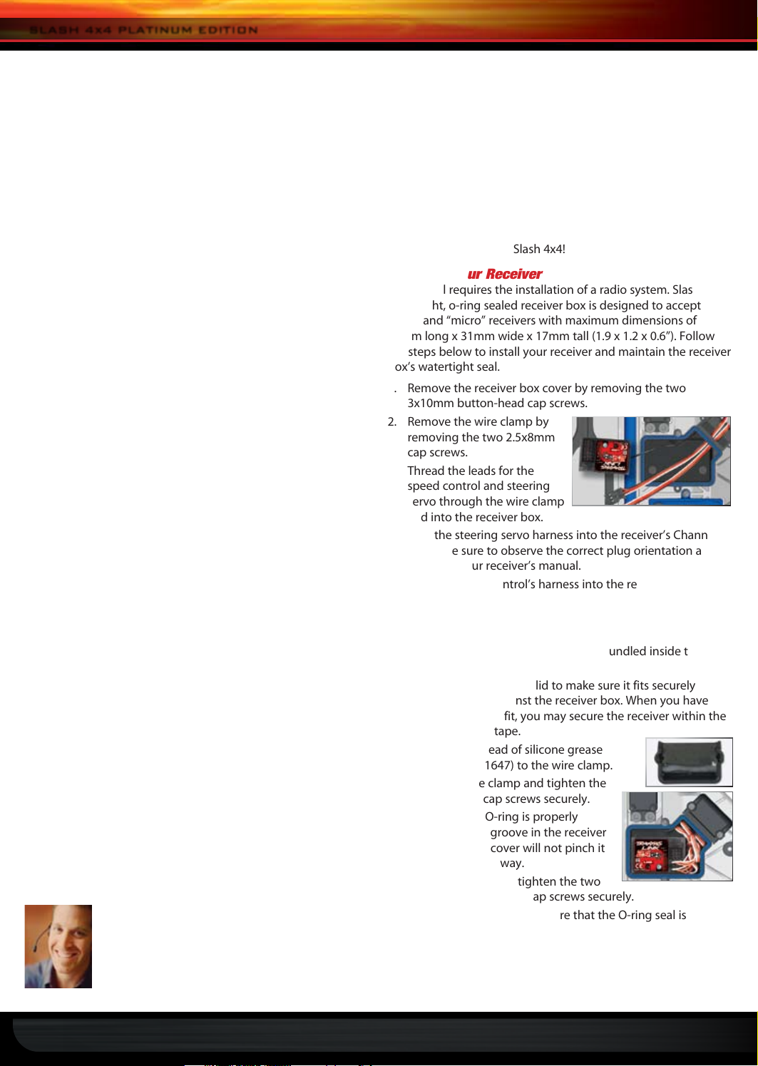
1. Remove the receiver box cover by removing the two
3x10mm button-head cap screws.
2. Remove the wire clamp by
removing the two 2.5x8mm
cap screws.
3. Thread the leads for the
speed control and steering
servo through the wire clamp
and into the receiver box.
4. Plug the steering servo harness into the receiver’s Channel
1 port. Be sure to observe the correct plug orientation as
shown in your receiver’s manual.
5. Plug the speed control’s harness into the receiver’s
Channel 2 port.
6.
Route the receiver antenna out of the box, through the wire clamp.
7. Arrange the wires neatly using the wire guides in the
receiver box. The excess wire will be bundled inside the
receiver box.
8. Test-fit the receiver box lid to make sure it fits securely
and completely against the receiver box. When you have
confirmed proper fit, you may secure the receiver within the
box using servo tape.
9. Apply a small bead of silicone grease
(Traxxas part #1647) to the wire clamp.
10. Install the wire clamp and tighten the
two 2.5x8mm cap screws securely.
11. Make sure the O-ring is properly
seated into the groove in the receiver
box so that the cover will not pinch it
or damage it any way.
12. Install the cover and tighten the two
3x10mm button-head cap screws securely.
13. Inspect the cover to make sure that the O-ring seal is
not visible.
2 • TRAXXAS
Page 3
SLASH 4x4 PLATINUM EDITION
Setting Up the Antenna
1. Thread the antenna wire into
the supplied antenna tube (the
antenna tube can be found in the
documents bag).
2. Insert the base of the tube into the
antenna mount. Take care not to crimp
the antenna wire.
3. Using the supplied 1.5mm “L” wrench,
thread the 1.5mm set screw into the
opening next to the antenna. Tighten the set screw until it is
flush with the top of the opening.
4. If necessary, fold the top of the antenna wire over the top of
the antenna tube. Slide the antenna tip onto the top of the
antenna tube. Do not cut or shorten the antenna wire.
5. The receiver antenna installation is complete.
Programming the VXL-3s Speed Control
The Slash 4x4 is equipped with the high-performance Velineon
brushless power system. Before operating your model, you
will need to calibrate the speed control to your transmitter, as
described below. The Velineon VXL-3s speed control also features
three driving profiles and Low-Voltage Detection for use with
lithium polymer (LiPo) batteries. Note that the speed control has
been adjusted at the factory specifically for the Platinum Edition,
using the following settings:
Driving Profile 1: Sport Mode - This profile enables full reverse
throttle control for maximum versatility and fun with your Slash
4x4. If you plan to race your Slash 4x4, be aware that most tracks
do not allow the use of reverse in competition. If your track
does not allow reverse, follow the steps on page 17 of the Slash
4x4 Owner’s Manual to select profile 2, Race Mode. Race Mode
eliminates reverse, but still gives fully proportional braking control.
Low-Voltage Detection: ACTIVATED - This is the required
setting for use with LiPo batteries. When switched on, the speed
control’s LED will glow green, indicating Low-Voltage Detection
has been enabled. The Low-Voltage Detection circuitry
constantly monitors the battery voltage. When the battery
voltage begins to reach the minimum recommended discharge
voltage threshold for LiPo battery packs, the VXL-3s will limit
the power output to 50% throttle. When the battery voltage
attempts to fall below the minimum threshold, the VXL-3s will
shut down all motor output. The LED on the speed control will
slowly blink red, indicating a low voltage shutdown. The VXL-3s
will stay in this mode until a fully charged battery is connected.
If you wish to operate your model using a NiMH battery,
Low-Voltage Detection may be disabled to achieve maximum
run time. Page 16 of the Owner’s Manual explains how to
disable Low-Voltage Detection. When the speed control
is turned on, its LED will glow red, indicating Low-Voltage
Detection is disabled. Never use LiPo batteries while Low-
Voltage Detection is disabled.
VXL-3s Setup Programming
(Calibrating your ESC and transmitter)
Read through all of the programming steps before you begin. If
you get lost during programming or receive unexpected results,
simply unplug the battery, wait a few seconds, plug the battery
back in, and start over.
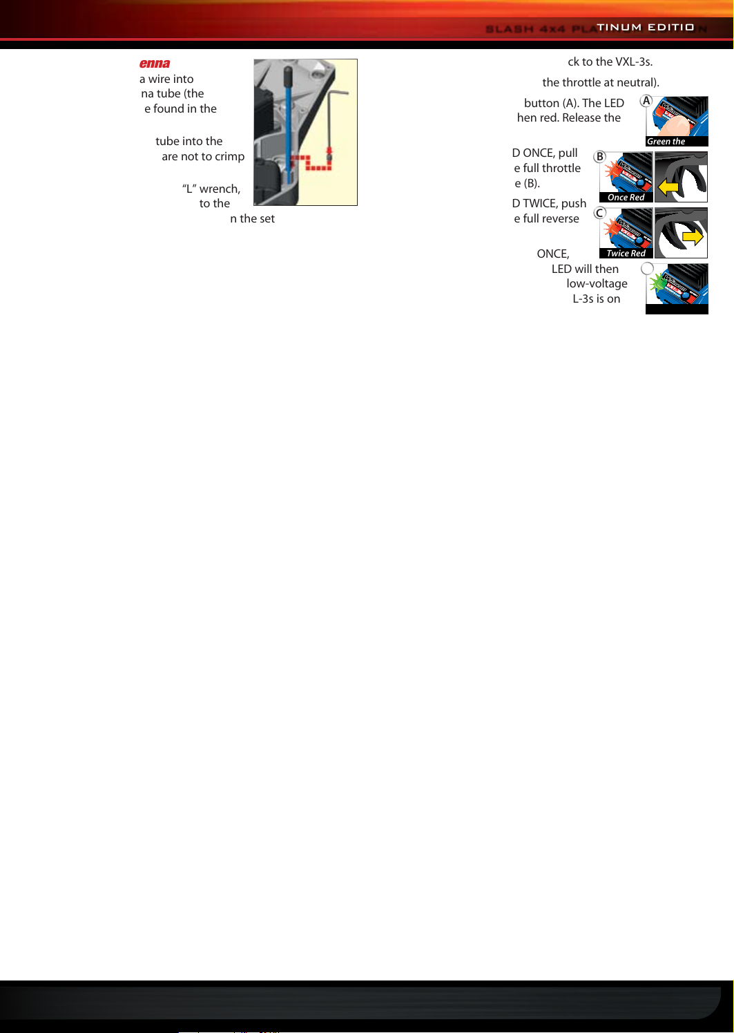
1. Connect a fully charged battery pack to the VXL-3s.
2. Turn on the transmitter (with the throttle at neutral).
3. Press and hold the EZ-Set button (A). The LED
A
will first turn green and then red. Release the
EZ-Set button.
4. When the LED blinks RED ONCE, pull
B
Green then Red
the throttle trigger to the full throttle
position and hold it there (B).
5. When the LED blinks RED TWICE, push
the throttle trigger to the full reverse
Once Red
C
and hold it there (C).
6. When the LED blinks GREEN ONCE,
programming is complete. The LED will then
Twice Red
D
shine green or red (depending on low-voltage
detection setting) indicating the VXL-3s is on
and at neutral (D).
Once Green
Tuning and Maintaining the Shocks
Slash 4x4 features high-performance Big Bore shocks that utilize
friction-reducing titanium nitride shafts and hard-anodized
bodies with Teflon-coated bores to provide the ultimate in
precise damping control. The shocks are filled with 50W silicone
fluid in the front and 40W fluid in the rear. You may wish to install
lower-viscosity (“thinner”) or higher-viscosity (“thicker”) fluid to
alter damping performance to suit your track, terrain, or driving
style. Damping can also be altered by changing the pistons inside
the shocks.
Whenever you rebuild your shocks, or make any changes to the
pistons, springs or oil, always make changes to them in pairs
(front or rear). Piston selection depends on the range of oil
viscosities that you have available. For example, using a two-hole
piston with a lightweight oil will, at one point, give you the same
damping as a three-hole piston with heavier oil. We recommend
using the two-hole pistons with a range of oil viscosities from
10W to 50W (available from your hobby shop). The thinner
viscosity oils (30W or less) flow more smoothly and are more
consistent, while thicker oils provide more damping. Use only
100% pure silicone shock oil to prolong seal life.
Lower-viscosity fluid (lower oil weight #) = less damping force
More or larger piston holes = less damping force
In general, less damping is used on tracks or surfaces that
have lots of small bumps and irregularities that require
the shocks to extend and compress very rapidly. Reducing
damping allows the shocks to rebound more quickly after an
impact, so the shocks will be able to absorb the next impact
and allow the tires to better maintain contact with the racing
surface. Reducing damping force can also help increase
traction on “loose” or slippery surfaces.
Higher-viscosity fluid (higher oil weight #) = more damping force
Fewer or smaller piston holes = more damping force
In general, more damping is used on tracks that have large
bumps and jumps that require the shocks to absorb hard
impacts. Increased damping helps slow the compression rate to
better dissipate impact energy and help prevent the shocks from
bottoming out. Increased damping force can also help “loosen
up” your truck if you are racing on a high-traction surface and
prefer less grip to help you carry speed through corners.
TRAXXAS • 3
Page 4
SLASH 4x4 PLATINUM EDITION
2362
2742X
5525
5525
2742X
2669
2667
2664 2666
2668
2668
2668
2668
6857
6858
2668
2668
1664T
1664T
1765
2667
1765
2362
2669
2665
Stiffer
Softer
Shock Disassembly
The shocks must be removed from the vehicle and disassembled
to change the pistons. Use the shock exploded views included
with the model to aid in the assembly process.
1. Remove the spring and lower spring retainer from the shock.
2. Remove the shock cap (A) and empty the shock body of
shock oil.
3. Use side cutters to grip the shock shaft just above the rod end
(B). Unthread the rod end from the shock shaft.
4. Remove the shock shaft with piston from the shock body out
through the top of the shock body.
5. Use the corner of the tip of a small, bladed screwdriver
to remove the E-clip that secures the piston. Wear eye
protection in case the clip pops off. Tip: work beneath a rag
to catch the clip if it pops off.
Front Assembly Rear Assembly
sway bar travel in both unloaded and loaded suspension
conditions. Always adjust the left and right sway bar links
equally to prevent suspension tweak.
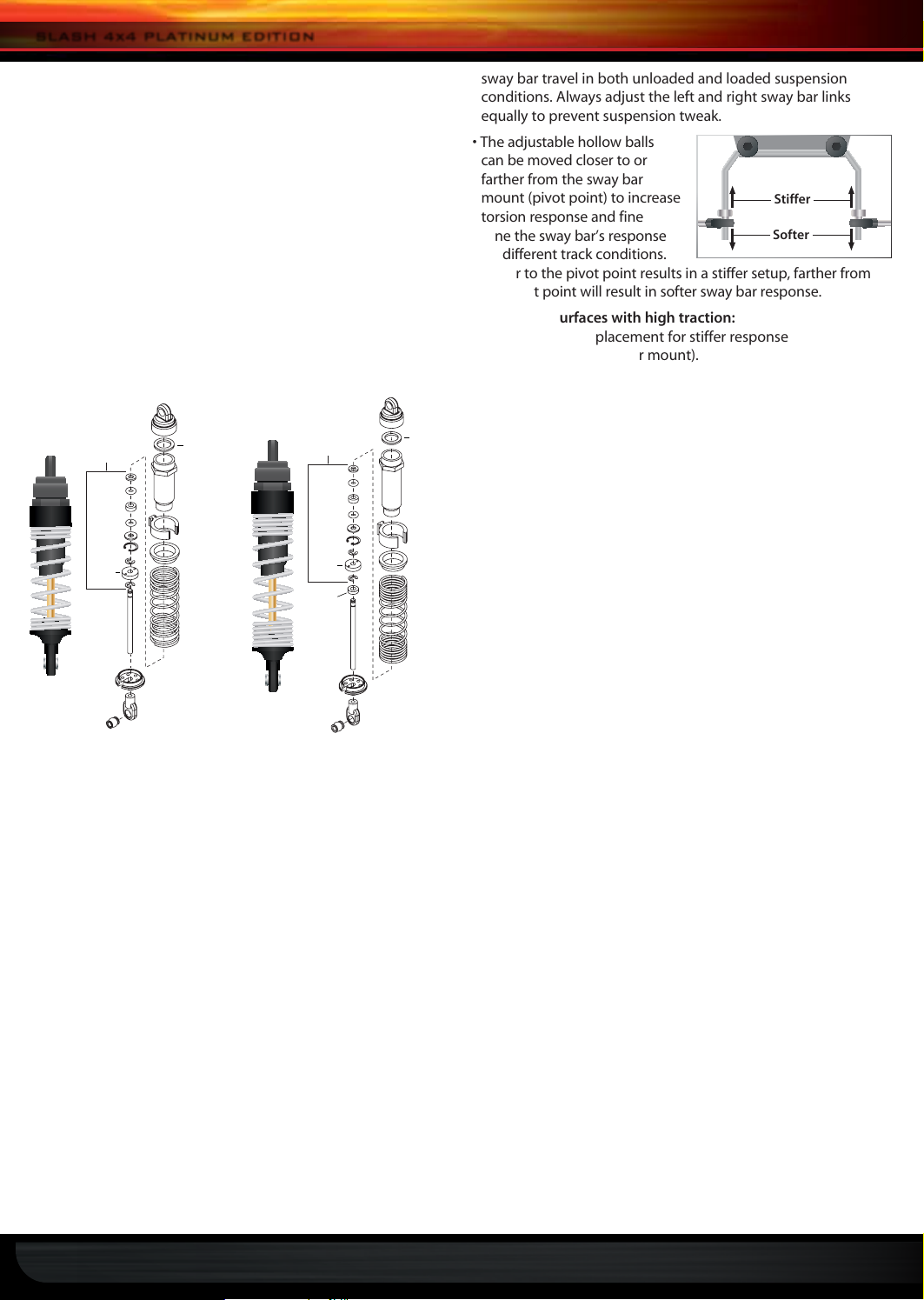
• The adjustable hollow balls
can be moved closer to or
farther from the sway bar
mount (pivot point) to increase
torsion response and fine
tune the sway bar’s response
for different track conditions.
Closer to the pivot point results in a stiffer setup, farther from
the pivot point will result in softer sway bar response.
For smooth surfaces with high traction:
• Adjust linkage placement for stiffer response
(closer to the sway bar mount).
For rough surfaces with low traction:
• Adjust linkage placement for softer response
(farther from the sway bar mount).
To reduce understeer (pushing in corners):
• Adjust front linkage placement for softer response
(farther from the sway bar mount).
• Adjust rear linkage placement for stiffer response
(closer to the sway bar mount).
To reduce oversteer (loose in corners):
• Adjust front linkage placement for stiffer response
(closer to the sway bar mount).
• Adjust rear linkage placement for softer response
(farther from the sway bar mount).
Shock Assembly
1. Replace the stock piston with desired optional piston.
2. Slide the E-clip onto the shaft. Squeeze it into place using
needle-nose pliers.
3. Lubricate the threads of the shock shaft and insert the shock
shaft assembly through the shock body until the piston
bottoms out.
4. Grip the shaft close to the threads with needle nose pliers or
side cutters and thread the rod end onto the shock shaft until
the rod end bottoms out.
5. Fill the shock with new silicone shock oil up to the top of the
shock body. Slowly move the piston up and down (always
keeping it submerged in oil) to release the air bubbles. Let
the shock sit for a few minutes to allow any remaining air
bubbles to surface.
6. Slowly thread the upper cap with the installed shock bladder
onto the shock body. The excess oil will bleed out of the small
hole in the shock cap. Tighten the shock cap until snug.
7. Reinstall the spring and lower retainer.
Sway Bar Settings and Adjustments
• Adjust the sway bar links so the sway bars are level (parallel
to the ground) when the truck is on the ground and the
suspension is at rest (normal ride height). This allows equal
Tuning the Center Differential
The center differential allows the power from the motor to be
transferred to the front and rear differentials independently from
one another. When the rear wheels are under more load than the
front wheels, more power will be transmitted to the front wheels.
This is very beneficial on rough terrain and makes hard acceleration
from low speeds easier to control by keeping the nose down.
The center differential is assembled with 100K differential lube
from the factory. This viscosity will be a good base point for
most conditions. Thinner fluid will transfer power more easily
than thicker fluid. Try thinner fluid on extremely rough and slick
surfaces, and thicker fluid on very smooth and high-bite surfaces.
Traxxas offers silicone differential fluid in a variety of viscosities:
Part #5135: 10K Part #5136: 30K Part #5137: 50K
Part #5130: 100K Part #5039: 500K
Follow these steps to remove and refill the differential:
1. Remove the two 4x12 button-head cap screws from the top
of the chassis.
2. Remove the two 4x12 button-head cap screws from the
bottom of the chassis.
3. Pull the rear suspension assembly away from the chassis.
4. Remove the center differential by pulling it away from the
rear gearbox.
5. Remove the four 2.5x10mm screws from the differential case
and carefully pull the diff case halves apart. Work over a towel
to collect any fluid that drips from the differential.
6. Drain the fluid from the differential. You may wish to remove
the spider gears from the differential to make this easier.
4 • TRAXXAS
Page 5
SLASH 4x4 PLATINUM EDITION
7. Place the spider gears back into the diff case, if you removed
them. Fill the diff case with fluid until it the spider gears are
submerged half way.
8. Rejoin the diff case halves, using care to align the screw
holes. Be sure the rubber gasket is in place, or the differential
may leak.
9. Install the 2.5x10mm screws and tighten securely.
10. Reinstall the differential by reversing steps 1-4.
Basic and Advanced Suspension Tuning
The Slash 4x4 main manual includes additional tuning
information to help you get the most performance from your
model. Suspension tuning basics (Toe-in, Camber, and Shock
Position) are covered on page 20. Advanced tuning techniques
(Camber Gain, Bump-steer Correction, and Roll Centers) are
discussed on page 24.
Adjusting Rear Toe-In
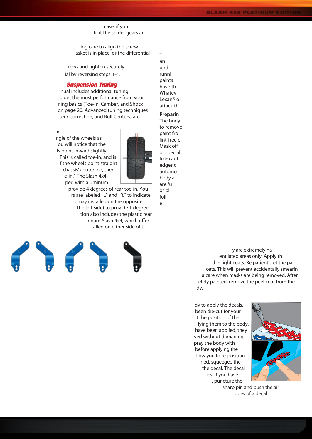
Toe-in refers to the angle of the wheels as
viewed from above. You will notice that the
Slash 4x4’s rear wheels point inward slightly,
which aids in stability. This is called toe-in, and is
measured in degrees. If the wheels point straight
ahead, parallel with the chassis’ centerline, then
the wheels have “zero toe-in.” The Slash 4x4
Platinum Edition is equipped with aluminum
rear stub axle carriers that provide 4 degrees of rear toe-in. You
will note that the axle carriers are labeled “L” and “R,” to indicate
left and right. The axle carriers may installed on the opposite
sides (L on the right side, R on the left side) to provide 1 degree
of toe-in. Slash 4x4 Platinum Edition also includes the plastic rear
stub axle carriers as used on the standard Slash 4x4, which offer
2.5 degrees of toe-in. They can be installed on either side of the
truck, they are not left/right specific.
Aluminum axle carriers
installed as labeled:
4 degrees toe-in
Aluminum axle
carriers reversed:
1 degree toe-in
Plastic axle carriers
(not L/R dependent):
2.5 degrees toe-in
0°
4°
Painting the Body
Note: Please read this entire section and plan your paint job
before beginning.
Buying Paint
The body supplied with your model is molded from lightweight
and durable clear polycarbonate. It should be painted on the
underside so that the color will not be scratched off while
running. The best way to paint the body is by using thinned
paints sprayed through an airbrush or spray gun. If you do not
have these tools, the next best way is using spray can paints.
Whatever paint you use, be sure that it is made for painting
Lexan® or polycarbonate. Other types of paints and solvents can
attack the body material and cause it to appear foggy.
Preparing the Body
The body must be washed thoroughly with dish soap and water
to remove any grease or oil (i.e. fingerprints) which may keep the
paint from adhering to it. Dry the body completely with a soft,
lint-free cloth. Use the supplied masks to mask the windows.
Mask off any stripes or custom effects with either masking tape
or special tape made for striping. This special tape is available
from automotive paint supply stores and will provide sharper
edges than masking tape. For easy, custom-colored striping,
automotive pin-striping tape can be applied to the inside of the
body and painted over. Be sure that all of your tape and masks
are fully pressed down (burnished) so that the paint will not run
or bleed underneath. Usually, the darker colors are painted first,
followed by the lighter colors. If your paint scheme would be
easier to mask by covering the dark areas and spraying them
last, be sure the lighter colors are opaque enough to prevent
the darker color from showing through. Lighter colors can be
backed with silver to help make them opaque.
Spraying the Body
Read the directions on your bottle or can of paint and shake,
mix, or thin the paint, as required. It is very important to avoid
breathing the paint vapors, as they are extremely harmful. Spray
the paint outdoors in well-ventilated areas only. Apply the paint
to the body sparingly and in light coats. Be patient! Let the paint
dry fully in between coats. This will prevent accidentally smearing
wet paint. Take extra care when masks are being removed. After
the body is completely painted, remove the peel coat from the
outside of the body.
In general, increasing toe-in improves stability, while reducing
toe-in may help “loosen up” the truck’s handling to improve
corner speed, especially on high-grip tracks. Experiment to see
what works best for your track and driving style.
Gearing
One of the more significant advantages to your model’s
transmission is the extremely wide range of available gear
ratios. Changing the gearing allows you to fine tune the speed
of the model and control the temperatures of the battery pack
and motor. From the factory, Slash 4x4 Platinum Edition has
a 13-tooth (13T) pinion and 54T spur gear. This gear ratio was
chosen for best all-around performance. An optional 18T pinion
is also included. The 18T pinion gear is intended for high speed
running on hard surfaces, and this gearing is not recommended
for off-road use or repetitive starting and stopping.
For more information on gearing your model, refer to pages 24
and 25 of the main manual.
Decals
You are now ready to apply the decals.
The decals have been die-cut for your
convenience. Test the position of the
decals before applying them to the body.
Once the decals have been applied, they
cannot be removed without damaging
them. You can spray the body with
window cleaner before applying the
decals. This will allow you to re-position
them. Once positioned, squeegee the
cleaner from under the decal. The decal
will adhere when it dries. If you have
air bubbles in the decals, puncture the
center of each bubble with a sharp pin and push the air out. If
you have creases along the outer edges of a decal (especially
when applied to curved surfaces), use a hobby knife to cut along
the top of the crease and overlap the edges.
TRAXXAS • 5
Page 6
Stiffer
Softer
Stiffer
Softer
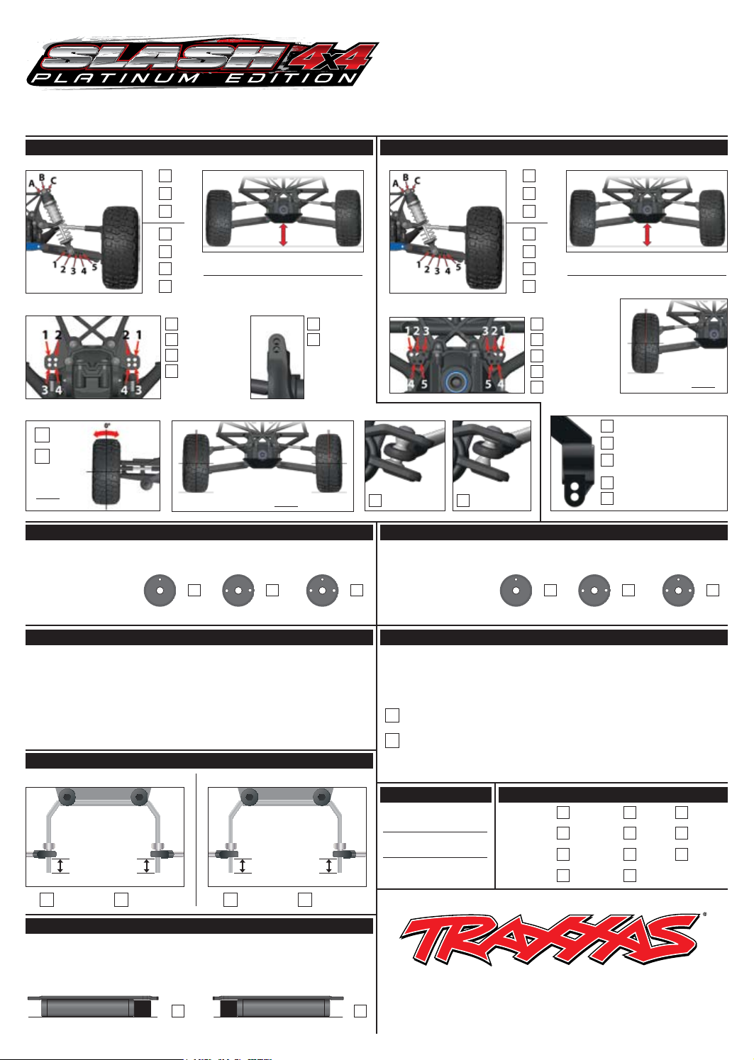
setup sheet
front suspension
TOP
A A
B B
X X
C C
BOTTOM
2 2
X X
3 3
Driveshafts level
Position 1
Position 2 Bottom
Position 3
Position 4
C-hub
Negative
toe angle
In
Out
0
°
4 4
5 5
X
camber angle bump steer
1.5
Driver: ______________________________________________
Date: ________________________ Air Temp: _____________
Event: ______________________________________________
Track/City: __________________________________________
Qual./Finish _________________________________________
shock positionshock position ride heightride height
camber link positioncamber link position
Top
X
°
Flat Down Flat Up
Factory Set Up
11-18-09
rear suspension
TOP
BOTTOM
Position 1
Position 2
Position 3
X
Position 4
Position 5
toe angle
X
Shafts slightly above level
camber angle
1.5
X
X
Negative
(Blue as labeled)4°
(Blue reversed)1°
(Black plastic)2.5°
Top
Bottom
°
front shocks
Springs (Color) ___________________ Preload _________mm
5
Oil __________ wt Oil __________ wt
Tire Type ________________
Tire Insert _______________
Wheel __________________
0
Stock Slash
______mm ______mm
Silver SilverBlack Black
X
Black dot
Piston: 1-hole Piston: 1-holePiston: 2-hole Piston: 2-holePiston: 3-hole Piston: 3-hole
wheels / tires
Front
S1 Compound S1 Compound
Stock Slash
sway bars
Front Rear
Tire Type ________________
Tire Insert _______________
Wheel __________________
Stock Slash
5
(Flush)
X
weight / balance
4
X
Rear
Stock Slash
0
Springs (Color) ___________________ Preload _________mm
40
Velineon 3500
Motor __________________
Battery _________________
Slipper
Center Differential _________ wt
X
Front Differential _________ wt Rear Differential _________ wt
Traxxas
Slash
4x4
rear shocks
Black dot
6
X
motor / drivetrain
Pinion ___________________
Spur ____________________
3s
VXL-
ESC __________________________________
13T
54T
100K
0
3
K
track conditionsbody type
Surface: Smooth Med. Rough
High Med. LowTraction:
Tight Med. OpenSize:
Yes NoWatered:
Greased
Weight Bias: Front _____% Rear _____% Weight: _______lbs.
Battery Placement:
RearFront
X
1100 KLEIN ROAD, PLANO TEXAS 75074
1-888-TRAXXAS, TRAXXAS.COM
091113
Page 7
Stiffer
Softer
Stiffer
Softer
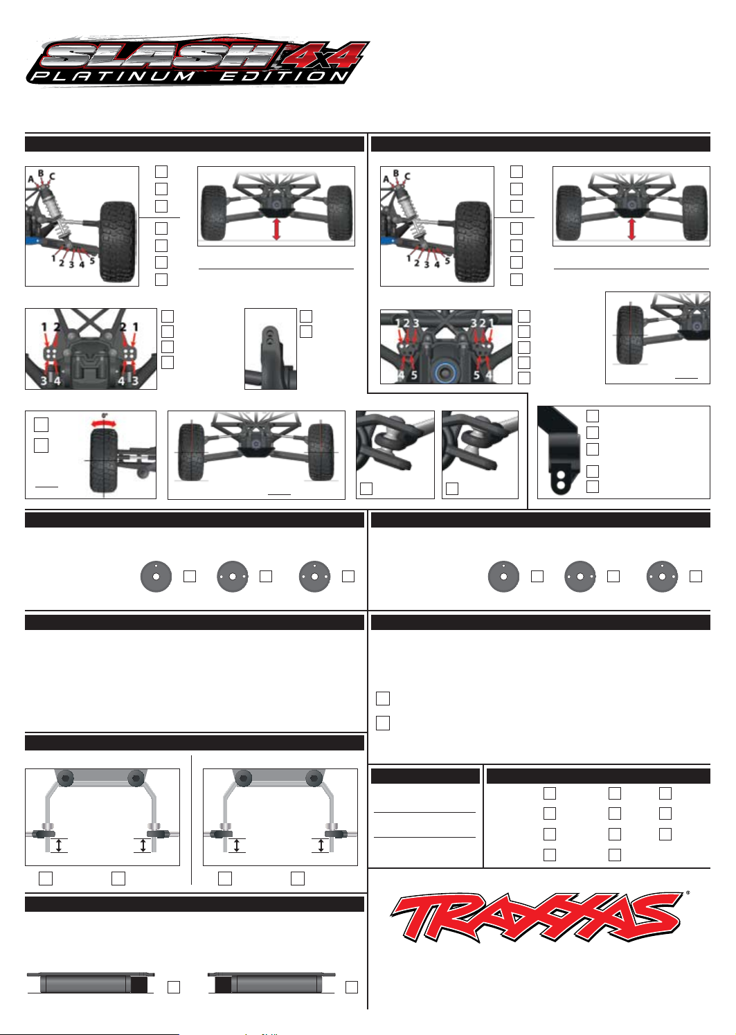
setup sheet
front suspension
TOP
A A
B B
C C
BOTTOM
2 2
3 3
4 4
5 5
C-hub
Negative
toe angle
In
Out
°
Position 1
Position 2 Bottom
Position 3
Position 4
camber angle bump steer
Driver: ______________________________________________
Date: ________________________ Air Temp: _____________
Event: ______________________________________________
Track/City: __________________________________________
Qual./Finish _________________________________________
rear suspension
shock positionshock position ride heightride height
camber link positioncamber link position
Top
°
Flat Down Flat Up
TOP
BOTTOM
Position 1
Position 2
Position 3
Position 4
Position 5
toe angle
camber angle
Negative
(Blue as labeled)4°
(Blue reversed)1°
(Black plastic)2.5°
Top
Bottom
°
front shocks
Springs (Color) ___________________ Preload _________mm
Oil __________ wt Oil __________ wt
Piston: 1-hole Piston: 1-holePiston: 2-hole Piston: 2-holePiston: 3-hole Piston: 3-hole
Springs (Color) ___________________ Preload _________mm
wheels / tires
Front
Tire Type ________________
Tire Insert _______________
Wheel __________________
Tire Type ________________
Tire Insert _______________
Wheel __________________
sway bars
Front Rear
______mm ______mm
Silver SilverBlack Black
Rear
Motor __________________
Battery _________________
Slipper
Center Differential _________ wt
Front Differential _________ wt Rear Differential _________ wt
weight / balance
rear shocks
motor / drivetrain
Pinion ___________________
Spur ____________________
ESC __________________________________
track conditionsbody type
Surface: Smooth Med. Rough
High Med. LowTraction:
Tight Med. OpenSize:
Yes NoWatered:
Weight Bias: Front _____% Rear _____% Weight: _______lbs.
Battery Placement:
RearFront
1100 KLEIN ROAD, PLANO TEXAS 75074
1-888-TRAXXAS, TRAXXAS.COM
091113
Page 8
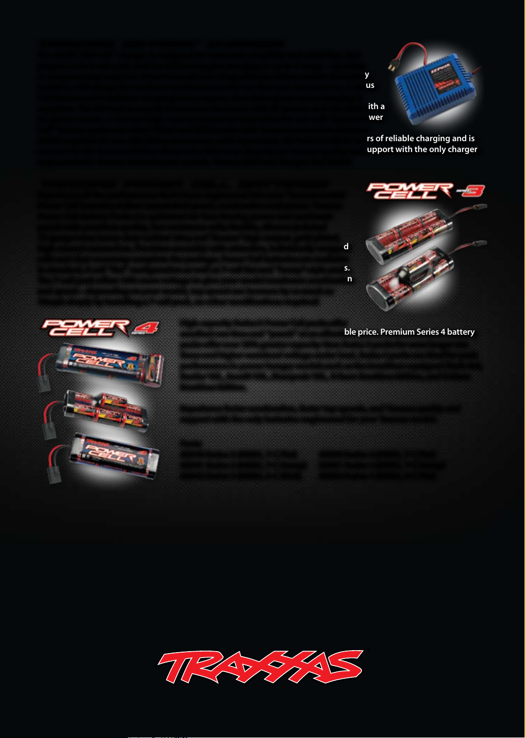
Traxxas EZ-Peak
The AC/DC EZ-Peak™ charger is designed for maximum simplicity and reliability. Just
plug in a 6 to 8-cell pack, and the EZ-Peak begins charging at up to 4-amps—no setup
or programming required. Patented peak-detecting software makes certain the battery
receives a full charge for maximum performance and run time you can count on. A status
LED ashes red to indicate charging is in progress, then turns green when charging is
complete. The EZ-Peak is equally at home on the bench with AC power, or in the eld with a
DC power source. A Traxxas High-Current Connector is installed for use with Traxxas Power
™
battery packs and other NiCad and NiMH packs with Traxxas connectors (Adapter
Cell
#3062 required for use with Molex connectors, sold separately). EZ-Peak is built for years of reliable charging and is
covered by the Traxxas Lifetime Electronics Warranty. Experience Traxxas quality and support with the only charger
engineered for Traxxas batteries and models. Traxxas EZ-Peak Charger Part #2930
Traxxas Power Cell Batteries
Experience all the performance that’s been engineered into your Traxxas model!
Power Cell batteries deliver unmatched speed, acceleration and power. Traxxas
Power Cell Battery Packs are optimized for free-owing power and maximum
punch with premium quality, low-resistance cells; exible, silicone-jacketed
12-gauge wire; heavy-duty welded tabs; and Traxxas’ high-output, gold plated,
high-current connectors. Precision assembly with attractive, individually wrapped
cells and clear overwrap complete the package. Power Cell batteries are available
in standard, 6-cell “at” conguration as well as 7-cell at and “hump”-style packs.
The 7-cell pack offers 15% more voltage to give your model maximum acceleration
and speed—depending on your model, top speed can increase by as much as
10mph simply by installing a 7-cell pack, no other modications required!
™
Charger
High-capacity Series 3 Power Cell packs offer
excellent run time and “punch” at an affordable price. Premium Series 4 battery
packs offer over 25% greater capacity than Series 3 packs for even longer run
times and higher sustained voltage under load. Series 4 packs are ideal for peak
performance in power-hungry models such as the brushless-equipped Slash 4x4,
Rustler VXL, Bandit VXL, Stampede VXL, E-Revo Brushless Edition, and E-Maxx
Brushless Edition.
Experience faster acceleration, faster top speeds, and Traxxas quality and
support with the only batteries engineered for your Traxxas model.
091118 KC1279-R00
Parts:
#2940 Series 3 (NiMH, 7-C Flat)
#2941 Series 3 (NiMH, 7-C Hump)
#2942 Series 3 (NiMH, 6-C Stick)
#2950 Series 4 (NiMH, 7-C Flat)
#2951 Series 4 (NiMH, 7-C Hump)
#2952 Series 4 (NiMH, 6-C Flat)
1100 Klein Road, Plano Texas 75074
1-888-TRAXXAS
 Loading...