

Page 1
Traulsen & Co., Inc.
Quality Refrigeration
Quality Refrigeration
OWNER’S MANUAL
Instructions for the installation, operation,
and maintenance of all Compact Undercounter
and Prep Table Models:
UHT27 ULT27 UPT276 UPT488 UPT6012
UHT48 ULT48 UPT279 UPT4812 UPT6018
UHT60 ULT60 UPT4818 UPT6024
This Traulsen unit is built to our highest quality standards. We build our refrigerators, freezers and heated
cabinets this way as a matter of pride. This philosophy has made Traulsen the leader in commercial refrigeration since 1938. We thank you for your choice and confidence in Traulsen equipment and we know you
will receive many years of utility from this equipment.
All Traulsen units are placed on a permanent record file with the service department. In the event of any
future questions you may have, please refer to the model and serial number found on the name tag affixed
to the unit. Should you need service, however, call us on our toll free number, 800-825-8220 between 7:30
am and 4:30 pm CST, Monday thru Friday. It is our pleasure to help and assist you in every possible way.
INSTALLER
COMPLETE THE FOLLOWING INFORMATION PRIOR TO UNIT INSTALLATION
INITIAL START DATE: SERIAL NO.
MODEL TYPE:
COMPANY/INDIVIDUAL NAME:
INSTALLER:
FORM NUMBER TR35746 REV. 5/03 P/N 375-60179-00
Page 2
TABLE OF CONTENTS
I. THE SERIAL TAG Page 1
II. RECEIPT INSPECTION Page 2
III. INSTALLATION
a-Location Page 2
b-Packaging Page 2
c-Installing Legs or Casters Page 2/3
d-Installing Shelf Clips Page 3
e-Cord & Plug Page 3
f-Power Supply Page 3
g-Wiring Diagram Page 3
h-Clearance Page 3
i-Optional Utility Base Page 3/4
j-Optional Stacking Kit Page 5
k-Sandwich Prep Top Assembly Page 5
l-Installing The Stainless Steel Top Page 6
IV. OPERATION
a-Prestart Checks Page 6
b-Temperature Control Page 6
c-Defrost Control Page 6/7
d-Refrigerating Product Page 7
e-Pans & Divider Bars Page 7
V. CARE & MAINTENANCE
a-Cleaning The Exterior Page 7
b-Cleaning The Interior Page 7
c-Cleaning The Condenser Coil Page 7
d-Condensate Removal System Care Page 7
e-Cleaning The Interior Page 7
VI. MISC. OPERATIONS
a-Rehinging The Door Page 8
b-Preparing For Extended Shut Down Page 8
c-Adjusting The Door Page 8
d-Door Gasket Replacement Page 8
VII. OTHER
a-Service Information Page 9
b-Spare Parts Page 9
c-Warranty Registration Page 9
VIII. TROUBLESHOOTING GUIDE Page 10
IX. PARTS LIST Page 11
X. WARRANTY INFORMATION Page 13
XI. INDEX Page 14
MODEL NO SN NO
ML MAX OPERATING AMBEINT
VOLTS HZ PH
TOTAL
AMPS
COMMERCIAL REFRIGERATOR AND/OR FREEZER
LISTED
C
MADE IN USA
NSF
I. THE SERIAL TAG
The serial tag is a permanently affixed sticker on
which is recorded vital electrical and refrigeration data
about your Traulsen product, as well as the model
and serial number. This tag is located on the left
interior wall on all compact undercounter refrigerator, freezer and prep table models.
READING THE SERIAL TAG
• Serial = The permanent ID# of your Traulsen
• Model = The model # of your Traulsen
• Volts = Voltage
• Hz = Cycle
• PH = Phase
• Total Current = Maximum amp draw
• Minimum Circuit = Minimum circuit ampacity
• Lights = Light wattage
• Heaters = Heater amperage (Hot Food units only)
• Refrigerant = Refrigerant type used
• Design Pressure = High & low side operating
pressures and refrigerant charge
• Agency Labels = Designates agency listings
-1-
Page 3
II. RECEIPT INSPECTION
III. INSTALLATION (continued)
All Traulsen products are factory tested for performance and are free from defects when shipped. The
utmost care has been taken in crating this product to
protect against damage in transit. All interior fittings
have been carefully secured and the legs or casters
are boxed and strapped inside to prevent damage.
You should carefully inspect your Traulsen unit for
damage during delivery. If damage is detected, you
should save all the crating materials and make note
on the carrier's Bill Of Lading describing this. A freight
claim should be filed immediately. If damage is subsequently noted during or immediately after installation, contact the respective carrier and file a freight
claim. Under no condition may a damaged unit be returned to Traulsen & Co. without first obtaining written permission (return authorization).
III. INSTALLATION
III. a - LOCATION:
Select a proper location for your Traulsen unit, away
from extreme heat or cold. Condenser performance
is dependent on adequate ventilation for cooling
purposes. Adequate clearance MUST be provided
for the ventilator locations underneath. There are
no clearance requirements for sides, rear, or top.
III. c - INSTALLING LEGS OR CASTERS (cont'd):
the factory inside a cardboard box which is secured
inside the cabinet. Casters in lieu of legs are supplied
as an optional accessory for all compact undercounter
models. The casters are “stem” type, and do not require the use of any bolts. When ordered, casters
are shipped in a separate box.
WARNING: THE CABINET MUST BE BLOCKED AND
STABLE BEFORE INSTALLING LEGS OR CASTERS.
Raise up and block the cabinet a minimum of 7" from the
floor and thread the legs into the threaded holes on
the bottom of the cabinet (see figure 1).
Fig. 1
NOTE: Do not install the cabinet without legs, casters or front ventilated utility base.
III. b - PACKAGING:
All Traulsen units are shipped from the factory bolted
to a sturdy wooden pallet and packaged in a durable
cardboard container. The carton is attached to the
wooden skid with the use of large staples. These
should first be removed to avoid scratching the unit
when lifting off the crate.
To remove the wooden pallet, first if at all possible, we
suggest that the cabinet remain bolted to the pallet
during all transportation to the point of final installation. The bolts can then be removed with a 5/8” socket
wrench by tipping or otherwise raising the unit to allow access to them. Avoid laying the unit on its front,
side or back for removal of the pallet.
NOTE: Traulsen does not recommend laying the unit
down on its front, side or back. However, if you must
please be certain to allow the unit to remain in an upright position afterwards for 24 hours before plugging
it in so that the compressor oils and refrigerant may
settle.
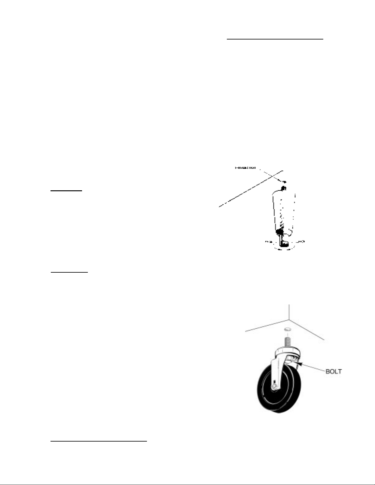
III. c - INSTALLING LEGS OR CASTERS:
6” high legs are supplied standard for all Traulsen
compact undercounter units. These are shipped from
Thread optional casters into the threaded holes on
the bottom of the cabinet in the same way (se e f igu re 2).
Casters with brake should be installed at the front.
Fig. 2
Level the cabinet using a level or pan of water in the
bottom of the cabinet. On units with legs, turn the
adjustable feet in or out to level the cabinet side-to-side
and front-to-back. Units with casters should be placed
on level floors.
-2-
Page 4
III. INSTALLATION (continued)
III. c - INSTALLING LEGS OR CASTERS (cont'd):
Please note that Traulsen units are not designed to
be moved while on legs. If the unit requires moving,
a pallet jack or forklift should be used to prevent
damage.
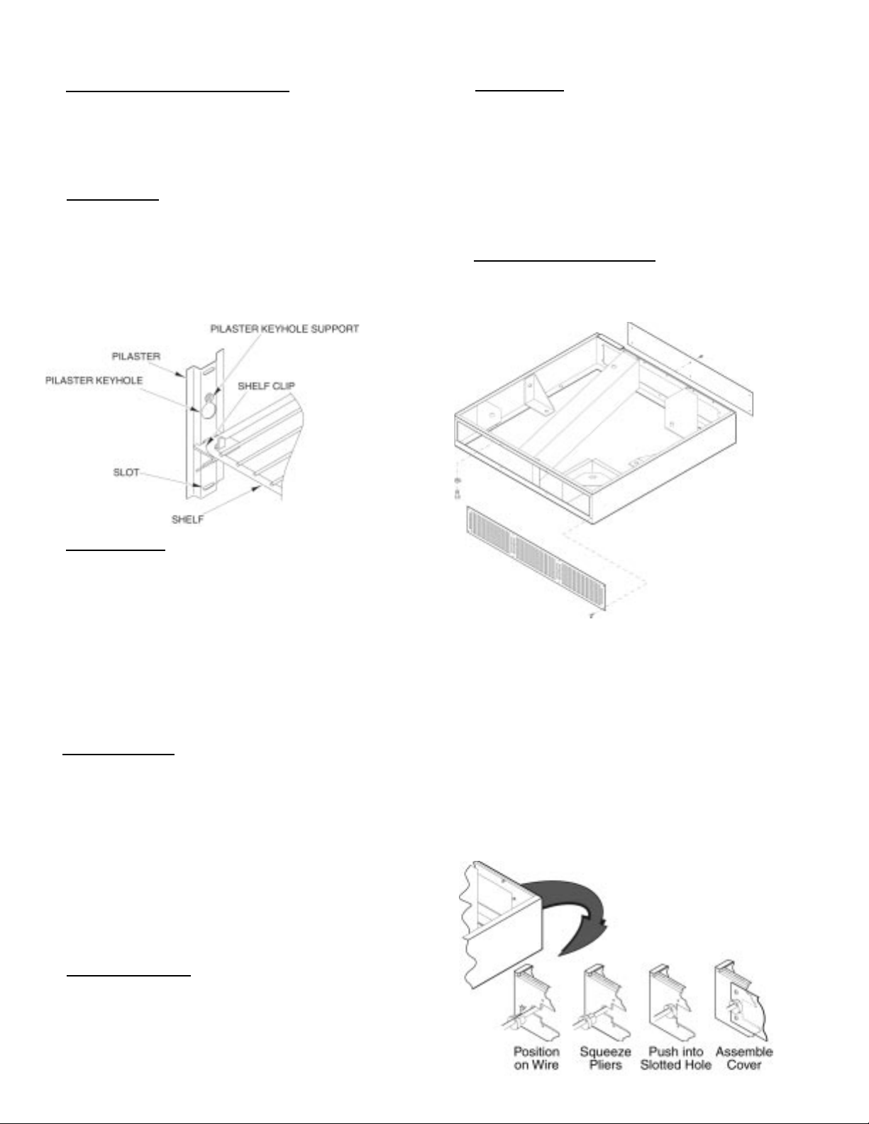
III. d - SHELF CLIPS:
Shelves and shelf clips are shipped with the unit.
For each shelf, insert four (4) shelf clips into the
pilaster slots at the same height (Fig. 3). The shelf
clips have a small projection on top which holds the
shelf in position and prevents it from slipping forwards.
After installing shelf clips on pilasters, place shelves
on clips.
Fig. 3
III. h - CLEARANCE:
It is important for the proper operation and longevity
of your Traulsen unit that it have adequate provisions
underneath for air supply to the compressor. There
are no clearance requirements for the sides, rear or
top.
NOTE: Do not install the cabinet without legs, casters
or a front ventilated utility base.
III. i - OPTIONAL UTILITY BASE:
An optional utility base is available, in lieu of legs
or casters, for models UHT27, ULT27, UPT276 &
UPT279 only. To install this, follow the directions
below see (figure 4):
III. e -
CORD & PLUG:
All UHT, ULT & UPT models are supplied with a cord &
plug attached. It is shipped coiled at the bottom of
the cabinet, secured by a nylon strip. For your safety
and protection, all units supplied with a cord and plug
include a special three-prong grounding plug on the
service cord. Select only a dedicated electrical outlet
with grounding plug for power source. NOTE: Do not
under any circumstances, cut or remove the round
grounding prong from the plug, or use an extension
cord.
III. f - POWER SUPPLY:
The supply voltage should be checked prior to connection to be certain that proper voltage for the cabinet wiring is available (refer to the serial tag to determine correct unit voltage). Make connections in accordance with local electrical codes. Use qualified
electricians.
Use of a separate, dedicated circuit is required. Size
wiring to handle indicated load and provide necessary
overcurrent protector in circuit (see amperage requirements on the unit’s serial tag).
Fig. 4
1. Place utility base in final installed location.
NOTE: The front of the utility base must be
oriented towards the front. Fastener locations
are provided for anchoring utility base to floor,
if desired; fasteners are not provided.
2. Place unit on top of utility base so holes
underneath are aligned. The plug cord must be
routed from the bottom right rear corner of the
unit through a slotted hole in the utility base.
Assemble the strain relief (provided) around the
electric cord and route it through the slotted
hole in the utility base.
Fig. 5
III. g - WIRING DIAGRAM:
Refer to the wiring diagram for any service work performed on the unit. Should you require one, please
contact Traulsen Service at (800) 825-8220, and provide the model and serial number of the unit involved.
-3-
Page 5
III. INSTALLATION (continued)
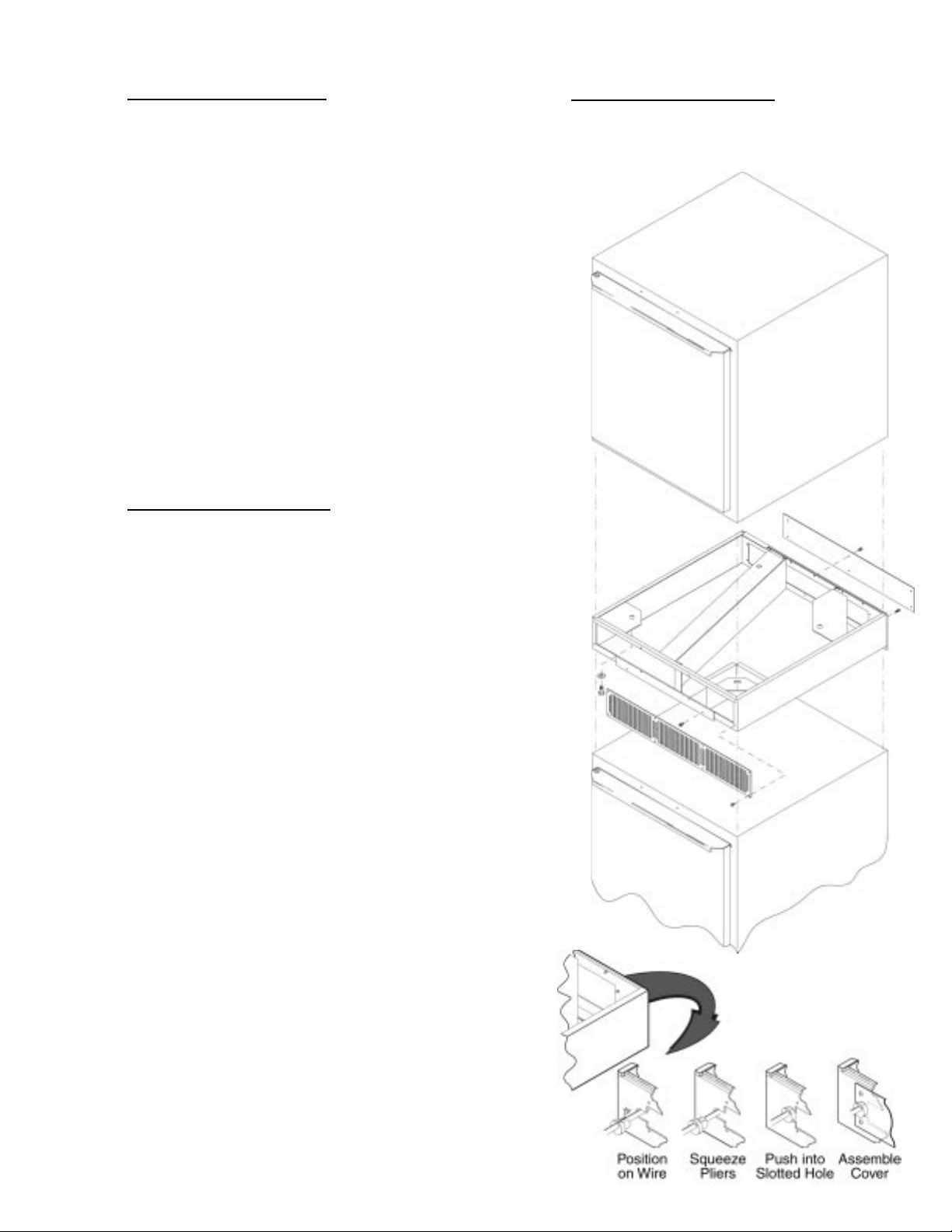
III. i - OPTIONAL UTILITY BASE (cont'd):
3. Assemble four 1/2 –13 bolts and lockwashers
through holes in utility base and into threaded
holes in bottom of unit where legs or casters
would be installed.
4. Place rear cover on back of utility base so D-slot
captures the groove of the strain relief. Attach
rear cover with six 8 – 18 self-tapping screws. If
floor receptacle is provided underneath utility
base for unit to plug into, strain relief will not be
used and rear cover should be installed up-sidedown so D-slot is covered.
5. Install front grill on front of stacking base with
eight 8 – 18 self-tapping screws.
If your unit comes with a utility base, we recommend
securing the base to the floor. Place the unit in its
final installed position, then apply a bead of NSF
approved silicone sealant around the bottom.
III. j - OPTIONAL STACKING KIT:
Models UHT27 and ULT27 only have the option of
a stacking kit, in which no more than two (2) units
can be stacked one on top of the other.
III. j - OPTIONAL STACKING KIT (cont'd):
8. Install front grill on front of stacking base with
eight 8 – 18 self-tapping screws.
1. Install legs, casters or utility base on bottom unit
following instructions elsewhere in this manual.
Place bottom unit near final installed location
leaving access to rear for further assembly.
2. Place stacking base on top of bottom unit. NOTE:
The front of the stacking base must be oriented
towards the front.
3. Assemble two 1/4 – 20 x 5/8" screws through front
mounting flange of stacking base into the
threaded holes in the front of the top edge of the
bottom unit. Assemble five 10 – 16 x 1/2" screws
through rear flange of the stacking base into the
upper rear of bottom unit.
4. Place upper unit on top of stacking base so holes
underneath are aligned.
5. Assemble four 1/2 – 13 bolts and lockwashers
through holes in stacking base into threaded
holes in bottom of upper unit where legs or
casters would be installed if unit were to sit
directly on the floor.
6. The plug cord must be routed from the bottom
right rear corner of the upper unit through a
slotted hole in the stacking base. Assemble the
strain relief (provided) around the electric cord
and route it through the slotted hole in the
stacking base.
Fig. 6
Fig. 6
7. Place rear cover on back of stacking base so the
D-slot captures the groove of the strain relief.
Attach rear cover with six 8 – 18 self-tapping
screws.
-4-
Page 6

III. INSTALLATION (continued)
III. k - SANDWICH PREP TOP ASSEMBLY:
On sandwich prep tables (see figure 8), the top
shelf, cutting board, and cover may require assembly
at the site.
1. Place the shelf on top of the rear of the unit.
Secure by screwing 4 threaded pins through base of
shelf and top of unit (see figure 9).
2. Install cutting board support. Secure with 2
threaded pins and 2 bolts per flange(see figure 9)
(wider units may be equipped with an additional
third pin in the center).
3. Assemble cutting board to cutting board support
(pins holding cutting board support fit through holes
in cutting board when properly aligned, see figure 9).
4. To install cover, flex cover so side pins fit in holes
at lower front corners of shelf (see figure 9). Cover
pivots up to open.
Fig. 8
CUTTING BOARD
SHELF
PINS (4)
Fig. 9
PINS (2)
CUTTING BOARD SUPPORT
FLANGE (1 OR 2)
BOLTS (2 @ FLANGE)
COVER
PINS (2)
-5-
Page 7

III. INSTALLATION (continued)
IV. OPERATION
III. l - INSTALLING THE STAINLESS STEEL TOP:
All 27", 48" and 60" wide compact undercounter
models can be supplied with an optional stainless
steel top. This must be installed on-site, to do so
please follow the directions below (see figure 10):
IV. a - PRESTART CHECKS:
The compressor must float freely before connecting
to electrical power. The compressor motor is
provided with rubber vibration isolator mounts (no
springs). No bolts need to be loosened. Check all
exposed refrigeration lines to make sure they are not
dented or kinked. Check for tubing shifts due to
shipping that would cause operating noise, wear, or
leaks. Check that condenser fan rotates freely.
The refrigeration system should be checked for
proper operation before product is stored in the
cabinet.
IV. b - TEMPERATURE CONTROL:
The temperature is set at the factory but local
conditions may necessitate slight adjustment.
The temperature control shown in figure 11 is located
on the right side of the evaporator housing. To
adjust, turn the adjustment screw with a screwdriver
a small amount at a time; turning clockwise lowers
the temperature. An " OFF" position is fully
counterclockwise and interrupts power to the
compressor and condenser fan only, not the entire
refrigerator.
Fig. 10
1. Peel off backing and install foam tape (provided)
around entire perimeter of the top of the unit.
2. A flange is assembled underneath at the front of
the countertop. This flange has two screw holes.
Screw the two 1/4 – 20 x 5/8" screws (provided)
through the holes in this front flange into the threaded
holes in the front of the top edge of the unit.
3. Using the five 10 – 16 x 1/2" screws provided,
screw the bottom of the rear cover plate to the upper
rear of the cabinet.
4. If the optional polyethylene cutting board top is
provided, there are four threaded pins which screw
into the four threaded holes in the worktop. The four
holes in the polyethylene cutting board top fit around
the heads of the four pins.
Colder
▼
Screw
Fig. 11
Thermostat - All
Current Models
O
N
F
R
Temperature
Adjustment
T
⇐
IV. c - DEFROST CONTROL:
Frozen food storage cabinets are equipped with a
defrost timer (figure 12) that provides a 20-minute
defrost cycle every 6 hours (four defrost cycles per
day).
Clockwise
Rotation
▼
Only
Defrost
Time
Control
Models ULT27, ULT48 & ULT60 Only
This control can be adjusted to set when the next
defrost cycle will start. To adjust the defrost time
control, use a coin on the outside slot in the rim of
the timer and turn clockwise until the compressor
turns off. Continue turning coin clockwise until the
Fig. 12
Defrost Timer
-6-
Page 8

IV. OPERATION
V. CARE AND MAINTENANCE:
IV. c compressor restarts. The next defrost cycle will
start in about 5 hours 40 minutes. On models
ULT27, ULT48 and ULT60, the defrost time control is
located on the right side of the evaporator housing,
behind the temperature control adjustment screw.
On earlier models ULT48 and ULT60, the defrost
time control was accessed through a small round
opening on the outside rear of the unit.
IV. d - REFRIGERATING PRODUCT:
A Thermometer (figure 13) is provided inside all
UHT, ULT & UPT models. Allow the cabinet to reach
normal operating temperature before loading.
UHT, ULT & UPT Series will satisfactorily refrigerate
an assorted load of food items. Allow space between
articles to permit free air circulation. Do not overload
at any one time with warm food products and expect
immediate results. A certain amount of time is
required to remove heat from items before operating
temperatures can be attained. The system is
designed for storage of refrigerated or frozen
product.
Opening the door will increase the temperature in
the cabinet and will require a certain amount of time
to recover. Also, after peak service periods or after
warm product is loaded, the refrigerator will require
a certain amount of time for the temperature to
return to the normal operating range.
IV. e Sandwich Prep models are provided with 1/6 size
plastic pans and metal divider bars. When 18 onesixth size pans are ordered, four standard and one
wide pan divider / supports are provided to achieve
appropriate pan separation. When 24 one-sixth size
pans are ordered, six standard and one wide pan
divider bars are provided to achieve appropriate
pan separation. All other arrangements use all
standard width pan divider bars.
DEFROST CONTROL (CONT'D):
°F °C
Fig. 13
PANS & DIVIDER BARS:
V. a - CLEANING THE EXTERIOR:
Exterior stainless steel should be cleaned with warm
water, mild soap and a soft cloth. Apply with a dampened cloth and wipe in the direction of the metal grain.
Avoid the use of strong detergents and gritty, abrasive cleaners as they may tend to mar and scratch the
surface. Do NOT use cleansers containing chlorine,
this may promote corrosion of the stainless steel.
Care should also be taken to avoid splashing the unit
with water, containing chlorinated cleansers, when
mopping the floor around the unit.
For stubborn odor spills, use baking soda and water
(mixed to a 1 TBSP baking soda to 1 pint water ratio).
V. b - CLEANING THE INTERIOR:
For cleaning the interior, the use of baking soda as
described in section “V. a” is recommended. Use on
breaker strips as well as door gaskets. All interior fittings are removable without tools to facilitate cleaning.
V. c - CLEANING THE CONDENSER COIL:
Check the condenser coil periodically. The operating
environment will affect the required frequency of
cleaning. Air must be able to freely circulate through
the condenser. This surface must be kept free of dirt
and grease for proper system operation. Remove
the lower rear panel on the rear of the equipment
cabinet. Carefully clean dirt and lint from the
condenser coil using a vacuum cleaner or soft brush;
do not use a wire brush. Replace the lower rear
panel. Reconnect electrical power supply.
V. d - CONDENSATE REMOVAL SYSTEM CARE:
The evaporator coil, condensate loop and
condensate pan, when needed, can all be flushed
with fresh water by a qualified service technician.
This should be part of any routine maintenance
program and can prolong the life of the equipment.
Condensate removal is provided by evaporation at the
lower rear portion of the equipment cabinet and
does not need a drain. Periodic cleaning of the
condensate removal box may be needed. To access
the condensate removal box, remove the lower panel
at the rear of the equipment cabinet. Clean the
condensate removal box by wiping it out with a clean
damp cloth, using care with the condensate loop
inside. Replace the lower rear panel. Reconnect
electrical power supply.
WARNING: DISCONNECT ELECTRICAL POWER
SUPPLY BEFORE CLEANING ANY PARTS OF THE
UNIT.
-7-
Page 9

VI. MISC. OPERATIONS
VI. a - REHINGING THE DOOR:
The door(s) on all UHT, ULT & UPT models can be easily rehinged in the field. To begin, open the door to its
maximum position. Support the non-hinged end of
the door so minimum movement occurs when the bolts
from the lower hinge plate are removed. Remove the
lower hinge plate and then the door from the top hinge
bracket. The hinge plate pin and plastic bushing will
remain in the top hinge plate (see figure 14).
Lower RH/
Upper LH
Hinge Plate
Fig. 14
Top Hinge Assembly
Door
Brass
Bushing
Lay the door down on a padded flat surface while being careful not to allow the lower hinge plate and
mechanism stem to slide out the bottom of the door.
NOTE: The lower hinge plate is under spring tension
(see figure 15). Grasp the lower hinge plate. While
keeping a firm grip on the plate, carefully slide it out
the bottom of the door just far enough to allow the
plate to rotate a full 360°. Unwind the tension of the
spring by carefully allowing the hinge plate to rotate a
full 360° several times.
Door
Spacer
Bushing
Hinge
Mechanism
Stem
Fig. 15
Bottom Hinge Assembly
Lower LH/Upper
RH Hinge Plate
Internal Tooth
Lock Washer
Screw
Slide the hinge plate and hinge mechanism stem out
the bottom of the door.
NOTE: Remove the brass bushing from the bottom of
the door only if spring replacement is necessary. Both
the spring and bushing will need to be new parts.
NOTE: When installing, make sure the lower hinge
plate and hinge mechanism stem are rotated no more
than six (6) full turns while applying tension to the
spring.
Center
Door In
Opening
-8-
VI. a - REHINGING THE DOOR (cont'd):
To reinstall the door, position the lower hinge plate
into the position of being open 90° to the cabinet.
Place the top hinge plate pin in the hole in the top of
the door and support the other end of the door for
minimal movement.
Start the bolts in the lower hinge plate and tighten the
bolts enough to hold the door in place. Remove the
block from under the end of the door. Adjust the door
as outlined in section VI. c.
VI. b - PREPARING FOR EXTENDED SHUT DOWN:
If the refrigerator is not to be used for an extended
period of time, disconnect the electrical power
supply and open the doors. As soon as the cabinet
has warmed up to room temperature, wipe out the
interior. Leave the doors open and check again to
make sure that no moisture has collected on any
parts. To restart refrigerator, follow instructions
under PRESTART CHECKS and OPERATION.
VI. c - ADJUSTING THE DOOR:
Occasionally the door(s) may require alignment
adjustment. To do so, first open the door and
loosen the hinge plate screws enough to move the
hinges if desired, but the door is held in place.
Center the door in the opening. Next level the top
hinge plate and tighten the screws. Finally, level
the lower hinge plate and tighten the screws (see
figure 16).
○○○○○○○
Loosen
Hinge Plates
○○○○○○○
○○○○○○○○○○
Fig. 16
VI. d - DOOR GASKET(S) REPLACEMENT:
Remove the old gasket by pulling it out from the
gasket retainer. Next, install the four corners of the
new gasket by pushing straight in on the gasket
until it is hooked behind the gasket retainer. Be
careful not to stretch the gasket as it will not return
to its original length. Starting at the center of one
edge, push the door gasket straight in until it is
hooked behind the gasket retainer. Proceeding
from this point out to the corners, continue pushing
the door gasket straight into the gasket retainer.
proceed doing the same to each of the remaining
edges until the gasket is completely installed.
Page 10

VII. OTHER
VII. a Before calling for service, please check the following:
If after checking the above items and the unit is still
not operating properly, please contact an authorized
Traulsen service agent. A complete list of authorized
service agents was provided along with your Traulsen
unit. If you cannot locate this, you may also obtain
the name of a service agent from the Tech Service page
of our website: www.traulsen.com.
If service is not satisfactory, please contact our inhouse service department at:
SERVICE INFORMATION:
Is the electrical cord plugged in?
Is the fuse OK or circuit breaker on?
Is the power switch “ON”?
Traulsen & Co., Inc.
4401 Blue Mound Road
Fort Worth, TX 76106
(800) 825-8220
Traulsen & Co., Inc. reserves the right to change specifications or discontinue models without notice.
VII. b Spare or replacement parts may be obtained through
a parts supplier or one of our authorized service
agents. A complete list of authorized service agents
accompanies this manual and is also posted on our
company's official website @ www.traulsen.com.
VII. c - WARRANTY REGISTRATION:
For your convenience, the warranties on your new
Traulsen unit may be registered with us by one of two
methods. Completing the enclosed warranty card
(shipped with the unit), or by filling out the on-line
warranty registration form located on the Technical
Service page of our website (www.traulsen.com).
SPARE PARTS:
-9-
Page 11

VIII. TROUBLESHOOTING GUIDE
FIND YOUR PROBLEM HERE REMEDY
1. Condensing unit fails to start. a. Check if cord & plug has been disconnected.
b. Check thermostat temperature setting.
2. Condensing unit operates for a. Are doors closing properly?
prolonged periods or continuously. b. Dirty condenser or filter. Clean properly.
c. Evaporator coil iced. Needs to defrost.
d. Shortage of refrigerant, call service.
3. Food compartment is too warm. a. Check door(s) and gasket(s) for proper seal
b. Perhaps a large quantity of warm food has
recently been added or the door was kept
open for a long period of time, in both
cases, allow adequate time for the cabinet
to recover its normal operating temperature.
c. Thermostat setting too high, readjust
per instructions on page 6.
d. Check that condensing coil is clean.
4. Food compartment is too cold. a. Perhaps a large quantity of very cold or frozen
food has recently been added. Allow adequate
time for the cabinet to recover its normal operating
temperature.
b. Adjust the thermostat to a warmer
setting, see page 6.
5. Condensation on the exterior surface. a. Check door alignment and gaskets for proper seal.
b. Condensation on the exterior surface of the
unit is perfectly normal during periods of
high humidity.
6. Compressor hums but does not start. a. Call for service.
-10-
Page 12

IX. PARTS LIST
PART NAME PART # DESCRIPTION
Back, Finished SER-60310-00 Optional Stainless Steel Finished Back For 27" Wide Models Only
Casters, 6" High SER-60275-00 Optional Set of Four (4) 6" High Casters For All 27" Wide Models
Casters, 6"" High SER-60276-00 Optional Set of Six (6) 6" High Casters For All 48" & 60" Wide Models
Casters, 3-1/2" High SER-60277-00 Optional Set of Four (4) 3-1/2" High Caster For All 27" Models
Casters, 4" High SER-60308-00 Optional Set of Four (4) 4" High Caster For All 27" Models
Hinge Plate SER-60248-00 Replacement Hinge Plate (upper left hand/lower right hand) For All Models
Hinge Plate SER-60249-00 Replacement Hinge Plate (upper right hand/lower left hand) For All Models
Shelf, 27" Models SER-60270-00 Additional or Replacement Shelf For 27" Wide Models
Shelf, Upper SER-60273-00 Additional or Replacement Upper Shelf For 48" Wide Models
Shelf, Lower SER-60274-00 Additional or Replacement Lower Shelf For 48" Wide Models
Shelf, Upper SER-60272-00 Additional or Replacement Upper Shelf For 60" Wide Models
Shelf, Lower SER-60271-00 Additional or Replacement Lower Shelf For 60" Wide Models
Shelf Clip SER-60269-00 Additional or Replacement Shelf Clip For All Models (four required per shelf)
Stacking Kit SER-60311-00 Optional Stacking Kit For 27" Wide UHT & ULT Models Only
Thermometer SER-60268-00 Replacement Thermometer For All Models
Top, 27" Models SER-60278-00 Optional Backsplash Top For 27" Wide Compact Refrigerator & Freezer Models
Top, 48" Models SER-60279-00 Optional Backsplash Top For 48" Wide Compact Refrigerator & Freezer Models
Top, 60" Models SER-60280-00 Optional Backsplash Top For 60" Wide Compact Refrigerator & Freezer Models
Utility Base, 6" High SER-60309-00 Optional 6" High Utility Base For 27" Wide Models Only
-11-
Page 13

X. WARRANTY INFORMATION
STANDARD DOMESTIC WARRANTY
TRAULSEN & CO., INC. warrants new equipment to the original purchaser, when installed within the United
States against defective material and workmanship for one (1) year from the date of original installation.
Under this warranty, TRAULSEN & CO., INC. will repair or replace, at its option, including service and labor,
all parts found to be defective and subject to this warranty. The compressor part is warranted for an additional
four (4) years. During this period TRAULSEN & CO., INC. will supply replacement compressor(s) if deemed
defective, however, all installation, recharging and repair costs will remain the responsibility of the owner.
This warranty does not apply to damage resulting from fire, water, burglary, accident, abuse, misuse, transit,
acts of God, attempted repairs, improper installation by unauthorized persons, and will not apply to food loss.
THERE ARE NO ORAL, STATUTORY OR IMPLIED WARRANTIES APPLICABLE TO TRAULSEN, INCLUDING BUT NOT LIMITED TO, ANY IMPLIED WARRANTY OF MERCHANTABILITY OR FITNESS FOR ANY
PARTICULAR PURPOSE WHICH EXTEND BEYOND THE DESCRIPTION ON THE FACE HEREOF.
TRAULSEN SHALL HAVE NO OBLIGATION OR LIABILITY FOR CONSEQUENTIAL OR SPECIAL DAMAGES, GROWING OUT OF OR WITH RESPECT TO THE EQUIPMENT OR ITS SALE, OPERATION OR
USE, AND TRAULSEN NEITHER ASSUMES NOR AUTHORIZES ANYONE ELSE TO ASSUME FOR IT
ANY OBLIGATION OR LIABILITY IN CONNECTION WITH THE EQUIPMENT OR ITS SALE, OPERATION
OR USE OTHER THAN AS STATED HEREIN.
INTERNATIONAL COMMERCIAL WARRANTY
(for Canadian warranties see domestic US warranty)
TRAULSEN & CO., INC. warrants to the original purchaser the Refrigeration Equipment manufactured and
sold by it to be free from defects in material and workmanship under normal use and service for a period of
one (1) year from date of shipment. Under this warranty, TRAULSEN & CO., INC. will reimburse the pur-
chaser for the replacement of any part of said equipment (excluding dryers & refrigerant gas) which then
proves to be defective. This warranty is void if said equipment or any part thereof has been subject to misuse,
damage in transit, accident, negligence or alteration.
TRAULSEN’S standard warranty does not apply to Export Sales. Rather, for a period of one (1) year from
date of original installation not to exceed Fifteen (15) months from date of shipment from factory, TRAULSEN:
will replace, F.O.B. factory, any defective parts normally subject to warranty.
will not cover the cost of packing, freight or labor such costs being the sole responsibility of the dealer.
THIS WARRANTY IS IN LIEU OF ALL OTHER WARRANTIES EITHER EXPRESSED OR IMPLIED AND
CONSTITUTES TRAULSEN’S FULL OBLIGATION AND LIABILITY. WARRANTIES NOT AVAILABLE ON
REMOTE MODELS.
-12-
Page 14

XI. INDEX
A
B
C
Cleaning, The Exterior 7
Cleaning, The Interior 7
Casters 2, 3
Condensate Evaporator 7
Cord & Plug 3
Condenser Coil, Cleaning 7
Condenser, Performance 2
Clearance 2, 3
Condensate Loop 7
Cutting Board 5
D
Defrost Control 6
Divider Bars 7
E
Evaporator Coil 7
Extended Shutdown, Preparing For 8
F
G
H
Hinge 8
R
Rehinging The Door 8
Return Authorization 2
S
Sealant, Silicone 4
Serial Tag 1
Shelf Clips 3
Shelves 3
Stacking Kit, Installing 4
Stainless Steel Top, Installing 6
T
Thermostat 7
U
Utility Base 4
V
W
Warranty 9
Warranty, Registration 9
Wiring Diagram 3
X
Y
Z
I
J
K
L
Legs 2, 3
M
N
O
P
Pallet, Wooden 2
Pans, Plastic 7
Parts Department 8
Parts, Spare 8
Pilaster Slots 3
Power Supply 4
Prep Top, Assembly 5
-14-
 Loading...