

Page 1

StackMaster TR
Active Retiming Managed Hub
SMHB-TR-16
#7361.C
™
Page 2

CAUTION: RJ connectors are NOT INTENDED FOR
CONNECTION TO THE PUBLIC TELEPHONE NETWORK.
Failure to observe this caution could result in damage to the
public telephone network.
Compliance Information
UL Listed
C-UL Listed (Canada)
CISPR/EN55022 Class A
FCC Regulations
This equipment has been tested and found to comply with the limits for a class
A digital device, pursuant to part 15 of the FCC rules. These limits are
designed to provide reasonable protection against harmful interference when
the equipment is operated in a commercial environment. This equipment
generates, uses, and can radiate radio frequency energy and, if not installed
and used in accordance with the instruction manual, may cause harmful
interference to radio communications. Operation of this equipment in a
residential area is likely to cause harmful interference, in which case the user
will be required to correct the interference at the user’s own expense.
Canadian Regulations
This digital apparatus does not exceed the Class A limits for radio noise for
digital apparatus set out on the radio interference regulations of the Canadian
Department of Communications.
European Regulations
Warning
This is a Class A product. In a domestic environment this product may cause
radio interference in which case the user may be required to take adequate
measures.
Copyright Restrictions
© 1995, 1996 TRANSITION Networks Inc.
All rights reserved. No part of this work may be reproduced or used in any
form or by any means – graphic, electronic, or mechanical – without written
permission from TRANSITION Networks Inc.
Trademark Notice
All registered trademarks and trademarks are the property of their respective
owners.
Der Anschluss dieses Gerätes an ein öffentlickes
Telekommunikationsnetz in den EG-Mitgliedstaaten verstösst gegen die
jeweligen einzelstaatlichen Gesetze zur Anwendung der Richtlinie
91/263/EWG zur Angleichung der Rechtsvorschriften der
Mitgliedstaaten über Telekommunikationsendeinrichtungen
einschliesslich der gegenseitigen Anerkennung ihrer Konformität.
Page 3

Table of Contents
Preface . . . . . . . . . . . . . . . . . . . . . . . . . . . . . . . . . . . . . . . . . . . . . . . . . . . . iii
1. INTRODUCTION . . . . . . . . . . . . . . . . . . . . . . . . . . . . . . . . . . . . . . . . . . . . 1–1
2. SITE PLANNING . . . . . . . . . . . . . . . . . . . . . . . . . . . . . . . . . . . . . . . . . . . . . 2–1
2.1 Site Considerations. . . . . . . . . . . . . . . . . . . . . . . . . . . . . . . . . . . . . . . 2–1
2.2 Network Parameters Data Sheets . . . . . . . . . . . . . . . . . . . . . . . . . . . .2–2
TCP/IP Network Parameters Data Sheet . . . . . . . . . . . . . . . . . . . . 2-2
SNMP Network Parameters Data Sheet. . . . . . . . . . . . . . . . . . . . . 2-3
Serial Port Parameters Data Sheet. . . . . . . . . . . . . . . . . . . . . . . . . 2-4
3. INSTALLATION . . . . . . . . . . . . . . . . . . . . . . . . . . . . . . . . . . . . . . . . . . . . .3–1
3.1 Unpacking StackMaster™TR Equipment . . . . . . . . . . . . . . . . . . . . . . .3–1
3.2 Stacking Units in Rack or on Table . . . . . . . . . . . . . . . . . . . . . . . . . . .3–2
3.2.1 Standard 19-Inch Rack Installation . . . . . . . . . . . . . . . . . . . . . . .3–2
3.2.2 Table-Top Installation . . . . . . . . . . . . . . . . . . . . . . . . . . . . . . . .3–3
3.3 Cascading StackMaster™TR Units . . . . . . . . . . . . . . . . . . . . . . . . . . .3–4
3.4 Connecting StackMaster™TR to Token Ring Network . . . . . . . . . . . .3–5
3.5 Connecting Units to Power . . . . . . . . . . . . . . . . . . . . . . . . . . . . . . . . .3–6
3.6 Resetting StackMaster™TR Stack . . . . . . . . . . . . . . . . . . . . . . . . . . . .3–7
Managed Stack . . . . . . . . . . . . . . . . . . . . . . . . . . . . . . . . . . . . . . .3–7
Unmanaged Stack . . . . . . . . . . . . . . . . . . . . . . . . . . . . . . . . . . . .3–7
3.7 Optionally Configuring SNMP Management at Attached Terminal . .3–8
3.7.1 Connecting to ASCII Terminal . . . . . . . . . . . . . . . . . . . . . . . . . .3–8
3.7.2 Bringing Up Configuration Software . . . . . . . . . . . . . . . . . . . . .3–9
3.7.4 Setting Network and SNMP Parameters . . . . . . . . . . . . . . . . . .3–10
Network Parameters . . . . . . . . . . . . . . . . . . . . . . . . . . . . . . . . . .3–10
SNMP Parameters . . . . . . . . . . . . . . . . . . . . . . . . . . . . . . . . . . .3–11
3.7.3 Resetting the StackMaster™TR . . . . . . . . . . . . . . . . . . . . . . . . .3–12
4. OPERATION . . . . . . . . . . . . . . . . . . . . . . . . . . . . . . . . . . . . . . . . . . . . . . . .4–1
4.1 Power On/Power Off . . . . . . . . . . . . . . . . . . . . . . . . . . . . . . . . . . . . .4–1
5. MAINTENANCE . . . . . . . . . . . . . . . . . . . . . . . . . . . . . . . . . . . . . . . . . . . . .5–1
5.1 Fault Isolation . . . . . . . . . . . . . . . . . . . . . . . . . . . . . . . . . . . . . . . . . . .5–1
5.2 Recovery Procedures . . . . . . . . . . . . . . . . . . . . . . . . . . . . . . . . . . . . .5–4
Resetting the StackMaster™TR . . . . . . . . . . . . . . . . . . . . . . . . . . . . . .5-4
i
User’s Guide
Page 4

5.3 Replacement Procedures . . . . . . . . . . . . . . . . . . . . . . . . . . . . . . . . . .5–5
Replacing StackMasterTR Unit Fuses . . . . . . . . . . . . . . . . . . . . . . . . .5–5
5.4 StackMasterTR Field Upgrades . . . . . . . . . . . . . . . . . . . . . . . . . . . . . .5–6
Installing SNMP Management Board . . . . . . . . . . . . . . . . . . . . . . . . . .5–6
5.5 Software Upgrades . . . . . . . . . . . . . . . . . . . . . . . . . . . . . . . . . . . . . . .5–9
Software Upgrade at Attached ASCII Terminal . . . . . . . . . . . . . . . . . .5–9
Obtaining Updated StackMaster™TR Software . . . . . . . . . . . . . . .5–9
Connecting to ASCII Terminal . . . . . . . . . . . . . . . . . . . . . . . . . . .5–9
Resetting the StackMasterTR . . . . . . . . . . . . . . . . . . . . . . . . . . . .5–10
Transferring the File . . . . . . . . . . . . . . . . . . . . . . . . . . . . . . . . . .5–10
ii
StackMasterTR
Page 5

Preface
This guide is intended for the system or network administrator responsible
for installing, configuring, using, and maintaining a Transition Engineering
StackMaster™TR. A working knowledge of local area network (LAN) operations, including familiarity with communications protocols used on interconnected LANs, is assumed.
iii
User’s Guide
Page 6

Page 7

1. Introduction
The TRANSITION Networks 16-Port StackMaster™TR Active Retiming
Managed Hubs are designed for building SNMP managed token ring LANs
using twisted pair cable.
The StackMaster™TR Managed Hub:
• Complies with current IEEE 802.5 token ring standards to ensure
interoperability
• Supports external SNMP network management
• Provides sixteen RJ-45 lobe ports support both STP and UTP
• Provides active signal retiming and regeneration on a per port basis
maximizes lobe and RI/RO cable runs
• Supports Category 3, 4 or 5 UTP/STP and IBM Type 1 Cable
• Allows 4 or 16 Mbps operation
• Allows RI/RO connection to both “active hubs” and “passive hubs”
• Delivers fault-tolerant, automatic ring wrap capability at RI/RO
• Provides Zero Delay Lockout, automatic lockout of station configured
at wrong speed
• Installed as standalone or rackmount in a standard 19” rackmount
frame.
• Provides serial port connection for Out of Band management.
NOTE: The StackMaster™TR 16-Port Hub is designed to support an
Active Retime environment with HOT SWAP capability. An active hub
can be added or removed without bringing the network down.
USER’S GUIDE
1-1
16 Port StackMaster TR
TRANSITION
networks
Power
Reset
™
Active Retiming Managed Hub
Insert
P
P
4 Mbps
Ring In
16 Mbps
A
A
Normal
1 2 3 4 5 6 7 8 9 10 11 12 13 14 15 16
Ring Out
Lobe Ports
Expansion Card
Indicators
Status
Enable
OFF
1234
ON
5678
ZDL
Page 8
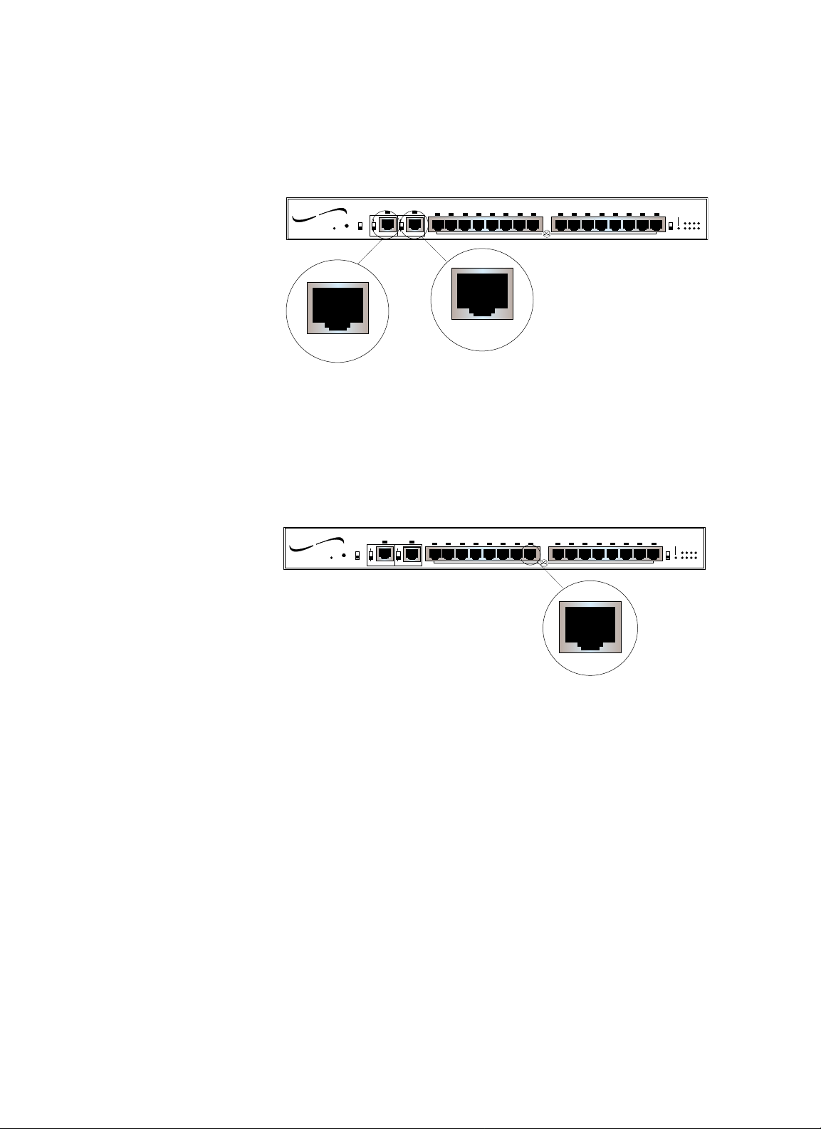
Connectors
Ring In/Ring Out Connector
An RJ-45 Ring In connector and an RJ-45 Ring Out connector are
provided at the front of the 16-Port StackMaster™TR Active Retiming
Managed Hub.
Lobe Connectors
Sixteen (16) RJ-45 lobe connectors are provided at the front of the 16-Port
StackMaster™TR Active Retiming Managed Hub.
1-2
StackMaster™TR
16 Port StackMaster TR
TRANSITION
networks
Power
Reset
™
Active Retiming Managed Hub
Insert
P
4 Mbps
16 Mbps
P
Ring Out
Ring In
A
A
Normal
1 2 3 4 5 6 7 8 9 10 11 12 13 14 15 16
Lobe Ports
R ing Out
Ring In
16 Port StackMaster TR
TRANSITION
networks
Power
Reset
™
Active Retiming Managed Hub
Insert
P
4 Mbps
16 Mbps
P
Ring In
A
A
Normal
1 2 3 4 5 6 7 8 9 10 11 12 13 14 15 16
Ring Out
Lobe Ports
Expansion Card
OFF
ON
ZDL
Expansion Card
Indicators
Status
Enable
OFF
1234
ON
5678
ZDL
Indicators
Status
Enable
1234
5678
Page 9

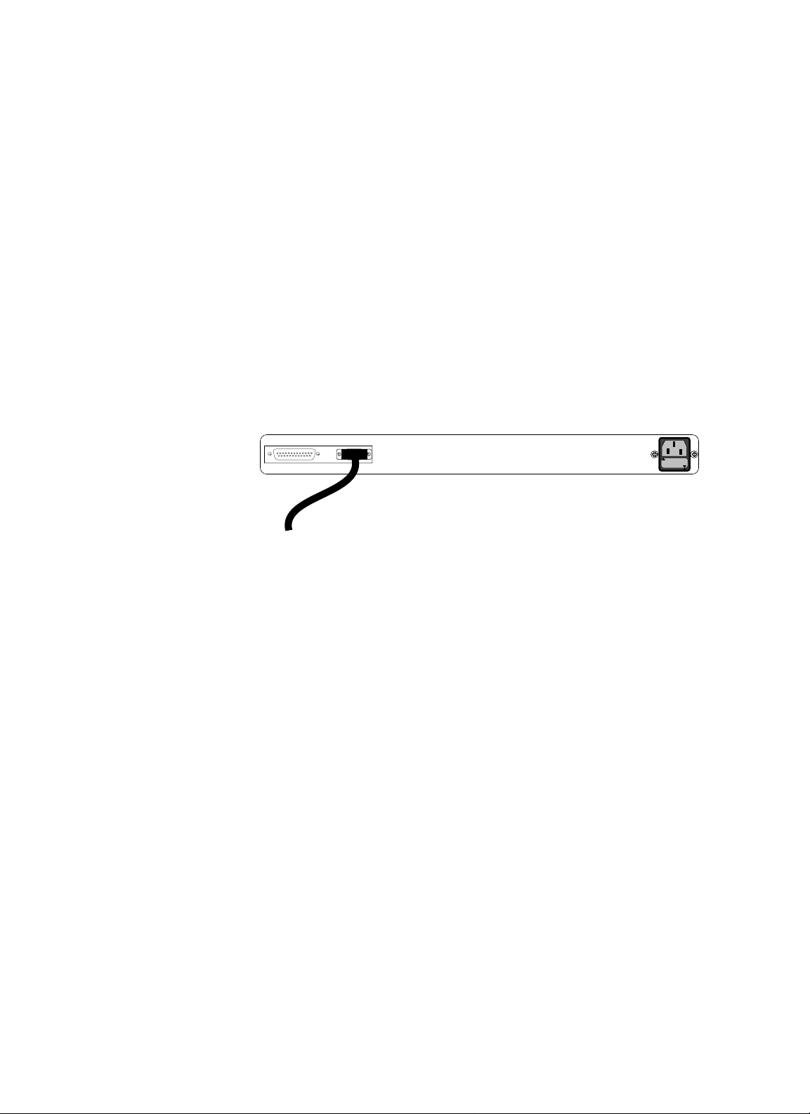
Connectors at Back
A serial port connector for SNMP management and maintenance, two (2)
Cascade (bus) connectors, and a power connector are provided at the
back of the StackMaster™TR 16-Port.
NOTE: The AUX connector is intended for future development.
11.. IINNTTRROODDUUCCTTIIOONN
USER’S GUIDE
1-3
Cascade (Bus) Connectors
Cascade Connectors
A
B
Serial AUX
TRANSITION
Serial
networks
Mpls, MN 55344
Model#: SMHB-TR-16
Caution : For continued protection against risk of fire, replace only
with same type and rating of fuse : 250V 2A.
Caution : Disconnect power before replacing fuse.
Achtung!: Zum anhaltenden Schutz vor Feurgefahr, Sicherung nur
mit einer gleichnamiger Stromstarke und Spannung
ersetzen: 250V, 2A
Achtung!: Stromleitung ausschalten bevor Sicherung ersetzen!
ATTENTION: Couper le courant avant de replacer le fusible.
Input Power: 100-240 V
50/60 Hz
0.5 A
Power Connector
2A, 250V
Page 10
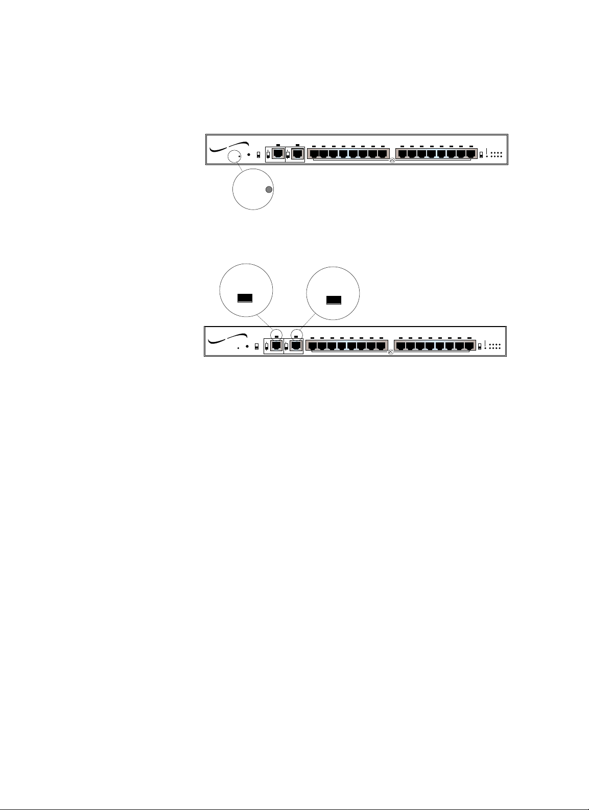
Indicators
Power LED
When the StackMaster™TR 16-Port Unit is powered, the Power indicator
is illuminated.
Insert/Normal LEDs
The Insert LED (above the Ring In port) is illuminated if the
StackMaster™TR 16-Port RI port is connected to the RO port of a hub.
NOTE: When the RI switch is in the passive position, the LED always is
ON, indicating that the RI port is configured in the passive mode.
The Normal LED (above the Ring Out port) is illuminated if the
StackMaster™TR 16-Port RO port is connected to the RI port of a hub
which is powered.
NOTE: When the RO switch is in the passive position, the LED always is
ON, indicating that the RO port is configured in the passive mode.
1-4
StackMaster™TR
16 Port StackMaster TR
TRANSITION
networks
Power
Reset
™
Active Retiming Managed Hub
4 Mbps
16 Mbps
Normal
Insert
P
P
Ring Out
Ring In
A
A
1 2 3 4 5 6 7 8 9 10 11 12 13 14 15 16
Lobe Ports
Expansion Card
Indicators
Status
Enable
OFF
1234
ON
5678
ZDL
Power
Insert
16 Port StackMaster TR
TRANSITION
networks
Power
Reset
™
Active Retiming Managed Hub
Insert
P
4 Mbps
16 Mbps
P
Ring In
A
A
Normal
Normal
1 2 3 4 5 6 7 8 9 10 11 12 13 14 15 16
Ring Out
Lobe Ports
Expansion Card
Indicators
Status
Enable
OFF
1234
ON
5678
ZDL
Page 11
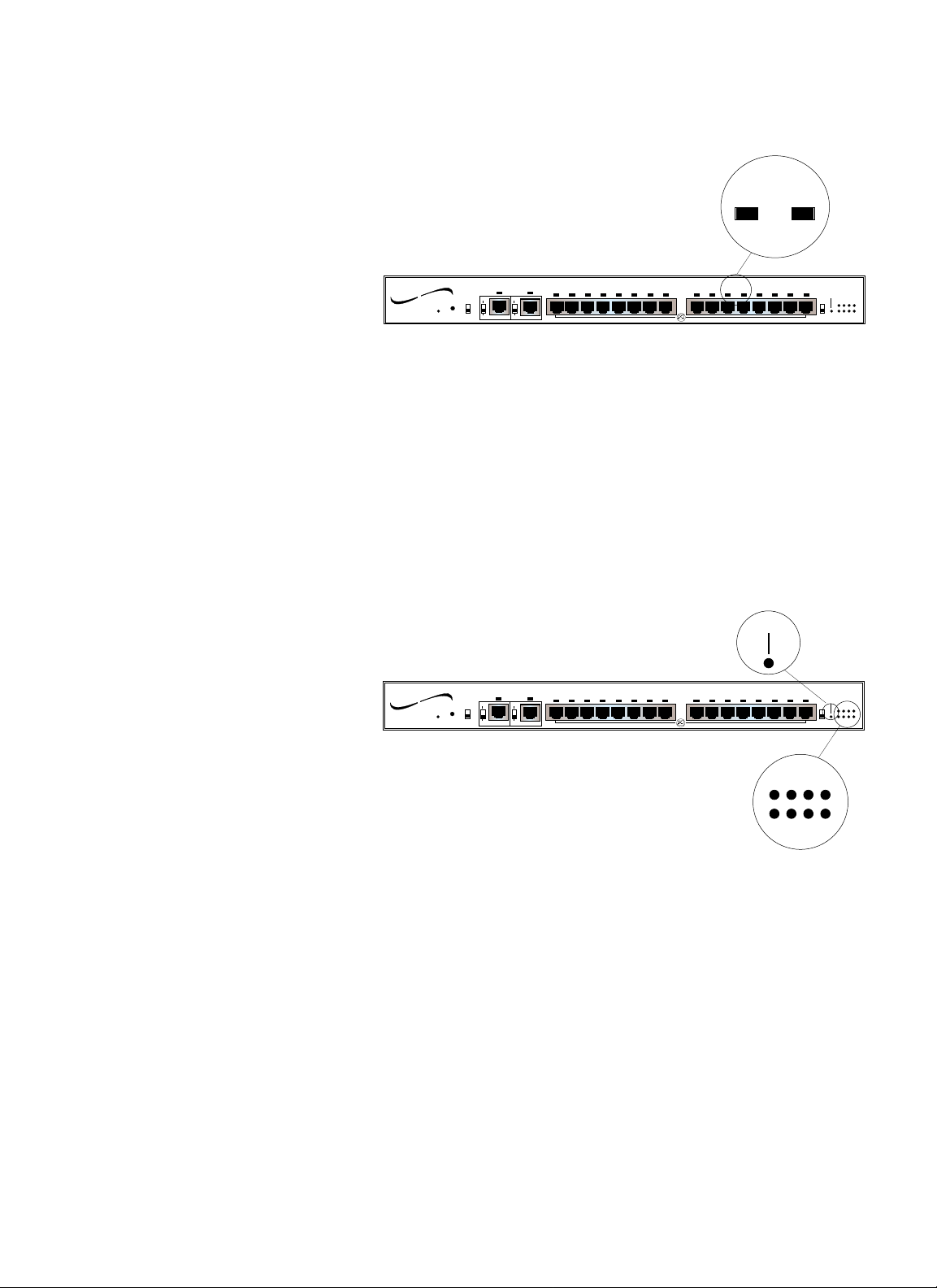
Port Status LEDs
Port Status LEDs above each of the sixteen (16) RJ-45 lobe port
connectors indicate insertion status for each of the sixteen connections:
green LED: good insertion
NOTE: Illuminated LEDs indicate insertion EXCEPT when a wrong speed
station is plugged into the hub; when a wrong speed station is plugged
into the hub, the iluminated LED indicates only that the connecting cable
is good.
Management Board LEDs
When the SNMP Management circuit board is installed and managing the
StackMaster™TR 16-Port Stack, the SNMP Management circuit board
indicators are active. The Enable indicator is illuminated when the SNMP
Management circuit board is installed. The eight Management Status
indicators cycle in a steady roll when the StackMaster™TR 16-Port Stack
is functioning normally.
11.. IINNTTRROODDUUCCTTIIOONN
USER’S GUIDE
1-5
11 12
Lobe Ports
Expansion Card
Indicators
Enable
OFF
1234
ON
5678
ZDL
Status
Power
™
networks
Reset
16 Port StackMaster TR
TRANSITION
Active Retiming Managed Hub
4 Mbps
16 Mbps
Normal
Insert
P
P
Ring Out
Ring In
A
A
1 2 3 4 5 6 7 8 9 10 11 12 13 14 15 16
Enable
16 Port StackMaster TR
TRANSITION
networks
Power
Reset
™
Active Retiming Managed Hub
Insert
P
4 Mbps
16 Mbps
P
Ring Out
Ring In
A
A
Normal
1 2 3 4 5 6 7 8 9 10 11 12 13 14 15 16
Lobe Ports
Expansion Card
Indicators
Enable
OFF
ON
ZDL
Status
1234
5678
Status
1
2
3
4
5
6
7
8
Page 12
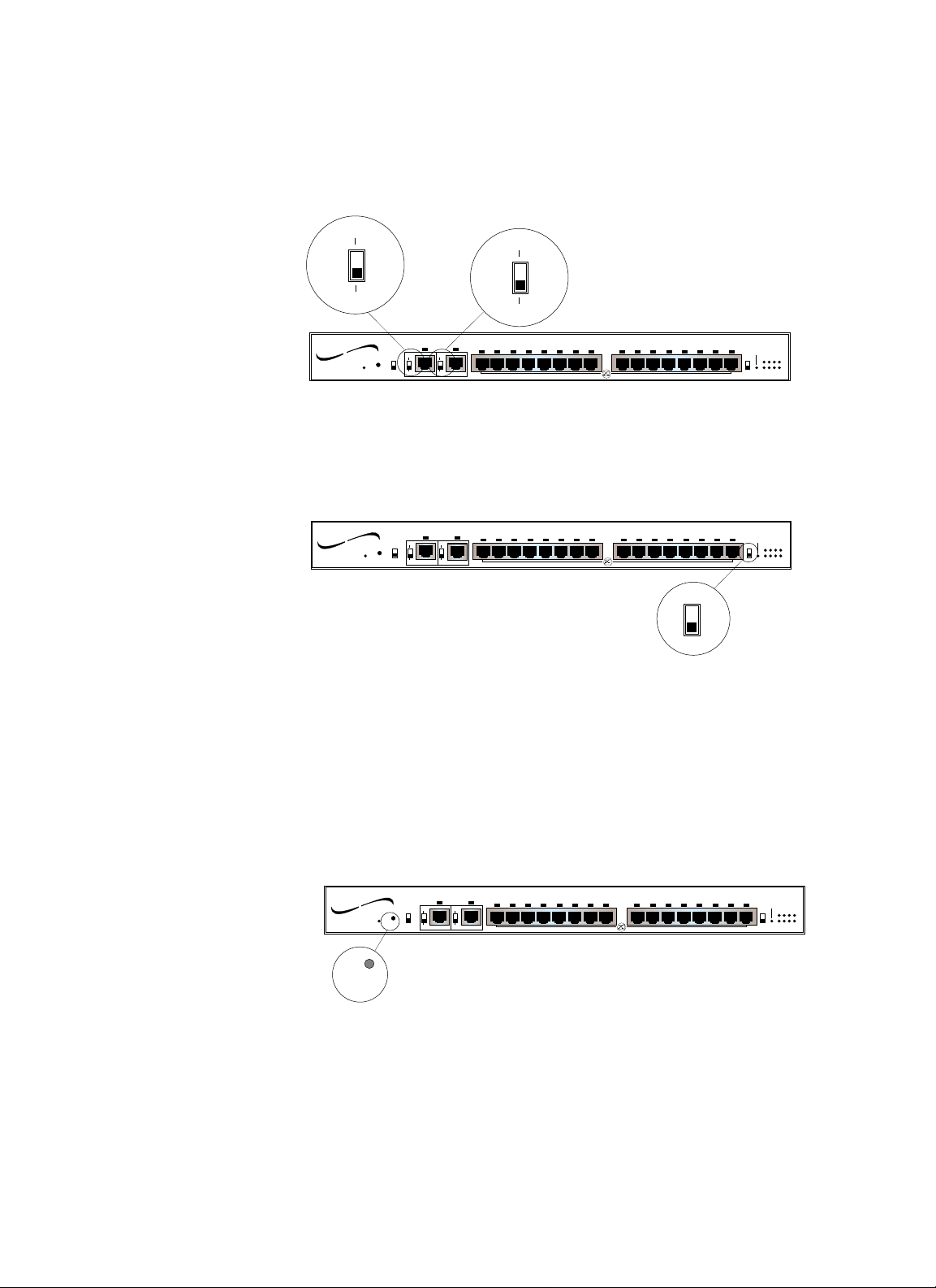
Switches
Active/Passive Switches
A(ctive) and P(assive) switches are provided for the Ring In port and for
the Ring Out port for connection to active ( “A” ) or to passive (“P”) hubs.
ZDL Switch
The ZDL Switch allows selection of automatic speed detection. NOTE:
The default position is ON. The OFF position is used for connecting non-
802.5 compliant equipment, such as the Hewlet Packard token ring tester.
NOTE: The StackMaster™TR 16-Port Hub must be reset when the ZDL
switch position is changed.
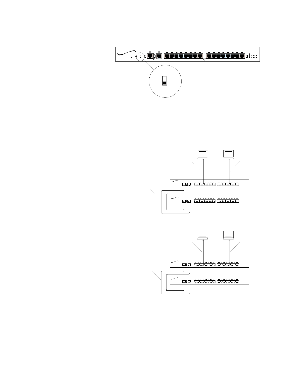
Reset Switch
A reset switch is located on the front of the StackMaster™TR 16-Port Hub.
The reset switch reinitializes the StackMaster™TR 16-Port Unit. If the
SNMP Management Board is installed in the StackMaster™TR 16-Port
Unit and the StackMaster™TR 16-Port Unit is installed at the top of a
Stack, the reset switch reinitializes the entire Stack.
1-6
StackMaster™TR
P
A
16 Port StackMaster TR
TRANSITION
networks
Power
Reset
™
Active Retiming Managed Hub
Insert
P
4 Mbps
16 Mbps
P
Ring Out
Ring In
A
A
Normal
P
A
1 2 3 4 5 6 7 8 9 10 11 12 13 14 15 16
Lobe Ports
Expansion Card
Indicators
Status
Enable
OFF
1234
ON
5678
ZDL
Lobe Ports
OFF
ON
Expansion Card
Indicators
Enable
OFF
ON
ZDL
ZDL
Status
1234
5678
Power
™
networks
Reset
Active Retiming Managed Hub
4 Mbps
16 Mbps
Normal
Insert
P
P
Ring Out
Ring In
A
A
1 2 3 4 5 6 7 8 9 10 11 12 13 14 15 16
16 Port StackMaster TR
TRANSITION
Lobe Ports
Expansion Card
Indicators
Enable
OFF
ON
ZDL
Status
1234
5678
Power
™
Active Retiming Managed Hub
4 Mbps
networks
Reset
16 Mbps
Normal
Insert
P
Ring In
A
1 2 3 4 5 6 7 8 9 10 11 12 13 14 15 16
P
Ring Out
A
16 Port StackMaster TR
TRANSITION
Reset
Page 13
4Mbps/16Mbps Switch
The 4Mbps/16Mbps Speed Selection Switch allows selection of data rate
(4Mbps or 16Mbps).
NOTE: The StackMaster™TR 16-Port Hub must be reset when the
4Mbps/16Mbps switch position is changed.
NOTE: Network speed affects maximum twisted pair cable distances.
11.. IINNTTRROODDUUCCTTIIOONN
USER’S GUIDE
1-7
Lobe Ports
Expansion Card
Indicators
Enable
OFF
ON
ZDL
Status
1234
5678
Power
™
networks
Reset
16 Port StackMaster TR
TRANSITION
Active Retiming Managed Hub
4 Mbps
16 Mbps
Normal
Insert
P
P
Ring Out
Ring In
A
A
1 2 3 4 5 6 7 8 9 10 11 12 13 14 15 16
4 Mbps
16 Mbps
Up to 400 m
with Category 5
STP
Up to 300 m
with Category 5
UTP
TRANSITION
networks
R OR I
4
16
TRANSITION
networks
R OR I
4
16
1 2 3 4 5 6 7 8 9 10 11 121314 15 16
1 2 3 4 5 6 7 8 9 10 11 121314 15 16
Up to 100 m
with Category 3
UTP
Up to 500 m
with Category 5
STP
Up to 500 m
with Category 5
UTP
TRANSITION
networks
R OR I
4
16
TRANSITION
networks
R OR I
4
16
Speed: 16 Mbps
1 2 3 4 5 6 7 8 9 10 11 121314 15 16
1 2 3 4 5 6 7 8 9 10 11 121314 15 16
Speed: 4 Mbps
Up to 300 m
with Category 3
UTP
Page 14

Page 15

2. Site Planning
Site planning for the StackMasterTR Stack requires consideration both of
site conditions and of token ring standards.
2.1 Site Considerations
The site for the StackMasterTR Token Ring Stack must provide the
following:
• AC power outlet for each StackMasterTR Unit
• Adequate ventilation
• Standard environmental conditions
• Isolation from electrical noise, including radio transmitters and
broadbank amplifiers, motors, high power electrical lines, or
fluorescent light fixtures
Additionally:
• The token ring cables should not run in the same conduit with power
line cables.
• Phone lines should be separated from data cables.
• Flat or “silver satin” wires should not be used.
2-1
USER’S GUIDE
Page 16

2.2 Network Parameters Data Sheets
NOTE: SNMP network management is optional.
The network parameter data sheets are intended to be a permanent record
of site-specific network parameter values that will be required for
configuring SNMP network management.
TCP/IP Network Parameters Data Sheet
CATEGORY StackMasterTR DEFAULT SITE ENTRY
IP address (ipaddr)
Management station
192.251.144.253
to which asynchronous
SNMP reports will be sent.
Format: xxx.xxx.xxx.xxx
EXAMPLE: 192.251.144.253
Subnet mask (submask)
Format: xxx.xxx.xxx.xxx 255.255.255.224
EXAMPLE: 255.255.255.224
Router (router)
Site-specific identifier. 0.0.0.0
Format: x.x.x.x
EXAMPLE:
0.0.0.0
Name (name)
Site-specific identifier NONE
Format: up to 256 characters
EXAMPLE:
NONE
Domain (domain)
Site-specific identifier.
NONE
Format: up to 256 characters
EXAMPLE:
NONE
Name of server
(nameserver)
Site-specific identifier 0.0.0.0
Format: x.x.x.x
EXAMPLE:
0.0.0.0
Table 2-1. TCP/IP Network Parameters Data Sheet
StackMaster™TR
2-2
Page 17

SNMP Network Parameters Data Sheet
CATEGORY StackMasterTR DEFAULT SITE ENTRY
(commwrite)
Security permission PRIVATE
Format: PRIVATE/PUBLIC
Authorization (auth)
Security identifier DISABLE
Format: DISABLE/ENABLE
System name (sysname)
Site-specific identifie -- usually. NONE
the host name.
Format: Up to 256 characters
Location (location)
Site-specific identifie -- usually. NONE
the host name.
Format: Up to 256 characters
(commread)
Security permission PUBLIC
Format: PRIVATE/PUBLIC
Location for SNMP
messages (trap) 0.0.0.0
Format: x.x.x.x
EXAMPLE:
0.0.0.0
(contact)
Site-specific identifier NONE
Format: Up to 256 characters
Table 2-2. SNMP Network Parameters Data Sheet
22.. SSIITTEE PPLLAANNNNIINNGG
2-3
USER’S GUIDE
Page 18

Serial Port Parameters Data Sheet
CATEGORY StackMasterTR DEFAULT SITE ENTRY
Transmission rate (bps)
Transmission speed, in bits 9600
per second
Format: 9600/
Name (stop bitse)
Serial protocol definition entry. 1
Format: NONE/1
(data bits)
Serial protocol definition entry. 8
Format: NONE/1
(parity)
Optional error checking entry NONE
Format: NONE/1
Table 2-3. Serial Port Parameters Data Sheet
StackMaster™TR
2-4
Page 19

3. Installation
To install the StackMaster™TR 16-Port Active Retiming Managed Hub::
• Unpack the StackMaster™TR Equipment
• Stack Units in Rack or on Table
• Cascade StackMaster™TR Units
• Connect StackMaster™TR to Network
• Connect Units to Power
• Optionally Configure SNMP Network Management
3.1 Unpacking StackMaster™TR 16-Port Equipment
Use the packing contents lists to verify the shipment:
Item Part Number
StackMaster Modular Chassis SMHB-TR-16
Special 6-inch DB-25 data cable 6005
Power Cord 3344 (or refer to Appendix D)
User’s Guide 7361
3-1
USER’S GUIDE
Page 20

3.2 Stacking Units in Rack or on Table
NOTE: StackMaster™TR 16-Port Units are shipped with attached brackets
for standard 19-inch rack installation and with attachable feet for table-top
installation.
3.2.1 Standard 19-Inch Rack Installation
CAUTION: The StackMaster™TR 16-Port Unit with the SNMP
Management Board must be installed at the top of the stack. Failure to
observe this caution will invalidate the SNMP network management.
NOTE: Rackmount screws and clip nuts are NOT provided with the
StackMaster™TR 16-Port Units.
To install the StackMaster™TR 16-Port Stack in a standard 19-inch rack:
1. Locate four (4) screws (and clip nuts, if necessary) for each
StackMaster™TR 16-Port Unit to be installed.
2. Locate the StackMaster™TR 16-Port Unit to be installed at the
bottom of the stack.
3. Carefully align the StackMaster™TR 16-Port Unit between the 19inch rack mounting rails at the lowest installation position.
4. Install two screws through right front bracket and two screws
through left front bracket, using clip nuts if necessary.
5. Carefully align the next StackMaster™TR 16-Port Unit above the
StackMaster™TR 16-Port Unit already installed.
6. Repeat steps 4 and 5 in reverse order until all StackMaster™TR
16-Port Units have been installed.
StackMasterTR
3-2
Page 21

3.2.2 Table-Top Installation
NOTE: StackMaster™TR 16-Port Units are shipped with a separate,
unattached set of adhesive-backed rubber feet.
CAUTION: The rubber feet MUST BE INSTALLED on the
StackMaster™TR 16-Port Unit if a StackMaster™TR 16-Port Unit is
installed on a table-top or other flat surface. Failure to observe this
caution could cause the StackMaster™TR 16-Port Unit to overheat and
could result in data transmission failure and/or equipment damage.
CAUTION: The StackMaster™TR 16-Port Unit with the SNMP
Management Board must be installed at the top of the stack. Failure to
observe this caution will invalidate the SNMP network management.
To install the StackMaster™TR 16-Port Stack on table or other flat surface:
1. Determine StackMaster™TR 16-Port Unit to be installed at
bottom of stack.
2. Carefully turn StackMaster™TR 16-Port Unit to side and install
four (4) rubber feet:
• Remove protective paper from adhesive surface of rubber
foot.
• Position rubber foot at bottom corner of Lanmaster Unit
• Secure rubber foot to StackMaster™TR 16-Port Unit.
• Repeat for remaining rubber feet.
3. Return StackMaster™TR 16-Port Unit to upright position.
4. Repeat step 2 for next StackMaster™TR 16-Port Unit to be
installed.
5. Carefully set StackMaster™TR 16-Port Unit on StackMaster™TR
16-Port Unit previously installed.
6. Continue steps 4 and 5 until all StackMaster™TR 16-Port Units
have been installed.
NOTE: The mounting brackets that come installed on the StackMaster™TR
16-Port Unit can be removed and saved for later use.
33.. IINNSSTTAALLLLAATTIIOONN
3-3
USER’S GUIDE
Page 22

3.3 Cascading StackMaster™TR Units
Cascading the StackMaster™TR cascades ONLY the SNMP management.
To cascade the StackMaster™TR units, use the RI/RO connections at the
front.
NOTE: Use only the special six-inch DB-25 (male-to-male) cables (PN
6005).The StackMaster™TR 16-Port DOES NOT require terminators.
To cascade a Stack in which the top unit has an SNMP management
board installed:
1. Connect six-inch DB-25 (male-to-male) cable to Cascade B of
StackMaster™TR 16-Port Unit.
2 Connect six-inch DB-25 (male-to-male) cable from
StackMaster™TR 16-Port Unit above to Cascade A of next
StackMaster™TR 16-Port Unit.
3. Connect six-inch DB-25 (male-to-male) cable from Cascade A to
Cascade B of same StackMaster™TR 16-Port Unit.
4. Continue steps 2 and 3 until all StackMaster™TR 16-Port Units
are connected.
StackMasterTR
3-4
Cascade A
Cascade B
220-240
110-120
Cascade A
Cascade B
Cascade A
Cascade B
110-120
110-120
220-240
220-240
Cascade A
Cascade B
220-240
110-120
Page 23

3.4 Connecting StackMaster™TR to Token Ring
Network
When NO connection to RI port: • ALWAYS set Ring In switch to Active position.
NOTE: The INSERT LED should remain OFF.
When NO connection to RO port: • ALWAYS set Ring Out switch to Active position.
NOTE: The NORMAL LED should remain OFF.
When adding passive hub to RI port: • Connect cable between StackMaster™TR RI and
RO of the passive hub
• Set Ring In switch to Passive position.
When adding passive hub to RO port: • Connect cable between StackMaster™TR RO and
RI of the passive hub
• Set Ring Out switch to Passive position.
When removing passive hub from RI port: • Set Ring In switch to Active position
• Disconnect cable between StackMaster™TR RI
and RO of the passive hub.
When removing passive hub from RO port: • Set “Ring Out” switch to Active position
• Disconnect cable between StackMaster™TR RO
and RI of the passive hub.
When interfacing to other manufacturers’ hub: The StackMaster™TR 16-Port is fully tested for
interoperatbility with other manufacturers’
concentrators that are compliant with 802.5
standards. Ensure that the RI/RO configuration of
the manufacturers’ concentrators functions with
the StackMaster™TR 16-Port.
33.. IINNSSTTAALLLLAATTIIOONN
3-5
USER’S GUIDE
Page 24

3.5 Connecting Units to Power
The StackMaster™TR 16-Port Stack is connected to power by connecting
each of the StackMaster™TR 16-Port Units to power.
NOTE: Connect StackMaster™TR 16-Port Units from bottom to top.
To connect the StackMaster™TR 16-Port Stack to power:
1. At StackMaster™TR 16-Port Unit back, locate the Unit power
receptacle and associated fuse.
NOTE: Fuse must be installed at correct setting for power source voltage
before connecting to AC outlet.
2. Verify that fuse is installed at correct setting for power source
voltage.
NOTE: The installed fuse rating is indicated by the reading at lower right
corner of fuse holder.
If not installed at correct setting for power source voltage:
• Carefully open fuse receptacle, using a small flat blade
screwdriver.
• Rotate fuse holder 180° to the correct rating orientation.
• Install fuse holder in correct rating orientation.
• Close fuse receptacle.
3. Plug unit end (female) of power cord into StackMaster™TR 16Port Unit power receptacle.
4. Plug outlet end (male) of power cord into correct voltage AC wall
socket.
5. At StackMaster™TR 16-Port Unit front, verify that POWER LED is
illuminated.
6. Repeat steps 1 through 5 until all StackMaster™TR 16-Port Units
have been powered.
StackMasterTR
3-6
110-120 Orientation 220-240 Orientation
220-240
110-120
Fuse Holder Fuse Holder
110-120
220-240
Page 25

3.6 Resetting StackMaster™TR 16-Port Stack
NOTE: The StackMaster™TR 16-Port Stack must be reset during
installation to initialize the internal software.
Managed Stack
• If the StackMaster™TR 16-Port Stack is managed, use a jewelers
screwdriver, paper clip, or other small device to depress the reset
switch inside the StackMaster™TR 16-Port Unit with SNMP
Management installed. The entire StackMaster™TR 16-Port Stack will
recycle and then resume normal operation.
Unmanaged Stack
• Reset the StackMaster™TR 16-Port units individually by using a
jewelers screwdriver, paper clip, or other small device to depress the
reset switch inside each StackMaster™TR 16-Port unit. The
StackMaster™TR 16-Port unit will recycle and then resume normal
operation. Other units in the StackMaster™TR 16-Port Stack will not
be affected.
33.. IINNSSTTAALLLLAATTIIOONN
3-7
USER’S GUIDE
Page 26
3.7 Optionally Configuring SNMP Network
Management at Attached Terminal
To set SNMP management parameters through an attached terminal:
• Connect the StackMaster™TR 16-Port to an ASCII terminal or terminal
emulator
• Bring up the StackMaster™TR 16-Port configuration software
• Reset the StackMaster™TR 16-Port
• Set Network and SNMP parameter values.
Connecting to ASCII Terminal
NOTE: The DB9 serial port on the StackMaster™TR 16-Port is a DTE
device. If the DB9 serial port cable will be attached directly between two
DTE devices, use a null modem cable. If the cable will be attached to a
9600 baud modem, use a straight through DB9 cable.
1. Locate the correct DB9 serial port cable with female DB9
connector.
2. Attach the DB9 serial port female cable connector to the male
DB9 serial port connector on the StackMaster™TR 16-Port .
3. Attach the other end of the DB9 serial port cable (directly or
indirectly through a modem) to an ASCII terminal or terminal
emulator.
NOTE: The StackMaster™TR 16-Port is shipped with standard serial port
parameter values:
baud 9600
stop bits 1
data bits 8
parity NONE
Using methods appropriate to the attached terminal, verify that the serial
port parameters of the attached terminal match the StackMaster™TR 16Port port parameter values. If necessary, modify the attached terminal port
parameter values.
StackMasterTR
3-8
Management Interface
To ASCII Terminal
Serial Port
110-120
220-240
Page 27

33.. IINNSSTTAALLLLAATTIIOONN
3-9
USER’S GUIDE
Bringing up Configuration Software.
NOTE: Refer to 1.6 for a detailed description of the StackMaster™TR 16Port Configuration Software Display available at the attached terminal.
To bring up the StackMaster™TR 16-Port configuration software, at the
attached terminal command line, enter:
^D
(“control D”)
The StackMaster™TR 16-Port Configuration Main Menu comes up.
At the StackMaster™TR 16-Port Configuration Main Menu, to select any of
the listed configuration menus, type and enter the name of the selected
menu:
MAIN> <selected menu>
AT ANY AND ALL CONFIGURATION MENUS:
To modify a parameter, use the command syntax:
ANY MENU> <parameter> = <value>
Alternatively, select a parameter available at a different menu by using the
command syntax:
ANY MENU > <any menu> <parameter> = <value>
To reference acceptable values for a parameter, use the help command
syntax:
ANY MENU> <parameter> = <?>
To bring up a reference list of line-editing commands, type and enter:
ANY MENU > keys
To exit, enter the command:
ANY MENU> quit
StackMaster™TR Configuration Main Menu
main serial
ip bootp
snmp misc
Select a parameter [main ==> root menu OR ? ==> help]
MAIN >
Page 28

StackMasterTR
3-10
Setting Network and SNMP Parameters
SNMP Network Management is configured by setting network and SNMP
parameter values.
Network Parameters
To set the Network parameter values at an attached terminal:
1. At the StackMaster™TR 16-Port Configuration Main Menu MAIN>
prompt, type and enter:
MAIN> ip
The StackMaster™TR 16-Port Network Parameters Menu comes up:
2. Referring to the Site Configuration Data Sheet, type and enter
modified configuration values in the format:
IP> <parameter> = <value>
3. Verify the modified configuration values by bringing up the same
menu:
IP> ip
The menu is redisplayed with the modified values.
4. Save the configuration values to non-volatile memory by typing
and entering:
IP> save
IP> restart
IP> quit
The StackMaster™TR 16-Port restarts and the parameter values entered are
written to non-volatile memory.
Network Parameters Menu
ipaddr = 192.251.144.253 name = NONE
submask = 255.255.255.0 domain = NONE
router = 0.0.0.0 nameserver= 0.0.0.0
Select a parameter [main ==> root menu OR ? ==> help]
IP>
Page 29

33.. IINNSSTTAALLLLAATTIIOONN
3-11
USER’S GUIDE
SNMP Parameters
To set the SNMP parameter values:
1. To access the SNMP Parameters Menu, at the Network
Parameters MAIN> prompt, type and enter:
MAIN> snmp
The StackMaster™TR 16-Port SNMP Parameters Menu comes up to
provide guidance in setting parameters for data to be used by the external
SNMP network management software:
2. Referring to the Site Configuration Data Sheet, type and enter
modified configuration values in the format:
SNMP> <parameter> = <value>
3. Verify the modified configuration values by bringing up the same
menu:
MENU> snmp
The menu is redisplayed with the modified values.
3. Save the configuration values by typing and entering the
following
SNMP> save
SNMP> restart
SNMP> quit
The StackMaster™TR 16-Port restarts and the parameter values entered
are written to non-volatile memory.
SNMP Parameters Menu
commwrite = PRIVATE commread = PUBLIC
auth = DISABLE trap = 0.0.0.0
sysname = NONE contact = NONE
location = NONE
Select a parameter [main ==> root menu OR ? ==> help]
SNMP >
Page 30

StackMasterTR
3-12
Resetting the StackMaster™TR 16-Port
NOTE: The StackMaster™TR 16-Port can be reset in any of the following
ways:.
• Disconnect power cord to StackMaster™TR 16-Port unit with installed
SNMP management board, then reconnect the power cord.
• Press the reset button on the StackMaster™TR 16-Port unit with
installed SNMP management board
• At the attached terminal or terminal emulation, type and enter:
ANY MENU> restart
ANY MENU> quit
At power on or reset, the Status LEDs cycle through diagnostic test patterns
as internal StackMaster™TR 16-Port software tests: Flash, serial port,
dynamic RAM, static RAM, dual port memory, and each of the Ethernet
ports.
After the diagnostic test patterns, for twenty seconds, the Status LEDs
display a pattern in which four LEDs remain illuminated while four LEDs
flash continuously. This pattern indicates that the StackMaster™TR 16-Port
software is waiting for an optional user interrupt.
Page 31

4. Operation
4.1 Power On/Power Off
The StackMaster™TR 16-Port Stack is powered ON when the power
cords are connected from all the StackMaster™TR 16-Port Units to AC
outlets.
NOTE: When powered, the POWER LED on each StackMaster™TR 16Port Unit should be illuminated.
The StackMaster™TR 16-Port Stack is powered OFF when the power
cords are disconnected from all the StackMaster™TR 16-Port Units or
from all the AC outlets.
4-1
USER’S GUIDE
Page 32

Page 33

5. Maintenance
Maintenance of the StackMaster™TR 16-Port Stack is required only when
a StackMaster™TR 16-Port unit fails. Recovery of a failed
StackMaster™TR 16-Port unit requires fault isolation, using methods
provided in this section, and corrective action. Corrective action is taken
by simple procedures described in this section or by contacting
TRANSITION Networks Technical Support.
5.1 Fault Isolation
Use Table 5-1 for troubleshooting the StackMaster™TR 16-Port Stack.
Table 5-1 presents a list of faults and probable causes, presented in the
order of increasing probability, with suggested remedial action.
To use Table 5-1, locate the problem in the FAULT column. In the
PROBABLE CAUSE box next to the fault, find one or more probable
cause(s) associated with the fault. Examine each probable cause in turn,
beginning at the top. When the probable cause is identifed, take the
associated corrective action in the CORRECTIVE ACTION column.
FAULT PROBABLE CAUSE CORRECTIVE ACTION
Unit POWER LED Disconnected Connect power cord.
not illuminated power cord.
Improperly For 110-120V use,
installed fuse. fuse should read 110-
120V in upright position;
for 210-240V use, fuse
should read 210-240V in
upright position.
Fuse failure. Replace fuse. (See 5.3.1.)
Power supply Contact Technical
failure. Support.
1-800-260-1312
USER’S GUIDE
5-1
Page 34

Insert RI LED The active hub’s Switch RO to “P”
not illuminated and RO port may be (passive) position.
RI connected to configured as
active hub RO port passive.
Normal RO LED The active hub’s Switch RI to “P”
not illuminated and RI port may be (passive) position.
RO connected to configured as
active hub RI port passive.
Lobe Port LED Cable failure Check cable assembly or
not illuminated (open/short). tester or swap cable with
known good cable.
Incorrect RJ45 cable See 3.5.2 for pin
installed. specifications
Invalid cable pin- See 3.5.2 for cable
outs. pin-outs
Workstation or Check NIC
server NIC failure. configuration/setup with
manufacturer.
Lobe port connector Contact TN Technical
failure. Support.
1-800-260-1312.
5-2
StackMaster™TR
Page 35

Unit “freezes”. RI, RO switches are Set unconnected port
in passive position switch to “A”(active)
but one port is not position.
connected.
ZDL disabled and Switch ZDL to ON
wrong speed station and reset hub.
tries to insert.
RI or RO cable Replace cable.
broken while in
“Passive” position.
Cannot manage Stack initialization Reset Stack (See 5.2
stack
Incorrect Replace cable.
management cable
used.
Table 5-1. Fault Isolation in the StackMaster™TR 16-Port Stack
55.. MMAAIINNTTEENNAANNCCEE
USER’S GUIDE
5-3
Page 36

5.2 Recovery Procedures
Recovery of a failed StackMaster™TR 16-Port Unit or Stack is
accomplished, often, by resetting the StackMaster™TR 16-Port Stack
Managed Stack
• If the StackMaster™TR 16-Port Stack is managed, use a jewelers
screwdriver, paper clip, or other small device to depress the reset
switch inside the StackMaster™TR 16-Port Unit with SNMP
Management installed. The entire StackMaster™TR 16-Port Stack will
recycle and then resume normal operation.
NOTE: Disconnecting power also will reset the StackMaster™TR 16-Port
Stack.
Unmanaged Stack
• Reset the StackMaster™TR 16-Port units individually by using a
jewelers screwdriver, paper clip, or other small device to depress the
reset switch inside each StackMaster™TR 16-Port unit. The
StackMaster™TR 16-Port unit will recycle and then resume normal
operation. Other units in the StackMaster™TR 16-Port Stack will not
be affected.
NOTE: Disconnecting power also will reset the StackMaster™TR 16-Port
Stack.
5-4
StackMaster™TR
Page 37

55.. MMAAIINNTTEENNAANNCCEE
USER’S GUIDE
5-5
5.3 Replacement Procedures
WARNING! StackMaster™TR 16-Port Units contain no user-serviceable
parts. With the exception of installation of the SNMP management
board, DO NOT, UNDER ANY CIRCUMSTANCES, open and attempt to
repair StackMaster™TR 16-Port equipment. Failure to observe this
warning could result in electrical shock and personal injury.
NOTE: Failure to observe the above warning will immediately void any
warranty.
Replacing StackMaster™TR 16-Port Unit Fuses
To replace a StackMaster™TR 16-Port Unit fuse:
1. Disconnect outlet end of power cord from AC wall socket.
2. Disconnect the power cord from the StackMaster™TR 16-Port
Unit power receptacle.
3. Carefully open fuse receptacle, using small flat blade
screwdriver.
CAUTION: Replace fuse only with same size and rating. Failure to
observe this caution could result in equipment damage.
NOTE: Installed fuse rating orientation is indicated as read in lower right
corner of fuse holder.
4. Install replacement fuse holder in correct rating orientation.
5. Close fuse receptacle.
6. Connect unit end (female) of power cord to StackMaster™TR
16-Port Unit power receptacle.
7. Connect outlet end (male) of the power cord to the AC wall
socket.
8. At StackMaster™TR 16-Port Unit front, verify that POWER
LED is illuminated.
110-120 Orientation 220-240 Orientation
220-240
110-120
Fuse Holder Fuse Holder
110-120
220-240
Page 38

5-6
StackMaster™TR
5.4 StackMaster™TR 16-Port Field Upgrades
StackMaster™TR 16-Port allows a field upgrade installation of an SNMP
Management Board
5.4.1 Installing SNMP Management Board
WARNING: DISCONNECT THE POWER CORD from
theStackMaster™TR 16-Port Unit before installing the SNMP
Management Board. Failure to observe this warning could result in
personal injury or death from electrical shock.
WARNING: AVOID CONTACT WITH POWER SUPPLY during Board
installation. Failure to observe this warning could result in personal
injury from electrical shock caused by capacitive discharge.
CAUTION: Wear a grounding device and observe electrostatic discharge
precautions when installing the SNMP Management board. Failure to
observe this caution could result in circuit board failure.
Tools: Medium Phillips screwdriver
Small slotted screw driver
3/16-inch nut driver
To install the SNMP Management board:
1. Place StackMaster™TR 16-Port Unit on table or other stable
surface.
2. Using Phillips screwdriver, remove four (4) screws that secure
the cover to the StackMaster™TR 16-Port Unit left side and
four (4) screws that secure the cover to the StackMaster™TR
16-Port Unit right side.
3. Using Phillips screwdriver, remove two (2) screws that secure
the cover to StackMaster™TR 16-Port Unit back.
4. Using 3/16-inch nut driver, remove four (4) hex nuts that
secure the cover to the Cascade Connectors and two (2) hex
nuts that secure the cover to the serial port connector.
Page 39

55.. MMAAIINNTTEENNAANNCCEE
USER’S GUIDE
5-7
NOTE: The internal fan is attached to the cover. Fan wires connect to the
attachedStackMaster™TR 16-Port circuit board.
5. Using necessary force, slide cover back to disengage from
chassis.
6. Without disconnecting fan wires, carefully lift the front of the
StackMaster™TR 16-Port Unit cover. Rotate the cover over
the StackMaster™TR 16-Port Unit until the cover rests
securely behind, and next to, the StackMaster™TR 16-Port
Unit.
7. Align the two snap-fit ends of the two SNMP Management
circuit board plastic spacers to the associated SNMP
Management circuit board holes.
8. Align the SNMP Management circuit board DIN connector
pins (male connector) to the StackMaster™TR 16-Port circuit
board DIN connector (female connector).
9. Apply downward pressure to the SNMP Management circuit
board until the SNMP Management circuit board DIN
connector is seated securely and the snap-fit connectors snap
into place.
Page 40

5.4.1 Installing SNMP Management Board
(continued)
10. Without crimping the fan wires, rotate the StackMaster™TR
16-Port Unit cover to rest on chassis.
11. Slide cover forward to engage cover against chassis
12. Replace the cover screws.
5-8
StackMaster™TR
Page 41

55.. MMAAIINNTTEENNAANNCCEE
USER’S GUIDE
5-9
5.5 Software Upgrades
NOTE: The management circuit board uses “flash ROM”, which allows
firmware upgrades to be received over a serial interface.
5.5.1 Software Upgrade at Attached ASCII Terminal
To upgrade the flash ROM:
• Obtain a copy of updated StackMaster™TR 16-Port software
• Establish a serial connection to an ASCII terminal or terminal
emulation.
• Reset the StackMaster™TR 16-Port Management Unit
• Transfer the file.
Obtaining Updated StackMaster™TR 16-Port Software
Updated software can be obtained through the Transition Networks
Bulletin Board Service at:
(612) 941-9304
through the Transition Networks Web site at:
www.transition.com
or by contacting Transition Networks.
Connecting to ASCII Terminal
NOTE: The DB9 serial port on the StackMaster™TR 16-Port is a DTE
device. If the DB9 serial port cable will be attached directly between two
DTE devices, use a null modem cable. If the cable will be attached to a
9600 baud modem, use a straight through DB9 cable.
1. Locate the correct DB9 serial port cable with female DB9
connector.
2. Attach the DB9 serial port female cable connector to the male
DB9 serial port connector on the StackMaster™TR 16-Port .
3. Attach the other end of the DB9 serial port cable (directly or
indirectly through a modem) to an ASCII terminal or terminal
emulator.
NOTE: The StackMaster™TR 16-Port is shipped with standard serial port
parameter values:
baud 9600
stop bits 1
data bits 8
parity NONE
Using methods appropriate to the attached terminal, verify that the serial
port parameters of the attached terminal match the StackMaster™TR 16Port port parameter values. If necessary, modify the attached terminal
port parameter values. THEN RESET THE STACKMASTER™TR.
Page 42

5-10
StackMaster™TR
Page 43

55.. MMAAIINNTTEENNAANNCCEE
USER’S GUIDE
5-11
Resetting the StackMaster™TR 16-Port
Reset the StackMaster™TR 16-Port in any of the following ways:.
• Disconnect power cord to SNMP Management Unit or to
StackMaster™TR 16-Port Unit with installed SNMP management
board, then reconnect the power cord.
• Press the reset button on the SNMP Management Unit or
StackMaster™TR 16-Port Unit with installed SNMP management
board.
• At the attached terminal or terminal emulation, type and enter:
ANY MENU > restart
ANY MENU > quit
At power on or reset, the Status LEDs cycle through diagnostic test
patterns as internal StackMaster™TR 16-Port software tests: Flash, serial
port, dynamic RAM, static RAM, dual port memory, and each of the
Ethernet ports.
After the diagnostic test patterns, for twenty seconds, the Status LEDs
display a pattern in which four LEDs remain illuminated while four LEDs
flash continuously. This pattern indicates that the StackMaster™TR 16-Port
software is waiting for an optional user interrupt.
Transferring the File
To transfer the file:
1. Determine the exact drive and path to the updated .BIN file.
NOTE: Step 2 must be completed during the twenty-second period that
the Status LEDs display the optional user interrupt pattern.
Ready to RECEIVE file using XMODEM/crc/binary/xon/xoff.
Initiate SEND from host . . .
Stop Sending
Page 44

Page 45

Appendix A. Technical Specifications
Network Standards
Ethernet IEEE 802.5
Interface Connector
One (1) Ring In, one (1) Ring Out, and sixteen (16) Lobe RJ-45 connectors are provided on the
front of the StackMaster™TR.
One (1) DB9 connector is provided on the back of the StackMaster™TR for Out-Of-Band
communication.
Universal Power Supply
Input Range: 85 to 265 VAC at 47 to 63 Hz. Rated at 40 watts maximum.
AC Input:
TE PN Requirement Location
3344 120 volts, 60 hertz USA/Canada/Mexico
3344 100 volts, 50-60 hertz Japan
3347 230 volts, 50 hertz Europe
3348 240 volts, 50 hertz Australia
3349 240 volts, 50 hertz United Kingdom
Operating Environment
Temperature: 32° to 122° F (0° to 50° C)
Humidity: 10% to 90% non-condensing
Altitude: 0 to 10,000 feet
Dimensions
Height 1.625” (4cm) Width 19” (48cm) Depth 8“ (20cm).
AAPPPPEENNDDIIXX
USER/S GUIDE
A-1
Page 46

Page 47

AAPPPPEENNDDIIXX
USER/S GUIDE
B-1
Appendix B. Cable Specifications
Twisted Pair Cable Specifications
Either shielded or unshielded twisted pair can be used. Category 5wire or better is recommended.
• Gauge. . . . . . . . . . . . . . . . . . 26 to 22 AWG
• Attenuation . . . . . . . . . . . . . Less than 11.5 dB @ 5-10 MHz
• Differential Characteristic . . 85 -110 Ω Impedance
@ 10 MHz
RJ-45 Pin Specifications
Null Modem Cable Specifications
The table below shows the pin assignments for the DB9 cable.
Function
Mnemonic
Carrier Detect CD
Receive Data RXD
Transmit Data TXD
Data Terminal Ready DTR
Signal Ground GND
Data Set Ready DSR
Request To Send RTS
Clear To Send CTS
Ring Indicator RI
Straight Through Cable at RJ-45 Plug
RJ-45 Male RJ-45 Male
3 . . . . . . . . . . . . . . . . . . . . . . 3
4 . . . . . . . . . . . . . . . . . . . . . . 4
5 . . . . . . . . . . . . . . . . . . . . . . 5
6 . . . . . . . . . . . . . . . . . . . . . . 6
The two active pairs in the token ring RJ-45
connector are pins 4 & 5 and pins 3 & 6. Use
only dedicated wire pairs (such as blue/white &
white/blue, orange/white & white/orange) for the
active pins.
Page 48

Page 49

Appendix C. Cable Distance
Cable Catagory Speed Max-Lobe Length* Max-RI\RO Length*
UTP 3 16Mbps 100 meters 150 meters
UTP 5 16Mbps 300 meters 300 meters
STP 5 16Mbps 400 meters 400 meters
UTP 3 4Mbps 300 meters 300 meters
UTP 5 4Mbps 500 meters 500 meters
STP 5 4Mbps 500 meters 500 meters
*Distances as tested with IBM Token Ring and SMC Token Elite Cards. Other cards guaranteed to
100 meters per 802.5 specification.
AAPPPPEENNDDIIXX
USER/S GUIDE
C-1
Page 50

Page 51

AAPPPPEENNDDIIXX
USER/S GUIDE
D-1
Appendix D. Approved European Power Cord Set
Embossed Alternative Wire
Harmonization Color Codes
Approval Organization Marking Blk Red Ylw
Belgium:Comite
Electrotechnique Beige (CEBEC) CEBEC-HAR 10 30 10
Verband Deutscher Elektrotechniker
(VDE)e, V., Prufstelle VDE-HAR 30 10 10
Technique de l’Electricite (UTE) UTE-HAR 30 30 10
Institute del Marchio Qualita IEMMEQU-HAR 10 30 50
British Approvals Service For
Electric Cables (BASEC-HAR) BASEC-HAR 10 10 30
N.V. tot Keuring van Electro-
technische Matarialien (KEMA) KEMA-KEUR-HAR 10 30 30
Svenska Elecktriska (SMEKO) SMEKO-HAR 10 10 50
Osterreichnischer Verband ful
Electrotechnik (OVE) OVE-HAR 30 10 50
Danmark Elektriske
Materielkontroll (DEMKO) DEMKO-HAR 30 10 30
Institute for Industrial Research
and Standards (IIRS) IRS-HAR 30 30 50
Norges Elektriske
Materielkontroll (NEMKO) NEMKO-HAR 10 10 70
National Standards Authority of
Ireland (NSAI) NSAI-HAR 30 30 50
Page 52

Page 53

AAPPPPEENNDDIIXX
USER/S GUIDE
E-1
Warranty Statement
A. Five Year Warranty
Transition Networks, Inc. (TN) warrants, for a period of five years, that TN products (with the
exception of power supplies and fans that TN warrants for two years) will be free from defects in
materials and workmanship, and will be in conformity with TN’s specifications.
TN’s warranty on products manufactured by or assembled for TN in accordance with a customer’s
specifications, is a five-year warranty that the goods conform to such specifications.
The warranty is invalidated if the goods have been subject to alterations, misuse, accident, Acts of
God (e.g., damage by floods, lightning strikes, Etc.), tampering, improper maintenance, improper
installation, or abuse. If the user is unsure about the proper means of installing or using the
equipment, contact TN’s free Technical Support or Network Design Services, which can be
reached by:
Telephone 1.800.LAN.WANS or 612.941.7600
Fax 612.941.2322
E-mail techsupport@transition.com
Internet http://www.transition.com
THE ABOVE WARRANTY IS EXCLUSIVE AND EXTENDS ONLY TO PRODUCTS ASSEMBLED BY
TRANSITION NETWORKS, INC. TO THE EXTENT PERMITTED BY LAW, TN DOES NOT MAKE
AND DISCLAIMS ALL OTHER WARRANTIES, EXCEPT TITLE, EXPRESSED OR IMPLIED,
INCLUDING, BUT NOT LIMITED TO, ANY WARRANTY OF DESCRIPTION, MERCHANTIBILITY,
FITNESS FOR A PARTICULAR PURPOSE OR NON-INFRINGEMENT, AND ANY WARRANTY
BASED UPON PRIOR WRITTEN OR ORAL REPRESENTATIONS REGARDING SUCH PRODUCTS
MADE BY TN, ITS EMPLOYEES, AGENTS, OR REPRESENTATIVES.
B. Limitations and Exclusions
If the customer believes any goods sold by TN are defective and within the warranty period, the
following general procedure will be followed:
1.Locate the serial number and delivery date of the item(s).
2.Notify TN within the warranty period.
3.TN will promptly issue a return authorization form for the goods.
4.Upon receiving the form, the customer will promptly return the item(s) at customers own
expense, shipped prepaid, to the distributor from which it was purchased, or directly to TN.
TN will only accept goods for return if the following conditions have been met:
1.A return form is obtained from TN.
2.The freight charges have been prepaid by the customer.
3.Goods are re-packed in their original packaging.
If under warranty TN shall, at its option, (1) repair the goods free of charge (2) replace the goods
free of charge, or (3) accept the return of the item(s) and credit the current price to the reseller
(within 90 days of purchase), or (4) if the goods are not under warranty, will repair the item(s) at a
minimum charge of USD $200 (two hundred U.S. dollars) per item.
THIS IS THE EXCLUSIVE REMEDY FOR ANY BREACH OF WARRANTY. IN NO EVENT SHALL
TRANSITION NETWORKS BE LIABLE FOR SPECIAL, INDIRECT, INCIDENTAL OR
CONSEQUENTIAL DAMAGES OF ANY KIND, WHETHER FOR BREACH OF ANY CONDITION
OF SALE, FOR NEGLIGENCE, ON THE BASIS OF STRICT LIABILITY, CONTRACT, OR
OTHERWISE AND IRRESPECTIVE OF WHETHER TN IS INFORMED BY CUSTOMER OF THE
POSSIBILITY OF SUCH DAMAGES IN ADVANCE OF THIS SALE.
Page 54

E-2
StackMaster™TR
The sole purpose of this remedy shall be provided the customer with the replacement or repair of
non-conforming goods in the manner described in this Warranty statement. This exclusive remedy
shall not be deemed to have failed of its essential purpose so long as TN is willing and able to
repair or replace the defective item(s) or refund the purchase price.
TN reserves the right to inspect products claimed to be defective under warranty either at the
customer’s location or at TN’s plant. TN assumes no liability for liability charges incidental to the
adjustment, service, repairing, removal or replacement of the product, or other costs, or the
expense of repairs made outside of its factory, except when made with TN’s prior written consent.
Additionally, Transition Networks reserves the right to charge for all testing and shipping incurred,
if after testing, a return is classified as “No Problem Found”.
TN’s total liability in connection with the products and their installation to all persons and from all
causes in the aggregate, whether in contract, tort, or strict liability, shall not exceed the amount
paid to TN for the product directly related to the alleged damage. However, in no event shall TN
have any liability to a customer or any third party for products manufactures according to the
customer’s specifications.
C. Return Procedure
The customer must follow this procedure for the return of defective items:
1.Locate the serial number(s) of the item(s) to be returned.
2.Determine the date the item(s) was received.
3.Contact Transition Networks Technical Support to determine if the problem can be corrected
on site.
If not, and the product is covered by warranty, then:
• Call the distributor directly or contact TN.
• Request a Return Material Authorization (RMA).
• Ship the item, prepaid in original packaging to Transition Networks at the above address.
• Include the RMA number on the outside of the carton and/or on the Packing List.
• Include a copy of the RMA form.
• Include a copy of the original invoice or packing list (if possible) to expedite processing.
• The item(s) may be shipped by the customer or the distributor.
• Transition Networks will repair or replace the unit, at TN’s discretion, and cover the cost of
the return freight to the distributor or to the customer, whichever requested the RMA number.
If the item(s) was received more than five years ago, or if the item(s) is no longer covered by
warranty for other reasons, then:
• Call the distributor or contact TN.
• Request a Material Repair Authorization number (MRA).
• Ship the item(s), prepaid, in the original packaging to Transition Networks at the above
address.
• Include the MRA number on the outside of the carton add/or on the Packing List.
• Include a copy of the MRA form.
• Include a copy of the original invoice or packing list (if possible) to expedite processing.
• Only the customer (end-user) may send the items(s) to TN.
• TN will contact the customer after the item(s) have been received, inspected, and a cost
estimate of the repair determined.
• The repair charges may be billed, with customer’s approval, though the distributor, or on a
prepaid or C.O.D. basis directly to the customer. The charges will include the cost of
shipping.
The return authorization numbers are valid only for 90 days from the date issued.
 Loading...