

Page 1
SDSFE31xx-100 RS-232-to-100Base-FX
Industrial Device Server
Manual
33367 Rev A
Page 2

Page 3

Transition Networks
Table of Contents
FCC warning ..............................................................................................................................................v
CE Mark .....................................................................................................................................................v
About this product and manual.......................................................................................................................vi
Device server.............................................................................................................................................vi
Term/usage ................................................................................................................................................vi
About this manual......................................................................................................................................vi
Manual structure........................................................................................................................................vi
Box contents ............................................................................................................................................ vii
Cautions and warnings ................................................................................................................................ viii
Cautions and warnings............................................................................................................................ viii
Cautions.................................................................................................................................................. viii
Warnings ...................................................................................................................................................ix
Section I....................................................................................................................................................................1
SDSFE31xx-100 Industrial Device Server ...............................................................................................................1
In this section..............................................................................................................................................1
General description .........................................................................................................................................2
Overview ....................................................................................................................................................2
Features ......................................................................................................................................................2
SDSFE31xx-100 Industrial part numbers........................................................................................................3
Standard models .........................................................................................................................................3
Physical description.........................................................................................................................................4
Device server parts and functions...............................................................................................................4
Section II...................................................................................................................................................................7
Installation ................................................................................................................................................................7
In this section..............................................................................................................................................7
Mounting location ...........................................................................................................................................8
Installation considerations ..........................................................................................................................8
Installation cautions....................................................................................................................................8
DIN rail clip and DIN rail mounting...............................................................................................................9
Mounting the DIN rail clip .........................................................................................................................9
DIN rail and device server mounting considerations..................................................................................9
Mounting the device server ......................................................................................................................10
Grounding the Device Server........................................................................................................................11
Wiring considerations...............................................................................................................................11
Device server grounding...........................................................................................................................11
Connecting power to the Device Server........................................................................................................12
Redundant power......................................................................................................................................12
Terminal-block plug wiring......................................................................................................................13
Connecting an alarm fixture..........................................................................................................................15
Alarm relay...............................................................................................................................................15
Alarm relay wiring ...................................................................................................................................15
Fault indications .......................................................................................................................................16
Connecting fiber cables.................................................................................................................................17
Fiber cable installation..............................................................................................................................17
Connecting DB-9 cable .................................................................................................................................18
DB-9 cable configuration .........................................................................................................................18
DB-9 cable installation .............................................................................................................................18
DIP Switches.................................................................................................................................................19
DIP switch position descriptions ..............................................................................................................19
Continued on next page
24-Hour Technical Support: 1-800-260-1312 International: 00-1-952-941-7600 i
Page 4

Transition Networks SDSFE31xx-100 Industrial Device Server
Section III ...............................................................................................................................................................21
Operations...............................................................................................................................................................21
In this section............................................................................................................................................21
Light emitting diodes (LEDs)........................................................................................................................22
LEDs.........................................................................................................................................................22
Device Server configuration..........................................................................................................................23
Introduction ..............................................................................................................................................23
Web access ...............................................................................................................................................23
Configuration software..................................................................................................................................25
Expanded software tree ............................................................................................................................25
Systems details menu options...................................................................................................................26
System information submenu ...................................................................................................................26
Master information submenu....................................................................................................................26
Configuration menu options .....................................................................................................................27
Serial port config submenu.......................................................................................................................27
Serial connect status submenu..................................................................................................................30
Mgmt config menu options.......................................................................................................................31
User config submenu................................................................................................................................31
Firmware download submenu ..................................................................................................................32
FW upgrade via HTTP .............................................................................................................................32
FW upgrade via TFTP ..............................................................................................................................34
Configuration file submenu......................................................................................................................36
Configuration file backup.........................................................................................................................36
Configuration file restore..........................................................................................................................37
SNMP configuration menu.......................................................................................................................38
SNMP communities submenu ..................................................................................................................38
IP trap manager submenu .........................................................................................................................39
System restore submenu...........................................................................................................................41
System restore ..........................................................................................................................................41
System reset..............................................................................................................................................41
Section IV ...............................................................................................................................................................43
Serial IP Redirector Software .................................................................................................................................43
In the section.............................................................................................................................................43
Serial IP redirect software description ..........................................................................................................44
COM port usage .......................................................................................................................................44
Operating environment.............................................................................................................................44
Configuration wizard................................................................................................................................44
Networked device server ..........................................................................................................................44
Getting started and software pre-installations considerations .......................................................................45
Pre-installation considerations..................................................................................................................45
What is needed?........................................................................................................................................45
Installing serial IP redirector software ..........................................................................................................46
Software installation.................................................................................................................................46
Upgrading serial IP redirector software.........................................................................................................50
Software upgrades ....................................................................................................................................50
Creating virtual COM ports...........................................................................................................................51
Control panel ............................................................................................................................................51
Virtual COM port creation .......................................................................................................................52
COM Port configuration...........................................................................................................................52
If the wizard fails......................................................................................................................................55
If the wizard is successful.........................................................................................................................55
Continued on next page
ii
24-Hour Technical Support: 1-800-260-1312 International: 00-1-952-941-7600
Page 5

SDSFE31xx-100 Industrial Device Server Transition Networks
Section V: ...............................................................................................................................................................57
Troubleshooting......................................................................................................................................................57
Introduction ..............................................................................................................................................57
In this section............................................................................................................................................57
Troubleshooting problem and corrective action table ...................................................................................58
Section VI:..............................................................................................................................................................59
Cable Specifications ...............................................................................................................................................59
Introduction ..............................................................................................................................................59
In this section............................................................................................................................................59
Copper DB-9 (RS-232) serial cable specifications........................................................................................60
What is RS-232 (DB-9)? ..........................................................................................................................60
DB-9 cable specifications.........................................................................................................................60
DB-9 cable pinouts...................................................................................................................................60
Fiber cable and optic specifications ..............................................................................................................61
Fiber cable characteristics ........................................................................................................................61
Fiber optic specifications..........................................................................................................................61
Section VII:.............................................................................................................................................................63
Contact Us, Warranty, & ........................................................................................................................................63
Conformity Information..........................................................................................................................................63
Introduction ..............................................................................................................................................63
In this section............................................................................................................................................63
Contact us......................................................................................................................................................64
Technical support .....................................................................................................................................64
Live Web chat...........................................................................................................................................64
Web-based training...................................................................................................................................64
E-Mail.......................................................................................................................................................64
Address.....................................................................................................................................................64
Conformity declaration..................................................................................................................................65
Warranty........................................................................................................................................................66
Limited lifetime warranty.........................................................................................................................66
What the warranty does not cover ............................................................................................................66
Establishing original ownership ...............................................................................................................66
Who to contact for returns........................................................................................................................66
How and where to send the returns...........................................................................................................67
Customer pays non-compliant return costs...............................................................................................67
Non-warranty repair costs ........................................................................................................................67
Repaired non-warranty products...............................................................................................................67
This warranty is your only remedy...........................................................................................................67
Compliance information................................................................................................................................68
Compliances .............................................................................................................................................68
FCC Regulations ......................................................................................................................................68
Canadian Regulations...............................................................................................................................68
European Regulations...............................................................................................................................68
Appendix A:............................................................................................................................................................71
Technical Specification...........................................................................................................................................71
SDSFES31xx-100 specifications, notices, and warnings..............................................................................71
Notices......................................................................................................................................................72
Warnings ..................................................................................................................................................72
Index .......................................................................................................................................................................73
24-Hour Technical Support: 1-800-260-1312 International: 00-1-952-941-7600
iii
Page 6

Transition Networks SDSFE31xx-100 Industrial Device Server
Intentionally Blank
iv
24-Hour Technical Support: 1-800-260-1312 International: 00-1-952-941-7600
Page 7
SDSFE31xx-100 Industrial Device Server Transition Networks
Trademark, copyright, and product classification information
Trademark
Copyright
restrictions
FCC warning
All trademarks and registered trademarks are the property of their respective owners.
© 2006 Transition Networks: All rights reserved. No part of this work may be
reproduced or used in any form or by any means—graphic, electronic, or
mechanical—without written permission from Transition Networks.
Printed in the U.S.A.
This equipment has been tested and found to comply with the limits for class A
devices, pursuant to part 15 of FCC rules. These limits are designed to provide
reasonable protection against harmful interference in a commercial installation.
This equipment generates, uses, and radiates radio frequency energy; therefore,
if it is not installed and used in accordance with the instructions in this
document, could cause harmful interference to radio communications.
Operation of this equipment in a residential area is likely to cause harmful
interference; the user will be required to correct the interference at the user’s
own expense.
CE Mark
CE Marking (European Conformity): This is a Class A product. In a domestic
environment, this product could cause radio interference; as a result, the user
may be required to take adequate preventative measures.
24-Hour Technical Support: 1-800-260-1312 International: 00-1-952-941-7600
v
Page 8

Transition Networks SDSFE31xx-100 Industrial Device Server
About this product and manual
Device server
Term/usage
About this
manual
The SDSFE31XX-100 Industrial Device Server design provides a DB-9 (RS-232)
connection over fiber cables, where the connecting device has an RS-232 interface.
The Device Server enables serial devices, such as CNCs (computer numerical
controls) and PLCs (programmable logic controllers) to connect instantly to an
existing Fast Ethernet network. The Serial-to-Ethernet Device Server represents a
robust solution for device controllers used by MIS personnel.
In this manual, the term “Device Server” (first letter upper case) refers to the
SDSFE31xx-100 Industrial RS-232-to-100Base-FX Industrial Device Server;
“device server” (first letter lower case) refers to other device servers.
This manual provides instructions on how to install, configure, and operate the
SDSFE31xx-100 Industrial RS-232-to-100Base-FX Industrial Device Server.
Manual
structure
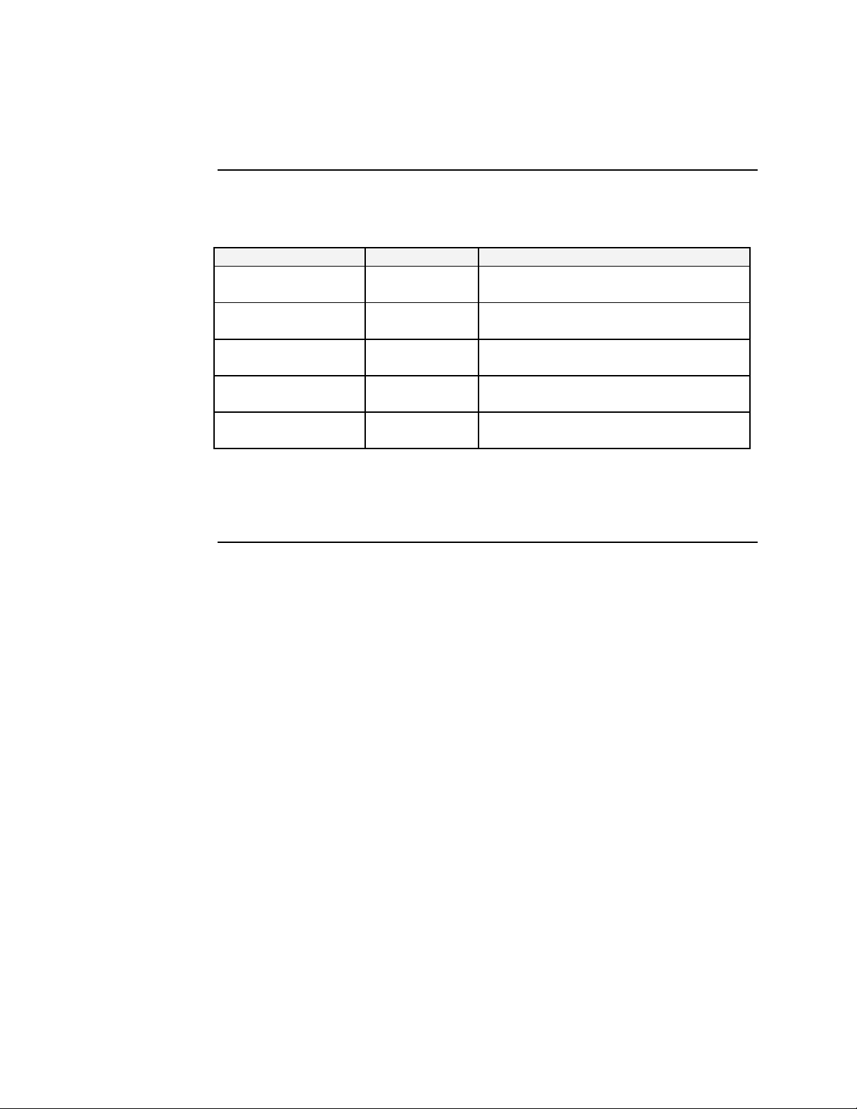
This manual has a beginning table of contents; also, at the beginning of each section
there is a table of contents. As you traverse the manual, note the side headings. These
side headings make it easier to find specific information. The manual sections are as
follows:
Section Description
I Device Server general and physical descriptions, and features.
II Installation: describes mounting and wiring the Device Server for
operation.
III Operation: LED functionality and configuration software.
IV How to instruction on: Serial IP Redirector Software installation,
software upgrades, and creating virtual COM ports.
V Troubleshooting: in a table format, show problem causes and
potential solutions.
VI Cable Specifications: presents RS-232 serial cable and fiber cable
specifications.
VII Tells how to contact Transition Networks, product warranty and
product conformity information.
Appendix A Presents product specifications, notices, and warnings.
Index Provides navigation information to specific content in this manual.
Continued on next page
vi
24-Hour Technical Support: 1-800-260-1312 International: 00-1-952-941-7600
Page 9

SDSFE31xx-100 Industrial Device Server Transition Networks
About this product and manual, continued
Box contents
The box should include the following:
• One RS-232-to-100Base-FX Industrial Device Server
• DIN Rail Kit
• Fiber protective port caps
• User manual CD
• Serial IP Redirector software CD
24-Hour Technical Support: 1-800-260-1312 International: 00-1-952-941-7600
vii
Page 10

Transition Networks SDSFE31xx-100 Industrial Device Server
Cautions and warnings
Cautions and
warnings
Cautions
Make sure that you read and understand all content identified by these two symbols:
Cautions and warnings appear here and throughout this manual where appropriate.
Failure to read and understand the information identified by the “caution” and
“warning” symbols could result in poor equipment performance, damage to
equipment, or injury to persons.
Cautions indicate the possibility of damage to equipment.
CAUTION
Make sure that the Device Server is mounted with proper space around it for
ventilation (heat dissipation). Failure to observe this caution could result in
damage to the Device Server.
CAUTION
Please exercise caution when using power tools. Do not install this unit in damp
or wet locations, or in close proximity to very hot surfaces. Failure to observe
this caution could result in damage to the Device Server and cables.
CAUTION
Only qualified persons should install the Device Server. Failure to observe this
caution could result in poor performance or damage to the Device Server.
CAUTION
Install the Device Server in an environment where the temperature range is from
0ºC to 70ºC (32º to 158º F), with relative humidity of 5% to 90%, noncondensing. Failure to observe this caution could result in poor Device Server
performance.
CAUTION
DO NOT install the Device Server in areas where strong electromagnetic fields
(EMF) exist. Failure to observe this caution could result in poor Device Server
performance and data corruption.
CAUTION
The Device Server must be mounted to a well-grounded surface. Failure to
observe this caution could result in EMI problems.
Continued on next page
viii
24-Hour Technical Support: 1-800-260-1312 International: 00-1-952-941-7600
Page 11
SDSFE31xx-100 Industrial Device Server Transition Networks
Cautions and warnings, continued
CAUTION
When connecting DC power wires to the terminal-block plug, pay close
attention to the polarity markings shown near the terminal block of the Device
Server. Failure to observe this caution could result in damage to the equipment.
CAUTION
This is a Class A product. In a domestic environment, this product could cause
radio interference in which case the user may be required to take adequate
corrective measures.
Warnings
Warnings indicate the possibility of injury to persons.
WARNING
Be sure to disconnect power before installing and wiring the Device Server.
Failure to observe this warning could result in an electrical shock.
WARNING
Fiber optics: Visible and invisible laser radiation when open: DO NOT stare
into the beam, or directly view the beam with optical instruments. Failure to
observe this warning could result in an eye injury or blindness.
WARNING
Use of controls, adjustments or the performance of procedures other than those
specified herein may result in hazardous radiation exposure.
24-Hour Technical Support: 1-800-260-1312 International: 00-1-952-941-7600
ix
Page 12

Transition Networks SDSFE31xx-100 Industrial Device Server
Intentionally Blank
x
24-Hour Technical Support: 1-800-260-1312 International: 00-1-952-941-7600
Page 13

SDSFE31xx-100 Industrial Device Server
In this section
Section I
These are the topics:
Topic See Page
General description 2
SDSFE31xx-100 Industrial part numbers 3
Physical description 4
Page 14

Transition Networks SDSFE31xx-100 Industrial Device Server
General description
Overview
Features
The SDSFE31xx-100 Industrial Device Server features complete Ethernet and
TCP/IP network support that allows devices in industry with RS-232 connectors,
(milling machines, measurement instruments, and robots) to connect to LAN-based
automation. Other devices typically found on campus networks such as card readers,
code readers, lab equipment, medical equipment, and other similar serial devices can
now instantly migrate to a TCP/IP network.
Additionally, the Device Server enables monitoring and managing up to 4,096 serial
devices from a single PC, with help from the serial IP Redirector software.
The SDSFE31xx-100 Industrial Device Server has the following operational
features:
• Fast Ethernet fiber port, 100Mbps
• Serial port with asynchronous data rates up to 115.2 Kbps
• Relay output for power failure and link down
• ST/SC connectors for multimode or SC connector for single mode
• Extends distance of up to 2km (1.2 miles) multimode fiber and 80 km (49.7 miles)
long-haul single mode fiber
• DIP switches to enable/disable alarm function
• Seven (7) LEDs for at-a-glance device status
• Suitable for industrial harsh environments
• Wide voltage range 9 – 48VDC
• Dual (redundant) DC power inputs
2
24-Hour Technical Support: 1-800-260-1312 International: 00-1-952-941-7600
Page 15
SDSFE31xx-100 Industrial Device Server Transition Networks
SDSFE31xx-100 Industrial part numbers
Standard
models
The part numbers shown in Table 1 perform as described in this manual.
Table 1: SDSFE31xx-100 Industrial Part Numbers
Part Number Port 1: DB-9 Port 2: Fiber Optic 100Base-FX
SDSFE3111-100 RS-232 15 m
(50 ft)
SDSFE3113-100 RS-232 15 m
(50 ft)
SDSFE3114-100 RS-232 15 m
(50 ft)
SDSFE3115-100 RS-232 15 m
(50 ft)
SDSFE3117-100 RS-232 15 m
(50 ft)
Note: The distances for ports 1 and 2 listed in Table 1 are typical maximum
distances; the physical characteristics of the network will affect the actual
distances.
ST, 1300 nm multimode
2 km (1.2 miles)
SC, 1300 nm multimode
2 km (1.2 miles)
SC, 1310 nm single mode
20 km (12.4 miles)
SC, 1310 nm single mode
40 km (24.8 miles)
SC, 1550 nm single mode
80 km (49.7 miles)
24-Hour Technical Support: 1-800-260-1312 International: 00-1-952-941-7600
3
Page 16
Transition Networks SDSFE31xx-100 Industrial Device Server
Physical description
Device server
parts and
functions
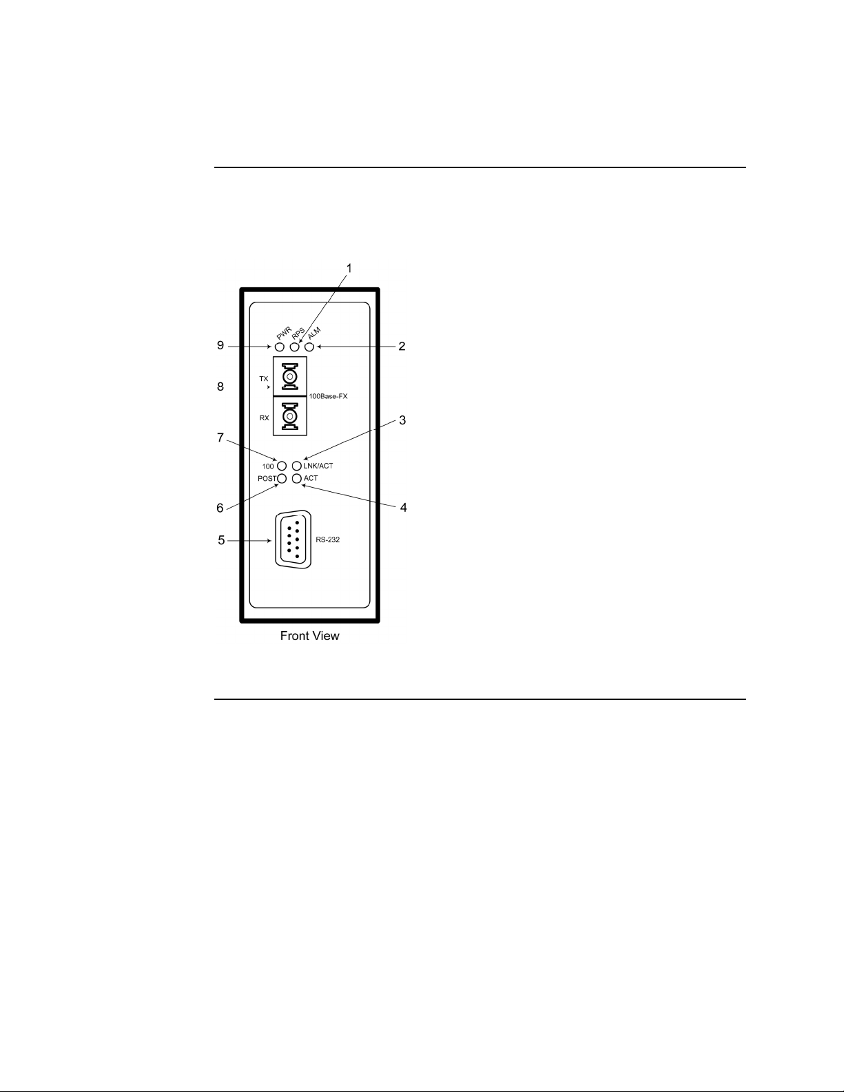
Figures 1 and 2 identify the SDSFE31xx-100 Industrial Device Server parts and
functions.
1. Redundant Power (RPS) LED
2. Alarm LED
3. Fiber Port Link/Activity
4. Serial Port Activity
5. RS-232 Serial Port
6. Power ON and Self-Test (POST) LED
7. Fiber Port 100Mbps LED
8. Fiber Port
9. Primary Power LED
4
Figure 1: SDSFE31xx-100 Industrial Device Server (Front View)
Continued on next page
24-Hour Technical Support: 1-800-260-1312 International: 00-1-952-941-7600
Page 17
SDSFE31xx-100 Industrial Device Server Transition Networks
Physical description, continued
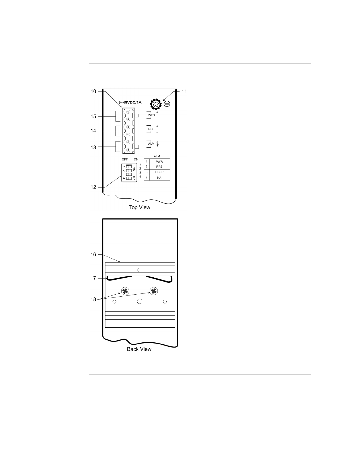
Device server parts and functions (continued)
10. Terminal Bock
11. Grounding Screw
12. DIP Switches
13. Alarm Relay Contacts
14. Redundant Power Input
15. Primary Power Input
16. DIN Rail Bracket
17. Metal Spring
18. Screws
Figure 2: SDSFE31xx-100 Industrial Device Server (Top and Back Views)
24-Hour Technical Support: 1-800-260-1312 International: 00-1-952-941-7600
5
Page 18

Transition Networks SDSFE31xx-100 Industrial Device Server
Intentionally Blank
6
24-Hour Technical Support: 1-800-260-1312 International: 00-1-952-941-7600
Page 19

In this section
Section II
Installation
These are the topics:
Topic See Page
Device Server mounting location 8
DIN rail clip and DIN rail mounting 9
Grounding the Device Server 11
Connecting power to the Device Server 12
Connecting an alarm fixture 15
Connecting fiber cables 17
Connecting DB-9 cable 18
DIP switches 19
Page 20

Transition Networks SDSFE31xx-100 Industrial Device Server
Device Service mounting location
Installation
considerations
Installation
cautions
The location selected to install the Device Server can greatly affect its performance.
When selecting a site, consider the following:
• Install the Device Server in a fairly cool and dry place. See Technical
Specifications for the acceptable temperature and humidity operating ranges.
• Install the Device Server in a location free from strong electromagnetic field
generators (such as motors).
• Do not expose or subject the Device Server to vibration, dust, and direct exposure
to sunlight.
• Leave at least 5cm (1.97 in) of space at the front and rear of the unit for
ventilation.
• To prevent the Device Server from sliding around affix the provided rubber pads
to the bottom plate or mount the device to a DIN Rail.
Observe the following cautions when installing the Device Server.
CAUTION
Only qualified persons should install the Device Server. Failure to observe this
caution could result in poor performance or damage to the Device Server.
CAUTION
Install the Device Server in an operating environment where the temperature
range is from 0ºC to 70ºC (32º to 158º F), with relative humidity of 5% to 90%,
non-condensing. Failure to observe this caution could result in poor Device
Server performance.
CAUTION
DO NOT install the Device Server in areas where strong electromagnetic fields
(EMF) exist. Failure to observe this caution could result in poor Device Server
performance and data corruption.
8
24-Hour Technical Support: 1-800-260-1312 International: 00-1-952-941-7600
Page 21
SDSFE31xx-100 Industrial Device Server Transition Networks
DIN rail clip and DIN rail mounting
Mounting the
DIN rail clip
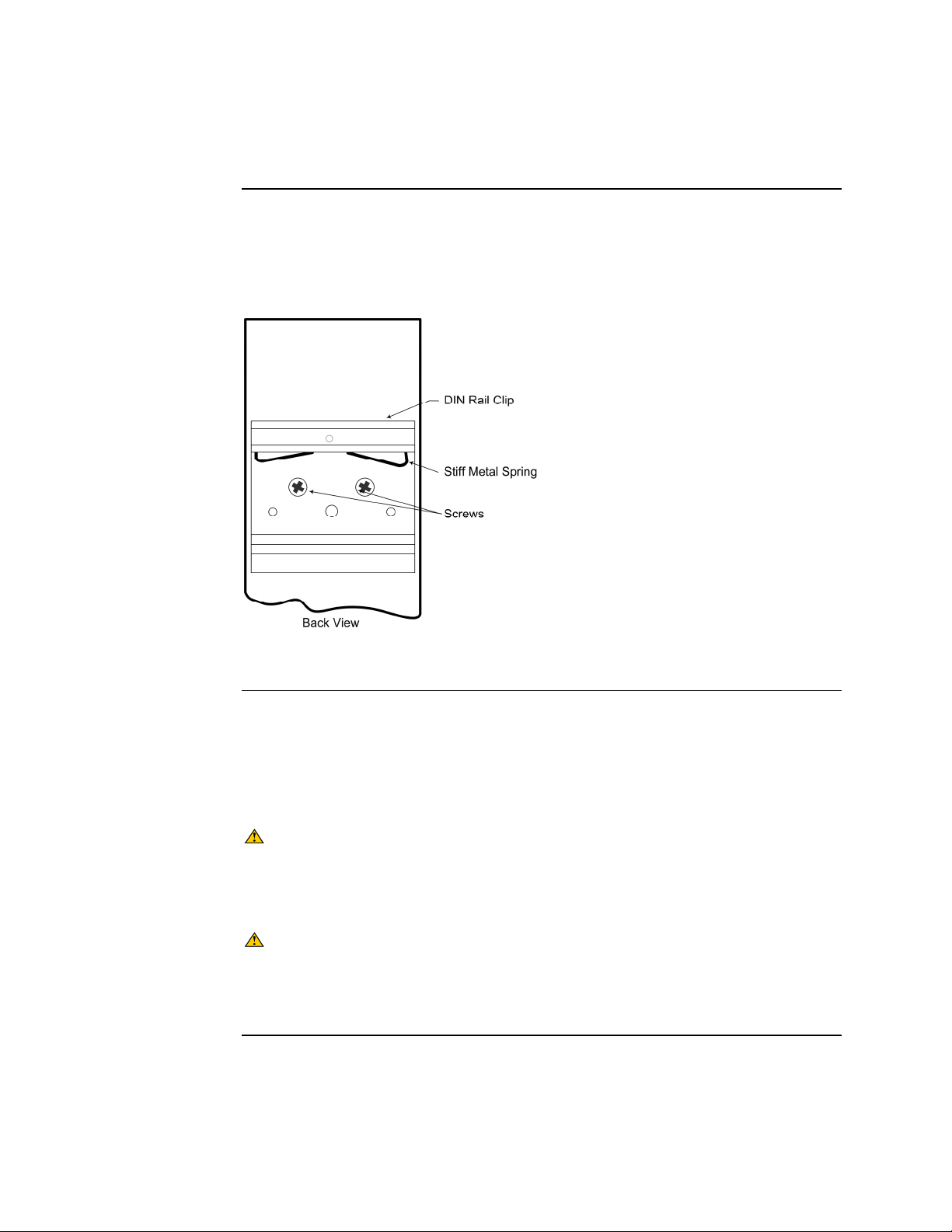
The aluminum DIN Rail Clip should already be mounted to the back panel of the
Device Server. If you need to attach the DIN Rail Clip, position the stiff-metal spring
as shown in Figure 3.
DIN rail and
device server
mounting
considerations
Figure 3: Mounted DIN Rail Clip
Consider the following before mounting the DIN rail to a surface and attaching the
Device Server:
• The surface must support at least 1,000 gm (2.2 lbs) for the Device Server.
• Do not place heavy objects on the Device Server.
CAUTION
Mount the Device Server with proper spacing around it for ventilation (heat
dissipation). Failure to observe this caution could result in damage to the
Device Server.
CAUTION
Please exercise caution when using power tools. Do not install this unit in damp
or wet locations, or in close proximity to very hot surfaces. Failure to observe
this caution could result in damage to the Device Server and cables.
Continued on next page
24-Hour Technical Support: 1-800-260-1312 International: 00-1-952-941-7600
9
Page 22
Transition Networks SDSFE31xx-100 Industrial Device Server
DIN rail clip and DIN rail mounting, continued
Mounting the
device server
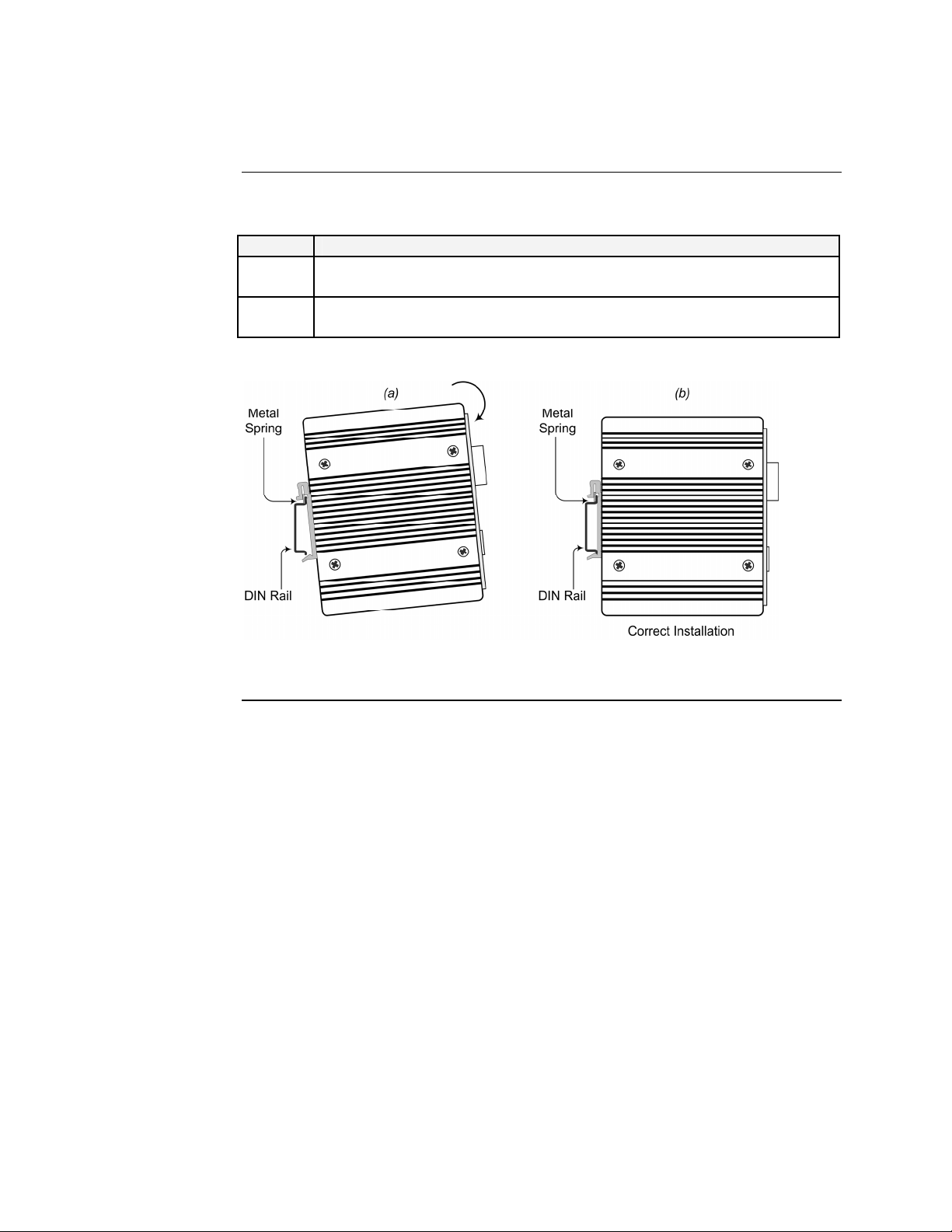
To mount the Device Server to the DIN rail, see Figure 4 and do the following:
Step Action
1. Align and then position DIN-Rail-clip spring to the top of the DIN rail as
shown in Figure 4a.
2. Press DOWN on the Device Server and then IN to snap it into place on
the DIN Rail. See Figure 4b.
Figure 4: Device Server Mounting to DIN Rail
10
24-Hour Technical Support: 1-800-260-1312 International: 00-1-952-941-7600
Page 23
SDSFE31xx-100 Industrial Device Server Transition Networks
Grounding the Device Server
WARNING
Be sure to disconnect power before installing and wiring the Device Server.
Failure to observe this warning could result in an electrical shock.
Wiring
considerations
The following wiring considerations are recommended:
• Use separate paths to route wiring for power and device data cables. If power
wiring and device data cables must cross make sure that the wires are
perpendicular at the intersection point.
• Do not run signal or communications wiring and power wiring in the same wire
conduit. To avoid interference, wires with different signal characteristics route
separately.
• Use the type of signal transmitted through a wire to determine which wires should
be kept separate. The rule of thumb is wiring that shares similar electrical
characteristics can be bundled together.
• Keep input and output wiring separated.
• Label the wiring to all devices in the system for clarity.
Device server
grounding
CAUTION
The Device Server must be mounted to a well-grounded surface. Failure to
observe this caution could result in EMI problems.
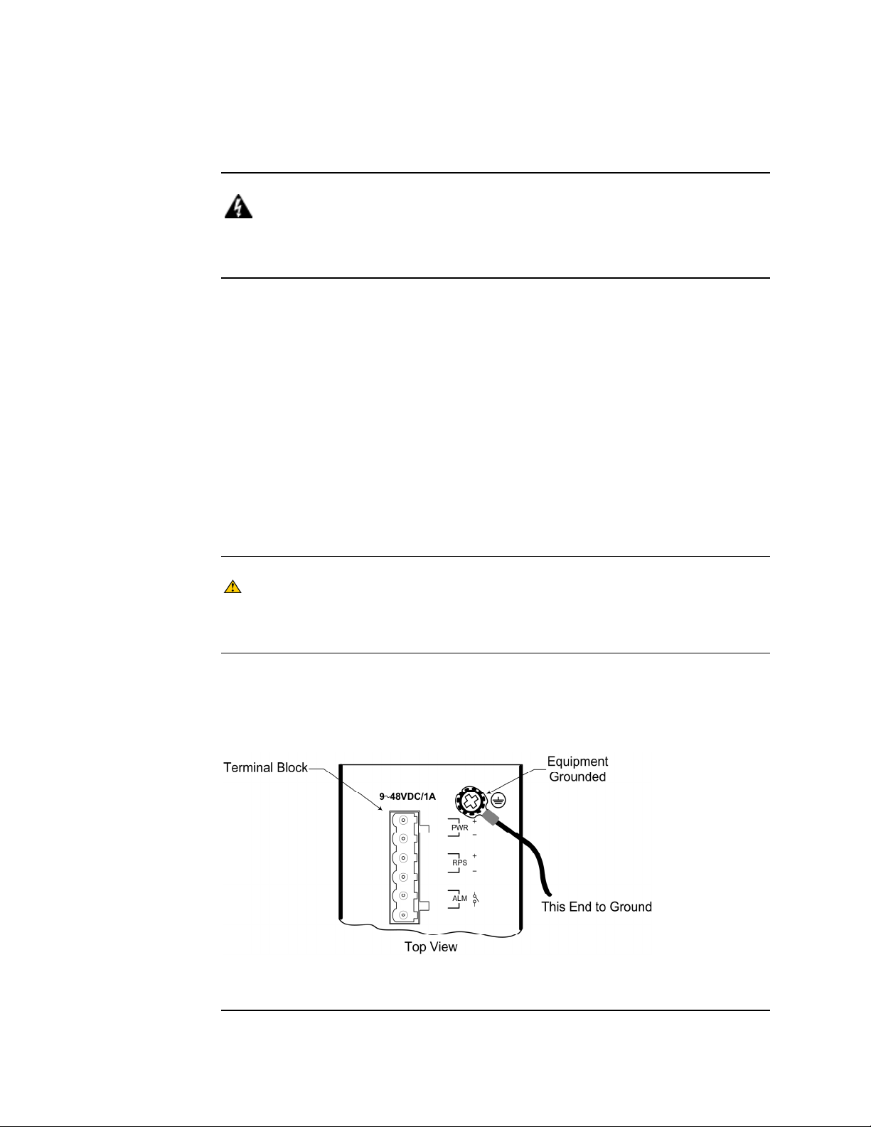
The Device Server can eliminate the effects of noise due to electromagnetic
interference (EMI) via proper grounding. Always run the ground connection from
the ground screw to a grounding surface before connecting DC power. See Figure 5.
Figure 5: Device Server Grounding Screw
24-Hour Technical Support: 1-800-260-1312 International: 00-1-952-941-7600
11
Page 24
Transition Networks SDSFE31xx-100 Industrial Device Server
Connecting power to the Device Server
Redundant
power
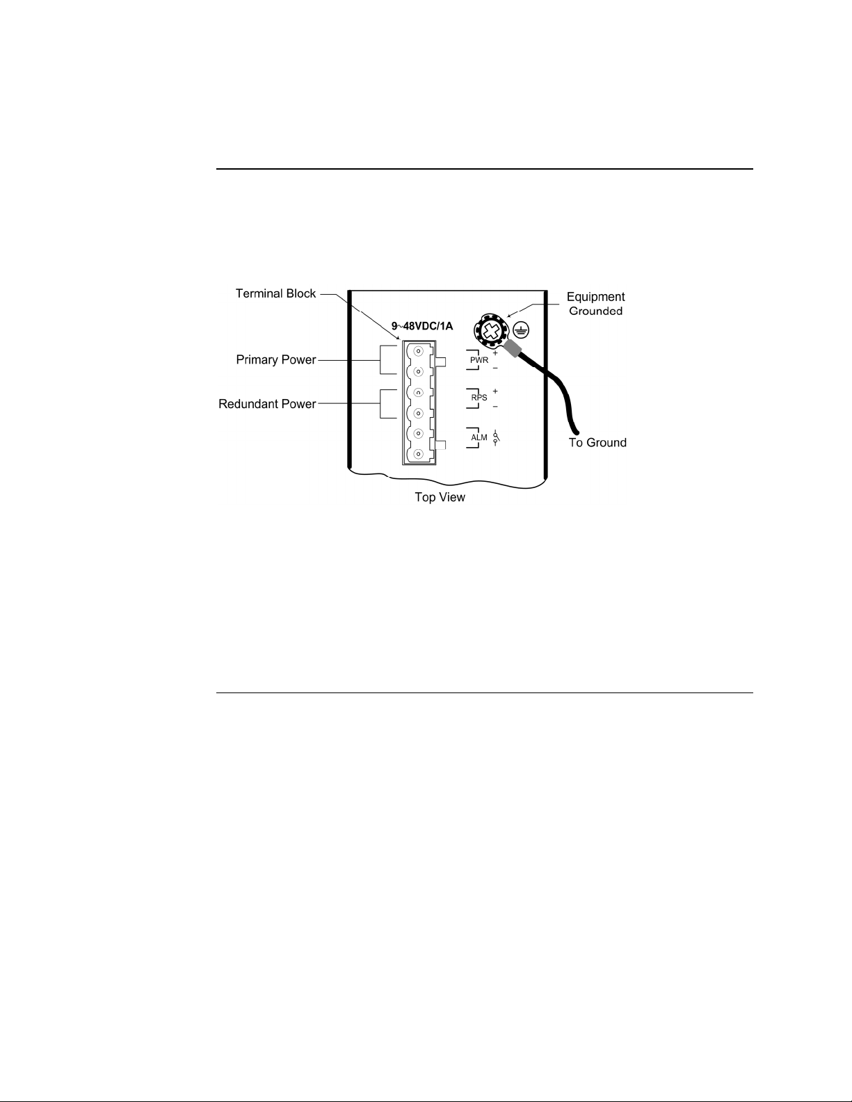
Dual (redundant) power inputs can be connected simultaneously to live DC power
sources. See Figure 6. If one power source fails, the other live source acts as a
backup, and automatically supplies the Device Server with power.
Figure 6: Redundant Power Connections
IMPORTANT
• Power is supplied through an external DC power source. Check the Technical
Specification section for information about the DC power input voltage.
•
The Device Server does not include a power switch; therefore, plugging a wired
and active terminal-block plug into its terminal block will immediately power UP
the unit.
Continued on next page
12
24-Hour Technical Support: 1-800-260-1312 International: 00-1-952-941-7600
Page 25
SDSFE31xx-100 Industrial Device Server Transition Networks
Connecting power to the Device Server, continued
CAUTION
When connecting DC power wires to the terminal-block plug, pay close
attention to the polarity markings shown near the terminal block of the Device
Server. Failure to observe this caution could result in damage to the device.
Terminal-block
plug wiring
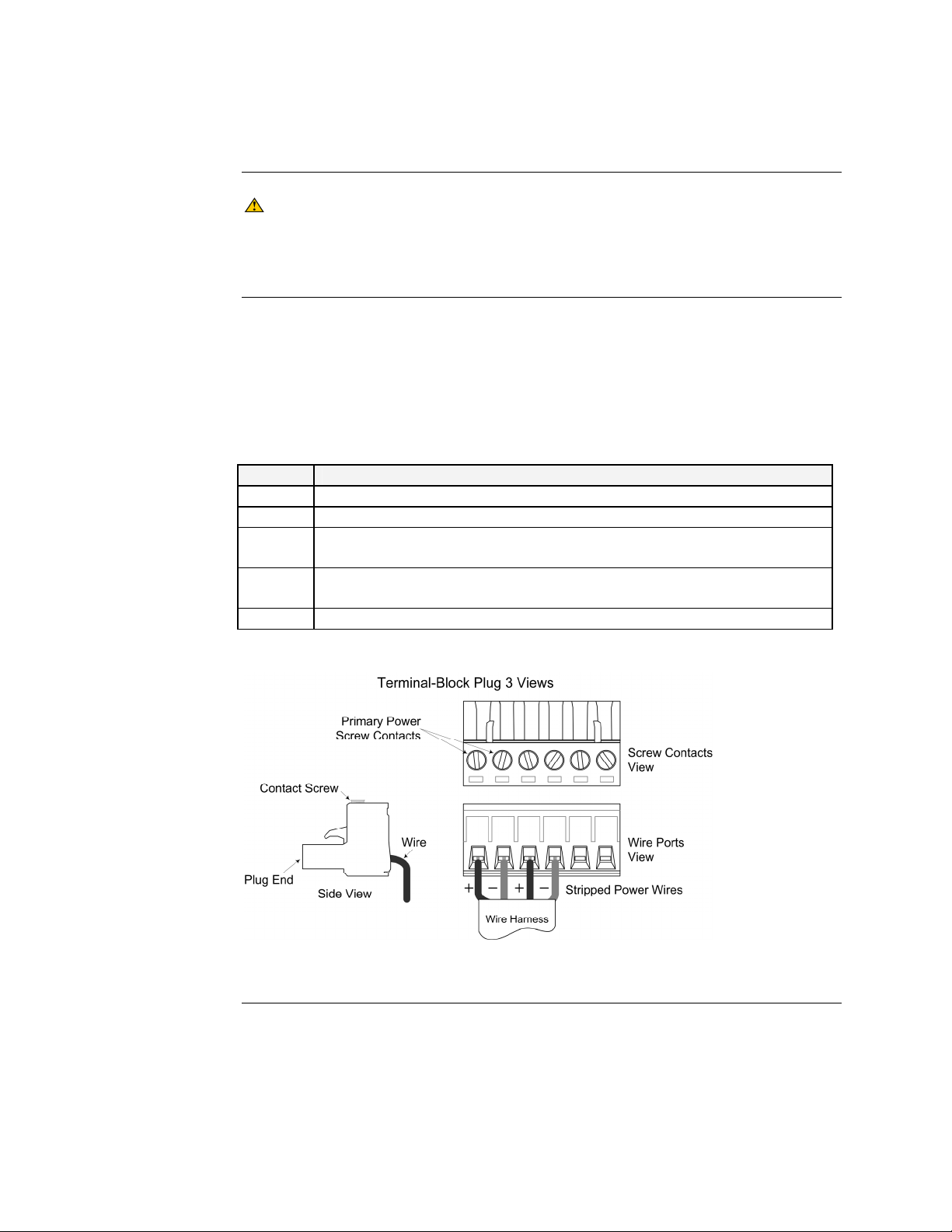
To wire the six-contact-terminal-block plug for redundant power, do the following:
Note: The six-contact-terminal-block plug is constructed (keyed) to mate with the
Device Server terminal block. When wiring the plug for power, use the
polarity markings next to the terminal block on top of the Device Server to
ensure proper connection.
Step Action
1. Turn the external power source OFF.
2. Strip the power wires as required.
3. Insert one stripped power wire into the terminal-block plug, Observe
polarity. See Figure 7.
4. Secure the wire using a flathead screwdriver by tightening the contact
screw. See Figure 7.
5. Repeat Steps 3 and 4 until all wires are installed and secured.
Figure 7: Six-Contact-Terminal-Block Plug (Primary/Redundant Power Wiring)
24-Hour Technical Support: 1-800-260-1312 International: 00-1-952-941-7600
Continued on next page
13
Page 26
Transition Networks SDSFE31xx-100 Industrial Device Server
Connecting power to the Device Server, continued
Terminal-block plug wiring (continued)
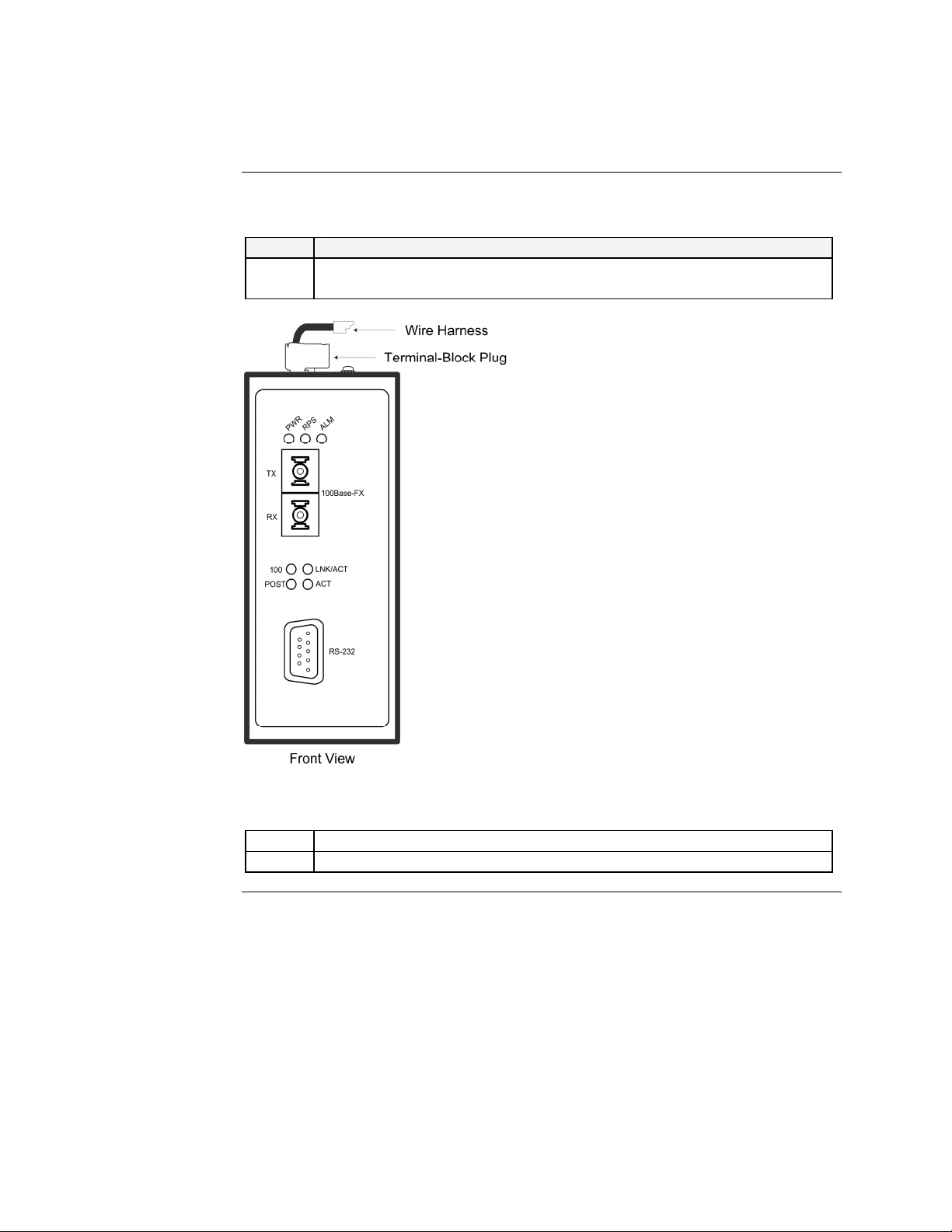
Step Action
6. Insert the terminal-block plug into the Device Server’s terminal block, as
shown in Figure 8.
14
Figure 8: Wired Terminal-Block Plug Inserted Into Device Server
7. Make sure that the DC power source is stable and clean.
8. Turn ON the power source and the PWR LED(s) should turn ON.
24-Hour Technical Support: 1-800-260-1312 International: 00-1-952-941-7600
Page 27

SDSFE31xx-100 Industrial Device Server Transition Networks
Connecting an alarm fixture
Alarm relay
The Device Server has contacts for connecting an external alarm fixture. Located on
the green terminal block on the top panel, the relay has normally open contacts that
can be wired to form a circuit for triggering an external alarm when a fault occurs
(light or audible alarm). See Figure 9.
Alarm relay
wiring
Figure 9: Alarm Relay Contacts
To wire an alarm to the relay contacts, do the following:
Step Action
1. Verify that the external power source is turned OFF.
2. Strip the wires as required.
3. Wire the alarm as shown in Figure 10.
Figure 10: Alarm Relay Wiring
24-Hour Technical Support: 1-800-260-1312 International: 00-1-952-941-7600
Continued on next page
15
Page 28

Transition Networks SDSFE31xx-100 Industrial Device Server
Connecting an alarm fixture, continued
Fault
indications
Wire the relay contacts to any warning light or audible alarm in the factory or control
room. Then when a fault occurs, the relay contacts close, sending a signal to activate
an external alarm or turn ON a light, indicating a fault. An alarm will occur under
the following conditions:
• Any link failure cable disconnected, device break down .....)
•
PWR/RPS power failure:
o Power wires are disconnected, power source malfunction
o Input power is out of this range: 9 – 48V
16
24-Hour Technical Support: 1-800-260-1312 International: 00-1-952-941-7600
Page 29

SDSFE31xx-100 Industrial Device Server Transition Networks
Connecting fiber cables
Fiber cable
installation
When connecting fiber cables to the 100BASE-FX port on the Device Server, make
sure the correct type is used: ST or SC.
To install the fiber cables, do the following:
Step Action
1. Remove and keep the rubber fiber-port-protector cover shown below.
Note: When not connected to a fiber cable, insert the rubber protective cover into
optic port to protect the optics.
2. Check that the fiber terminators are clean. If necessary, clean the fiber
connectors using locally accepted cleaning procedures.
Note: Dirty fiber connectors on fiber optic cables will impair light transmission
quality through the cable and lead to degraded performance on the port.
3. Connect the fiber cable as shown in Figure 11.
Figure 11: Fiber Cable Connections
4. Check the corresponding fiber port LED on the Device Server to verify
the connection—Link/Act LED should be lit.
Warning
• Visible and invisible laser radiation when open: DO NOT stare into the
beam, or directly view the beam with optical instruments. Failure to observe
this warning could result in an eye injury or blindness.
• Use of controls, adjustments or the performance of procedures other than
those specified herein may result in hazardous radiation exposure.
24-Hour Technical Support: 1-800-260-1312 International: 00-1-952-941-7600
17
Page 30

Transition Networks SDSFE31xx-100 Industrial Device Server
Connecting DB-9 cable
DB-9 cable
configuration
Depending on the equipment type, data terminal equipment (DTE) or data
communication equipment (DCE), use a null modem (crossover) or straight-through
cable. See Figure 13.
Figure 12: Straight Through and Crossover Cables
Note: The Device Server is configured as a DTE Device. See Cable Specification
Section for DB-9 cable pinouts.
DB-9 cable
installation
To connect the DB-9 (RS-232) cable to the Device Server and other equipment, do
the following:
Step Action
1. Insert one end of the RS-232 cable into the Device Server.
2. Tighten the screws to secure the cable.
3. Repeat Steps 1 and 2 for the other equipment. See Figure 12.
4. Test the connection by sending a link pulse to the Device Server and the
ACT LED will flash, indicating a good connection.
Figure 13: DB-9 Cable Installation
18
24-Hour Technical Support: 1-800-260-1312 International: 00-1-952-941-7600
Page 31
SDSFE31xx-100 Industrial Device Server Transition Networks
DIP Switches
DIP switch
position
descriptions
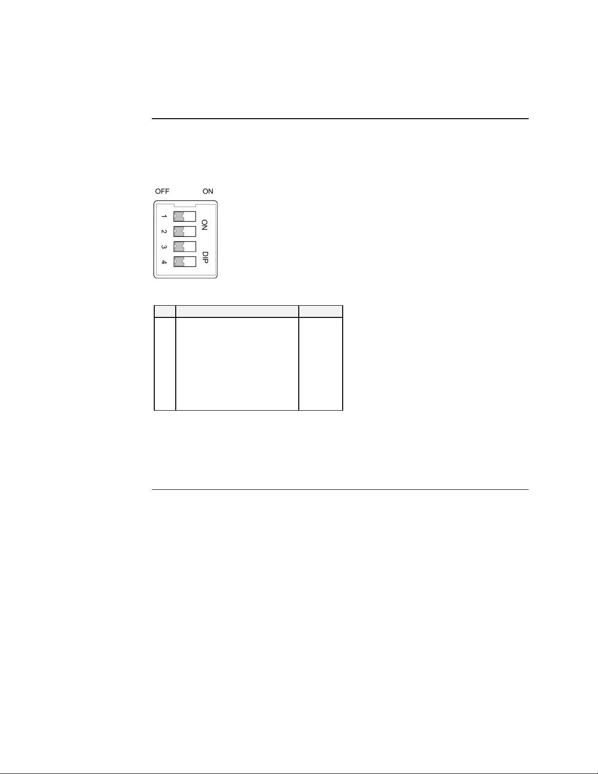
The Device Server features four DIP switches on the top panel that set the responds
for the alarm in case of power loss or link failure. Figure 14 shows the DIP switch
and a chart that explains each setting.
No Description Default
1
Primary power alarm
(enable ON, disable OFF)
2
Redundant power alarm
(enable ON disable OFF)
3
Fiber port alarm
(enable ON disable OFF)
4
N/A
OFF
OFF
OFF
OFF
Figure 14: Dip Switch Settings and Explanations
Note: DIP switch changes will not become active until the Device Server is power
cycled (turned OFF then ON).
24-Hour Technical Support: 1-800-260-1312 International: 00-1-952-941-7600
19
Page 32

Transition Networks SDSFE31xx-100 Industrial Device Server
Intentionally Blank
20
24-Hour Technical Support: 1-800-260-1312 International: 00-1-952-941-7600
Page 33

In this section
Section III
Operations
These are the topics:
Topic See Page
Light Emitting Diodes (LEDs) 22
Device Server configuration 23
Configuration software 25
Page 34

Transition Networks SDSFE31xx-100 Industrial Device Server
Light emitting diodes (LEDs)
LEDs
The Device Server has LED indicators located on its front panel. The LEDs present
at-a-glance network status, and provide real-time connectivity information. Figure 15
shows the LEDs and a chart that explains the function of each.
LED Description
1 Power (PWR) Lights green when input power is good
2 Redundant Power (RPS) Lights green when receiving external power from
redundant input source
3 Alarm (ALM) Lights red, signaling an alarm (when an external
alarm is connected) during a down link condition on
any port, or during primary/redundant power failures
4 LNK/ACT Lights green when connected to another device.
Flashes (amber) to indicate when the fiber port
receives link pulses from a compliant device (fiber
port only).
5 ACT Lights to indicate when the serial port is receiving
link pulses or data from a compliant device
6 POST Lights (amber) when the Power on Self Test was
successful; flashes when performing the POST
7 100 Lights (amber) to indicate when receiving data from
at 100Mbps (fiber port only)
Figure 15: LEDs and Description Chart
22
24-Hour Technical Support: 1-800-260-1312 International: 00-1-952-941-7600
Page 35
SDSFE31xx-100 Industrial Device Server Transition Networks
Device Server configuration
Introduction
Web access
Use a web browser to configure the Device Server. You can set the TCP/IP
configuration for the device to monitor and manage attached Serial Devices via
Serial IP Redirector software.
Once connected to a network, the Device Server is accessible via a web browser.
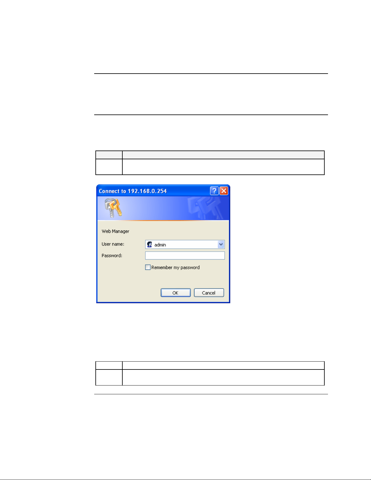
To access the Device Server via a web browser, do the following:
Step Action
1. Type the default IP 192.168.0.254 address (if connecting with the default
IP) at web browser to launch the login dialog box. See Figure 16.
Figure 16: Login Dialog Box
Note: The default user name is “admin;” no password has been assigned. However,
you can change the user name and password within the GUI via submenu
item “User Config.”
2. Enter default user name “admin” as shown in Figure 16.
3. Click the OK button to launch the Device Server’s graphical user
interface (GUI) main menu screen, shown in Figure 17.
24-Hour Technical Support: 1-800-260-1312 International: 00-1-952-941-7600
Continued on next page
23
Page 36
Transition Networks SDSFE31xx-100 Industrial Device Server
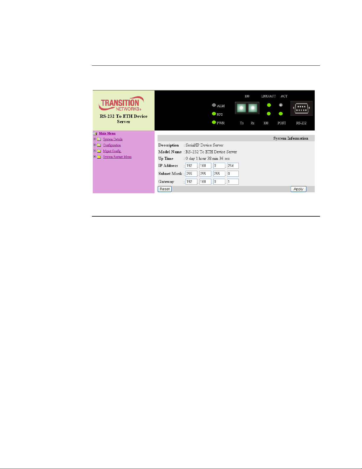
Device Server configuration, continued
Web access (continued)
Figure 17: Main Menu Screen
24
24-Hour Technical Support: 1-800-260-1312 International: 00-1-952-941-7600
Page 37
SDSFE31xx-100 Industrial Device Server Transition Networks
Configuration software
Expanded
software tree
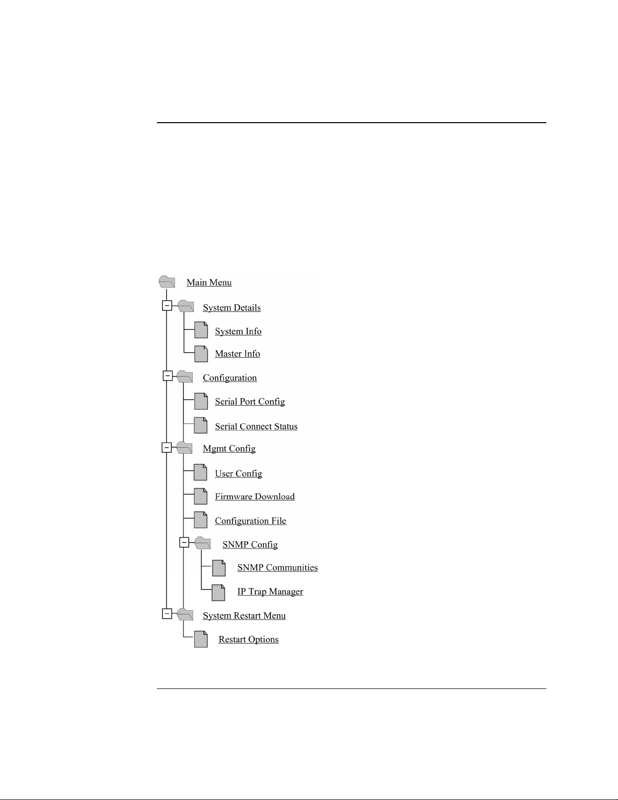
On the left side of the GUI screen, under the Transition logo, are five menu items:
• System Details
• Configuration
• Mgmt Config
• SNMP
• System Restart
Figure 18 shows the expanded software tree; an explanation of each menu option
starts on the following page.
Figure 18: Expanded Configuration Software Tree
24-Hour Technical Support: 1-800-260-1312 International: 00-1-952-941-7600
Continued on next page
25
Page 38
Transition Networks SDSFE31xx-100 Industrial Device Server
Configuration software, continued
Systems details
menu options
Click the Systems Details
• System Info
• Master Info
link to show its two submenu options:
System
information
submenu
Click the “system info
See Figure 19.
” link to show the Device Server system information submenu.
Master
information
submenu
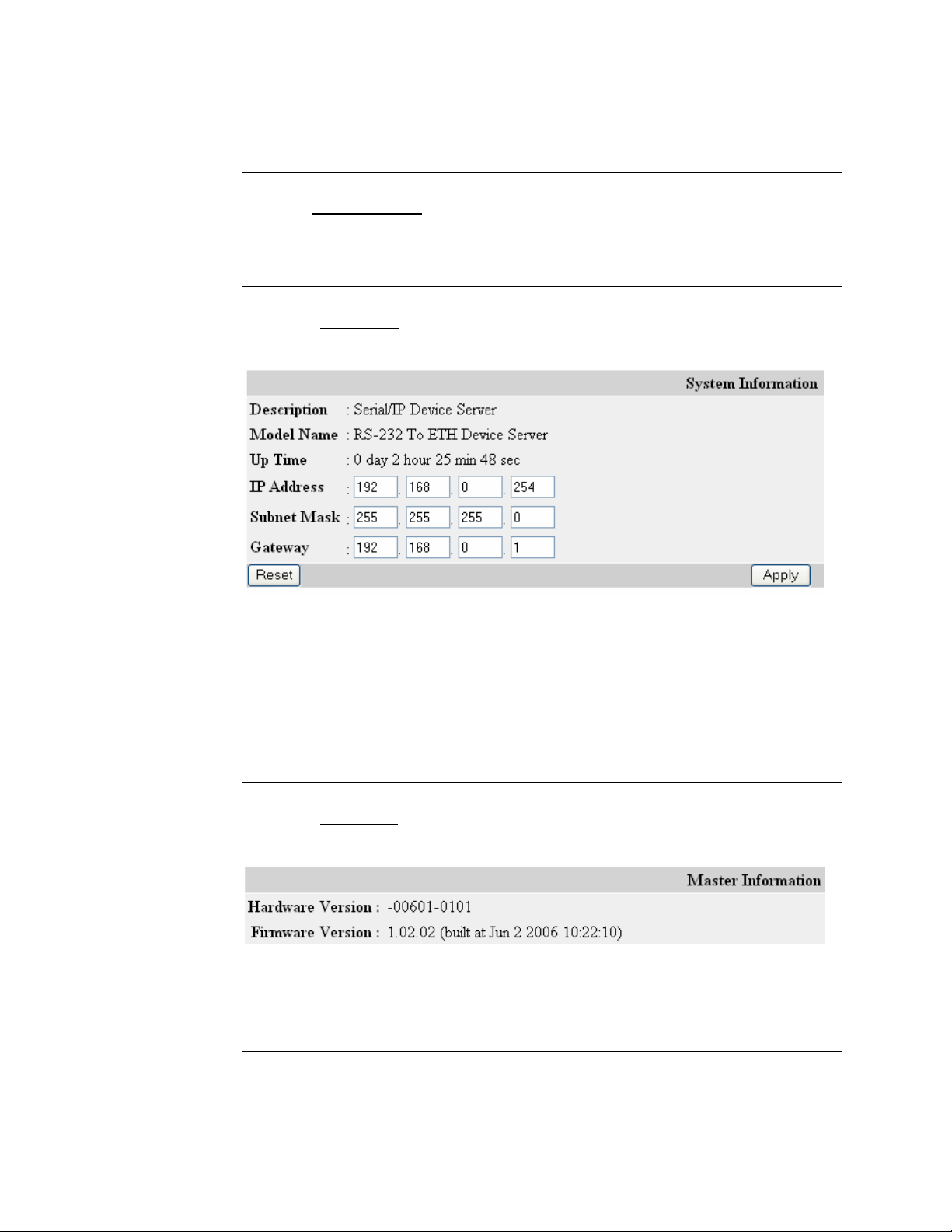
Figure 19: System Info Submenu
This menu option provides a description of the Device Server, model name, along
with the up times (day/hour/minute/second). It also allows editing the IP address,
subnet mask, and gateway.
Click the APPLY button to implement any changes. Click the RESET button to
restore the original settings before applying any changes.
Click the “master info
only submenu. See Figure 20.
Figure 20: Master Information Read Only Submenu
This read-only menu displays the hardware and firmware versions.
” link to launch the Device Server master information read
Continued on next page
26
24-Hour Technical Support: 1-800-260-1312 International: 00-1-952-941-7600
Page 39

SDSFE31xx-100 Industrial Device Server Transition Networks
Configuration software, continued
Configuration
menu options
Click the Configuration
• Serial Port Config
• Serial Connect Status
link to show its two submenu options:
Serial port
config submenu
Click the “serial port config
configuration submenu. See Figure 21.
” link to launch the Device Server serial port
Figure 21: Serial Port Transfer Configuration Submenu Display
Use this menu to configure server/client mode and the serial port. This menu shows
the serial port configuration, and allows configuring all fields.
When using a serial device with Modbus RTU protocol, “enable” Packet mode for
the serial input. Also, enter an appropriate inter-packet timeout value to facilitate
smooth data communications. Click the APPLY button to save and activate the
changes. Click the RESET button to return to the previous settings before applying
the changes.
The following explains the server/client mode configuration submenu items.
24-Hour Technical Support: 1-800-260-1312 International: 00-1-952-941-7600
Continued on next page
27
Page 40

Transition Networks SDSFE31xx-100 Industrial Device Server
Configuration software, continued
Serial port config submenu (continued)
Submenu Item Description
Server/Client Type Defines whether the Device Server is acting as a
server or a client. In Device Server Mode, this
setting will always be Server. In Converter Mode,
this setting can be either Server or Client.
Remote IP In Converter Mode, enter the IP address of the
remote device. This field is NOT USED in Device
Server Mode.
TCP Port Number Device Server mode (DS): the TCP port number is
the number that the Device Server uses to listen for
connections; also, other devices must use this port
to contact the Device Server.
Converter mode:
number to communicate with the host.
Connection Idle Time This setting only applies to Converter Mode. The
time value (in seconds) is the maximum time that
the TCP port will remain open with no activity.
Once the time value is reached, the Device server
closes the port to prevent the port from remaining
open indefinitely. This field is NOT USED in
Device Server mode.
DS/CR Modes Device server (DS) mode, also know as TCP/IP
mode, is used to connect a serial device to a host via
an Ethernet network. This mode allows using an
existing COM-port-based software platform across
an existing Ethernet LAN. See Figure 22.
both converters use the TCP port
28
Figure 22: Serial Device Connection to a Host via Ethernet Network
Continued on next page
24-Hour Technical Support: 1-800-260-1312 International: 00-1-952-941-7600
Page 41

SDSFE31xx-100 Industrial Device Server Transition Networks
Configuration software, continued
Serial port config submenu (continued)
Submenu Item Description
DS/CR Modes (continued) Converter Mode (CR) is used for serial tunneling
across an Ethernet network between two serial ports
to simulate a direct serial connection between the
devices. See Figure 23.
Figure 23: Serial Tunneling
Packet Mode of Serial
Input (enable/disable)
Packet Mode Inter-Packet
Timeout
Default is disabled. This will be the setting for the
serial data arriving at the serial port in a bit stream.
Enable if serial data on the serial interface will be in
packet mode.
This time value (in milliseconds) is the delimiter
timeout value between serial packets. This only
applies if packet mode of the serial input is enabled.
The value will largely depend on the serial device
connected to the Device Server or the field bus
protocol used (i.e., Modbus, etc.).
Continued on next page
24-Hour Technical Support: 1-800-260-1312 International: 00-1-952-941-7600
29
Page 42

Transition Networks SDSFE31xx-100 Industrial Device Server
Configuration software, continued
Serial connect
status submenu
Click the “serial connect status
status submenu. See Figure 24.
” link to launch the Device Server serial connection
Figure 24: RS-232 Port Connection Status Submenu Display
This menu provides instant information about serial port connectivity. In this
submenu, you can view a current connection status instance; also, clear the
information on the screen by clicking the CLEAR button. A description of each
menu item is shown below.
Submenu Item Description
Connect Status Server or client.
Peer IP Address
Dest/Srce Port Number
Byte Counts From UART
Byte Counts to Network
Byte Counts From Network
Byte Counts to UART Displays the number of bytes received by the serial
IP of the remote PC that is accessing the device
attached to the Device Server’s serial port.
Shows the destination and source port numbers—
source port number will be as configured.
Displays the number of bytes transmitted from the
serial device.
Displays the number of bytes received on the TCP/IP
network.
Displays the number of bytes transmitted from the
TCP/IP network.
device.
Continued on next page
30
24-Hour Technical Support: 1-800-260-1312 International: 00-1-952-941-7600
Page 43

SDSFE31xx-100 Industrial Device Server Transition Networks
Configuration software, continued
Mgmt config
menu options
Click the Mgmt config
• User Config
• Firmware Download
• Configuration File
• SNMP Config
link to show its four submenu options:
User config
submenu
Click the “user config
See Figure 25.
” link to launch the Device Server user configuration submenu.
Figure 25: User Configuration Submenu
This option allows you to establish a username and password for Device Server
management. To change the user name and password, do the following:
Step Action
1. Type the new user name in the user-name field.
2. Type the password in the password field.
3. Click the APPLY button to set the user name and password.
IMPORTANT
Write down the new user name and password and keep the information in a safe
place. This information will be required in the future to access the management
portion of the software.
Also, use this same user name and password, if established here, in the Redirector
software to communicate with the Device Server.
Continued on next page
24-Hour Technical Support: 1-800-260-1312 International: 00-1-952-941-7600
31
Page 44

Transition Networks SDSFE31xx-100 Industrial Device Server
Configuration software, continued
Firmware
download
submenu
Click the “firmware download
submenu. You can upgrade the firmware (FW) via HTTP or TFTP. See Figure 26.
Figure 26: Firmware Upgrade Submenu
” link to launch the Device Server firmware download
FW upgrade
via HTTP
To upgrade the firmware via HTTP, do the following:
Step Action
1. Click the BROWSE button to locate the firmware, as shown in Figure 27.
32
Figure 27: Choose File Dialog Box
Continued on next page
24-Hour Technical Support: 1-800-260-1312 International: 00-1-952-941-7600
Page 45

SDSFE31xx-100 Industrial Device Server Transition Networks
Configuration software, continued
FW upgrade via HTTP (continued)
Step Action
2. Click the OPEN button on the choose file dialog box to populate the file
name field with the firmware-upgrade address, as shown in Figure 28.
Figure 28: HTTP Firmware File Name Captured
3. Click the START UPGRADE BY HTTP button to start downloading the
firmware and a system upgrade timeout display will appear, as shown in
Figure 29.
Figure 29: System Firmware Upgrade Time Out Display
Continued on next page
24-Hour Technical Support: 1-800-260-1312 International: 00-1-952-941-7600
33
Page 46

Transition Networks SDSFE31xx-100 Industrial Device Server
Configuration software, continued
FW upgrade via HTTP (continued)
When the firmware upgrade is complete, the index page (system information) will
appear, as shown in Figure 30.
FW upgrade
via TFTP
Figure 30: Index Page (System information) Display
Click the serial port config link to modify the configuration, based on the new
firmware.
Note: The firmware file must be stored on the TFTP server before upgrading by this
method can occur.
To upgrade the via TFTP server, do the following:
Step Action
1. Enter the IP address the TFTP server field, as shown in Figure 31.
192 168 0 155
TRANS_601_V122.b
Figure 31: TFTP Upgrade Submenu Display
2. Enter the file name in the file name field, as shown in Figure 31 above.
Continued on next page
34
24-Hour Technical Support: 1-800-260-1312 International: 00-1-952-941-7600
Page 47

SDSFE31xx-100 Industrial Device Server Transition Networks
Configuration software, continued
FW upgrade via TFTP (continued)
Step Action
3. Click the START UPGRADE BY TFTP button to start downloading the
firmware, and a system upgrade timeout display will appear as shown in
Figure 32.
Figure 32: System Firmware Upgrade Time Out Display
When the firmware upgrade is complete, the index page (system information) will
appear, as shown in Figure 33.
Figure 33: Index Page (System information) Display
24-Hour Technical Support: 1-800-260-1312 International: 00-1-952-941-7600
Continued on next page
35
Page 48

Transition Networks SDSFE31xx-100 Industrial Device Server
Configuration software, continued
Configuration
file submenu
Click the “configuration file
submenu, shown in Figure 34.
” link to show the Device Server system backup
Figure 34: Configuration System Backup File Display
Configuration
file backup
To “backup” the configuration file to the local PC, do the following:
Step Action
1. Click the BACKUP SETTING button on the display, and the save
“config file” dialog box will appear, as shown in Figure 35.
36
Figure 35: Save System Backup File Dialog Box
2. Click the SAVE button to save the config file and a prompt will appear
to select a location for storing the file on the local PC.
3. Select the location then click the SAVE button to save the config file.
Continued on next page
24-Hour Technical Support: 1-800-260-1312 International: 00-1-952-941-7600
Page 49
SDSFE31xx-100 Industrial Device Server Transition Networks
Configuration software, continued
Configuration
file restore
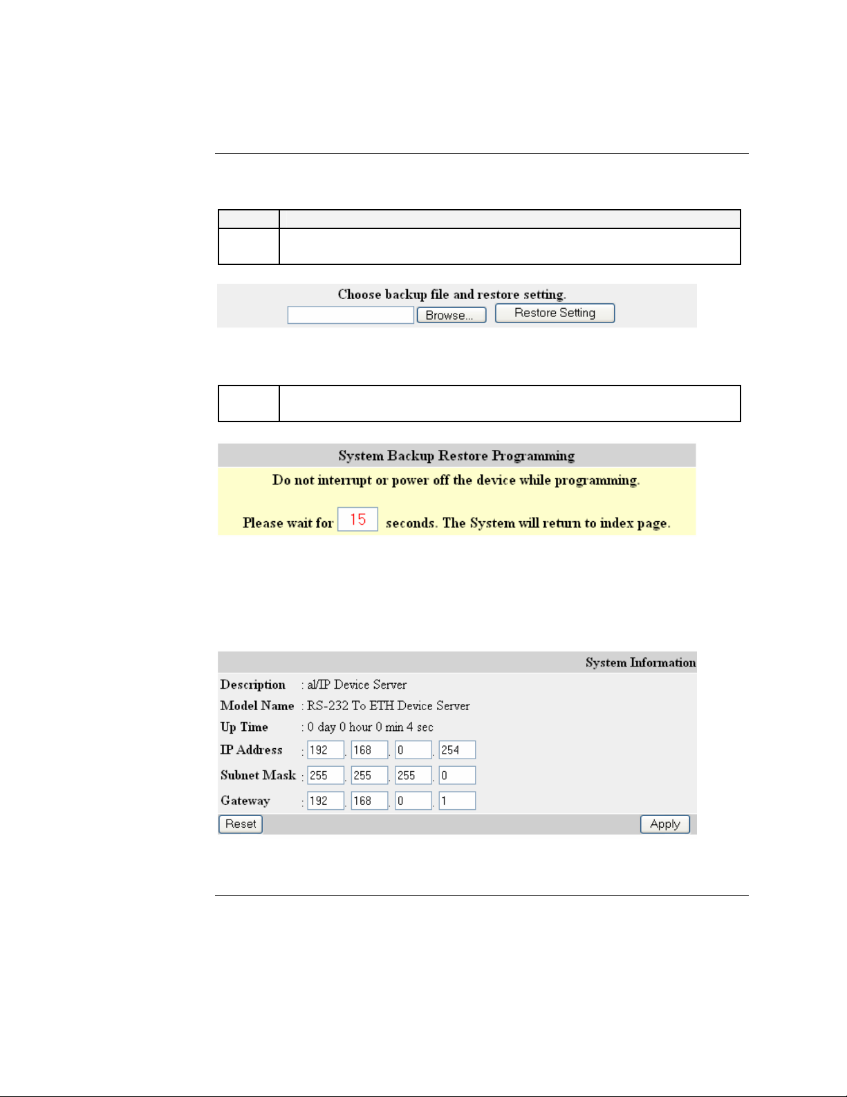
To Restore the backup configuration file, do the following:
Step Action
1. Enter the file name or click the BROWSE button to locate the file. See
Figure 36.
Config. Bin
Figure 36 Backup File Restore Display
2. Click the RESTORE SETTING button, and a restore timeout display
will appear as the backup file is being restored. See Figure 37.
Figure 37: System Backup Restore Timeout Display
When the backup file is restored, the index page (system information) will appear on
the display, as shown in Figure 38.
Figure 38: Index Page (System Information) Display
24-Hour Technical Support: 1-800-260-1312 International: 00-1-952-941-7600
Continued on next page
37
Page 50

Transition Networks SDSFE31xx-100 Industrial Device Server
Configuration software, continued
SNMP
configuration
menu
Click the SNMP config
• SNMP Communities
• IP Trap Manager
link to show its two submenus:
SNMP
communities
submenu
Click the “SNMP Communities
option. See Figure 39.
Figure 39: SNMP Communities Display
” link to launch the SNMP Communities submenu
Use an external SNMP-based application to configure and manage the Device
Server. This management method requires the SNMP agent on the Device Server and
on the SNMP network management station (NMS) to use the same community
string. This management method uses two community strings: “get” community
string and “set” community string:
• If the SNMP NMS knows the “Set” community string, it can read and write to the
MIBs.
• If it only knows the “Get” community string, it can only read MIBs.
The default get and “Set” community strings for the Device Server are “public” and
“private” respectively.
When new parameters are assigned, click the SAVE button to implement the new
settings. Click the RESET button to restore the original parameters if the changes
have not been saved.
Continued on next page
38
24-Hour Technical Support: 1-800-260-1312 International: 00-1-952-941-7600
Page 51
SDSFE31xx-100 Industrial Device Server Transition Networks
Configuration software, continued
IP trap
manager
submenu
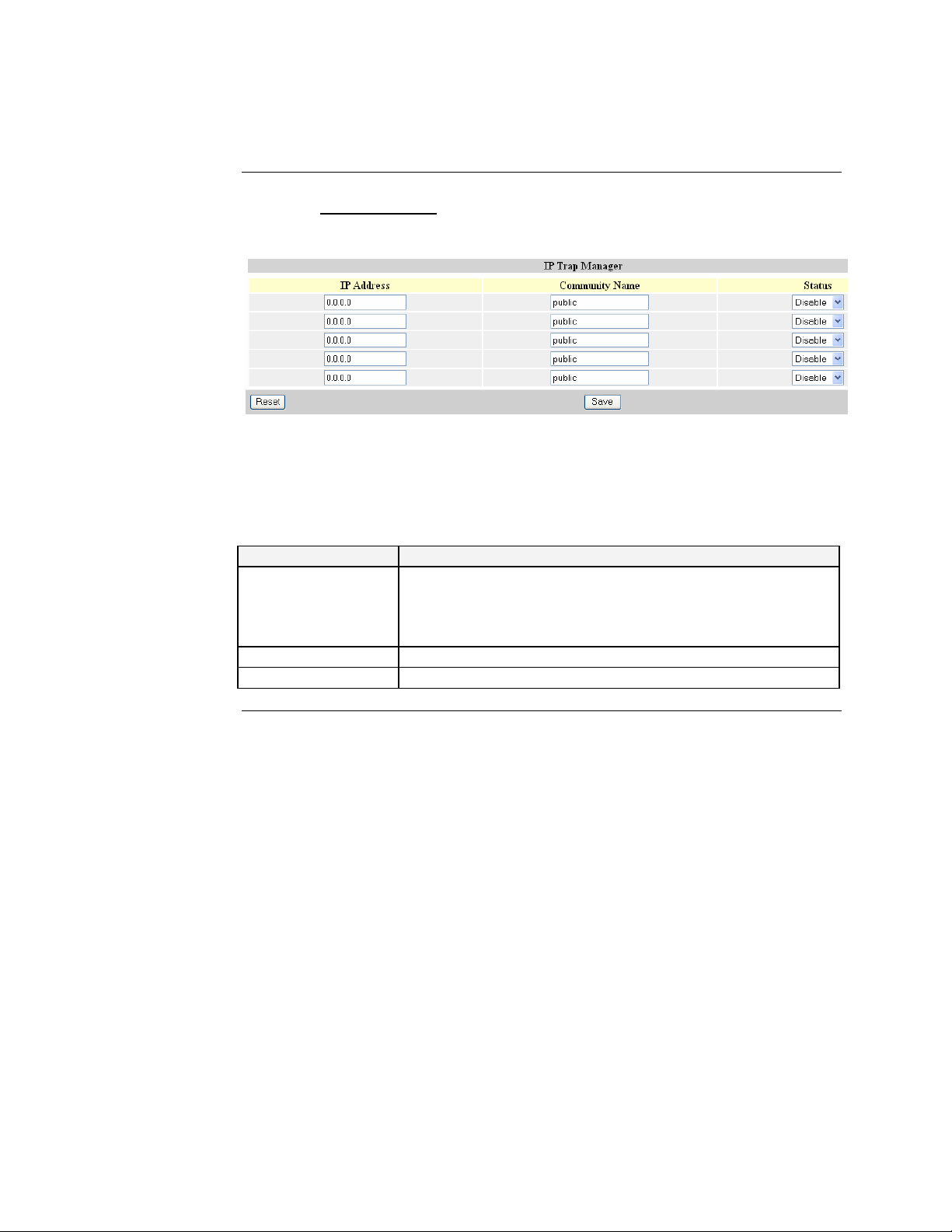
Click the “IP Trap Manager
shown in Figure 40.
Figure 40: IP Trap Manager Option display
” link to launch the IP Trap manager submenu option,
Table 2 describes the fields on the IP Trap Manager display.
Table 2: IP Trap Parameters and Descriptions
Parameter Description
IP Address Enter the IP address(s) of the terminal(s) that you want to
monitor for failures. When a failure occurs, an alarm will be
sent if enabled. Enter their community names and disable or
enable their alarm function accordingly.
Community Name SNMP community names.
Status Alarm function: disabled or enabled.
Continued on next page
24-Hour Technical Support: 1-800-260-1312 International: 00-1-952-941-7600
39
Page 52

Transition Networks SDSFE31xx-100 Industrial Device Server
Configuration software, continued
IP trap manager submenu (continued)
You can configure up to five management stations to receive authentication failure
messages or other trap messages from the Device Server.
To assign the IP Traps, do the following:
Step Action
1. Click the “IP address” parameter field. See Figure 41.
2. Type or paste the IP address in the field.
3. Click the “community name” parameter field. See Figure 41.
4. Type a name in the field.
5. Select status (enabled or disabled).
6. Click the SAVE button to save and establish the trap.
Note: Click the RESET button to reestablish the original parameter(s) before
saving changes.
40
Figure 41: Sample Configured IP Trap Manager Display
Continued on next page
24-Hour Technical Support: 1-800-260-1312 International: 00-1-952-941-7600
Page 53
SDSFE31xx-100 Industrial Device Server Transition Networks
Configuration software, continued
System restore
submenu
Click the System Restart
• System Restore
• Reset
link to show the Restart submenu options:
Note: You can “restore” or “reset” the Device Server remotely via software.
System restore
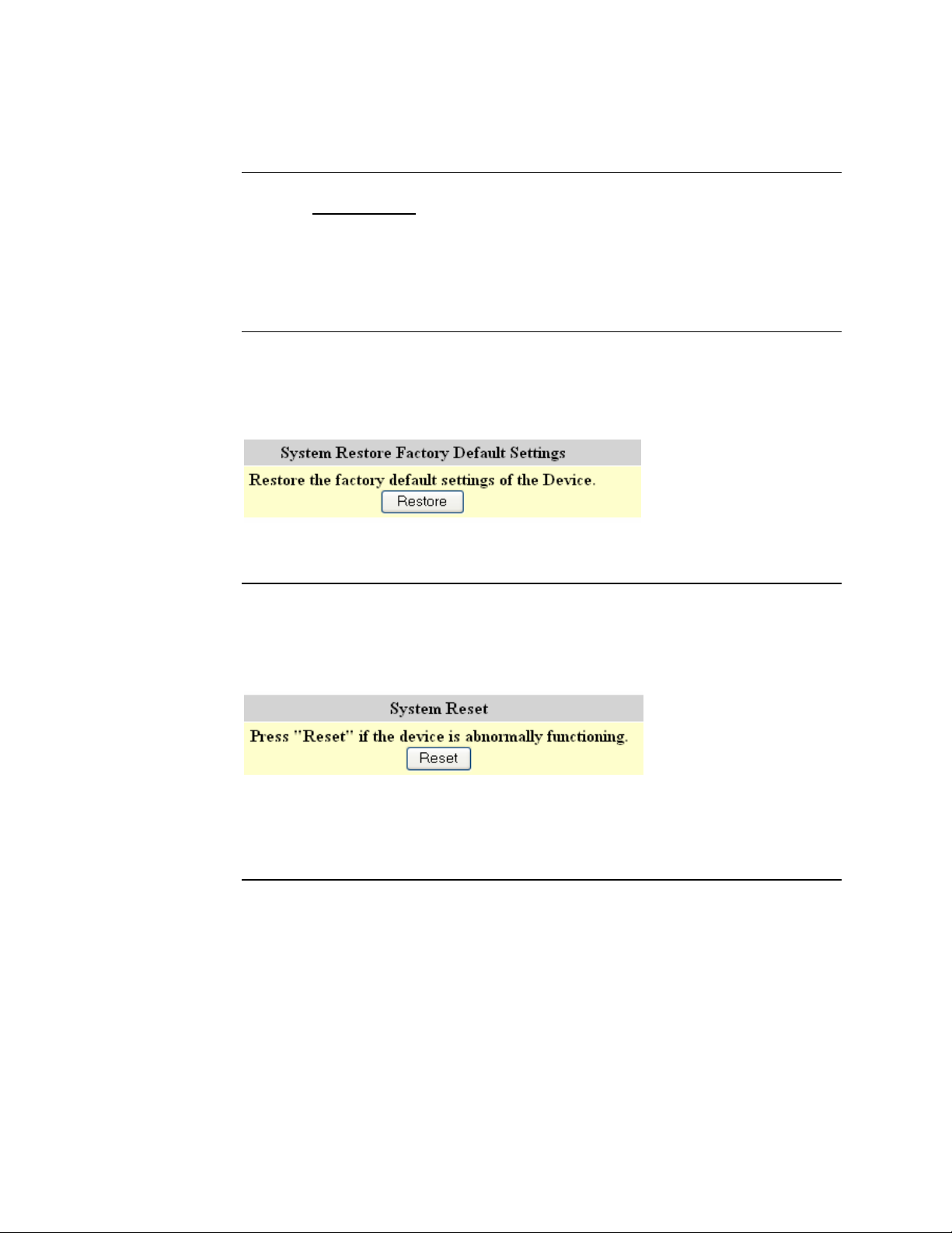
Click the RESTORE button, shown in Figure 42, to set the Device Server back to
factory defaults. After the timeout display disappears all saved configuration data
will be erased.
System reset
Figure 42: System Restore Button
Click the RESET button, shown in Figure 43, to reset the Device Server. After the
timeout disappears the system will be reset, but all configuration data will be
maintained (IP address, etc.).
Figure 43 System Reset Button
Note: System Reset has the same functionality as power cycling the Device Server.
24-Hour Technical Support: 1-800-260-1312 International: 00-1-952-941-7600
41
Page 54

Transition Networks SDSFE31xx-100 Industrial Device Server
Intentionally Blank
42
24-Hour Technical Support: 1-800-260-1312 International: 00-1-952-941-7600
Page 55

In the section
Section IV
Serial IP Redirector Software
This are the topics:
Topic See Page
Serial IP redirector software description 44
Getting started and software pre-installation considerations 45
Installing IP redirector software 46
Upgrading the software 50
Creating virtual COM ports 51
Page 56

Transition Networks SDSFE31xx-100 Industrial Device Server
Serial IP redirect software description
COM port
usage
Operating
environment
Configuration
wizard
The Serial/IP Redirector Software adds "virtual" COM ports to Windows operating
systems. Similar to regular COM ports that allow PC applications to use local serial
ports, Serial/IP COM ports allow PC applications to use the serial port on the Device
Server. Because Serial/IP COM ports work like regular COM ports, PC applications
do not have to be changed to use the Device Server through the Serial/IP Redirector.
The Serial/IP Redirector software runs as a kernel-level device driver in the
Windows operating system. This means that Serial/IP COM ports are available to PC
applications at all times, even if no user is logged in. The Serial/IP Redirector is a
high-performance kernel-mode driver with a small “footprint,” modest memory
requirements and low overhead. The Serial/IP applet in the Windows control panel
configures Serial/IP COM ports and displays their activity.
The Serial/IP Redirector software detects and uses the specific protocol supported by
the Device Server. When configuring Serial/IP COM port, use the Serial/IP
Configuration Wizard to verify immediately that the Serial/IP Redirector can
communicate with the Device Server over the network.
Networked
device server
The networked pieces fit together in the following manner:
Stage Description
A. Install the Device Server on the network and connect a device to its serial
port.
B. Configure the Device Server so that its serial port is available to the
network via TCP/IP.
C. Install the Serial/IP Redirector software on the PC that will use the device
attached to the Device Server.
D. Configure the Serial/IP Redirector software to create a virtual COM port.
E. Specify the IP address of a Device Server and the TCP port number that
provides access to its serial port.
F. In the PC application, change settings to use the Serial/IP COM port
instead of the local COM port.
G. Thereafter, the PC application can use the serial port on the Device Server
instead of local serial ports.
44
24-Hour Technical Support: 1-800-260-1312 International: 00-1-952-941-7600
Page 57

SDSFE31xx-100 Industrial Device Server Transition Networks
Getting started and software pre-installations considerations
Pre-installation
considerations
Supported platforms:
• Intel-compatible PCs with 32-bit Pentium-class processor
• At least 4 megabytes free space on the boot drive
• Windows XP sp1 or sp2, Server 2003, 2000, NT 4.0 sp6, 98/95/Me, Microsoft
.NT/2000/2003 Terminal Server, Citrix MetaFrame Access Suite
• VMware
Software requirements:
• Windows Installer 2.0 or later: This software is included in Windows XP and
later, and is available for NT 4.0, 2000 and 95 from the Microsoft Download
Center. It is also available for Windows 98 in Internet Explorer 5.5
• Internet Explorer 4.0 or later (version 5.5 or later for Windows 98)
• For Windows 95: Microsoft Windows Socket 2 update
What is
needed?
Network requirements:
• A TCP/IP network connection from the local computer to the serial Device
Server.
• The throughput and performance of the network connection must exceed the
requirements of the application in total. (An Ethernet local area network will
easily meet this requirement.)
• If firewalls are in the network path to the serial Device Server, they must allow
TCP connections to the server on the TCP port number(s) on which the server
provides its devices. If used, this includes Windows XP service-pack 2 firewall.
Before installing the Serial/IP Redirector software, do the following:
Step Action
1. Obtain administrator privileges before installing the software.
2. Install the Device Server on the TCP/IP local area network.
3. Configure the Device Server to provide its serial port to the network,
4. Follow the general guidance about Device Server configuration in this
manual. Also, see the latest “help files” the Serial/IP Redirector software
by clicking the HELP button on the Serial/IP Control Panel dialog box.
5. Install the software on the PC that will use the serial port.
24-Hour Technical Support: 1-800-260-1312 International: 00-1-952-941-7600
45
Page 58

Transition Networks SDSFE31xx-100 Industrial Device Server
Installing serial IP redirector software
Software
installation
To install the software, do the following:
Step Action
1. Login as a user with administrator privileges.
2. Quit all Windows programs using COM ports.
3. Install the Serial/IP Redirector Software CD into the PC/Laptop that will
be in communication with the serial port of the Device Server to launch
the “installation wizard” dialog box, shown in Figure 44.
Figure 44: Installation Wizard Dialog Box
4. If the install wizard dialog box does not appear, at the command line
type: Serial IP Redrector432.exe and then press the ENTER key.
5. Press the NEXT button and a “license agreement” dialog box will
appear, as shown in Figure 45.
Figure 45: Agreement Dialog Box
46
Continued on next page
24-Hour Technical Support: 1-800-260-1312 International: 00-1-952-941-7600
Page 59

SDSFE31xx-100 Industrial Device Server Transition Networks
Installing serial IP redirector software, continued
Step Action
6. Click the AGREE radio button.
7. Click the NEXT button and the “destination folder” will appear as
shown in Figure 46.
Figure 46: Software Destination Folder Dialog Box
8. If the destination folder in the dialog box is not where you want the
software to load, click the BROWSE button, and then select a new
location.
9. Click the NEXT button and the “select features” dialog box will appear,
as shown in Figure 47.
Continued on next page
24-Hour Technical Support: 1-800-260-1312 International: 00-1-952-941-7600
47
Page 60

Transition Networks SDSFE31xx-100 Industrial Device Server
Installing serial IP redirector software, continued
Figure 47: Select Features Dialog Box
On the select features dialog box, you can select how much of the software you want
to load on the PC/Laptop (disk space consideration) via the pulldown menu. See
Figure 48.
Figure 48: Pulldown Menu Options
Note: The “administrator only” option restricts use of the Serial/IP Control Panel to
users with administrator privileges. If you select this option, nonadministrator users can use the Serial/IP Redirector, but they cannot open the
Serial/IP Control Panel.
Step Action
10. Click the NEXT button on the select features dialog box to launch the
“ready to install software” dialog box, shown in Figure 49.
Continued on next page
48
24-Hour Technical Support: 1-800-260-1312 International: 00-1-952-941-7600
Page 61

SDSFE31xx-100 Industrial Device Server Transition Networks
Installing serial IP redirector software, continued
Figure 49: Ready to Install Application Dialog Box
Step Action
11. Click the view release notes check box, if not selected.
12. Click the NEXT button to install the software. When completed, the
“successfully installed” message box will appear, as shown in Figure 50.
Figure 50: Install Successful Message Box
13. Click the FINISH button and the “release notes” will appear on the
screen.
14. Close the “release notes” and the Serial IP Control Panel will appear.
24-Hour Technical Support: 1-800-260-1312 International: 00-1-952-941-7600
49
Page 62

Transition Networks SDSFE31xx-100 Industrial Device Server
Upgrading serial IP redirector software
Software
upgrades
If you are installing a software upgrades, please note:
• The existing software must be the same major version (version 4).
• The setup program will remove the existing Serial/IP software.
• The virtual COM port selections and settings will be maintained.
When upgrading the software, you will be prompted to uninstall the old version of
the software, as shown in Figure 51.
Figure 51: Uninstall Message Box
IMPORTANT
Excluding Windows XP, in all other Windows environments you must “restart” the
computer to finish uninstalling the software before installing the upgrade. Not
restarting the computer could result in an error during the software upgrade.
Step Action
1. Click the YES button to uninstall the software; when successful the
“installation wizard will appear, shown in Figure 52.
2. Restart the computer, if necessary, before installing the upgrade.
50
Figure 52: Installation Wizard
24-Hour Technical Support: 1-800-260-1312 International: 00-1-952-941-7600
Page 63

SDSFE31xx-100 Industrial Device Server Transition Networks
Creating virtual COM ports
Control panel
After loading the software, the Serial IP Control Panel dialog box will appear, as
shown in Figure 53.
Figure 53: Serial IP Control Panel Dialog Box
Use the “control panel” to configure virtual COM ports and advanced options.
Note: If the Serial/IP Redirector has been installed with the Administrator-Only
Mode feature, the Serial/IP control panel will be available only to users with
Administrator privileges. Changed settings do not affect the operation of
currently active virtual COM ports.
24-Hour Technical Support: 1-800-260-1312 International: 00-1-952-941-7600
Continued on next page
51
Page 64

Transition Networks SDSFE31xx-100 Industrial Device Server
Creating virtual COM ports, continued
Virtual COM
port creation
Alternatively, you can edit the COM port ranges directly. Use individual COM port
numbers (such as 4, 5, 7) and/or ranges of numbers (such as 11-18, 30-53) separated
by commas. As you edit the COM port ranges, checkboxes in the upper panel will
change accordingly. (Invalid numbers or ranges will be displayed.)
COM Port
configuration
To configure virtual COM ports, do the following:
Step Action
1.
On the control panel, click the SELECT PORTS button to bring up
the “select ports” dialog box shown in Figure 54.
52
Figure 54: Select Ports Dialog Box
Note: You can select up to 4,096 virtual COM ports. COM1 and COM2 are
normally physical ports, so they will not appear in the dialog box.
2. Select a virtual COM port from the list (COM7 in this example). The
COM port selection will appear in the lower panel of the select port
dialog box.
3. Click the OK button to establish COM port 7.
Continued on next page
24-Hour Technical Support: 1-800-260-1312 International: 00-1-952-941-7600
Page 65
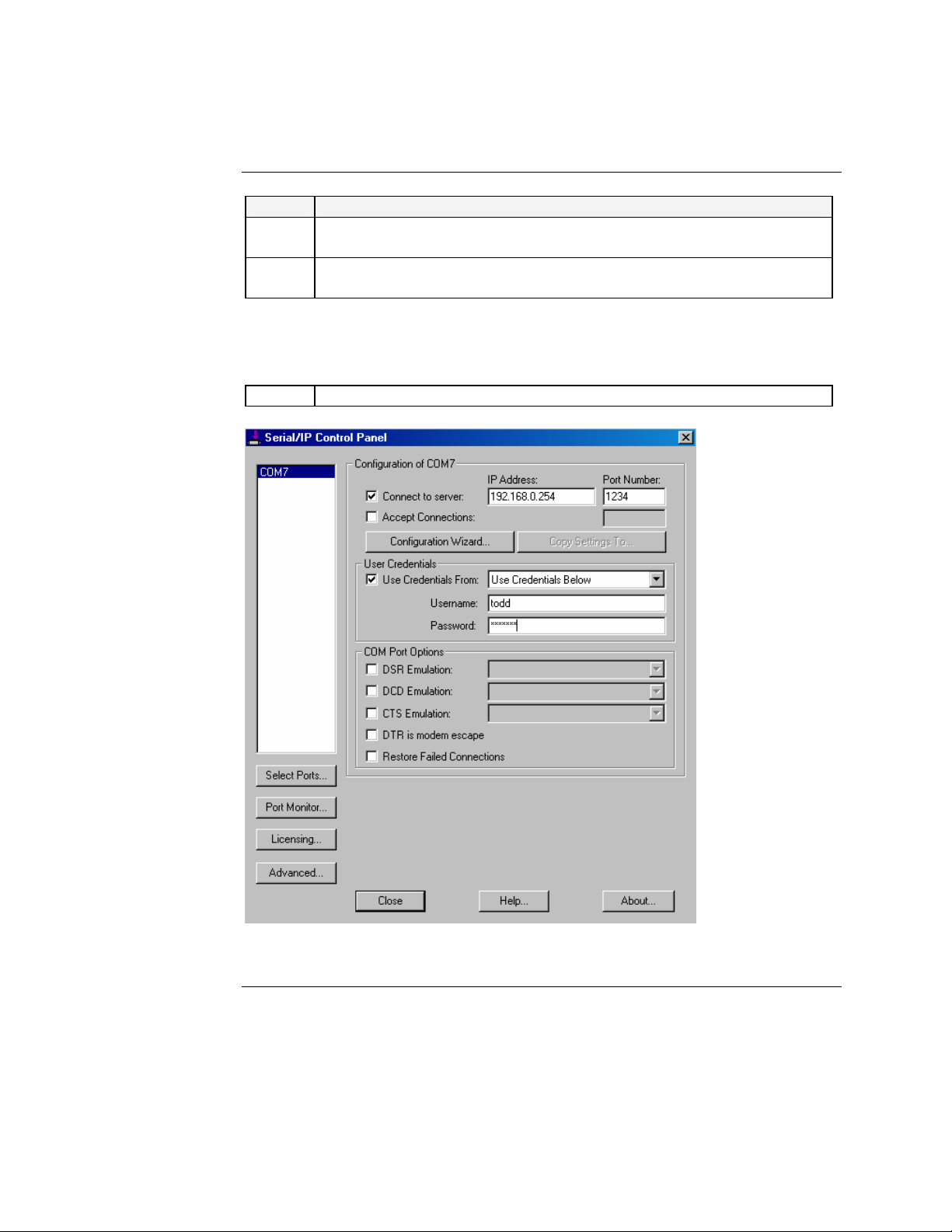
SDSFE31xx-100 Industrial Device Server Transition Networks
Creating virtual COM ports, continued
Step Action
4. On the Serial IP Control Panel, enter the IP address and port number of
the Device Server. See Figure 55.
5. Check “user credentials” and select “use credentials below” from the
pulldown menu. See Figure 55.
Note: If a user name and password were set when setting up the Device Server, use
that same user name and password here.
6. Enter a “user name” and “password” if previously set. See Figure 55.
Figure 55: Virtual Port Configuration
24-Hour Technical Support: 1-800-260-1312 International: 00-1-952-941-7600
Continued on next page
53
Page 66

Transition Networks SDSFE31xx-100 Industrial Device Server
Creating virtual COM ports, continued
Step Action
7. Click the CONFIGURATION WIZARD button to bring up the
“configuration wizard,” shown in Figure 56.
54
Figure 56: COM Port 7 Configuration Wizard
8. If any of the settings are incorrect, change them.
9. Click the START button. Note as the wizard runs, the “status panel” will
show a summary of server characteristics. The “log panel” shows the
wizard’s interaction with the server. The wizard typically takes 5 to 15
seconds to complete its task.
Continued on next page
24-Hour Technical Support: 1-800-260-1312 International: 00-1-952-941-7600
Page 67

SDSFE31xx-100 Industrial Device Server Transition Networks
Creating virtual COM ports, continued
If the wizard
fails
The wizard indicates errors in the status panel, with error details appearing in the log
panel. In the case of an error, do the following before re-running the wizard:
Step Action
1. Review error messages in the status panel. See Figure 57.
2. If necessary, review the messages in the log panel. See Figure 57.
3. Correct the wizard settings.
4. Restart the wizard with the corrected settings.
If the wizard is
successful
The wizard indicates a successful run by messages in the status panel; also, the USE
SETTING button will be active. See Figure 57.
Figure 57: COM Port Configuration Wizard
24-Hour Technical Support: 1-800-260-1312 International: 00-1-952-941-7600
Continued on next page
55
Page 68
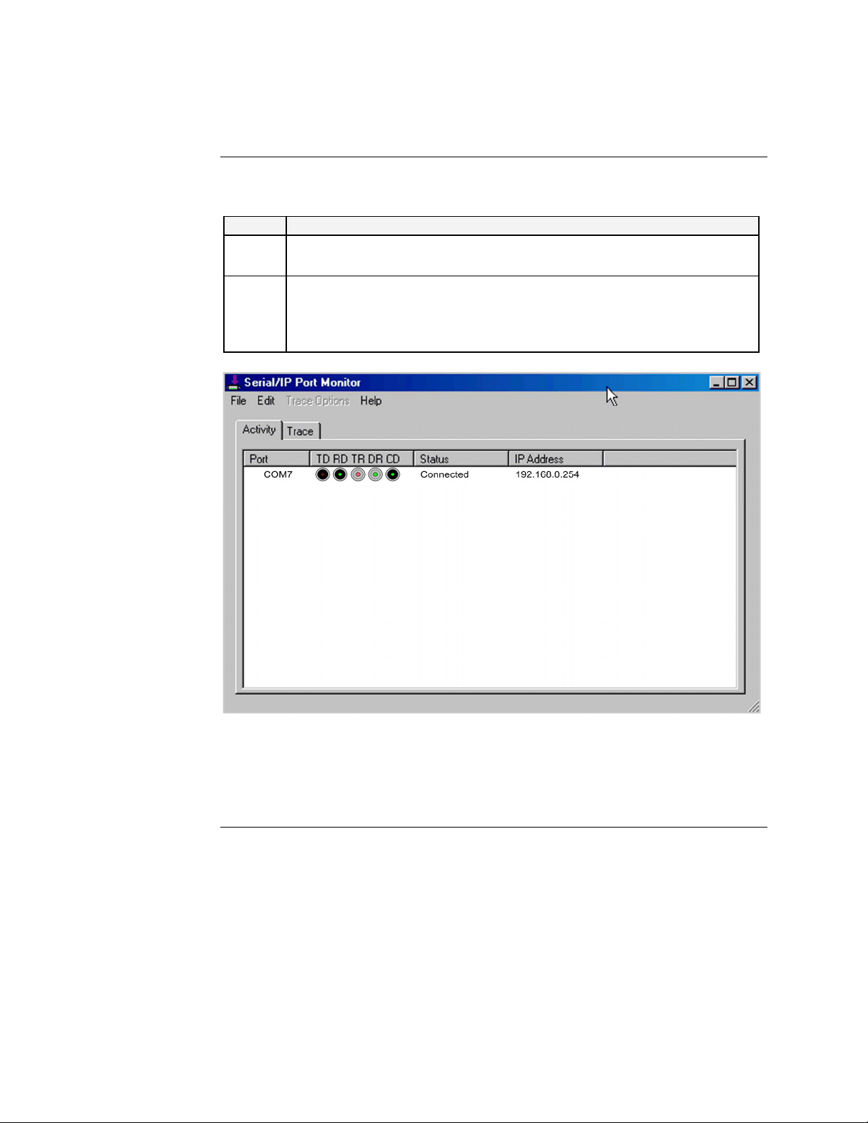
Transition Networks SDSFE31xx-100 Industrial Device Server
Creating virtual COM ports, continued
If the wizard is successful (continued)
Step Action
5. Click the USER SETTING button on the wizard to return to the control
panel.
6. Once the link is established, you can manage the device attached to the
Device Server, using the Serial IP Redirector software installed on a
remote computer. Click the PORT MONITOR button on the control
panel to bring up the port monitor, shown in Figure 58.
56
Figure 58: Serial/IP Port Monitor
Note: If more devices are attached and connected, the status and IP address of
those devices will appear against each Virtual COM port listed.
24-Hour Technical Support: 1-800-260-1312 International: 00-1-952-941-7600
Page 69

Introduction
In this section
Section V:
Troubleshooting
This section provides basic troubleshooting information for the Device Server via a
problem and corrective action table. The problems are stated in the problem column
and the action(s) to take for the problem is stated in the corrective action column. If
the corrective measures listed do not correct the problem, contact our 24-Hour
Technical Support department at 1-800-260-1312, International: 00-1-952-941-7600.
These are the topics:
Topic See Page
Troubleshooting problem and corrective action table 58
Page 70

Transition Networks SDSFE31xx-100 Industrial Device Server
Troubleshooting problem and corrective action table
Problem Potential Cause Potential Solution
Device Server does not
power up
No activity at the DB-9
port
No activity on the fiber
port
• Is the wired terminal-block plug
inserted into the Device Server?
• Is the power LED lit?
• Is the power LED lit?
• Can the Device Server receive
link pulses?
• Is the DB-9 cable properly
installed at both ends?
• Is the DB-9 cable good?
• Is the LNK/ACT LED lit
(green)?
• Wire and insert the terminal-block
plug into the Device Server’s
terminal block
• Check that DC power is at the
recommended levels.
• Contact Technical Support.
US/Canada: 1-800-260-1312,
International: 00-1-952-941-7600
• Check the power is turned ON.
• Send link pass from the connected
device (if a computer, press any key
and the Device Server’s ACT LED
will flicker each time you press the
key.)
• Verify that the cable at both ends is
installed properly
• Check pin assignments
• Contact Technical Support.
US/Canada: 1-800-260-1312,
International: 00-1-952-941-7600
• Ensure that the fiber optic cable is
installed properly into the Device
Server and the compliant device
• Power up the compliant connected
device.
• Contact Technical Support.
US/Canada: 1-800-260-1312,
International: 00-1-952-941-7600
58
24-Hour Technical Support: 1-800-260-1312 International: 00-1-952-941-7600
Page 71

Introduction
In this section
Section VI:
Cable Specifications
This section provides copper and fiber cable specifications.
These are the topics:
Topic See Page
DB-9 (RS-232) serial cable specifications 60
Fiber cable and optic specifications 61
Page 72
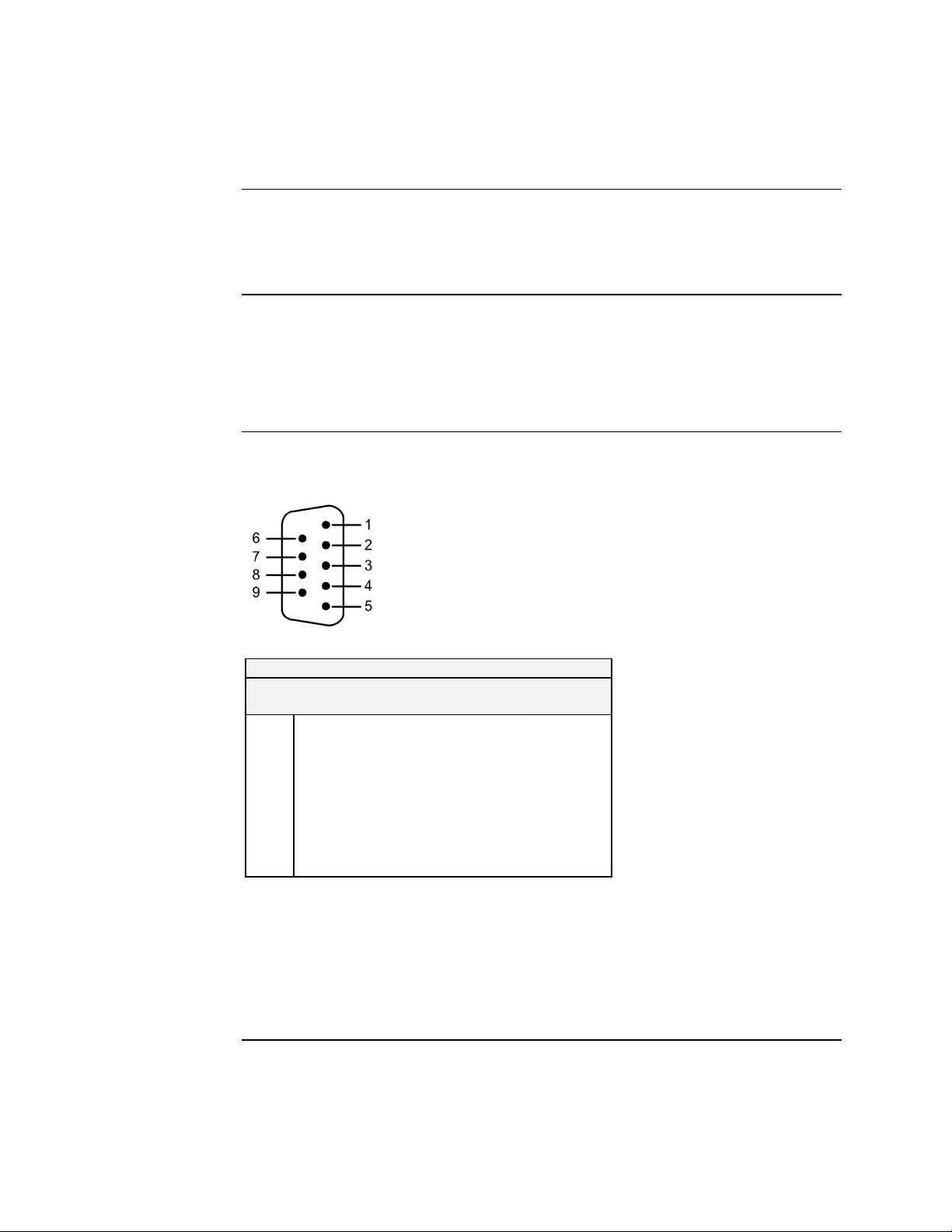
Transition Networks SDSFE31xx-100 Industrial Device Server
Copper DB-9 (RS-232) serial cable specifications
What is RS-232
(DB-9)?
DB-9 cable
specifications
DB-9 cable
pinouts
RS-232 is a serial device control protocol that provides an interface between Data
Terminal Equipment (DTE) and Data Communications Equipment (DCE) that
employs serial binary data interchanges.
Wire category: 3 to 5
Maximum data rate: 100Kb/s, 115.2Kb/s asynchronous (distance dependent)
Gauge: 24 to 22 AWG
Maximum cable distance: 50 ft (15.24 m)
Figure 59 shows the DB-9 (RS-232) serial cable pin assignments and pinout chart.
DB-9 Connector Pin Assignments
No Code Description
1 DCD Data Carrier Detect IN
2 RX Receive Data IN
3 TX Transmit Data OUT
4 DTR Data Terminal Ready OUT
5 GND Ground —
6 DSR Data Set Ready IN
7 RTS Request to Send OUT
8 CTS Clear to Send IN
9 RI Ring Indicator IN
Signal
Direction
Figure 59: DB-9 Connector and Cable Pin Assignment Chart
Note: The Device Server is configured as a DTE device. Use a straight-through
cable for connecting to a DCE device, or a crossover cable for connecting to
other DTE devices.
60
24-Hour Technical Support: 1-800-260-1312 International: 00-1-952-941-7600
Page 73

SDSFE31xx-100 Industrial Device Server Transition Networks
Fiber cable and optic specifications
Fiber cable
characteristics
Fiber optic
specifications
Cable physical characteristics must meet or exceed IEEE 802.3™ specifications.
Parameter Specification
Bit Error Rate: <10-9
Single mode fiber: 9 µm
Multimode fiber: 62.5/125 µm
Multimode fiber: 100/140, 85/140, 50/125 µm
The following shows the fiber optic specification:
Fiber Cable Specifications
SDSFE3111-100
Fiber-optic transmitter power:
Fiber-optic receiver sensitivity:
Link budget:
SDSFE3113-100
Fiber-optic transmitter power:
Fiber-optic receiver sensitivity:
Link budget:
SDSFE3114-100
Fiber-optic transmitter power:
Fiber-optic receiver sensitivity:
Link budget:
SDSFE3115-100
Fiber-optic transmitter power:
Fiber-optic receiver sensitivity:
Link budget:
SDSFE3117-100
Fiber-optic transmitter power:
Fiber-optic receiver sensitivity:
Link budget:
1300 nm multimode
min: -19.0 dBm max: -14.0 dBm
min: -31.0 dBm max: -4.0 dBm
12.0dB
1300 nm multimode
min: -19.0 dBm max: -14.0 dBm
min: -31.0 dBm max: -4.0 dBm
12.0dB
1310 nm single mode
min: -15.0 dBm max: -3.0 dBm
min: -30.0 dBm max: -3.0 dBm
15.0 dB
1310 nm single mode
min: -15.0 dBm max: -8.0 dBm
min: -34.0 dBm max: -7.0 dBm
19.0 dB
1550 nm single mode
min: -3.0 dBm max: 3.0 dBm
min: -37.0 dBm max: 0.0 dBm
34.0 dB
24-Hour Technical Support: 1-800-260-1312 International: 00-1-952-941-7600
61
Page 74

Transition Networks SDSFE31xx-100 Industrial Device Server
Intentionally Blank
62
24-Hour Technical Support: 1-800-260-1312 International: 00-1-952-941-7600
Page 75

Introduction
In this section
Section VII:
Contact Us, Warranty, &
Conformity Information
This section explains how to contact Transition Networks via Phone, fax, email, and
direct mail. It also explains:
• What the warranty covers
• Who to contact to return product
• How and where to return the product
These are the topics:
Topic See Page
Contact us 64
Conformity declaration 65
Warranty 66
Compliance information 68
Page 76

Transition Networks SDSFE31xx-100 Industrial Device Server
Contact us
Technical
support
Live Web chat
Web-based
training
E-Mail
Technical Support is available 24 hours a day.
United States: 1-800-260-1312
International: 00-1-952-941-7600
Chat live via the Web with a Transition Networks Technical Support Specialist.
Log onto www.transition.com and click the Transition Now link.
Transition Networks provides 12-16 seminars per month via live web-based training.
Log onto www.transition.com and click the Learning Center link.
Ask a question anytime by sending an e-mail message to our technical support staff
@ techsupport@transition.com
Address
Transition Networks
6475 City West Parkway
Minneapolis, MN 55344, U.S.A.
Telephone: 952-941-7600
Toll free U.S.A & Canada: 800-526-9267
Fax: 952-941-2322
64
24-Hour Technical Support: 1-800-260-1312 International: 00-1-952-941-7600
Page 77

SDSFE31xx-100 Industrial Device Server Transition Networks
Conformity declaration
Declaration of Conformity
Name of Mfg: Transitions Networks
6427 City West Parkway, Minneapolis MN 55344 U.S.A.
Model: SDSFE31xx-100 Industrial
Part Numbers: SDSFE3111-100, SDSFE3113-100, SDSFE3114-100,
Regulations: EMC Directive 89/336/EEC
Purpose: To declare that the SDSFE31xx-100 Industrial Device Servers to which this
CISPR22:1993; EN55022:1994+A1:1995+A2:1997 Class A; FCC Part 15
I, the undersigned, hereby declare that the equipment specified above conforms to the above
Directive(s) and Standard(s).
Steven Anderson, Vice President of Engineering Date
declaration refers is in conformance with the following standards:
Subpart B; UL1950; 21 CFR Subpart J
Device Server
SDSFE3115-100, SDSFE3117-100
September, 2006
24-Hour Technical Support: 1-800-260-1312 International: 00-1-952-941-7600
65
Page 78

Transition Networks SDSFE31xx-100 Industrial Device Server
Warranty
Limited lifetime
warranty
What the
warranty does
not cover
Establishing
original
ownership
Effective for products shipped May 1, 1999 and After. Every Transition Networks’
labeled product purchased after May 1, 1999 will be free from defects in material
and workmanship for its lifetime. This warranty covers the original user only and is
not transferable.
This warranty does not cover damage from accident, acts of God, neglect,
contamination, misuse or abnormal conditions of operation or handling, including
over-voltage failures caused by use outside the product’s specified rating, or normal
wear and tear of mechanical components. If the user is unsure of the proper means of
installing or using the equipment, contact Transition Networks’ free technical
support services.
To establish original ownership and provide date of purchase, please complete and
return the registration card accompanying the product or register the product on-line
on our product registration page.
Transition Networks will at its option:
Who to contact
for returns
• Repair the defective product to functional specification at no charge
• Replace the product with an equivalent functional product
• Refund the purchase price of a defective product
To return a defective product for warranty coverage, contact Transition Networks’
technical support department for a return authorization number (RAN). Transition’s
technical support department can be reached through any of the following means:
Technical Support is available 24 hours a day:
• Tel: 800-260-1312 x 200 or 952-941-7600 x 200
• Fax: 952-941-2322
• Email: techsupport@transition.com
• Live web chat: Transition Now
• Voicemail: 800-260-1312 x 579 or 952-941-7600 x 579
• All messages will be answered within one hour
Continued on next page
66
24-Hour Technical Support: 1-800-260-1312 International: 00-1-952-941-7600
Page 79

SDSFE31xx-100 Industrial Device Server Transition Networks
Warranty, continued
How and where
to send the
returns
Send the defective product postage and insurance prepaid to the following address:
CSI Material Management Center
c/o Transition Networks
6103 Blue Circle Drive
Minnetonka, MN 55343 U.S.A.
Attn: RETURNS DEPT: Credit Return Authorization (CRA)# or Return Material
Authorization (RMA) # ___________
Failure to protect the product during shipping may void this warranty. The return
authorization number must be written on the outside of the carton to ensure its
acceptance. We cannot accept delivery of any equipment sent to us without a CRA or
RMA number.
Customer pays
non-compliant
return costs
The customer must pay the non-compliant product(s) return transportation cost to
Transition Networks for evaluation of said product(s) for repair or replacement.
Transition Networks will pay for shipping the repaired or replaced in-warranty
product(s) back to the customer (any and all customs charges, tariffs, or/and taxes
are the customer’s responsibility).
Non-warranty
repair costs
Repaired nonwarranty
products
This warranty
is your only
remedy
Before making any non-warranty repair, Transition Networks requires a $200
charge, plus actual shipping costs to and from the customer. If the repair is greater
than $200, an estimate is issued to the customer for authorization of repair. If no
authorization is obtained, or the product is deemed not repairable, Transition
Networks will retain the $200 service charge and return the product to the customer
not repaired.
Non-warranted products repaired by Transition Networks for a fee will carry a 180day limited warranty. All warranty claims are subject to the restrictions and
conventions set forth by this document.
Transition Networks reserves the right to charge for all testing and shipping incurred,
if after testing, a return is classified as “No Problem Found.”
This warranty is your only remedy. No other warranties, such as fitness for a
particular purpose, are expressed or implied. Transition Networks is not liable for
any special, indirect, incidental or consequential damages or losses, including loss of
data, arising from any cause or theory. Authorized resellers are not authorized to
extend any different warranty on transition networks’ behalf.
24-Hour Technical Support: 1-800-260-1312 International: 00-1-952-941-7600
67
Page 80

Transition Networks SDSFE31xx-100 Industrial Device Server
Compliance information
Compliances
FCC
Regulations
Canadian
Regulations
CISPR22/EN5022 Class A + EN55024; EN60950 Class A; FCC Class A; CE Mark
This equipment has been tested and found to comply with the limits for a Class A
digital device, pursuant to part 15 of the FCC rules. These limits are designed to
provide reasonable protection against harmful interference when the equipment is
operated in a commercial environment. This equipment generates, uses, and can
radiate radio frequency energy and, if not installed and used in accordance with the
instruction manual, may cause harmful interference to radio communications.
Operation of this equipment in a residential area is likely to cause harmful
interference, in which case the user will be required to correct the interference at the
user’s own expense.
This digital apparatus does not exceed the Class A limits for radio noise for digital
apparatus set out on the radio interference regulations of the Canadian Department of
Communications. Le présent appareil numérique n'émet pas de bruits
radioélectriques dépassant les limites applicables aux appareils numériques de la
Class A prescrites dans le Règlement sur le brouillage radioélectrique édicté par le
ministère des Communications du Canada.
European
Regulations
CUATION:
This is a Class A product. In a domestic environment, this product could cause radio
interference in which case the user may be required to take adequate corrective
measures.
Achtung !
Dieses ist ein Gerät der Funkstörgrenzwertklasse A. In Wohnbereichen können bei
Betrieb dieses Gerätes Rundfunkstörungen auftreten. In diesem Fäll ist der Benutzer
für Gegenmaßnahmen verantwortlich.
Attention !
Ceci est un produit de Classe A. Dans un environment domestique, ce produit risque
de créer des interférences radioélectriques, il appartiendra alors à l'utilsateur de
prende les measures spécifiques appropriées.
Continued on next page
68
24-Hour Technical Support: 1-800-260-1312 International: 00-1-952-941-7600
Page 81

SDSFE31xx-100 Industrial Device Server Transition Networks
Compliance information, continued
European
Regulations,
(continued)
Der Anschluss dieses Gerätes an ein öffentlickes Telekommunikationsnetz in den
EG-Mitgliedstaaten verstösst gegen die jeweligen einzelstaatlichen Gesetze zur
Anwendung der Richtlinie 91/263/EWG zur Angleichung der Rechtsvorschriften der
Mitgliedstaaten über Telekommunikationsendeinrichtungen einschliesslich der
gegenseitigen Anerkennung ihrer Konformität.
In accordance with European Union Directive 2002/96/EC of the
European Parliament and of the Council of 27 January 2003, Transition
Networks will accept post usage returns of this product for proper disposal.
The contact information for this activity can be found in the ‘Contact Us’
portion of this document.
CAUTION: RJ connectors are NOT INTENDED FOR CONNECTION
TO THE PUBLIC TELEPHONE NETWORK. Failure to observe this
caution could result in damage to the public telephone network.
24-Hour Technical Support: 1-800-260-1312 International: 00-1-952-941-7600
69
Page 82

Transition Networks SDSFE31xx-100 Industrial Device Server
Intentionally Blank
70
24-Hour Technical Support: 1-800-260-1312 International: 00-1-952-941-7600
Page 83
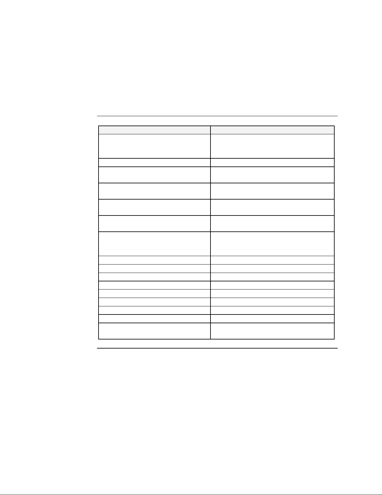
Appendix A:
Technical Specification
SDSFES31xx-100 specifications, notices, and warnings
Parameter Description
Standards IEEE 802.3 (100BASE-FX/ Fast Ethernet)
EIA/TIA RS-232
EIA/TIA-574
Regulatory Compliance for Emission FCC Part 15 of Class A & CE approved
Ports 1x fiber single mode/multi-mode
1x 9-pin serial connector; D-sub, male
Max Distance Fiber: up to 120,000 meters (74.5 miles)
Serial: up to 15 meters (50 ft.)
Max Data Rate Fiber: 100 Mbs
Serial: 115.2 Kbps (asynchronous)
Signals TxD, RxD, CTS, RTS, DTR, DSR, RI,
DCD, GND
Safety Compliance CISPR22/EN5022 Class A + EN55024;
EN60950 Class A; FCC Class A and CE
Mark
Power Consumption 3.4 watts
Ingress Protection IP30
MTBF 123,778
Power Source External, 9 to 48VDC @ 1A
Size (width x depth x height) 2 x 3.9 x 4.7 in (50 x 100 x120mm)
Weight 0.90 kg (2 lbs)
Operating Temperature 0 to 70ºC (32 to 158ºF)
Storage Temperature -20 to 80º C (-4 to 176ºF)
Operating Humidity 5% to 90% (non-condensing), altitude 0-
10,000 ft
Continued on next page
Page 84
Transition Networks SDSFE31xx-100 Industrial Device Server
SDSFES31xx-100 specifications, notices, and warnings, continued
Notices
• The information in this user’s guide is subject to change. For the most up-to-date
information on the SDSFE31XX-100 Industrial Device Server, the user’s guide
on-line at: www.transition.com.
• Product is certified by the manufacturer to comply with DHHS Rule 21/CFR,
Subchapter J applicable at the date of manufacture.
• IMPORTANT Copper based media ports: e.g., Twisted Pair (TP) Ethernet, USB,
RS-232, RS422, RS485, DS1, DS3, Video Coax, etc., are intended to be
connected to intra-building (inside plant) link segments that are not subject to
lightening transients or power faults. Copper based media ports: e.g., Twisted Pair
(TP) Ethernet, USB, RS-232, RS-422, RS-485, DS1, DS3, Video Coax, etc., are
NOT to be connected to inter-building (outside plant) link segments that are
subject to lightening transients or power faults. Failure to observe this caution
could result in damage to equipment.
Warnings
WARNING: Visible and invisible laser radiation when open: Do not stare into
the beam or view the beam directly with optical instruments. Failure to observe
this warning could result in an eye injury or blindness.
WARNING: Use of controls, adjustments or the performance of procedures
other than those specified herein may result in hazardous radiation exposure.
72
24-Hour Technical Support: 1-800-260-1312 International: 00-1-952-941-7600
Page 85

Index
Alarm
fault indications ......................................................... 16
Cabling
DB-9 cable types....................................................... 18
DB-9 to serial port................................................... 18
fiber ............................................................................. 17
Caution & Warnings
definitions................................................................... viii
COM Port
1 and 2 ........................................................................ 52
configuration.......................................... 52, 53, 54, 55
configuration wizard ................................................ 55
control panel ............................................................. 51
creating virtual........................................................... 52
if the wazard fails configuring................................. 55
monitor....................................................................... 56
number of................................................................... 52
selecting...................................................................... 52
usage............................................................................ 44
Configuration
COM port wizard..................................................... 55
expanded software tree.......................................... 25
how to backup ....................................................36, 37
IP address ................................................................... 35
IP trapes...................................................................... 39
SNMP communities.................................................. 38
system backup........................................................... 36
web access ................................................................. 23
Connection
idle time...................................................................... 28
RS-232 status............................................................. 30
Contact Us...................................................................... 64
DB-9
crossover/straight thru cable................................. 18
serial cable pinouts................................................... 60
Device Server
configuration.............................................................. 23
configured as DTE.................................................... 60
dip switches ............................................................... 19
features..........................................................................2
grounding.................................................................... 11
models............................................................................3
modes
converter (CR) and server (DS).........................28, 29
mounting to DIN rail ............................................... 10
number of ports managed .........................................2
operating voltage range.......................................2, 71
terminal block............................................................ 12
terminal block plug
alarm wiring................................................................... 15
power wiring.................................................................. 13
wiring recommendations ........................................ 11
DIN Rail
clip.................................................................................. 9
device server mounting ...........................................10
DIP Switches....................................................................19
Fiber
cable connection ....................................................... 17
cable physical characteristics..................................61
cable specifications....................................................61
optic specifications....................................................61
Firmware
download .................................................................... 32
HTTP upgrade ..............................................32, 33, 34
TFTP server upgrade......................................... 34, 35
version......................................................................... 26
Firmware Version........................................................... 26
Grounding
device server.............................................................. 11
GUI
hardware/firmware versions................................... 26
main menu..................................................................24
master info submenu................................................ 26
RS-232 connection status display
item descriptions...........................................................30
RS-232 transfer config display ................................ 27
serial port config submenu............................... 28, 29
software tree .............................................................25
system info submenu................................................ 26
user name/password display...................................31
Hardware Version.......................................................... 26
Installation
DB-9 cable..................................................................18
Device Server .............................................................. 8
device server to DIN rail .......................................... 9
DIN rail ......................................................................... 9
fiber cables..................................................................17
redirector software..................................................46
what to consider......................................................... 8
where to install? .......................................................... 8
IP Traps
how to configure....................................................... 40
manager....................................................................... 39
parameters and descriptions .................................. 39
LEDs
where located and descriptions............................. 22
Loging In
web access.................................................................. 23
Operation
configuration software.............................................25
LEDs
where located and descriptions ................................22
serial IP redirector software...................................44
web access configuration.........................................23
24-Hour Technical Support: 1-800-260-1312 International: 00-1-952-941-7600 73
Page 86

Transition Networks SDSFE31xx-100 Industrial Device Server
Packet Mode
input and timeout values......................................... 29
Parts/Functions............................................................. 4, 5
Power
how to wire............................................................... 13
primary/redundant.................................................... 12
terminal block............................................................ 12
terminal block location............................................ 12
terminal-block plug wiring...................................... 13
Redirector Software
config wizard.............................................................. 44
control panel ............................................................. 51
creating COM ports...........................................51, 52
how to upgrade......................................................... 50
importance notice .................................................... 50
installation.............................................. 46, 47, 48, 49
network requirements ............................................ 45
operating environment............................................ 44
pre-installation steps................................................ 45
requirements............................................................. 45
supported platforms ................................................ 45
Regulations
Canadian..................................................................... 68
European ..............................................................68, 69
FCC requlations........................................................ 68
Relay
how to wire............................................................... 15
Restore/Reset................................................................. 41
RS-232
cable connection....................................................... 18
cable pinouts .............................................................. 60
port connection status.............................................30
specification................................................................ 60
transfer configuration............................................... 27
what is ......................................................................... 60
Serial Tunneling...............................................................29
SNMP Communities
two community strings get and set.......................38
Software
configuration .............................................................. 25
serial IP redirector.................................................... 44
System
reset............................................................................. 41
restore.........................................................................41
Technical Specifications.................................................71
Terminal Block
alarm relay..................................................................15
layout...........................................................................12
Terminal-Block Plug
alarm wiring................................................................ 15
power wiring.............................................................. 13
Troobleshooting.............................................................58
User Name/Password
how to change ........................................................... 31
Warnings........................................................................... ix
Warranty.......................................................................... 67
coverage...................................................................... 66
who to contact?.........................................................66
Web Access
configuration .............................................................. 23
74
24-Hour Technical Support: 1-800-260-1312 International: 00-1-952-941-7600
 Loading...