

Page 1
COMPLIANCE INFORMATION
UL Listed
C-UL Listed (Canada)
CISPR/EN55022 Class A
FCC Regulations
This equipment has been tested and found to comply with the limits for a class A digital device, pursuant
to part 15 of the FCC rules. These limits are designed to provide reasonable protection against harmful
interference when the equipment is operated in a commercial environment. This equipment generates,
uses, and can radiate radio frequency energy and, if not installed and used in accordance with the
instruction manual, may cause harmful interference to radio communications. Operation of this
equipment in a residential area is likely to cause harmful interference, in which case the user will be
required to correct the interference at the user’s own expense.
Canadian Regulations
This digital apparatus does not exceed the Class A limits for radio noise for digital apparatus set out on
the radio interference regulations of the Canadian Department of Communications.
Le présent appareil numérique n'émet pas de bruits radioélectriques dépassant les limites applicables
aux appareils numériques de la class A prescrites dans le Règlement sur le brouillage radioélectrique
édicté par le ministère des Communications du Canada.
European Regulations
Warning
This is a Class A product. In a domestic environment this product may cause radio interference in which
case the user may be required to take adequate measures.
Achtung !
Dieses ist ein Gerät der Funkstörgrenzwertklasse A. In Wohnbereichen können bei Betrieb dieses Gerätes
Rundfunkstörungen auftreten, in weichen Fällen der Benutzer für entsprechende Gegenmaßnahmen
werantwortlich ist.
Attention !
Ceci est un produit de Classe A. Dans un environment domestique, ce produit risque de créer des
interférences radioélectriques, il appartiendra alors à l’utilsateur de prende les measures spécifiques
appropriées
Trademark Notice
All registered trademarks and trademarks are the property of their respective owners.
Copyright Restrictions
© 1999 TRANSITION Networks.
All rights reserved. No part of this work may be reproduced or used in any form or by any means –
graphic, electronic, or mechanical – without written permission from TRANSITION Networks.
Printed in the U.S.A. 33114.A
The TRANSITION Networks RS232-CF-01 RS-232 serial-port fiber
extension media converters extend distances between Data Terminal
Equipment (DTE) and Data Channel Equipment (DCE) OR between Data
Terminal Equipment (DTE) and Data Terminal Equipment (DTE) up to two
(2) kilometers over multimode fiber (62.5/125) @ 850 nM.
Minneapolis, MN 55344 USA
RS-232 Serial-Port Fiber Extension
Media Converters
RS232-CF-01
USER’S GUIDE
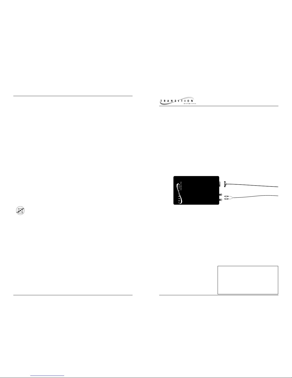
RS232-CF-01
Provides one (1) DB-9 RS-232 copper
connector and one (1) set of RX
(receive) and TX (transmit) ST
100BASE-FX connectors to
multimode fiber (62.5/125) @
850 nM.
DB-9
Fiber
RS232 to Fiber
Media Converter
CAUTION: RJ connectors are NOT INTENDED FOR CONNECTION TO THE
PUBLIC TELEPHONE NETWORK. Failure to observe this caution could result in
damage to the public telephone network.
Der Anschluss dieses Gerätes an ein öffentlickes Telekommunikationsnetz in den EG-Mitgliedstaaten
verstösst gegen die jeweligen einzelstaatlichen Gesetze zur Anwendung der Richtlinie 91/263/EWG zur
Angleichung der Rechtsvorschriften der Mitgliedstaaten über Telekommunikationsendeinrichtungen
einschliesslich der gegenseitigen Anerkennung ihrer Konformität.
RS232-CF-01 in the Network . . . . . . .2
Installation . . . . . . . . . . . . . . . . . . . .3
Operation . . . . . . . . . . . . . . . . . . . . .4
Fault Isolation and Correction . . . . .5
Cable Specifications . . . . . . . . . . . . .6
Technical Specifications . . . . . . . . . .7
Compliance Information . . . . . . . . . .8
Page 2
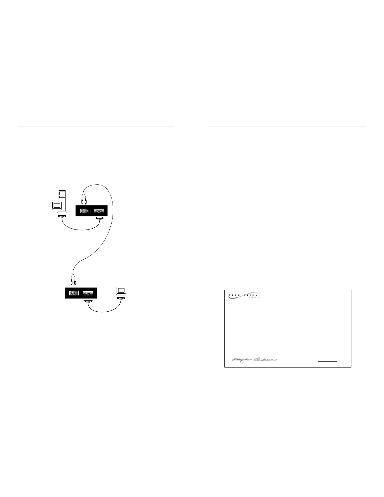
RS232-CF-01 IN THE NETWORK
The RS232-CF-01 can be used to install a fiber network extension between
DTEs or between a DTE and a DCE.
A straight-through cable configuration is required for installation between DTEs.
A null modem cable configuration is required for installation between a DTE
and a DCE. (See page 6.)
TECHNICAL SPECIFICATIONS
Standards TIA/EIA-574
Data Rate 1200-115,000 bits per second
Optical Loss Budget ª10dB
Case Dimensions 5.7" x 3.0" x 1.8" (145mm x 76mm x 46mm)
Shipping Weight 3 pounds (1.4 kilograms)
Environment Temperature: 0-50°C (32° to 122° F )
Humidity 10-90%, non condensing
Altitude 0-10,000 feet
Power Supply Requirements
Replace power supply with only the equivalent input
rating (see below) and output rating (regulated 9VDC at 500 mA).
TN PN Requirement Location
3517 240 volts, 50 hertz United Kingdom
3516 230 volts, 50 hertz Europe
3518 120 volts, 60 hertz USA/Canada/Mexico
3514 100 volts, 50-60 hertz Japan
3515 240 volts, 50 hertz Australia
Power Consumption <100mA
Warranty Lifetime
DECLARATION OF CONFORMITY
Name of Mfg: Transition Networks
6475 City West Parkway, Minneapolis MN 55344 USA
Model: RS232-CF-01Series Serial-Port Extension Media Converters
Part Number(s): RS232-CF-01, RS232-CF-01(SM)
Regulation: EMC Directive 89/336/EEC
Purpose: To declare that the RS232-CF-01 to which this declaration refers is in
conformity with the following standards.
EMC-CISPR 22: 1985 Class A; EN 55022: 1988 Class A; EN 50082-1:1992;
EN 60950 A4:1997; IEC 801.2, IEC 801.3, and IEC 801.4; IEC 950
I, the undersigned, hereby declare that the equipment specified above conforms to the
above Directive(s) and Standard(s).
_July 1, 1999_____
Stephen Anderson, Vice-President of Engineering Date
RS-232 STRAIGHT THROUGH
CONFIGURATION CABLE
RS-232 STRAIGHT THROUGH
CONFIGURATION CABLE
DTE
DTE
NOTE: SHIELDED CABLES REQUIRED ON DB-9 FOR
EMC COMPLIANCE.
Page 3

CABLE SPECIFICATIONS
The physical characteristics of the media cable must meet or exceed TIA/EIA232-F (2.1.4) specifications.
Fiber Cable
MULTIMODE
Fiber Optic Cable Recommended: 62.5 / 125 µm multimode fiber
Optional: 100 / 140 µm multimode fiber
85 / 125 µm multimode fiber
50 / 125 µm multimode fiber
Fiber Optic Transmitter Power: -28.0 dBm
Fiber Optic Receiver Sensitivity: -38.0 dBm
Wavelength : 850nm
Bit error rate: ≤10-9
Maximum Cable Distance: 2 kilometers
RS-232 Copper Cable
Gauge 24 to 22 AWG
Attenuation 20 dB/1000’ @ 10 MHz
Differential Characteristic Impedance 100 Ω ±10% @ 10 MHz
Maximum Cable Distance: <15 feet
RS-232 SIGNALS
INSTALLA TION
NOTE: Ensure that two (2) recessed switches located at side of media converter
are set to the UP position. (Use small flatblade screwdriver or similar device to
set switch position, if necessary.)
Install Cable
COPPER
NOTE: Shielded cables required on DB-9 for EMC compliance.
• Locate or build TIA/EIA-574 compliant cables with male DB-9
connectors and with straight-through cable configuration for connection
to DTE and/or with null-modem cable configuration for connection to
DCE. (See below.)
• Connect male DB-9 connector at one end of cable to media converter
female DB-9 connector.
• Connect male DB-9 connector at other end of cable to DTE female DB-9
connector (using straight-through cable configuration) or to DCE female
DB-9 connector ( using null-modem cable configuration).
FIBER
• Connect male TXand RX cable connectors at one end of cable to TX
and RX female connectors, respectively, on media converter.
Connect to Power
• Install power adapter cord at back of media converter.
• Connect power adapter plug to AC power.
• Verify that media converter is powered by observing illuminated
LED(s).
9
8
7
6
6
7
8
9
1
5
4
3
2
5
1
2
3
4
Null Modem Configuration Cable
with Full Handshaking*
*Particular requirements for different equipment may vary.
9
8
7
6
9
8
7
6
1
5
4
3
2
1
5
4
3
2
Straight Through Configuration Cable
Data Carrier Detect
Data Set Ready
Receive Data
Request to Send
Transmit Data
Clear to Send
Data Terminal Ready
Ring Indicator
Signal Ground
Protective Ground
1
5
4
3
2
9
8
7
6
Page 4

OPERA TION
After installation, the media converter should function without operator
intervention.
NOTE: A temporary interruption of data flow during some types of transients
may require the software to recover. No operator intervention is required at
media converter.
Status LEDs:
Use the status LEDs to monitor media converter operation in the network.
P(o)w(e)r Steady green LED
indicates connection to
external power
L(o)ck Steady green LED
indicates that fiber link
is in functional “lock”
condition.
FAULT ISOLATION and CORRECTION
If the media converter fails, isolate and correct the failure by determining the
answers to the following questions and then taking the indicated action:
1. Is the P(o)w(e)r LED on the media converter illuminated?
NO
• Ensure that media converter is seated firmly in E-MCC-1600 chassis?
• Contact Technical Support at (800) 260-1312/ (800) LAN-WANS.
YES
• Proceed to step 2.
2. Is the L(o)ck LED illuminated?
NO
• Check fiber cables for proper connection.
• Contact Technical Support at (800) 260-1312/ (800) LAN-WANS.
YES
• Proceed to step 3.
3. Does data fail to move across link, even though both LEDs are
illuminated?
YES
• Check RS-232 cables for proper connection.
• Contact Technical Support at (800) 260-1312/ (800) LAN-WANS.
MM Fiber
MM Fiber
DB-9
DB-9
Pwr
Pwr
Lck
Lck
Lck
Pwr
 Loading...