

Transition Networks PSIII-1/7-11, PSIII-1/7-11-T, PSIII-1/7-45, PSIII-1/7-45-T, PSIII-2/14-11 User Manual
...Page 1

7335.F
™
PowerStar
III
(PSIII-1/7-11, PSIII-1/7-45, PSIII-1/7-11-T,
PSIII-1/7-45-T, PSIII-2/14-11, PSIII-2/14-45,
PSIII-2/14-11-T, PSIII-2/14-45-T
)
For assistance in installing, using, or
maintaining the TRANSITION Networks
PowerStar™ III, contact TRANSITION
Networks Technical Support at:
(800) 260-1312
or contact your local distributor.
PowerStar™ III Technical Specifications
Host Connection
IBM®S/3x (System 34, 36, 38), AS/400™ Host or AS/400™ Controllers
Physical Dimensions
8.6" x 6" x 1.7" (219 mm x 153 mm x 43 mm)
OR
17.0"
x 7.5" x 1.7" (432 mm x 191 mm x 43 mm)
Input Power
Power Supply Adapter
AC Input:
TN PN Requirement Location
3500 120 volts, 60 hertz, 28 watts USA/Canada/Mexico
3501 230 volts, 50 hertz, 28 watts Europe
3506 240 volts, 50 hertz, 28 watts United Kingdom
3508 100 volts, 50-60 hertz, 28 watts Japan
3510 240 volts, 50 hertz, 28 watts Australia
DC Output:
12 volts at 1.5 A maximum
MTBF:
116,000-140,000 hours (depending upon model)
Environment
Temperature: 0-50°C (32° to 122° F )
Humidity 10-90%, non condensing
Altitude 0-10,000 feet
Warranty
5 years
21
Page 2

PowerStar™ III
20
CAUTION: RJ connectors are NOT INTENDED FOR
CONNECTION TO THE PUBLIC TELEPHONE
NETWORK. Failure to observe this caution could result
in damage to the public telephone network.
Compliance Information
UL Listed
C-UL Listed (Canada)
CISPR/EN55022 Class A
FCC Regulations
This equipment has been tested and found to comply with the limits for a class
A digital device, pursuant to part 15 of the FCC rules. These limits are
designed to provide reasonable protection against harmful interference when
the equipment is operated in a commercial environment. This equipment
generates, uses, and can radiate radio frequency energy and, if not installed
and used in accordance with the instruction manual, may cause harmful
interference to radio communications. Operation of this equipment in a
residential area is likely to cause harmful interference, in which case the user
will be required to correct the interference at the user’s own expense.
Canadian Regulations
This digital apparatus does not exceed the Class A limits for radio noise for
digital apparatus set out on the radio interference regulations of the Canadian
Department of Communications.
European Regulations
Warning
This is a Class A product. In a domestic environment this product may cause
radio interference in which case the user may be required to take adequate
measures.
Copyright Restrictions
© 1994, 1996 TRANSITION Networks Inc.
All rights reserved. No part of this work may be reproduced or used in any
form or by any means – graphic, electronic, or mechanical – without written
permission from TRANSITION Networks Inc.
Trademark Notice
All registered trademarks and trademarks are the property of their respective
owners.
Der Anschluss dieses Gerätes an ein öffentlickes
Telekommunikationsnetz in den EG-Mitgliedstaaten verstösst gegen die
jeweligen einzelstaatlichen Gesetze zur Anwendung der Richtlinie
91/263/EWG zur Angleichung der Rechtsvorschriften der
Mitgliedstaaten über Telekommunikationsendeinrichtungen
einschliesslich der gegenseitigen Anerkennung ihrer Konformität.
Twinax Cable and Connector Specifications
Cable Characteristics:
Twinax cable consists of conductors - one tinned and one solid copper - in a
tinned copper braid shield, with impedance of 100 ohms.
Cable Type IBM PN or equivalent
Twinax Plenum 7362061
Twinax PVC 7362211
Minimum Cable Distance:
Host to Product 7.6 meters (25 feet)
Product to Product 7.6 meters (25 feet)
Product to Terminal Device not applicable
Maximum Cable Distance:
Host to Product 1500 meters (5,000 feet)
Product to Product 1500 meters (5,000 feet)
Product to Terminal Device not applicable
Connector Characteristics:
Twinax connectors (IBM or equivalent) can be connected to twinax cable. (The
last twinax connection in a daisy-chain must be terminated.)
Fiber Cable and Connector Specifications
The physical characteristics of the fiber cable must meet or exceed the following:
Cable Characteristics:
Fiber Optic Cable Recommended: 62.5 / 125 µm multimode fiber
Optional: 100 / 140 µm multimode fiber
85 / 125 µm multimode fiber
50 / 125 µm multimode fiber
Fiber Optic Transmitter Power: Average power: -15.0 dBm
Peak power:-12.0 dBm ±1dBm
Fiber Optic Receiver Sensitivity: Average sensitivity: -27.4 dBm
Bit error rate: ≤10
-10
Minimum Cable Distance:
Host to Product 7.6 meters (25 feet)
Product to Product 7.6 meters (25 feet)
Product to Terminal Device not applicable
Maximum Cable Distance:
Host to Product 3000 meters (10,000 feet)
Product to Product 3000 meters (10,000 feet)
Product to Terminal Device not applicable
Connector Characteristics:
ST type connectors (SMA type available upon request)
Page 3
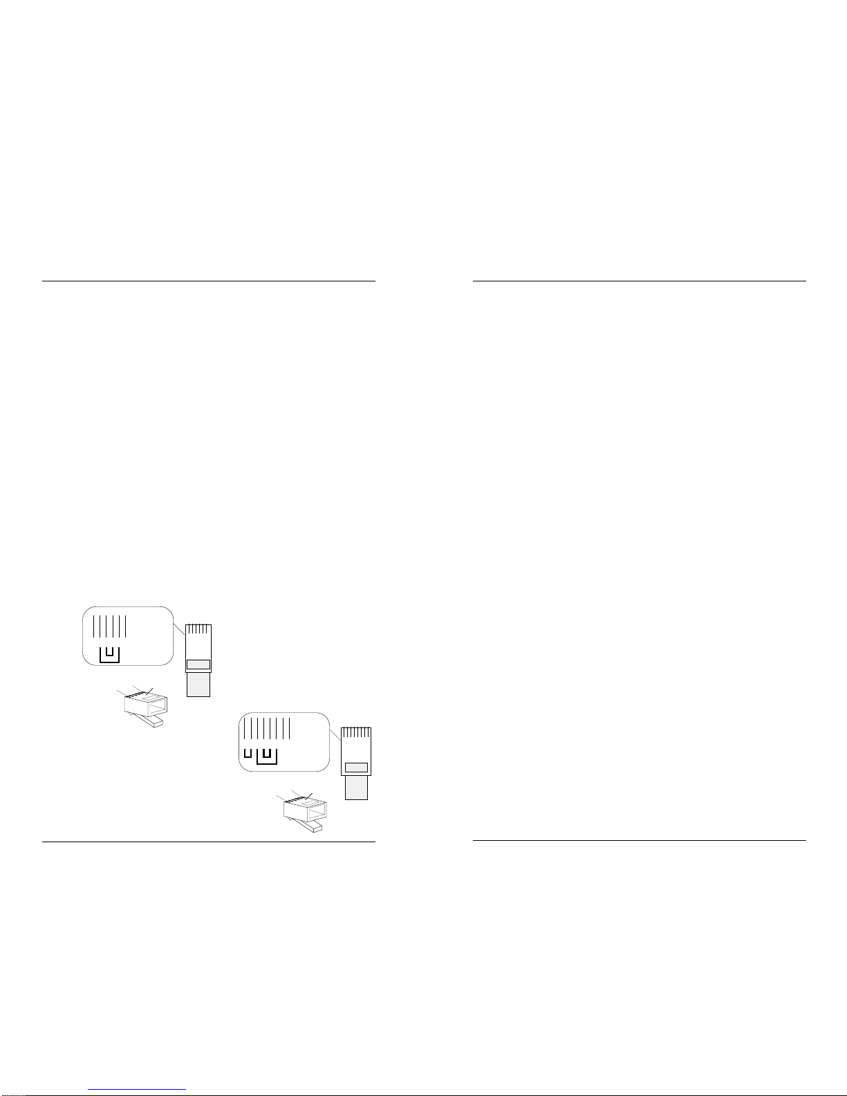
Table of Contents
1 INTRODUCTION . . . . . . . . . . . . . . . . . . . . . . . . . 1
The PowerStar™ III . . . . . . . . . . . . . . . . . . . . . . . . . . . . . . . .1
Networking the PowerStar™ III . . . . . . . . . . . . . . . . . . . . . . .2
Connectors, Switches, and Status Indicators . . . . . . . . . . . . .3
2 SITE CONSIDERATIONS. . . . . . . . . . . . . . . . . . . . 4
3 INSTALLATION. . . . . . . . . . . . . . . . . . . . . . . . . . . 5
Unpacking PowerStar™ III . . . . . . . . . . . . . . . . . . . . . . . . . . .5
Setting Pin Jumpers . . . . . . . . . . . . . . . . . . . . . . . . . . . . . . . .6
Installing PowerStar™ III in Rack or on Table . . . . . . . . . . . .9
Setting Twisted Pair Polarity Switch . . . . . . . . . . . . . . . . . . .10
Connecting Link Cable to Host . . . . . . . . . . . . . . . . . . . . . .11
Connecting Twisted Pair Link Cable . . . . . . . . . . . . . . . . . . . .11
Connecting Twinax Link Cable . . . . . . . . . . . . . . . . . . . . . . . .13
Connecting Port Cable to Terminal Devices . . . . . . . . . . . .15
Powering the PowerStar™ III . . . . . . . . . . . . . . . . . . . . . . . .16
4 OPERATION. . . . . . . . . . . . . . . . . . . . . . . . . . . . 16
5 MAINTENANCE . . . . . . . . . . . . . . . . . . . . . . . . . 16
POLICY AND PROCEDURE . . . . . . . . . . . . . . . . . . . . . . . . . 17
CABLE SPECIFICATIONS. . . . . . . . . . . . . . . . . . . . . . . . . . . . 19
POWERSTAR™ III TECHNICAL SPECIFICATIONS . . . . . . 21
i
19
PowerStar™ III
AS/400 and S/36 Cable Specifications
Twisted Pair Cable and Connector Specifications
The physical characteristics of the twisted pair cable must meet or exceed the
following:
Category 3 wire or better is required; category 5 wire is recommended. Either
shielded twisted pair (STP) or unshielded twisted pair (UTP) can be used.
Gauge 26 to 22 AWG
Attenuation Less than 11.5 dB @ 5-10 MHz
Differential Characteristic Impedance 85 -110 Ω @ 10 MHz
DO NOT USE FLAT OR “SILVER SATIN” WIRE.
Minimum Cable Distance:
Host to Product 7.6 meters (25 feet)
Product to Product 7.6 meters (25 feet)
Product to Terminal Device 7.6 meters (25 feet)
Maximum Cable Distance:
Host to Product 762 meters (2500 feet)
Product to Product 762 meters (2500 feet)
Product to Terminal Device 762 meters (2500 feet)
Connector Characteristics:
Twisted pair connection requires one active pair configured as straight through.
When using RJ-11 connectors, the
active pair can be pins 2 & 5 or pins 3
& 4.
When using RJ-45 connectors, the
active pair can be pins 1 & 2, pins 4 &
5 or pins 3 & 6.
16
Top View
of the
RJ-11 Cable
Connector
1 2 3 4 5 6
Thick lines
indicate
pairs
Thin lines
indicate
pin leads
1
6
Crossview
of the RJ-11
Cable Connector
Top
1 2 3 4 5 6 7 8
Top View
of the
RJ-45 Cable
Connector
Thick lines
indicate
pairs
Thin lines
indicate
pin leads
1
8
Crossview
of the RJ-45
Cable Connector
Top
18
Page 4

18
1
PowerStar™ III
1. INTRODUCTION
This guide is intended for the system or network administrator
responsible for installing and monitoring a TRANSITION Networks
PowerStar™ III. A working knowledge of AS/400™ peripheral
connections and operations, including familiarity with communications
protocols used, is assumed.
The PowerStar™ III
The PowerStar™ III, available in various models (PSIII-1/7-11, PSIII-1/745, PSIII-1/7-11-T, PSIII-1/7-45-T, PSIII-2/14-11, PSIII-2/14-45, PSIII2/14-11-T, PSIII-2/14-45-T), is an active star repeater for AS/400™ and
S/3x environments that can be used for converting a twinax daisy chain
topology to an unshielded twisted pair star topology.
• The PowerStar III is designed to support all 5250 compliant devices
operating at approximately 1Mbps.
• Host controller link can be connected either through a twisted pair
connector at the front of the PowerStar™ III or, if the optional
twinax connector is installed, through the twinax connector at the
back of the PowerStar™ III.
• Twisted pair port connections are identified, by PowerStar™ III
model number, as either RJ-11 or RJ-45 connectors.
• Separate transceiver circuitry isolates each port.
• The following pin configurations are selectable:
RJ-11 pins 3 & 4 or 2 & 5 optionally active
(factory default: pins 3 & 4 active)
RJ-45 pins 1 & 2, 3 & 6, or 4 & 5 optionally active;
(factory default: pins 4 & 5 active).
PowerStarIII
Link
01 23456
Line Sync
Parity Error
Link
01 23456
Line Sync
Parity Error
The sole purpose of this remedy shall be provided the customer with the replacement or
repair of non-conforming goods in the manner described in this Warranty statement. This
exclusive remedy shall not be deemed to have failed of its essential purpose so long as TN is
willing and able to repair or replace the defective item(s) or refund the purchase price.
TN reserves the right to inspect products claimed to be defective under warranty either at the
customer’s location or at TN’s plant. TN assumes no liability for liability charges incidental
to the adjustment, service, repairing, removal or replacement of the product, or other costs,
or the expense of repairs made outside of its factory, except when made with TN’s prior
written consent. Additionally, Transition Networks reserves the right to charge for all testing
and shipping incurred, if after testing, a return is classified as “No Problem Found”.
TN’s total liability in connection with the products and their installation to all persons and
from all causes in the aggregate, whether in contract, tort, or strict liability, shall not exceed
the amount paid to TN for the product directly related to the alleged damage. However, in
no event shall TN have any liability to a customer or any third party for products
manufactures according to the customer’s specifications.
C. Return Procedure
The customer must follow this procedure for the return of defective items:
1. Locate the serial number(s) of the item(s) to be returned.
2. Determine the date the item(s) was received.
3. Contact Transition Networks Technical Support to determine if the problem can be
corrected on site.
If not, and the product is covered by warranty, then:
• Call the distributor directly or contact TN.
• Request a Return Material Authorization (RMA).
• Ship the item, prepaid in original packaging to Transition Networks at the above
address.
• Include the RMA number on the outside of the carton and/or on the Packing List.
• Include a copy of the RMA form.
• Include a copy of the original invoice or packing list (if possible) to expedite
processing.
• The item(s) may be shipped by the customer or the distributor.
• Transition Networks will repair or replace the unit, at TN’s discretion, and cover the
cost of the return freight to the distributor or to the customer, whichever requested
the RMA number.
If the item(s) was received more than five years ago, or if the item(s) is no longer covered by
warranty for other reasons, then:
• Call the distributor or contact TN.
• Request a Material Repair Authorization number (MRA).
• Ship the item(s), prepaid, in the original packaging to Transition Networks at the
above address.
• Include the MRA number on the outside of the carton add/or on the Packing List.
• Include a copy of the MRA form.
• Include a copy of the original invoice or packing list (if possible) to expedite processing.
• Only the customer (end-user) may send the items(s) to TN.
• TN will contact the customer after the item(s) have been received, inspected, and a
cost estimate of the repair determined.
• The repair charges may be billed, with customer’s approval, though the distributor, or
on a prepaid or C.O.D. basis directly to the customer. The charges will include the
cost of shipping.
The return authorization numbers are valid only for 90 days from the date issued.
Front of PSIII-2/14-45 or of PSIII-2/14-45-T
Page 5

2
17
PowerStar™ III
Networking the PowerStar™ III
Depending on model, the PowerStar™ III distributes one or two host
input signals from an AS/400, Sys36, or 5x94 remote controller, over
twinax or twisted pair media, to seven or fourteen terminal devices.
All signals to the terminal devices are over twisted pair.
NOTE: The PowerStar™ III must be one of the models with an
installed twinax connector (indicated by “-T” at the end of the model
number) to be used for the twinax link connection.
OR
Warranty Statement
A. Five Year Warranty
Transition Networks, Inc. (TN) warrants, for a period of five years, that TN products (with
the exception of power supplies and fans that TN warrants for two years) will be free from
defects in materials and workmanship, and will be in conformity with TN’s specifications.
TN’s warranty on products manufactured by or assembled for TN in accordance with a
customer’s specifications, is a five-year warranty that the goods conform to such
specifications.
The warranty is invalidated if the goods have been subject to alterations, misuse, accident,
Acts of God (e.g., damage by floods, lightning strikes, Etc.), tampering, improper
maintenance, improper maintenance, improper installation, or abuse. If the user is unsure
about the proper means of installing or using the equipment, contact TN’s free Technical
Support or Network Design Services, which can be reached by:
Telephone 1.800.LAN.WANS or 612.941.7600
Fax 612.941.2322
E-mail techsupport@transition.com
Internet http://www.transition.com
THE ABOVE WARRANTY IS EXCLUSIVE AND EXTENDS ONLY TO PRODUCTS
ASSEMBLED BY TRANSITION NETWORKS, INC. TO THE EXTENT PERMITTED BY LAW,
TN DOES NOT MAKE AND DISCLAIMS ALL OTHER WARRANTIES, EXCEPT TITLE,
EXPRESSED OR IMPLIED, INCLUDING, BUT NOT LIMITED TO, ANY WARRANTY OF
DESCRIPTION, MERCHANTIBILITY, FITNESS FOR A PARTICULAR PURPOSE OR NONINFRINGEMENT, AND ANY WARRANTY BASED UPON PRIOR WRITTEN OR ORAL
REPRESENTATIONS REGARDING SUCH PRODUCTS MADE BY TN, ITS EMPLOYEES,
AGENTS, OR REPRESENTATIVES.
B. Limitations and Exclusions
If the customer believes any goods sold by TN are defective and within the warranty period,
the following general procedure will be followed:
1. Locate the serial number and delivery date of the item(s).
2. Notify TN within the warranty period.
3. TN will promptly issue a return authorization form for the goods.
4. Upon receiving the form, the customer will promptly return the item(s) at customers
own expense, shipped prepaid, to the distributor from which it was purchased, or
directly to TN.
TN will only accept goods for return if the following conditions have been met:
1. A return form is obtained from TN.
2. The freight charges have been prepaid by the customer.
3. Goods are re-packed in their original packaging.
If under warranty TN shall, at its option, (1) repair the goods free of charge (2) replace the
goods free of charge, or (3) accept the return of the item(s) and credit the current price to
the reseller (within 90 days of purchase), or (4) if the goods are not under warranty, will
repair the item(s) at a minimum charge of USD $200 (two hundred U.S. dollars) per item.
THIS IS THE EXCLUSIVE REMEDY FOR ANY BREACH OF WARRANTY. IN NO EVENT
SHALL TRANSITION NETWORKS BE LIABLE FOR SPECIAL, INDIRECT, INCIDENTAL OR
CONSEQUENTIAL DAMAGES OF ANY KIND, WHETHER FOR BREACH OF ANY
CONDITION OF SALE, FOR NEGLIGENCE, ON THE BASIS OF STRICT LIABILITY,
CONTRACT, OR OTHERWISE AND IRRESPECTIVE OF WHETHER TN IS INFORMED BY
CUSTOMER OF THE POSSIBILITY OF SUCH DAMAGES IN ADVANCE OF THIS SALE.
Page 6

16
3
PowerStar™ III
Powering the PowerStar™ III
To power ON the PowerStar™ III:
1. Locate the power receptacle on the back of the PowerStar™ III.
2. Connect the PowerStar™ III power connector end of the power
supply adapter to the PowerStar™ III.
3. Connect the external power connector end of the power
supply adapter to external AC power.
NOTE: After the power supply adapter is connected to the PowerStar™
III and to external power, the green Power LED is illuminated.
4. OPERATION
The PowerStar™ III normally requires no intervention beyond
occasionally monitoring the status LEDs.
5. MAINTENANCE
WARNING: DO NOT, UNDER ANY CIRCUMSTANCES, open
and attempt to repair the PowerStar™ III. Failure to observe
this warning could result in personal injury or death from
electrical shock.
NOTE: Failure to observe the above warning will immediately void the
warranty.
Technical Support Contact
For assistance in fault isolation and in maintaining the PowerStar™ III,
contact:
Technical Support (800) 260-1312
or your local distributor.
Connectors, Switches and Status Indicators
Connectors
One Link (host) connector is provided on the 7-port PowerStar™ III; two
Link (host) connectors are provided on the 14-port PowerStar™ III.
These connectors each provide an RJ twisted pair link to AS/400™ or
S/3x host signals. Seven (7) or fourteen (14) terminal device connectors,
labeled 0, 1, 2, 3, 4, 5, or 6, provide RJ twisted pair connection for
distributing the AS/400™ or S/3x host signals to terminal devices.
(AT BACK) PowerStar™ III models with “-T” at the end of the model
number provide one or two twinax host connectors. A connector to
external power also is located at the back of the PowerStar™ III.
Status Indicators (LEDs)
Line Sync (illuminated during normal operation) and Parity Error (blinks
at error) status indicators (LEDs) are provided next to each twisted pair
RJ connector for monitoring data transfer from host to link and from link
to port.The Power LED indicates PowerStar™ III connection to external
power.
Switches (ON BACK)
The Polarity Setting Switches are used to set the polarity sense of the
active RJ pins for the Link (host) and for the Port (terminal device)
connections. (See page 10.)
PowerStarIII
Link
01 23456
Line Sync
Parity Error
Link
01 23456
Line Sync
Parity Error
ower Indicator
Power
RJ-45 (or RJ-11) Connector
Line Sync Indicator
Parity Error Indicator
Left Link Connector
Right Link Connector
3
Page 7

4
15
PowerStar™ III
2. SITE CONSIDERATIONS
The site for the PowerStar™ III must provide:
• AC power outlet for each PowerStar™ III
• Adequate ventilation
• Standard environmental conditions
• Isolation from electrical noise, including radio transmitters and
broadband amplifiers, motors, high power electrical lines, or
fluorescent light fixtures.
Additionally:
• The twisted pair cables should not run in the same conduit
with power line cables,
• Phone lines should be separated from data cables,
• Flat or “silver satin” wires should not be used.
And:
• Unshielded twisted pair, twinax, and fiber optic cable lengths
must be greater than 25 feet (7.6 meters),
• If twisted pair cable is used, the RJ-11 or RJ-45 connector pin
settings must be configured as shown on page 8, compatible
baluns must be selected according to the chart below, and the
polarity switch must be set as shown on page 10.
Connector Pins TN Balun
RJ-11 3 & 4 3-1134
RJ-11 4 & 3 3-1143
RJ-11 2 & 5 3-1125*
RJ-11 5 & 2 3-1152
RJ-45 1 & 2 3-4512
RJ-45 2 & 1 3-4521
RJ-45 3 & 6 3-4536
RJ-45 6 & 3 3-4563
RJ-45 4 & 5 3-4545
RJ-45 5 & 4 3-4554
*Same active pins as used in IBM baluns P/Ns 69x7883 and 96x6187.
Connecting Port Cable to Terminal Devices
NOTE: When twisted pair cable is used, compatible baluns must
be selected according to the chart on page 4, the RJ-11 or RJ-45
connector pin settings must be configured as shown on page 8,
and the polarity switch must be set as shown on page 10.
NOTE: Terminal devices must be connected ONLY to port
connectors that carry an installed link signal.
To connect twisted pair cable from PowerStar™ III ports to
terminal devices:
1. Locate or build twisted pair cables that conform to
specifications on page 23 and to conditions noted above,
with minimum length of 25 feet (7.6 meters) and with
male RJ-11 or RJ-45 plug connectors installed at both
cable ends
2. Install balun at terminal device RJ-11 or RJ-45 jack
connector.
3. Connect male RJ-11 or RJ-45 plug connector at one end of
cable to balun.
4. Connect male RJ-11 or RJ-45 plug connector at other end
of cable to PowerStar™ III RJ-11 or RJ-45 jack connector.
5. Repeat steps 1-4 until all terminal devices are installed.
Page 8

14
5
3. INSTALLATION
To install the PowerStar™ III:
• Unpack the PowerStar™ III.
• Optionally set pin jumpers.
• Install PowerStar™ III in rack or on table.
• Set Twisted Pair Polarity switches.
• Connect link cable to host.
• Connect port cable to terminal devices.
• Connect the PowerStar™ III to power.
Direction is provided in the pages that follow.
Unpacking the PowerStar™ III
The PowerStar™ III packing contents should include the following:
Item Part Number
PowerStar™ III PSIII-1/7-11, PSIII-1/7-45,
PSIII-1/7-11-T, PSIII-1/7-45-T,
PSIII-2/14-11, PSIII-2/14-45,
PSIII-2/14-11-T, PSIII-2/14-45-T
Power Supply Adapter 3500, 3501, 3506, 3508, or 3510,
(depending upon power configuration
in country where installed)
User’s Guide 7335
Page 9

6
13
PowerStar™ III
Optionally Setting Pin Jumpers
NOTE: The default factory setting makes pins 3 & 4 active in the RJ-11
connector and pins 4 & 5 active in the RJ-45 connector.
NOTE: Since pin jumpers are located inside the PowerStar III, the
PowerStar™ III cover must be removed when setting the pin jumpers.
WARNING: DISCONNECT POWER CORD from PowerStar™ III
before setting jumper pins. Failure to observe this warning could result
in personal injury or death from electrical shock.
WARNING: AVOID CONTACT WITH POWER SUPPLY during jumper
pin setting. Failure to observe this warning could result in personal
injury from electrical shock caused by capacitive discharge.
CAUTION: Wear a grounding device and observe electrostatic
discharge precautions when setting pin jumpers. Use needle nosed
pliers with insulated handle. Failure to observe this caution could
result in circuit board failure.
To verify or modify the jumper pin settings:
1. Place PowerStar™ III on table or other stable surface.
2. Using medium Phillips screwdriver, remove three (3) screws
that secure cover to PowerStar™ III left side, three (3) screws
that secure cover to PowerStar™ III right side, and three (3)
screws that secure cover to PowerStar™ III back.
NOTE: Do NOT remove
two (2) screws that
secure power connector.
Connecting Twinax Link Cable
To connect twinax cable to PowerStar™ III twinax connector:
1. Locate or build twinax cables that conform to specifications
on page 20, with minimum length of 25 feet (7.6 meters) and
maximum length of 5000 feet.
2. Connect one end of twinax cable to AS/400, Sys/36, or 5x94
controller port.
3. Connect other end of twinax cable to twinax connector on
PowerStar™ III.
Page 10

12
7
PowerStar™ III
3. Slide PowerStar™ III cover back approximately one inch to
disengage cover from chassis.
4. Carefully lift PowerStar™ III cover and remove.
5. Using needle nose pliers with insulated handle and referring to
reference material on the next page, move jumpers as required
to change factory default active pin settings to active pin
settings for the site.
Page 11

PowerStar™ III
8
11
RJ-11 Pin Settings
Verify that the jumper locations activate the pins required for the
installation.
RJ-45 Pin Settings
Verify that the jumper locations activate the pins required for the
installation.
6. Rotate PowerStar™ III cover to rest again on chassis.
7. Slide cover forward to engage cover against chassis.
8. Replace cover screws.
16
Top View
of the
RJ-11 Cable
Connector
1 2 3 4 5 6
Thick lines
indicate
pairs
Thin lines
indicate
pin leads
1
6
Crossview
of the RJ-11
Cable Connector
Top
2,5
3,4
1,6
PowerStar III Jumpers
PowerStar III Top Front
RJ-11 Pins
NOT USED
1 2 3 4 5 6 7 8
Top View
of the
RJ-45 Cable
Connector
Thick lines
indicate
pairs
Thin lines
indicate
pin leads
1
8
Crossview
of the RJ-45
Cable Connector
Top
3,6
4,5
1,2
7,8
PowerStar III Jumpers RJ-45 Pins
NOT USED
18
PowerStar III Top Front
Pin Settings
The default factory setting for both RJ-11 and RJ-45
configurations is two centered jumpers. This default
setting activates pins 3 & 4 in the RJ-11 connector and
pins 4 & 5 in the RJ-45 connector.
Connecting Link Cable to Host
Connect the AS/400, Sys36, or 5x94 remote controller host to
the PowerStar III using either twisted pair or twinax cable.
NOTE: All cable lengths must be greater than 25 feet (7.6 meters).
Connecting Twisted Pair Link Cable
When installing twisted pair cable, attach a balun to the AS/400™ or
S/3x twinax port, then attach the twisted pair cable between the balun
and the RJ Link connector on the PowerStar III.
CAUTION: Do NOT use a balun to connect twisted pair cable to
twinax cable. A mid-link media change may degrade the signal and
result in data loss.
NOTE: When twisted pair cable is used, compatible baluns must be
selected according to the chart on page 4, the RJ-11 or RJ-45
connector pin settings must be configured as shown on page 8, and
the polarity switch must be set as shown on page 10.
To connect link cable to PowerStar™ III link connectors:
1. Locate or build twisted pair cables that conform to
specifications on page 23 and to conditions noted above, with
minimum length of 25 feet (7.6 meters) and with male RJ-11
or RJ-45 plug connectors installed at both cable ends.
2. Connect male RJ-11 or RJ-45 plug connector at one end of
cable to a Link port on the PowerStar™ III RJ-11 or RJ-45 jack
connector.
3. Connect balun to the twinax port on the host computer.
4. Connect male RJ-11 or RJ-45 plug connector at other end of
cable to balun installed on the host in step 3.
Page 12

PowerStar™ III
10
9
Installing PowerStar™ III in Rack or on Table
NOTE: The 14-port PowerStar™ III is shipped with attached brackets
for standard 19-inch rack installation. All PowerStars™ are shipped
with attachable feet for table-top installation.
To install the PowerStar™ III in 19-inch rack:
1. Locate four (4) screws (NOT PROVIDED) for each PowerStar™
III to be installed.
2. Carefully align the PowerStar™ III at the installation position
between the 19-inch rack mounting rails.
3. Install two screws through right front bracket and two screws
through left front bracket, using clip nuts if necessary.
To install the PowerStar™ III on table or other flat surface:
1. Carefully turn PowerStar™ III to side.
2. Install four (4) rubber feet):
• Remove protective paper from rubber foot adhesive surface.
• Position rubber foot at bottom corner of repeater hub.
• Press rubber foot against PowerStar™ III surface to secure.
• Repeat for remaining rubber feet.
3. Return PowerStar™ III to upright position.
PowerStarIII
Link
01 2345 6
Line Sync
Parity Error
Link
0123456
Line Sync
Parity Error
CAUTION: The rubber feet MUST BE INSTALLED if the PowerStar™
III is installed on a table-top or other flat surface. Failure to observe
this caution could cause the PowerStar™ III to overheat and could
result in data transmission failure and/or equipment damage.
Setting Twisted Pair Polarity Switches
There are two sets of polarity switches at the 14-port PowerStar™ III
front – one set for the left controller or host port and seven device ports
and one set for the right controller or host port and seven device ports –
and one set at the front of the 7-port PowerStar™ III. The A-B switch
settings reverse the polarity of the twisted pair connector active pins.
The factory default setting is "A". The following chart shows, for various
connector/pin options, the correct A-B switch setting and compatible
TRANSITION Networks baluns.
External Polarity Compatible
Connector
Pins Switch Setting TN Balun
RJ-11 3 & 4 A 3-1143
RJ-11 " B 3-1134
RJ-11 2 & 5 A 3-1152
RJ-11 " B 3-1125
RJ-45 1 & 2 A 3-4521
RJ-45 " B 3-4512
RJ-45 3 & 6 A 3-4563
RJ-45 " B 3-4536
RJ-45 4 & 5 A 3-4554
RJ-45 " B 3-4545
NOTE: Set the Link Ports polarity switch to “A” when installing twinax
cable to the host.
Ports 0-6
Link
Twinax
RJ-45
Main Link Input Select
Polarity Settings
Ports 0-6
Link
Twinax
RJ-45
Main Link Input Select
Polarity Settings
Ports 0-6
Link
Twinax
RJ-45
Main Link Input Select
Polarity Setting Switches
 Loading...