

Page 1
COMPLIANCE INFORMATION
UL Listed
C-UL Listed (Canada)
CISPR/EN55022 Class A
FCC Regulations
This equipment has been tested and found to comply with the limits for a class A digital device, pursuant
to part 15 of the FCC rules. These limits are designed to provide reasonable protection against harmful
interference when the equipment is operated in a commercial environment. This equipment generates,
uses, and can radiate radio frequency energy and, if not installed and used in accordance with the
instruction manual, may cause harmful interference to radio communications. Operation of this
equipment in a residential area is likely to cause harmful interference, in which case the user will be
required to correct the interference at the user’s own expense.
Canadian Regulations
This digital apparatus does not exceed the Class A limits for radio noise for digital apparatus set out on
the radio interference regulations of the Canadian Department of Communications.
Le présent appareil numérique n'émet pas de bruits radioélectriques dépassant les limites applicables
aux appareils numériques de la class A prescrites dans le Règlement sur le brouillage radioélectrique
édicté par le ministère des Communications du Canada.
European Regulations
Warning
This is a Class A product. In a domestic environment this product may cause radio interference in which
case the user may be required to take adequate measures.
Achtung !
Dieses ist ein Gerät der Funkstörgrenzwertklasse A. In Wohnbereichen können bei Betrieb dieses Gerätes
Rundfunkstörungen auftreten, in weichen Fällen der Benutzer für entsprechende Gegenmaßnahmen
werantwortlich ist.
Attention !
Ceci est un produit de Classe A. Dans un environment domestique, ce produit risque de créer des
interférences radioélectriques, il appartiendra alors à l’utilsateur de prende les measures spécifiques
appropriées
Trademark Notice
All registered trademarks and trademarks are the property of their respective owners.
Copyright Restrictions
© 1999-2001 TRANSITION Networks.
All rights reserved. No part of this work may be reproduced or used in any form or by any means –
graphic, electronic, or mechanical – without written permission from TRANSITION Networks.
Printed in the U.S.A. 33119.D
CAUTION: RJ connectors are NOT INTENDED FOR CONNECTION TO THE
PUBLIC TELEPHONE NETWORK. Failure to observe this caution could result in
damage to the public telephone network.
Der Anschluss dieses Gerätes an ein öffentlickes Telekommunikationsnetz in den EG-Mitgliedstaaten
verstösst gegen die jeweligen einzelstaatlichen Gesetze zur Anwendung der Richtlinie 91/263/EWG zur
Angleichung der Rechtsvorschriften der Mitgliedstaaten über Telekommunikationsendeinrichtungen
einschliesslich der gegenseitigen Anerkennung ihrer Konformität.
The TRANSITION Networks J/FE-CF-01 series Fast Ethernet™ media
converters connect either unshielded or shielded 100BASE-TX twisted-pair
copper cable to 100BASE-FX multimode fiber-optic cable.
The AutoCross™ feature allows either straight-through (MDI) or crossover (MDI-X)
cables to be used when connecting to 100BASE-TX devices, such as hubs,
transceivers, or network interface cards (NICs). AutoCross™ determines the
characteristics of the cable connection and automatically configures the unit to
link up, regardless of the cable configuration.
The LinkALERT™ feature allows the J/FE-CF-01 media converter to pass 100BASETX side link faults to the
100BASE-FX side and to pass 100BASE-FX side link faults
to the 100BASE-TX side.
Minneapolis, MN 55344 USA
Fast Ethernet
™
Media Converters
J/FE-CF-01(ST), J/FE-CF-01(SC)
USER’S GUIDE
J/FE-CF-01 in the Network . . . . . . . .2
Installation . . . . . . . . . . . . . . . . . . . .3
Operation . . . . . . . . . . . . . . . . . . . . .4
Fault Isolation and Correction . . . . .4
Cable Specifications . . . . . . . . . . . . .6
Technical Specifications . . . . . . . . . .7
Compliance Information . . . . . . . . . .8
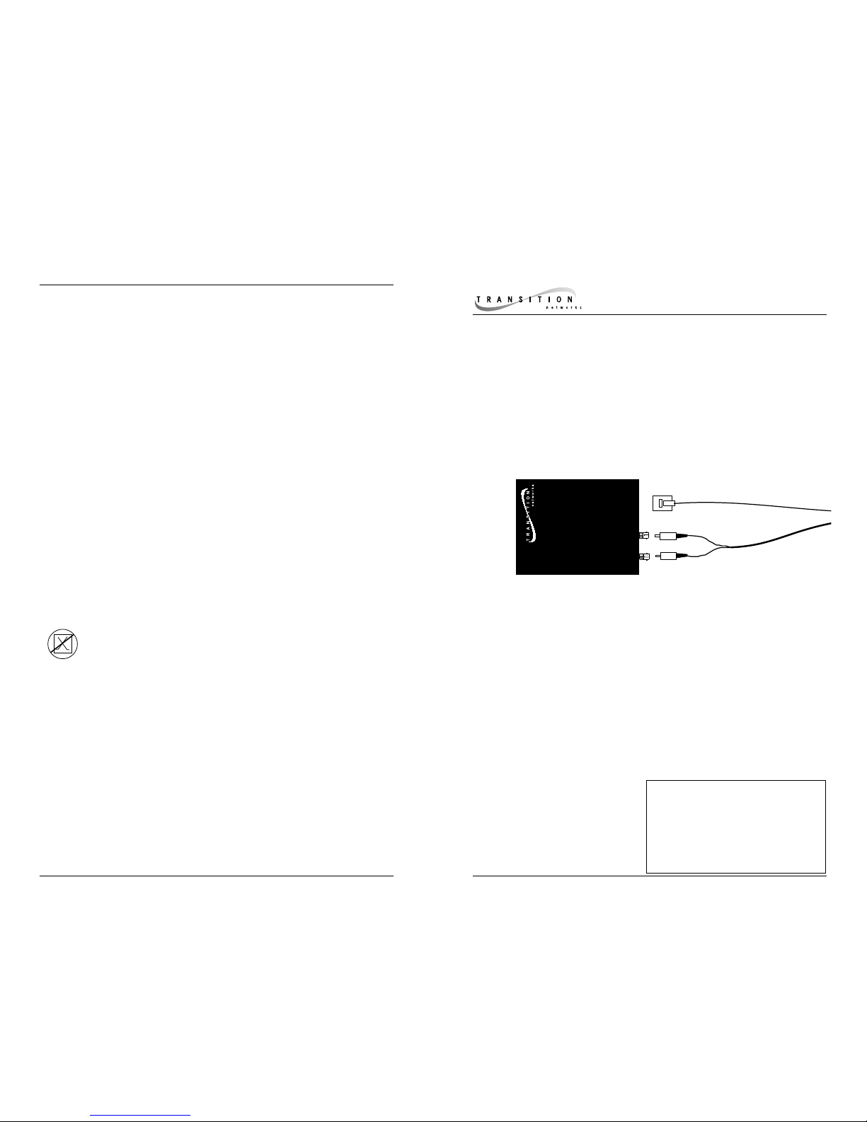
J/FE-CF-01(ST)
Provides an RJ-45 twisted pair copper
connector and a set of RX (receive) and
TX (transmit) ST connectors to
multimode fiber-optic cable.
J/FE-CF-01(SC)
Provides an RJ-45 twisted pair copper
connector and an RX (receive) and TX
(transmit) SC connector to multimode
fiber-optic cable.
Page 2
J/FE-CF-01 IN THE NETWORK TECHNICAL SPECIFICATIONS
Standards IEEE 802.3u
Case Dimensions 4.0" x 3.25" x 1.0" (102 mm x 83 mm x 25 mm)
Power Supply Requirements Replace power supply with only the equivalent
input rating (see below) and output rating (regulated 12VDC at 500 mA).
TN PN Requirement Location
25010 240 volts, 50 hertz United Kingdom
25009 230 volts, 50 hertz Europe
25007 120 volts, 60 hertz USA/Canada/Mexico
25020 100 volts, 50-60 hertz Japan
25023 240 volts, 50 hertz Australia
Environment Typical Operating Temperature: 0°
to 50°C (32°to 122°F )
Storage Temperature: -20°to 85°C (-4°
to
185°F)
Humidity 10-90%, non condensing
Altitude 0-10,000 feet
Warranty Lifetime
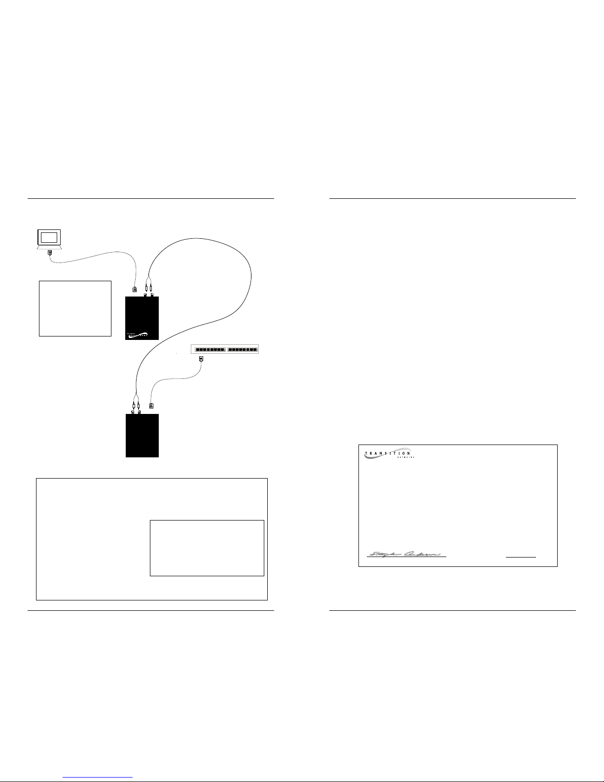
2 kilometers - multimode
100 meters
100 meters100 meters
100 meters
100BASE-TX/100BASE-FX
Full-Duplex Network
To calculate the round trip delay (in bit-times) in a half-duplex Fast
Ethernet™ network collision domain, find the longest path in the collision
domain. Calculate the round trip
delay for each cable segment in the
collision domain by multiplying the
length of the cable (in meters) by the
delay per meter (in bit-times (BT)).
Calculate the total round trip delay
by taking the sum of all the cable
delays plus station (DTE) and
repeater delays. If the result is less than or equal to 512 bit-times, the path
passes the test. NOTE: The J/FE-CF-01 has a 50 BT delay.
Class I Repeater 140 BT
Class II Repeater 92 BT
Class I TX/FX Media Converter 130 BT
Class II TX/FX Media Converter 92 BT
DTE 50 BT
1 meter of CAT.5 TP cable 1.11 BT
1 meter of fiber cable 1 BT
Fast Ethernet Switch 50 BT
100BASE-TX/100BASE-FX Half-Duplex Collision Domain
512-Bit Rule
DECLARATION OF CONFORMITY
Name of Mfg: Transition Networks
6475 City West Parkway, Minneapolis MN 55344 USA
Model: J/FE-CF-01 Series Media Converters
Part Number(s): J/FE-CF-01(ST), J/FE-CF-01(SC)
Regulation: EMC Directive 89/336/EEC
Purpose: To declare that the J/FE-CF-01 to which this declaration refers is in
conformity with the following standards.
EMC-CISPR 22: 1985 Class A; EN 55022: 1988 Class A; EN 50082-1:1992;
EN 60950 A4:1997; IEC 801.2, IEC 801.3, and IEC 801.4; IEC 950
I, the undersigned, hereby declare that the equipment specified above conforms to the
above Directive(s) and Standard(s).
_June 8, 1999_____
Stephen Anderson, Vice-President of Engineering Date
NOTE: Maximum
cable lengths apply
only to full-duplex
networks. The 512bit rule applies to
half-duplex networks.
Page 3

CABLE SPECIFICATIONS
The physical characteristics of the media cable must meet or exceed IEE 802.3
specifications.
FIBER CABLE
MULTIMODE
Fiber Optic Cable Recommended: 62.5 / 125 µm multimode fiber
Attentuation: 3.7 dBm/ 1 kilometer @ 850 nm
Maximum Number of Nodes: 2 nodes
Maximum Cable Distance: 412 meters (1380 feet) / half-duplex
2 kilometers (6562 feet) / full-duplex
Media Standards: IEC 793-2, Type A1b, category 3.5 dB/km
COPPER CABLE AND CONNECTOR
Category 5 twisted-pair copper wire is required. Either shielded twistedpair (STP) or unshielded twisted-pair (UTP) can be used. DO NOT USE
FLAT OR SILVER SATIN WIRE.
CATEGORY 5:
Gauge 24 to 22 AWG
Attenuation 22.0 dB /100m @ 100 MHz
Maximum Number of Nodes: 2 nodes
Maximum Cable Distance: 100 meters
RJ-45 Pin-out:: Pin 1=TD+, Pin 2=TD-,
Pin 3=RD+, Pin 6=RD-
Twisted pair connection requires two active pairs configured as straight
through and/or crossover. The two active pairs in an Ethernet™ network
are pins 1 & 2 and pins 3 & 6. Use only dedicated wire pairs (such as
blue/white & white/blue, orange/white & white/orange) for the active pins.
INSTALLATION
Install Cable
NOTE: See page 6 for cable specifications and configurations.
COPPER
NOTE: KEEP TWISTED PAIR RUNS AS SHORT AS POSSIBLE.
NOTE: AutoCross™ allows the use of either straight-through or crossover
configuration cables.
• Locate or build 100BASE-TX compliant cables (either straightthrough or crossover) with male RJ-45 plug connectors at both
ends.
• Connect male RJ-45 plug connector at one end of cable to media
converter RJ-45 jack connector.
• Connect male RJ-45 plug connector at other end of cable to
100BASE-TX terminal device RJ-45 jack connector.
FIBER
• Locate or build 100BASE-FX compliant fiber cable with male
two-stranded TX to RX connectors at both ends.
• Connect male TX and RX cable connectors at one end of cable to
TX and RX female connectors, respectively, on media converter.
• Connect male TX and RX cable connectors at other end of cable
to RX and TX connectors of 802.3 compliant fiber device.
Connect to Power
• Install Power Adapter cord at back of Media Converter.
• Connect Power Adapter plug to AC power.
• Verify that Media Converter is powered by observing illuminated
LED(s).
Twisted
Pair #1
Twisted
Pair #2
Crossover Cable
Connectors for like devices
Twisted
Pair #1
Twisted
Pair #2
Straight Through Cable
Connectors for unlike devices
Page 4

OPERATION
After installation, the media converter should function without operator
intervention.
Status LEDs
Use the status LEDs next to each connector to monitor media converter
operation in the network.
STAT(us) (100BASE-TX) Steady green LED indicates normal
operation.
One (1) blink indicates Link Down.
Two (2) blinks indicates 100BASE-TX
Normal Link Pulses.
ACT(ivity) (100BASE-TX) Flashing amber LED indicates 100BASE-TX
activity.
STAT(us) (100BASE-FX) Steady green LED indicates normal
operation.
One (1) blink indicates
Link Down.
Two (2) blinks indicates reception of Far End
Fault.
ACT(ivity) (100BASE-FX) Flashing amber LED indicates
100BASE-FX
activity.
P(o)W(e)R Steady green LED indicates power.
FAULT ISOLATION and CORRECTION
If the media converter fails, isolate and correct the fault by determining the
answers to the following questions and then taking the indicated action:
1. Is the
P(o)W(e)R LED on the media converter illuminated?
NO
• Is the power adapter the proper voltage and frequency for AC
outlet? NOTE: Refer to “Power Supply Requirements” on page 7.
• Is the power adapter properly installed in the media converter and
in the outlet?
• Contact Technical Support: (800) 260-1312/(800) LAN-WANS.
YES
• Proceed to step 2.
2. Does the green 100BASE-TX Status LED blink once* and go off?
YES
• Check twisted pair cables for proper connection.
• Contact Technical Support: (800) 260-1312/(800) LAN-WANS.
NO
• Proceed to step 3.
3. Does the green 100BASE-FX Status LED blink once and go off?
YES
• Check fiber cables for proper connection.
• Verify that TX and RX cables on media converter are connected to
RX and TX ports, respectively, on other device.
• Contact Technical Support: (800) 260-1312/(800) LAN-WANS.
NO
• Proceed to step 4.
4. Does the green 100BASE-FX Status LED blink twice and go off?
YES
• Check fiber cables for proper connection.
• Determine cause of Far End Fault and then repair or replace faulty
equipment in fiber link.
• Contact Technical Support: (800) 260-1312/(800) LAN-WANS.
NO
• Proceed to step 5.
5. Is the amber 100BASE-TX Activity LED illuminated?
NO
• Restart the workstation to restart the initialization process.
• Contact Technical Support: (800) 260-1312/(800) LAN-WANS.
YES
• Proceed to step 6.
6. Is the amber 100BASE-FX Activity LED illuminated?
NO
• Restart the workstation to restart the initialization process.
• Contact Technical Support: (800) 260-1312/(800) LAN-WANS.
YES
• Contact Technical Support: (800) 260-1312/(800) LAN-WANS.
*If 100BASE-TX Status LED blinks twice and the media converter is connected
to a 100BASE-TX device, the media converter is Auto-Negotiating and no action
is necessary. NOTE: The media converter will not operate properly if connected
to a 10BASE-T device.
PWR
STAT
ACTACT
STAT
 Loading...