

Page 1

33679 Rev. B www.transition.com/ Page 1 of 2
IPOTW1052-111-LRT Quick Start Guide
Hardened Ethernet Extender
Introduction
Transition Networks’ IPOTW1052-111-LRT is a cost-effective solution for extending an Ethernet connection beyond its inherent distance limitation. The IPOTW1052-111-LRT has a terminal block
interface and can extend the distance up to an additional 200 meters using a 24AWG cable. The IPOTW1052-111-LRT supports 2-wire transmission and provides a wide operating temperature
range (40 - +75 C) making it suitable for harsh operating environments. See the full online User Guide for safety and warning instructions, application examples, troubleshooting, specifications and
regulatory agency compliance information.
Panel Layouts
Front Panel
1 PWR1 LED
2 PWR2 LED
3 Indicator for Extension port Activity
4 Indicator for Extension port connection status
5 Extension port (terminal block)
6 DIP switch for Mode selection of Extension port
7 ETH LAN Port
Top Panel
1. Wall-mount screw holes
2. Terminal Block
3. Frame ground
Installation
DIN Rail Mounting
Step 1: Slant the Extender and screw the DIN-rail kit onto the back of the Extender, in the middle
of the back panel. The DIN Rail bracket fastens to the back of the IPOTW1052-110-LRT with three
screws.
Step 2: Slide the Extender onto a DIN Rail from the DIN-rail kit and make sure the Extender
‘clicks’ into the rail firmly. To mount the device on a DIN rail, slant the Extender and position the
metal spring behind the top edge of the DIN-Rail.
Step 3: Push the Extender down on the DIN-Rail until the bottom of the clip grips the bottom edge
of the DIN Rail. You may hear a “click” sound when this happens. For optimal cooling, mount
vertically and leave sufficient room above and below the venting holes.
Wall Mounting
Step 1: The two wall mount brackets are fastened to the ends of the IPOT1052-111-LRT using four screws
in each bracket.
Step 2: Using the device with wall mount brackets attached as a template, mark hole locations on the wall or
panel for mounting. Two screws per bracket are recommended.
Step 3: Pre-drill the marked holes on the wall or panel and securely fasten the device to the wall or panel
using appropriate sizes screws.
For optimal cooling, mount vertically and leave sufficient room above and below the venting holes.
Network Connection
The IPOTW1052-111-LRT has a standard 100Mbps RJ45 Ethernet port. Based on the link type, the device uses Cat 5 or better cable to connect to any other network devices (PCs, servers, switches, routers, or hubs).
Note: make all connections before applying power. See the full online User Guide for more information.
Page 2
Transition Networks IPOTW1052-111-LRT Quic k Sta rt Guide
33679 Rev. B www.transition.com/ Page 2 of 2
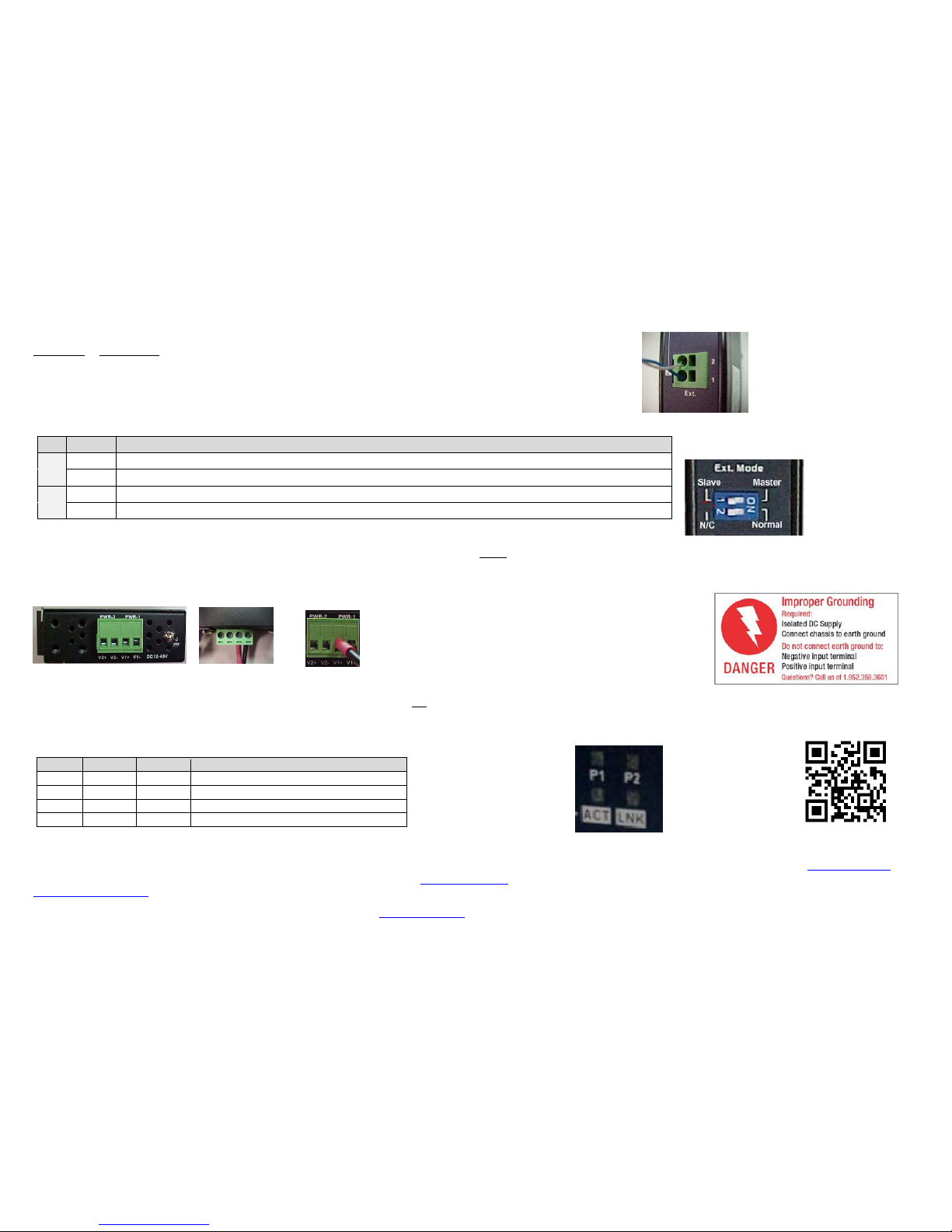
100Mbps Extension (Ext.) Port Terminal Bloc k
Pin Number Assignment * (the “+” and “-” signs represent the polarity of the wires that make up each wire pair)
1 D1+
2 D1-
DIP Switch Functions
The Ext. Mode DIP Switch settings are described below. Note: Both Master and Slave must be set to "Normal". Set the PC/switch side device to "Master" and set the IP camera/other device side to "Slave."
#
Position
Setting
1
ON
Master Mode: Puts device in Master Mode (PC or switch side - user selectable).
OFF
Slave Mode: Puts device in Slave Mode (IP camera side - user selectable).
2*
ON
Normal Mode: Allows user to configure Master Mode or Slave Mode based on DIP switch #1 settings. This is the default setting.
OFF
N/C Mode: Not configurable – default operation should be “Normal” mode. Select Master mode or Slave mode using DIP switch 1.
Terminal Block (PWR-2 and PWR-1) Wiring
The IPOTW1052-111-LRT requires 12-48 VDC. Note: make all connections before applying power. Caution: Before applying power, insert the screw terminal connectors into the Extender and verify all connections.
Make DIP switch changes before applying power.
Step 1: The Extender supports dual redundant power supplies which are connected via the 4-pin terminal block. Insert the negative and positive wires into the V- and V+ terminals, respectively.
Step 2: To keep the DC wires from pulling loose, use a small flat-blade screwdriver to tighten the wire-clamp screws on the front of the terminal block connector.
Grounding
Required for proper grounding: Isolated DC Supply. Connect chassis to earth ground. Do not connect earth ground to: Negative input terminal. Positive input terminal.
LED Descriptions
After installing the device and connecting cables, the green power LED should light. The LEDs are show n an d described below.
LED
Color
Status
Description
P1
Green
On
DC Power Module 1 activated.
P2
Green
On
DC Power Module 2 activated.
LINK
Green
On
Ethernet Extender Port is linked.
ACT
Amber
On
Transmitting data over Ethernet Extender port.
Product Documentation: To access the User Guide, firmware, datasheet or other documentation for your product, enter your model number: IPOTW1052-111-LRT in the “Search” box at www.transition.com.
For more information contact Transition Networks at: 800-526-9267 or visit us online: at www.transition.com. 24-Hour Tech Support: 1-800-260-1312, INTL: +1-952-358-3601, Email:
techsupport@transition.com.
 Loading...