

Page 1
Minneapolis, MN 55344 USA
CAUTION: RJ connectors are NOT INTENDED FOR CONNECTION TO THE
PUBLIC TELEPHONE NETWORK. Failure to observe this caution could result in
damage to the public telephone network.
Compliance Information
UL Listed
C-UL Listed (Canada)
CISPR/EN55022 Class A
FCC Regulations
This equipment has been tested and found to comply with the limits for a class A digital device, pursuant
to part 15 of the FCC rules. These limits are designed to provide reasonable protection against harmful
interference when the equipment is operated in a commercial environment. This equipment generates,
uses, and can radiate radio frequency energy and, if not installed and used in accordance with the
instruction manual, may cause harmful interference to radio communications. Operation of this
equipment in a residential area is likely to cause harmful interference, in which case the user will be
required to correct the interference at the user’s own expense.
Canadian Regulations
This digital apparatus does not exceed the Class A limits for radio noise for digital apparatus set out on
the radio interference regulations of the Canadian Department of Communications.
Copyright Restrictions
© 1999 TRANSITION Networks.
All rights reserved. No part of this work may be reproduced or used in any form or by any means –
graphic, electronic, or mechanical – without written permission from TRANSITION Networks.
Trademark Notice
All registered trademarks and trademarks are the property of their respective owners. 33105.A
Der Anschluss dieses Gerätes an ein öffentlickes Telekommunikationsnetz in den EG-Mitgliedstaaten
verstösst gegen die jeweligen einzelstaatlichen Gesetze zur Anwendung der Richtlinie 91/263/EWG zur
Angleichung der Rechtsvorschriften der Mitgliedstaaten über Telekommunikationsendeinrichtungen
einschliesslich der gegenseitigen Anerkennung ihrer Konformität.
MEDIA CONVERTER TECHNICAL SPECIFICATIONS
Standards IEEE 802.5, 802.5t
Delay 400ns round trip
Case dimensions 4.7" x 3.0" x 1.0" (119mm x 76mm x 25mm)
Shipping Weight 3 lbs (0.9 kg)
Environment Temperature: 0-40°C (32° to 104° F )
Humidity 10-90%, non condensing
Altitude 0-10,000 feet
Maximum number
media converters in series: 2
Warranty Five years
Status LEDs:
Power Supply Requirements Replace power supply with only the equivalent
input rating (see below) and output rating (regulated 9VDC at 0.5 A).
TN PN Requirement Location
3525 240 volts, 50 hertz United Kingdom
3525 230 volts, 50 hertz Europe
3518 120 volts, 60 hertz USA/Canada/Mexico
3514 100 volts, 50-60 hertz Japan
3525 240 volts, 50 hertz Australia
NOTE: This product also can be powered by the Transition Networks E-MCR series media
converter rack.
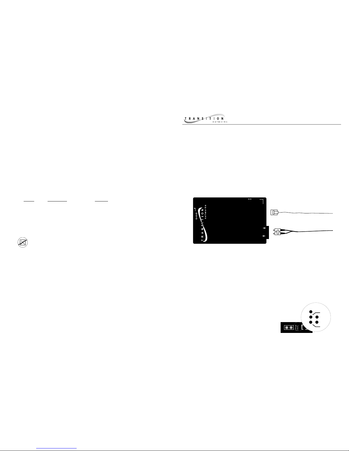
HSTR-CF-01(SC)
Provides an RJ-45 twisted pair
100BASE-TX connector and an RX
(receive) and TX (transmit) SC
100BASE-FX connector to 1300 nm
multimode fiber-optic cable.
HSTR-CF-01(SM)
Provides an RJ-45 twisted pair
100BASE-TX connector and an RX
(receive) and TX (transmit) SC
100BASE-FX connector to 1300 nm
singlemode fiber-optic cable.
Power Illuminated green LED indicates connection to external AC power.
SDF Signal Detect/Fiber: Steady green LED indicates fiber port is
connected to device.
SDC Signal Detect/Copper: Steady green LED indicates
RJ-45 port is connected to device.
RXC Receive/Copper: Flashing green LED
indicates packets are seen on RJ-45
port.
RXF Receive/Fiber: Flashing green LED
indicates packets are seen on fiber port.
High-Speed Token Ring Copper/Fiber
Media Converter
HSTR-CF-01(SC), HSTR-CF-01(SM)
USER’S GUIDE
The TRANSITION Networks High-Speed Token Ring copper-to-fiber media
converters connect either unshielded or shielded High-Speed Token Ring
twisted-pair copper cable to High-Speed Token Ring multimode fiber-optic
cable (HSTR-CF-01(SC)) OR to High-Speed Token Ring singlemode fiber-
optic cable (HSTR-CF-01(SM)).
High Speed Token Ring
Media Converter
UTP/STP
Fiber
HSTR-CF-01(SC)
9V DC Input
Station Lobe
UTP/STP Copper
1300 nm Fiber
RX
TX
Fiber
UTP/STP
Power
RXC
RXF
SDF
SDC
Power
RXC
RXF
SDF
SDC
Page 2
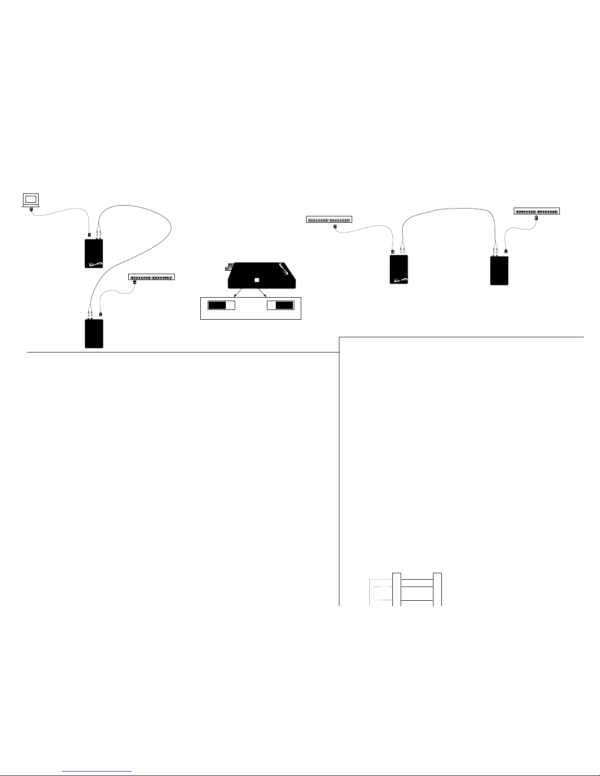
Switch
Switch
Switch
100 meters
2 kilometers - multimode
20 kilometers - singlemode
100 meters
100 meters
2 kilometers - multimode
20 kilometers - singlemode
100 meters
Switch Settings and Cable Requirements
Station: Selected when connecting
media converter to terminal device.
Lobe: Selected when connecting
media converter to switch.
1. Is the power LED on the media converter illuminated?
NO
• Is the power adapter the proper type of voltage and cycle frequency for AC outlet?
• Is the power adapter properly installed in the media converter and in the outlet?
• Contact Technical Support at (800) 260-1312/ (800) LAN-WANS.
YES
• Proceed to step 2.
2. Is the Copper SDC Link LED illuminated?
NO
• Check UTP cables for proper connection and switch position. (See above.)
• Contact Technical Support at (800) 260-1312/ (800) LAN-WANS.
YES
• Proceed to step 3.
3. Is the fiber SDF Link LED illuminated?
NO
• Check fiber cables for proper connection.
• Verify that TX and RX cables on media converter are connected to RX and TX ports,
respectively, on the other device.
• Refer to Tech Tips available at: http://www.transition.com
• Contact Technical Support at (800) 260-1312/ (800) LAN-WANS.
YES
• Contact Technical Support at (800) 260-1312/ (800) LAN-WANS.
Troubleshooting the Media Converter
Installation Notes
The physical characteristics of the media cable must meet or exceed IEEE 802.5t
specifications.
Token Ring Cable Specifications
Copper Cable Specifications
Category 5 wire or better is required. Either shielded twisted pair (STP) or unshielded
twisted pair (UTP) can be used. DO NOT USE FLAT OR SILVER SATIN WIRE.
Category 5:
Gauge 24 to 22 AWG
Attenuation 22 dB/100’ @ 100 MHz
Differential Characteristic Impedance 100 Ω±15%
Maximum Cable Distance: 100 meters (330 feet)
• Be certain that the switch is set correctly for site installation.
• Install unit with power supply unit provided. (Output 9 VDC regulated, 500 mA).
• Install no more than two (2) media converters in series.
HSTR-CF-01
Station
Lobe
TR-CF-01
Fiber Cable Specifications
MULTIMODE
Fiber-optic Cable Recommended: 62.5 / 125 µm multimode fiber
*Optional: 100 / 140 µm multimode fiber
85 / 125 µm multimode fiber
50 / 125 µm multimode fiber
Fiber-optic Transmitter Power: min: -19.0 dBm max: -14.0 dBm
Fiber-optic Receiver Sensitivity: min: -32.5 dBm max: -14.0 dBm
Wavelength: 1300nM
Bit error rate: ≤10
-9
Maximum Cable Distance: 2 kilometers
SINGLEMODE
Fiber-optic Cable Recommended: 9 µm singlemode fiber
Wavelength: 1300nM
Bit error rate: ≤10
-9
Fiber-optic Transmitter Power: min: -19.0 dBm max: -14.0 dBm
Fiber-optic Receiver Sensitivity: min: -32.5 dBm max: -8.0 dBm
Maximum Cable Distance: 20 kilometers
3
4
5
Twisted
Pair #1
Twisted
Pair #2
Straight Through Cable
3
4
5
Switch
NOTE: Use small flatblade screwdriver
or similar device to set recessed switch.
Refer to label on top of media converter
for switch settings.
Twisted pair connection requires two active pairs
configured as straight through. The two active
pairs in a Token Ring network are pins 4 & 5 and
pins 3 & 6. Use only dedicated wire pairs (such
as blue/white & white/blue, orange/white &
 Loading...