

Transition Networks FBRM1xxx-1xx, BFFG1xxx-1xx, FBRM1xxx-1 Series, BFFG1xxx-1 Series Quick Reference Manual
Page 1
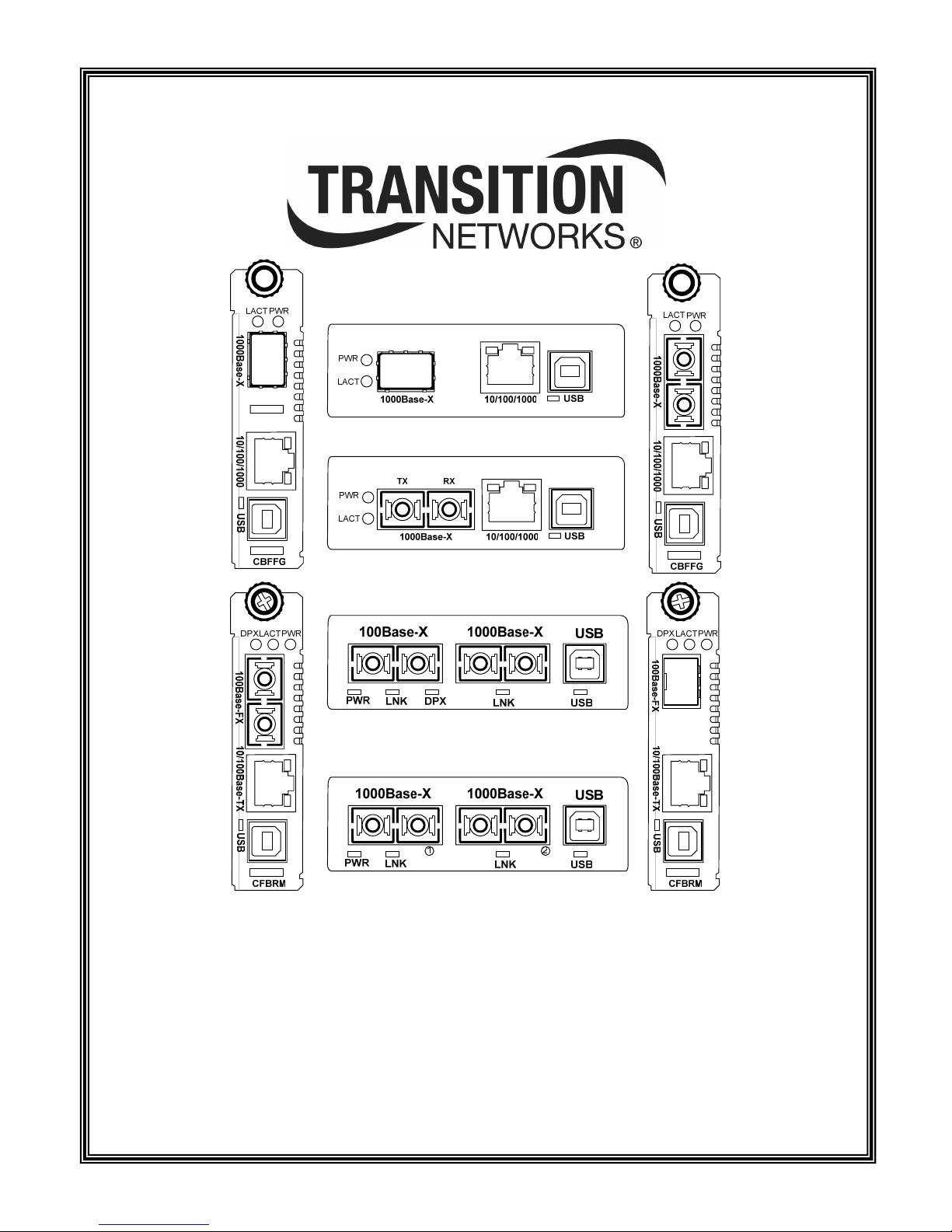
FBRM1xxx-1xx & BFFG1xxx-1xx
Media Converter
Quick Reference Guide
33378.C
Page 2

Table of contents
SHIPPING BOX CONTENTS ...................................................................................................................................3
USB DRIVER INSTALLATION ...............................................................................................................................3
INSTALLING USB DRIVER ...........................................................................................................................................3
DEFAULT USERNAME, PASSWORD, AND IP CONFIGURATION .......................................................................................3
Default user name and password............................................................................................................................3
Default IP configuration.........................................................................................................................................3
HARDWARE INSTALLATION ...............................................................................................................................3
INSTALLING A FBRM/BFFG CHASSIS MODULE ..........................................................................................................3
OAM setup peer management.................................................................................................................................3
INSTALLING A FBRM/BFFG STANDALONE MODULE ..................................................................................................4
SETTING IP NETWORK CONFIGURATION.......................................................................................................4
USB CLI METHOD ......................................................................................................................................................4
POINT SYSTEM CHASSIS AGENT (MMU) METHOD WEB-BASED...................................................................................4
TELNET METHOD.........................................................................................................................................................4
DIRECTLY TO FBRM/BFFG METHOD (WEB-BASED)......................................................................................................4
SETTING USERNAME AND PASSWORD.............................................................................................................4
UPGRADING FIRMWARE.......................................................................................................................................5
XMODEM METHOD ......................................................................................................................................................5
TFTP METHOD ............................................................................................................................................................5
OAM METHOD ............................................................................................................................................................5
OAM CONFIGURATION..........................................................................................................................................5
USB CLI method .....................................................................................................................................................5
Telnet method..........................................................................................................................................................5
IP based (directly to the FBRM/BFFG converter) method.....................................................................................5
Point System chassis agent (MMU) method web-based..........................................................................................6
24-Hour Technical Support: 1-800-260-1312 International: 00-1-952-941-7600 2
Page 3

Introduction
This quick start guide presents information and instructions about the
FBRM/BFFG media converter. The topics are as follows:
• Shipping box contents
• Installing the hardware and USB driver
o Installing USB driver
o Default username and password and
o Default IP configuration
o Chassis card model
o Standalone model
• Setting IP network configuration
• Setting the username and password
• Upgrading firmware
• Setting up OAM
For the full version of the FBRM/BFFG manual, #33345, visit the
website @ www.transition.com
Shipping box contents
• FBRM/BFFG converter (chassis or standalone model)
• Quick reference guide
• Power supply (standalone model only)
Default username, password, and IP configuration
Default user name and password
The FBRM/BFFG comes from the factory with the following default
usernames and passwords.
• USB CLI/Telnet: root, root
• IP interface: private
Default IP configuration
The FBRM/BFFG comes from the factory with the following default IP
configuration.
• IP address: 192.168.1.1
• Subnet Mask: 255.255.255.0
• Gateway: 192.168.1.2
Hardware installation
IMPORTANT
The CFBRM/CBFFG media-converter product family IS NOT compatible with the CPSMM-200 and
CPSMM-210 MGMT modules when they are used in a cascaded application. The CFBRM/CBFFG can
be installed in the “master” chassis with the CPSMM-200 MGMT module, but they cannot be
installed in a cascaded chassis that employees a CPSMM-210 MGMT module.
Alternatively, the CFBRM/CBFFG can be used with the CPSMM120 MGMT module, which does not
support chassis cascading.
USB driver installation
Installing USB driver
The driver installation instructions are for Windows XP. Installing the
drivers using Windows 2000 is similar, but not necessarily identical to
this XP procedure.
Note: The following USB drivers are available at www.transition.com;
also available at www.ftdichip.com
2003, Win 2002, Win ME/98, Mac OS X, 9, 8, Linux.
1. Extract the driver and place it in an accessible folder on the local
drive.
2. Plug the FBRM/BFFG converter into the PC’s USB port to bring up
the “found new hardware” wizard dialog box.
3. Select RADIO button, “No, not this time.
4. Click the NEXT button and follow the instruction in the dialog
boxes to complete the USB driver installation.
After drive installation:
5. Configure the COM port.
6. Set up the terminal emulator:
o Bits per second: 57600
o Data bits: 8
o Parity: none
o Stop bit: 1
o Flow Control none
: WinXP64, Win Server
Installing a FBRM/BFFG chassis module
1. Locate an empty slot in the Point System chassis.
2. (Proper grounding for ESD) grasp the edges of the card by its front
panel.
3. Carefully insert the card into the slot, aligning it with the slot
guides.
4. Firmly seat the card against the chassis back panel.
5. Push IN and ROTATE the panel-fastener screw to secure the card.
6. To set up the FBRM/BFFG for operation use the chassis
management module (MMU) via a Web browser.
OAM setup peer management
Note: By default, OAM is enabled on the fiber port.
1. Connect a fiber cable from the active local device (chassis) to the
passive remote device. The active local device manages its passive
remote peer. The relationship between the active local device and its
passive remote peer is established via OAM automatically.
2. Once OAM is established, all configuration changes to the remote
device can be done via the chassis agent.
24-Hour Technical Support: 1-800-260-1312 International: 00-1-952-941-7600 3
Page 4

Installing a FBRM/BFFG standalone module
Note: By default, OAM is enabled on the fiber port.
1. Install the FBRM/BFFG converter’s provided external power supply
to power up the device.
2. Connect the FBRM/BFFG converter to the PC/Laptop via the USB
or Ethernet port.
3. Configure the FBRM/BFFG converter via the USB CLI or the Web,
using the Default IP address.
Note: If you change the default IP via Web-based configuration, the
connection will be lost; therefore, reconnect using the new IP
address.
Setting IP network configuration
The IP network configuration can be assigned manually or gotten via
DHCP (Dynamic Host Configuration Protocol), using the following
methods:
• USB CLI
• Chassis agent (MMU)
• Telnet
• IP-based (Web)
USB CLI method
To set the IP configuration via the CLI, do the following:
1. Connect the FBRM/BFFG converter to the computer via the USB
port.
2. Activate the terminal emulator software to launch the emulator
screen.
3. Press the ENTER key to bring up the “password” prompt.
4. Enter the password and then the login (default is “root” in both
cases) to bring up the device console> prompt
5. To access the commands list, at the console> prompt type help or ?
6. Press the ENTER key to show the “commands.”
Note: Type “help set <command>” to display the format for setting any
command.
DHCP method:
Note: A DHCP server must be on the network and accessible.
1. To set the IP via DHCP, at the console> prompt type set dhcp=enable
2. Press the ENTER key.
3. Type reboot.
4. Press the ENTER key to reboot, enabling DHCP.
Manual method:
1. To set the IP, at the console> prompt type set ip=nnn.nnn.nnn.nnn
2. Press the ENTER key to establish the new IP address.
3. Repeat Steps 1 and 2 for setting the subnet mask and gateway, if
required.
Point System chassis agent (MMU) method Web-based
To set the IP configuration via the MMU, do the following:
1. Open a Web browser.
2. At the URL, type the IP address (nnn.nnn.nnn.nnn) of the chassis
MMU.
3. Press the ENTER key to launch the MMU interface.
4. Enter a password (default is private).
5. Click the LOGIN button to launch the main menu.
6. Click on the VIEW button to display the cards in the chassis.
7. Locate the desired FBRM/BFFG card.
8. Click the VIEW button to show local switch parameters
a. If you want to set the IP, subnet mask, and gateway manually
type the value in the appropriate box.
b. If you want to the set the IP configuration dynamically, a
DHCP server most be on the network and accessible, then
enable DHCP and reboot the module.
9. Click the SAVE/EXECUTE button to save the changes. (Changes
take effect immediately.)
Telnet method
To configure IP via telnet, do the following:
1. At the command line type: Telnet
2. Press the SPACE BAR then
3. Type the FBRM/BFFG IP address (nnn.nnn.nnn.nnn).
4. Press the OK button to launch the Telnet login screen.
5. Login (default login and password is root)
Note: The interface for Telnet is the same as the USB CLI.
Directly to FBRM/BFFG method (web-based)
To configure IP via the Web, do the following:
1. Open a Web browser.
2. At the URL, type the default IP address (nnn.nnn.nnn.nnn) of the
FBRM/BFFG converter.
3. Press the ENTER key to launch the device interface.
4. Enter a password (default is private).
5. Click the LOGIN button to launch the converter main menu.
6. Click Local System Configuration VIEW button to display the
device configuration screen (IP, subnet mask, and gateway are
configured on this screen).
Setting username and password
Note: The username and password can only be changed via the USB
CLI (command line interface).
To set the username and password do the following:
1. At the console prompt type set username=“new name” (include the quotes)
2. Press the ENTER key and the new username will appear at the console
prompt.
3. Press the ENTER key.
4. Type set password=“new password” (include the quotes).
5. Press the ENTER key and the new password will appear at the console
prompt.
6. Press the ENTER key.
7. Type reboot.
8. Press the ENTER key to reboot and set the new username and
password.
24-Hour Technical Support: 1-800-260-1312 International: 00-1-952-941-7600 4
Page 5

Upgrading firmware
The firmware image on the converter can be upgraded by these methods:
• XModem
• TFTP protocol
• OAM
When enabled, OAM is done automatically when the active peer detects
that its remotely managed peer is running on an older firmware version.
TFTP and XModem are initiated by the user. All firmware upgrades are
done by the “bootloader.”
Note: The bootloader recognizes incompatible FBRM/BFFG BIN files
when upgrading. Since there are different FBRM/BFFG board
types, it is possible to download the wrong BIN file. When the
converter receives an incorrect bin file through TFTP or
XMODEM, the following message will appear on the screen:
Bootloader: Hardware and BIN file mismatch,
upgrade aborted.
Xmodem method
To upgrade the firmware via Xmodem do the following:
1. At the console prompt> type xmodemupgrade
2. Press the ENTER key and an upgrade decision Yes/No prompt will
appear.
Note: If you select “Y,” the memory of the targeted device will be
erased.
3. Type “Y” at the prompt.
4. Press the ENTER key to launch the firmware download process.
5. Upon request, choose the ‘send file’ option from Hyperterminal
with ‘XModem’ as the protocol (a time out is activated for this
step). After the download, the bootloader verifies the CRC of the
file and resets itself to start the user application.
TFTP method
The device can be upgraded remotely using TFTP. A valid IP address,
subnet, gateway, tftp server IP address, and filename must be configured
before starting the upgrade process.
TFTP can be started in the following ways:
• ‘tftpupgrade’ command at the CLI
• On the web using Æ “Local System Configuration’ Æ ‘TFTP upgrade’
[perform(1)]
• Using SNMP, set on ‘sfbrm100SysTFTPCmd’ to ‘1’ (perform)
After initiating the command, the system resets to start the bootloader;
then the tftp upgrade will start. After successful upgrading the firmware,
the application will start up.
OAM method
OAM firmware upgrades are done from the active local device to the
passive remote device. This occurs when the active local device finds that
its remote peer has a firmware revision different from its own. The active
local device sends a bootloader command to its remote peer. When the
firmware upgrade on the remote peer is completed, it performs a reboot to
activate the new firmware—no user intervention is required. (Active and
passive peer relationships are established automatically when OAM is
enabled.)
OAM configuration
The OAM can be configured via:
• USB CLI
• Telnet
• IP based (directly to the FBRM/BFFG converter)
• Point System chassis agent (MMU)
USB CLI method
To configure OAM via CLI, do the following:
1. Connect the FBRM/BFFG converter to the computer via the USB
port.
2. Activate the terminal emulator software to launch the emulator
screen.
3. Press the ENTER key to bring up the “password” prompt.
4. Enter the password and then the login (default is “root” in both
cases) to bring up the device console> prompt
5. To access the commands list, at the console> prompt type help or ?
6. Press the ENTER key to show the “commands.”
7. At the console> prompt type command ifoam
8. Press the ENTER key to show the OAM commands.
9. For command format help, at the console> prompt type help ifoam
10. Press the ENTER to display the command format for setting OAM
parameters.
Formatting a command:
11. For example, to make port 2 OAM active, at the console> prompt type
ifoam port=2 oammode=active
12. Press the ENTER key to establish the change.
View the change:
13. At the console> prompt type show ifoam
14. Press the ENTER key to display current status.
Telnet method
To configure OAM via telnet, do the following:
6. At the command line type: Telnet
7. Press the SPACE BAR then type the device IP address
(nnn.nnn.nnn.nnn).
8. Press the OK button to launch the Telnet login screen.
9. Login (default login and password is root)
Note: The interface for Telnet is the same as the USB CLI.
IP based (directly to the FBRM/BFFG converter) method
To configure OAM via IP, do the following:
1. Open a Web browser
2. At the URL, type the IP address (nnn.nnn.nnn.nnn) of the
FBRM/BFFG converter.
3. Press the ENTER key to launch the device interface.
4. Enter a password (default is private).
5. Click the LOGIN button to launch the converter main menu.
6. Click on a PORT button to display the port configuration screen
(OAM is configured on this screen).
7. Click the SAVE/EXECUTE button to save the changes.
24-Hour Technical Support: 1-800-260-1312 International: 00-1-952-941-7600 5
Page 6

Point System chassis agent (MMU) method web-based
To configure OAM via the MMU, do the following:
1. Open a Web browser.
2. At the URL, type the IP address (nnn.nnn.nnn.nnn) of the chassis
MMU.
3. Press the ENTER key to launch the MMU interface.
4. Enter a password (default is private).
5. Click the LOGIN button to launch the main menu.
6. Click on a VIEW button to display the modules in the chassis.
7. Locate the desired FBRM/BFFG converter card.
8. Click the VIEW button to show the FBRM/BFFG local switch
display.
9. To enable OAM, click on the desired port to display its
configuration parameters (OAM configuration is done on this
screen).
10. Click the SAVE/EXECUTE button to save the changes.
24-Hour Technical Support: 1-800-260-1312 International: 00-1-952-941-7600 6
 Loading...