

Page 1
Transition Networks EO2Pxx4052-111 Quick Start Guide
EO2Pxx4052-111 Quick Start Guide
Introduction
Transition Networks’ EO2Pxx4052-111 Ethernet Extenders With PoE+ (EO2P) allow up to
1000Mb data communication and deliver SELV (Safety Extra Low Voltage) power over twisted
pair wiring to a connected IP device. Each installation requires a pair of these devices, one
Local Unit at the network source and one Remote Unit near the connected PoE device.
See the full EO2P User Guide for Product Numbers, Applications, Configuration Examples, Features, Package Contents,
Port Descriptions, Web Config pages, Technical Specs, Warranty and Compliance info, Messages, and Troubleshooting.
Installation
Note: See the EO2P User Guide for important Cautions and Warnings including Operating temperature, Air Flow,
Mechanical Loading, Circuit Overloading, etc.
Mounting Install the EO2P units indoors (or in an appropriately rated enclosure).
Securely mount the EO2P units. Do not support the EO2P units by the attached cables.
Use any of the Mounting options to mount the EO2P unit. See the User Guide for options.
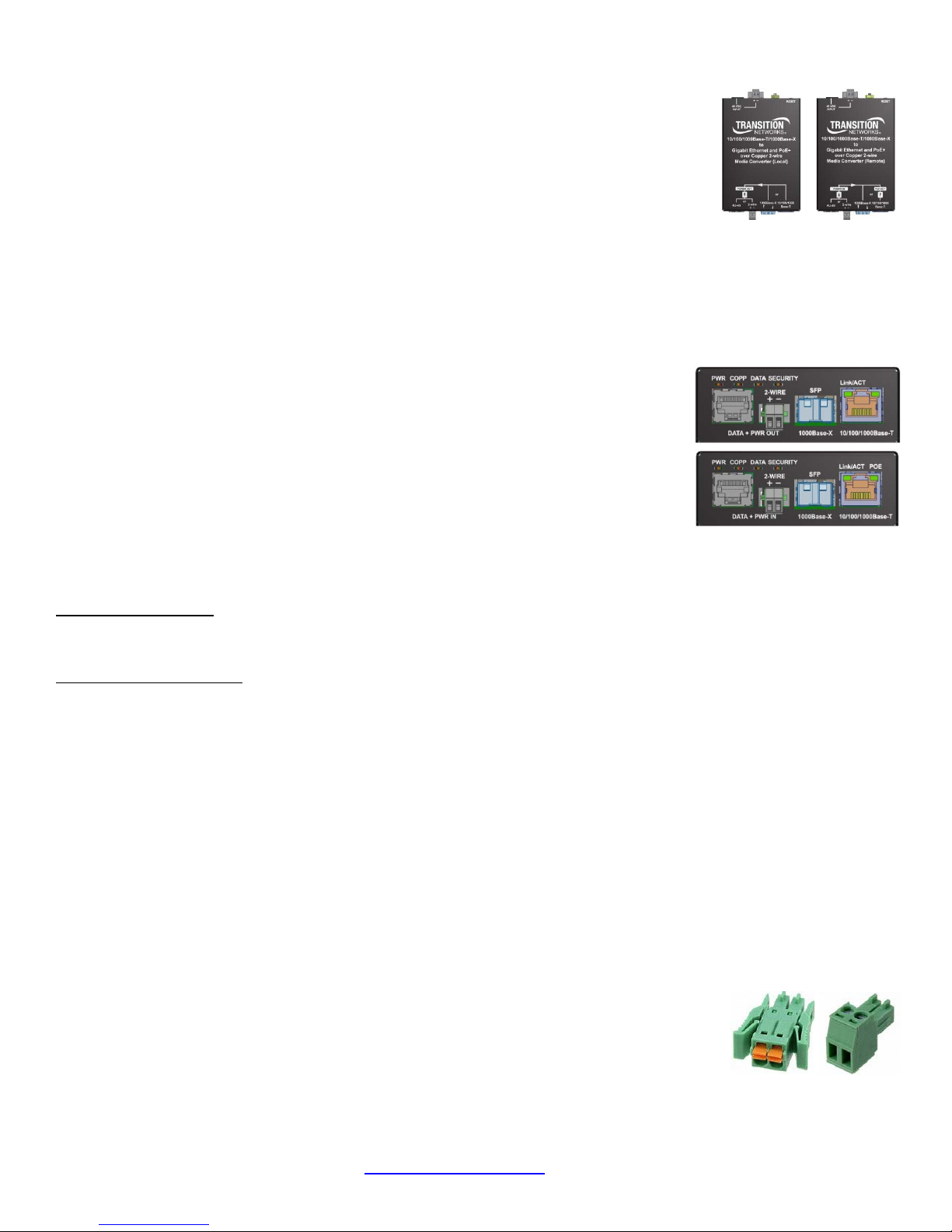
Front Panels: Local Device (top right) Remote Device (bottom right):
Network Connections
Network Connection: The EO2PSE4052-111 offers a Combo (Shared) port for connecting to either copper or fiber
network equipment. In terms of copper versus fiber port selection / priority, only one port can be active at any given
time; by default the SFP port takes precedence over the copper port (configurable on the Ethernet Web GUI page).
SFP / Fiber Connection: The EO2P lets you install an SFP optic of your choice in order to make a fiber connection. The
EO2P has a single SFP port. The SFP port supports any MSA compliant 100/1000Base-X SFP module. For temperatures
above +50 C, industrial SFP modules (+85 C) must be used. Install and connect Single-strand or Two-strand Fiber cable.
Ethernet Cable Connection: Connect the EO2PSE4052-111 RJ45 Ethernet jack to the EO2PD, camera or other network
equipment using a standard Ethernet cable.
Power over Ethernet: Using the PoE option, the EO2PSE4052-111 can automatically enable delivery of up to 30 watts of
power to the EO2PD4052-11. The EO2PD4052-111 can supply up to 25.5 Watts of PoE (IEEE 802.3at-class) power to a
connected powered device. Warning: Do not plug a network cable into the Power Out or Power In RJ-45 jacks.
Remote: Local Power Source: DIN or TB (48V@45W). Remote POE-PSE: IEEE 802.3at - Class 4. 802.3at PSE Power Out: 30
W at Remote Unit; 25.5W Power at PD.
Extension Data and Power Connection
Install the RJ-45 Copper Cable: 1. Locate a 10/100/1000Base-TX compliant copper cable with male RJ-45 connectors
installed at both ends. 2. Connect the RJ-45 connector at one end of the cable to the EO2P 10/100/1000Base-RJ-45 port.
3. Connect the RJ-45 connector at the other end of the cable to the 10/100/1000Base-RJ-45 port on the device (camera,
WAP, etc.) that you wish to connect and power.
RJ45 Connection: Install an RJ45 connectorized cable between Local unit DATA + PWR OUT and the Remote Uni t DATA +
PWR IN RJ45 connectors. The cable can be fully- or partially pinned. See the User Guide for Cable configurations.
2-Wire Connection (Local to Remote Unit): Connect the EO2PSE4052-111 unit’s 2-wire
connector to the 2-wire cable. The 2-wire connector should only be used to connect a Local
unit to a Remote Unit. The EO2Pxx4052-111 is not compatible with other equipment such as
analog video amplifiers.
33705 Rev. B https://www.transition.com Page 1 of 2
Page 2
Transition Networks EO2Pxx4052-111 Quick Start Guide
Powering the EO2P
The 90W Power supply 25148 is an option for powering the Local PSE unit,
and is optional for use with the Remote PD Unit. The PWR LED blinks to
indicate the presence of power to the EO2Pxx4052-111 (for indoor use only).
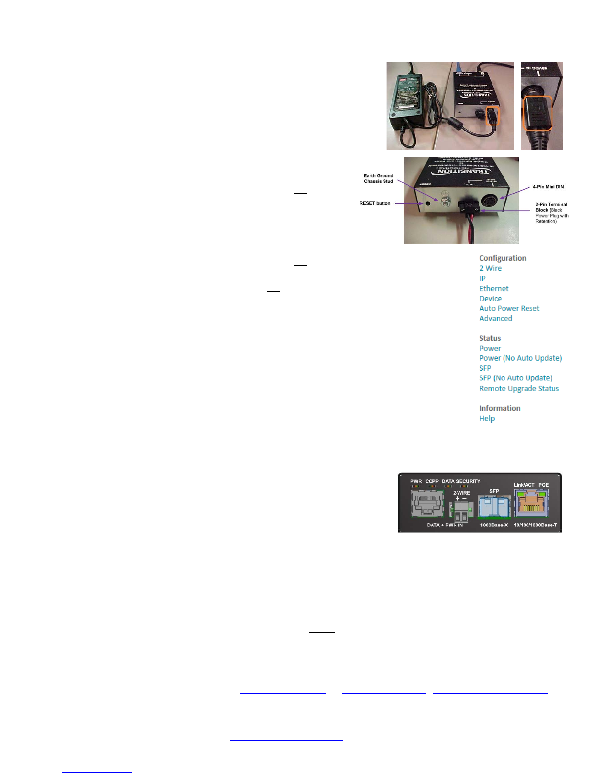
48 VDC IN Options: The two 48 VDC input options are the 4-Pin Mini DIN and
the 2-Pin Terminal Block (right).
power supply cable from the 48VDC IN 4-Pin Mini DIN connection.
Local PSE (EO2PSE4052-111) Power Input Options:
1. A 4-Pin mini DIN with the designated AC to DC adapter OR
2. 2-Pin Terminal Block connectors for +48 VDC power source that
must meet IEEE 802.3 af/at isolation requirements of 1500VAC or
2250 VDC. Note: this must be +48 VDC IN.
Remote PD (EO2PD4052-111) Power Input Options:
1. A 4-Pin mini DIN with the designated AC to DC adapter OR
2. 2-Pin Terminal Block connectors for +48 VDC power source that must meet IEEE 802.3 af/at
isolation requirements of 1500VAC or 2250 VDC. OR
3. PoE input power to the Remote Unit from the Local unit via the 2-wire cable.
Grounding: An earth ground chassis stud is provided on the back panel. Note that bonding the
earth ground to the chassis stud will improve circuit protection.
Note: use the flat-topped grip to remove the
Software Operation
Web GUI Configuration: The Web GUI lets you access the Login page and subsequent
configuration pages (2 Wire, IP, Ethernet, Device, Auto Power Reset, and Advanced) and Status
(Power, SFP, and Remote Upgrade Status) pages. The default IP address is 192.168.0.1 (Local) and
192.168.0.2 (Remote). The default password is admin.
We recommend you change your password
immediately.
Status LEDs
PWR: Power and bootloader status: Power applied: Green - ON.
Firmware update in progress: Orange – ON and/or BLINK.
COPP: Power delivery (Local unit) or sourcing (Remote Unit) status and/or fault: see the
User Guide for Local vs. Remote Unit LED descriptions.
DATA – 2-wire data link; Linked: Green – BLINK.
SECURITY: Secure mode, pairing mode, and key/config state: Not secure: OFF. Secure: Green – ON.
In Config mode: Green – Slow BLINK. In Pairing mode: Green – Fast BLINK. Received key & finished config: Green – 3 BLINKS.
Link/ACT - 1GE TP or Fiber port: 1000Mbps: Green - ON link, BLINK activity. 100Mbps: Green and Yellow - ON link, BLINK activity.
10Mbps: Yellow - ON link, BLINK activity.
POE – Power Over Ethernet status (Remote PD Unit only): No PD detected: OFF. Power applied: Green – ON. Detect fault: Yellow –
ON: Fault or Remote is not a PoE device. Classification fault: Yellow - BLINK.
RESET button: If doing security Pairing for 2-wire encryption, do this before final deployment of Local PSE and Remote PD Units in
the field. See User Guide for details; the RESET button performs other functions, and you could lose Remote PD Unit connection.
Transition Networks 10900 Red Circle Drive * Minnetonka, MN 55343 USA * Tel: +1.952.941.7600 *
* Toll Free: 800.526.9267 * Fax: 952.941.2322 * sales@transition.com * * info@transition.com * techsupport@transition.com
33705 Rev. B https://www.transition.com Page 2 of 2
*
 Loading...