

Page 1
MEDIA CONVERTER TECHNICAL SPECIFICATIONS
Standards IEEE 802.3
Case dimensions 3.9" x 3.0" x 1.0" (99mm x 76mm x 25mm)
Environment Temperature: 0-50°C (32° to 122° F )
Humidity 10-90%, non condensing
Altitude 0-10,000 feet
MTBF E-CX-TBT-04 48,000 hours
E-CX-FRL-04 47,000 hours
Warranty 5 years
Ethernet™
networks
TRANSITION
E-CX-TBT-04
10Base2 to 10BaseT
Media Converter
9V DC Input
10Base2
Thin Coax
UTP
10BaseT
Ethernet™
networks
TRANSITION
E-CX-FRL-04
Fiber
10BaseFL to 10Base2
Media Converter
9V DC Input
10Base2
RX TX
Thin Coax
CAUTION: RJ connectors are NOT INTENDED FOR CONNECTION TO THE
PUBLIC TELEPHONE NETWORK. Failure to observe this caution could result in
damage to the public telephone network.
Compliance Information
UL Listed
C-UL Listed (Canada)
CISPR/EN55022 Class A
FCC Regulations
This equipment has been tested and found to comply with the limits for a class A digital device, pursuant
to part 15 of the FCC rules. These limits are designed to provide reasonable protection against harmful
interference when the equipment is operated in a commercial environment. This equipment generates,
uses, and can radiate radio frequency energy and, if not installed and used in accordance with the
instruction manual, may cause harmful interference to radio communications. Operation of this
equipment in a residential area is likely to cause harmful interference, in which case the user will be
required to correct the interference at the user’s own expense.
Canadian Regulations
This digital apparatus does not exceed the Class A limits for radio noise for digital apparatus set out on
the radio interference regulations of the Canadian Department of Communications.
European Regulations
Warning
This is a Class A product. In a domestic environment this product may cause radio interference in which
case the user may be required to take adequate measures.
Copyright Restrictions
© 1996, 1999 TRANSITION Networks.
All rights reserved. No part of this work may be reproduced or used in any form or by any means –
graphic, electronic, or mechanical – without written permission from TRANSITION Networks.
Trademark Notice
All registered trademarks and trademarks are the property of their respective owners. 7380.E
Der Anschluss dieses Gerätes an ein öffentlickes Telekommunikationsnetz in den EG-Mitgliedstaaten
verstösst gegen die jeweligen einzelstaatlichen Gesetze zur Anwendung der Richtlinie 91/263/EWG zur
Angleichung der Rechtsvorschriften der Mitgliedstaaten über Telekommunikationsendeinrichtungen
einschliesslich der gegenseitigen Anerkennung ihrer Konformität.
Power Supply Requirements Replace power supply with only the equivalent input
rating (see below) and output rating (regulated 9VDC at 0.5 A).
TN PN Requirement Location
3517 240 volts, 50 hertz United Kingdom
3516 230 volts, 50 hertz Europe
3518 120 volts, 60 hertz USA/Canada/Mexico
3514 100 volts, 50-60 hertz Japan
3515 240 volts, 50 hertz Australia
E-CX-TBT-04
E-CX-FRL-04
Minneapolis, MN 55344 USA
10BASE-2/10BASE-T
10BASE-2/10BASE-FL
Media Converters
E-CX-TBT-04
E-CX-FRL-04
USER’S GUIDE
Page 2
6
1
10BASE-FL CABLE SPECIFICATIONS
MULTIMODE
Fiber Optic Cable Recommended: 62.5 / 125 µm multimode fiber
Optional: 100 / 140 µm multimode fiber
85 / 125 µm multimode fiber
50 / 125 µm multimode fiber
Fiber Optic Transmitter Power: Average power: -15.0 dBm
Peak power: -12.0 dBm ±1dBm
Fiber Optic Receiver Sensitivity: Average sensitivity: -27.4 dBm
Bit error rate: ≤10
-10
Maximum Cable Distance: 2000 meters
SINGLEMODE
Fiber Optic Cable Recommended: 9/125 micron single mode fiber
Fiber Optic Transmitter Power: Typical transmit power: -22.5dBm
Best case transmit power: -18.5dBm
Worst case transmit power: -28.5dBm
Fiber Optic Receiver Power: Best case fiber sensitivity: -35dBm
Worst case fiber sensitivity: -30dBm
Bit error rate: ≤10
-10
Maximum Cable Distance: 5,000 meters- 20,000 meters
10BASE-2 CABLE SPECIFICATIONS
Cable type: Stranded Coaxial RG58
Impedance: 50 Ω @ 10 MHz
Mutual Capacitance: 24 pF/ft ±20% @ 10 MHz
Maximum Cable Distance: 185 meters (610 feet)
Maximum number connections:30
Minimum distance/connection: 0.5 meters (1.6 feet)
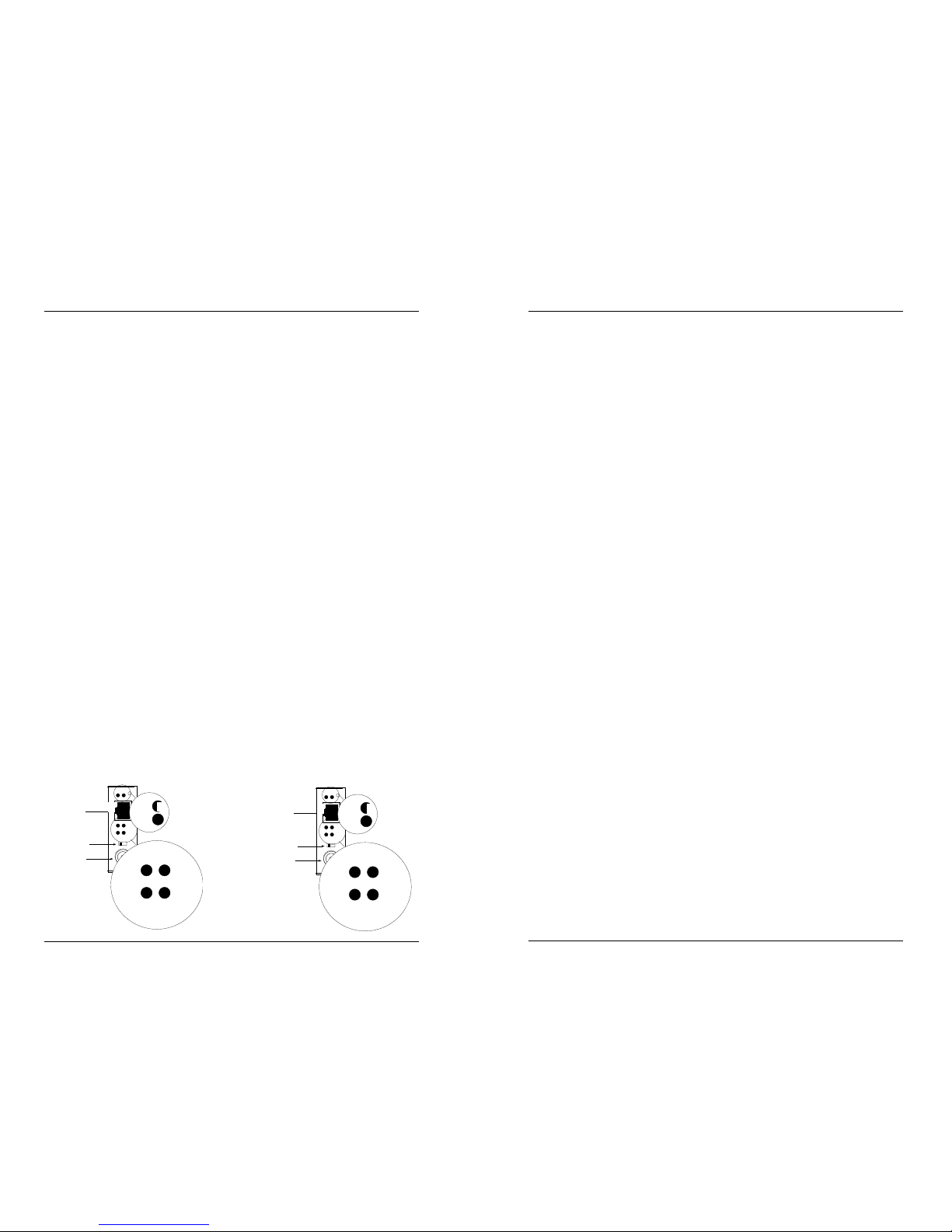
MEDIA CONVERTER CONNECTORS,
SWITCHES and INDICATORS
ETHERNET CABLE SPECIFICATIONS
The physical characteristics of the media cable must meet or exceed IEEE 802.3
10BASE-T, 10BASE-2, and/or 10BASE-FL specifications.
Maximum number of media converters in series: 2
Power
0
Jab
Coll.
CX RX
10Base2
10BaseT
RX
Link
50
Power
Coll.
Jab
CX RX
RJ-45
Connector
BNC
Connector
RX
Link
Coax Config
Switch
CONNECTORS
10BASE-T RJ-45 connector
10BASE-2 BNC connector
10BASE-FL TX, RX ST type connectors (SMA type
available upon request)
INDICATORS
Power Steady green LED indicates normal
operation.
(CX, FL, RJ) RX (Receive) Flashing green LED indicates port
is receiving data.
(CX, FL) Link Steady green LED indicates port is receiving
link signal.
Coll(ision) Flashing green LED indicates port is in a
collision state. NOTE: Steady illumination
indicates an excessive number of collisions
are occurring on the port.
Jab(ber) Steady green LED indicates a jabber
condition.
SWITCH
Coax Config(uration) Sets internal 10BASE-2 terminator to either
50 ohms or 0 ohms.
E-CX-TBT-04
10BASE-T CABLE SPECIFICATIONS
Category 3 wire or better is required; category 5 wire is recommended. Either shielded
twisted pair (STP) or unshielded twisted pair (UTP) can be used. DO NOT USE FLAT
OR SILVER SATIN WIRE.
Category 3:
Gauge 24 to 22 AWG
Attenuation 28 dB/1000’ @ 10 MHz
Differential Characteristic Impedance 100 Ω ±10% @ 10 MHz
Category 5:
Gauge 24 to 22 AWG
Attenuation 20 dB/1000’ @ 10 MHz
Differential Characteristic Impedance 100 Ω ±10% @ 10 MHz
Maximum Cable Distance: 100 meters (330 feet)
o
o
Power
0
Jab
Coll.
CX RX
10Base2
10BaseT
RX
Link
50
Power
Coll.
Jab
CX RX
RJ-45
Connector
BNC
Connector
RX
Link
Coax Config
Switch
o
o
E-CX-FRL-04
Page 3

2
5
NOTE: The media converter supports 10mbps speeds only.
ALL MEDIA CONVERTERS:
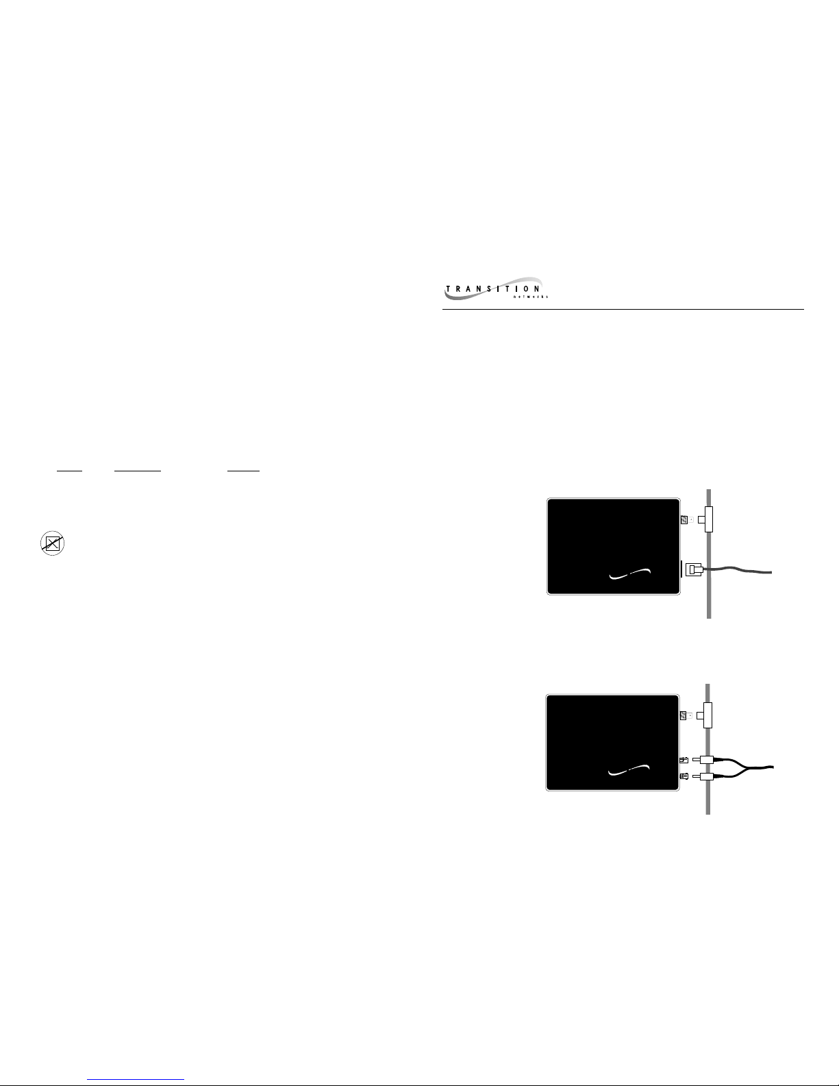
• Install the media converter with the power supply provided.
(Output 9 VDC regulated, 500 mA).
• Connect the power supply cable to the media converter BEFORE
connecting the power supply cable to the AC outlet.
• Do NOT connect more than two media converters in series.
10BASE-T CONNECTIONS
• Be certain that the 10BASE-T cable is configured correctly for site
installation (straight through or crossover), as shown on the next
page. NOTE: An RJ-45 telephone cable is reverse-wired, which is
NOT the same as a crossover pinout.
10BASE-2 CONNECTIONS
• Ground EACH coax segment to earth ground at one end.
• Set coax configuration switch:
Use 50 ohm switch position when connecting the end of a coax
segment DIRECTLY to the media converter's BNC port.
Use 0 ohm switch position when connecting to the middle or in
line of a thin coax segment. (For this position a BNC "T" must be
connected to the media converter's BNC port).
10BASE-FL CONNECTIONS
NOTE: Fiber connections are full duplex.
• Verify that the fiber products to be connected are 10BASE-FL or
FOIRL compliant. NOTE: Fiber ports on TRANSITION Networks
fiber media converters conform to 10BASE-FL or FOIRL but NOT
to 10BaseFB or FDDI.
• 62.5/125 micron duplex fiber cable is recommended.
• The maximum loss for the fiber cable should not exceed 13 dBm.
MEDIA CONVERTER INSTALLATION NOTES
1. Is the power LED on the media converter illuminated?
NO
• Is the power adapter the proper type of voltage and cycle
frequency for your AC outlet? NOTE: Refer to the “Power
Supply Requirements” on the back page.
• Is the power adapter properly installed in the media converter
and in the outlet?
• Contact Technical Support: (800) 260-1312/(800) LAN-WANS.
YES
• Proceed to step 2.
2. Is the Link LED illuminated?
NO
10BASE-T
• Check UTP cables for proper connection and pin assignment
shown in diagram on previous page.
• Is the Link Switch on the media convertor set to ON?
• Contact Technical Support: (800) 260-1312/(800) LAN-WANS.
10BASE-2
• Check coax cables for proper connection.
•
Check coax cable for opens or shorts. Check and/or replace each
BNC “T” connector on the segment, making sure each “T” is
attached firmly.
• Verify that coax cables on media converter are terminated
properly at both ends. NOTE: In a coax thinnet installation,
the first and last device in a daisy-chain are terminated.
• Verify that each 10BASE-2 segment is grounded to earth
ground.
• Contact Technical Support: (800) 260-1312/(800) LAN-WANS.
10BASE-FL
• Check fiber cables for proper connection.
• Verify that TX and RX cables on media converter are
connected to RX and TX ports, respectively, on the other
10BASE-FL device.
• Refer to Tech Tips available at:
http://www.transition.com
• Contact Technical Support: (800) 260-1312/(800) LAN-WANS.
YES
• Contact Technical Support: (800) 260-1312/(800) LAN-WANS.
MEDIA CONVERTER TROUBLESHOOTING
SUGGESTIONS
If a Media Converter fails, ask the following questions:
Page 4

50 ohm terminator
50 ohm terminator
GND
Coax Config Switch
Set to 0
straight-through
crossover
OR
TX TX TX RX
OR
OR
Coax Config Switch
Set to 50
50 ohm terminator
Coax Config Switch
Set to 0
50 ohm terminator
GND
50 ohm terminator
GND
MEDIA CONVERTERS in the NETWORK
E-CX-FRL-04
Setting the Coax Configuration Switch:
Set switch position to 50 ohms when connecting the end
of a thin coax segment DIRECTLY to the media converter's
BNC port. (NOTE: The minimum coax cable length must
be 0.5 meters.)
Set switch position to 0 ohms when connecting to the
middle or in line of a thin coax segment. (NOTE: For this
position a BNC "T" must be connected to the media
converter's BNC port).
TRANSITION Networks media converters provide media
connections to and from 10BASE-T, 10BASE-2, and 10BASE-FL.
E-CX-TBT and E-CX-FRL both require the coax configuration switch to be set and the coax segment to be grounded.
E-CX-TBT-04
Configuring 10BASE-T Straight Through/Crossover
Cable Assembly
The two active pairs in a 10BASE-T network are pins 1 & 2
and pins 3 & 6. Use only dedicated wire pairs (such as
blue/white & white/blue,
orange/white & white/orange) for
the active pins.
Cable connections between a
hub and the media converter
must be configured as straight
through. Cable connections
between the media converter and
a terminal, transceiver or NIC
E-CX-TBT requires straight through/crossover 10BASE-T cable configuration.
Twisted
Pair #1
Twisted
Pair #2
Crossover Cable
Connectors for like devices
Twisted
Pair #1
Twisted
Pair #2
Straight Through Cable
Connectors for unlike devices
 Loading...