


User’s Guide
E-100BTX-FX-05
Stand-Alone Media Converter
•Fast Ethernet
•Copper to Fiber
•100Base-TX to 100Base-FX
•Extended Temperature
Transition Networks E-100BTX-FX-05 Fast Ethernet media converter connects 100BaseTX shielded or unshielded twisted-pair
copper cable to 100Base-FX fiber-optic cable. The E-100BTX-FX-05 series of media converters include both standard temperature models (listed below) and extended temperature model.
Standard Temperature Models: 0°C to 50°C (32°F to 122°F)
Part Number |
Port One - Copper |
Port Two - Duplex Fiber-Optic |
|
100Base-TX |
100Base-FX |
E-100BTX-FX-05 |
RJ-45 |
ST, 1300 nm multimode |
|
100 m (328 ft)* |
2 km (1.2 miles)* |
|
|
|
E-100BTX-FX-05(SC) |
RJ-45 |
SC, 1300 nm multimode |
|
100 m (328 ft)* |
2 km (1.2 miles)* |
|
|
|
E-100BTX-FX-05(LC) |
RJ-45 |
LC, 1300 nm multimode |
|
100 m (328 ft)* |
2 km (1.2 miles)* |
|
|
|
E-100BTX-FX-05(MT) |
RJ-45 |
MT-RJ, 1300 nm multimode |
|
100 m (328 ft)* |
2 km (1.2 miles)* |
|
|
|
E-100BTX-FX-05(SM) |
RJ-45 |
SC, 1310 nm single mode |
|
100 m (328 ft)* |
20 km (12.4 miles)* |
|
|
|
E-100BTX-FX-05(SMLC) |
RJ-45 |
LC, 1310 nm single mode |
|
100 m (328 ft)* |
20 km (12.4 miles)* |
E-100BTX-FX-05(LH) |
RJ-45 |
SC, 1310 nm single mode |
|
100 m (328 ft)* |
40 km (24.9 miles)* |
|
|
|
E-100BTX-FX-05(XL) |
RJ-45 |
SC, 1310 nm single mode |
|
100 m (328 ft)* |
60 km (37.3 miles)* |
|
|
|
E-100BTX-FX-05(LW) |
RJ-45 |
SC, 1550 nm single mode |
|
100 m (328 ft)* |
80 km (49.7 miles)* |
|
|
|
E-100BTX-FX-05(XLW) |
RJ-45 |
SC, 1550 nm single mode |
|
100 m (328 ft)* |
120 km (74.56 miles)* |
|
|
|
*Typical maximum cable distance. Actual distance is dependent upon the physical characteristics of the network installation.
Installation . . . . . . . . . . . . . . . . |
. .3 |
Operation . . . . . . . . . . . . . . . . . . |
.5 |
Cable Specifications . . . . . . . . . . |
.7 |
Technical Specifications . . . . . . . |
.9 |
Troubleshooting . . . . . . . . . . . . . |
10 |
Contact Us . . . . . . . . . . . . . . . . . |
11 |
Compliance Information . . . . . . . |
12 |
E-100BTX-FX-05
The media converters with the “HT” extension in the part number can be used in an extended temperature environment from -25°C to 65°C (-13°F to 149°F).
Part Number |
Port One - Copper |
Port Two - Duplex Fiber-Optic |
|
|
100Base-TX |
100Base-FX |
|
E-100BTX-FX-05(HT) |
RJ-45 |
ST, 1300 nm multimode |
|
|
100 m (328 ft)* |
2 km (1.2 miles)* |
|
|
|
|
|
E-100BTX-FX-05(SCHT) |
RJ-45 |
SC, 1300 nm multimode |
|
|
100 m (328 ft)* |
2 km (1.2 miles)* |
|
|
|
|
|
E-100BTX-FX-05(SMHT) |
RJ-45 |
SC, 1310 nm single mode |
|
|
100 m (328 ft)* |
20 km (12.4 miles)* |
|
|
|
|
|
E-100BTX-FX-05(LHHT) |
RJ-45 |
SC, 1310 nm single mode |
|
|
100 m (328 ft)* |
40 km (24.9 miles)* |
|
|
|
|
|
E-100BTX-FX-05(XLHT) |
RJ-45 |
SC, 1310 nm single mode |
|
|
100 m (328 ft)* |
60 km (37.3 miles)* |
|
|
|
|
|
E-100BTX-FX-05(LWHT) |
RJ-45 |
SC, 1550 nm single mode |
|
|
100 m (328 ft)* |
80 km (49.7 miles)* |
|
E-100BTX-FX-05(100HT)** |
RJ-45 |
SC, 1310Tx/1550Rx nm single |
|
|
100 m (328 ft)* |
mode |
|
|
|
20 km (12.4 miles)* |
|
|
|
|
|
E-100BTX-FX-05(101HT)** |
RJ-45 |
SC, 1550Tx/1310Rx nm single |
|
|
100 m (328 ft)* |
mode |
|
|
|
20 km (12.4 miles)* |
|
|
|
|
|
**E-100BTX-FX-05(100/101HT) are installed in pairs.
Accessories sold separately
Part Number |
Description |
SPS-1872-SA |
Optional External Power Supply; 18-72VDC Stand-Alone Wide- |
|
Input; Output: 12.6VDC, 1.0 A |
|
|
SPS-1872-CC |
Optional External Power Supply; 18-72VDC Piggy-Back Wide- |
|
Input; Output: 12.6VDC, 1.0 A |
|
|
E-MCR-04 |
12-Slot Media Converter Rack (includes universal internal power |
|
supply) 17 x 15 x 5 in. (432 x 381 x 127 mm) |
|
|
WMBL |
Optional Wall Mount Brackets; 4.0 in. (102 mm) |
WMBV |
Optional Vertical Mount Bracket; 5.0 in. (127 mm) |
|
|
WMBD |
Optional DIN Rail Mount Bracket; 5.0 in. (127 mm) |
|
|
WMBD-FS |
Optional DIN Rail Mount Bracket (flat, small); 3.1in. (79 mm) |
Installation
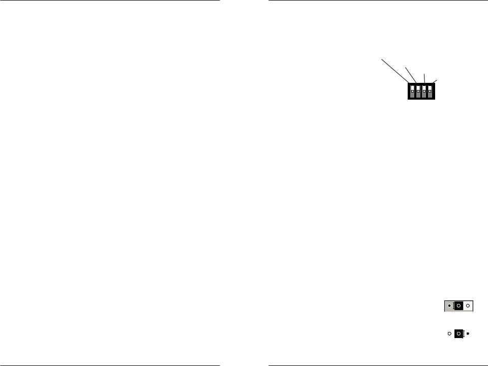
CAUTION: Wear a grounding device and observe electrostatic discharge precautions when setting the 4-position switch and jumper. Failure to observe this caution could result in damage or failure of the media converter.
4-position switch
•The 4-position switch is located on the side of the media converter. Use a small flat-blade screwdriver or a similar device to set the recessed switches.
Auto-Negotiation (up=Enable)
Pause (up=Enable)
Link Pass-Through (up=Enable)
Far End Fault
(up=Enable)
1. Auto-Negotiation |
1 2 3 4 |
|
up |
Enables Auto-Negotiation for the copper connection. |
|
down |
Disables Auto-Negotiation for the copper connection. |
|
2.Pause Control up Enabled down Disabled
3.Link Pass-Through up Enabled down Disabled
4.Far-End Fault up Enabled
down Disabled
AutoCross™ Jumper
The AutoCross feature allows either straight-through (MDI) or crossover (MDI-X) cables to be used when connecting to devices such as hubs, transceivers, or network interface cards (NICs). AutoCross determines the characteristics of the cable connection and automatically configures the unit to link up, regardless of the cable configuration.
NOTE: AutoCross is enabled by default, the recommended state.
The jumper is located on the media converter’s circuit board To set the jumper:
1.Using a small screwdriver, remove the four (4) screws that secure the cover; then remove the cover from the media
converter. |
J3 |
|
|
|
|
|
|
|
|
|
|
|
|||
|
|
|
|
|
|
||
|
|
|
|
|
|
||
2. Locate header J3 on the circuit board; using a small |
Enabled AutoCross |
||||||
needle-nosed pliers move the jumper to the desired |
|
|
|
|
|
|
|
position. (Refer to the drawing to the right.) |
J3 |
|
|
|
|
||
|
|
|
|
||||
3. Carefully replace the cover, and then replace the |
|
|
|
|
|||
|
|
|
|
||||
Disabled AutoCross |
|||||||
four (4) screws to secure the cover to the media |
|||||||
|
|
|
|
|
|
||
converter. |
|
|
|
|
|
|
|
2 |
24-hour Technical Support: 1-800-260-1312 -- International: 00-1-952-941-7600 |
techsupport@transition.com -- Click the “Transition Now” link for a live Web chat. |
3 |

E-100BTX-FX-05
Installation -- Continued
Installing the fiber cable
1.Locate a 100Base-FX compliant fiber cable with male, two-stranded TX to
RX connectors installed at both ends.
2. Connect the fiber cables to the media converter as described:
•Connect the male TX cable connector to the female TX port.
•Connect the male RX cable connector to the female RX port.
3.Connect the fiber cables to the other device (another media converter, hub, etc.) as described:
•Connect the male TX cable connector to the female RX port.
•Connect the male RX cable connector to the female TX port.
Connect fiber cable |
Connect fiber cable |
to media converter |
to other device |
as shown. |
(media converter, |
|
hub, etc.) as shown |
RX |
RX |
TX |
TX |
Installing the copper cable
1.Locate or build 100Base-TX compliant copper cables with male, RJ-45 connectors installed at both ends.
2.Connect the RJ-45 connector at one end of the cable to the RJ-45 port on the media converter.
3.Connect the RJ-45 connector at the other end of the cable to the RJ-45 port on the other device (switch, workstation, etc.).
|
|
|
|
|
|
|
|
RJ-45 port |
RJ-45 port |
||
on the media |
on the other device |
||
converter |
(switch, work station, etc.) |
||
|
|
|
|
Installation -- Continued
Power the media converter
AC
1.Install the power cord barrel connector into the back of the media converter.
2.Connect the power adapter plug into AC power.
3.Verify that the media converter is powered by observing the illuminated LED power indicator light.
DC
Consult user guide 33266 for information on the SPS-1872-xx DC external power supply.
Operation
Status LEDs
Use the status LEDs to monitor the E-100BTX-FX-05 media converter operation in the network.
Power |
(Power) |
On = Connection to external AC power. |
SDF |
(Signal Detect/Fiber) |
On = Fiber link is detected. |
SDC |
(Signal Detect/Copper) |
On = Copper link is detected. |
RXC |
(Receive/Copper) |
Flashing = A signal is being received on |
|
|
the copper link. |
RXF |
(Receive/Fiber) |
Flashing = A signal is being received on |
|
|
the fiber link. |
Auto-Negotiation
When the Auto-Negotiation feature is activated, the media converter configures itself to achieve the best possible mode of operation over a link automatically. The media converter broadcasts its speed (100 Mb/s) and duplex capabilities (either fullor half-duplex) and negotiates the best mode of operation between the two devices.
4 |
24-hour Technical Support: 1-800-260-1312 -- International: 00-1-952-941-7600 |
techsupport@transition.com -- Click the “Transition Now” link for a live Web chat. |
5 |
 Loading...