

Page 1
About the Media Converter:
The Transition Engineering media converter, P/N E-CX-TBT-03 allows the network
manager to interconnect existing Ethernet 10Base2 devices to a newly installed 10Ba
twisted pair type of network.
The media converter has a BNC female coax connection, an RJ-45 twisted pair
connection and an external male coax barrel type jack for an external power supply
The media converter is ideal for installations that have thin coax cable already instal
It lets the network manager daisy chain up to 24 coax devices from the one 10BaseT
twisted pair segment.
The media converter has two external switching functions. The first is for link enable
link disable, this allows the media converter to function with current 10BaseT standa
equipment as well as older 10BaseT devices. The second switch is for termination o
coax line, which is explained in detail in this installation guide.
7090 Shady Oak Road
Eden Prairie, MN 55344 USA
10Base2 to 10BaseT
Media Converter User’s Guide
Model #: E-CX-TBT-03
Manual #: 7343.A 6/94
Case size dimensions: 3.75" x 2.38" x 0.88" (9.5cm X 6.0cm X 2.2cm)
10BaseT
RJ45 Input
External Power
Input Port
Link
Sense
OFF
ON
Ethernet
10BaseT / 10Base2 Adapter
RX
Link
Coax
Config.
1 2 3
Collision
RX
Power
Jabber
E-CX-TBT-03
Rev. Pol.
Collision
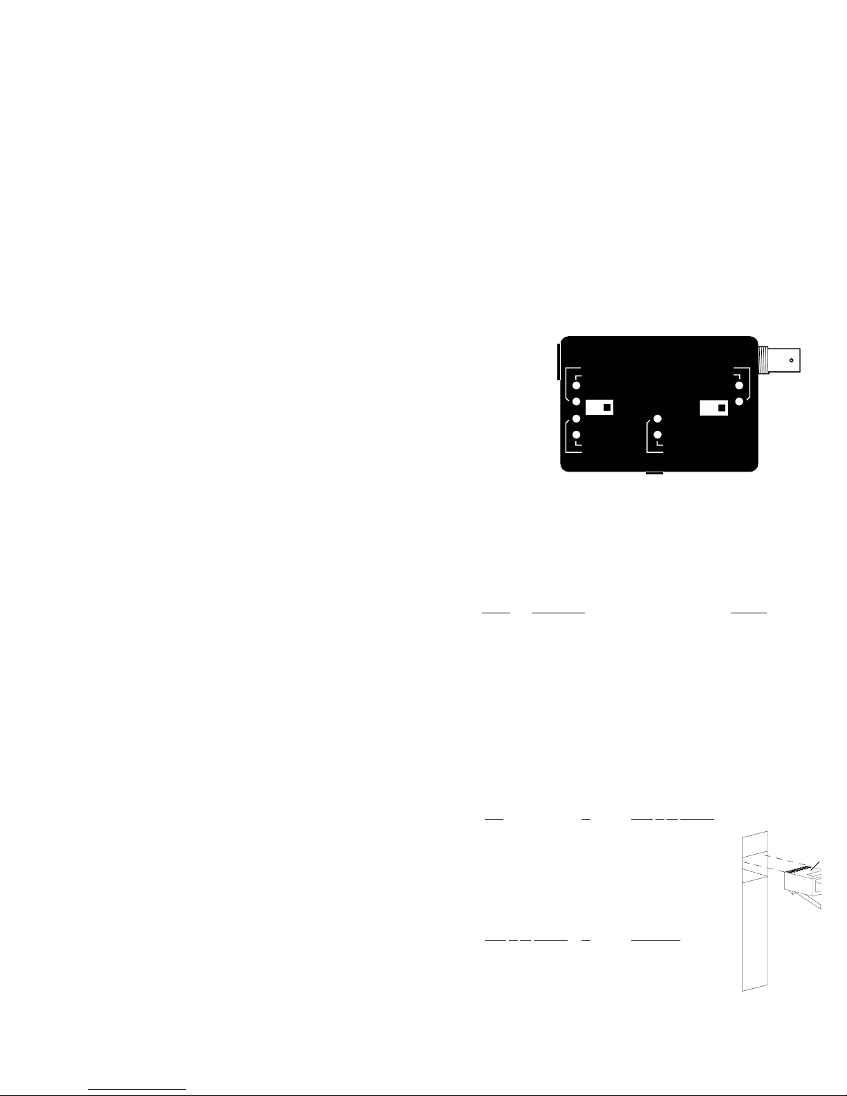
Setting the Link Sense Switch:
The Link Sense switch can be turned ON to enable the Link integrity or it can be turned
OFF to disable the Link integrity. The Link Sense switch is located and marked on the
front of the media converter. (Refer to the picture on the front page of this user’s guide).
(A small regular screw driver is ideal for switching the Link Sense switch ON and OFF).
Link Enable Position (ON): When the Link switch is (ON) or enabled, it sends a Link
pulse through the segment. This pulse is present only for
current 10BaseT devices.
Link Disable Position (OFF): When the Link switch is (OFF) or disabled, the Link
pulses are turned off. In this position the media
converter can communicate with pre-10BaseT devices.
(Check your devices to see if they transmit Link pulses).
Technical Support:
For more information about this product or other Transition Engineering products, call
TE directly or your local Transition Engineering distributor.
Direct TE numbers are listed below:
TE Main Phone Numbers (800) 325-2725 or (612) 941-7600
TE Technical Support Number (800) 260-1312
TE Fax Number (612) 941-2322
TE Bulletin Board (612) 941-9304
FCC Regulations:
Note: This equipment has been tested and found to comply with the limits for a
Class A digital device, pursuant to Part 15 of the FCC Rules. These limits are designed
to provide reasonable protection against harmful interference when the equipment is
operated in a commercial environment. This equipment generates, uses, and can
radiate radio frequency energy and, if not used in accordance with the instruction
manual, may cause harmful interference to radio communications. Operation of this
equipment in a residential area is likely to cause harmful interference in which case
the user will be required to correct the interference at his own cost.
Canadian Regulations:
Note: This digital apparatus does not exceed the Class A limits for radio noise for digital
apparatus set out on the radio interference regulations of the Canadian Department of
Communications.
Trademarks:
Ethernet is a registered trademark of the Xerox Corporation, Inc.
Transition Engineering is a trademark of Transition Engineering, Inc.
Rev 6/94
P/N 7343.A
Power Supply Requirements:
Replace power supply with only the equivalent input rating (refer to the table belo
output rating (regulated 9VDC).
TE PN
Requirement Location
3514 9VDC at 0.55A, 100VAC at 50–60Hz Japan
3515 9VDC at 0.5A, 240VAC at 50Hz Australia
3516 9VDC at 0.5A, 230VAC at 50Hz Europe
3517 9VDC at 0.5A, 240VAC at 50Hz United Kingdom
3518 9VDC at 0.55A, 120VAC at 60Hz USA/Canada/Mexico
RJ-45 Pin Specifications:
Individual wires that make up a straight through twisted pair modular cable
are shown below. Each pair has designated pin connections on an RJ-45 modular
connector. There are only two active pairs in a 10BaseT network, pins 1 & 2 and
3 & 6. Use only dedicated wire pairs (such as blue/white, white/blue, orange/whi
white/orange, etc.).
Hub
to Coax to TP Adapter
RJ-45 Male RJ-45 Male
1 [RX +] - - - - - - - - - - - - - - - - - [TX +]1
2 [RX -] - - - - - - - - - - - - - - - - - - [TX -] 2
3 [TX +] - - - - - - - - - - - - - - - - - -[RX +] 3
6 [TX -] - - - - - - - - - - - - - - - - - - [RX -] 6
The following are the pins for a
crossover cable to
cascade from a 10BaseT Terminal to a Media Converter.
Coax
to TP Adapter to Transceiver
RJ-45 Male RJ-45 Male
1 [TX +] - - - - - - - - - - - - - - - - - -[RX +] 3
2 [TX -] - - - - - - - - - - - - - - - - - - [RX -] 6
3 [RX +] - - - - - - - - - - - - - - - - - [TX +]1
6 [RX -] - - - - - - - - - - - - - - - - - - [TX -] 2
Media Converter Specifications:
- Media Converter Case Dimensions: 3.75" x 2.38" x 0.88"
(9.5cm X 6.0cm X 2.2cm)
- Maximum Distance for 10BaseT Segment: 100 meters (330 feet), Level 3 or above
twisted pair cable recommended
- Maximum Distance for Thin Coax Segment: 185 meters (610 feet), Approved Ethernet
cable recommended
- Power Supply: External regulated 9VDC power supply.
- Environment: 0 – 50˚ C, 5% – 90% humidity noncondensing, 0 – 10,000 foot altitude
- Warranty: Two Years
Monitoring the Media Converter's LEDs:
Crossview of t
UTP Cable Co
T
1
8
Crossview of the RJ-45 Port
Main: Power-
Jabber-
UTP Port: Receive (RX)-
Link Status-
Rev. PolarityCollision-
Coax Port: Collision-
Receive (RX)-
Lit green LED indicates normal operation
Flashing red LED indicates Jabber is active
Flashing or lit green LED indicates packet(s) are being received
Lit green LED indicates the unit is receiving Link
pulses from a 10BaseT compliant device. (enable
/disable via external switch)
Lit red LED indicates improper polarity on RX lines
Flashing or lit red LED indicates a collision has occurred
Flashing or lit red LED indicates a collision has occurred
Flashing or lit green LED indicates packet(s) are being received
Setting the Coax Config. Switch:
The first termination (switch position 1), 50 ohms, is used when connecting the end
of a coax segment directly to the media converter's BNC port.
The second termination (switch position 2), NO termination, is used when connecting to
the middle or in line of a thin coax segment. (For this position a BNC "T" must be connected to the media converter's BNC port).
The third termination (switch position 3), 25 ohms, is used when connecting directly to a
workstation or DTE. (For this position a direct connection no longer than six inches
must be used. A BNC M / M adapter is a preferred connection).
 Loading...