

Page 1
FCC Regulations:
NOTE: This equipment has been tested and found to comply with the limits for
a Class A digital device, pursuant to Part 15 of the FCC Rules. These limits are
designed to provide reasonable protection against harmful interference when the
equipment is operated in a commercial environment. This equipment generates,
uses, and can radiate radio frequency energy and, if not used in accordance with
the instruction manual, may cause harmful interference to radio communications.
Operation of this equipment in a residential area is likely to cause harmful
interference in which case the user will be required to correct the interference at
his own cost.
NOTE: This equipment has been tested and found to comply with CISPR Class A
requirements.
Canadian Regulations:
Note: This digital apparatus does not exceed the Class A limits for radio noise for
digital apparatus set out on the radio interference regulations of the Canadian
Department of Communications.
Copyright Restrictions:
© 1994, 1997 TRANSITION Networks.
All rights reserved. No part of this work may be reproduced or used in any form or
by any means- graphic, electronic, or mechanical- without written permission from
TRANSITION Networks.
Trademark Notice:
All registered trademarks and trademarks are the property of their respective owners.
Technical Support:
For more information about this product or other TRANSITION Networks products,
call your local TN distributor or TN directly. The TN numbers listed below:
TN Main Phone Numbers (800) 325-2725 or (612) 941-7600
TN Technical Support Number (800) 260-1312
TN Fax Number (612) 941-2322
TN Bulletin Board (612) 941-9304
Rev 9/94
P/N 7350.B
The Bridge SIC
User’s Guide
Model #: E-BR-SIC
Guide #: 7350.B 9/94
About the Bridge Slide-In Card:
The bridge SIC is a device that segments network traffic by keeping a list of service nod
on SIC connector (THE WORKGROUP) side of the bridge. It re-transmits a message fro
a node on the workgroup side only if it is destined for a node on the AUI connector (TH
BACKBONE) side of the bridge.
The bridge SIC assumes that the AUI connection is one network and the SIC connectio
is another network. The bridge only learns the addresses of the users on the workgroup
side (256 addresses max.). When a packet is sent from one user on the workgroup side
to another user on the workgroup side the packet is not forwarded to the backbone.
When a packet is seen on the backbone side that is not addressed to a member of the
workgroup the packet is not forwarded to the workgroup side of the bridge. This filteri
function for regular traffic and broadcast packets can be disabled for either direction w
the configuration switches listed on the next page.
Dimensions: 5.50” x 3.00” x 1.00”
(13.97cm x 7.62cm x 2.54cm)
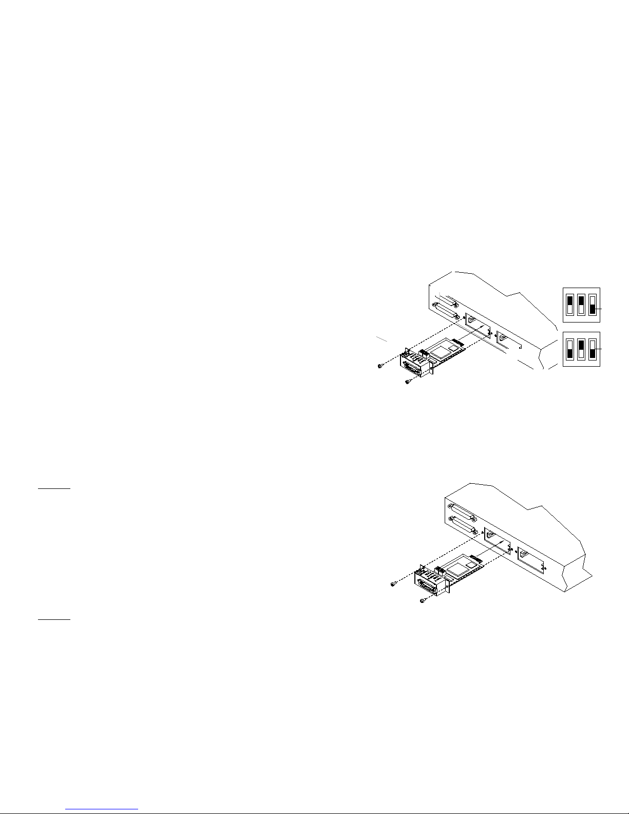
Figure 1 Crossview of the Bridge SIC
SW2
SW3
Reset
Button
SW2
1 2 3
OFF
SW3
1 2 3
OFF
Pre
dow
(OF
Switch Setting Examp
N/A
Setting Banks SW2 and SW3:
On the bridge SIC there are two banks of switches. As shown in Figure 1, the banks are
labeled SW2 and SW3 on the printed circuit board. Each bank has 3 two-position
switches. The function of each bank is described below.
Bank SW2
• When switch 1 is set to the OFF position, packet filtering from the workgroup
to the backbone is disabled. In other words all packets from the workgroup are sent
onto the backbone. When switch 1 set to the ON position, only packets that are NOT
addressed to a known member of the workgroup are passed to the backbone.
• When switch 2 is set to the OFF position, packet filtering from the backbone to
the workgroup is disabled. In other words, all packets from the backbone are sent to
the workgroup. When switch 2 is set to the ON position, only packets addressed to
known members of the workgroup are passed from the backbone to the workgroup.
• When switch 3 is set to the OFF position, all broadcast packets are passed from
the backbone to the workgroup. When switch 3 is set to the ON position, broadcast
packets from the backbone are NOT passed to the workgroup.
Bank SW3
• When switch 1 is set to the OFF position, all broadcast packets are passed from
the workgroup on to the backbone. When in the ON position broadcast packets from
the workgroup are NOT passed to the backbone.
• When switch 2 is set to the OFF position, packets will not be passed in either direction
for 15 seconds after RESET while the bridge learns the source addresses on the
workgroup LAN. When switch 2 is set to the ON position, packets are passed in both
directions immediately after RESET, workgroup source addresses are still learned.
• Switch 3 is not used.
Reset Button:
A reset button is located on the front of the SIC. The reset button is used to reset
lock-up or malfunction conditions. After the button is pressed, the bridge will
automatically recycle and resume normal operation.
Installing the Bridge SIC :
Carefully install and secure the Bridge SIC into the SIC slot. This procedure should be
done in an ESD safe environment, such as touching the unit frame or using a grounded
strap.
Monitoring the LEDs:
WTraffic Green LED is lit when there is traffic on the workgroup.
WCol Red LED is lit when there is a collision on the workgroup.
B o W Green LED is lit when a packet is passed from the workgroup to
the backbone.
BTraffic Green LED is lit when there is traffic on the backbone.
BCol Red LED is lit when there is a collision on the backbone.
B k W Green LED is lit when a packet is passed from the backbone to the
workgroup.
Bridge SIC Specifications:
•`Dimensions: 5.50” x 3.00” x 1.00”
(13.97cm x 7.62cm x 2.54cm)
• Environment:
Temperature 32˚ - 122˚ F (0 - 50˚ C)
Humidity 5% - 90% non-condensing
Altitude 0 - 10,000 feet (maximum)
• Limited Warranty: Five Years
• AUI Connector: DB-15 with slide lock
• Maximum Cable Distance: 165 feet (50 meters)
Figure 2 Installing the Bridge SIC
Important:
You can hot swap
(install and remove)
the Bridge SIC with
the unit power ON.
 Loading...