


Multichannel Media Converter
33214.A
METTF10xx, MFETF10xx

COMPLIANCE INFORMATION
UL Listed
C-UL Listed (Canada)
CISPR/EN55022 Class A
FCC Regulations
This equipment has been tested and found to comply with the limits for a class A digital device, pursuant to part 15 of
the FCC rules. These limits are designed to provide reasonable protection against harmful interference when the
equipment is operated in a commercial environment. This equipment generates, uses, and can radiate radio frequency
energy and, if not installed and used in accordance with the instruction manual, may cause harmful interference to
radio communications. Operation of this equipment in a residential area is likely to cause harmful interference, in
which case the user will be required to correct the interference at the user’s own expense.
Canadian Regulations
This digital apparatus does not exceed the Class A limits for radio noise for digital apparatus set out on the radio
interference regulations of the Canadian Department of Communications.
Le présent appareil numérique n'émet pas de bruits radioélectriques dépassant les limites applicables aux appareils
numériques de la class A prescrites dans le Règlement sur le brouillage radioélectrique édicté par le ministère des
Communications du Canada.
European Regulations
Warning
This is a Class A product. In a domestic environment this product may cause radio interference in which case the user
may be required to take adequate measures.
Achtung !
Dieses ist ein Gerät der Funkstörgrenzwertklasse A. In Wohnbereichen können bei Betrieb dieses Gerätes
Rundfunkstörungen auftreten, in weichen Fällen der Benutzer für entsprechende Gegenmaßnahmen werantwortlich ist.
Attention !
Ceci est un produit de Classe A. Dans un environment domestique, ce produit risque de créer des interférences
radioélectriques, il appartiendra alors à l’utilsateur de prende les measures spécifiques appropriées
VCCI Class 1 Compliance
This equipment is in the 1st Class category
(information equipment to be used in commercial
and/or industrial areas) and conforms to the standards
set by the Voluntary Control Council For Interference
by Data Processing Equipment and Electronic Office
Machines aimed at preventing radio interference in
commercial and/or industrial areas. When used in a
residential area or in an adjacent area thereto,
interference may be caused to radio and TV
receivers, etc. Read the instructions for correct
handling.
Trademark Notice
All registered trademarks and trademarks are the property of their respective owners.
Copyright Restrictions
© 2001 TRANSITION Networks.
All rights reserved. No part of this work may be reproduced or used in any form or by any means – graphic, electronic,
or mechanical – without written permission from TRANSITION Networks.
Printed in the U.S.A.
CAUTION: RJ CONNECTORS ARE NOT INTENDED FOR CONNECTION TO THE PUBLIC
TELEPHONE NETWORK. Failure to observe this caution could result in damage to the public telephone
network.
Der Anschluss dieses Gerätes an ein öffentlickes Telekommunikationsnetz in den EG-Mitgliedstaaten
verstösst gegen die jeweligen einzelstaatlichen Gesetze zur Anwendung der Richtlinie 91/263/EWG zur
Angleichung der Rechtsvorschriften der Mitgliedstaaten über Telekommunikationsendeinrichtungen einschliesslich
der gegenseitigen Anerkennung ihrer Konformität.

Table of Contents
1. INTRODUCTION . . . . . . . . . . . . . . . . . . . . . . . . . . . . . . . . .1.1
1.1 Multichannel Media Converter Models . . . . . . . . . . . . 1.2
1.2 Media Converter Channels . . . . . . . . . . . . . . . . . . . . . 1.2
1.3 Channel Switches . . . . . . . . . . . . . . . . . . . . . . . . . . . . 1.3
1.4 Reset Button . . . . . . . . . . . . . . . . . . . . . . . . . . . . . . . . 1.3
1.5 AC Power Supply Module/Optional Redundant AC Power
Supply Module . . . . . . . . . . . . . . . . . . . . . . . . . . . . . . 1.3
1.6 Multichannel Media Converter Management Module . 1.4
1.7 Multiport Management Software at Remote NMS . . . . 1.5
2. INSTALLATION . . . . . . . . . . . . . . . . . . . . . . . . . . . . . . . . . . .2.1
2.1 Preparing the Site . . . . . . . . . . . . . . . . . . . . . . . . . . . . . 2.2
2.2 Unpacking METTF10xx, MFETF10xx Equipment . . . . . 2.3
2.3 Installing Optional Redundant Power Supply Module . 2.4
2.3.1 Setting Management Module Jumper .2.4
2.3.2 Installing Power Supply Module . . . . .2.5
2.4 Installing Multichannel Media Converter at Site . . . . . . 2.6
2.4.1 Standard Rack Installation . . . . . . . . .2.6
2.4.2 Table-Top Installation . . . . . . . . . . . . .2.7
2.5 Powering the Multichannel Media Converter . . . . . . . 2.8
2.6 Connecting Channel Ports to Network . . . . . . . . . . . . . 2.9
2.6.1 Setting FDX/HDX Channel Configuration
Switches . . . . . . . . . . . . . . . . . . . . . . . . . . .2.9
2.6.2 Installing Fiber-optic Cable . . . . . . . .2.10
2.6.3 Installing Twisted-Pair Copper Cable 2.11
2.7 Setting Network Management Parameters . . . . . . . . . 2.12
2.8 Connecting to TCP/IP Network Management at Remote
Network Management Station (NMS) . . . . . . . . . . . . . 2.14
2.9 Installing Multiport Management Software at Remote NMS .
. . . . . . . . . . . . . . . . . . . . . . . . . . . . . . . . . . . . . . . . . . 2.15
MULTICHANNEL MEDIA CONVERTER
i

3. OPERATION . . . . . . . . . . . . . . . . . . . . . . . . . . . . . . . . . . . . .3.1
3.1 Using Status LEDs . . . . . . . . . . . . . . . . . . . . . . . . . . . . 3.2
3.2 Using a Terminal Emulator . . . . . . . . . . . . . . . . . . . . . 3.3
3.3 Using Multiport Management Software at Remote NMS 3.6
4 MAINTENANCE . . . . . . . . . . . . . . . . . . . . . . . . . . . . . . . . . .4.1
4.1 Fault Isolation and Recovery . . . . . . . . . . . . . . . . . . . . 4.2
4.2 Hardware Replacement Procedures . . . . . . . . . . . . . . . 4.5
4.2.1 Replacing Management Module . . . . .4.5
4.2.2 Replacing AC Power Supply Module .4.6
APPENDIX . . . . . . . . . . . . . . . . . . . . . . . . . . . . . . . . . . . . . . . . .A.1
Appendix A. Technical Specifications . . . . . . . . . . . . . . . . . . A.1
Appendix B. Cable Specifications . . . . . . . . . . . . . . . . . . . . . B.1
METTF10xx, MFETF10xx
ii

1. INTRODUCTION
The TRANSITION Networks METTF10xx (Ethernet™) and MFETF10xx (Fast
Ethernet
™
) series Multichannel Media Converters connect twisted-pair
copper cable to fiber-optic cable in separate copper-to-fiber media
converter pairs, called channels. The network administrator can select a
Multichannel Media Converter that provides up to six (6) or up to twelve
(12) channels, with either 10BASE-T/10BASE-FL or 100BASE-TX
/100BASE-FX connections and with either ST or SC fiber connectors.
The Multichannel Media Converter can be installed as a standalone unit
or in a standard rack and can be managed at an attached terminal or using
an SNMP application at a remote Network Management Station. Fullduplex or half-duplex network operation, for each channel, is switchselectable or software-selectable.
1.1 Multichannel Media Converter Models .................................1.2
1.2 Media Converter Channels ....................................................1.2
1.3 Channel Switches ..................................................................1.3
1.4 AC Power Supply Module/Optional Redundant AC Power
Supply Module .......................................................................1.3
1.5 Multichannel Media Converter Management Module ...........1.4
1.6 Multiport Management Software at Remote NMS .................1.5
1.1
MULTICHANNEL MEDIA CONVERTER
1.1 Multichannel Media Converter Models
The TRANSITION Networks METTF10xx and MFETF10xx series
Multichannel Media Converters can be selected according to network
requirements:
MFETF1011-120 12-channel 100 Mb/s, multimode fiber, ST
connectors
MFETF1013-120 12-channel 100 Mb/s, multimode fiber, SC
connectors
MFETF1011-060 6-channel 100 Mb/s, multimode fiber, ST
connectors
MFETF1013-060 6-channel 100 Mb/s, multimode fiber, SC
connectors
METTF1011-120 12-channel 10 Mb/s, multimode fiber, ST
connectors
METTF1013-120 12-channel 10 Mb/s, multimode fiber, SC
connectors
METTF1011-060 6-channel 10 Mb/s, multimode fiber, ST
connectors
METTF1013-060 6-channel 10 Mb/s, multimode fiber, SC
connectors
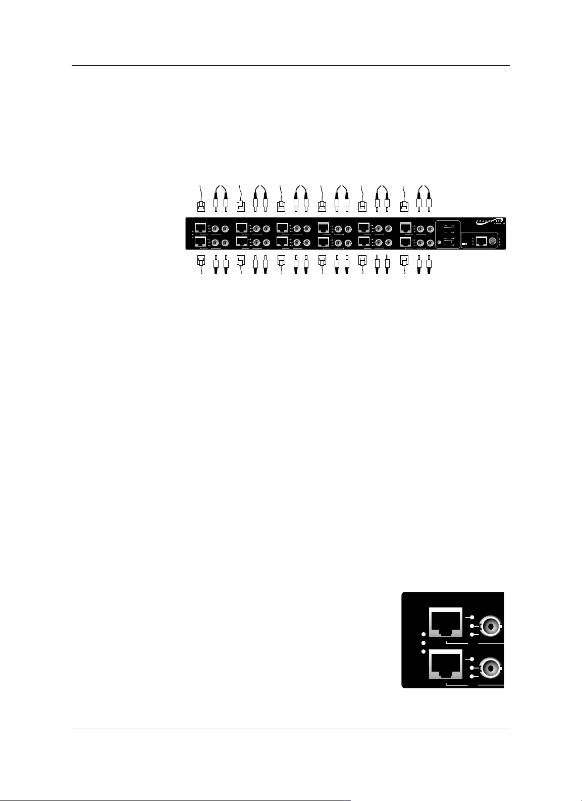
1.2 Media Converter Channels
Channels connect twisted-pair copper cable to fiber-optic cable.
Twisted-Pair Ports IEEE802.3-compliant 10BASE-T/100BASE-TX twisted-
pair ports operate at 10Mb/s or 100Mb/s, full-duplex or half-duplex.
Fiber-Optic Ports IEEE802.3-compliant 10BASE-FL/100BASE-FX fiber-
optic ports operate at 10Mb/s or 100Mb/s, full-duplex or half-duplex.
Channel LEDs A set of LEDs monitor the status
of EACH Media Converter channel.
T-LNK Steady LED indicates that twisted-
pair link has been established
between the channel and the
twisted-pair node
F-LNK Steady LED indicates that fiber link
has been established between the
channel and the fiber node
ACTIVE Steady LED indicates that fiber port is receiving traffic.
1.2
METTF10xx, MFETF10xx
T-LNK
F-LNK
1
ACTIVE
Tx
7
2
Tx
Rx
8
Tx
Rx
Tx
Tx
Rx
Rx
Rx
3
Tx
9
4
Rx
10
Tx
Tx
5
Tx
Rx
11
Tx
Rx
FDX
NORM
1 2 3 4
5 6
Managed Fast Ethernet 100BASE-TX to 100BASE-FX
1 2 3 4
5 6 7
TEST
HDX
6
Rx
Tx
Rx
RESET
12
MANAGEMENT
FDX
NORM
1 2 3 4
5 6
X
II
1 2 3 4
5 6 7
TEST
HDX
POWER
LNK
REC
Ready
BCKP
MAIN
TEST
Rx
Tx
Rx
T-LNK
F-LNK
ACTIVE
Tx
1
Tx
7

1.3 Channel Switches
Full-duplex/half-duplex mode selection
switches (DIP switches #1-6) allow the
network administrator to set EACH media
converter channel, separately, either to fullduplex or to half-duplex.
The Link Test switch (DIP switch #7)
enables or disables the Missing Link Test
feature for a block of six (6) Multichannel
Media Converter channels.
1.4 Reset Button
Located only on 100BASE-TX MFETF10xx series Multichannel Media
Converter models, the Rest button, if present, allows the network
administrator to reset ALL Multichannel Media Converter channel ports.
1.5 AC Power Supply Module/Optional Redundant
AC Power Supply Module
An AC Power Supply Module, installed at the back of the Multichannel
Media Converter before shipment, supplies power to the Multichannel
Media Converter through an external power cord connected to an external
AC outlet.
NOTE: The Multichannel Media Converter does not have an ON/OFF
power switch. Power is applied to, and removed from, the Multichannel
Media Converter by connecting and disconnecting the power cord.
The Multichannel Media Converter rear panel also contains an expansion
slot for an optional redundant Power Supply Module. When installed, the
optional redundant Power Supply Module shares the power load with the
main AC Power Supply Module. If one power supply fails, the remaining
power supply assumes the role of providing all power to the Multichannel
Media Converter, thereby protecting the Multichannel Media Converter
from a system failure.
NOTE: Both the redundant Power Supply Module and the main AC Power
Supply Module can be "hot swapped".
The MAIN power LED on the front panel of the
Multichannel Media ConverterLED is a steady amber
when thef the AC Power Supply Module is operating
properly. When the optional redundant Power Supply
Module is installed and operating properly, the BCKP
power LED is a steady green.
1 INTRODUCTION
1.3
MULTICHANNEL MEDIA CONVERTER
FDX
1 2 3 4
1 2 3 4
HDX
5 6
5 6 7
NORM
TEST
100BASE-TX to 100BASE-FX
ENT
POWER
BCKP
MAIN
TEST
1.6 Multichannel Media Converter Management
Module
TRANSITION Networks Multichannel Media Converters are shipped with
a Management Module installed and functional. Embedded SNMP
software in the Management Module allows network management of the
Multichannel Media Converter.
Connections to Management Module
The network administrator can manage the Multichannel Media Converter
using Management Module SNMP software accessed either through the
PS/2 serial port or through the RJ-45 network port.
Management Module LEDs
A set of LEDs monitor the status of the Management Module.
LNK Steady LEDindicates that a link has been
established to the Management Module
through the PS/2 serial port or through the
RJ-45 network port.
REC Steady LED indicates that the Management
Module is receiving traffic through the PS/2
serial port or through the RJ-45 network
port.
Ready Steady LED indicates that the Management
Module is properly installed and receiving power.
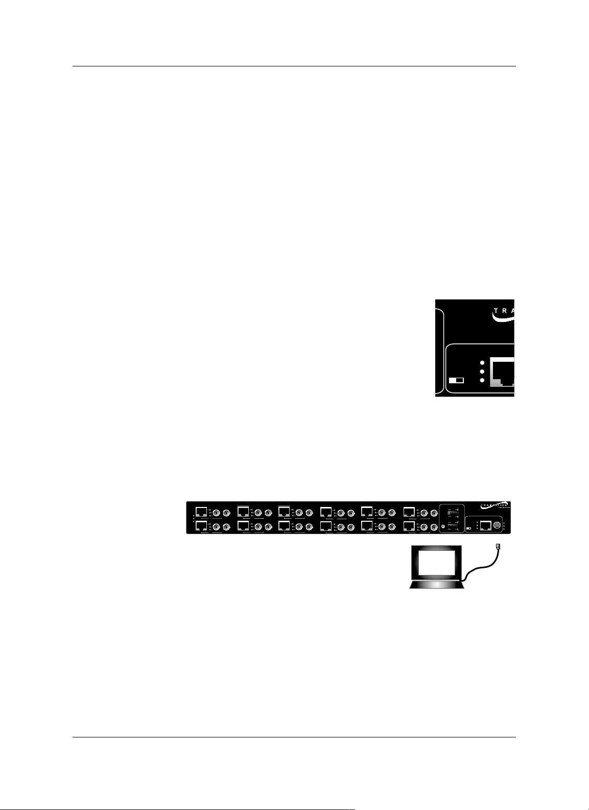
Serial Port
The network administrator can manage the Multichannel Media Converter
through a command-line interface at a terminal or terminal emulator
conected to the PS/2 port, through the supplied cable (PS/2 to DB9).
1.4
METTF10xx, MFETF10xx
Managed Fast Ethernet 1
MANAGEM
LNK
REC
X
II
Ready
T-LNK
F-LNK
1
ACTIVE
Tx
7
2
Tx
Rx
8
Tx
Rx
Tx
Attached terminal or terminal emulator
connected to PS/2 serial port via management cable.
Tx
Rx
Rx
Rx
3
Tx
Rx
9
Rx
Tx
4
Tx
Rx
10
Rx
Tx
5
Tx
11
Tx
Rx
FDX
NORM
1 2 3 4
5 6
Managed Fast Ethernet 100BASE-TX to 100BASE-FX
1 2 3 4
5 6 7
TEST
HDX
6
Rx
Tx
Rx
RESET
12
MANAGEMENT
FDX
LNK
NORM
1 2 3 4
5 6
REC
X
II
1 2 3 4
5 6 7
TEST
HDX
Ready
POWER
BCKP
MAIN
TEST
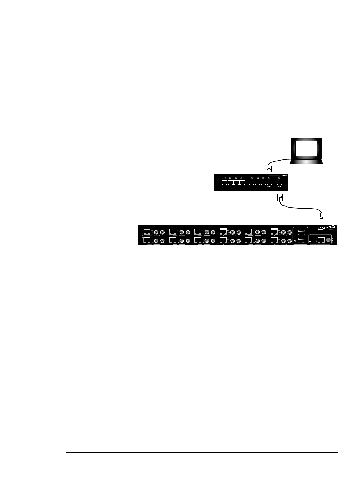
Network RJ-45 Connection
The RJ-45 Ethernet connection permits the network administrator to
manage the Multichannel Media Converter using the TRANSITION
Networks Multiport Management Software graphical interface (or other
SNMP application) at a remote network management station (NMS). The
RJ-45 Ethernet connection also permits the network administrator to use a
remote Telnet connection to the Multichannel Media Converters.
The Multichannel Media Converters must be attached, through the RJ-45
Ethernet port, to a network that is accessible (via IP) from the computer at
the remote location.
1.7 Multiport Management Software at Remote
NMS
TRANSITION Networks Multiport Management Software allows remote
management of the Multichannel Media Converter.
Clicking the Help button or the ? button at the Multiport Management
Software screen brings up links to an integrated set of HELP screens that
provides direction for using the Multiport Management Software and that
CAN BE VIEWED AND PRINTED FROM ANY STANDARD HTML
BROWSER.
1 INTRODUCTION
1.5
MULTICHANNEL MEDIA CONVERTER
Remote SNMP NMS
Network hub connected
to RJ-45 Ethernet port.
T-LNK
F-LNK
1
ACTIVE
Tx
7
2
Tx
Rx
8
Tx
Rx
Tx
Tx
Rx
Rx
Rx
3
Tx
Rx
9
Rx
Tx
4
Tx
Rx
10
Rx
Tx
5
Tx
11
Tx
Rx
FDX
NORM
1 2 3 4
5 6
Managed Fast Ethernet 100BASE-TX to 100BASE-FX
1 2 3 4
5 6 7
TEST
HDX
6
Rx
Tx
Rx
RESET
12
MANAGEMENT
FDX
LNK
NORM
1 2 3 4
5 6
REC
X
II
1 2 3 4
5 6 7
TEST
HDX
Ready
POWER
BCKP
MAIN
TEST


2 INSTALLATION
Direction for installing the TRANSITION Networks Multichannel Media
Converter is provided in the pages that follow.
2.1 Preparing the Site ..................................................................2.2
2.2 Unpacking METTF10xx, MFETF10xx Equipment ....................2.3
2.3 Installing Optional Redundant Power Supply Module ...........2.4
2.3.1 Setting Management Module Jumper ......................2.4
2.3.2 Installing Power Supply Module ..............................2.5
2.4 Installing Multichannel Media Converter at Site ....................2.6
2.4.1 Standard Rack Installation .......................................2.6
2.4.2 Table-Top Installation .............................................2.7
2.5 Powering the Multichannel Media Converter .......................2.8
2.6 Connecting Channel Ports to Network ..................................2.9
2.6.1 Setting FDX/HDX Channel Configuration Switches .2.9
2.6.2 Installing Fiber-optic Cable ...................................2.10
2.6.3 Installing Twisted-Pair Copper Cable ....................2.11
2.7 Setting Network Management Parameters ...........................2.12
2.8 Connecting to TCP/IP Network Management at Remote Network
Management Station (NMS) ................................................2.14
2.9 Installing Multipport Management Software at Remote NMS .....
.............................................................................................2.15
2.1
MULTICHANNEL MEDIA CONVERTER

2.1 Preparing the Site
Consider the following when choosing a site for the Multichannel Media
Converter:
• Select a site that provides conditions that conform to the
environmental requirements listed in the appendix.
• Select a site that is dust-free and moisture-free.
• Do not block the ventilation openings on the Multichannel Media
Converter. The site should allow for proper heat dissipation from,
and adequate ventilation around, the Multichannel Media
Converter.
• Be sure that the site will allow easy access to twisted-pair cables,
fiber-optic cables, and power cord(s).
• Use dedicated power circuits or power stabilizers to supply
reliable power to the Multichannel Media Converter.
• Keep twisted-pair cabling away from sources of electrical noise,
such as radios, electric motors, transmitters, broadband
amplifiers, power lines, and flourescent fixtures.
Also:
• ALL NODES connected to the ports on the media converter must
operate at the same speed: 10 Mb/s or 100 Mb/s, according to
Multichannel Media Converter model selected.
• The nodes connected to EACH CHANNEL on the Multichannel
Media Converter must operate in the same duplex mode, either
half-duplex or full-duplex. Do NOT, for instance, connect a node
operating at half-duplex to a twisted-pair port and then connect
another node operating at full-duplex to the fiber-optic port of the
same channel.
2.2
METTF10xx, MFETF10xx

2.2 Unpacking METTF10xx, MFETF10xx Equipment
Use the following list to verify the shipment:
Item
Multichannel Media Converter
Rack mounting kit
Four self-adhesive rubber feet
Power Cord
Management Control Cable
Muliipoint Management Software Disk
Redundant Power Supply Module
(with Power Cord)
User’s Guide
2 INSTALLATION
2.3
MULTICHANNEL MEDIA CONVERTER

2.3 Installing Optional Redundant Power Supply
Module
The standard Multichannel Media Converter is shipped with one MAIN
Power Supply Module installed at the back of the Multichannel Media
Converter cabinet and with a protective plate covering an installation slot
intended for a second, optional BACKUP Power Supply Module.
NOTE: Prior to installation of the optional redundant Power Supply
Module, a jumper setting on the Management Module already installed in
the Multichannel Media Converter must be changed from the NORMAL
position to the B(a)CK(u)P position.
WARNING: DO NOT CONNECT POWER SUPPLY MODULE TO
EXTERNAL POWER BEFORE INSTALLING IN MULTICHANNEL MEDIA
CONVERTER. FAILURE TO OBSERVE THIS WARNING COULD RESULT
IN EQUIPMENT DAMAGE AND/OR PERSONAL INJURY OR DEATH.
CAUTION: Wear a grounding device and observe electrostatic discharge
precautions when setting Management Module jumper and when
installing Power Supply Module in Multichannel Media Converter.
Failure to observe this caution could result in damage to, and subsequent
failure of, Management Module and/or Power Supply Module.
NOTE: Power Supply Modules can be “hot swapped”.
2.3.1 Setting Management Module Jumper
CAUTION: Failure to set the Management Module NJP1 jumper
correctly may result in false alarms (if the jumper is set to BCKP while
only one Power Supply Module is installed) or in failure to monitor the
redundant power supply (if a second Power Supply Module is installed
and the jumper is left in the NORMAL position).
To set the Management Module jumper:
1. Place the Multichannel Media Converter on a clean, stable
surface.
2. Locate the Management Module installed at the back left of the
Multichannel Media Converter.
3. Carefully remove the Management Module from the Multichannel
Media Converter by unscrewing two (2) thumbscrews that secure
the Management Module to the Multichannel Media Converter
and then gently sliding the Management Module from the
Multichannel Media Converter.
4. Place the Management Module on flat, stable surface and locate
the jumper identified as NJP1.
5. Using a small needle-nosed pliers or similar device, change the
2-position jumper labelled NJP1 from the NORMAL position to
the BACKUP position (indicated on Management Module circuit
board).
2.4
METTF10XX, MFETF10XX

6. Carefully slide the Management Module back into the
Multichannel Media Converter.
Ensure that the frame of the Management Module runs smoothly
between the guides at the bottom of the Multichannel Media
Converter. Note a slight resistance just before the Management
Module frame comes flush with the rear panel of the Multichannel
Media Converter. At this point, ensure that the edges of the
Management Module run parallel to the corresponding edges of
the Multichannel Media Converter. Then, apply gentle pressure to
seat the Management Module in the Multichannel Media
Converter.
7. Secure the Management Module to the Multichannel Media
Converter by tightening the two (2) thumbscrews.
2.3.2 Installing Power Supply Module
1. Locate the protective plate installed over the redundant Power
Supply Module installation slot at the rear of the Multichannel
Media Converter.
2. Remove the protective plate from the Multichannel Media
Converter by unscrewing two (2) thumbscrews that secure the
protective plate to the Multichannel Media Converter redundant
Power Supply Module installation slot.
3. Carefully slide the Power Supply Module into the Multichannel
Media Converter installation slot.
Ensure that the frame of the Power Supply Module runs smoothly
between the guides at the bottom of the Multichannel Media
Converter. Note a slight resistance just before the Power Supply
Module frame comes flush with the rear panel of the Multichannel
Media Converter. At this point, ensure that the edges of the
Management Module run parallel to the corresponding edges of
the Multichannel Media Converter. Then, apply gentle pressure to
seat the Power Supply Module in the Multichannel Media
Converter.
4. Secure the Power Supply Module to the Multichannel Media
Converter by tightening the two (2) thumbscrews.
2 INSTALLATION
2.5
MULTICHANNEL MEDIA CONVERTER

2.4 Installing Multichannel Media Converter at Site
The Multichannel Media Converter can be installed in a standard rack or
on a table, shelf, or other stable surface.
2.4.1 Standard Rack Installation
NOTE: Installation bracket mounting screws are provided. Rackmount
screws and clip nuts are NOT provided.
To install the Multichannel Media Converter in a standard rack:
1. Locate six (6) installation bracket screws (
provided) for each
Multichannel Media Converter chassis to be installed.
WARNING: Mount Multichannel Media Converter chassis
evenly and securely in rack. Failure to observe this warning
could allow the Multichannel Media Converter to fall, resulting
in equipment damage and/or possible injury to personnel.
2. Align universal mounting bracket in selected position against side
of Multichannel Media Converter chassis so that chassis
installation holes are visible through universal bracket installation
holes.
3. Using Phillips screwdriver, install three (3) screws through
mounting bracket into chassis installation holes on side of
Multichannel Media Converter.
4. Repeat steps 3 and 4 for second mounting bracket.
5. Locate four (4) screws (not
provided) and optional clip-nuts (not
provided) for each Multichannel Media Converter to be installed.
6. Carefully align Multichannel Media Converter at secure and level
position between the site rack mounting rails.
7. Install two (2) screws through right bracket into right mounting
rail and two (2) screws through left bracket into left mounting rail,
using clip nuts to secure if necessary.
2.6
LNK
Ready
net 100B
ASE-TX to 100B
1 2 3 4
5 6 7
1 2 3 4
5 6
TEST
HDX
NORM
1 2 3 4
5 6 7
1 2 3 4
5 6
HDX
FDX
METTF10XX, MFETF10XX
Tx
Tx
Rx
Tx
T-LNK
F-LNK
1
ACTIVE
Tx
Rx
7
Tx
Tx
Rx
Tx
T-LNK
F-LNK
4
1
ACTIVE
Tx
7
Rx
3
2
Tx
Tx
Rx
Rx
8
9
Rx
Rx
3
2
Tx
Tx
Rx
Rx
8
9
Rx
Rx
Tx
4
Rx
Tx
Rx
10
8
Rx
Tx
Rx
Tx
4
Tx
Rx
10
Tx
5
Tx
11
Tx
Rx
FDX
NORM
1 2 3 4
5 6
Managed Fast Ethernet 100B
ASE-TX to 100B
ASE-FX
1 2 3 4
5 6 7
TEST
HDX
6
12
Rx
Tx
Rx
1 2 3 4
1 2 3 4
1 2 3 4
1 2 3 4
RESET
FDX
Rx
1 2 3 4
5 6
1 2 3 4
5 6 7
HDX
RESET
FDX
NORM
5 6
Managed Fast Ethernet 100BASE-TX to 100BASE-FX
5 6 7
TEST
HDX
FDX
NORM
5 6
5 6 7
TEST
HDX
MANAGEMENT
POWER
LNK
NORM
BCKP
REC
MAIN
X
II
TEST
TEST
Ready
MANAGEMENT
POWER
LNK
BCKP
REC
MAIN
X
II
TEST
Ready
5
Tx
Rx
11
Rx
Tx
6
Rx
Tx
12

2.4.2 Table-Top Installation
The Multichannel Media Converter is shipped with four (4) rubber feet for
optional installation on table or other flat, stable surface.
CAUTION: Do not place the Multichannel Media Converter on active,
heat generating equipment and avoid placing other devices on top of the
Multichannel Media Converter. Failure to observe this caution could
cause Multichannel Media Converter to fail.
1. Select a level, secure surface in a well-ventilated area.
2. Remove the adhesive protective sheet from the rubber feet
(
provided
) and affix the feet to the corners on the bottom of the
Multichannel Media Converter, approximately 1 centimeter from
each edge.
3. Set the Multichannel Media Converter securely upright on the
stable surface.
2 INSTALLATION
2.7
MULTICHANNEL MEDIA CONVERTER

2.5 Powering the Multichannel Media Converter
NOTE: The Multichannel Media Converter does NOT have a power
ON/OFF switch. Power is applied to, and removed from, the Multichannel
Media Converter by connecting and disconnecting the power cord.
NOTE: The Main Power Supply Module and the Redundant (backup)
Power Supply Module each has a separate power cord. Increase
protection to the Multichannel Media Converter from operational failure
due to power circuit failure by connecting the two power cords to outlets
on separate power circuits.
To power the Multichannel Media Converter through the AC Power
Supply Module(s):
1. Locate Power Supply Module(s) at back of Multichannel Media
Converter.
2. Connect female end of power cord to power receptacle on Power
Supply Module.
3. Plug male end of power cord into correct voltage AC rack or wall
outlet.
4. If optional Redundant (backup) Power Supply Module is installed
in Multichannel Media Converter, repeat steps 2 and 3 for second
Power Supply Module.
4. Verify that Multichannel Media Converter is powered by
observing illuminated LED(s) and noting operation of Power
Supply Module fan(s).
2.8
METTF10xx, MFETF10xx

2.6 Connecting Channel Ports to Network
Each channel port is connected, using twisted-pair copper and fiber-optic
cable, to network devices.
2.6.1 Setting FDX/HDX Channel Configuration Switches
FDX/HDX (F(ull-)D(uple)X and H(alf)D(uple)X) refers to the manner in
which a network device sends and receives data on the network. A
network device that is operating in half-duplex mode either sends data or
receives data, in turn. A network device that is operating in full-duplex
mode both sends and receives data, simultaneously.
NOTE: The Multichannel Media Converter is an HDX/FDX autonegotiating device which transmits "FDX Advertising" signals to attached
network devices and forces FDX-capable network devices to FDX. Though
each channel of the Multichannel Media Converter can operate in either
full-duplex or half-duplex mode, setting the entire network to full-duplex
mode maximizes throughput and distances. To achieve this, ALL
interconnected devices must be capable of full-duplex and properly set.
CAUTION: If any network devices connected to a channel are not
capable of full-duplex (FDX), then all other channel devices must be set
to half-duplex (HDX), INCLUDING THE MULTICHANNEL MEDIA
CONVERTER CHANNEL. Failure to observe this caution will result in
excess network collisions.
NOTE: Each channel FDX/HDX switch must be set separately. Do NOT
connect a node operating at half-duplex to a twisted-pair port and then
connect another node operating at full-duplex to the fiber-optic port of the
same channel. Do NOT connect a node operating at full-duplex to a
twisted-pair port and then connect another node operating at half-duplex
to the fiber-optic port of the same channel.
Setting Full-Duplex/Half-Duplex Configuration Switches
1. Locate six (6) FDX/HDX switches that are
associated with six (6) copper-to-fiber media
converter channels (DIP switches #1-6 at
front of Multichannel Media Converter).
2. Referring to full-duplex/half-duplex mode of
network devices to be attached to channel
nodes, FOR EACH CHANNEL, set the
associated configuration switch to FDX (fullduplex): UP or to HDX (half-duplex): DOWN.
2 INSTALLATION
2.9
MULTICHANNEL MEDIA CONVERTER
FDX
1 2 3 4
1 2 3 4
HDX
5 6
5 6 7
NO
TE

2.6.2 Installing Fiber-optic Cable
Refer to the appendix for cable specifications for the 10BASE-FL or the
100BASE-FX fiber-optic installation.
Installing Cable
1. Locate or build 10BASE-FL-compliant or 100BASE-FX-compliant
cables (depending upon Multichannel Media Converter selected
for the site), with male two-stranded TX to RX connectors installed
at both ends.
2. Connect TX and RX connectors at one end of cable to mating
Multichannel Media Converter TX and RX fiber-optic connector.
3. Connect cable with connector installed at TX location on
Multichannel Media Converter channel to RX location on
attached network device.
4. Connect cable with connector installed at RX location on
Multichannel Media Converter channel to TX location on
attached network device.
Testing Fiber Link(s)
NOTE: The Link Test switch (DIP switch #7) enables and disables the Link
Test feature for a block of six (6) Multichannel Media Converter channels.
When the Link Test feature is enabled (set to NORMAL position), if the
Multichannel Media Converter senses loss of a twisted-pair link, the
associated fiber-optic link is cut. Then the remote device senses loss of the
fiber-optic link and, if the remote device is another Multichannel Media
Converter also set to NORMAL mode, the remote Multichannel Media
Converter disables the twisted-pair port. Finally the remote device
becomes aware that the link to the opposite end device connected to this
channel is not fully functional and subsequently triggers a back-up
mechanism (if so equipped) and/or alerts the network manager.
Thus, when the Link Test feature is enabled (set to NORMAL position), if a
Multichannel Media Converter does not detect a good link on the twistedpair 10BASE-T /100BASE-TX side of any channel, the Multichannel Media
Converter disables all data transmission (including active-idle) on the
fiber-optic 10BASE-FL/100BASE-FX side of that channel.
However, the network administrator facing a device with no link
indication cannot tell whether that no link indication is due to the loss of
the fiber-optic link or due to loss of the remote twisted-pair link.
Therefore, when installing a fiber-optic network, disable the Link Test
feature (set to TEST position) to establish that the Multichannel Media
Converter fiber-optic links are operational and THEN connect network
devices through the twisted-pair links.
2.10
METTF10xx, MFETF10xx
TX
RX
TX
RX

To perform a link test:
1. Verify that all network devices connected to the fiber-optic ports
on the Multichannel Media Converter are powered ON and
operational.
2. Cycle power to the Multichannel Media Converter by ptessing the
RESET botton, if preseny, or bydisconnecting the power cord from
the external AC outlet and then reconnecting the power cord to
the external AC outlet.
Verify that the Multichannel
Media Converter is powered ON
and is operational:
• Verify that the Multichannel
Media Converter MAIN LED
is a steady amber, indicating
that the unit is receiving power.
• If an optional redundant power supply is installed, verify that
the BCKP LED is a steady green.
• Verify that the power supply fan(s) is/are operational.
3. For each set of six (6) channels, set the Link Test switch (DIP
switch #7) to the TEST position.
The TEST LED(s) at the front right panel should be amber.
4. Verify that the F-LNK LED for EACH Multichannel Media
Converter fiber-optic port with installed fiber-optic cable is
illuminated, indicating that a link exists between the fiber optic
port on the Multichannel Media Converter and the network
device connected to the channel port.
5. Return the Link Test switch (DIP switch #7) to the NORMAL
position.
2.6.3 Installing Twisted-Pair Copper Cable
Refer to the appendix for cable specifications for the 10BASE-T or the
100BASE-TX twisted-pair copper installation.
Installing Cable
1. Locate or build 10BASE-T or 100BASE-TX-compliant cables
(depending upon Multichannel Media Converter selected for the
site) with male RJ-45 connectors installed at both ends.
NOTE: Use a straight-through cable to connect a hub or a switch
to a twisted-pair channel port on the Multichannel Media
Converter. Use a crossover cable to connect a workstation to a
twisted-pair channel port on the Multichannel Media Converter.
2. Connect RJ-45 connector at one end of cable to Multichannel
Media Converter RJ-45 twisted-pair channel port connector.
3. Connect RJ-45 connector at other end of cable to device RJ-45
port connector.
2 INSTALLATION
2.11
MULTICHANNEL MEDIA CONVERTER
FDX
1 2 3 4
1 2 3 4
HDX
5 6
5 6 7
NORM
TEST

2.7 Setting Network Management Parameters
CAUTION: IP parameters should be set and/or modified
ONLYat the
attached terminal Interface.
To set the Multichannel Media Converter network parameters:
1. Locate a PC equipped with any terminal emulation program.
2. Connect the Multichannel Media Converter to the PC by
connecting the miniDIN end of the control cable (provided) to the
Multichannel Media Converter Management PS/2 port and the
other end of the cable to the PC DB-9 serial port connector.
NOTE: By default, the Multichannel Media Converter uses the
following serial port parameter values:
bits per second 9600
stop bits 1
data bits 8
parity NONE
flow control Xon/Xoff
3. Using methods appropriate to the attached terminal, verify that
the serial port parameters of the attached terminal match the
Multichannel Media Converter port parameter values. If
necessary, modify the attached terminal port parameter values.
4. Start the terminal emulation program.
5. Cycle power to the Multichannel Media Converter by
disconnecting the power cord from the external AC outlet and
then reconnecting the power cord to the external AC outlet..
After a few seconds the start up screen comes up.
Management card configuration
-----------------------------------------------------
NETWORK PARAMETERS:
-------------------
IP address on LAN is 192.168.1.99
CONSOLE PARAMETERS:
-------------------
console channel will use a baud rate of 9600
BOARD PARAMETERS:
-----------------
Processor : MPC850, Running at 50Mhz
Board Info : Management Board
Board memory : FLASH : 4Mbytes
SDRAM : 4Mbytes
Board's Ethernet hardware address :
0:A0:D2:2F:80:82
-----------------------------------------------------
To change any of this, press any key within 5 seconds
6. Immediately press any key in order to access the configuration
procedure. Type ‘m’ (or ‘M’) to modify the current settings.
The software then prompts with a series of default parameter values in
braces and a prompt either to press the ‘Return’ key to keep a displayed
parameter or to enter a new value.
2.12
METTF10XX, MFETF10XX

(M)odify any of this or (C)ontinue? [M] m
For each of the following questions, you can press
<Return> to select the value shown in braces, or you
can enter a new value.
NETWORK PARAMETERS:
------------------Do you want a LAN interface? [Y]
This board's LAN IP address(0.0.0.0 = RARP)?
[192.168.1.99]
Use a subnet mask for the LAN interface? [N] y
Subnet mask for LAN (0 for none)? [0.0.0.0]
Should there be a default gateway for packet routing?
[N] y
What is its IP address? [0.0.0.0]
CONSOLE PARAMETERS:
------------------Baud rate for serial channels [9600]
ETHERNET PARAMETERS:
-------------------Do you want to change the board's Ethernet address?
[N] y
Byte 0 must be 00
What should byte 1 be? [A0]
What should byte 2 be? [D2]
What should byte 3 be? [2F]
What should byte 4 be? [80]
What should byte 5 be? [82]
SNMP PARAMETERS:
---------------Get community [public]
Set community [private]
Trap destination [192.168.1.15]
Trap community [trap]
System name [LAN]
System location [location]
System Contact [administrator]
How long (in seconds) should CPU delay before
starting up? [5]
NOTE: Changing the CPU delay value above from 5 to 15 makes it easier
to continue again later.
When configuration is complete, the startup screen comes up with the
new parameters.
To continue modifying the configuration parameters, again type ‘m’ to
modify.
7. Type ‘c’ to save the configuration, initialize the system, and
continue:
Updating parameter storage. This may take a
while...Done
Initialization...
8. Observe the illuminated Ready Multichannel Media Converter
Management LED.
NOTE: The Multichannel Media Converter can be managed at the
terminal emulation interface. See Section 3 OPERATION.
2 INSTALLATION
2.13
MULTICHANNEL MEDIA CONVERTER

2.8 Connecting to TCP/IP Network Management at
Remote Network Management Station (NMS)
It is recommended that the Multichannel Media Converter RJ-45
MANAGEMENT port be connected to the TCP/IP network management
station (NMS) through a switch or a hub that also is connected to other
managed network devices. If the Multichannel Media Converter RJ-45
MANAGEMENT port is connected directly to the NMS, the NMS will
manage only that Multichannel Media Converter.
1. Locate or build a 10BASE-T-compliant twisted-pair shielded cable
with RJ-45 plug connectors installed at both ends.
NOTE: Straight-through or crossover cable can be used, since the
Multichannel Media Converter provides either an RJ-45 10BASE-T
Ethernet port with an associated MDI-II/MDI-X switch or two
RJ-45 10BASE-T ports, one configured as straight-through and the
other configured as crossover, for connecting the Multichannel
Media Converter to TCP/IP network management.
2. Connect RJ-45 connector at one end of cable to Multichannel
Media Converter RJ-45 twisted-pair Management port.
3. Connect RJ-45 connector at other end of cable to RJ-45 port on
10BASE-T-compliant hub or switch.
4. Verify that the Multichannel Media Converter MANAGEMENT
L(i)NK LED is illuminated. If not, change the MDI-II/MDI-X switch
setting or the position of the RJ-45 shielded cable connection.
5. Verify that the appropriate LINK indicator on the hub or switch is
illuminated.
NOTE: If installing Multiport Management Software at the NMS,
skip the following steps and proceed to the next section.
6. Referring to documentation that comes with the NMS
management application, copy the MIB file (SUPPLIED - located
on the Multiport Management Software to the default NMS
management application directory.
7. Again referring to documentation that comes with the NMS
management application, add the new MIB to the NMS
management application list and recompile the MIBs.
2.14
METTF10xx, MFETF10xx

2.9 Installing Multiport Management Software at
Remote NMS
NOTE: Multiport Management Software 1.0 runs on a variety of platforms.
On most Win32* platforms, Multiport Management Software 1.0 can be
used as "standalone" or as an integrated component with HP Open View.
Using HP Open View on HP UX Unix and Solaris, Multiport Management
Software runs only as an integrated component ; there is no "standalone"
Unix version of this software.
To install the TRANSITION Networks Multiport Management Software
graphical interface at a remote network management station (NMS):
1. Ensure that the Multichannel Media Converter is attached,
through the 10BASE-T port, to a TCP/IP network that is accessible
(via IP) from the network management station.
2. At the network management station, load the Multiport
Management Software from the Multipoint Management Software
Disk:
Win32 Systems
Run Setup.exe (located in the \TransitionNetworks\win
directory).
Unix Systems
Run install.sh (located in the /TransitionNetworks/unix
directory).
*Microsoft Windows 95, 98, ME, NT 4.0, Windows 2000
2 INSTALLATION
2.15
MULTICHANNEL MEDIA CONVERTER
Remote SNMP NMS
TCP/IP
T-LNK
F-LNK
1
ACTIVE
Tx
7
2
Tx
Rx
8
Tx
Rx
Tx
Tx
Rx
Rx
Rx
3
Tx
Rx
9
Rx
Tx
4
Tx
Rx
10
Rx
Tx
5
Tx
11
Tx
Rx
FDX
1 2 3 4
1 2 3 4
6
Rx
12
HDX
FDX
Tx
Rx
1 2 3 4
1 2 3 4
HDX
RESET
NORM
5 6
Managed Fast Ethernet 100BASE-TX to 100BASE-FX
5 6 7
TEST
MANAGEMENT
LNK
NORM
5 6
REC
X
II
5 6 7
TEST
Ready
POWER
BCKP
MAIN
TEST


3.1
MULTICHANNEL MEDIA CONVERTER
3. OPERATION
Daily operation of the TRANSITION Networks METTF10xx, MFETF10xx
Multichannel Media Converter requires no network administrator activity
except the occasional monitoring of status LED indicators at the front of
the Multichannel Media Converter.
Optionally, the network administrator can monitor and manage the
Multichannel Media Converter using an attached terminal or terminal
emulator or at a remote Telnet connection. The network administrator
also can monitor and manage the Multichannel Media Converter using an
SNMP application such as TRANSITION Networks Multiport Management
Software at a remote Network Management Station (NMS).
Direction is provided in the pages that follow:
3.1 Using Status LEDs .................................................................3.2
3.2 Using a Terminal Emulator ....................................................3.3
3.3 Using Multiport Management Software at Remote NMS ......3.6

3.2
METTF10XX, MFETF10XX
3.1 Using Status LEDs
Status LEDs monitor Multichannel Media Converter operation.
Power Supply and Link Test Switch LEDs
LED Color Indicates
MAIN Amber The main power supply
is functional.
Weak/flashing The main power supply
Amber is failing or failed.
BCKP Green The optional redundant
power supply, if installed,
is functioning normally.
Weak/flashing The optional redundant power supply, if
Green installed, is failing or failed.
NORM Steady Green The unit is NOT performing a Link Test.
TEST Steady Amber The unit is performing a Link Test on the
fiber-optic ports.
Management LEDs
LED Color Indicates
LNK Steady Green A link is established
between the Management
Module and the connected
network device.
REC Flashing Green The Management Module
is receiving data.
Ready Steady The Management Module is installed and
functioning normally.
Channel LEDs
LED Color Indicates
T-LNK Steady Green A link is
established
between the
twisted-pair
port and the
connected
network device.
F-LNK Steady Green A link is established between the fiber-
optic port and the connected network
device.
ACTIVE Flashing Amber The fiber-optic port is receiving data.
0BASE-TX to 100BASE-FX
NT
POWER
BCKP
MAIN
TEST
anaged Fast Ethernet 1
MANAGEM
LNK
REC
II
Ready
T-LNK
F-LNK
ACTIVE
Tx
1
Tx
7

3 OPERATION
3.3
MULTICHANNEL MEDIA CONVERTER
3.2 Using a Terminal Emulator
The Multichannel Media Converter Management Module terminal
emulator interface permits the network administrator to display status
messages and to display and to modify selected network settings.
CAUTION: IP parameters can be set and/or modified ONLYat the
attached terminal Interface.
The Multichannel Media Converter command-line interface is accessible
using a terminal or terminal emulator attached to the PS/2 serial port on
the Multichannel Media Converter.
NOTE: The serial port cable is attached directly to a DTE device through
the serial port management control cable shipped with the Multichannel
Media Converter.
1. Locate a PC equipped with any terminal emulation program.
2. Connect the Multichannel Media Converter to the PC by
connecting the miniDIN end of the control cable (
provided) to the
Multichannel Media Converter Management PS/2 port and the
other end of the cable to the PC DB-9 serial port connector.
NOTE: By default, the Multichannel Media Converter uses the
following serial port parameter values:
bits per second 9600
stop bits 1
data bits 8
parity NONE
flow control Xon/Xoff
3. Using methods appropriate to the attached terminal, verify that
the serial port parameters of the attached terminal match the
Multichannel Media Converter port parameter values. If
necessary, modify the attached terminal port parameter values.
4. Start the terminal emulation program.
5. Cycle power to the Multichannel Media Converter by
disconnecting the power cord from the external AC outlet and
then reconnecting the power cord to the external AC outlet...
After system initialization, a banner display comes up.
****************************************************
* Software version: v2.0.4T *
* Version date: 25/02/01 *
* Vendor: Transitiob Betworks *
* Model: MFETF1013-120 *
****************************************************

3.4
METTF10xx, MFETF10xx
Thrn the main menu comes up with the following options:
1. Device status
2. Device control
3. File download (TFTP)
Select (1-3):
NOTE: The TFTP feature is NOT enabled in the current software version.
At the main menu, select 1 to display the device (port(s)) status menu,
which shows the status of each Multichannel Media Converter channel
(including twisted-pair and fiber-optic link status, test state, and duplex
mode), as well as the status of the power supplies and the chassis
temperature.
Port(s) status:
===============
Channel TP Link FO Link Test FDX
=====================================================
01 OFF OFF OFF ON
02 OFF OFF OFF ON
03 OFF OFF OFF ON
04 OFF OFF OFF ON
05 OFF OFF OFF ON
06 OFF OFF OFF ON
07 OFF OFF OFF ON
08 OFF OFF OFF ON
09 OFF OFF OFF ON
10 OFF OFF OFF
11 OFF OFF OFF ON
12 OFF OFF OFF ON
Main Power supply : OK
Backup Power supply : NOT INSTALLED
Temperature: 35
Press <CR> to continue...
Return to the main menu by pressing <return>.
Using Terminal Emulator

3 OPERATION
3.5
MULTICHANNEL MEDIA CONVERTER
At the main menu, select option 2 to display the device control menu,
which allows the network administrator to reset the Multichannel Media
Converter cards, to change test mode, and to enter the duplex mode
change menu.
Device control:
===============
1. Reset bottom card.
2. Change bottom test.
3. Reset top card.
4. Change top test.
5. Change HDX commands.
0. Main menu.
Select (0-5):
NOTE: Options 3 and 4 do not appear in Multichannel Media Converters
with only six channels.
Return to the main menu by selecting 0.
At the device control menu, select option 5 to display the HDX control
menu. At the HDX control menu, toggle selected channels between halfduplex mode and full-duplex mode. Selecting one of the numbered
options at the HDX control menu changes the duplex mode of the
associated channel: Selecting 5 toggles the duplex mode of channel 5.
HDX control:
============
1. Change CH1 - FDX/HDX.
2. Change CH2 - FDX/HDX.
3. Change CH3 - FDX/HDX.
4. Change CH4 - FDX/HDX.
5. Change CH5 - FDX/HDX.
6. Change CH6 - FDX/HDX.
7. Change CH7 - FDX/HDX.
8. Change CH8 - FDX/HDX.
9. Change CH9 - FDX/HDX.
10. Change CH10 - FDX/HDX.
11. Change CH11 - FDX/HDX.
12. Change CH12 - FDX/HDX.
0. Device control menu.
Select (0-12):
NOTE: Options 7-12 do not appear in Multichannel Media Converters
with only six channels.
View the change in the device status listing (accessible from the main
menu). Return to the device control menu by selecting 0.

3.6
METTF10xx, MFETF10xx
3.3 Using Multiport Management Software at
Remote NMS
The LED indicators available on the physical METTF10xx or MFETF10xx
Multichannel Media Converter also can be displayed graphically at a
remote network management station (NMS), using installed TRANSITION
Networks Multiport Management Software.
The Multiport Management Software brings up a drawing that represents
each selected managed METTF10xx or MFETF10xx Multichannel Media
Converter, identified by IP address. “LED indicators” represent physical
LEDs on physical METTF10xx or MFETF10xx devices. The “LEDs” are
"illuminated" to indicate the state of the METTF10xx or MFETF10xx at the
time of the last Multiport Management Software polling.
In addition, METTF10xx or MFETF10xx Multichannel Media Converter
status information is available in text format.
To bring up the Multiport Management Software graphical display for a
selected METTF10xx or MFETF10xx Multichannel Media Converter:
Standalone Win32* Systems
1. At the remote NMS, access the MULTIPORT MANAGEMENT
SOFTWARE ICON from the START menu within the TRANSITION
options in the PROGRAMS menu.
The Multiport Management Software comes up and then prompts
for the IP address of the METTF10xx or MFETF10xx Multichannel
Meda Converter to be managed.
2. Enter the IP address of the manageable METTF10xx or MFETF10xx
Multichannel Media Converter.
A graphical representation of the selected METTF10xx or
MFETF10xx Multichannel Meda Converter comes up, with the
node IP address displayed in the upper left corner of the screen.
System HP Open View
1. At the remote NMS, from the GRAPHICAL USER INTERFACE,
select the TRANSITION icon.
2. Select the TOOLS icon from the menu bar and scroll down to
select the MULTIPORTMANAGER option.
3. Scroll down to select the node (IP address) of the manageable
METTF10xx or MFETF10xx Multichannel Media Converter.
A graphical representation of the selected METTF10xx or
MFETF10xx Multichannel Meda Converter comes up, with the
node IP address displayed in the upper left corner of the screen.
*Microsoft Windows 95, 98, ME, NT 4.0, Windows 2000
CAUTION: Do NOT make IP configuration changes from the Multiport
Management Software text-format displays. Make IP configuration
changes ONLY through the serial port command-line interface. (See
Section 2. Installation.) Failure to observe this caution could result in
unanticipated configuration faults and failures.

3 OPERATION
3.7
MULTICHANNEL MEDIA CONVERTER
NOTE: Click the Help button OR the ? button on any screen to bring up
links to an integrated set of HELP screens that CAN BE VIEWED AND
PRINTED FROM ANY STANDARD HTML BROWSER:
The followng conventions are used at the Multiport Management Software
graphical interface:
TP* Link, Fiber Link, TP* Activity, and Fiber Activity are either green
for up/detected or dim gray for down/not detected.
Full Duplex Mode (Fast Ethernet devices only) is green when running
in Full-Duplex Mode and dim gray when running in Half-Duplex
Mode. To change Duplex Mode (only on Fast Ethernet devices), click
on the button labeled: Toggle Duplex Mode and wait. (Several polling
cycles may be required for the application to "recognize" the change.)
Main Power Supply Status is green for OK or red for fail.
Backup Power Supply Status is green for OK, red for fail, or dim gray
for not installed.
Temperature provides the inside temperature of the device in degrees
Celsius.
Poll Rate is the time interval, in seconds, that the application polls the
managed device. To change the Poll Rate, enter a new integer value
and press the "Enter" key.
System up Time is the time in days, hours, minutes, and seconds
since the last power-cycle (reboot) of the managed device.
Refresh issues a "get request" on all data associated with the open
screen. (Same as a poll.).
MIB2sysName field is a read/write field for the system name. To
change the system name entry, type a new entry in the MIB2sysName
field and press the "enter" key. Changes appear at the next polling
interval.
MIB2sysLocation is a read/write field for the system location. To
change the system location entry, type a new entry in the
MIB2sysLocation field and press the "enter" key. Changes appear at
the next polling interval.
MIB2sysContact is a read/write field for the system administrator
contact. To change the system administrator contact entry, type a new
entry in the MIB2sysContact field and press the "enter" key. Changes
appear at the next polling interval.
MIB2sysDescription is a read-only field for the system description.
*twisted-pair


4 MAINTENANCE
4.1
MULTICHANNEL MEDIA CONVERTER
4 MAINTENANCE
Maintenance direction for the TRANSITION Networks Multichannel
Media Converter provided in this section includes:
4.1 Fault Isolation and Recovery .................................................4.2
4.2 Hardware Replacement Procedures ......................................4.5
4.2.1 Replacing Management Module ..............................4.5
4.2.2 Replacing AC Power Supply Module ......................4.6

4.1 Fault Isolation and Recovery
Determine the answers to the following questions and, where appropriate,
take the indicated action(s):
1. Does Multichannel Media Converter Reset Correct the
Condition?
• Press the RESET button at the front of the Multichannel
Media Converter Management Module for about one (1)
second.
The LEDs at the front of the Multichannel Media Converter
should flash once, then the Multichannel Media Converter
should return to normal network operation.
• Observe the results.
2. Is Multichannel Media Converter Receiving Power?
• Inspect power LED indicators at the front of the
Multichannel Media Converter.
If the MAIN LED is OFF:
• Ensure that the power cord for the MAIN power supply is
connected securely to the Multichannel Media Converter
MAIN power supply and to the power outlet.
• Ensure that the MAIN power supply module is seated firmly
in the Multichannel Media Converter.
• Ensure that the MAIN power supply module power outlet
has power and that the AC input power source is between
100VAC and 240VAC.
• Contact TRANSITION Networks Technical Support.
If an optional redundant power supply is installed but the BCKP
LED is OFF:
• Ensure that the power cord for the redundant power supply
is connected securely to the Multichannel Media Converter
redundant power supply and to the power outlet.
• Ensure that the redundant power supply module is seated
firmly in the Multichannel Media Converter.
• Ensure that the redundant power supply module power
outlet has power and that the AC input power source is
between 100VAC and 240VAC.
• Contact TRANSITION Networks Technical Support.
4.2
METTF10XX, MFETF10XX

4 MAINTENANCE
4.3
MULTICHANNEL MEDIA CONVERTER
3. Are Channel Links Good?
If the T-LNK LED for a twisted pair port is OFF:
• Ensure the network device connected to the twisted-pair
channel port is powered ON.
• Ensure that the twisted-pair cable is connected securely both
to the channel port and to the network device.
• If the network device connected to the port is a workstation,
ensure that the cable is in the crossover configuration.
• If the network device connected to the port is a hub or
switch, ensure that the cable is in the straight-through
configuration.
• Ensure that the network device connected to the port is
operating at correct speed: 10 Mb/s or 100 Mb/s.
If the F-LNK LED for a fiber optic port is OFF:
• Ensure that the network device connected properly to the
fiber-optic port is powered ON.
• Ensure that the fiber-optic cable is connected to the fiberoptic port and to the network device.
• Ensure that the network device connected to the fiber-optic
port is operating at correct speed: 10 Mb/s or 100 Mb/s.
• Set the Link Test switch(es) to TEST position (to isolate fiber
link faults from faults on the twisted-pair network).
Allow 5-10 seconds for all devices to link-up. All LNK LEDs
should illuminated
NOTEL Remember to reset Link Test switch(es) to NORMAL
after procedure is completed
• Verify that the maximum allowable loss budget on the fiberoptic cable is within acceptable limits.
If a LINK LED of a port is illuminated but there is a
communication problem with the port:
• Ensure that the duplex setting is set the same on the nodes
connected to the twisted-pair and to the fiber-optic ports of
the media converter channel.
If all LNK LEDs are OFF but all network decices and fiber-optic
cable are connected, a link-up problem is suspected:
• Contact TRANSITION Networks Technical Support.

4. Is Management Connection Good?
If the Management READY LED is OFF:
• Ensure that the Management Module is seated firmly in the
Multichannel Media Converter.
• Ensure that the Management Module is configured properly
(See Section 3 INSTALLATION).
If the configuration menu isn’t readable or doesn’t appear at all:
• Ensure that the serial cable is good.
• Ensure that the terminal settings are good.
If there is no SNMP response from the manager:
• Check the IP address on the configuration menu.
• Try to use the "ping" command.
If there is no “ping”
• Check the Ethernet cable.
• Check the LNK LED.
If there are no traps:
• Check the SNMP manager IP address in the trap destination
on the configuration menu.
If the Multichannel Media Converter doesn’t appear in the MIB
browser:
• Ensure that the Multichannel Media Converter MIB file is
copied to the proper location in the remote Network
Management Station.
• Ensure that the MIBs are compiled with the new file.
4. Is the Management Module connected to an active
10BASE-T Ethernet port?
• Ensure that the Management LNK LED indicator is
illuminated, indicating a good link.
• Ensure that the Management REC LED indicator is blinking,
indicating that the Management Module is receiving data.
Failure may indicate that Multichannel Media Converter
Management Module connection to the network has failed.
• Verify the integrity of the 10BASE-T hub/switch port to
which the Multichannel Media Converter is attached.
• Verify the integrity of the 10BASE-T twisted-pair Ethernet
cable that leads from the hub/switch to the Multichannel
Media Converter.
• Contact TRANSITION Networks Technical Support.
4.4
METTF10XX, MFETF10XX
Fault Isolation and Recovery

4.2 Hardware Replacement Procedures
WARNING: The METTF10xx, MFETF10xx series Multichannel Media
Converter contains no user-serviceable parts. DO NOT, UNDER ANY
CIRCUMSTANCES, open and attempt to repair Multichannel Media
Converter equipment. Failure to observe this warning could result in
personal injury and/or death from electrical shock.
NOTE: Failure to observe the above warning will immediately void any
warranty.
4.2.1 Replacing Management Module
CAUTION: Wear a grounding device and observe electrostatic discharge
precautions when replacing Management Module in the Multichannel
Media Converter. Failure to observe this caution could result in damage
to, and subsequent failure of, the Management Module.
To replace the Management Module:
1. If the Multichannel Media Converter is powered, disconnect ALL
power cables from AC wall outlet.
2. Locate Management Module to be replaced at the rear of the
Multichannel Media Converter.
3. Carefully remove the Management Module to be replaced from
the Multichannel Media Converter by unscrewing two (2)
thumbscrews that secure the Management Module to the
Multichannel Media Converter and gently sliding the
Management Module from the Multichannel Media Converter.
4. Carefully slide the replacement Management Module into the
Multichannel Media Converter.
Ensure that the frame of the Management Module runs smoothly
between the guides at the bottom of the Multichannel Media
Converter. Note a slight resistance just before the Management
Module frame comes flush with the rear panel of the
Multichannel Media Converter. At this point, ensure that the
edges of the Management Module run parallel to the
corresponding edges of the Multichannel Media Converter. Then,
apply gentle pressure to seat the Management Module in the
Multichannel Media Converter.
5. Tighten the two (2) thumbscrews that secure the replacement
Management Module to the Multichannel Media Converter.
4 MAINTENANCE
4.5
MULTICHANNEL MEDIA CONVERTER

4.6
METTF10xx, MFETF10xx
Hardware Replacement Procedures
4.2.2 Replacing AC Power Supply Module
WARNING: DO NOT CONNECT POWER SUPPLY MODULE TO AC
POWER BEFORE INSTALLING IN MULTICHANNEL MEDIA
CONVERTER. FAILURE TO OBSERVE THIS CAUTION COULD RESULT
IN EQUIPMENT DAMAGE AND/OR PERSONAL INJURY OR DEATH.
CAUTION: Wear a grounding device and observe electrostatic discharge
precautions when replacing Power Supply Module in the Multichannel
Media Converter. Failure to observe this caution could result in damage
to, and subsequent failure of, the Power Supply Module.
To replace a Power Supply Module in the METTF10xx, MFETF10xx
Multichannel Media Converter:
1. Locate Power Supply Module to be replaced at the rear of the
Multichannel Media Converter.
2. Disconnect ALL power cables from AC wall outlet.
3. At Multichannel Media Converter back, disconnect power cord
from power receptacle of Power Supply Module to be replaced.
4. Remove the Power Supply Module to be replaced from the
Multichannel Media Converter by unscrewing two (2)
thumbscrews that secure the Power Supply Module to be replaced
to the Multichannel Media Converter.
5. Carefully slide the replacement Power Supply Module into the
Multichannel Media Converter installation slot.
Ensure that the frame of the Power Supply Module runs smoothly
between the guides at the bottom of the Multichannel Media
Converter. Note a slight resistance just before the Power Supply
Module frame comes flush with the rear panel of the Multichannel
Media Converter. At this point, ensure that the edges of the
Management Module run parallel to the corresponding edges of
the Multichannel Media Converter. Then, apply gentle pressure to
seat the Power Supply Module in the Multichannel Media
Converter.
6. Secure the Power Supply Module to the Multichannel Media
Converter by tightening the two (2) thumbscrews.
7. Connect female end of power cord to power receptacle on Power
Supply Module.
8. Plug male end of power cord into correct voltage AC rack or wall
socket.
9. Verify that Multichannel Media Converter is powered by
observing illuminated Power LED and fan operation.

A.1
APPENDIX A
MULTICHANNEL MEDIA CONVERTER
TECHNICAL SPECIFICATIONS
Dimensions
44.1 cm wide x 26.5 cm deep x 4.4 cm high (17.3” wide x 10.4” deep x 1.75” high)
Weight
4.2 kg (9.2 lbs)
Power
Input Supply Voltage
110-120/200-240 VAC DC, 50 to 60 Hz
Power Consumption
METTF10xx 35 Watts maximum
MFETF10xx 40 Watts maximum
Environment
Temperature: 0-40°C (32° to 104° F )
Storage Temperature: -30 to 65°C (-22° to 149° F )
Humidity 10-90%, non condensing
Altitude 0-10,000 feet
Warranty
Lifetime
DECLARATION OF CONFORMITY
Name of Mfg: Transition Networks
6475 City West Parkway, Minneapolis MN 55344 USA
Model: Multichannel Media Converter
Part Number: MFETF1011-120, MFETF1013-120, MFETF1011-060, MFETF1013-060,
METTF1011-120, METTF1013-120, METTF1011-060, METTF1013-060
Regulation: EMC Directive 89/336/EEC
Purpose: To declare that the Multichannel Media Converterto which this
declaration refers is in conformity with the following standards.
EMC-CISPR 22: 1985 Class A&B; EN 55022: 1988 Class A&B; EN 50082-1:1992;
EN 60950 A4:1997; IEC 801.2, IEC 801.3, and IEC 801.4; IEC 950
I, the undersigned, hereby declare that the equipment specified above conforms to the
above Directive(s) and Standard(s).
_March 14, 2001_____
Stephen Anderson, Vice-President of Engineering Date


B.1
APPENDIX B
MULTICHANNEL MEDIA CONVERTER
CHANNEL CABLE SPECIFICATIONS
The physical characteristics of the media cable must meet or exceed
IEEE 802.3 specifications.
Fiber-Optic Cable
Multimode: 62.5 / 125 µm multimode fiber
Optional:
100 /140 µm multimode fiber
85 /125 µm multimode fiber
50 /125 µm multimode fiber
Singlemode: 9 µm singlemode fiber
Twisted-Pair Copper Cable
Use shielded twisted-pair (STP) or unshielded twisted-pair (UTP) copper
cable.
Category 3
Gauge 24 to 22 AWG
Attenuation 28 dB/1000’ @ 10 MHz
Differential Characteristic Impedance 100 Ω ±10% @ 10 MHz
Category 5
Gauge 24 to 22 AWG
Attenuation 20 dB/1000’ @ 10 MHz
22.0 dB /100m @ 100 MHz
Differential Characteristic Impedance 100 Ω ±10% @ 10 MHz
NOTE: The active pairs are pins 1 & 2 and pins 3 & 6. Use only dedicated
wire pairs (such as blue/white & white/blue, orange/white & white/orange)
for the active pins.
When connecting the Multichannel Media Converter twisted-pair copper
channel to a hub, switch, or router, use the straight-through cable
configuration.
When connecting the Multichannel Media Converter twisted-pair copper
channel to a terminal device such as a workstation or printer, use the
crossover cable configuration.
Straight Through Cable
Twisted
Pair #1
Twisted
Pair #2
Connectors for unlike devices
Twisted
Pair #1
Twisted
Pair #2
Connectors for like devices
Crossover Cable

METTF1011 (-120 and -060)
Channel Speed 10 Mb/s
Fiber-Optic Ports
Cable: Multimode fiber-optic
Connector Type ST
Wavelength 850 nm
Transmitter Power -15 dBm
Receiver Sensitivity -32 dBm
Maximum Loss Budget 18 dB
Maximum distance 3 km (1.8 mi) full-duplex
Twisted-Pair Copper Ports
Cable Category 3 (or better) copper
Connector Type RJ-45
Maximum distance 100 meters (328 feet)
METTF1013 (-120 and -060)
Channel Speed 10 Mb/s
Fiber-Optic Ports
Cable: Multimode fiber-optic
Connector Type SC
Wavelength 850 nm
Transmitter Power -15 dBm
Receiver Sensitivity -32 dBm
Maximum Loss Budget 18 dB
Maximum distance 3 km (1.8 mi) full-duplex
Twisted-Pair Copper Ports
Cable Category 3 (or better) copper
Connector Type RJ-45
Maximum distance 100 meters (328 feet)
B.2
METTF10xx, MFETF10xx

MFETF1011 (-120 and -060)
Channel Speed 100 Mb/s
Fiber-Optic Ports
Cable: Multimode fiber-optic
Connector Type ST
Wavelength 1300 nm
Transmitter Power -20 dBm
Receiver Sensitivity -30 dBm
Maximum Loss Budget 18 dB
Maximum distance 2 km (1.2 mi) full-duplex
Twisted-Pair Copper Ports
Cable Category 5 (or better) copper
Connector Type RJ-45
Maximum distance 100 meters (328 feet)
MFETF1013 (-120 and -060)
Channel Speed 100 Mb/s
Fiber-Optic Ports
Cable: Multimode fiber-optic
Connector Type SC
Wavelength 1300 nm
Transmitter Power -20 dBm
Receiver Sensitivity -30 dBm
Maximum Loss Budget 18 dB
Maximum distance 100 meters (328 feet) full-duplex
Twisted-Pair Copper Ports
Cable Category 5 (or better) copper
Connector Type RJ-45
Maximum distance 100 meters (328 feet)
B.3
APPENDIX B
MULTICHANNEL MEDIA CONVERTER

 Loading...