

Page 1
User’s Guide
CVIDF20xx-15x Analog CCT Video Copper-toFiber Video Receiver
Installation . . . . . . . . . . . . . . . . . .2
Operation . . . . . . . . . . . . . . . . . . .4
Cable Specification . . . . . . . . . . .5
Technical Specifications . . . . . . . .5
Troubleshooting . . . . . . . . . . . . . .6
Contact Us . . . . . . . . . . . . . . . . . .7
Compliance Information . . . . . . . .8
Single and dual channel video receiver card features:
• Plug-and-play design for easy installation
• CCTV video equipment compatible
• One-way signal transmission through the system
• AM Video
• NTSC, PAL, SECAM compatible
• Automatic Gain Control (AGC)
• Real time full color video
• Link Pass Through
• Single or dual video channel configuration
• Automatic gain control (contrast and brightness)
The CVIDF20xx-15x video receiver, when paired with
Transition’s camera-mounted transmitter J/VD-Tx-01,
enables the transport of analog CCTV video over a fiber
infrastructure for extended reach video surveillance or
security installations. In extended fiber receiver mode, the
RX sensitivity can be adjusted to accommodate greater
distances.
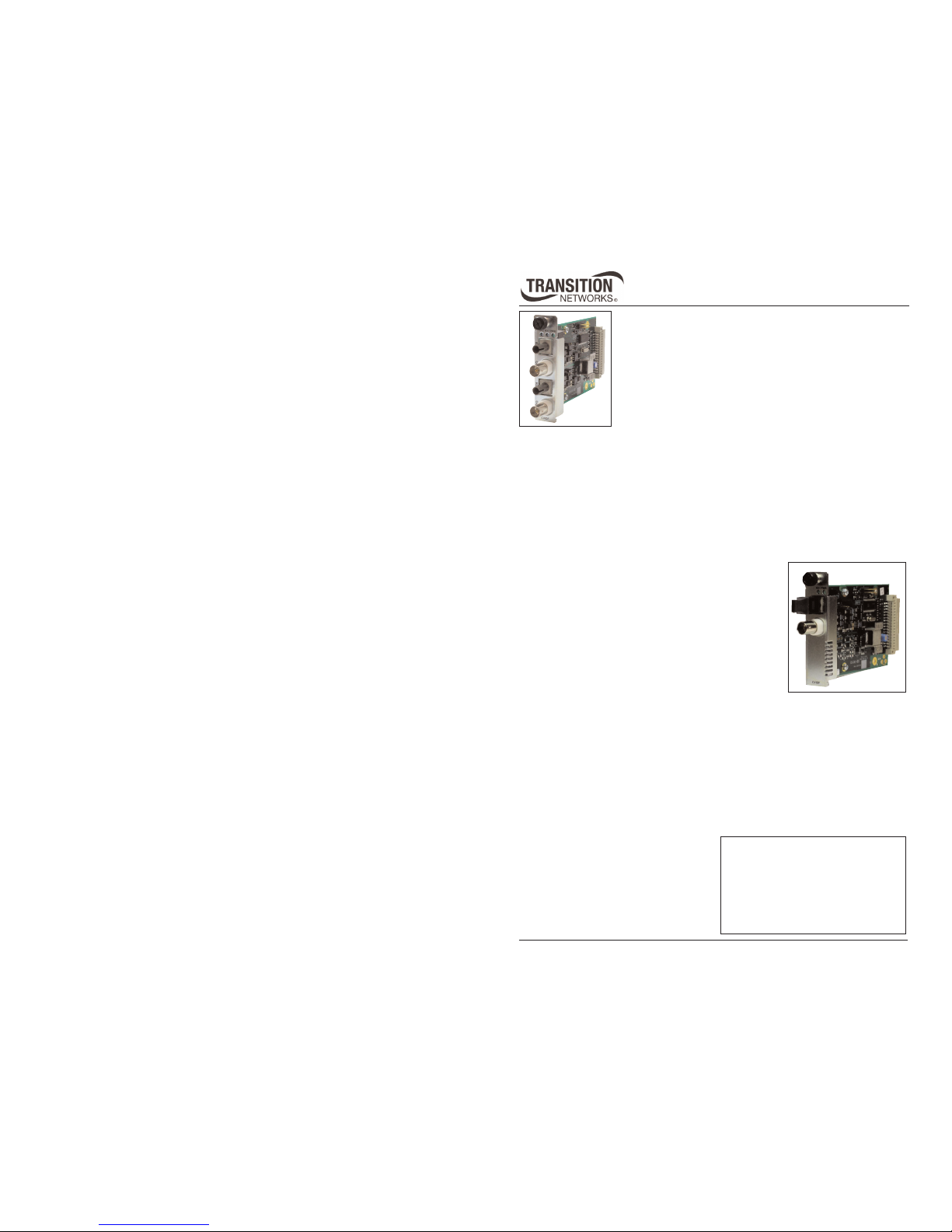
The chassis card is available in a single video channel or a
dual video channel configuration. All video conversion is
performed in real time. The automatic Gain Control (AGC)
feature automatically adjusts the video contrast and
brightness to maintain the quality and integrity of the
original video stream.
Dual
Single
Page 2

2
CVIDF20xx-15x
24-Hour Technical Support: 1-800-260-1312 -- International: 00-1-952-941-7600
Model Optic Fiber Distance
CVIDF2011-150
Video Receiver (Single)
ST, multimode, 850 nm 1km (0.6miles) standard
2km (1.2miles) extended
CVIDF2011-155
Video Receiver (Dual)
(2)ST, multimode, 850 nm 1km (0.6miles) standard
2km (1.2miles) extended
CVIDF2013-150
Video Receiver (Single)
SC, multimode, 850 nm 1km (0.6miles) standard
2km (1.2miles) extended
CVIDF2013-155
Video Receiver (Dual)
(2)SC, multimode, 850 nm 1km (0.6miles) standard
2km (1.2miles) extended
CVIDF2012-150
Video Receiver (Single)
ST, single mode, 1310 nm 10km (6.2miles) standard
20km (12.4miles) extended
CVIDF2012-155
Video Receiver (Dual)
(2)ST, single mode, 1310 nm 10km (6.2miles) standard
20km (12.4miles) extended
Connector Type Quantity Distance
75-Ohm BNC 2 75-Ohm coax cable, 228m (750ft)
Fiber 2 Model dependent (see below)
The video receiver system has the following types of connectors.
The various fiber connections are available on separate models. Single mode and
multimode receivers come in the following configurations.
Installation
Card handling
1. Keep the CVIDF20xx-15x card in its anti-static bag until ready to install.
2. Wear a grounding strap when removing the card from its anti-static bag.
Distance configuration shunt
The CVIDF20xx-15x card come with a shunt installed in the “S” position on connector
J1 (single channel) and J1/J5 (dual channel) as shown below.
CVIDF20xx-15x
Installation -- continued
J1 and J5 are distance configuration connectors. Position “S” is for standard distances
and “X” is for extended distances. The distances are model dependent.
Installing video card in a Point System chassis
To insert the video card, do the following:
1. Wearing a ground strap, slide the card into an available slot in the Point System
chassis. See photo below.
2. Push the card all the way into the slot (should snap in).
3. Push in and turn the screw clockwise to secure the card to the chassis frame.
3
Setting up the video system
Equipment needed:
• J/VD-TX-01 fiber transmitter (single or multimode)
• CVIDF20xx-15x video card (single or multimode)
• Video camera
• Monitor
• Coax cable
• Fiber cable
Note: The video transmitter and receiver must be matched: single mode TX/RX or
multimode TX/RX. If installed as a mixed pair, the system will not function.
Caution: Use 75 ohm BNC connectors on 75 ohm cable only. Failure to observe this
caution will result in signal degradation.
Note: See J/VD-TX-01 fiber transmitter manual (#33349) available on the web @
transition.com for specifics.
techsupport@transition.com -- Click the “Transition Now” link for a live Web chat.
Page 3

4
CVIDF20xx-15x
24-Hour Technical Support: 1-800-260-1312 -- International: 00-1-952-941-7600
Setting up video system -- continued
To install the video transmitter and receiver system cables, see installation diagram
below.
Point System
Chassis
with
CVIDF20xx-15x
Receiver Card
Fiber
Fiber
Dual Channel Video System
75-Ohm BNC Coax Cable
75-Ohm BNC Coax Cable
Directly Mounted Camera
Monitor
Monitor
J/VD-TX- 01
Transmitter
Coax*
Camera
Camera
J/VD-TX-01
Transmitter
*75-Ohm BNC Coax Ca ble
Operation
LEDs
The following shows LED locations and an explanation of each follows:
RX2 RX1 PWR
1
2
3
techsupport@transition.com -- Click the “Transition Now” link for a live Web chat.
5
CVIDF20xx-15x
Operation -- continued
LED Description
1
RX2 (Receive) ON solid green = fiber cable connect/receiving data
Off = No power or cable disconnected
2
RX1 (Receive) ON solid green = fiber cable connect/receiving data
Off = No power or cable disconnected
3
PWR (Power) ON Green Powered
OFF No Power
• Make sure that power is supplied to the transmitter, receiver, and camera,
with the monitor turned ON.
• The system is operational when the camera feed appears on the monitor.
Cable specifications
Coax cable
RG Type: RG-59, RG-6
Gauge: 18–25, single conductor
Impedance: 75 ohms
Distance: 228 M (750 ft) Max
Fiber
Single Mode 9/125μ
Multimode 62.5/125μ
Multimode
Wavelength: 850 nm
Link Budget: 6.0 db or 11.0 db
Single Mode
Wavelength: 1310 nm
Link Budget: 10.0 db or 15.0 db
Technical Specifications
Use 75-ohm BNC connectors on 75-ohm cable only.
Transition Networks models CVIDF20xx-15x video receiver specifications for
all six models.
Video formats: NTSC, PAL, SECAM
Video spec
Input Video: 0.5 to 2-volt pk-pk (75 ohms)
Bandwidth: 5 Hz - 10 MHz
Differential gain: < 5 %
Differential phase: < 5°
Tilt: < 1%
Signal/Noise Ratio: 60dB
Page 4

6
CVIDF20xx-15x
24-Hour Technical Support: 1-800-260-1312 -- International: 00-1--952-941-7600
Technical Specifications -- continued
Power consumption: Single card 2 watts; dual card 3 watts
Power supply: 12 V – chassis AC
Operating temperature: 0°C to 60°C (32°F to 140°F)
Storage temperature: -25°C to 85°C (13°F to 185°F )
Humidity: 5% to 95%, non-condensing
Altitude: 0 to 10,000 feet
Dimensions: 0.86”W x 5.0”D x 3.4”H (22 mm x 127 mm x 86 mm)
Warranty: Lifetime
The information in this user’s guide is subject to change. For the most up-to-date
information on the CVIDF20xx-15x video receiver, view the user’s guide on-line at:
www.transition.com.
Troubleshooting
If there are problems with the system setup or a system failure occurs, isolate and
correct the problem by determining the answers to the following questions and then
taking the indicated action:
1. Is the power LEDs ON on the receiver?
NO
• Is the power to the chassis ON?
• Is the card fully inserted ?
• Is the power on LED lit?
• Contact Technical Support: US/Canada: 1-800-260-1312, International: 00-1952-941-7600.
YES
• Proceed to step 2.
2. Are the RX LED lit on the receiver?
NO
• Check that the fiber cable SM/MM matches the transmitter and receiver set
SM/MM.
• Check the fiber-cable connections and condition of the fiber cable.
• Check for video signal at the transmitter coax port.
• Check the coax cable connection.
• Contact Technical Support: US/Canada: 1-800-260-1312, International: 00-1952-941-7600.
YES
• Contact Technical Support: US/Canada: 1-800-260-1312, International: 00-1952-941-7600.
CVIDF20xx-15x
techsupport@transition.com -- Click the “Transition Now” link for a live Web chat.
7
Declaration of Conformity
Name of Mfg: Transition Networks
6475 City West Parkway, Minneapolis MN 55344 U.S.A.
Model: CVIDF2011-150, CVIDF2011-155,CVIDF2013-150,
CVIDF2013-155, CVIDF2012-150, CVIDF2012-155 Video
Receivers
Part Number(s): CVIDF20xx-15x
Regulation: EMC Directive 89/336/EEC
Purpose: To declare that the CVIDF20xx-15x to which this declaration refers is in
conformity with the following standards:
CISPR 22:1997+A1:2000; EN 55022 Class A; EN 55024:1998+A1:2000 Class A; FCC
part 15 subpart B; CFR 21 subpart J
I, the undersigned, hereby declare that the equipment specified above conforms to the above
Directive(s) and Standard(s).
Contact Us
Technical support
Technical support is available 24 hours a day.
US and Canada: 1-800-260-1312
International: 00-1-952-941-7600
Transition now
Chat live via the Web with Transition Networks Technical Support.
Log onto www.transition.com and click the Transition Now link.
Web-based seminars
Transition Networks provides seminars via live web-based training.
Log onto www.transition.com and click the Learning Center link.
E-Mail
Ask a question anytime by sending an e-mail to our technical support staff.
techsupport@transition.com
Address
Transition Networks
6475 City West Parkway, Minneapolis, MN 55344, U.S.A.
telephone: 952-941-7600, toll free: 800-526-9267, fax: 952-941-2322
Sept, 2006
Stephen Anderson, Vice-President of Engineering Date
Page 5

8
Trademark notice
All trademarks and registered trademarks are the property of their respective owners.
Copyright restrictions
© 2003, 2005 Transition Networks.
All rights reserved. No part of this work may be reproduced or used in any form or by any means graphic, electronic, or mechanical - without written permission from Transition Networks.
Printed in the U.S.A 33354.A
CVIDF20xx-15x
Compliance Information
FCC Class A; EN55022 Class A; EN55024;
CE Mark
FCC regulations
This equipment has been tested and found to comply with the limits for a class A digital device,
pursuant to part 15 of the FCC rules. These limits are designed to provide reasonable protection
against harmful interference when the equipment is operated in a commercial environment. This
equipment generates, uses, and can radiate radio frequency energy and, if not installed and used in
accordance with the instruction manual, may cause harmful interference to radio communications.
Operation of this equipment in a residential area is likely to cause harmful interference, in which
case the user will be required to correct the interference at the user's own expense.
Canadian regulations
This digital apparatus does not exceed the Class A limits for radio noise for digital apparatus set out
on the radio interference regulations of the Canadian Department of Communications.
Le présent appareil numérique n'émet pas de bruits radioélectriques dépassant les limites applicables
aux appareils numériques de la class A prescrites dans le Règlement sur le brouillage
radioélectrique édicté par le ministère des Communications du Canada.
European regulations
WARNING: This is a Class A product. In a domestic environment this product may cause radio
interference in which case the user may be required to take adequate measures.
ACHTUNG!
Dieses ist ein Gerät der Funkstörgrenzwertklasse A. In Wohnbereichen können bei
Betrieb dieses Gerätes Rundfunkstörungen auftreten. In diesem Fäll ist der Benutzer für
Gegenmaßnahmen verantwortlich.
ATTENTION!
Ceci est un produit de Classe A. Dans un environment domestique, ce produit
risque de créer des interférences radioélectriques, il appartiendra alors à l'utilsateur de prende les
measures spécifiques appropriées.
In accordance with European Union Directive 2002/96/EC of the European Parliament
and of the Council of 27 January 2003, Transition Networks will accept post usage returns
of this product for proper disposal. The contact information for this activity can be found
in the 'Contact Us' portion of this document.
CAUTION: RJ connectors are NOT INTENDED FOR CONNECTION TO THE
PUBLIC TELEPHONE NETWORK. Failure to observe this caution could result in
damage to the public telephone network.
Der Anschluss dieses Gerätes an ein öffentlickes Telekommunikationsnetz in den EGMitgliedstaaten verstösst gegen die jeweligen einzelstaatlichen Gesetze zur Anwendung der
Richtlinie 91/263/EWG zur Angleichung der Rechtsvorschriften der Mitgliedstaaten über
Telekommunikationsendeinrichtungen einschliesslich der gegenseitigen Anerkennung ihrer
Konformität.
 Loading...