

Transition Networks CGETF1014-110, CGETF1024-110, CGETF1015-110, CGETF1017-110, CGETF1035-110 User Manual
...Page 1
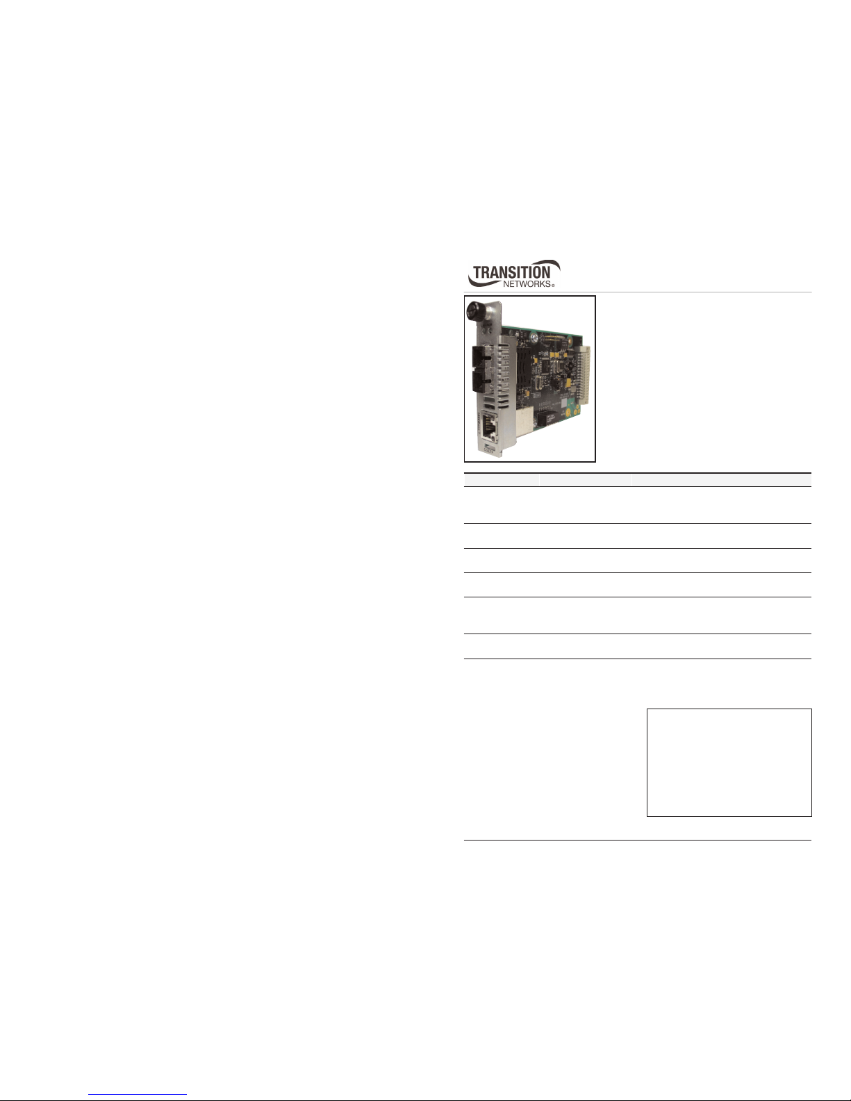
User’s Guide
CGETF10xx-1xx
Slide-in-Module Media Converter
• Gigabit Ethernet
• Copper to Fiber
• 1000Base-T to 1000Base-SX/LX
Transition Networks CGETF10xx-1xx Gigabit
Ethernet media converter connects 1000Base-T
shielded or unshielded twisted-pair copper cable to
1000Base-SX or 1000Base-LX, fiber-optic cable.
The CGETF10xx-1xx is designed to be installed in
the Transition Networks PointSystem™ chassis.
Installation . . . . . . . . . . . . . . . . . .4
Operation . . . . . . . . . . . . . . . . . . .7
Diagnostic Monitoring Interface
(DMI) . . . . . . . . . . . . . . . . . . . . .10
Cable Specifications . . . . . . . . . .11
Technical Specifications . . . . . . .13
Troubleshooting . . . . . . . . . . . . .14
Contact Us . . . . . . . . . . . . . . . . .15
Compliance Information . . . . . . .16
Part Number Port One - Copper Port Two - Duplex Fiber-Optic
CGETF1013-110
RJ-45 1000Base-T
100 m (328 ft)*
SC, 1000Base-SX, 850 nm multimode
220 m (721 ft)* (62.5/125 μm cable)
550 m (1,804 ft)* (50/125
μm cable)
CGETF1014-110
RJ-45 1000Base-T
100 m (328 ft)*
SC, 1000Base-LX, 1310 nm single mode
10 km (6.2 miles)*
CGETF1015-110
RJ-45 1000Base-T
100 m (328 ft)*
SC, 1000Base-LX, 1310 nm single mode
25 km (15.5 miles)*
CGETF1017-110
RJ-45 1000Base-T
100 m (328 ft)*
SC, 1000Base-LX, 1550 nm single mode
65 km (40.4 miles)*
CGETF1024-110
RJ-45 1000Base-T
100 m (328 ft)*
SC, 1000Base-SX, 1310 nm extended
multimode, 2 km (1.2 miles)*
Note: 62.5/125
μm (fiber only)
CGETF1035-110
RJ-45 1000Base-T
100 m (328 ft)*
SC, 1000Base-LX, 1550 nm single mode
125 km (77.5 miles)*
*Typical maximum cable distance. Actual
distance is dependent upon the physical
characteristics of the network installation.
Note: The stand-alone version of the media
converter is SGETF10xx-1xx. For
more information, see the
SGETF10xx-1xx user’s guide on-line
at: www.transition.com.
Page 2

2
CGETF10xx-1xx
24-hour Technical Support: 1-800-260-1312 International: 00-1-952-941-7600
Part Number Port One - Copper Port Two - Single Fiber-Optic
CGETF1040-110
RJ-45 1000Base-T
100 m (328 ft)*
SFP slots, see page 3 for SFP options.
CGETF1029-110
RJ-45 1000Base-T
100 m (328 ft)*
SC, 1000Base-LX, 1310 TX/1550 RX
single mode, 20 km (12.4 miles)*
CGETF1029-111
RJ-45 1000Base-T
100 m (328 ft)*
SC, 1000Base-LX, 1550 TX/1310 RX
single mode, 20 km (12.4 miles)*
The CGETF1029-110 and the CGETF1029-111 are to be installed in
the same network, where one is the local converter and the other is
the remote converter.
CGETF1029-112
RJ-45 1000Base-T
100 m (328 ft)*
SC, 1000Base-LX, 1310 TX/1550 RX
single mode, 40 km (24.8 miles)*
CGETF1029-113
RJ-45 1000Base-T
100 m (328 ft)*
SC, 1000Base-LX, 1550 TX/1310 RX
single mode, 40 km (24.8 miles)*
CGETF1029-116 RJ-45 1000Base-T
100 m (328 ft)*
SC, 1000Base-LX, 1510 TX/1590 RX
single mode, 80 km (49.7 miles)*
CGETF1029-117 RJ-45 1000Base-T
100 m (328 ft)*
SC, 1000Base-LX, 1590 TX/1510 RX
single mode, 80 km (49.7 miles)*
The CGETF1029-112 and the CGETF1029-113 are to be installed in
the same network, where one is the local converter and the other is
the remote converter.
techsupport@transition.com -- Click the “Transition Now” link for a live Web chat.
3
*Typical maximum cable distance. Actual distance is dependent upon the physical
characteristics of the network.
Note: Third-party Multi-Source Agreement (MSA) compliant Small Form Factor
Pluggables (SFPs) can also be used in the CGETF1040-11x.
Sold separately, the following DMI supported SFP transceiver modules for port two
are compatible with the CGETF1040-1xx converter and are available from Transition
Networks.
CGETF1040-110 Port One - Copper 1000-Base-TX
RJ-45 100 m (328 ft)
Part Number
CGETF1040-110
Port Two - Fiber-Optic 1000Base-SX/LX
TN-SFP-SX
LC, 1000Base-SX, 850 nm multimode, 220-550 mm (720-1804 ft)*
Without DMI
TN-SFP-SXD
LC, 1000Base-SX, 850 nm multimode, 220-550 mm (720-1804 ft)*
TN-SFP-LX1
LC, 1000Base-LX, 1310 nm single mode, 10 km (6.2 miles)*
TN-SFP-LX3
LC, 1000Base-LX, 1310 nm single mode, 30 km (18.8 miles)*
TN-SFP-LX5
LC, 1000Base-LX, 1550 nm single mode, 50 km (31.2 miles)*
TN-SFP-LX8
LC, 1000Base-LX, 1550 nm single mode, 80 km (50.0 miles)*
TN-SFP-LX12
LC, 1000Base-LX, 1550 nm single mode, 120 km (74.6miles)*
DMI Models (-1xx)
The Diagnostic Monitoring Interface (DMI) models (listed below) allow diagnosing
problems within the network. These devices have four functions:
• Transmit power
• Receive power
• Transmit bias current
• Temperature
Within each function, the device will send a trap; i.e., error whenever a high or low
warning event, or high or low alarm event occurs (for a total of 16 traps).
In addition, if both the local and remote media converters are DMI models, the device
will distinguish whether the trap event is from a local or a remote device.
DMI Supported SFPs
Page 3
4
CGETF10xx-1xx
24-hour Technical Support: 1-800-260-1312 International: 00-1-952-941-7600
Installation
CAUTION: Wear a grounding device and observe electrostatic discharge precautions
when setting the jumper, the 6-position switch, and installing the CGETF10xx-10x
media converter into the PointSystem™ chassis. Failure to observe this caution could
result in damage to the media converter.
Set the 2-position jumper
• The jumper is located on the media converter circuit board, connector J5.
• Use a small needle-nosed pliers or similar device to set the jumper.
• Refer to the illustration on the right for hardware/software jumper positioning.
Hardware The media converter’s mode of operation is
determined by the 6-position switch
settings. Default is the Hardware position.
Software The media converter’s mode of operation is
determined by the most recently saved onboard microprocessor settings.
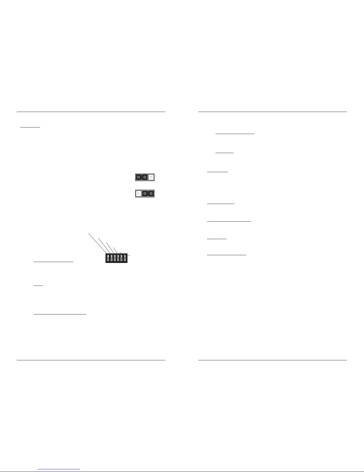
Set the 6-position switch
• The 6-position switch is located on the side of the media converter.
• Use a small flat-blade screwdriver to set the DIP switches.
• All switches are shown in the
default position, UP.
Note: Switch positions S2 and S3
function together to configure
the media converter for Pause
conditions.
S1 Remote-Fault Detection
up Disabled
down Enable
S2 & S3 work in combination
Pause
10 sw position 2 up and 3 down: Symmetric
01 sw position 2 down and 3 up: Asymmetric
11 sw positions 2 and 3 up: Pause is OFF (default position)
00 sw positions 2 and 3 down: Symmetric and Asymmetric
S4 Transparent Link Pass-Through
up Enable Link Pass-Through
down Disable Link Pass-Through
H
Software Mode
S
H
Hardware Mode
S
2. Pause (symmetric)
3. Pause (asymmetric)
4. Transparent Link Pass-Through
5. Auto-Negotiation
1. Remote Fiber Fault Detect
6. Loop Back
techsupport@transition.com -- Click the “Transition Now” link for a live Web chat.
5
Installation -- Continued
Set the 6-position switch -- continued
S5 Fiber Auto-Negotiation
up Disable Auto-Negotiation for the fiber link (default setting)
down Enable Auto-Negotiation for the fiber link
S6 Loop Back
up Disable RX/TX signal loop back (default setting)
down Enable RX/TX signal loop back
Install Mode
During installation, set DIP switch 4 DOWN; leave all other switches in the UP
position (default). This disables Transparent Link Pass-Through and AutoNegotiation, allowing individual copper and fiber links to be established (both
copper port LEDs will turn ON with each device-to-device connection) independent
of having a complete end-to-end connection.
Operation Mode
After installation is complete (all copper and fiber ports connected and linked), set
all switches to the UP position (default).
Remote Fiber Fault Detect
Remote fiber fault detect (RFD) monitors the status of the fiber link. Enable RFD in
the remote converter only.
CAUTION:
If RFD is enabled in the device at each end of the link, a link passthrough event will put the converters into an unrecoverable state (unable to
establish a link).
Fiber Auto-Negotiation
Fiber Auto-Negotiation allows the fiber interface to detect and then advertise the
supported features of the remote device—active only when a fiber cable is
connected to a device with a negotiating port. The process is as follows:
1. The fiber interface detects the supported features of the remote partner.
2. These abilities are passed to the twisted-pair interface and advertised.
3. Once the twisted-pair interface has a link at the highest common capability, it
passes the result to the fiber interface.
4. The fiber interfaces then start advertising these capabilities. At this point, the
link between the fiber and the negotiating port is complete.
If the CGETF10xx-1xx is connected via fiber to another CGETF10xx-1xx, both
media converters must have the Fiber Auto-Negotiation setting disabled (switch 5
UP).
Note: Transparent Link Pass-Through (switch position 4 enabled) cannot be
turned OFF (disabled) when Fiber Auto-Negotiation is ON (enabled).
Page 4

6
CGETF10xx-1xx
24-hour Technical Support: 1-800-260-1312 International: 00-1-952-941-7600
Installation -- Continued
Install the slide-in-module
IMPORTANT: Slots in the PointSystem™ chassis without a slide-in-module
installed MUST have a protective plate covering the empty slot for Class A
compliance.
To install the CGETF10xx-1xx media converter slide-in-module:
1. Locate an empty slot on the PointSystem™ chassis.
2. Carefully slide the slide-in-module into the slot, aligning it with the slot
guides.
3. Ensure that the slide-in-module is firmly seated inside the chassis.
4. Push in and rotate the panel fastener screw shown below clockwise to secure
the module to the chassis front.
Install the fiber cable
1. Locate a 1000Base-SX/LX compliant fiber cable with male, two-stranded TX
to RX connectors installed at both ends.
2. Connect the fiber cable to the CGETF10xx-1xx media converter as described:
• Connect the male TX cable connector to the female TX port.
• Connect the male RX cable connector to the female RX port.
3. Connect the fiber cables to the other device (another media converter, hub,
etc.) as described:
• Connect the male TX cable connector to the female RX port.
• Connect the male RX cable connector to the female TX port.
Media Converter
Point System Chassis
Panel Fastener
Slot
RX
TX
TX
RX
Device
Device
techsupport@transition.com -- Click the “Transition Now” link for a live Web chat.
7
Installation -- Continued
Install the copper cable
1. Locate a 1000Base-T compliant copper cables with male, RJ-45 connectors
installed at both ends.
2. Connect the RJ-45 connector at one end of the cable to the RJ-45 port on the
CGETF10xx-1xx media converter.
3. Connect the RJ-45 connector at the other end of the cable to the RJ-45 port on
the other device (switch, workstation, etc.).
RJ-45 Port
Media Converter
RJ-45 Port
On other device
(workstation, switch, etc.)
Point System Chassis
Operation
Status LEDs
Use the status LEDs to monitor the CGETF10xx-1xx
media converter operation in the network.
PWR (Power) ON = Connected to external
AC power.
LKF (Fiber link) ON = Fiber Connection
RXC (Copper receive) Flashing = Receiving data
on the copper
link.
ON = Copper Link
connection
Duplex ON = Full
LKF PWR
TX
RX
1000Base-X 1000Base-T
Duplex LED
RXC LED
Page 5

8
CGETF10xx-1xx
24-hour Technical Support: 1-800-260-1312 International: 00-1-952-941-7600
Operation -- Continued
Remote-Fault Detect (RFD)
Remote-Fault Detect monitors the status of the fiber link. When enabled, remote
fault detection turns off the converter’s fiber transmission when the fiber receiver
goes down. RFD should only be enabled in the remote converter; if enabled in both,
a link pass-through event will cause an unrecoverable condition between the
converters.
Pause
The pause feature can improve network performance by allowing one end of the
link to signal the other to discontinue frame transmission for a set period of time to
relieve buffer congestion.
The pause feature can be set to one of four settings:
• Disable (i.e., no pause)
• Symmetrical pause
• Asymmetric TX (transmit) pause
• Asymmetric RX (receive) pause
Enable the pause feature if it is present on ALL network devices attached to the
media converter(s); otherwise, disable this feature.
Link Pass-Through
The Link Pass-Through feature allows the media converter to monitor both the fiber
and copper RX (receive) ports for loss of signal. Refer to the illustration below. For
example, in the event of a loss of an RX signal (1), the media converter will
automatically disable the fiber TX (transmit) signal (2), thus, “passing through” the
link loss (3). The far-end device is automatically notified of the link loss (4), which
prevents the loss of valuable data unknowingly transmitted over an invalid link.
AutoCross (always on)
The AutoCross feature allows either straight-through (MDI) or crossover (MDI-X)
cables to be used when connecting to 10Base-T, 100Base-TX, or 1000Base-T
devices, such as hubs, transceivers, or network interface cards (NICs). AutoCross
determines the characteristics of the cable connection and automatically configures
the unit to link up to its companion device regardless of the cable configuration.
4
1
Media
Converter A
Media
Converter B
Near-End
Device
Far-End
Device
original fault
on the co
pper link
media converter B
disables the co
pper link
media converter A
disables the fiber TX link
3
2
media converter B
loses the fiber RX link
techsupport@transition.com -- Click the “Transition Now” link for a live Web chat.
9
Operation -- Continued
Transparent Link Pass-Through
Transparent Link Pass-Through operates similar to Link Pass-Through with one
exception: the fiber link between the converters remains active. A signal is passed
through to the remote converter, causing it to shutdown the copper link, notifying
the end device of the link failure.
Auto-Negotiation
Auto-Negotiation enables automatic configuration to achieve the best possible
mode of operation over a link between devices. A device with this feature enabled
will broadcast its speed (10Mbs, 100Mbs, etc.) and duplex (half/full) capabilities to
another device with this feature, then negotiate the best mode of operation between
them—no user intervention required.
Fiber Auto-Negotiation
Fiber Auto-Negotiation allows the fiber interface to detect and then advertise the
support capabilities of the remote device. This only occurs when a fiber cable is
connected to a device with a negotiating port.
Loop Back
This diagnostic feature enables the media converter to loop back the signal from the
RX port to the TX port for testing and troubleshooting purposes. Test signals from a
bit-error test unit can then be inserted into either the copper or fiber link to test a
particular segment.
This type of diagnostic test can only be performed from the local to the remote
device with loop back enabled on the remote device.
SNMP
Use SNMP at an attached terminal or at a remote location to monitor the media
converter by monitoring:
• Copper and fiber link/receive status
• Hardware switch settings
• Receive error count
Also, use SNMP to enter network commands that:
• Enable/disable Remote Fault Fiber Detection
• Enable/disable Link Pass-Through
• Enable/disable Auto-Negotiation
• Symmetric pause
• Asymmetric TX (transmit) pause
• Asymmetric RX (receive) pause
• Disable pause
See the on-line documentation that comes with Transition Networks FocalPoint™
software for applicable commands and usage.
Page 6

10
CGETF10xx-1xx
24-hour Technical Support: 1-800-260-1312 International: 00-1-952-941-7600
Diagnostic Monitoring Interface (DMI)
The following DMI port screen and explanation table contains brief definitions of the
DMI support offered on Transition Networks SFP optical interfaces. For further
information, please see the help option on the CPSMM-xxx SNMP agent or Focal Point
GUI.
Variable Name Description
DMI Rx Power Measured Receive optical power in microwatts and in decibels
relative to 1mW.
DMI Rx Power Alarm Alarm status of measured Receive optical power.
DMI Temp Internally measured temperature of transceiver in degrees C and
degrees F.
DMI Temp Alarm Alarm status for internally measured temperature of transceiver.
DMI Bias Current Measured transmit bias current in microamperes.
DMI Bias Alarm Alarm status for measured transmit bias current for the
interface.
DMI Tx Power Measured transmit power, in microwatts and in decibels relative
to 1mW..
DMI Tx Power Alarm Alarm status of measured transmit power.
Rx Power Intrusion
Threshold
Instructs the converter to stop passing traffic when the receive
power drops below the new threshold. This feature is
sometimes referred to as 'Intrusion Detection, since tapping into
a fiber to intercept traffic leads to a reduction in receive power.
This value can be entered in microwatts or in decibels relative
to 1mW.
Note: This feature is not available on all devices.
techsupport@transition.com -- Click the “Transition Now” link for a live Web chat.
11
Cable Specifications
The physical characteristics must meet or exceed IEEE 802.3™ specifications.
Fiber cable
Bit Error Rate: <10-9
Single mode fiber (recommended):9 μm
Multimode fiber (recommended): 62.5/125 μm
Multimode fiber (optional): 100/140, 85/140, 50/125 μm
CGETF1013-110 850 nm multimode
Fiber Optic Transmitter Power: min: -10.0 dBm max: -4.0 dBm
Fiber Optic Receiver Sensitivity: min: -17.0 dBm max: 0.0 dBm
Link Budget: 7.0 dB
CGETF1014-110 1310 nm single mode
Fiber-optic Transmitter Power: min: -9.5 dBm max: -3.0 dBm
Fiber-optic Receiver Sensitivity: min: -20.0 dBm max: -3.0 dBm
Link Budget: 10.5 dB
CGETF1015-110 1310 nm single mode
Fiber-optic Transmitter Power: min: -5.0 dBm max: -0.0 dBm
Fiber-optic Receiver Sensitivity: min: -24.0 dBm max: -3.0 dBm
Link Budget: 19.0 dB
CGETF1017-110 1550 nm single mode
Fiber-optic Transmitter Power: min: -3.0 dBm max: 2.0 dBm
Fiber-optic Receiver Sensitivity: min: -24.0 dBm max: -3.0 dBm
Link Budget: 21.0 dB
CGETF1024-110 1300 nm extended multimode
Fiber-optic Transmitter Power: min: -10.0 dBm max: -3.0 dBm
Fiber-optic Receiver Sensitivity: min: -17.0 dBm max: -3.0 dBm
Link Budget: 7.0 dB
CGETF1035-110 1550 nm single mode
Fiber-optic Transmitter Power: min: 0.0 dBm max: 5.0 dBm
Fiber-optic Receiver Sensitivity: min: -27.0 dBm max: -3.0 dBm
Link Budget: 27.0 dB
CGETF1029-110 1310nm TX / 1550nm RX single mode
CGETF1029-111 1550nm TX / 1310nm RX single mode
Fiber-optic Transmitter Power: min: -8.0 dBm max: -3.0 dBm
Fiber-optic Receiver Sensitivity: min: -21.0 dBm max: -3.0 dBm
Link Budget: 13.0 dB
Page 7

12
CGETF10xx-1xx
24-hour Technical Support: 1-800-260-1312 International: 00-1-952-941-7600
Cable Specifications -- Continued
Fiber cable - Continued
CGETF1029-112 1310nm TX / 1550nm RX single mode
CGETF1029-113 1550nm TX / 1310nm RX single mode
Fiber-optic Transmitter Power: min: -3.0 dBm max: +2.0 dBm
Fiber-optic Receiver Sensitivity: min: -23.0 dBm max: -3.0 dBm
Link Budget: 20.0 dB
CGETF1029-116 1510nm TX / 1590nm RX single mode
CGETF1029-117 1590nm TX / 1510nm RX single mode
Fiber-optic Transmitter Power: min: -2.0 dBm max: +3.0 dBm
Fiber-optic Receiver Sensitivity: min: -26.0 dBm max: -3.0 dBm
Link Budget: 24.0 dB
Copper cable (Category 5 -- minimum requirement)
• Gauge = 24 to 22 AWG; Attenuation = 22.0 dB /100m @ 100 MHz
• Straight-through OR crossover cable may be used.
• Shielded twisted-pair (STP) OR unshielded twisted-pair (UTP) may be used
• All pin pairs (1&2, 3&6, 4&5, 7&8) are active in a gigabit network.
• Use only dedicated wire pairs for the active pins; e.g., blue/white & white/blue,
orange/white & white/orange, etc.
• Do not use flat or silver satin wire.
13
techsupport@transition.com -- Click the “Transition Now” link for a live Web chat.
Technical Specifications
For Transition Networks’ Model CGETF10xx-1xx or equivalent
Standards: IEEE 802.3ab™, IEEE 802.3 2000
Data Rate / Delay: 1000 Mbs/300 nsec
Dimensions: 3.4" x 1.0" x 5.0" (86mm x 25mm x 127mm)
Weight: 3 oz. (91 g) approximately
Power Consumption: 5.4W 450mA @ 12VDC
Packet Size: 10 Kbytes (maximum)
MTBF* 381,000 hours (MIL217F2 V5.0) (MIL-HDBK-217F)
1,344,000 hours (Bellcore7 V5.0)
Operating Temp: Tmar** 0°C to 50°C (32°F to 122°F)
Storage Temp: -15°C to 65°C (5°F to 149°F)
Humidity: 10% to 90%, non condensing
Altitude: 0 to 10,000 feet
Warranty: Lifetime
*MTBF is estimated using the predictability method. This method is based on MIL-217F at 25°C
ambient temperature, typical enclosure heat rise of 10°C, and nominal operating conditions and
parameters. Installation and configuration specific MTBF estimates are available upon request.
Contact Technical Support.
**Manufacturer’s rated ambient temperature.
For the most up-to-date information on the CGETF10xx-1xx media converter, view the user’s
guide on-line at: www.transition.com.
The fiber optic transmitters on this device meet Class I Laser safety requirements per IEC825/CDRH standards and comply with 21 CFR1040.10 and 21CFR1040.11.
WARNING:
Visible and invisible laser radiation when open. Do not stare into the beam or view
the beam directly with optical instruments. Failure to observe this warning could result in an eye
injury or blindness.
WARNING:
Use of controls, adjustments or the performance of procedures other than those
specified herein may result in hazardous radiation exposure.
IMPORTANT:
Copper based media ports, e.g., Twisted Pair (TP) Ethernet, USB, RS232,
RS422, RS485, DS1, DS3, Video Coax, etc., are intended to be connected to intra-building
(inside plant) link segments that are not subject to lightening transients or power faults. Copperbased media ports, e.g., Twisted Pair (TP) Ethernet, USB, RS232, RS422, RS485, DS1, DS3,
Video Coax, etc., are NOT to be connected to inter-building (outside plant) link segments that are
subject to lightening transients or power faults.
Page 8

14
CGETF10xx-1xx
24-hour Technical Support: 1-800-260-1312 International: 00-1-952-941-7600
Troubleshooting
If the media converter fails, isolate and correct the fault by determining the answers to
the following questions and then taking the indicated action:
1. Is the PWR (power) LED illuminated?
NO
• Is the media converter inserted properly into the chassis?
• Is the power cord installed properly in the chassis and at the external
power source and does the external power source provide power?
• Contact Tech Support: 1-800-260-1312, Int’l: 00-1-952-941-7600.
YES
• Proceed to step 2.
2. Is the RXC (copper link) LED illuminated?
NO
• Check the twisted-pair copper cables for proper connection.
• Contact Tech Support: 1-800-260-1312, Int’l: 00-1-952-941-7600.
YES
• Proceed to step 3.
3. Is the LKF (fiber link) LED illuminated?
NO
• Check the fiber cables for proper connection.
• Verify that the TX and RX cables on the media converter are connected
to the RX and TX ports, respectively, on the other device.
• If the converter is connected to another xGETF10xx-11x via fiber, make
sure that the Auto-Negotiation (DIP switch 5) is disabled (UP) in
hardware mode, or disabled via software in software mode.
• Contact Tech Support: 1-800-260-1312, Int’l: 00-1-952-941-7600.
YES
• Proceed to step 4.
4. Is the RXC (copper receive) LED flashing?
NO
• If there is activity on the 1000Base-T port, disconnect and reconnect the
twisted-pair copper cable to restart the initialization process.
• Restart the workstation to restart the initialization process.
• Contact Tech Support: 1-800-260-1312, Int’l: 00-1-952-941-7600.
YES
• Contact Tech Support: 1-800-260-1312, Int’l: 00-1-952-941-7600.
techsupport@transition.com -- Click the “Transition Now” link for a live Web chat.
15
Declaration of Conformity
Name of Mfg: Transition Networks
10900 City West Parkway, Minnetonka MN 55343 U.S.A.
Model: CGETF10xx-1xx Series Media Converters
Part Number(s): CGETF1013-110, CGETF1014-110, CGETF1015-110,
CGETF1017-110, CGETF1018-110, CGETF1024-110,
CGETF1035-110, CGETF1040-110, CGETF1029-110,
CGETF1029-111, CGETF1029-112, CGETF1029-113,
CGETF1029-116, CGETF1029-117
Regulation: EMC Directive 89/336/EEC
Purpose: To declare that the CGETF10xx-1xx to which this declaration refers is in
conformity with the following standards:
EN 55022:1994 + A1:1995 + A1:1997; EN 55024:1998 + Al:2001 + A2:2003
I, the undersigned, hereby declare that the equipment specified above conforms to the above
Directive(s) and Standard(s).
June, 2008___
Stephen Anderson, Vice-President of Engineering Date
Contact Us
Technical support
Technical support is available 24-hours a day
US and Canada: 1-800-260-1312
International: 00-1-952-941-7600
Transition now
Chat live via the Web with Transition Networks Technical Support.
Log onto www.transition.com and click the Transition Now link.
Web-based seminars
Transition Networks provides seminars via live web-based training.
Log onto www.transition.com and click the Learning Center link.
E-Mail
Ask a question anytime by sending an e-mail to our technical support staff.
techsupport@transition.com
Address
Transition Networks
10900 Red Circle Drive
Minnetonka, MN 55343, U.S.A.
telephone: 952-941-7600
toll free: 800-526-9267
fax: 952-941-2322
Page 9

Printed in the U.S.A. 33333.E
Trademark notice
All trademarks and registered trademarks are the property of their respective owners.
Copyright restrictions
© 2003-2005 Transition Networks.
All rights reserved. No part of this work may be reproduced or used in any form or by any means graphic, electronic or mechanical - without written permission from Transition Networks.
16
CGETF10xx-1xx
Compliance Information
CE Mark
FCC regulations
This equipment has been tested and found to comply with the limits for a Class A digital device,
pursuant to Part 15 of the FCC rules. These limits are designed to provide reasonable protection
against harmful interference when the equipment is operated in a commercial environment. This
equipment generates, uses and can radiate radio frequency energy and, if not installed and used in
accordance with the instruction manual, may cause harmful interference to radio communications.
Operation of this equipment in a residential area is likely to cause harmful interference, in which
case the user will be required to correct the interference at the user's own expense.
Canadian regulations
This digital apparatus does not exceed the Class A limits for radio noise for digital apparatus
set out on the radio interference regulations of the Canadian Department of Communications.
Le présent appareil numérique n'émet pas de bruits radioélectriques dépassant les limites applicables
aux appareils numériques de la Class A prescrites dans le Règlement sur le brouillage
radioélectrique édicté par le ministère des Communications du Canada.
European regulations
Warning
This is a Class A product. In a domestic environment this product may cause radio interference in
which case the user may be required to take adequate measures.
Achtung !
Dieses ist ein Gerät der Funkstörgrenzwertklasse A. In Wohnbereichen können bei Betrieb dieses
Gerätes Rundfunkstörungen auftreten. In diesem Fäll is der Benutzer für Gegenmaßnahmen
verantwortlich.
Attention !
Ceci est un produit de Classe A. Dans un environment domestique, ce produit risque de créer des
interférences radioélectriques, il appartiendra alors à l'utilsateur de prende les measures spécifiques
appropriées.
CAUTION: RJ connectors are NOT INTENDED FOR CONNECTION TO THE
PUBLIC TELEPHONE NETWORK. Failure to observe this caution could result in
damage to the public telephone network.
Der Anschluss dieses Gerätes an ein öffentlickes Telekommunikationsnetz in den EGMitgliedstaaten verstösst gegen die jeweligen einzelstaatlichen Gesetze zur Anwendung der
Richtlinie 91/263/EWG zur Angleichung der Rechtsvorschriften der Mitgliedstaaten über
Telekommunikationsendeinrichtungen einschliesslich der gegenseitigen Anerkennung ihrer
Konformität.
In accordance with European Union Directive 2002/96/EC of the European Parliament
and of the Council of 27 January 2003, Transition Networks will accept post usage returns
of this product for proper disposal. The contact information for this activity can be found
in the 'Contact Us' portion of this document.
 Loading...