

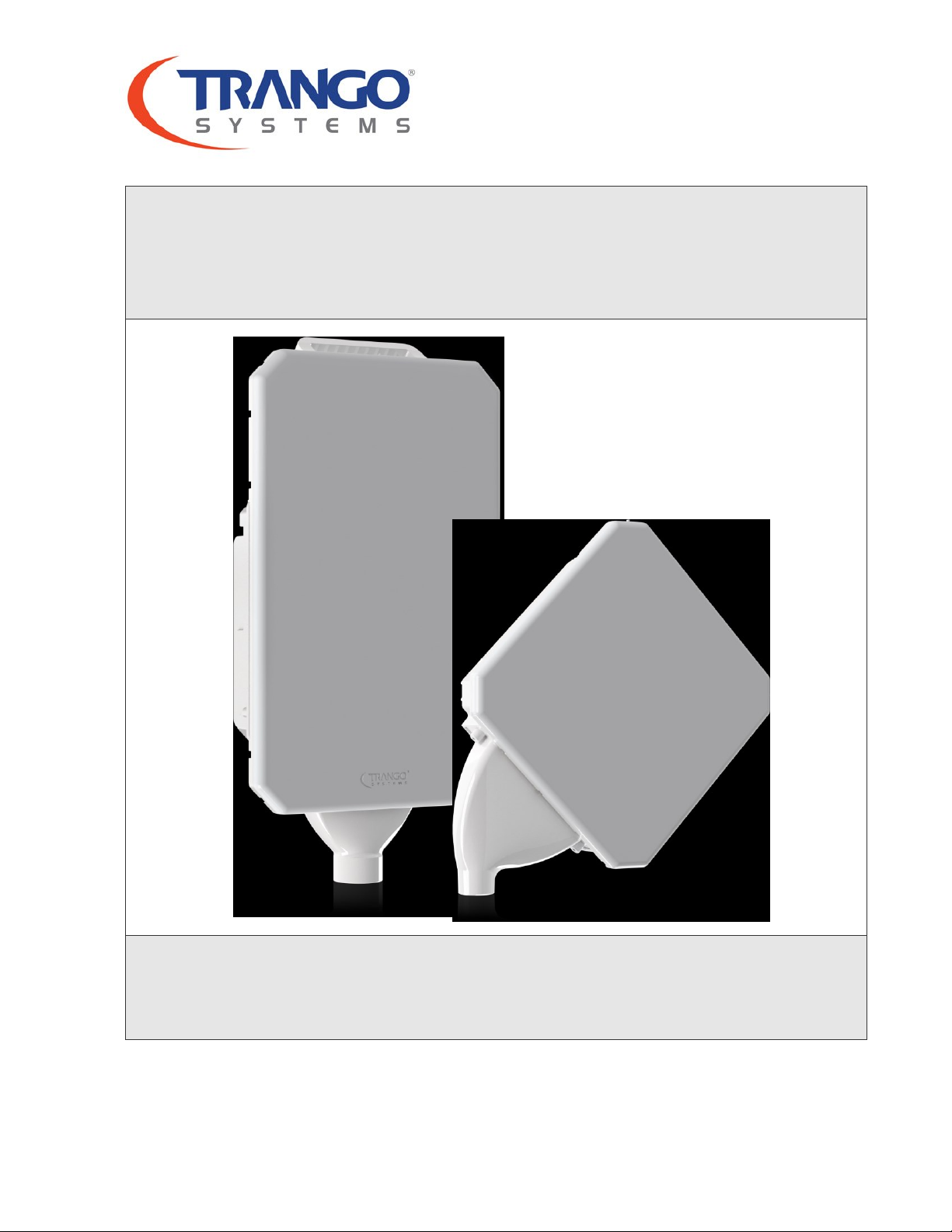
StrataPro
®
24
24 GHz All-Outdoor 1-4 Gbps FDD Point to Point License-Free Microwave System
Models: SP24-SI, SP24-XI
Quick Start Guide

Notice
This document contains information that is confidential and proprietary to Trango
Systems, Inc. No part of the content of this publication may be reproduced, modified,
used, copied, disclosed, conveyed, or distributed to any party in any manner whatsoever
without prior written authorization from Trango Systems, Inc. This document is provided
as is, without warranty of any kind.
Trademarks
Trango Systems®, StrataPro®, StrataPro®, and TrangoLINK Giga
®
are registered trademarks
of Trango Systems, Inc. Other names mentioned in this publication are owned by their
respective holders.
Statement of Conditions
The information contained in this document is subject to change without notice. Trango
Systems, Inc. shall not be liable for errors contained herein or for incidental or
consequential damage in connection with the furnishing, performance, or use of this
document or equipment supplied with it.
Information to User
Any changes or modifications of equipment not expressly approved by the
manufacturer could void the user’s authority to operate the equipment and the
warranty for such equipment.
Trango Systems, Inc.
14118 Stowe Drive, Suite B
Poway, CA 92064
Tel.: +1 (858) 391-0010
Fax: +1 (858) 391-0020
Copyright © 2016 by Trango Systems, Inc. All rights reserved.
Document Number LT-9074 Rev A
Trango Systems, Inc. StrataPro 24 Quick Start Guide 2
Introduction
Part Number
Description
TLSP-24-SI
StrataPro® 24 US/IC system, Single Carrier 24.05-24.25 GHz
TLSP-24-XI
StrataPro® 24 US/IC system, XPIC Dual Carrier 24.05-24.25 GHz
SP24-SI
StrataPro® 24 All Outdoor Unit, Single Carrier US/IC 24.05-24.25 GHz
SP24-XI
StrataPro® 24 All Outdoor Unit, XPIC Dual Carrier US/IC 24.05 -24.25 GHz
SP24-SI-N
StrataPro® 24 All Outdoor Unit, Single Carrier NCC 24.00 -24.25 GHz
SP24-XI-N
StrataPro® 24 All Outdoor Unit, XPIC Dual Carrier NCC 24.00-24.25 GHz XPIC
PSUPPLY-WM-48-2
+48 VDC/1.8A Volt Direct Power Supply with Terminal Blocks
POE-GIGE-P56
Passive Gigabit +56V/56W PoE
POE-GIGE-AT60
802.3at Active Gigabit +56V/60W PoE w/Surge/Lightning Suppressor
CBLDAT-RSSI
BNC-M to Banana plug cable for RSSI voltage measurement
CBLDAT-MIMO-9
MIMO Coaxial Cable set (2ea 9 ft SMA cables) – 2 sets required per link
SP-KEY-1G
Software Key to enable 1100 Mbps Capacity for one pair of radios
SP-KEY-2G
Software Key to enable 2200 Mbps Capacity for one pair of radios
SP-KEY-A256
Software Key to enable AES 256 for one pair of radios
SP-KEY-CE
Software Key to enable Carrier Ethernet Features
SFP-Console
Serial Console SFP Module with DB9 Male Serial Interface
SFP-GigE-C-1
SFP 100/1000BaseT Copper RJ45
SFP-GigE-S
SFP Fiber Single Mode Module
SFP-GigE-M
SFP Fiber Multi Mode
CBLDAT-RIU5
1+1 HSB cable (45 in)
Thank you for purchasing the StrataPro 24 unlicensed point to point microwave system.
This guide is designed to assist with basic installation and configuration of the system.
For advanced settings, refer to the User Manual and application notes.
System Components
The basic link consists of the following items:
2 each all outdoor radio model SP24 radios.
2 each +56VDC PoE Injector (required only if Power over Ethernet is used)
2 each pole mount kits
Cat5e/Cat6 shielded cabling with shielded plugs as needed.
Additional items may be needed depending on the link configuration. A List of the most
common part numbers used for the system is given in Table 1.
Table 1: StrataPro® 24 Part Numbers
Trango Systems, Inc. StrataPro 24 Quick Start Guide 3
Radio Unit Overview
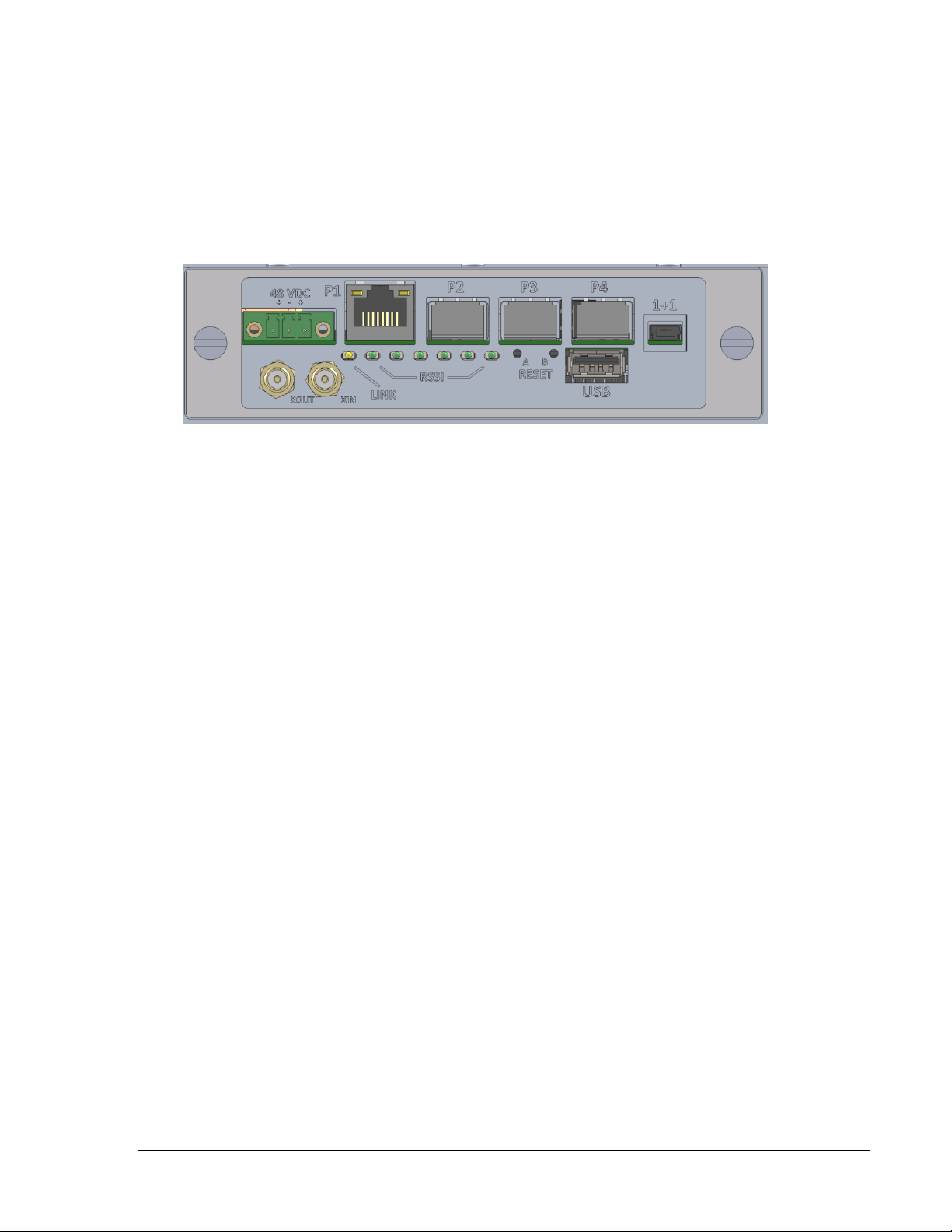
Below is a picture showing the main interfaces of the SP24 after removing the port
cover (loosen the two captive thumbscrews)
User Interfaces
P1 (RJ45) – Port 1 Ethernet Interface for Traffic and Management (Default).
Autonegotiate 100/1000 BaseT. This port also supports PoE operation using the POEGIGE-56 Power Injector. This is the default traffic and management port.
P2 (SFP) - Port 2 Ethernet Interface for Traffic and Management. Autonegotiate
100/1000 BaseT for Copper SFP and 1000 Base-X or 2500 Base-X for Fiber. Use only
Trango approved SFP modules.
P3 (SFP) - Port 3 Ethernet Interface for Traffic and Management. Autonegotiate
100/1000 BaseT for Copper SFP and 1000 Base-X for Fiber. Use only Trango approved
SFP modules. With the optional SFP-Console cable this port can be directly connected
to a PC Serial port.
P4 (SFP) - Port 4 Ethernet Interface for Traffic and Management. Autonegotiate
100/1000 BaseT for Copper SFP and 1000 Base-X for Fiber. . Use only Trango approved
SFP modules.
NOTE: DO NOT CONNECT POE to SFP ports AS THE SFP MODULE WILL BE DAMAGED
48VDC - Direct Power Terminal Block for applying direct +48 VDC nominal power to the
unit. Usable range is +43 to +57 VDC
Trango Systems, Inc. StrataPro 24 Quick Start Guide 4
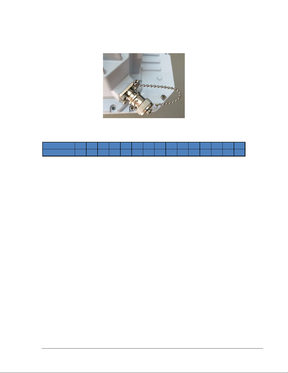
BNC – Output of DC voltage proportional to the RSSI level. The chart below gives the
RSL(dBm) -90 -85 -80 -75 -70 -65 -60 -55 -50 -45 -40 -35 -30 -25 -20
BNC Voltage (V) 0.10 0.30 0.50 0.70 0.90 1.10 1.30 1.50 1.70 1.90 2.10 2.30 2.50 2.70 2.90
voltage vs RSL.
BNC Connector w/Cap
The BNC Voltage = 0.1 +0.04 x (90+RSL) Volts, where RSL = -90 to -20 dBm
Reset A/B – The Reset buttons (recessed in the hole) operate as described below – Note
that all LEDs will blink on/off once per second while holding as a way to count the
seconds elapsed.
1) Hold for more than 3 seconds, but less than 6 seconds
a. The IP address will be reset to defaults based on button
i. 192.168.100.100 for Reset “A”
ii. 192.168.100.101 for Reset “B”
b. The CLI management passwords will be reset to default
c. The Web interface passwords will be reset to default.
d. The SNMP read/write/trap community strings will be set to defaults.
e. The CLI prompt will be reset.
2) Hold for more than 6 seconds: The unit will reset the system configuration to
the factory defaults, but NOT reset the items in (1) above. The unit WILL
REBOOT automatically.
a. The TX and RX Frequencies will be reset to allow a link to be established
as follows:
i. TX/RX Frequency of 24.1/24.2 GHz for Reset “A”
ii. TX/RX Frequency of 24.2/24.1 GHz for Reset “B”
Trango Systems, Inc. StrataPro 24 Quick Start Guide 5

Link LED – Green LED is solid on when linked with the far end unit, and Flashing when
not linked. LED will be solid at system power up for up to 2 minutes.
RSSI LEDs – Amber LEDs are lit up based on the M1 RSSI according to the following
table:
0 LEDs: RSSI < -65 dBm
1 LED: RSSI > -65 dBm
2 LEDs: RSSI > -60 dBm
3 LEDs: RSSI > -55 dBm
4 LEDs: RSSI > -50 dBm
5 LEDs: RSSI > -45 dBm
6 LEDs: RSSI > -40 dBm
Xin/Xout (XI model only) – Input/Output coaxial connection to second MIMO radio for
use in 4x4 MIMO configuration –Radios must be spaced at the optimum distance for
proper operation (See manual for details). CBLDAT-MIMO-9 kit required for spacings up
to 3 meters. Connect Xin to Xout on second radio.
USB Port – Reserved for Future Use - Do not connect
1+1– 1+1 Hot Standby port for monitoring connection to Hot Standby Radio. The
Standby unit should be as close as possible to the Active Unit and aligned with the far
end. CBLDAT-RIU5 cable required for each end of link.
Note that this cable carries monitoring information for the Standby unit to determine if
the Active unit is operating properly. If the cable is removed during operation then the
Standby will activate. Ensure that the cable is securely installed. See Full User Manual for
more details.
Trango Systems, Inc. StrataPro 24 Quick Start Guide 6

Radio Management
There are three ways to manage the StrataPro System:
1) In-Band Management (IBM) without a VLAN using the management port (default
P1). Only traffic coming into the radio from management port or the RF with the
Radio MAC address will be forwarded to the CPU and all other traffic will be
forwarded to over the link. This is the default configuration.
2) In- Band Management (IBM) with a VLAN using the management port (default
P1). . Only traffic coming into the radio on the management port or the RF with
a matching VLAN ID and the Radio MAC address will be forwarded to the CPU. All
other traffic will be forwarded over the link. The VLAN tagging option must be
enabled and the VLAN ID set.
3) Out- of- Band Management (OBM). The system will pass management traffic
coming into the OBM port to the CPU and not forward any traffic across the link
from this port. Disable IBM to enable OBM on the current management port.
Using the web interface is the easiest way to set up the system. Both sides of the link
can be set via a web session with only one radio.
Management of the radio may be done via the following interfaces:
1) Web Browser
2) Telnet
3) SSH
4) Console port
This Quick Start Guide covers the basic Web based setup. For other interfaces, please
read the User Manual.
The radio has two levels of access, View and Config. View allows only viewing of the
various parameters while config allows changing them. The default login and passwords
for each level are:
View Level Login: admin
Password: trango
Config Level Login: config
Password: trango
Trango Systems, Inc. StrataPro 24 Quick Start Guide 7

WEB BROWSER SETUP
The best performance is obtained using Google Chrome as the browser.
When using the web in config mode, changes can be entered and changed on the link by
pressing the “Apply Changes” button. The changes will take effect immediately but will
not be saved to FLASH memory. If a reboot is performed, the last saved configuration of
the system will be reloaded.
To permanently save the changes after verifying the changes, press the “Save Changes”
button. This will overwrite the configuration file in FLASH so that the next time the
radio is rebooted the changes will take effect.
When purchased as a link, one radio will be programmed with the IP address
192.168.100.100 and the other will be 192.168.100.101. The radios are setup with a
default 100 MHz channel bandwidth with IBM enabled on Port 1. Traffic can be carried
on any port over the link.
After logging into the config level and selecting the Link Setup Page, the IP address,
Netmask, and Gateway should be changed as appropriate for both radios. Press the
“Save Changes” button to the left to save the IP address. When properly linked the
display should show the locked indications at the top of each page.
Trango Systems, Inc. StrataPro 24 Quick Start Guide 8

INSTALLATION REQUIREMENTS
TOOLS
- Flat head Screwdriver for port cover attachment
- 13 mm or ½” Socket wrench for standard mount assembly
- 8 mm or 5/16” Socket wrench for attaching radio to mount and ground lug.
- Multimeter with CABLDAT-RSSI for antenna alignment
PATH
- Line of sight (LOS) with no obstructions in the Fresnel Zone
-
MOUNTING STRUCTURE
- Building or 1.5 to 3 inch diameter pole with < 1.5 degrees vertical or horizontal
movement under windload.
- Radios must be mounted at least 8 feet off the ground for best performance
POWER
- 110 or 240 VAC if using PoE Adapter
- +43 to +57 VDC/1.5 Amp Regulated Power Supply if using direct input
GROUNDING
- Min 10 AWG grounding cable with #10 Spade Lug, maximum length 1 m/3 feet
CABLING
- Cat 5e or Cat6 Shielded Twisted pair with shielded plugs. The cable shield should
be electrically connected to the plug shell. If using PoE the cable to the radio
should be no longer that 250 feet total.
SYSTEM CONFIGURATION:
The radios come preconfigured from the factory and will link up with no change to user
settings. The only change that must be made is to set the static IP address of the radios.
Follow the steps below to set the IP address and verify the RF link before installation.
1) Apply power using the PoE or with direct power (+56VDC)
2) Set up a Personal computer which has it’s local IP and subnet mask set as
follows:
IP: 192.168.100.10
Subnet: 255.255.255.0
Gateway: 192.168.100.1
Trango Systems, Inc. StrataPro 24 Quick Start Guide 9

3) Connect the PC Ethernet to the PoE injector Data In port and verify the Ethernet
link comes up.
4) Log into either Radio unit using a browser using the default IP addresses of
192.168.100.100/192.168.100.101 with the following credentials:
user: admin password: trango
Log In Page
5) Navigate to the Link Info page as shown below.
The Link Info page shown below displays the current radio IP settings and RF
settings for the link. If the link is locked then the remote side information will be
shown. To make changes to the current settings, click the Config Mode button to
log into Config Mode.
Trango Systems, Inc. StrataPro 24 Quick Start Guide 10

6) Log into the Config Mode with the following credentials:
user: config password: trango
7) After entering config mode select Link> Management to go to the IP settings
page.
Trango Systems, Inc. StrataPro 24 Quick Start Guide 11

8) If the RF link is locked, both the local and remote radio IP settings can be
changed from the same page at the same time. Click the Remote Config Mode
button to “ON”, then click Apply Changes button. Navigate to the Management
Page. The Remote IP should now be modifiable. Set both the local and remote IP
settings as desired and click Apply Changes button again. If the link is not locked
then each radio IP can be set individually via a separate browser session.
Trango Systems, Inc. StrataPro 24 Quick Start Guide 12

FIELD INSTALLATION:
Letter “R”
1) Install the pole mount to the back of the StrataPro Unit using the 4 #10-32
Bolts/lockwashers and install on pole as shown below. Install the radio to the
mount first.
2) Attach the StrataPro 24 Unit + Mount to the mounting pole (3 inch diam typical)
with “R” indicator at the 12 O’Clock position - Adjust the mounting bolts to
ensure that the bubble level is centered. This unit will be transmitting Right Slant
Polarization and receiving Left Slant Polarization from the perspective of the
installer. IMPORTANT: Install the far end unit exactly the same way, with the
“R” at the top. Because this system uses slant polarization, the units will be
cross polarized.
3) If it is desired to use Left Slant Polarization, the “L” should be oriented at the 12
O’Clock position on BOTH ENDS. Typically this will not be necessary unless
multiple links are co-located.
Trango Systems, Inc. StrataPro 24 Quick Start Guide 13

4) Install the ground wire to earth ground on the pole or building structure. Use a
minimum 10 AWG grounding cable with #10 Spade Lug, maximum length 1 m/3
feet
5) Run the Ethernet/PoE Cable through the port cover/cord grip as shown below
then connect to the radio Port 1 (Built In RJ45).
6) Power up the radio by first plugging the cable into the PoE Unit, then plugging
the PoE unit into the AC power source. Connect the Data Port of the PoE on one
radio to a laptop computer or switch.
7) Align the radios using the BNC RSSI output or RSSI LEDs to obtain the expected
RSL. The antenna beamwidth is 3.5 degrees in both the horizontal and vertical
directions.
8) Link LED should light up solid green on both ends when the radio is locked on the
RF signal.
9) Verify both radios are reachable by pinging the IP address of the radio units.
Trango Systems, Inc. StrataPro 24 Quick Start Guide 14

10) Install the port covers and tighten the thumbscrews and cord grip. The cord grip
should be oriented towards the ground as shown.
.
11) Start passing Traffic on any port. NOTE: All ports are mapped by default to the
same port on the other side of the link, and traffic is isolated between ports on
the same radio.
Trango Systems, Inc. StrataPro 24 Quick Start Guide 15

Power Supply
Trango can provide power supplies for rack mount and desktop applications. Contact
your sales representative for more options on available power supplies. The power
supply should be kept in a weatherproof, temperature controlled environment within
the operating temp of 0 to 40 deg C.
Direct Power Option
The StrataPro24 can be direct powered using a +48 Volt DC source with a terminal block
connection at the unit. No smaller than AWG18 wiring is recommended. As long as the
minimum voltage of -43 Volts DC is maintained at the StrataPro24 unit, the system will
operate normally. This option is also preferred for applications using fiber for the data.
Power Over Ethernet (PoE) Option
When utilized with a POE-GIGE-P56 or POE-GIGE-AT60 PoE, the StrataPro 24 can be
powered over the same Cat5e/Cat6 Shielded Twisted Pair (STP) that is used for the Main
data/management connection.
Trango Systems, Inc. StrataPro 24 Quick Start Guide 16

Features
The StrataPro 24 basic features are briefly described here. For more information on
advanced features and a full command line interface listing, please reference the
individual Application Notes and Full User Manual available online at
www.trangosys.com.
Traffic Capacity
With QAM4096 modulation in a 120 MHz channel, the link can support capacities up to
1100 Mbps full duplex for large packets per carrier.
No restrictions are put on the channel size or modulation levels that can be set by the
user, however the capacity is restricted based on the license key installed.
The base model comes with 500 Mbps full duplex license and there are upgrade keys
available that can open the entire radio capacity:
SL-Key-1G:
Description: Unlocks throughput capacity from 500 up to 1000 Mbps Full Duplex
payload (1000 Mbps each direction) – Covers one link – (2 license keys provided)
SP-Key-2G:
Description: Unlocks throughput capacity up to Maximum capacity Full Duplex payload
(Approx. 2500 Mbps each direction) – Covers one link – (2 license keys provided)
Port Mapping/QoS
StrataPro utilizes Port Mapping which maps all traffic coming into a given port to the
same port on the other side of the link. Ports are isolated from each other.
The QoS scheduler is processed at the interface to the Modem section of the radio to
ensure that the highest priority packets from each port get forwarded in congestion
conditions. QoS is set up by default to process packets based on the PCP Field in the
VLAN tag of the radio.
Trango Systems, Inc. StrataPro 24 Quick Start Guide 17

P4
P3
P2
P1
SWITCH
2
3
5
4
7
3
9
CPU
MODEM
Up to 2.5
Gbps FD
Port 6
Egress
Shaper
Q0
Q1
Q2
Q3
Q4
Q5
Q6
Q7
Port 4 Traffic
Port 3 Traffic
Port 2 Traffic
Port 1 Traffic
Mgmt (MAC Filtered on local CPU MAC address)
1588 PTP Filtered
Port 6
Egress
Shaper
Q0
Q1
Q2
Q3
Q4
Q5
Q6
Q7
MODEM
Up to 2.5
Gbps FD
SWITCH
2
3
5
4
7
CPU
1
6
Smart Mode Switch functionality:
1) Traffic entering ports on side A will only show up at same port on side B. Single, Double and
untagged traffic can be sent across. Each incoming port is assigned a different PVID to map the traffic
to Port 9. Ingress ports are configured as unaware hybrid. Port 6 is a trunk port with all frames being
tagged on egress.
2) Management traffic from a designated local port or the modem port will be MAC filtered and sent to
CPU port. Not user traffic at management port. ACL rule to redirect traffic with CPU MAC to port 7
3) 1588 PTP messages only will be filtered and sent to Port 1 which is a high priority fixed latency
modem port. ACL rule to redirect 1588 PTP messages(untagged, tagged, UDP, TCP) to port 1.
4) MAC learning is disabled.
Side A Side B
RF Link
StrataPro Traffic Flow
A to B side
Logical
Port
P4
P3
P2
P1
Logical
Port
Multilayer Header Compression
When dynamic multilayer header compression is enabled, up to 1.5 Gbps per carrier
capacity (IPv4) can be achieved for small packets without the dependency on traffic
payload. Up to 2048 headers are stored in a database and the Ethernet header is
replaced with a 2 or 4 byte tag. The tag is re-mapped to the correct Ethernet header on
the far end of the link. Statistics are available to show the effectiveness of the Header
Compression Engines. There are two engines used for compressing the streams, one
primarily for L2 portion of the header, and another for the L3-L4 portions of the header.
A higher percentage indicates better compression effectiveness. For a single stream of
IPV4 with UDP the percentage can be as high as 60%.
Custom channel size and T/R Frequency Duplex Spacing
The 24 GHz unlicensed spectrum is typically very clear due to the narrow antenna
beamwidths required. However, if collocated systems on the same path are required,
Trango Systems, Inc. StrataPro 24 Quick Start Guide 18

operation of each link on a non overlapping frequency pair may be advised. The
StrataPro 24 allows custom TX and RX center frequency to help with co-location.
The system can support user selectable channel sizes of 10, 30, 60, 75, 100, or 120 MHz.
Recommended settings for each channel size are shown in Appendix 1
Advanced Adaptive Coding and Modulation (AACM)
Advanced Adaptive Coding and Modulation provides error-free hitless changing of the
modulation level for a fixed channel width to allow the link to be maintained during
weather related fading, interference, or other channel degradation that leads to poor
signal quality. Instead of the link dropping and no traffic passing, the link will be
maintained with a lower capacity until the channel degradation is removed, at which
time the link will return to the normal modulation level.
The transitions between modulation levels are controlled by pre-set MSE thresholds and
each transition is made without dropping packets since both ends of the link coordinate
the transition automatically. The available modulation levels are 4096 QAM, 2048 QAM,
1024 QAM, 512 QAM, 256 QAM, 128 QAM, 64 QAM, 32 QAM, 16 QAM, and QPSK.
The user can set both a maximum and minimum modulation level which the radio will
operate within. Both sides of the link should have the same min and max modulation
levels for proper operation. Typically it is best to always use QPSK as the minimum
modulation level to maintain the link during deep fading.
GPS Coordinates
Allows entering/saving the GPS Coordinates manually to assist in plotting the endpoints
of each link on third party management software link SNMP managers and Google
Earth/Maps. The coordinates must be entered by the user manually.
Spectrum
This feature allows the user to check for interference by displaying what the modem is
receiving at it’s input. The spectrum is shown relative to the current receive channel
and any interference will be displayed. Use of this feature does not affect traffic over
the link. This feature does not show the actual RF spectrum, but rather the filtered
spectrum that is being used by the modem. It is used to diagnose interference only.
Link Management
The StrataPro 24 can be managed through the following methods:
Graphical User Interface (GUI):
Trango Systems, Inc. StrataPro 24 Quick Start Guide 19

Web Browser: Remote access via in band and out of band methods with
view/configuration level access (single user + password).
The StrataPro24 is compatible with any standard web browser such as Chrome,
Firefox, Safari and Internet Explorer. Chrome is the recommended browser.
The basic setup web page allows the following items to be:
Set and saved
o Transmit Frequency
o Channel Bandwidth and Modulation Range
o Transmit Power for each ACM profile
o Target RSSI
o Turn Opmode On and set default to ON
o IP address, IBM on/off and subnet
o Status snapshot
o Config Save
Viewed
o Link Name, coordinates, and Network time
o Local and Remote RSSI, BER, MSE, link status
o Transmit Freq Range allowed
o Max TX power allowed
o Current capacity based on profile and utilization
o Model and Software version
o Link to Trango Support Page
Additional Web pages provide advanced setup of the various features and
provide detailed monitoring and troubleshooting
Command Line Interfaces
SSH – Encrypted remote access via in band and out of band methods with
separate view and configuration level access (password protected)
Telnet – Remote access via in band and out of band methods with separate view
and configuration level access (password protected)
Console – Local Access using a serial cable for bench configuration with separate
view and configuration level access (password protected).
Trango Systems, Inc. StrataPro 24 Quick Start Guide 20

SNMP – Remote control and monitoring via in-band and out-of band methods
using any third party Network Management Software (NMS).
Standard MIB II System Level and Enterprise MIB Blocks are supported with
monitoring for all major link health and traffic related metrics.
Firmware Update
Remote update of the system firmware is available via FTP or by pulling the image from
the PC desktop using the Web GUI.
bootimage upgrade – upgrades the flash memory with the new software following FTP
of new firmware into the system. A system reboot is required after performing this
command to load the new firmware
bootimage toggle – Returns the firmware to the previous version as shown in the
version command. A system reboot is required after performing this command to load
the previous firmware
Trango Systems, Inc. StrataPro 24 Quick Start Guide 21

Appendix A - Product Specification
Parameter
Specification
Construction
Cast Aluminum Alloy with removable port access plate and 1” NPT
Strain Relief
Finish
Silver-White Powdercoat
Size
SP24-SI: 8.5 x 8.5 x 2.5 in
SP24-XI: 14 x 8.5 x 2.5 in
Weight
SP24-SI: < 5 lbs
SP24-XI: < 9 lbs
Mounting
SP24-SI, -XI: Die Cast Articulating Pole/Wall mount bracket
Transmit Polarization Indicator
“L” and “R” marking at top of Radio (SI Model) with bubble level to
ensure orthogonality.
Position sensor inside the radio to determine L, R, H or V pol
Antenna Alignment
3.5 degree sight for aligning the internal antenna on –SI, -XI models.
Grounding Lug
#10-32 Stainless Steel Bolt
Parameter
Specification
Operating Temperature Range
-40 deg C to +65 deg C - Functional
-40 deg C to +55 deg C - Spec Compliant
Storage Temperature
-40 deg C to +75 deg C
Cold Start Temp
-33 deg C
Humidity
100% Condensing
Parameter
Specification
FCC
CFR47 Part 15.249 (24 GHz Point to Point Device)
CFR47 Part 15 Class A unintentional radiator
Canada
Taiwan
RSS 210 (Annex 12) (24 GHz)
NCC Compliant
Parameter
Specification
Frequency Range
24.05 to 24.25 GHz (std models), 24.00 to 24.25 GHz (-N)
Channel Sizes Supported
10 , 30, 60, 75, 100 symmetric (all models)
120/75, 75/120 MHz asymmetric (all models)
120 MHz Symmetric for –N models
Frequency Duplex
Selectable 100 , 120, 130 MHz depending on channel width
Modulation Levels
QAM4096, QAM2048, QAM1024, QAM512, QAM256, QAM128,
QAM64, QAM32, QAM16, QPSK
Transmit RF power output
FCC: Approx +33 dBm EIRP all modulations
Industry Canada: Conducted 0 dBm for all antenna sizes
Conducted Power Max@4096QAM: 4 dBm
Conducted Power Max@2048QAM: 5 dBm
Mechanical
Environmental
Wireless Compliance
Wireless Parameters
Trango Systems, Inc. StrataPro 24 Quick Start Guide 22

Conducted Power Max@1024QAM and lower 6 dBm
Conducted Power Min all modulations: -15 dBm
Transmitter Power Accuracy
+/- 2 dB
Transmitter Frequency Accuracy
+/- 5 ppm (2.5 ppm TCXO)
Transmitter Center Frequency
Synthesizer step size
1 MHz
Transmitter Output Power (Muted )
< -50 dBm
Adaptive Modulation Type
Error Free, Hitless through each transition
Receive Sensitivity
QPSK* QAM QAM QAM QAM QAM
QAM QAM QAM QAM
16 32 64 128 256
512 1024 2048 4096
10
-89.7 -84.2 -80.9 -77.9 -75.0 -72.1 -69.1 -65.9 -62.7 -59.8
30
-85.0 -79.5 -76.2 -73.2 -70.3 -67.4 -64.4 -61.2 -58.0 -55.1
60
-82.0 -76.5 -73.2 -70.2 -67.3 -64.4 -61.4 -58.2 -55.0 -52.1
75
-82.0 -76.5 -73.2 -70.2 -67.3 -64.4 -61.4 -58.2 -55.0 -52.1
100
-79.7 -74.2 -70.9 -67.9 -65.0 -62.1 -59.1 -55.9 -52.7 -49.8
120
-79.0 -73.5 -70.2 -67.2 -64.3 -61.4 -58.4 -55.2 -52.0 -49.1
RX Sensitivity level for 10E-6 BER (dBm)
Channel Width
(MHz)
QPSK* QAM QAM QAM QAM QAM
QAM QAM QAM QAM
16 32 64 128 256
512 1024 2048 4096
10
-89.7 -81.5 -78.2 -75.2 -72.3 -69.4 -66.4 -63.2 -60.0 -57.1
30
-85.0 -76.8 -73.5 -70.5 -67.6 -64.7 -61.7 -58.5 -55.3 -52.4
60
-82.0 -73.8 -70.5 -67.5 -64.6 -61.7 -58.7 -55.5 -52.3 -49.4
75
-82.0 -73.8 -70.5 -67.5 -64.6 -61.7 -58.7 -55.5 -52.3 -49.4
100
-79.7 -71.5 -68.2 -65.2 -62.3 -59.4 -56.4 -53.2 -50.0 -47.1
120
-79.0 -70.8 -67.5 -64.5 -61.6 -58.7 -55.7 -52.5 -49.3 -46.4
Min RX level before Downshift to next modulation (dBm)
Channel Width (MHz)
Parameter
Specification
Input Voltage Range (Direct)
+40 to +57 VDC
Input Voltage Range (PoE)
+43 to 57 VDC (At RJ45 PoE Port)
Power Consumption
<30 Watts –SI, <50 Watts –XI model
Description
Specification
Ethernet Traffic Ports and/or In
Band Management (IBM)
P1: RJ45 - 10/100/1000BaseT
P2: SFP – 2500/1000/100 Base-X SFP modules supported
P3, P4: SFP – 1000/100Base-X SFP modules supported:
SFP-GigE- C-1 (1000/100BaseT)
SFP-GigE-S (1000BaseLX Single Mode Fiber)
SFP-GigE-M (1000BaseLX Multimode Fiber)
SFP-2.5 Gigabit TBD
Downshift Levels from next higher modulation
Power
User Interfaces
Trango Systems, Inc. StrataPro 24 Quick Start Guide 23
Table 1 (RX Sensitivity)

Direct Power
3 Position Latching screw terminal Block supports redundant supply
RSSI Voltage
BNC-Female (CBLDAT-RSSI recommended) RSSI of Modem 1
presented as a DC Voltage
1+1 HSB
Mini USB – Custom cable required
MIMO Xin and Xout
SMA-Female (-XI Model only)
Reset IP/Config
2 Momentary Push Buttons
Left- A side default, Right -B side default
Hold for < 3 seconds, reset IP/set DHCP to off, keep config
Hold for > 6 seconds reset default config
Antenna
SP24-SI: Integrated 30 dBi Cross pol (L/R slant)
SP24-XI: Integrated 30 dBi Dual pol (H/V)
Parameter
Specification
Ethernet Speed Indication- P1
10 Mbps= no LED, 100 Mbps=Green only, 1000 Mbps=Green and
Amber
Ethernet Activity Indicator – P1
Green LED blinks upon activity
RSSI/Link Indicator LEDs
LED1(Green) Solid=Locked<-70 dBm, Blinking = Unlocked
LED2(Yellow) Solid=>-65 dBm
LED3(Yellow) Solid=>-60 dBm
LED4(Yellow) Solid=>-55 dBm
LED5(Yellow) Solid=>-50 dBm
LED6(Yellow) Solid=>-45 dBm
LED7(Yellow) Solid=>-40 dBm
Parameter
Specification
Packet Size/Type
64-9.6K Bytes , IPV4, IPV6
Max Layer 2 Capacity
>1.0 Gbps FD (2 Gbps Aggregate) base models
>2.0 Gbps FD (4 Gbps Aggregate) –XI, (XPIC)
Latency
< 160 uS for 1518 byte packets, @ 95% capacity load
<80 us for 64 byte packets, @95% capacity load
(per RFC2544 store and forward)
QPSK QAM QAM QAM QAM QAM
QAM QAM QAM QAM
16 32 64 128 256
512 1024 2048 4096
10
16.2 32.5 40.6 48.7 56.8 64.9 73.0 81.1 89.3 97.4
30
48.7 97.4 121.7 146.1 170.4 194.7 219.1 243.4 267.8 292.1
60
97.4 194.7 243.4 292.1 340.8 389.5 438.2 486.9 535.6 584.2
75
97.4 194.7 243.4 292.1 340.8 389.5 438.2 486.9 535.6 584.2
100
162.3 324.6 405.7 486.9 568.0 649.2 730.3 811.4 892.6 973.7
120
193.2 386.4 483.0 579.6 676.2 772.8 869.4 966.0 1062.6 1159.2
Channel Width (MHz)
Capacity(Mbps) for 1518 Byte packets
Indicators
Ethernet Performance
Ethernet Capacity (1518 byte IPV4-TCP packets in a single VLAN)
Table 2 (Full Duplex Traffic Capacity SP24-SI, -XI double these numbers)
Trango Systems, Inc. StrataPro 24 Quick Start Guide 24

Quality of Service Performance
Parameter
Specification
VLAN Priority
Maps incoming packet into one of the 8 queues based on VLAN tag
PCP field.
Port Priority
User can assign all untagged packets into a one of 8 queues – Set per
port
Scheduler options (Modem Port)
1) Strict for all Queues
2) Deficit Weighted Round Robin (DWRR)
3) Queues 0-5 WRR, Queue 6-7 Strict
4) Queues 0-3 WRR, Queues 4-7 Strict
Queues
8 Queues
Ingress Rate Limiting
From 10 to 1000 Mbps per Input port
Trango Systems, Inc. StrataPro 24 Quick Start Guide 25

Appendix B
10 MHz Channels
Min Center Freq: 24055 MHz
Max Center Freq: 24245 MHz
T/R Spacing: 100 MHz
Low Center Freq
High Center Freq
24055
24155
24065
24165
24075
24175
24085
24185
24095
24195
24105
24205
24115
24215
24125
24225
24135
24235
24145
24245
StrataPro 24 Recommended Operating Frequencies
Trango Systems, Inc. StrataPro 24 Quick Start Guide 26

30 MHz Channels
Min Center Freq: 24065 MHz
Max Center Freq: 24235 MHz
T/R Spacing: 100 MHz
Low Center Freq
High Center Freq
24065
24165
24095
24195
24125
24225
60 MHz Channels
Min Center Freq: 24085 MHz
Max Center Freq: 24215 MHz
T/R Spacing: 100 MHz
Low Center Freq
High Center Freq
24100
24200
75 MHz Channels
Min Center Freq: 24088 MHz
Max Center Freq: 24212 MHz
T/R Spacing: 100 MHz
Low Center Freq
High Center Freq
24100
24200
Trango Systems, Inc. StrataPro 24 Quick Start Guide 27

100 MHz Channels
Min Center Freq: 24100 MHz
Max Center Freq: 24200 MHz
T/R Spacing: 100 MHz
Low Center Freq
High Center Freq
24100
24200
120/75 Assym. MHz Channels
Min Center Freq: 24100 MHz
Max Center Freq: 24200 MHz
T/R Spacing: 100 MHz
Low Center Freq
High Center Freq
24100
24200
Trango Systems, Inc. StrataPro 24 Quick Start Guide 28

COMPLIANCE
FCC
FCC ID: NCY-SP24
The StrataPro 24 System is used for point-to-point operation only, and requires professional installation
due to FCC limits on radiated output power.
This device complies with Part 15 of the FCC Rules. Operation is subject to the following two conditions:
(1) This device may not cause harmful interference,
(2) This device must accept any interference received, including interference that may cause undesired
operation.
This equipment has been tested and found to comply with the limits for a Class A digital device, pursuant
to Part 15 of the FCC Rules. These limits are designed to provide reasonable protection against harmful
interference in a commercial environment. This equipment generates, uses, and can radiate radiofrequency energy and, if not installed and used in accordance with these instructions, may cause harmful
interference to radio communications. However, there is no guarantee that interference will not occur in
any particular installation. Operation of this equipment in a residential area is likely to cause harmful
interference in which case the use will be required to correct the interference at his own expense.
WARNING:
Intentional or unintentional changes or modifications must not be made unless under the express consent
of the party responsible for compliance. Any such modifications could void the user’s authority to operate
the equipment and will void the manufacturer’s warranty. To comply with RF exposure requirements, the
following antenna installation and device operating configurations must be satisfied. The antenna for this
unit must be fixed and mounted on outdoor permanent structures with a separation distance of at least
two meters from all persons. Furthermore, it must not be co-located or operating in conjunction with any
other antenna or transmitter.
Industry Canada
IC: 2945A-SP24
This device complies with Industry Canada licence-exempt RSS standard(s). Operation is subject to the
following two conditions: (1) this device may not cause interference, and (2) this device must accept any
interference, including interference that may cause undesired operation of the device.
Le présent appareil est conforme aux CNR d'Industrie Canada applicables aux appareils radio exempts de
licence. L'exploitation est autorisée aux deux conditions suivantes : (1) l'appareil ne doit pas produire de
brouillage, et (2) l'utilisateur de l'appareil doit accepter tout brouillage radioélectrique subi, même si le
brouillage est susceptible d'en compromettre le fonctionnement.
This Class A digital apparatus complies with Canadian ICES-003.
Cet appareil numérique de la classe A est conforme à la norme NMB-003 du Canada.
Trango Systems, Inc. StrataPro 24 Quick Start Guide 29

Any changes or modifications not expressly approved by the party responsible for compliance could void
the user’s authority to operate the equipment.
Les changements ou modifications non approuvés expressément par la partie responsable de la conformité
pourrait annuler l'autorité de l'utilisateur à faire fonctionner l'équipement.
RF Exposure Warning
This transmitter must be installed to provide a separation distance of at least 2 meters from all persons
and must not be located or operating in conjunction with any other antenna or transmitter except as
listed for this products certification..
This device has been designed to operate with Trango Systems Internal 30 dBi Dual Polarization Array
Antenna only.
Trango Systems, Inc. StrataPro 24 Quick Start Guide 30
 Loading...