

Page 1
Altum AC 600
600 Mbps Wireless Bridge
User Manual
Page 2

Notice
This document contains information that is confidential and proprietary to Trango Systems, Inc.
No part of the content of this publication may be reproduced, modified, used, copied, disclosed,
conveyed, or distributed to any party in any manner whatsoever without prior written
authorization from Trango Systems, Inc. This document is provided as is, without warranty of
any kind.
Trademarks
Trango Systems®, StrataLink®, and TrangoLINK Giga® are registered trademarks of Trango
Systems, Inc. Other names mentioned in this publication are owned by their respective holders.
Statement of Conditions
The information contained in this document is subject to change without notice. Trango Systems,
Inc. shall not be liable for errors contained herein or for incidental or consequential damage in
connection with the furnishing, performance, or use of this document, software or equipment
supplied with it.
Information to User
Any changes or modifications of equipment not expressly approved by the manufacturer could
void the user’s authority to operate the equipment and the warranty for such equipment.
Trango Systems, Inc.
14118 Stowe Drive, Suite B
Poway, CA 92064
Tel.: +1 (858) 391-0010
Fax: +1 (858) 391-0020
Copyright © 2014 by Trango Systems, Inc. All rights reserved.
Altum AC 600 User Manual LT-9064 Rev A
Page 3

Contents
Chapter 1: Overview .................................................................................................................. 6
1.1 Introduction ....................................................................................................................... 6
1.2 Language .......................................................................................................................... 6
1.3 Supported Products ........................................................................................................... 6
1.4 System Requirements ....................................................................................................... 6
1.5 Getting Started .................................................................................................................. 6
1.6 Operating Modes ............................................................................................................... 7
1.7 Buttons and Changes ........................................................................................................ 7
1.8 Physical Hardware Button ................................................................................................. 7
1.9 LEDs ................................................................................................................................. 7
Chapter 2: Status Tab ................................................................................................................ 8
2.1 Overview ........................................................................................................................... 8
2.1.1 Wireless Radio Mode .................................................................................................. 8
2.1.2 Wireless (for AP Mode) ............................................................................................... 8
2.1.3 Wireless (for Station Mode) ......................................................................................... 9
2.1.4 Associated Stations (for AP Mode) .............................................................................. 9
2.1.5 System ...................................................................................................................... 10
2.1.6 Memory ..................................................................................................................... 10
2.1.7 Network..................................................................................................................... 10
2.1.8 DHCP Leases ........................................................................................................... 10
2.1.9 Link Status (for Station Mode) ................................................................................... 10
2.2 Routes ............................................................................................................................. 11
2.3 System Log ..................................................................................................................... 11
2.4 Realtime Graphs ............................................................................................................. 11
2.4.1 Load .......................................................................................................................... 11
2.4.2 Traffic ........................................................................................................................ 12
2.4.3 Wireless .................................................................................................................... 12
2.4.4 Connections .............................................................................................................. 12
Chapter 3: System Tab ............................................................................................................ 13
3.1.1 System Properties ..................................................................................................... 13
3.1.2 Time Synchronization ................................................................................................ 13
3.2 Administration ................................................................................................................. 14
3.2.1 Password .................................................................................................................. 14
3.2.2 SSH .......................................................................................................................... 14
3.2.3 Telnet ........................................................................................................................ 14
3.2.4 Web .......................................................................................................................... 14
3.3 Services .......................................................................................................................... 15
3.3.1 Ping Watchdog .......................................................................................................... 15
3.3.2 Auto Reboot .............................................................................................................. 15
3.4 SNMP .............................................................................................................................. 15
Altum AC 600 User Manual LT-9064 Rev A 3
Page 4

3.4.1 SNMP Information ..................................................................................................... 15
3.4.2 SNMP Configuration ................................................................................................. 16
3.5 LED Configuration ........................................................................................................... 16
3.6 Physical Hardware Button ............................................................................................... 17
3.7 Backup/Flash Firmware ................................................................................................... 17
3.7.1 Backup/Restore ........................................................................................................ 17
3.7.2 Flash new firmware ................................................................................................... 17
3.8 Reboot ............................................................................................................................ 17
Chapter 4: Services Tab ........................................................................................................... 18
4.1 Dynamic DNS .................................................................................................................. 18
4.2 Discovery ........................................................................................................................ 18
Chapter 5: Network T ab ........................................................................................................... 19
5.1 Interfaces – WAN ............................................................................................................ 19
5.1.1 Common Configuration ............................................................................................. 19
5.2 Interfaces – LAN ............................................................................................................. 21
5.2.1 Common Configuration ............................................................................................. 21
5.2.2 DHCP Server ............................................................................................................ 23
5.2.3 Static Leases ............................................................................................................ 23
5.3 Wifi – Overview ............................................................................................................... 23
5.3.1 Radio in AP Mode ..................................................................................................... 24
5.3.2 Spectrum: Interference Analyzer for AP ..................................................................... 24
5.3.3 Radio in Station Mode ............................................................................................... 25
5.4 Wifi – Wireless Network................................................................................................... 25
5.4.1 Device Configuration ................................................................................................. 25
Allowable Antenna Gain ........................................................................................................... 26
5.4.2 Interface Configuration .............................................................................................. 27
5.5 VLANs ............................................................................................................................. 32
5.5.1 VLAN Management ................................................................................................... 32
5.5.2 VLAN Ethernet Trunk ................................................................................................ 32
5.6 Hostnames ...................................................................................................................... 32
5.7 Static Routes ................................................................................................................... 33
5.8 Firewall ............................................................................................................................ 33
5.8.1 General Settings ....................................................................................................... 33
5.8.2 Port Forwards ........................................................................................................... 33
5.8.3 Traffic Rules .............................................................................................................. 34
5.9 Diagnostics...................................................................................................................... 34
5.9.1 Network Utilities ........................................................................................................ 34
5.10 Quality of Service ........................................................................................................... 35
Chapter 6: Final Notes ............................................................................................................. 36
6.1 Troubleshooting steps ..................................................................................................... 36
6.1.1 PC cannot connect to the radio ................................................................................. 36
6.1.2 PC Ethernet and Wifi adapters .................................................................................. 36
4 LT-9064 Rev A Altum AC 600 User Manual
Page 5

6.1.3 Mobile phone cannot connect ................................................................................... 36
6.1.4 Mobile phone connects but cannot access Internet ................................................... 37
6.1.5 Unresponsive web page ............................................................................................ 37
6.1.6 Unresponsive ............................................................................................................ 37
6.2 Resetting to factory default .............................................................................................. 37
Glossary........................................................................................................................................ 38
FCC Information ............................................................................................................................ 41
Warranty Information ..................................................................................................................... 41
Altum AC 600 User Manual LT-9064 Rev A 5
Page 6
Chapter 1: Overview
A600-19-US (Internal 19 dBi Antenna)
A600-25-US (Internal 25 dBi Antenna)
1.4 System Requirements
1.1 Introduction
This user manual covers the operation of the Altum
AC wireless radio user interface. The radio can be
operated as a point-to-point (PtP) system. The radio
settings and mode of operation are controlled with a
web based user interface that is run from any
standard web browser.
This manual is organized the same way as presented
on the radio web interface. After the Login and
Language sections, the following sections correspond
to the top-level tabs: Status, System, Services, and
Network. The last section contains the Final Notes
which include troubleshooting information.
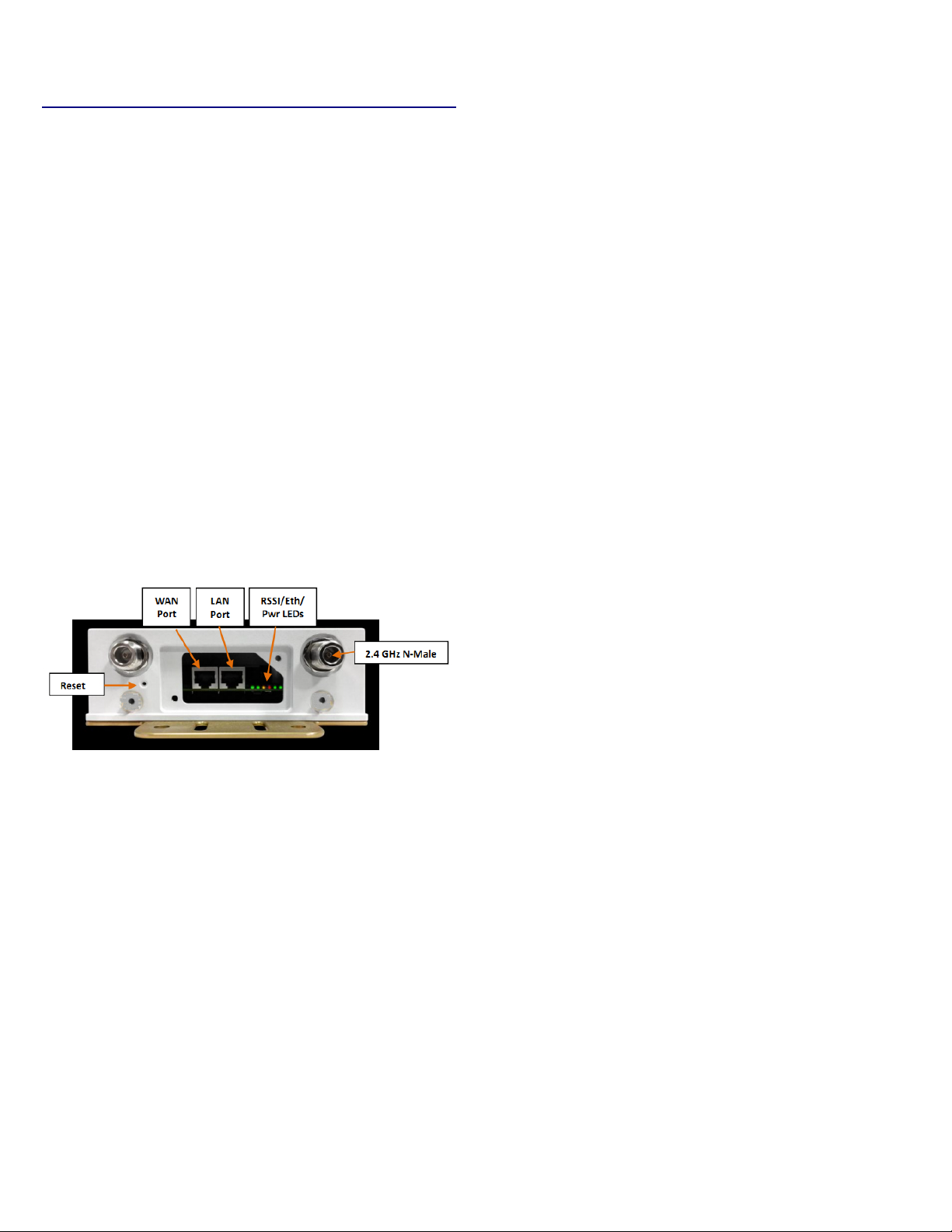
The Figure below shows the access panel of the unit
with the various user interfaces annotated for
reference.
Operating System: Microsoft Windows XP, Windows
Vista, Windows 7, Windows 8, Linux, or Mac OS X.
Web Browser: Mozilla Firefox, Google Chrome, Apple
Safari, or Microsoft Internet Explorer 8 or above.
1.5 Getting Started
Before establishing a link several parameters must be
configured using the web interface. To access the web
interface, perform the following steps:
1. Connect the local area network (LAN) port of
the radio to the PoE port of the PoE Injector
using a Cat5e Ethernet cable. Plug the PoE into
the AC power source. The rightmost LED on
the radio should illuminate, indicating the unit
is booting up.
2. Connect the network port of your computer to
the PoE injector network port using a Cat5e
Ethernet cable.
Figure 1 : Altum AC Interfaces and Indicators
1.2 Language
To change the language, please navigate to the
System page, look for the System Properties section,
click the Language and Style tab, and click the dropdown list for Language. You can change the language
from English to another language e.g. Chinese (中文).
1.3 Supported Products
This manual covers the following Altum AC models:
A600-EXT-US (External Connectors)
3. Assign the Ethernet adapter on your computer
with a static IP address on the 192.168.1.x
The first page that you see is the login page. The
words on the top left denote the Radio host name
and firmware build version e.g. A600 v1.51_b141027.
network, e.g. 192.168.1.10 and with a subnet
mask 255.255.255.0.
4. Launch a web browser and enter the default IP
address of the radio, 192.168.1.1, into the
address bar. The radio's configuration web
page should be presented.
6 LT-9064 Rev A Altum AC 600 User Manual
Page 7
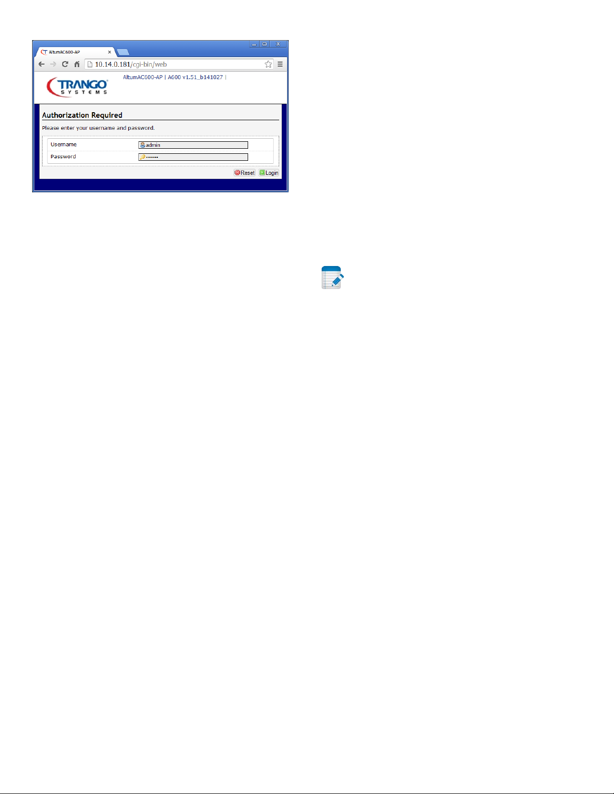
Figure 2: The login page is presented upon
requesting the radio's IP address.
The default credentials are:
Username: admin
Password: trango
1.7 Buttons and Changes
The buttons are described below.
Reset: Undo the changes.
Save: Saves the changes. Currently please do not use
this button.
Save & Apply: Saves and applies the changes. Please
use this button instead of the 'Save' button so that
the changes would be applied immediately. It is
recommended to click this button before moving to a
different page.
Logout: Logs out of the radio's web page.
1.6 Operating Modes
The radio can operate in the following modes:
1. Access Point / Master.
2. Station / Client.
3. Access Point WDS.
4. Station WDS.
A wide area network (WAN) is a network that covers a
broad area. The world's most popular WAN is the
Internet.
In a commonly used setup, the WAN port of an access
point connects to a modem via an Ethernet cable. A
modem can be a cable, digital subscriber line (DSL), or
fiber optic modem. A modem translates the signal
from the internet service provider (ISP) to Ethernet
signals that the access point can understand. This
allows the access point to have internet connection.
Note: At the top right corner of the radio's
configuration web page, there may be either of the
following texts displayed.
Changes: 0: Means that all changes on the
configuration web page have been applied to the
radio.
Unsaved Changes: Shows the number of changes that
have not yet been implemented in FLASH via the Save
& Apply button.
1.8 Physical Hardware Button
Please refer to Section 3.6.
1.9 LEDs
The light emitting diodes (LEDs) on the board are
described in Section 3.5 .
Other devices called stations connect wirelessly to
this access point. These devices can be other Altum
radios, mobile phones, printers, IP cameras, laptops.
The stations obtain internet connection from the
access point.
An access point WDS and a station WDS together
extend the wireless coverage, like a repeater. More
information on the setup can be found on page 28.
Altum AC 600 User Manual LT-9064 Rev A 7
Page 8
2.1.1 Wireless Radio Mode
Chapter 2: Status Tab
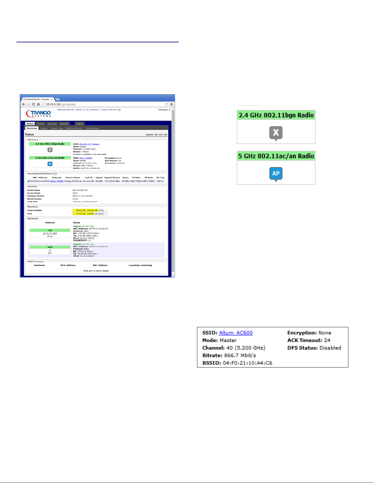
After login, when you click on the Status top-level tab,
you can see the second-level tabs of Overview, Routes,
System Log, Realtime Graphs. This is shown in Figure
2.
The wireless radio frequency band, supported modes,
and current mode are shown in the box on the left e.g.
“5 GHz 802.11ac/an Radio”. The mode can be AP or
CPE and is set based on the Wifi Configuration. For all
models the 5 GHz radio refers to SMA RP connectors.
The “2.4 GHz 802.11bgn Radio” refers to the N
connectors on the unit.
Figure 4: Wireless Radio Mode
Figure 3: The Status → Overview page.
Notice in the figure that the radio is using the latest
and fastest 11ac wireless standard that supports a
data rate of up to 866.7 Mbit/s over the air, which
translates to over 600 Mbps Layer 2 Ethernet capacity.
2.1 Overview
The Status → Overview page is divided into the
sections Wireless, Associated Stations, System,
Memory, Network, and DHCP Leases.
The word AP in the small callout box means that the
radio is operating in the Access Point (AP) mode. If
the callout is CPE, it means that the radio is operating
as customer-premises equipment (CPE) i.e. a station.
The Letter X is shown if the radio is disabled.
2.1.2 Wireless (for AP Mode)
The Wireless section in the Status → Overview page
shows a summary of the wireless parameters. The
following describes the parameters when the device
is in the AP mode.
Figure 5: A summary in the Wireless section for a
device operating as an 802.11ac access point.
Uptime: Displays the duration of time since the radio
was last rebooted.
SSID: Displays the name of the wireless network that
this access point (AP) is offering, the Service Set
Identifier (SSID).
8 LT-9064 Rev A Altum AC 600 User Manual
Page 9
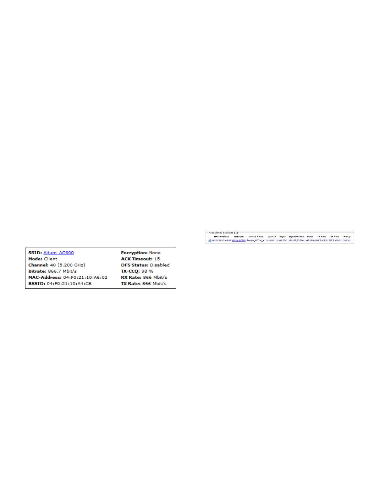
Mode: This is 'Master' if the device is in AP mode or
AP WDS mode.
Channel: Shows the channel number and frequency
that this AP is using.
Bitrate: This is the maximum bitrate supported by the
radio in the current configuration.
BSSID: This is the MAC address of the AP's radio. This
MAC should be used for PTP modes on the peer radio.
Encryption: Displays the wireless encryption used.
ACK Timeout: Shows the maximum acknowledgment
time in microseconds.
BSSID: This is the MAC address of the AP's radio.
Encryption: Displays the wireless encryption used.
ACK Timeout: Shows the maximum acknowledgment
time in microseconds.
DFS Status: If DFS is enabled, the AP automatically
switches channel if radar is detected on the current
channel.
TX-CCQ: Displays the transmission quality in %. A
higher percentage means a better wireless
connection quality.
RX Rate: Shows the receive bit rate of this station.
DFS Status: If DFS is enabled, the AP automatically
switches channel if radar is detected on the current
channel.
2.1.3 Wireless (for Station Mode)
The following describes the parameters for a device
operating in Station mode.
Figure 6: A summary in the Wireless section for a
device operating as an 802.11 station.
SSID: Displays the name of the wireless network that
this station should be associated with.
TX Rate: Shows the transmit bit rate of this station.
2.1.4 Associated Stations (for AP Mode)
This section shows the connected devices, if the radio
is in the AP mode.
Figure 7: List of Associated Stations.
If there are no associated stations, the text “No
information available” is displayed. The parameters
shown are as follows:
MAC-Address: Displays the MAC address of the
station's radio.
Network: States the name of the wireless network.
Mode: This is 'Client' if the device is in Station mode
or in Station WDS mode.
Channel: Shows the channel number and frequency
that this station is using. Normally, it would
automatically select the same channel as the AP.
Bitrate: This is the maximum bitrate supported by the
radio in the current configuration.
MAC-Address: States the MAC address of the device's
radio.
Altum AC 600 User Manual LT-9064 Rev A 9
Device Name: Shows the name of the station. (Does
not show for WDS mode)
Last IP: States the most recent IP address of the
station as seen by the AP (does not show for WDS
mode).
Signal: Displays the received signal strength from the
station e.g. -31 dBm.
Signal/Chains: Shows the received signal strengths
from the station on each antenna port e.g. -51, -52
Page 10
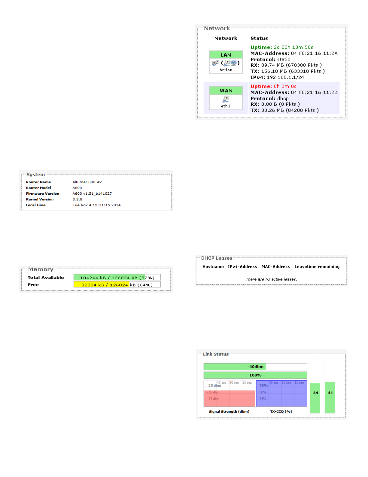
dBm. The value of 33 dBm is taken to mean “no
Figure 11: Currently active static DHCP leases.
Figure 10: Network summary.
Figure 9:
and
Memory.
antenna” if the radio has only 2 antennas.
Noise: Displays the received noise power at the AP.
TX Rate: Shows the transmit bit rate from the AP
towards this station.
RX Rate: Shows the receive bit rate at the AP from
this station.
TX-CCQ: Indicates the wireless connection quality.
2.1.5 System
This section shows the (Radio Unit) Name, Model,
Firmware Version, Kernel Version, and Local Time.
Figure 8: System parameters.
2.1.6 Memory
Here, the Total Available and Free memory are shown.
Total Available
Free
Status: Shows summaries of the interfaces for the
LAN and WAN zones. This may include uptime, MAC
address, protocol, bytes and packets received by the
device, bytes and packets transmitted by the device,
and its IPv4 address.
2.1.8 DHCP Leases
This section shows a table of MAC and IP addresses of
connected computers with static DHCP leases. They
are specified in the Network → Interfaces → LAN →
Static Leases section of the device's configuration
web page. More explanation is given in the Network
section of this user manual on page 23.
2.1.9 Link Status (for Station Mode)
2.1.7 Network
This section only applies if the device operates as an
This section displays the status of the LAN and WAN
networks.
10 LT-9064 Rev A Altum AC 600 User Manual
802.11 station.
Figure 12: The Link Status section.
Page 11
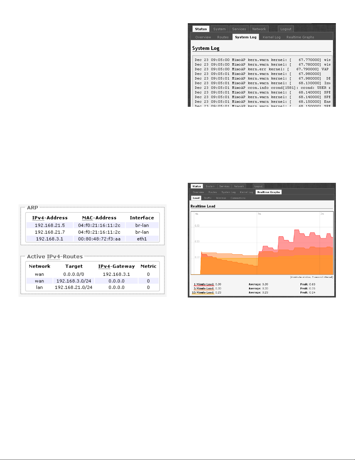
In the Link Status section on the Status → Overview
Figure 15: The graph for Realtime Load.
Figure 14: The
→
page.
Figure 13: The Status → Routes page.
web page, the value in the top left box denotes the
current received signal strength e.g. -40 dBm. The box
directly below it shows the current TX-CCQ
(transmission client connection quality) e.g. 100 %.
The bottom left box shows a realtime graph of the
received signal strength over the last 60 seconds. The
box directly to its right shows a realtime graph of the
TX-CCQ over the past 60 seconds.
On the right of this section, there are 2 vertical bars.
Each bar shows the current received signal strength of
each antenna e.g. -44 dBm, and -41 dBm. These
represent the H and V antenna polarizations for
streams 1 and 2.
2.2 Routes
When you click on the Status → Routes tab, you will
see the page that shows the routing rules that are
currently active on the device.
Status
System Log
2.4 Realtime Graphs
Under the tab for Realtime Graphs, there are four
tabs titled Load, Traffic, Wireless, and Connection.
2.4.1 Load
ARP: This address resolution protocol (ARP) table
shows the IP address and corresponding MAC address
of each device on the network.
Active IPv4-Routes: This table shows the IPv4
gateway and network ID (Target) for each subnet.
2.3 System Log
When you click on this tab, you can see the log of
system messages.
Altum AC 600 User Manual LT-9064 Rev A 11
Page 12
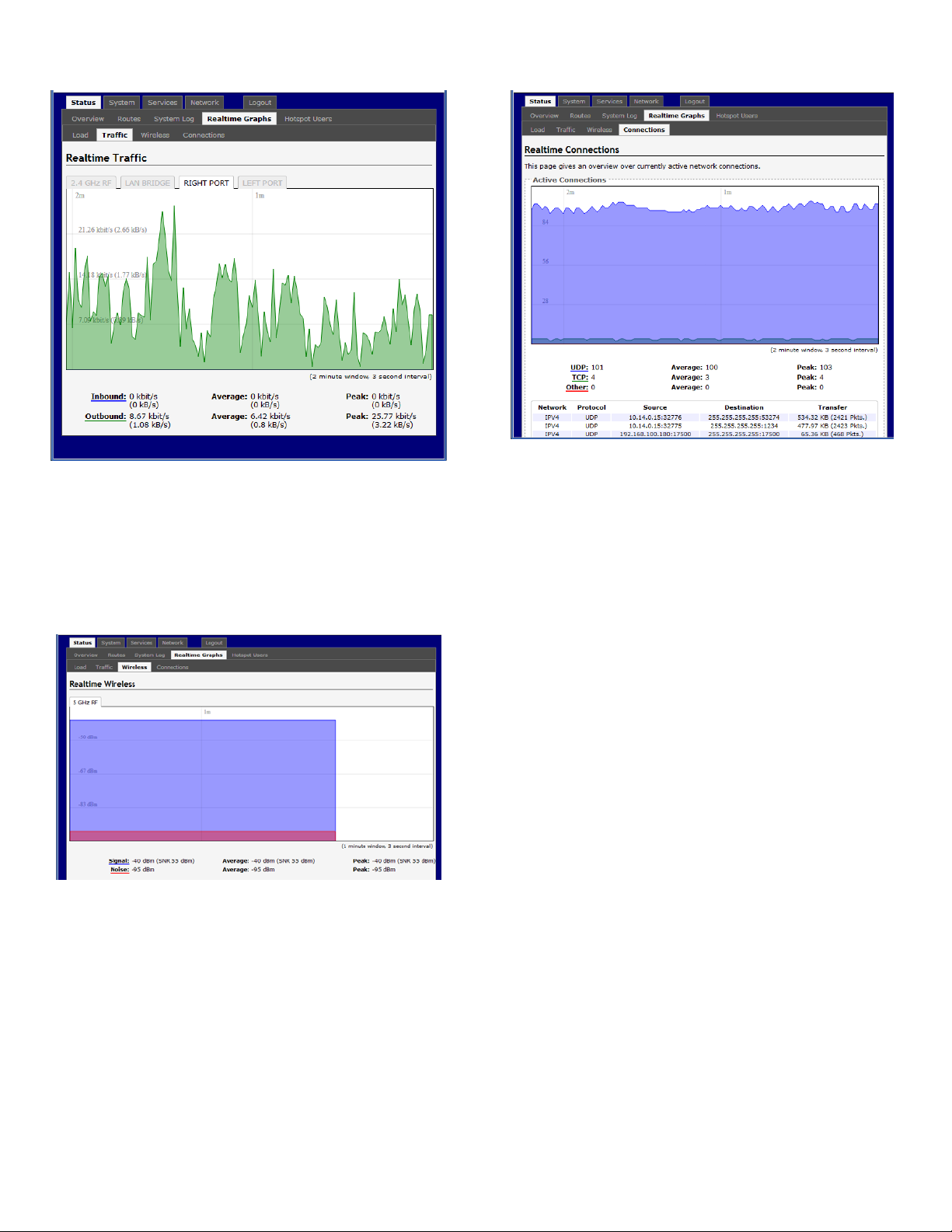
2.4.2 Traffic
Figure 16: The graph for Realtime Traffic.
2.4.4 Connections
Figure 18: The graph for Realtime Connections.
Note: that Right Port is the LAN port, and the Left
Port is the WAN Port.
2.4.3 Wireless
Figure 17: The graph for Realtime Wireless.
12 LT-9064 Rev A Altum AC 600 User Manual
Page 13
Chapter 3: System Tab
.
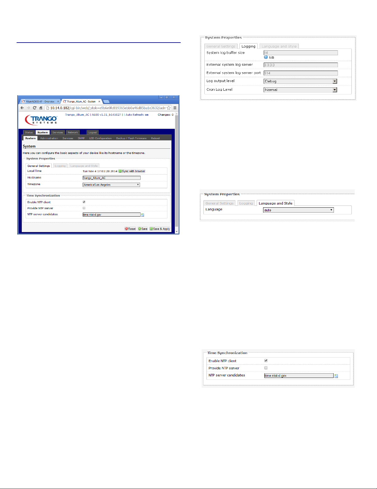
Figure 19: The System top-level tab.
This section is about the System top-level tab. Under
this tab, there is a row of tabs for Administration,
Services, SNMP, LED Configuration, Backup/Flash
Firmware, and Reboot. This can be seen in Figure 19.
Logging
Figure 20: Changing the system properties for
Logging
Logging: Specifies parameters used for the system log,
such as System log buffer size, External system log
server, External system log server port, Log output
level, and Cron Log Level.
Language
Within the System page, you can configure the device
parameters such as the hostname and timezone.
3.1.1 System Properties
Within the section on System Properties, there are
tabs corresponding to General Settings, Logging, and
Language and Style.
General Settings
Local Time: Displays the local time according to the
Timezone.
Hostname: Configures the name of the device.
Figure 21: Modifying the Language
Language and Style: Lets you choose the language of
the radio's web pages.
3.1.2 Time Synchronization
Enable NTP client: Obtains the date and time from
specified Network Time Protocol (NTP) servers.
NTP server candidates: These are the sources of the
time information. At least three are recommended for
accurate time synchronization.
Figure 22: Time Synchronization settings.
Timezone: Sets the timezone.
Altum AC 600 User Manual LT-9064 Rev A 13
Page 14
3.2 Administration
Figure 26: The radio's web server mode and port.
page.
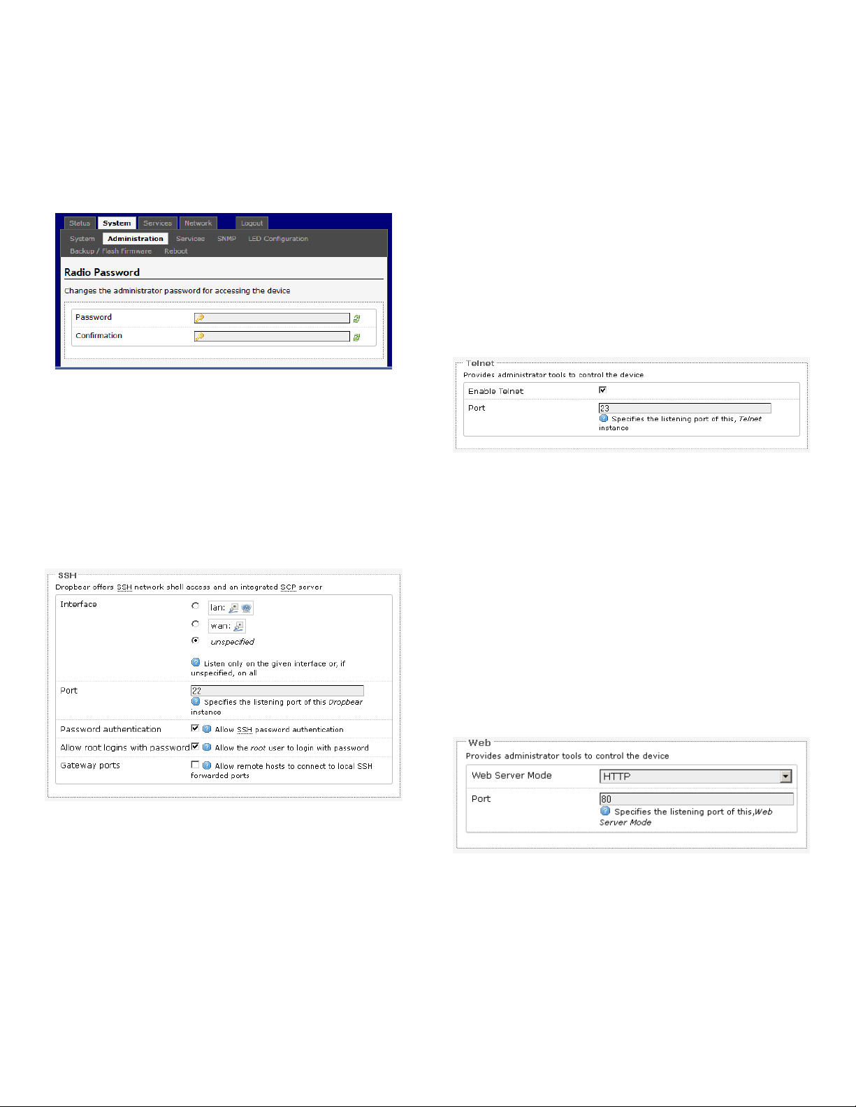
Within the System → Administration page, you can
configure the radio Password, SSH, Telnet , Web, and
FTP settings.
3.2.1 Password
Figure 23: Setting the radio password.
Password: Allows changing the password, the default
being trango.
Confirmation: Requires you to re-enter the password.
Interface: Lets the radio listen on a given interface or
all interfaces.
Port: Specifies the listening port, the default being 22.
Password authentication: Allows SSH password
authentication.
Allow root logins with password: This is enabled by
default.
Gateway ports: Allow remote hosts to connect to
local SSH forwarded ports.
3.2.3 Tel n et
Figure 25: Telnet settings in the System →
Administration page.
3.2.2 SSH
Figure 24: SSH settings in the System →
Administration
SSH: Allows access the radio's Linux shell and file
system using the Secure Shell protocol. For example,
the programs PuTTY and WinSCP can be used. It is
recommended to use the web interface for normal
setup and monitoring operations, and use SSH only
for debugging if needed.
Telnet: Provides administrator tools for controlling
the device or network debugging, over an
unencrypted connection. It is recommended to use
the web interface for normal setup and monitoring
operations, and use Telnet only for debugging if
needed.
Port: Specifies the listening port, the default being 23.
3.2.4 Web
Web Server Mode: This can be set to Hypertext
Transfer Protocol (HTTP) or Hypertext Transfer
Protocol Secure (HTTPS). For HTTPS, if you see the
warning, “The certificate is not trusted because it is
self-signed”. Click “Add Exception”, “Confirm Security
Exception” and proceed.
14 LT-9064 Rev A Altum AC 600 User Manual
Page 15
Port: Specifies the listening port, the default being 80
Services page.
for HTTP and 443 for HTTPS.
3.3 Services
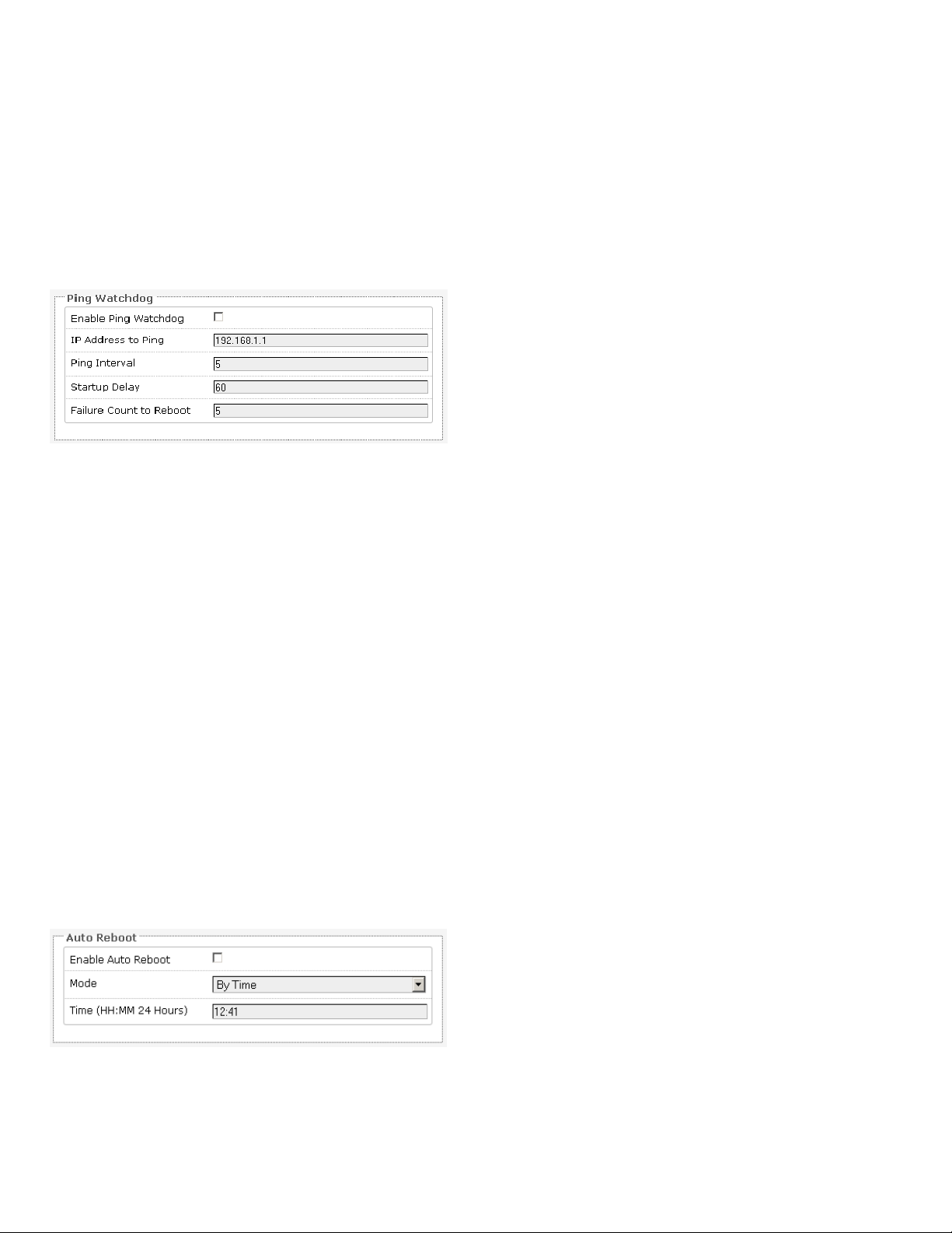
Auto Reboot: Allows the radio to reboot itself
automatically, disabled by default.
Mode: Chooses the Auto Reboot mode By T ime or By
Number of Hours.
In the System → Services page, you can configure the
Ping Watchdog and the Auto Reboot.
3.3.1 Ping Watchdog
Figure 27: Ping Watchdog settings in the System →
Ping Watchdog: Configures the device to ping to a
remote IP address and reboot if the connection is lost.
It is disabled by default.
IP Address to Ping: Sets the remote IP address to ping
e.g. 192.168.1.10 or 8.8.8.8.
Ping Interval: Specifies the time between successive
pings, the default being 5 seconds.
Startup Delay: Sets the time delay in seconds after
the radio finishes rebooting, before running the Ping
Watchdog, the default being 60 seconds.
Time: Sets the time of day to reboot if the Mode is By
Time.
Number of Hours: Sets the delay as an integer
number of hours after each reboot, if the Mode is By
Number of Hours.
3.4 SNMP
The Simple Network Management Protocol (SNMP) is
an Internet-standard protocol for managing devices
on IP networks. It consists of a set of standards for
network management, including an application layer
protocol, a database schema, and a set of data
objects. SNMP exposes management data in the form
of variables on the managed systems, which describe
the system configuration. These variables can then be
queried (and sometimes set) by managing
applications.
In the System → SNMP Page, you can configure SNMP
V2c and SNMP V3.
A MIB file with detailed information is available from
the Trango Website that can be loaded on the SNMP
Manager.
Failure Count to Reboot: Specifies the number of
3.4.1 SNMP Information
failed pings before the radio reboots automatically.
3.3.2 Auto Reboot
Figure 28: Auto Reboot settings in the System →
Services page.
Altum AC 600 User Manual LT-9064 Rev A 15
In the SNMP Information section, the text fields for
the SNMP Enterprise ID, Contact, and Location
information are shown.
Page 16
3.4.2 SNMP Configuration
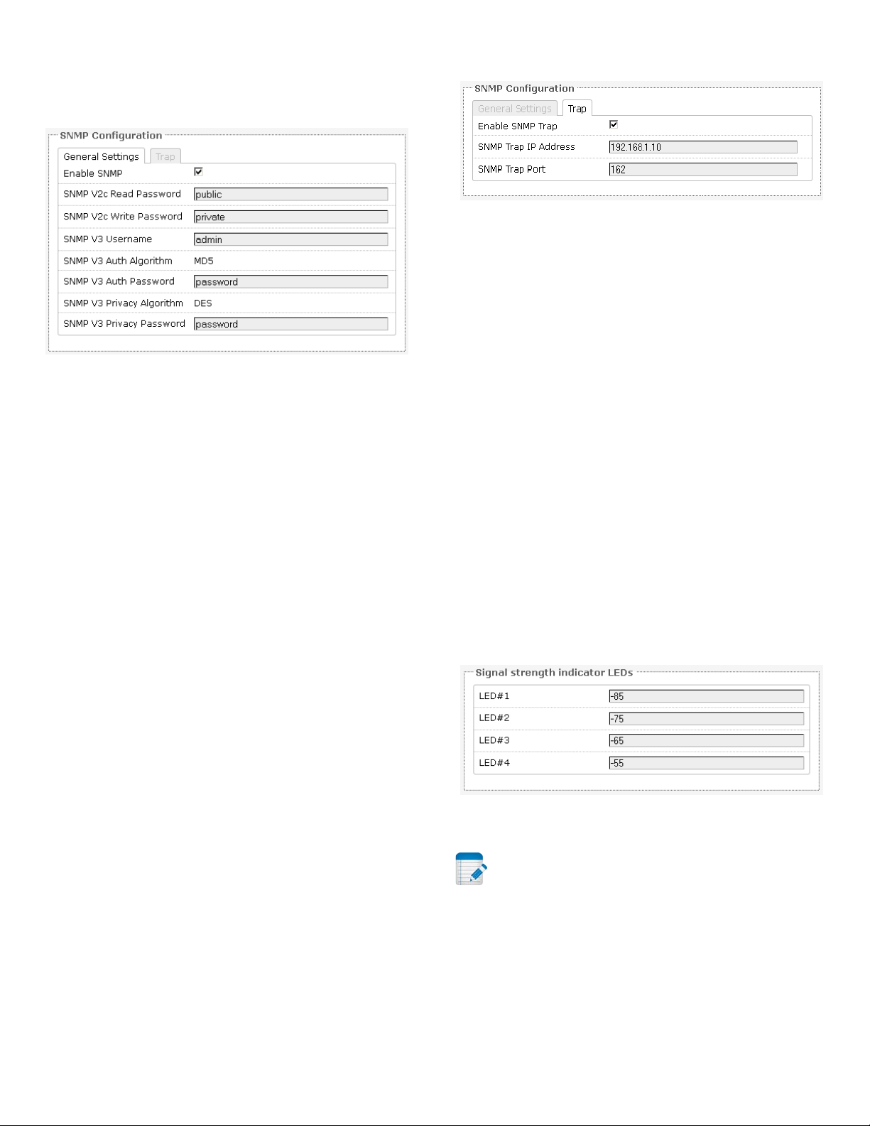
default threshold values in dBm.
General Settings
Trap
Figure 29: General settings for SNMP.
Enable SNMP: Enables SNMP.
SNMP V2c Read Password: Sets the community string
for read-only access (to the variables on the SNMP
agent) by the network management system (NMS).
The NMS is the software which runs on the SNMP
manager. (default: public)
SNMP V2c Write Password: Sets the community
string for read-write access by the SNMP manager.
(default: private)
A community string identifies a group of SNMP agents.
It is sent in clear text. It should be changed from the
default string “public” or “private”. The variables on
the SNMP agent can be classified into read-only or
read-write variables.
Figure 30: SNMP trap configuration.
Enable SNMP Trap: Allows the SNMP agent to notify
the SNMP manager of events.
SNMP Trap IP Address: Sets the IP address of the
SNMP manager which receives the trap messages.
SNMP Trap Port: Sets the port number.
3.5 LED Configuration
The System → LED Configuration page customizes the
behaviour of the LEDs.
Signal strength indicator interface: Chooses the
Wireless radio to use based on the wireless network
name.
Signal strength indicator LEDs: Sets the received
signal strength thresholds (in dBm) above which LEDs
#1 to #4 would light up.
SNMP V3 Username: Sets the username for
authentication. (default: admin)
Figure 31: Signal strength indicator LEDs and their
SNMP V3 Auth Algorithm: Shows the authentication
algorithm used e.g. MD5.
SNMP V3 Auth Password: Configures the password
for user authentication. (default: password)
SNMP V3 Privacy Algorithm: Shows the data
encryption algorithm used e.g. DES.
SNMP V3 Privacy Password: Sets the password for
data encryption. (default: password)
16 LT-9064 Rev A Altum AC 600 User Manual
Note: The physical arrangement of LEDs on the
radio is as follows starting from the furthest to the
right of the Access Port and moving left are: Power
(green), Diagnostics (green), LED#1 (red), LED#2
(orange), LED#3 (green), and LED#4 (green). LEDs 14 are used for RSSI typically.
Page 17

3.6 Physical Hardware Button
Duration of button press
Action
There is a physical button on the radio unit which is
located to the left of the access port through a tiny
hole. Use a paperclip to set the action desired.
Depending on how long the button is pressed, you
can reboot the board or reset it to factory default.
First make sure then power is on. The following table
shows the duration of the button press and the
corresponding action.
0 - 3 seconds reboot
4 - 30 seconds reset to factory default
more than 30 seconds do nothing
3.7 Backup/Flash Firmware
Firmware: Shows the current version of the firmware
and allows you to upload a new firmware.
3.8 Reboot
Perform reboot: Reboots the operating system of
your device. This is similar to the power-off and
power-on cycle. The system configuration remains the
same. Any changes that are not applied are lost.
The System → Backup/Flash Firmware page lets you
perform backup and restore, or flash a new firmware.
3.7.1 Backup/Restore
Download backup: Generate archive: Downloads a
tar archive of the current configuration files.
Note: The backup archive file should be stored
in a safe place because it contains the wireless
password in clear text.
Reset to defaults: Perform reset: Resets the firmware
to its initial state.
Restore backup: Upload archive: Lets you upload a
previously generated backup archive to restore
configuration files.
3.7.2 Flash new firmware
You can upload a new firmware to replace the
currently running firmware.
Keep settings: Retains the current configuration.
Altum AC 600 User Manual LT-9064 Rev A 17
Page 18
Chapter 4: Services Tab
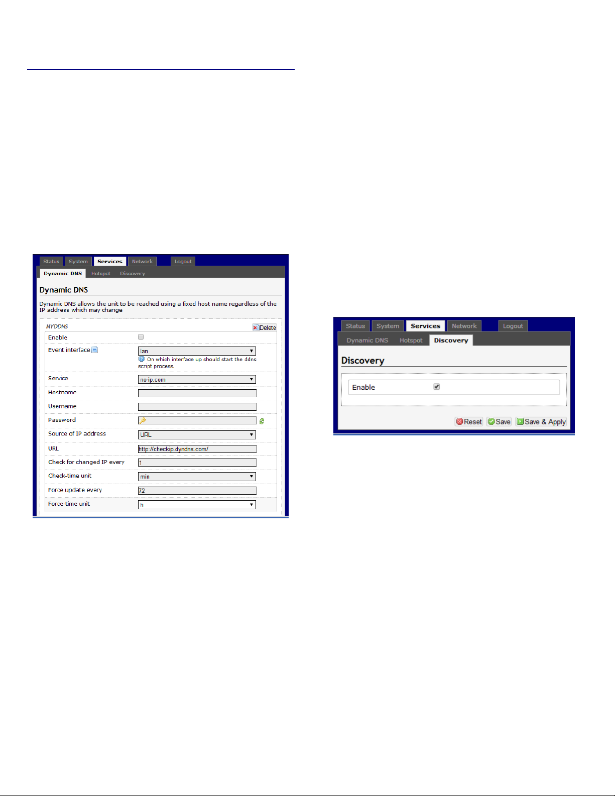
Figure 32: The Services → Dynamic DNS page.
The Services top-level tab contains the configuration
pages for Dynamic DNS and Discovery.
4.1 Dynamic DNS
The domain name system (DNS) translates a URL like
www.yahoo.com to an IP address like 206.190.36.45.
Dynamic DNS (DDNS) allows the with the public IP
address to be reached from the internet via a URL
even if its IP address is dynamically changing.
Username: Sets the username registered for the
DDNS service.
Password: Sets the password registered for the DDNS
service.
Source of IP Address: Configures the source of the IP
address information. The default is URL.
URL: Sets the URL of the source of the IP address
information e.g. http://checkip.dyndns.com/.
Check for changed IP every: The default is to check
the IP address every 1 minute.
Force update every: The default is to force update
every 72 hours.
4.2 Discovery
Enable: Enables the dynamic DNS.
Event interface: Chooses the interface, e.g. LAN or
WAN, for which “interface up” would run the DDNS
script process.
Service: Chooses the DDNS service provider e.g. no-
ip.com.
Hostname: Specifies the hostname e.g. y0033.no-
ip.biz.
Figure 33: The Services → Discovery page.
Enable: Allows the Device Name and Last IP address
of the wireless station to be discovered by the
wireless access point. The functionality is similar to
the Cisco Discovery Protocol. Discovery is enabled by
default.
18 LT-9064 Rev A Altum AC 600 User Manual
Page 19
Chapter 5: Network Tab
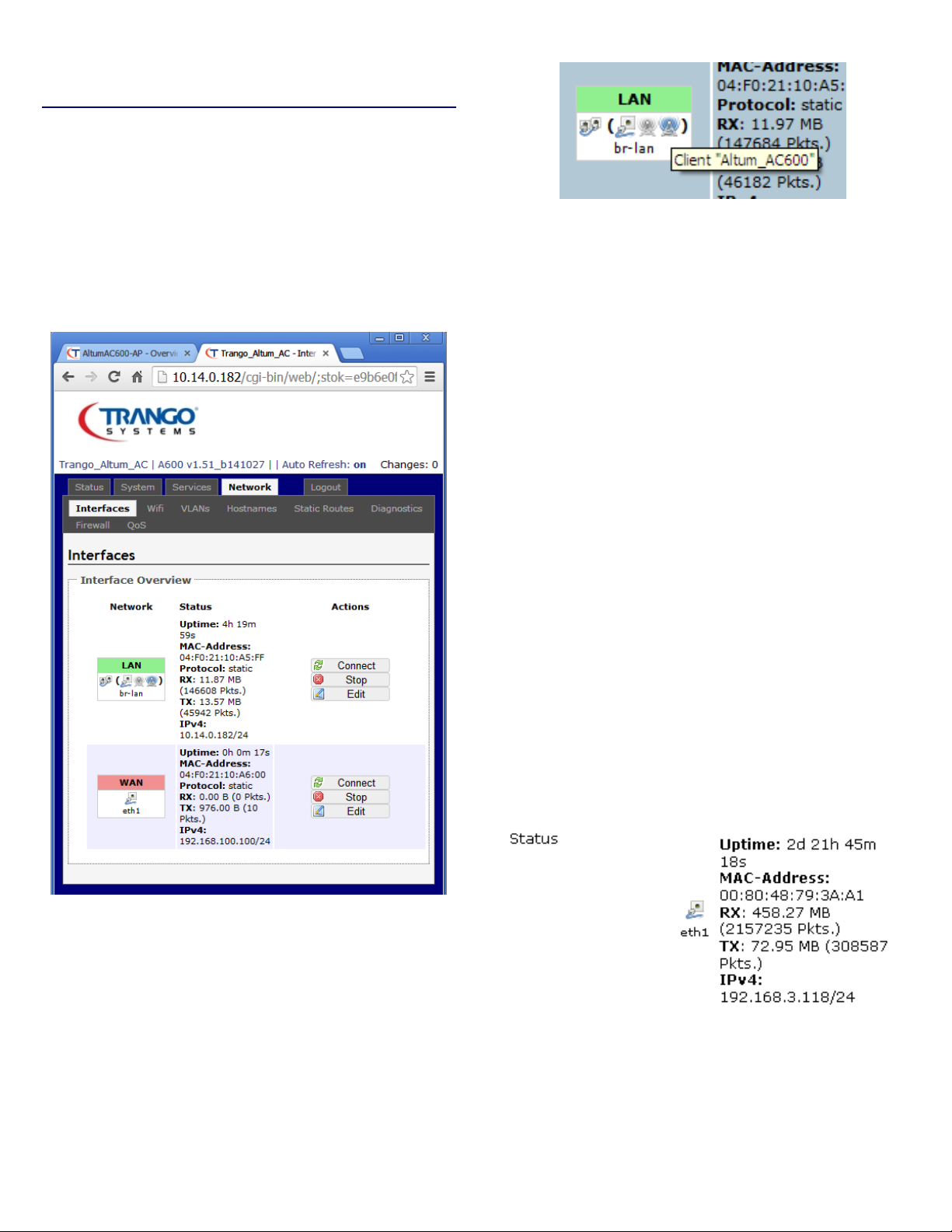
: Status of the “eth1” interface of the WAN
zone.
Figure 35: The Interface Overview on the Network
The Network → Interfaces tab shows an overview of
the network interfaces. You can view and configure
the interfaces of the local area network (LAN) zone as
well as the wide area network (WAN) zone. Network
address translation (NAT) occurs between these two
network zones. The radio that performs the NAT is
called a gateway. A gateway is a network point that
acts as an entrance to another network.
Figure 36: An infotip appears when
hovering the mouse over an icon.
In Figure 38, the LAN zone (icon with two Ethernet
ports) has the bridged interface “br-lan” which
consists of one physical port (icon with one Ethernet
port) and two wireless networks (tower icons) on the
device. Hovering the mouse over each icon would
give the name of the interface it represents. In this
example, the infotip shows that there is a (virtual)
client on the device with “Altum_AC600” as its
network name.
5.1 Interfaces – WAN
→ Interfaces page.
The Network column shows that the WAN zone has
the physical port “eth1” as its interface.
The Network → Interfaces → WAN page configures
the interface for the WAN zone.
5.1.1 Common Configuration
General Setup
Status: Shows a summary of the interface for the
WAN zone. This includes uptime, MAC address, bytes
and packets received by the device, bytes and packets
transmitted by the device, and its IPv4 address.
Figure 37
Protocol: Chooses between DHCP client (default),
where the device obtains it IP address automatically,
Altum AC 600 User Manual LT-9064 Rev A 19
Page 20

or Static address, where you can specify the device IP
address. Other protocols are PPTP, PPPoE, and L2TP.
VPN Server: Specifies the IP address of the remote
PPTP server for the virtual private network (VPN).
Protocol – Static address
IPv4 address: Sets the IP address of the device as
seen from the WAN zone.
IPv4 netmask: Sets the subnet mask e.g.
255.255.255.0. The IP address and netmask together
determine the subnet or network ID e.g.
192.168.3.0/24. Two devices must be in the same
subnet in order to establish a (Layer 2) link between
them.
IPv4 gateway: Specifies the IP address of the remote
server that allows the device's shell to gain internet
access.
IPv4 broadcast: Specifies the IPv4 broadcast address,
optional.
Use custom DNS servers: Configures the IP address of
the DNS servers e.g. 165.21.100.88 for the SingNet
DNS server in Singapore or 8.8.8.8 for the Google DNS
server in the USA. The computers in the same subnet
as this device can then set this device's IP address as
their preferred DNS server to obtain the same DNS
service.
PAP/CHAP username: Sets the username for the
Password Authentication Protocol (PAP) or the
Challenge-Handshake Authentication Protocol (CHAP).
PAP/CHAP password: Sets the password for the PAP
or CHAP.
Configure PPTP IP settings: Upon clicking the
“Configure...” button, the PPTP Common
Configuration page would be displayed. The protocol
DHCP client or Static address can be selected. The
corresponding options are explained within this
section (5.1.1 Common Configuration).
Protocol – PPPoE
The Point-to-Point Protocol over Ethernet (PPPoE) is a
network protocol for encapsulating PPP frames inside
Ethernet frames. Most DSL providers use PPPoE,
which provides authentication, encryption, and
compression.
The options PAP/CHAP username and PAP/CHA P
password have been explained earlier.
Access Concentrator: Identifies the PPPoE server.
Leave empty to autodetect.
Protocol – DHCP client
The Dynamic Host Configuration Protocol (DHCP) is a
standardized networking protocol used by servers on
an IP network to allocate IP addresses automatically
to client devices.
Hostname to send when requesting DHCP: Specifies
the name of this device as seen by the remote DHCP
server.
Protocol – PPTP
The Point-to-Point Tunneling Protocol (PPTP) is a
method for implementing virtual private networks.
PPTP uses a control channel over Transmission
Control Protocol (TCP) and a Generic Routing
Encapsulation (GRE) tunnel operating to encapsulate
Point-to-Point Protocol (PPP) packets.
Service Name: Specifies the PPPoE service name. The
server will accept clients which send an initialization
message with the service name that matches the
server's configuration. Leave empty to autodetect.
Protocol – L2TP
The Layer 2 Tunneling Protocol (L2TP) is a tunneling
protocol used to support virtual private networks
(VPNs) or as part of the delivery of services by ISPs. It
does not provide any encryption or confidentiality by
itself. Rather, it relies on an encryption protocol that it
passes within the tunnel to provide privacy.
The options PAP/CHAP username and PAP/CHA P
password have been explained earlier.
20 LT-9064 Rev A Altum AC 600 User Manual
Page 21

L2TP Server: Specifies the IP address of the remote
L2TP server.
Configure L2TP IP settings: Upon clicking the
“Configure...” button, the L2TP Common
Configuration page would be displayed. The protocol
DHCP client or Static address can be selected. The
corresponding options are explained within this
section (5.1.1 Common Configuration).
Vendor Class to send when requesting DHCP:
Identifies the vendor of a DHCP client for the
enhancement of vendor-specific DHCP functionality.
The following three options are specific to the PPTP
and PPPoE protocols:
LCP echo failure threshold: Sets the number of link
control protocol (LCP) echo failures before the peer is
presumed to be dead. Use 0 to ignore failures.
Advanced Settings
The following are options in the Advanced Settings
section tab. Some of these options are shown,
depending on the protocol being used.
Override MAC address: Allows you to specify a
different MAC address other than the radio's original
MAC address. This is useful if the ISP uses the MAC
address of a radio to identify a customer. Suppose
that the radio needs to be replaced. The new radio
can take on the MAC address of the previous radio in
order to continue having internet access.
Override MTU: Sets the maximum transmission unit
(MTU), the default being 1500 bytes. Unless, your ISP
requires, it is not recommended to change this setting.
Use gateway metric: Allows you to specify a gateway
metric. This acts as a cost for choosing the gateway
when a connected device has to select between
multiple available gateways. The gateway with the
smallest metric is chosen.
Use broadcast flag: When sending DHCP requests, a
client can indicate if it wants an answer in unicast or
broadcast, by setting the broadcast flag. This is
required for certain ISPs. Unchecked by default.
LCP echo interval: Specifies the interval in seconds to
send LCP echo requests. This is only effective in
conjunction with failure threshold.
Inactivity timeout: Sets the number of seconds of
inactivity, after which the connection is closed. Use 0
to persist connection.
Physical Settings
Interface: Chooses which physical interface to use for
the WAN zone. This can be the Ethernet Adapter
“eth0” or “eth1” that corresponds to each of the two
ports on the device for example. It could also be set
as the Wireless Network. If No Interface is selected, all
interfaces would be within the LAN zone.
Note: For boards with 2 ethernet ports, both
ports would be LAN ports in the default configuration.
You can still designate the WAN port in the firmware.
For s with power over Ethernet (PoE), only the port
further away from the DC Jack (right port) would be
the PoE input port (ethY). The port nearer to the DC
Jack (left port) would be the PoE output port (ethX).
Use default gateway: Configures a default route.
5.2 Interfaces – LAN
Checked by default.
5.2.1 Common Configuration
Use DNS servers advertised by peer: Uses the DNS
settings advertised by the DHCP server. Checked by
default.
Client ID to send when requesting DHCP: Sets the
identifier that may be required by the ISP or network
administrator. If not stated, the MAC address of the
client will be sent.
Altum AC 600 User Manual LT-9064 Rev A 21
General Setup
Status: Shows a summary of the current LAN port
status, which includes uptime, MAC address, received
bytes and packets, transmitted bytes and packets, and
IPv4 address.
Page 22

Protocol – DHCP client
lan” interface of the LAN
zone.
The Dynamic Host Configuration Protocol (DHCP) is a
standardized networking protocol used by servers on
an IP network to allocate IP addresses automatically
to client devices.
Hostname to send when requesting DHCP: Specifies
the name of this device as seen by the remote DHCP
server.
Figure 38: Status of the “br-
Protocol: Chooses between Static address, where you
can specify the device IP address, or DHCP client,
where the device obtains it IP address automatically.
Static address is necessary if other devices obtain
internet connection through this device. Static
address is also recommended if you wish to configure
the device via the web interface.
Protocol – Static address
IPv4 address: Sets the IP address of the device e.g.
192.168.21.1, where you can access the radio's
configuration web page.
IPv4 netmask: Sets the subnet mask e.g.
255.255.255.0. The IP address and netmask together
determine the subnet or network ID e.g.
192.168.21.0/24. Two devices must be in the same
subnet in order to establish a (Layer 2) link between
them.
IPv4 gateway: Specifies the IP address of the remote
server that allows the device's shell to gain internet
access.
IPv4 broadcast: Specifies the IPv4 broadcast address,
optional.
Advanced Settings
The following are options in the Advanced Settings
section tab. Some of these options are shown,
depending on the protocol being used.
Override MAC address: Allows you to specify a
different MAC address other than the radio's original
MAC address. This is useful if the ISP uses the MAC
address of a radio to identify a customer. Suppose
that the radio needs to be replaced. The new radio
can take on the MAC address of the previous radio in
order to continue having internet access.
Override MTU: Sets the maximum transmission unit
(MTU), the default being 1500 bytes. Unless, your ISP
requires, it is not recommended to change this setting.
Use gateway metric: Allows you to specify a gateway
metric. This acts as a cost for choosing the gateway
when a connected device has to select between
multiple available gateways. The gateway with the
smallest metric is chosen.
Use broadcast flag: When sending DHCP requests, a
client can indicate if it wants an answer in unicast or
broadcast, by setting the broadcast flag. This is
required for certain ISPs. Unchecked by default.
Use custom DNS servers: Configures the IP address of
the DNS servers e.g. 165.21.100.88 for the SingNet
DNS server in Singapore or 8.8.8.8 for the Google DNS
server in the USA. The computers in the same subnet
as this device can then set this device's IP address as
their preferred DNS server to obtain the same DNS
service.
22 LT-9064 Rev A Altum AC 600 User Manual
Use default gateway: Configures a default route.
Checked by default.
Use DNS servers advertised by peer: Uses the DNS
settings advertised by the DHCP server. Checked by
default.
Client ID to send when requesting DHCP: Sets the
identifier that may be required by the ISP or network
Page 23
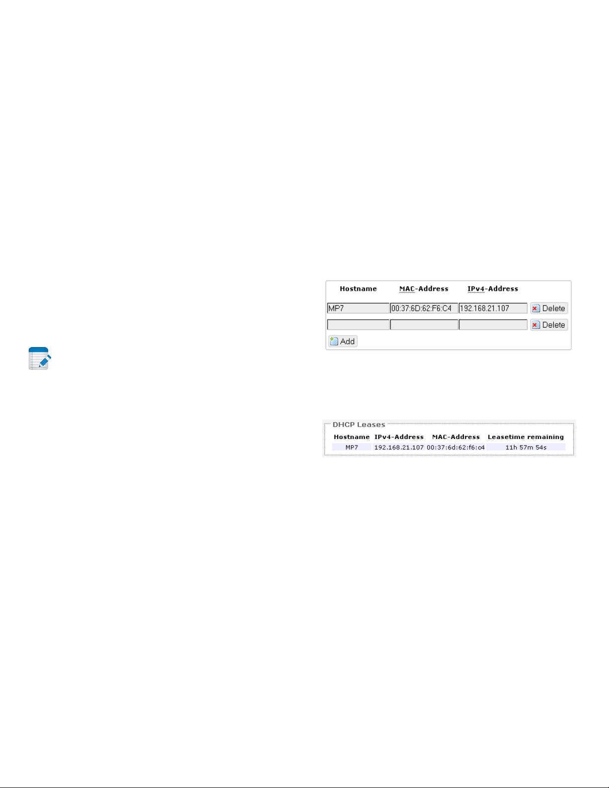
administrator. If not stated, the MAC address of the
Figure 39: Adding a static DHCP lease.
client will be sent.
Vendor Class to send when requesting DHCP:
Identifies the vendor of a DHCP client for the
enhancement of vendor-specific DHCP functionality.
Physical Settings
DHCP-Options: Defines additional DHCP options, for
example "6,192.168.2.1,192.168.2.2" which
advertises different DNS servers to clients. Normally,
connected devices would take this board's IP address
as the default gateway. To set an alternative default
gateway, add the DHCP option "3,192.168.2.3" for
example. More information can be found in this link:
http://wiki.openwrt.org/doc/uci/dhcp.
Enable STP: Enables the Spanning Tree Protocol on
this bridge. It is unchecked by default.
5.2.2 DHCP Server
This section allows you to configure the device as a
DHCP server.
General Setup
Ignore interface: Disables DHCP for this interface. You
should uncheck this to enable DHCP.
Note: All the following options in this DHCP
Server section depend on DHCP being enabled.
Start: Specifies the lowest leased address as offset
from the network address, the default being 100.
Limit: Sets the maximum number of leased addresses,
the default being 150.
Leasetime: States the expiry time of leased addresses,
the default being 12h.
5.2.3 Static Leases
In this section, you can specify that a particular DHCP
client obtain an IP address that you define. The MAC
address of the client is required. Click the Add button
to add a static DHCP lease, then click Save & Apply to
apply the changes.
The static DHCP lease shows up on the Status →
Overview page if the client is active.
Figure 40: The static DHCP leases on the Status →
Overview page.
5.3 Wifi – Overview
Advanced Settings
Clicking on the Network → Wifi tab would bring you
Dynamic DHCP: Dynamically allocates DHCP
addresses for clients. If disabled, only clients having
static leases will be served. Checked by default.
Force: Forces DHCP on this network even if another
server is detected, unchecked by default.
IPv4-Netmask: Overrides the netmask sent to clients.
Normally it is calculated from the subnet that is
served.
Altum AC 600 User Manual LT-9064 Rev A 23
to the Wireless Overview page. This page shows the
radios present on the device. These may include the
on-board radio and the miniPCI/miniPCIe radio card.
The wireless local area networks (WLANs) are
displayed under each radio.
Page 24
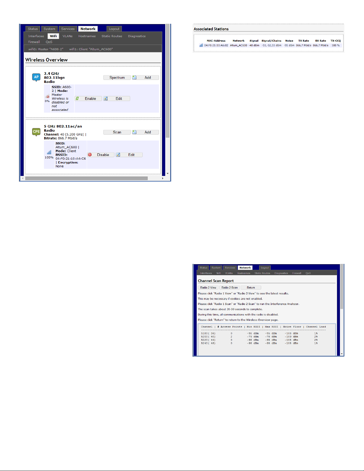
Figure 41: The Wireless Overview page showing two
radios.
In Figure 43, two tabs are shown at the top, wifi0:
Master “A600-2” and wifi1: Client “Altum_AC600”.
These correspond to the two radios in the window
below.
Figure 42: The Associated Stations are also shown
on the Wireless Overview page.
The MAC address, network name, received signal
strength, noise power, transmit rate, receive rate, and
transmission quality for each station are displayed.
5.3.2 Spectrum: Interference Analyzer for
AP
For a radio in AP mode, clicking the Spectrum button
would bring up the Channel Scan Report page. Only
the radios that are enabled will be available for
scanning, and only the frequency band currently in
use will be scanned for each enabled radio (2.4-2.48,
5.15-5.25, 5.725-5.85, etc.)
Press the Radio 2 Scan button to look at the spectrum
for the 5 GHz Radio and Radio 1 Scan for 2.4 GHz.
You can click 'Radio 1 Scan' to do the full channel scan
again and get the latest results.
The buttons are explained as follows.
Spectrum: Shows the Channel Scan Report and allows
you to run the Interference Analyzer.
Add: Allows you to add virtual access points (VAPs) to
the radio. By default, there is only one VAP on the
radio. Each VAP corresponds to one network.
Enable: Enables the radio.
Disable: Disables the radio.
Edit: Brings you to the configuration page of the
network. Clicking this button is equivalent to clicking
the corresponding tab above
5.3.1 Radio in AP Mode
When a radio is operating as an AP, the section for
Associated Stations shows a list of stations connected
to this device.
Figure 43: The Channel Scan Report.
The results show the RF Channel and number of
neighbouring access points (not including the Altum
AC) along with the Min RSSI, Max RSSI, Noise Floor,
and Channel Load.
24 LT-9064 Rev A Altum AC 600 User Manual
Page 25
Min RSSI: Shows the minimum received signal
strength indicator due to the neighbouring access
points.
Max RSSI: Shows the maximum received signal
strength indicator due to the neighbouring access
points.
Noise Floor: Shows the level of the noise on the
channel.
Channel Load: Shows how much the channel is
utilized. A lower channel load denotes a channel with
less interference.
Return: Brings you back to the Wireless Overview
page.
5.4 Wifi – Wireless Network
As mentioned earlier, clicking on the Edit button for a
network would bring up the configuration page. This
page contains the sections Device Configuration and
Interface Configuration.
The Device Configuration section covers the physical
settings of the radio hardware such as Country Code,
Wireles Profile, channel width, operating channel and
transmit power. These are shared among all defined
wireless networks of the radio. Per network settings
like encryption or operation mode are grouped in the
Interface Configuration.
5.4.1 Device Configuration
5.3.3 Radio in Station Mode
A radio can operate as a Station. This can be set in the
Interface Configuration → General Setup → Mode
option, after clicking on the Edit button.
Figure 44: The Wireless Overview page showing a
radio as a Client (station).
The following buttons are for a radio operating as a
station.
The Device Configuration section consists of the
section tabs for General Setup and Advanced Settings.
General Setup
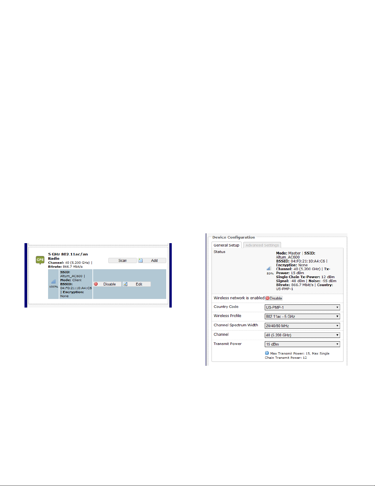
Status: Shows a summary of the wireless network.
Scan: Scans for available wireless networks. This
button is available if the device is operating as a
Station. You can then select the network to connect
to.
Join Network: Associates this device with the selected
wireless network.
Altum AC 600 User Manual LT-9064 Rev A 25
Figure 45: The Wifi Device Configuration section.
Enable: Enables the wireless network.
Disable: Disables the wireless network.
Country Code: Selects the country. Each country has
its own transmit power and frequency regulations. To
ensure regulatory compliance, you must select the
Page 26

country where the device is operating in. The transmit
power levels for each channel are tuned accordingly.
may also be manually selected. An AP and its station
must have the same channel in order to communicate.
The country codes should match for all radios on the
network.
For US, models there are sub categories which are
explained below:
US-PTP-1 – Point to Point Mode 5.15-5.25 GHz
US-PTP-2– Point to Point Mode 5.725-5.85 GHz
NOTE: When PTP modes are selected, a box will
appear in the Interface Configuration Section labelled
PTP-MAC which the user should enter the other end
of the links MAC address (BSSID for AP). This should
be done on both ends of the link to prevent any other
radios from linking to the PTP link. The Mode must
be set to Access Point (WDS) at one end and Station
(WDS) at the other end for this feature to work.
Wireless Profile: Chooses the wireless standard used.
802.11a and 802.11g are older standards while
802.11n is a newer standard that offers higher data
rates. The choice of 802.11g+n is a combination of
802.11g and 802.11n, and operates in the 2.4 GHz
frequency band. The choice of 802.11a+n is a
combination of 802.11a and 802.11n, and operates in
the 5 GHz frequency band. The 802.11ac is the latest
standard that offers even higher data rates (up to 866
Mbps OTA) and it also operates in the 5 GHz
frequency bands
Channel Spectrum Width: Selects whether 20 MHz or
20/40 MHz bands are used. A 40 MHz band has twice
the throughput of a 20 MHz band. A smaller
bandwidth may allow more devices to be connected.
The 20/40 MHz option allows both 20 and 40 MHz
bands to be used. When the 802.11ac wireless
standard is used, the 20/40/80 MHz band can be
selected. An 80 MHz band can carry twice the amount
of data of a 40 MHz band.
Obey Regulatory Power: Obeys the power
regulations specified by each country. This would
satisfy the legally permitted maximum for the
equivalent isotropically radiated power (EIRP) limits of
the selected country, based on the specified Antenna
Gain (dBi). The result is that the maximum transmit
power may be less than the capability of the radio.
Once activated, a refresh of the webpage may be
needed to show the settings correctly.
Transmit Power: Chooses the transmit power of the
radio e.g. 4 dBm, 5 dBm, …, 22 dBm or Max. This is
the total power supplied to the antennas of the radio.
The maximum power also depends on the frequency
channel used.
Allowable Antenna Gain
Due to FCC restrictions the professional installer
must use antennas of similar type and gain not
exceeding the following limits.
Point to Point Operation:
5.15-5.25 GHz: Max Gain 25 dBi including cable
losses. Max EIRP of +40 dBm.
5.725-5.85 GHz: Max Gain 25 dBi including cable
losses. Maximum EIRP not limited.
2.4-2.48 GHz: Max Gain = 9 dBi including cable losses.
Channel: Chooses the frequency channel. The default
setting of Auto is may be used. For an AP, it would
select the channel with the least interference from
other APs. For a station, Auto will automatically select
the same channel as its AP. The frequency channel
26 LT-9064 Rev A Altum AC 600 User Manual
Page 27
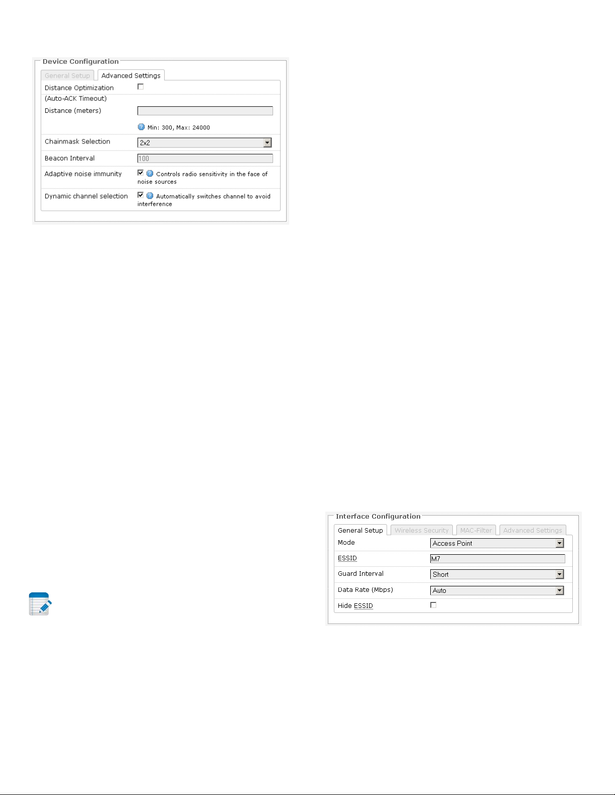
Advanced Settings
Figure 46: Advanced Settings for the Wifi Device
Configuration.
Distance Optimization (Auto-ACK Timeout):
Determines the distance of the connected station
from the AP and automatically adjusts the ACK
timeout. This is disabled(unchecked) by default. If the
stations are positioned over a wide area at different
distances from the AP (typically in PmP), it is
recommended to disable this option to prevent the
ACK timeout from fluctuating widely.
is 200 ms, a beacon will be transmitted from the radio
portion every 50 ms, from each VAP in a round-robin
fashion. The default value of the interval is 100 ms.
Adaptive noise immunity: Controls radio sensitivity in
the face of noise sources. Adaptive noise immunity
allows the AP to reject spurs and non-WLAN noise. An
advantage is that the AP would have to spend less
time decoding the signal, resulting in lower packet
loss rate.
Dynamic channel selection: Automatically switches
channel to avoid interference. Dynamic channel
selection is feature to detect and avoid continuous
wave (CW) interference. CW interference or spurs
cause the noise floor to be high. This stops
transmissions as well as causes a high dropped packet
rate. The noise floor is monitored by the calibration
logic. When the noise floor is above a threshold, the
AP is performs an automatic channel selection. It
would disconnect from the stations (it would already
have due to the interference) and move to a new
channel. The stations are expected to re-associate
with the AP on their own.
For Point to Point (PtP) links it is recommended to
check the box to optimize the timeout period
Distance (meters): Specifies the distance between the
AP and the station, if the previous option is
unchecked. Min: 300, Max: 12000 (80MHz), 24000
(40MHz), 48000 (20MHz). This value may be set to
slightly more than the physical distance between the
AP and the farthest station.
Chainmask Selection: Sets the antenna port selection
on the radio. For example, 2x2 means that 2 antennas
are being used for transmit and receive.
Note: The following options are for the device
operating as an access point (AP).
Beacon Interval: Specifies the interval between
beacon transmissions by the AP, in milliseconds. A
beacon is a frame broadcast by the AP to synchronize
the wireless network. For the multiple VAP case, the
beacons are transmitted evenly within this interval.
Thus, if four VAPs are created and the beacon interval
5.4.2 Interface Configuration
The Interface Configuration section contains the
section tabs for General Setup, Wireless Security,
MAC-Filter, and Advanced Settings.
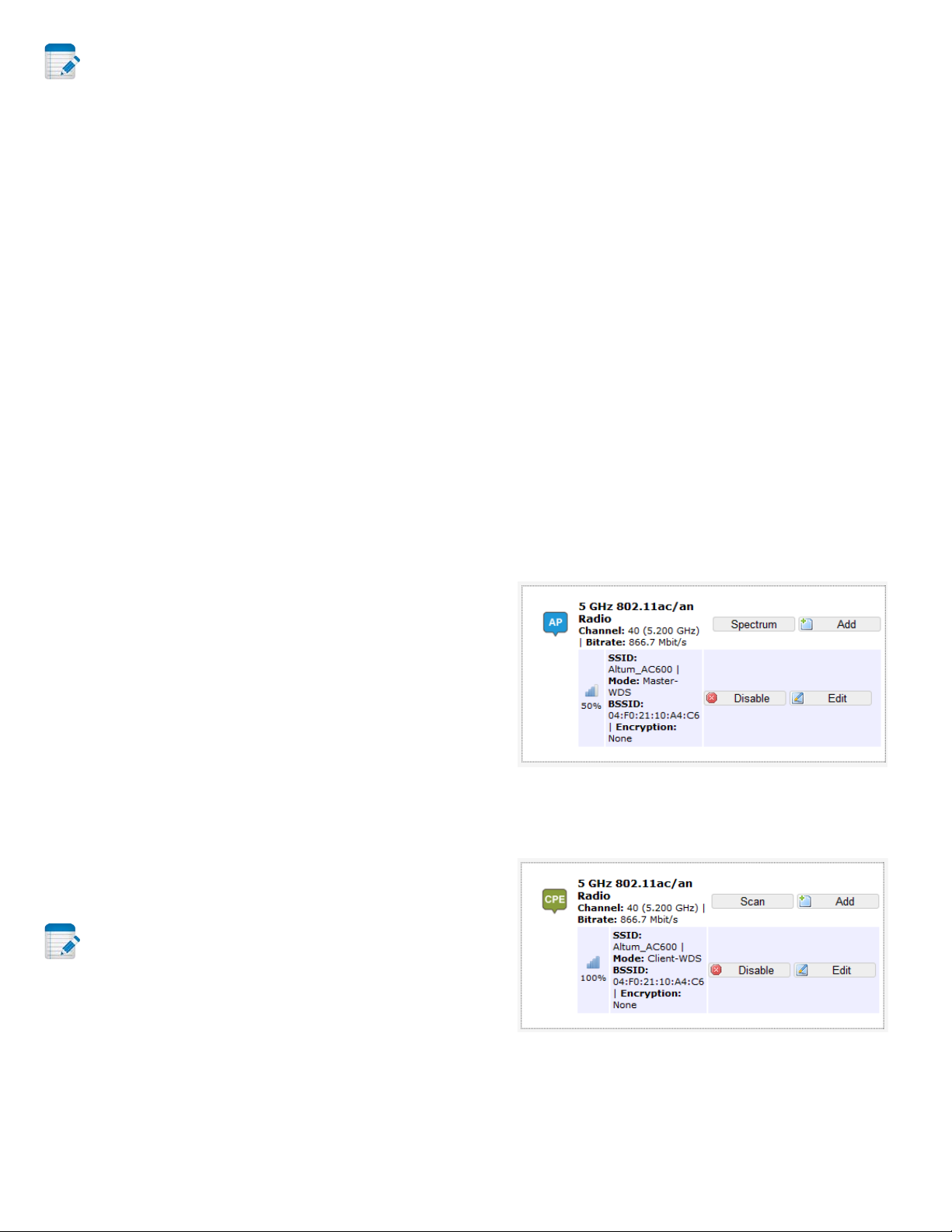
General Setup
Figure 47: The Wifi Interface Configuration section.
Mode: Selects whether the device is operating as an
Access Point (AP) or a Station. Other options are
Access Point WDS and Station WDS.
Altum AC 600 User Manual LT-9064 Rev A 27
Page 28
Note: Setting more than 1 station on a board is
not supported because there can only be one default
gateway. Both 2.4 and 5 GHz radios cannot be in
Station mode at the same time.
ESSID: Specifies the name or extended service set
identifier (ESSID) of the wireless network as it is
provided in the beacon message. The network name
can be up to 32 characters in length and can contain
spaces. When running in AP mode, it is the name of
the network as advertised in the beacon message. In
Station mode, it is the network name that the station
associates with.
in an IEEE 802.11 network. It allows a wireless
network to be expanded using access points without
the traditional requirement for a wired backbone to
link them. The notable advantage of WDS over other
solutions is it preserves the MAC addresses of client
frames across links between access points.
WDS may also be considered a repeater mode
because it appears to bridge and accept wireless
clients at the same time (unlike traditional bridging).
However, with this method, throughput is halved for
all clients connected wirelessly.
Setup for the WDS Modes
BSSID: Sets the MAC address of the AP. This option is
available for a device operating as a station. This is
useful because there can be multiple APs with the
same ESSID. Setting the MAC address would prevent
the station from roaming to other APs.
Guard Interval: Chooses between Short and Long
guard intervals. Guard intervals are used to ensure
that distinct transmissions do not interfere with one
another. Data rate is improved in downlink and uplink
if both AP and station use the Short Guard Interval.
Long Guard Intervals can improve performance in
high multipath environments with a small reduction
in maximum data rate.
Data Rate (Mbps): Selects the data rate or the
modulation and coding scheme (MCS). The default
setting of Auto is recommended for all profiles. The
MCS and data rates are adjusted automatically
depending on the wireless channel conditions.
Hide ESSID: Hides the network name (ESSID) from
being broadcast publicly. (This option is for a device
operating as an AP.)
The wireless distribution system (WDS) allows the
Station WDS to bridge wireless traffic transparently,
providing the functionality of a repeater. The Station
WDS is a transparent client and would need to
associate with an AP WDS. The WDS protocol is not
defined as a standard so there may be compatibility
issues between devices from different vendors. The
following figures show an example of a setup.
Figure 48: The first Radio is set to the AP WDS
mode.
Note: If the goal is securing your network, use
WPA or preferably WPA2-PSK encryption. Hiding the
ESSID does not provide complete security.
WDS
A Wireless Distribution System (WDS) is a system
enabling the wireless interconnection of access points
28 LT-9064 Rev A Altum AC 600 User Manual
Figure 49: The second Radio is set to the Station
WDS mode.
Page 29
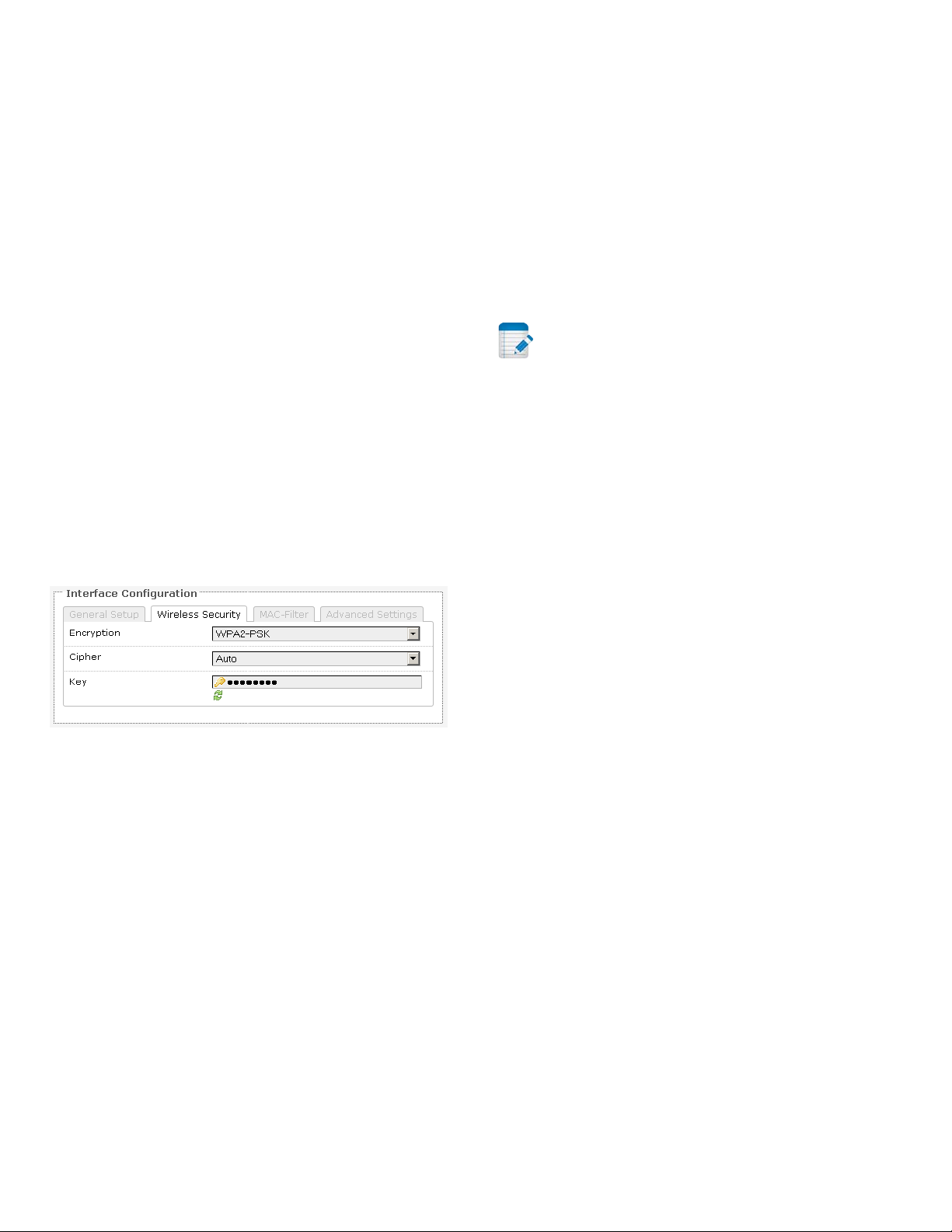
Multiple stations or Stations WDS can connect to an
AP WDS (unless the PTP Country code is used and the
PTP-MAC of the peer radio is entered) In Figure 52,
the Add button creates a virtual access point (VAP) on
the second . You should choose AP WDS mode for the
VAP's wireless network e.g. “M8” so that devices in
Station WDS mode can connect to this network. The
pair of Station WDS and AP WDS on the same board
extends the wireless coverage. If the board has two
radios, one onboard and one card radio, one radio can
be the Station WDS and the other radio can be the AP
WDS. Therefore the Station WDS with AP WDS on the
same board functions as a repeater.
In the non-WDS mode, the Station translates all the
packets that pass through it to its own MAC address,
thus resulting in a lack of transparency. A
consequence is that the ARP table of the access point
would show the MAC address of the Station assigned
to IP addresses of both the Station and the computer
connected to it.
would be used at a time. We have the following
options:
Used Key Slot: Chooses between Key #1 to Key #4.
Key #1: Specifies a string of characters to be used as
the password. It may consist of 5 ASCII characters or
10 HEX characters, implying a 64-bit WEP key length.
Otherwise, it may consist of 13 ASCII or 26 HEX
characters, implying a 128-bit key length.
Key #2, #3, and #4: Similar to Key #1.
Note: Valid HEX characters are numbers 0-9 and
letters A-F, case insensitive. Valid ASCII characters are
numbers and the letters of the English alphabet, case
sensitive. Based on the number of characters, the key
is automatically checked for validity. Invalid keys are
represented by red dots while valid keys are
represented by black dots. Click the green arrows icon
beside the text field to reveal/hide the password.
Wireless Security
Figure 50: Setting the Wireless Security for the Wifi
Interface.
Encryption: Chooses between No Encryption (open)
and the following encryptions: WEP Open System,
WEP Shared Key, WPA-PSK, WPA2-PSK, WPAPSK/WPA2-PSK Mixed Mode, WPA-EAP, and WPA2EAP.
WEP
Wired Equivalent Privacy (WEP) is the oldest and least
secure encryption algorithm. Stronger encryption
using WPA or WPA2 should be used where possible.
WPA or WPA2 with PSK
Wifi protected access (WPA) is a stronger encryption
than WEP.
Furthermore, WPA2 was developed to strengthen the
security of WPA and is stronger than WPA and WEP.
For WPA-PSK, WPA2-PSK, WPA-PSK/WPA2-PSK Mixed
Mode encryptions, we have the following options.
Cipher: Can be set to Auto, CCMP (AES), or TKIP and
CCMP (AES). The Temporal Key Integrity Protocol
(TKIP) was developed as a temporary replacement for
WEP. The Counter Mode Cipher Block Chaining
Message Authentication Code Protocol (CCMP) is
based on the Advanced Encryption Standard (AES)
and is the most secure protocol.
Key: The pre-shared key (PSK) is the password for the
wireless network. This may consist of 8 to 63 ASCII
characters.
For the WEP Open System and WEP Shared Key
encryptions, you can specify up to 4 keys and only 1
Altum AC 600 User Manual LT-9064 Rev A 29
WPA or WPA2 with EAP
The Extensible Authentication Protocol (EAP) is
encapsulated by the IEEE 802.1X authentication
Page 30
method. IEEE 802.1X is equivalent to EAP over LAN or
WLAN. Enterprise networks commonly use this
authentication method.
WPA or WPA2 with EAP (AP Mode)
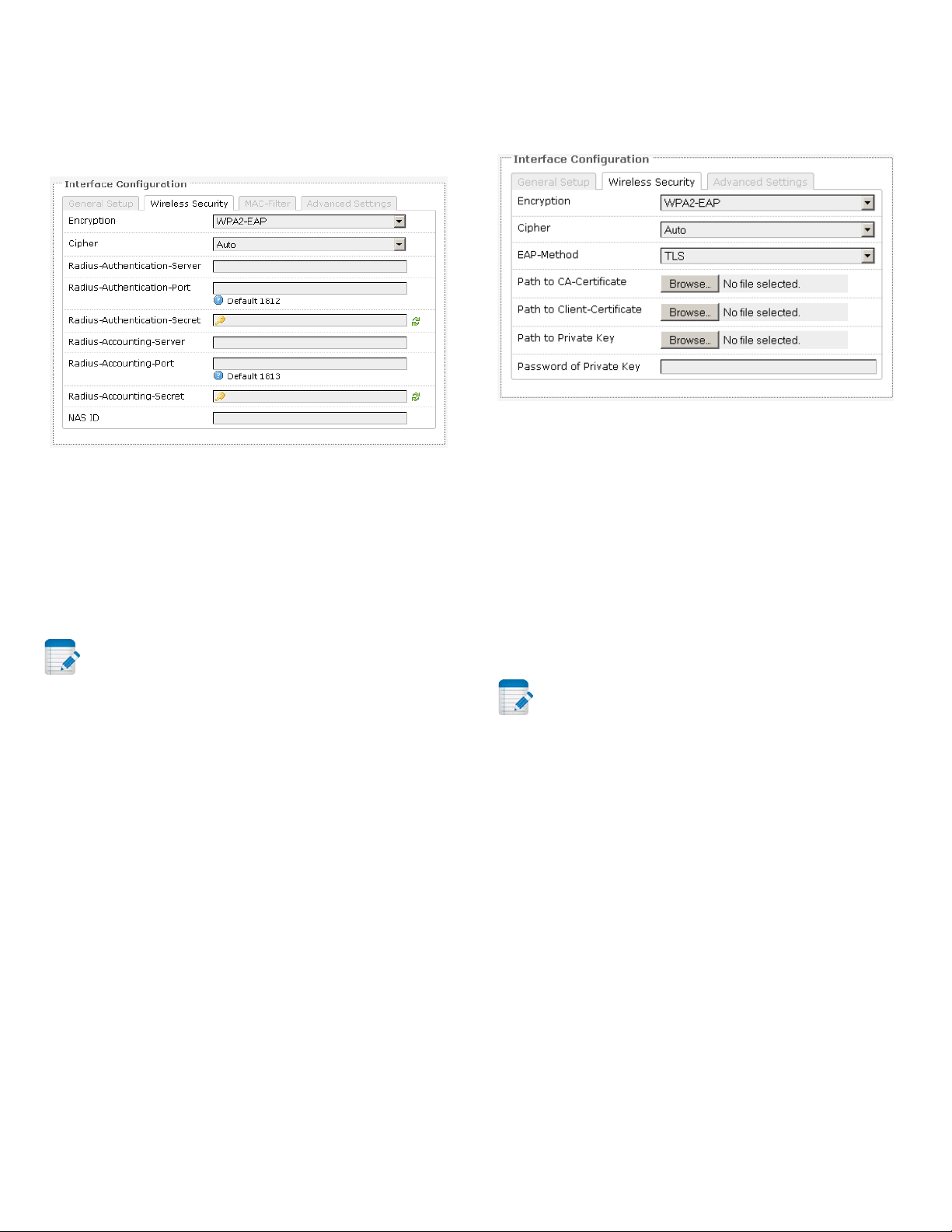
Figure 51: Encryption options for WPA-EAP or
WPA2-EAP in AP mode.
Cipher: Can be set to Auto, CCMP (AES), or TKIP and
CCMP (AES).
Radius-Authentication-Server: Specifies the IP
address of the RADIUS authentication server.
Note: Remote Authentication Dial In User
Service (RADIUS) is a networking protocol that
provides centralized Authentication, Authorization,
and Accounting (AAA) management for users that
connect and use a network service.
Radius-Authentication-Port: Sets the port number for
the RADIUS authentication server. Normally, the port
number is 1812.
Radius-Authentication-Secret: Configures the
password for the authentication transaction.
NAS ID: Specifies the identity of the network access
server (NAS).
WPA or WPA2 with EAP (Station Mode)
Figure 52: Encryption options for WPA-EAP or
WPA2-EAP in Station mode.
Cipher: Can be set to Auto, CCMP (AES), or TKIP and
CCMP (AES).
EAP-Method: The authentication protocol can be set
to Transport Layer Security (TLS), Tunneled TLS (TTLS),
or Protected EAP (PEAP).
Path to CA-Certificate: Selects the file for the CA
certificate.
Note: The certificate authority (CA) is a trusted
third party that issues digital certificates. In a public
key infrastructure scheme, a digital certificate certifies
the ownership of a public key by the named subject of
the certificate.
Path to Client-Certificate: Selects the file for the
client certificate.
Options for TLS as the EAP method
Radius-Accounting-Server: Specifies the IP address of
the RADIUS accounting server.
Radius-Accounting-Port: Sets the port number for the
RADIUS accounting server. Normally, the port number
is 1813.
Radius-Accounting-Secret: Configures the password
for the accounting transaction.
30 LT-9064 Rev A Altum AC 600 User Manual
Path to Private Key: Selects the file for the private key.
Password of Private Key: Configures the password for
the private key.
Page 31
Options for TTLS or PEAP as the EAP method
Authentication: Selects the authentication method
used by the AP, e.g. PAP, CHAP, MSCHAP, or
MSCHAPV2.
Identity: Sets the identity used by the supplicant for
EAP authentication.
Password: Sets the password used by the supplicant
for EAP authentication.
MAC-Filter
This section tab is only available for a device
operating as an AP.
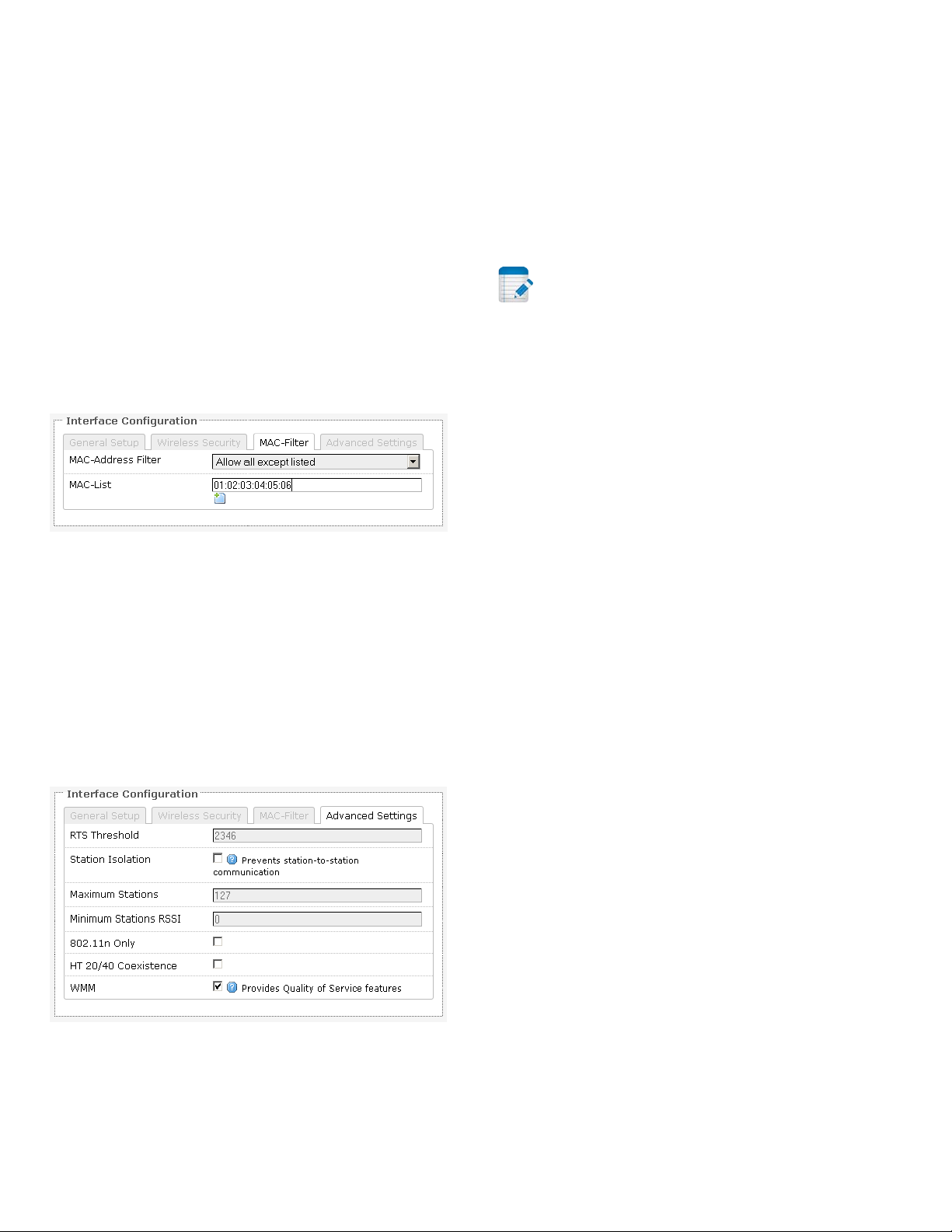
Figure 53: Configuring the MAC-Filter for a Wifi AP.
MAC-Address Filter: Lets you allow only devices with
the listed MAC address to associate with this AP, or
lets you block devices with the listed MAC address.
MAC-List: Adds the MAC address of the remote
device to either block or allow.
to consider when setting this parameter. On the one
hand, using a small value causes RTS packets to be
sent more often, consuming more of the available
bandwidth, and therefore reducing the throughput of
the network packet. On the other hand, when more
RTS packets are sent, the system recovers faster from
interference or collisions. This is useful in a heavily
loaded network, or a wireless network with high
electromagnetic interference.
Note: The following options for Station Isolation,
Maximum Stations, Minimum Stations RSSI, and
802.11n Only are available only for a device operating
as an AP.
Station Isolation: Prevents station-to-station
communication, unchecked by default. When Station
Isolation is disabled, wireless clients can communicate
with one another normally by sending traffic through
the AP. When Station Isolation is enabled, the AP
blocks communication between wireless clients on
the same AP.
Maximum Stations: Specifies the maximum number
of associated stations, the default being 127.
Minimum Stations RSSI: Sets the minimum received
signal strength indicator for a station to be associated.
The default value of 0 means that the AP would allow
a station to associate independent of its RSSI.
Advanced Settings
Figure 54: Advanced Settings for the Wifi Interface.
RTS Threshold: Sets the threshold for the packet size
above which the request to send (RTS) mechanism is
used. The default is 2346 octets. There is a trade-off
Altum AC 600 User Manual LT-9064 Rev A 31
802.11n Only: Forces the device to use only the
IEEE802.11n standard, unchecked by default.
WMM: Provides Quality of Service (QoS) features,
checked by default. Wireless multimedia enables the
classification of the network traffic into 4 main types,
voice, video, best effort, and background, in
decreasing order of priority. Higher priority traffic has
a higher transmission opportunity and would have to
wait less time to transmit. As a result, an existing
video stream would not be interrupted by additional
background processes.
Page 32
5.5 VLANs
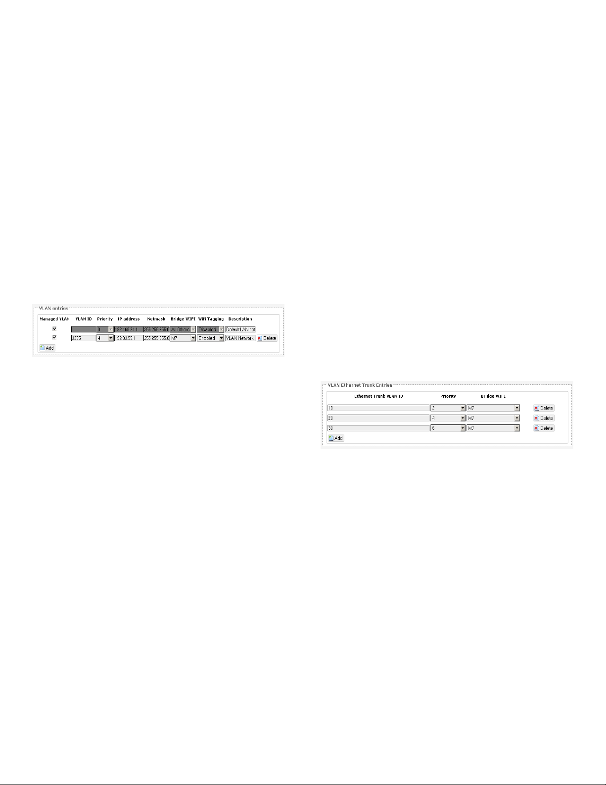
A local area network (LAN) can be divided into
multiple distinct virtual LANs (VLANs) with the use of
VLAN switches. This improves the management and
security of the network. The broadcast domain of a
device on a VLAN is confined to all devices on the
same VLAN.
The Network → VLAN page contains the sections for
VLAN Management and VLAN Ethernet Trunk.
5.5.1 VLAN Management
The VLAN Management section controls individual
VLANs according to the IEEE802.1Q standards. Within
the subsection for VLAN entries, each row represents
one VLAN ID.
Netmask: States the netmask of the subnet defined
by this VLAN.
Bridge WIFI: Selects the wireless network for which
its interface would be bridged to the “eth0.VID” port.
The choice All Others would select all other wireless
networks that are currently not selected.
Wifi Tagging: Should be set to Enabled. This tags the
Ethernet frames sent over Wifi. This does not add a
second tag (QinQ). The wireless interface “ath0” of
this VLAN would be tagged to give “ath0.VID” for
example.
Description: Provides a short description of the VLAN.
5.5.2 VLAN Ethernet Trunk
The VLAN Ethernet Trunk uses a wireless network as a
trunk link to connect physically separate VLANs
having the same VLAN ID.
Figure 55: VLAN entries in the VLAN Management
section.
The first row is given by default. It is the native or
untagged VLAN.
Add: Inserts a new row corresponding to a new VLAN.
The IP address field should be distinct for different
devices.
Managed VLAN: Allows computers on this VLAN to
access the device's configuration web page.
VLAN ID: Specifies the identifier for the VLAN. It is an
integer from 2 to 4094. Let VID be this number. The
“eth0” port is tagged with VID to give “eth0.VID”. T h i s
port can have multiple tags corresponding to different
VLANs. An “eth0.VID” port would only accept frames
that have been tagged with the VLAN ID VID.
Within the subsection for the VLAN Ethernet Trunk
Entries, each row represents one VLAN ID.
Figure 56: VLAN entries in the VLAN Ethernet Trunk
section.
Ethernet Trunk VLAN ID: Sets the VLAN ID of the
separate VLANs to connect.
Priority: Chooses the priority for transmitting packets.
This is a number from 0 to 7. The number 7
represents the highest priority.
Bridge WIFI: Selects the wireless network that would
act as a trunk link.
Priority: Chooses the priority for transmitting packets.
This is a number from 0 to 7. The number 7
represents the highest priority.
IP address: Sets the IP address of the radio as seen by
other devices on this VLAN.
32 LT-9064 Rev A Altum AC 600 User Manual
5.6 Hostnames
In the Network → Hostnames page, you can specify
custom hostnames (URLs) with their respective IP
addresses. This is an additional local DNS.
Page 33
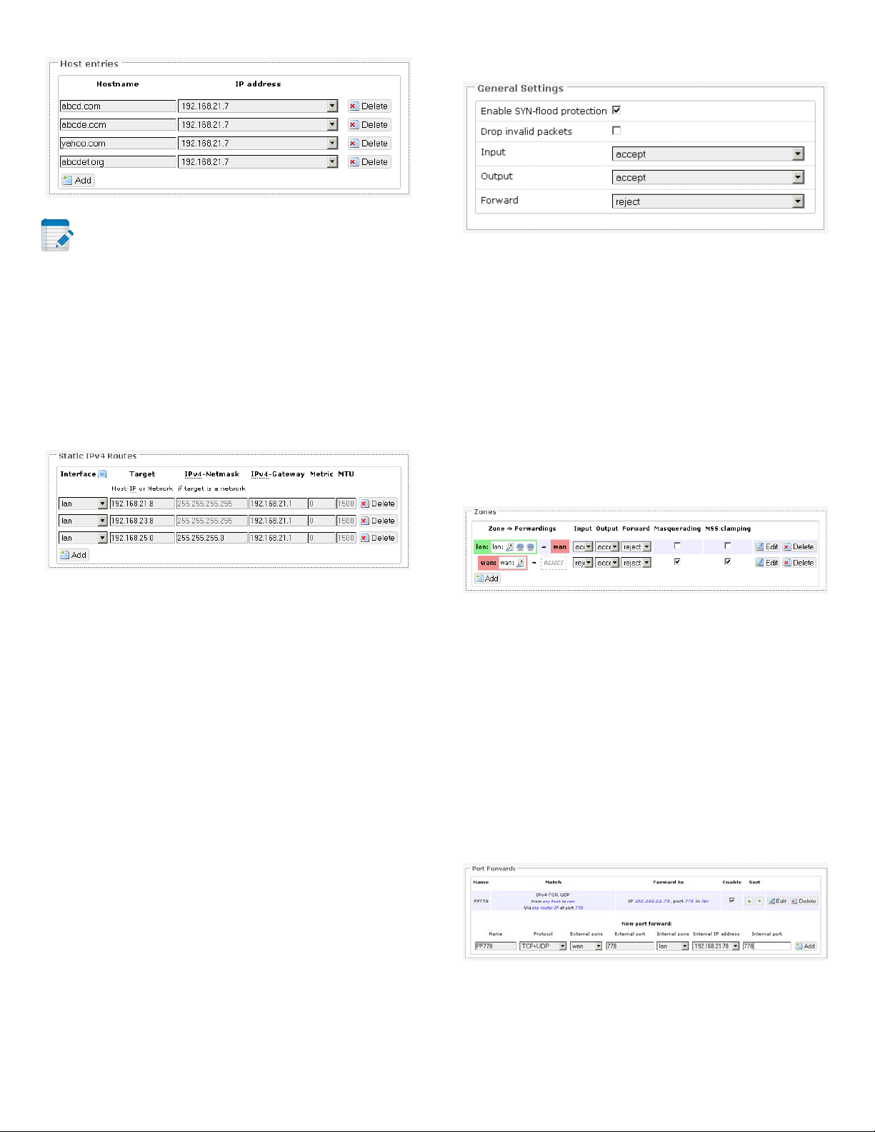
Zone Settings
settings for the firewall zones.
Figure 59: General Settings for the Firewall Zones.
Figure 57: Custom hostname entries.
Note: The computers in the same subnet need
to set the IP address of this device as their preferred
DNS server in order to interpret these custom
hostnames.
5.7 Static Routes
The Network → Static Routes page shows the static
IPv4 routes.
Figure 58: Static IPv4 Routes.
Each row shows the interface and gateway over which
a certain host or network can be reached.
Enable SYN-flood protection: Checked by default.
Drop invalid packets: Unchecked by default.
Input: To accept by default.
Output: To accept by default.
Forward: To reject by default.
Zones
Figure 60: The Zones section showing the default
5.8.2 Port Forwards
5.8 Firewall
Port forwarding allows remote computers on the
The Network → Firewall page contains the subpages
for General Settings, Port Forwards, and Traffic Rules.
5.8.1 General Settings
The firewall creates zones over the network interfaces
to control network traffic flow.
The Network → Firewall → General Settings page
contains the zone settings.
Altum AC 600 User Manual LT-9064 Rev A 33
Internet to connect to a specific computer or service
within the private LAN.
The Network → Firewall → Port Forwards page lets
you define the protocol and port number to access an
internal IP address.
Figure 61: Adding a port forwarding rule.
Page 34
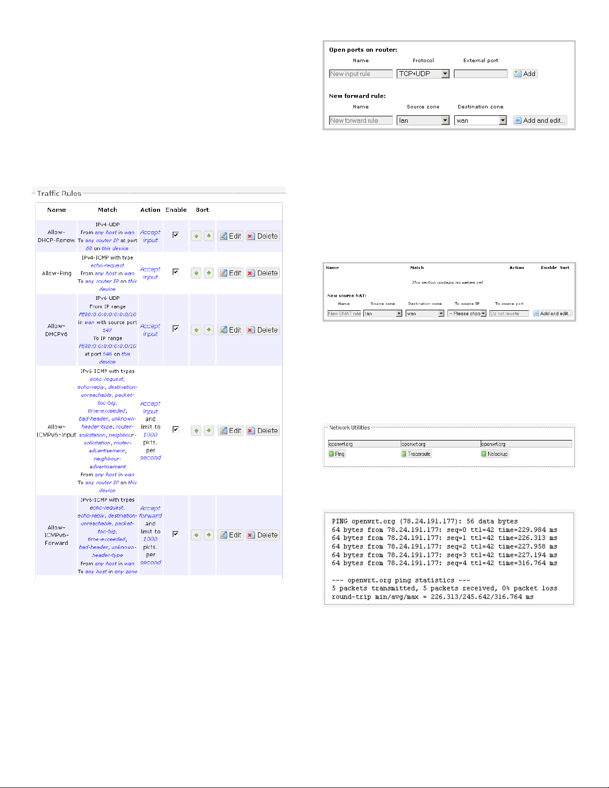
5.8.3 Traffic Rules
settings.
The Network → Firewall → Traffic Rules page
configures the traffic rules and source NAT.
Traffic Rules
Traffic rules define policies for packets travelling
between different zones, for example to reject traffic
between certain hosts or to open WAN ports on the .
Figure 63: You can choose to open ports on the or
add new forwarding rules.
Source NAT
Source NAT is a specific form of masquerading which
allows fine grained control over the source IP used for
outgoing traffic, for example to map multiple WAN
addresses to internal subnets.
Figure 64: Source NAT.
5.9 Diagnostics
5.9.1 Network Utilities
Figure 65: Network Utilities consist of Ping,
Traceroute, and Nslookup.
Figure 62: Firewall Traffic Rules with the default
Figure 66: Result of Ping.
34 LT-9064 Rev A Altum AC 600 User Manual
Page 35
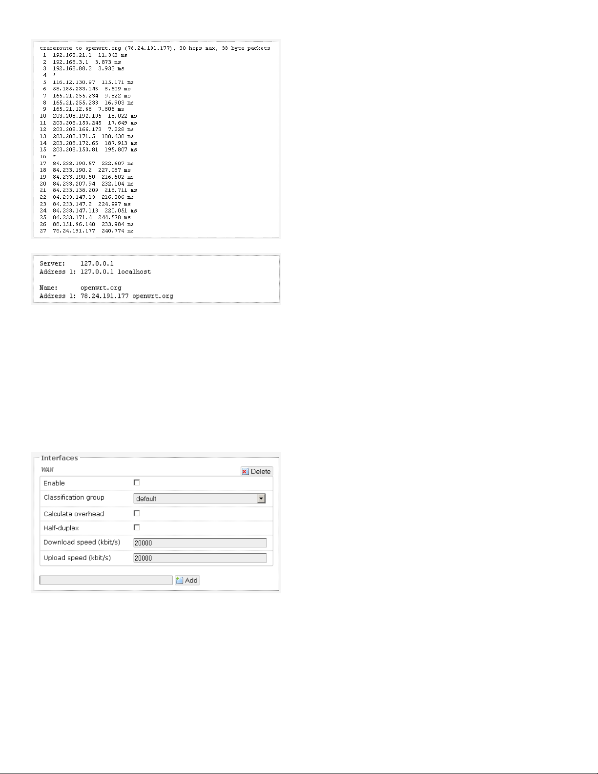
Figure 69: Network QoS settings.
Figure 67: Result of Traceroute.
Figure 68: Result of
.
Nslookup
5.10 Quality of Service
The Network → QoS page configures the quality of
service (QoS). With QoS, you can shape network
traffic selected by addresses, ports, or services. You
can limit the download and upload speeds. Network
QoS is disabled by default.
Altum AC 600 User Manual LT-9064 Rev A 35
Page 36
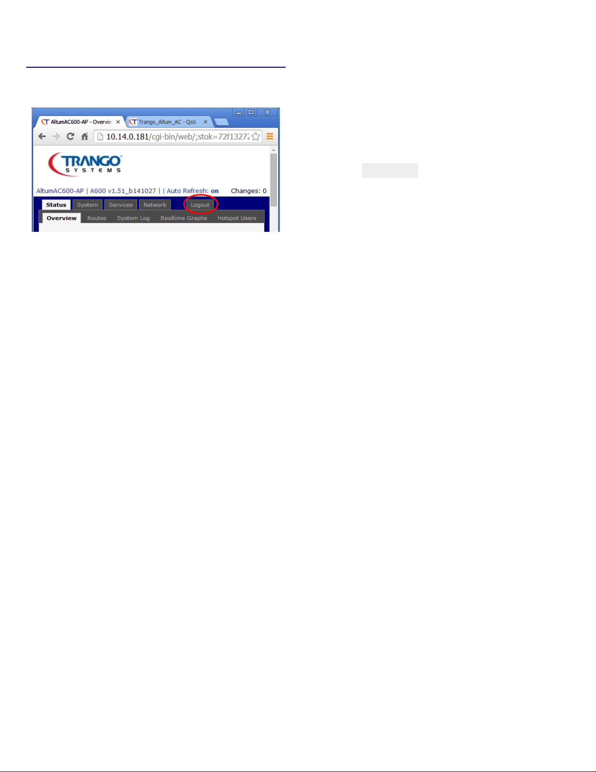
Chapter 6: Final Notes
Figure 70: The Logout button is circled.
Logout: Logs out of the radio's web page.
• ping 192.168.3.77 (if your computer's
IP address is 192.168.3.77 for example.)
They should be able to give the ping responses.
An IP address conflict would cause unstable pings.
Switch to another address and ping the conflicting
address to check.
If using a Windows computer, you should run the
command arp -d * if the network configuration
has changed. This is to delete the address resolution
protocol (ARP) table in Windows as it may not update
fast enough. This also applies if multiple radio units
with the factory default IP address are being set up all
at the same time. After configuring each radio, run
the arp –d command from your PC.
6.1 Troubleshooting steps
6.1.1 PC cannot connect to the radio
The configuration web page for the radio will not be
able to show up if the radio and your computer are
not connected.
If the PC and the radio are joined to the network by
LAN cables, they will not be able to connect if any of
the network cable connections are loose. A possible
indicator is that there is no light at the LAN port of
the PC. In Windows, if you click the network icon and
click to “View network connections”, the LAN port
shows “Disconnected”. Please ensure that all the
connections are tight.
Sometimes, disconnecting and reconnecting the LAN
cable solves connection problems if DHCP is used,
because the DHCP server and DNS server are reset.
The radio, the computer, and the gateway must have
IP addresses on the same network. For example, if
you use a subnet mask of 255.255.255.0 and the
gateway IP address is 192.168.3.1, all the IP addresses
must be unique and be of the form 192.168.3.X.
If the ping still cannot get responses, try disabling the
firewall on your Windows computer. The Windows
Firewall on your computer may prevent it from
sending back a ping response. Disabling the firewall
may be a security risk, so you should take the
precaution of disconnecting the Internet first.
6.1.2 PC Ethernet and Wifi adapters
If your PC has both Ethernet and Wifi adapters, they
must not have the same subnet. Otherwise, packets
from the PC may not be directed to the correct
network.
6.1.3 Mobile phone cannot connect
A mobile phone or any Wifi user would not be able to
connect to a wireless network if there does not exist a
DHCP server on the network. Please make sure that
there is one, and only one, DHCP server to assign IP
addresses automatically to users.
You may refer to Section 5.2.2 to enable the DHCP
server for a . The option is found in Network →
Interfaces → LAN → DHCP Server.
Check whether the radio and computer are connected
on the same network by running the ping command
to ping the IP address of the radio. Alternatively, type
the following in the radio's Linux terminal:
36 LT-9064 Rev A Altum AC 600 User Manual
Page 37
6.1.4 Mobile phone connects but cannot
access Internet
Solution: Turn off the radio for 10 seconds and then
turn it on again.
A mobile phone or any connected Wifi user would
not be able to access the Internet if the default
gateway is not set correctly on the radio.
The option for the default gateway is found in
Network → Interfaces → LAN → Common
Configuration → General Setup → IPv4 gateway.
If this radio has enabled a DHCP server but the
gateway is at a different IP address please add a DHCP
option according to Section 5.2.2 .
The DNS server should also be set. This option is
found in Network → Interfaces → LAN → Common
Configuration → General Setup → Use custom DNS
servers.
6.1.5 Unresponsive web page
Symptom: The 'XML Parsing Error' may occur if a
certain option was changed and the web page did not
update in time.
6.2 Resetting to factory default
To reset the radio to the factory default settings,
while the power is on, hold down the reset button for
8 seconds and then release.
Another method is to enter the following command
into the radio's Linux terminal:
• mtd -r erase rootfs_data
After a while, the flash would be erased and the radio
would reboot into its factory default state. The
firmware version remains the same as the latest
firmware loaded onto the board.
Figure 71: XML Parsing Error.
Solution: Re-enter the IP address into the browser.
This would bring you back to the login page of the
device.
6.1.6 Unresponsive
Symptom: The radio does not respond.
Altum AC 600 User Manual LT-9064 Rev A 37
Page 38

Glossary
Term
Definition
Access
A device that provides network access
ACK
Acknowledgment. This is a response to a
dB
Decibels. This is a measure of intensity.
dBm
addresses dynamically so that addresses
Term
Definition
private network.
protocol used by web browsers and web
IP
Internet Protocol. This is the primary
datagrams) across an internetwork using
Point
(AP)
ARP
CHAP
CPE
to associated stations (connected
wireless devices). Altum AC can function
as an AP.
transmission to indicate that the data
packet was received correctly.
Address Resolution Protocol. This is a
broadcast protocol for mapping IP
addresses to MAC addresses.
Challenge-Handshake Authentication
Protocol. This is a protocol for
authenticating users to an ISP.
Customer-Premises Equipment. This is
also known as a station.
EIRP
ESSID
FTP
HTTP
Equivalent Isotropic Radiated Power.
Each country sets the legally permitted
maximum for the EIRP limits on each
channel.
Extended Service Set Identifier. This is
the name of the wireless network. It is
case-sensitive and up to 32
alphanumeric characters in length. The
ESSID differentiates one wireless
network from another. All access points
and devices trying to connect to a
specific wireless network should use the
same ESSID (and password) to enable
effective roaming.
File Transfer Protocol. This is a protocol
for transferring files between network
nodes.
Hypertext Transfer Protocol. This is a
servers to transfer files.
Decibel-milliwatts. This is a measure of
power relative to 1 mW. This is
commonly used to measure wireless
signal power. A higher power leads to
communications protocol used for
relaying network packets (also known as
better signal quality.
the Internet Protocol Suite. IP is
DDNS
DHCP
Dynamic DNS. This is a system for
updating domain names in real time. It
allows a domain name to be assigned to
a device with a dynamic IP address.
Dynamic Host Configuration Protocol.
This is a protocol for allocating IP
ISP Internet Service Provider.
L2TP
responsible for routing packets across
network boundaries. It is the principle
protocol that establishes the Internet.
Layer 2 Tunneling Protocol. This is a
tunneling protocol used to support
can be reused when hosts (e.g.
computers) no longer need them.
virtual private networks (VPNs) or as
part of the delivery of services by ISPs. It
does not provide any encryption or
DNS
Domain Name System. This is a
distributed and hierarchical naming
system for computers, services, or any
resource connected to the Internet or a
38 LT-9064 Rev A Glossary
LAN Local Area Network.
confidentiality by itself. Rather, it relies
on an encryption protocol that it passes
within the tunnel to provide privacy.
Page 39

Term
Definition
Layer 2
MAC
MiniPCIe
Mini Peripheral Component
Interconnect Express. A miniPCIe radio is
MTU
Maximum transmission unit. This is the
NAT
NMS
manager. It is sometimes simply referred
NTP
PAP
Term
Definition
ISP having to manage the allocation of IP
RADIUS
Remote Authentication Dial In User
schema, and a set of data objects. SNMP
Station
A device that connects wirelessly to an
Address
Data link layer of the Open Systems
Interconnection (OSI) model. This
corresponds to the Link layer of the
Internet protocol suite.
Media Access Control Address. This is a
globally unique identifier attached to a
network adapter. It also identifies the
hardware manufacturer.
PPTP
network of hosts to an ISP without the
addresses.
Point-to-Point Tunneling Protocol. This is
a protocol for the creation of VPNs for
the secure transfer of data from remote
clients to private servers over the
Internet.
Mbps
PPPoE
Megabits per second. Also Mbit/s. This
is a measure of the data rate.
a radio card that can be inserted into a
unit's circuit board.
size, in bytes, of the largest packet that
can be passed on. The MTU for Ethernet
is a 1500-byte packet.
Network Address Translation. This is the
process of rewriting IP addresses as a
packet passes through a controller or
firewall. NAT enables multiple
computers (or hosts) on a LAN to access
the Internet using the single public IP
address of the LAN's gateway controller.
Network Management Station. This is a
software which runs on the SNMP
to as an SNMP manager.
Network Time Protocol. This is a
protocol for synchronizing a controller
to a single clock on the network, known
as the clock master.
Password Authentication Protocol. This
is a protocol for authenticating users to
a remote access server or ISP.
Point-to-Point Protocol over Ethernet.
This is a protocol for connecting a
QoS
SNMP
SSID
Quality of Service. This is the
prioritization of network traffic. Voice
traffic gets the highest priority, followed
by video, best effort, and background
traffic, in this order.
Service. This is a networking protocol
that provides Authentication,
Authorization, and Accounting (AAA)
management for remote users. The
RADIUS provides centralized
management of usernames and
passwords.
Simple Network Management Protocol.
This is an Internet-standard protocol for
managing devices on IP networks. It
consists of a set of standards for
network management, including an
application layer protocol, a database
exposes management data in the form
of variables on the managed systems,
which describe the system
configuration. These variables can then
be queried (and sometimes set) by
managing applications.
Service Set Identifier. This is also known
as the ESSID or the wireless network
name.
access point.
Glossary LT-9064 Rev A 39
Page 40

Term
Definition
Subnet
A portion of a network that shares a
common address component. On TCP/IP
TCP
WAN
Wide Area Network. This is a network
WDS
IEEE 802.11 network. It allows a wireless
requirement for a wired backbone to
Term
Definition
link them.
UDP
VAP
networks, subnets are defined as all
devices whose IP addresses have the
same prefix. For example, all devices
with IP addresses that start with
192.168.7 belong to the same subnet.
Transmission Control Protocol. This is a
protocol for transmitting data over the
Internet with guaranteed reliability and
in-order delivery.
User Datagram Protocol. This is a
protocol for transmitting data over the
Internet quickly but with no guarantee
of reliability or in-order delivery.
Virtual Access Point. A VAP simulates a
physical access point. A VAP is
configured on a per-radio basis. By
default, only one VAP is enabled. Up to
16 VAPs can be created for each radio,
each with its own SSID.
WLAN Wireless Local Area Network.
VPN
Web
Browser
Virtual Private Network. This is a
network that enables IP traffic to travel
securely over a public TCP/IP network by
encrypting all traffic from one network
to another. The VPN uses tunneling to
encrypt all information at the IP level.
that covers a broad area. The world's
most popular WAN is the Internet.
A software that allows the user to surf
the Internet.
Wireless Distribution System. This is a
system enabling the wireless
interconnection of access points in an
network to be expanded using access
points without the traditional
40 LT-9064 Rev A Glossary
Page 41

FCC Information
FCC ID: NCY-A600
The Altum AC600 System can be used for point-topoint operation.
NOTE: All Altum AC600 models require
professional installation due to FCC limits on
output power settings when operating in the
UNII bands.
This device complies with Part 15 of the FCC
Rules and Regulations. Operation is subject to
the following two conditions: (1) This device may
not cause harmful interference, and (2) this
device must accept any interference received,
including interference that may cause undesired
operation.
This equipment has been tested and found to
comply with the limits for a Class B digital device,
pursuant to Part 15 of the FCC Rules. These limits
are designed to provide reasonable protection
against harmful interference in a residential
installation. This equipment generates, uses, and
can radiate radio-frequency energy and, if not
installed and used in accordance with these
instructions, may cause harmful interference to
radio communications. However, there is no
guarantee that interference will not occur in any
particular installation. If this equipment does
cause harmful interference to radio or television
reception, which can be determined by turning
the equipment off and on, the user is encouraged
to correct the interference by one of more of the
following measures:
1) Reorient the antenna.
2) Increase the separation between the affected
equipment and the unit.
3) Connect the affected equipment to a power
outlet on a different circuit from that which the
receiver is connected to.
4) Consult the dealer and/or experienced
radio/TV technician for help.
WARNING:
Intentional or unintentional changes or modifications
must not be made unless under the express consent
of the party responsible for compliance. Any such
modifications could void the user’s authority to
operate the equipment and will void the
manufacturer’s warranty. To comply with RF exposure
requirements, the following antenna installation and
device operating configurations must be satisfied. The
antenna for this unit must be fixed and mounted on
outdoor permanent structures with a separation
distance of at least 143.51cm from all persons.
Furthermore, it must not be co- located or operating
in conjunction with any other antenna or transmit t e r.
Warranty Information
Radios from Trango Systems are warranted for one
year from date of purchase. Please see
www.trangosys.com
warranty coverage and limitations
for a complete description of
Glossary LT-9064 Rev A 41
 Loading...