

Page 1

EAGLE PLUS
______________________________________________________________________________________
2.4 GHz Wireless Vide o/Audio/Data Transmission System
Installation and Operating Instructions
Page 2
1• Verify proper operation of camera and monitor/event recorder using coaxial cable prior
to installing wireless link.
2• Install transmitter and receiver units in desired location to 2 3/8” diameter steel pole per
installation drawing. The pole must be securely mounted so that it does not move.
3• Install antennas above the enclosures and position as shown in Figure 2.
WARNING
WARNING
WARNINGWARNING
USE EXTREME CARE WHEN INSTALLING ANTENNAS NEAR POWER LINES.
4• Slide heatshrink over antenna cable. Tighten antenna cable to receiver and transmitter.
Heat up the heatshrink until it contracts a r o und the connector junction..
5• Connect video, audio, power, alarm, PC interface cables as needed to units through
flanges. Tighten flanges to allow small air gap at bottom of enclosure.
IMPORTANT NOTE:
Power adapter must be kept dry.
6• Verify that LEDs are lit up and transmitter and receiver are on same channel.
7• Tighten lid of enclosure down.
CAUTION
CAUTION
CAUTIONCAUTION
DO NOT APPLY POWER TO THE TRANSMITTER UNLESS THE ANTENNA IS
CONNECTED. PERMANENT DAMAGE MAY RESULT.
2
Copyright © 1999 Trango Systems, Inc. All rights reserved.
Page 3

Congratulations on choosing Trango Systems, Inc. to fulfill your wireless video needs. Unpack
your system carefully. If any items are missing, notify your sales representative. If an item
appears to be damaged from shipment, replace it in its packing material and notify the shipper.
Save the packaging for further storage of the equipment.
Service:
If the unit ever needs repair service, contact Trango Systems customer service at (858)
653-3900 for return authorization and shipping instructions.
FCC Information:
Note: This equipment has been tested and found to comply with the limits for a Class B
digital device, pursuant to Part 15 of the FCC Rules. These limits are designed to
provide reasonable protection against harmful interference in a residential installation.
This equipment generates, uses, and can ra diate radio frequency energy, and if not
installed and used in accordance with these instructions, may cause harmful interference
to radio communications. However, there is no guarantee that interference will not
occur in a particular installation. If this equipment does cause harmful interference to
radio or television reception, which can be determined by turning the equipment off and
on, the user is encouraged to correct the interference by one of more of the following
measures:
1) Reorient the receiving antenna;
2) Increase the separation between the affected equipment and the receiver;
3) Connect the affected equipment to an outlet on a different circuit from that
which the receiver is connected to;
4) Consult the dealer and/or experienced radio/TV technician for help.
VTX2400: # NCYVTX2500
IMPORTANT NOTE:
Intentional or unintentional cha nges or modifications not express ly approved by the
party responsible for compliance must not be made. Any such modifications could void
the user’s authority to operate the equipment.
System Description:
The EAGLE PLUS Wireless Video System is a professional quality system designed for
sending composite NTSC or PAL video, audio, and alarm signals using 2.4 GHz wireless
technology. The system is ideal for permanent or temporary video links due to its
portable nature and easy installation. It is not designed for operation while in motion.
Copyright © 1999 Trango Systems, Inc. All rights reserved.
3
Page 4

• FIGURE 1 •
Figure 1 shows the most common connection diagram for setting up a wireless video link
using the EAGLE PLUS.
NOTE: Make sure that your camera and monitor/recorder work properly hardwired
before attempting to install the wireless link.
4
Copyright © 1999 Trango Systems, Inc. All rights reserved.
Page 5

Installation:
The EAGLE PLUS system is factory-configured for operation on channel 1 with alarms
operational and mono audio.
To obtain the best picture quality and transmission distance, the following rules of thumb
should be followed:
1) Mount the transmitter and receiver antennas above human and mechanical traffic,
the higher the better. A 10 foot steel mast on top of a building is typical. Make sure
that the mast is well grounded to earth ground with an 8 AWG or larger wire. For
maximum range, the transmit and receive antennas must be 15 to 20 feet above all
obstacles in the line of sight.
2) Keep the transmission path as open as possible. Objects such as walls and
metallic objects near the transmission path may reduce the transmission distance.
3) Do not add additional lengths of cable to connect the receiver to the antenna as
significant losses in signal, and reduced transmission range will occur.
4) Keep the cable connecting the antenna to the receiv er as sh ort as possib le.
The EAGLE PLUS transmitter and receiver units come pre-mounted in a NEMA-4X
rated aluminum enclosure which allows mounting of the unit outdoors.
Copyright © 1999 Trango Systems, Inc. All rights reserved.
5
Page 6
Figure 2 shows the front panel of the VTX2500 transmitter and the functions of each control and
input/output. Each control is described in greater detail below.
IMPORTANT NOTE: The transmitter uses a non-standard jack to connect to
the transmitter antenna. Any modification to this jack may void the user’s
authority to operate the equipment and will void the manufacturer’s warranty.
CAUTION
CAUTION
CAUTIONCAUTION
DO NOT APPLY POWER TO THE TRANSMITTER WITHOUT THE
ANTENNA SECURELY ATTACHED. DO NOT APPLY VOLTAGE TO
THE ALARM PINS. DAMAGE TO THE UNIT MAY RESULT.
• FIGURE 2•
6
Copyright © 1999 Trango Systems, Inc. All rights reserved.
Page 7

2.4GHz Transmitter Inputs & Controls:
VIDEO INPUT
Designed to mate to a standard BNC male connector, this input accepts 1 Volt peakto-peak video in both NTSC and PAL formats. This input is terminated with 75 Ω.
RCA to BNC adapters are available for use with some cameras and VCRs.
AUDIO INPUT
Designed to mate to a standard RCA male connector, this input accepts 1 Volt peakto-peak audio input and is terminated with 600 Ω unbalanced configuration. It is
designed to be interfaced to “lineout” audio sources. A preamplifier must be used to
connect a microphone to this input.
DATA INTERFACE
When connected to a personal computer via the optional CBLDAT-1 interface cable,
this input accepts serial commands that control settings in the transmitter not
available on the front panel. See the Trangolink software program help for more
information.
POWER INPUT
Accepts a 6-12 Vdc power source such as the standard 7 Vdc adapter (Trango part
number PT07800-1), or an optional battery. The nominal current draw is 150
milliamperes. If using an adapter from a third party, use a well-regulated 200 mA
minimum output supply. Do not use the PT07800-1 to power a camera.
ALARM INPUTS
These inputs are used to send alarm signals to the receiver. They sense an open or
closed state and reflect that state to the receiver whenever it changes. The alarm
inputs operate independently of each other.
CAUTION
CAUTION
CAUTIONCAUTION
DO NOT APPLY EXTERNAL VOLTAGES TO THE ALARM INPUTS AS
PERMANENT DAMAGE TO THE UNIT MAY RESULT.
Copyright © 1999 Trango Systems, Inc. All rights reserved.
7
Page 8

2.4GHz Transmitter Operation:
Changing Channels:
To change channels, simply depress the Toggle/Standby switch momentarily until the
LED for the desired channel pattern is lit up. Remember to change the receiver
channel as well, since it is not automatically changed when the transmitter channel is
changed. For increased isolation from nearby systems operating on different
channels and multiple systems transmitting along the same path, the system can be
operated using right hand polarization on channels 1 and 3, and left hand polarization
on channels 2 and 4 (Additional equipment may be required).
Standby Mode:
This mode of operation does the following:
1) Places the transmitter into a low power mode.
2) Stops transmitting the RF signal.
3) Continues to monitor the alarm inputs that have been armed (Factory default --
both inputs are armed).
4) Monitors the data port for control signals from the TrangoLink software.
While in Standby mode, if an alarm state change occurs, the transmitter will come
out of Standby mode instantly, begin transmitting the video signal, and change the
receiver alarm output state to reflect the changed state on the transmitter. The unit
will not return to standby mode unless the user holds the toggle button down or
commands the unit via Trangolink.
ENTERING STANDBY MODE
To enter the Standby mode, the user must hold down the Toggle/Standby switch for 2
seconds. The status LED will blink once per second for about 1 minute to allow the
operator to leave the area. During this time the alarms will be disarmed. After 1
minute, the alarms will be armed, and the active channel LED will then blink at a rate
of about once every 2 seconds to indicate that the unit is in Standby mode, and
waiting for an alarm state change to occur.
EXITING STANDBY MODE
To exit Standby mode, the user must simply depress the Toggle/Standby switch
momentarily. After exiting Standby mode, the active channel LED will be on solid
to indicate that the video signal is being transmitted normally. Alarms will still be
armed unless the are turned off via the Trangolink software.
LOW BATTERY
If the input voltage drops below 6V, the active channel LED will blink twice per
second. A low battery indication is also sent to the receiver and can be viewed using
the TrangoLink software or the receiver. No alarm is generated.
8
Copyright © 1999 Trango Systems, Inc. All rights reserved.
Page 9

Figure 3 shows the front panel of the VRX2500 receiver and the functions of each control and
input/output.
• FIGURE 3 •
Copyright © 1999 Trango Systems, Inc. All rights reserved.
9
Page 10

2.4GHz Receiver Inputs/Outputs & Controls:
VIDEO OUTPUT
Designed to mate to a standard BNC male connector, this provides a 1 Volt peak-topeak video signal output. This must be terminated with 75 Ω. RCA to BNC adapters
are available for use with some monitors and VCR inputs.
AUDIO OUTPUT
Designed to mate to a standard BNC male connector, this provides a 1 Volt peak-topeak audio output and should be terminated in a 600 Ω load, as is found in most “line
in” audio inputs. RCA to BNC adapters are available for use with some monitors and
VCR inputs.
DATA INTERFACE
When connected to a personal computer via the optional CBLDAT-1 interface cable,
this input accepts serial commands that control settings in the receiver not available
via the front panel. See the Trangolink software program help for more information.
POWER INPUT
Accepts a 12 Vdc power source such as the standard 12 Vdc adapter (Trango part
number PT12500-1), or an optional battery. The nominal current draw is 350
milliamperes. If using an adapter from a third party, use a well-regulated
12Vdc/500mA output supply.
ALARM OUTPUT
This is a relay output which can sink 1 ampere at 40 V AC/DC. When a valid alarm
condition is received from the transmitter, this output will close to ground. This
output can be used to turn on peripheral devices such as video recorders and audible
alarms.
ALARM CLEAR INPUT
This input allows the operator to clear an alarm which has been received. This input
is normally open, and will clear the alarm upon closure to ground.
CAUTION
CAUTION
CAUTIONCAUTION
DO NOT APPLY EXTERNAL VOLTAGES TO THE ALARM OUTPUT OR
ALARM CLEAR PINS. PERMANENT DAMAGE TO THE UNIT MAY
RESULT.
10
Copyright © 1999 Trango Systems, Inc. All rights reserved.
Page 11

2.4GHz Receiver Operation:
Changing Channels:
To change channels, simply depress the Toggle/Standby switch momentarily until the
LED for the desired channel pattern is lit up. Remember to change the receiver
channel as well, since it is not automatically changed when the transmitter channel is
changed. For best performance, multiple systems transmitting along the same path
should be operated using horizontal polarization on channels 1 and 3, and vertical
polarization on channels 2 and 4.
Alarm Conditions:
When the VRX2400 receives an alarm condit ion from the transmitter, the active
channel LED will begin blinking.
If Alarm 1 is activated, then the active channel LED blinks once be tween pauses.
If Alarm 2 is activated, then the active channel LED blinks twice between pauses.
If both alarms have been activated, then the active channel LED blinks three times
between pauses.
The active channel LED will stop blinking when the alarm condition is cleared.
RSSI Mode:
To ease alignment of the receiver antenna, the received signal strength may be
viewed by placing the unit in RSSI mode. The LEDs will then act as a bar-graph
indicator, with more LEDs lit for a stronger signal.
To enter RSSI mode, hold down the Toggle/RSSI button for 2 seconds. To exit,
depress the button momentarily. The number of LEDs lit is a relative indication of
signal strength to be used only to find the best antenna position. Viewing the
received picture quality should be used in conjuction with this mode.
Copyright © 1999 Trango Systems, Inc. All rights reserved.
11
Page 12

INTERFERENCE
If interference such as lines in the pictures is observed, changing the transmission
channel may cure the problem.
Also, AC generators in close proximity to the transmitter or receiver may cause lines
in the picture. Move the unit away from the source of the interference.
NO PICTURE
Check that the transmit and receive channels are set the same, and make sure the
transmitter is not in Standby mode (slow, blinking LED), or that the battery is not
low (fast, blinking LED).
Verify all connectors are tig ht.
POOR PICTURE QUALITY
Raise transmitter and receiver antennas above ground and away from obstacles and
traffic, including foot traf fic .
Use an optional high-gain dish antenna on the receiver. Verify all connectors are
tight. Shorten the receiver antenna feed cab le.
VIDEO TOO DARK
Make sure that any monitors/peripheral equipment connected to the video source are
set to high impedance termination since the VTX2400 has a built-in 75 Ω
termination.
VIDEO TOO BRIGHT
Make sure that the receiver video output line is terminated with 75 Ω.
CAN’T COMMUNICATE WITH TRANSMITTER OR RECEIVER USING
TRANGOLINK
Perform a system reset by holding toggle switch down while applying power. All
memory locations will be erased and the system will be reinitialized. All LEDs will
light up to indicate a successful reset. Release the toggle switch.
12
Copyright © 1999 Trango Systems, Inc. All rights reserved.
Page 13
Overview:
TrangoLink™ allows you to configure and monitor your EAGLE, FALCON, or PTZ-900
transmitters and receivers. On the EAGLE and FALCON transmitters, you can change
the active channel, operating mode, and alarm triggering. On the EAGLE and FALCON
receivers, you can change the active channel and monitor the signal strength, transmitter
battery status, video loss, and alarm status. On the PTZ-900 transmitter and receiver, you
can configure the hopping sequence, the data rate, the mode, and the address as well as
monitor the signal strength.
PC Requirements & Installation:
In order to run TrangoLink, you will need Windows 95 or higher, 400 kB of free disk
space, and one free serial port.
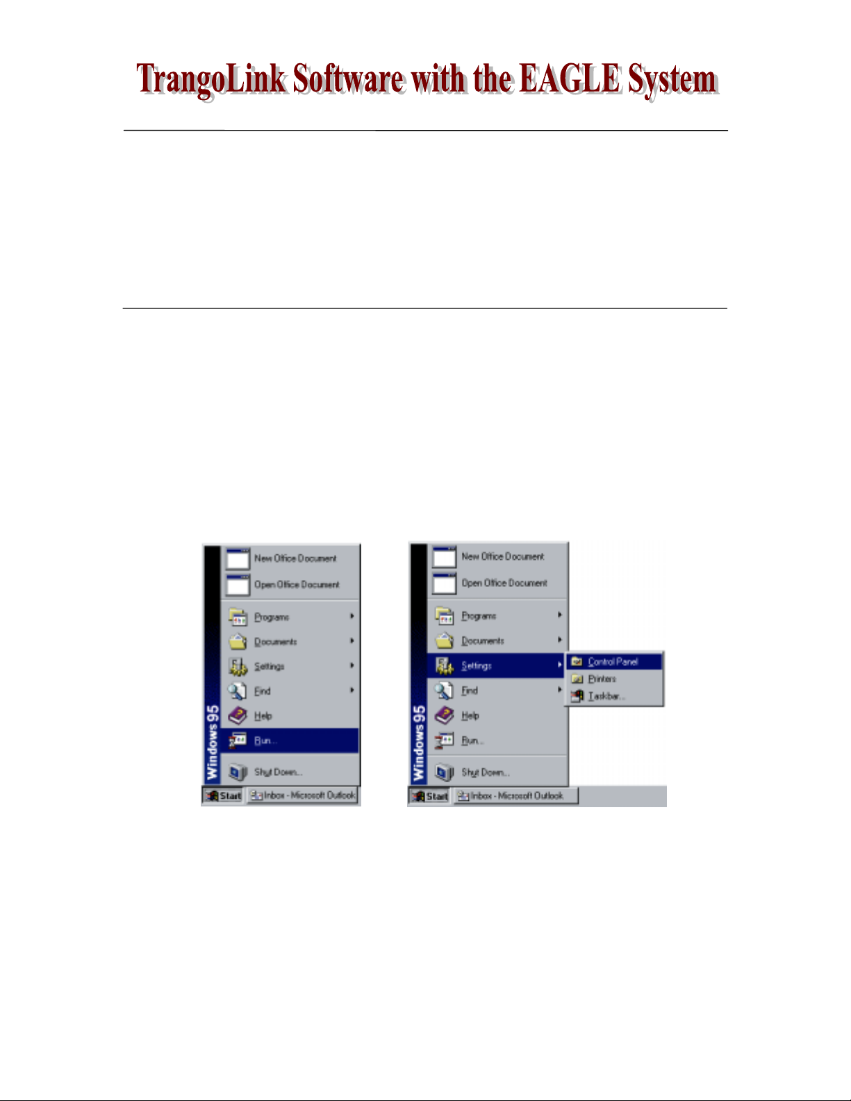
To install (see Fig. 4):
1. Start Win95 (or higher).
2. Click on Start, then Run.
3. Type a:\setup, then click OK.
To uninstall (see Fig. 5):
1. Click on Start, then Settings, then Control Panel.
2. Double click on Add/Remove Programs.
3. Select TrangoLink, and click Add/Remove.
Fig. 4 Fig. 5
Copyright © 1999 Trango Systems, Inc. All rights reserved.
13
Page 14
TrangoLink with the EAGLE System:
The TrangoLink software allows the user to change the user settings on the EAGLE
transmitters and receivers. The software runs under the Windows 95 or higher PC
platform and connects from either COM1 or COM2 to the Data interface on the
transmitter or receiver via the CBLDAT-1 interface cable.
To enter the program, the user must apply power to the connected unit and run the
TrangoLink program by clicking on the TrangoLink icon.
After entering the program, a screen is displayed showing the current settings. The user
may change the settings and then must click “Save Changes and Exit”. Upon exiting the
program and cycling power to the unit, the settings will become effective.
Configuring the EAGLE Transmitter:
Via the TrangoLink interface panel for the VTX2400 transmitter, the user can configure
the following settings:
Link Verification: This is a 32-bit code sent from the transmitter to the receiver to
verify that the signal is being received from the proper location.
Active Channel: This must be the same on the transmitter and receiver in order for
video to be transferred properly.
Standby Mode: When in standby mode, the transmitter shuts down the majority of
its circuitry until it is awakened by an alarm. Via TrangoLink, the transmitter can be
put into standby mode, or awakened from standby mode.
Alarm Arming and Polarity: Which of the alarms are active, and whether the
alarms activate open or closed. Via TrangoLink, alarms can also be sent to the
transmitters for testing and diagnostic purposes.
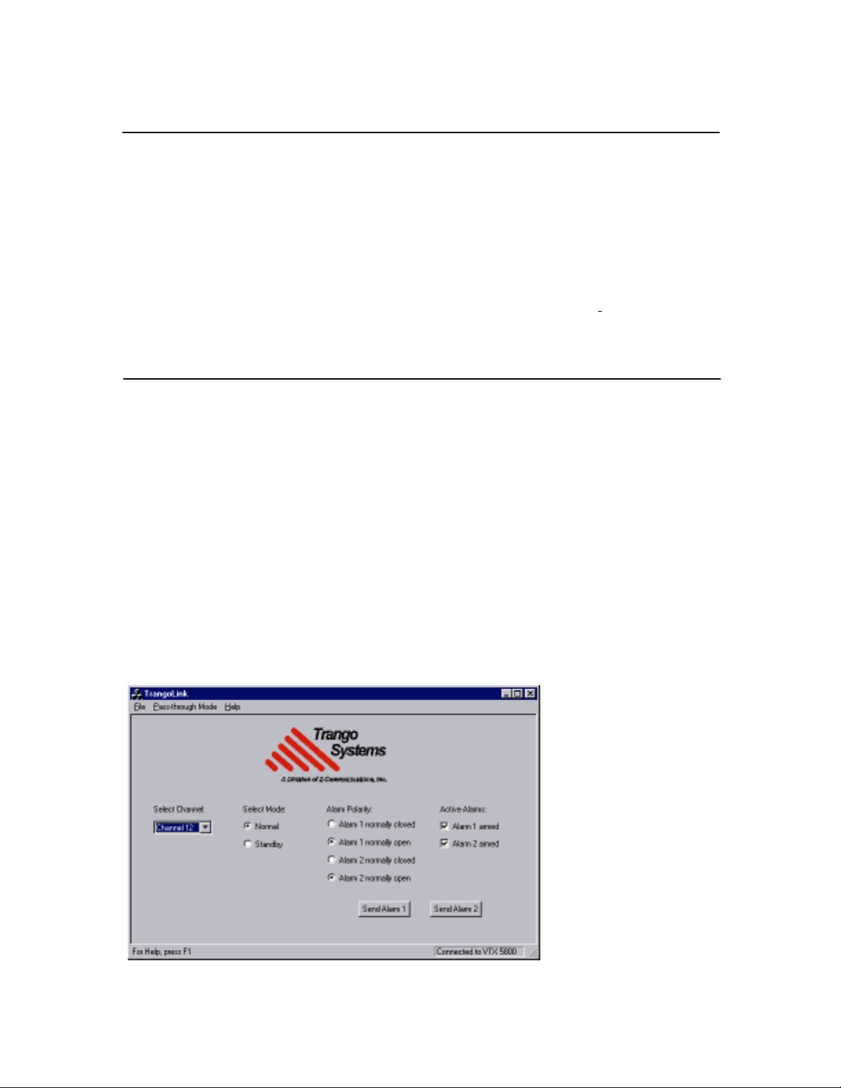
In Fig. 6, the TrangoLink
interface screen shows that
the transmitter is set to
Channel 12, in Normal
mode (not Standby), with
both alarms Armed and set
to alarm on closure.
Fig. 6
14
Copyright © 1999 Trango Systems, Inc. All rights reserved.
Page 15
Configuring the EAGLE Receiver:
Via the TrangoLink interface panel for the VRX2400 receiver, the user can configure the
following settings:
Link Verification: This is a 32-bit code sent from the transmitter to the receiver to
verify that the signal is being received from the proper location.
Alarms and Alarm Log: Via TrangoLink, the alarm log can be viewed, printed, or
saved to a file. You can also set which of the alarms are active, clear alarms, and
whether the alarms activate open or closed.
Active Channel and Channel Switching: This must be the same on the transmitter
and receiver in order for video to be transferred properly. Automatic channel
switching can also be configured to monitor several transmitters at once. Channels
can also be switched manually using TrangoLink.
RSSI: Used for receiver only to monitor the radio spectrum. Presents a histogram.
Useful in troubleshooting to determine if any other signals are present in the
frequency band.
Low Battery: Whether or not the battery is below voltage on the transmitter and is
hence in danger of failing.
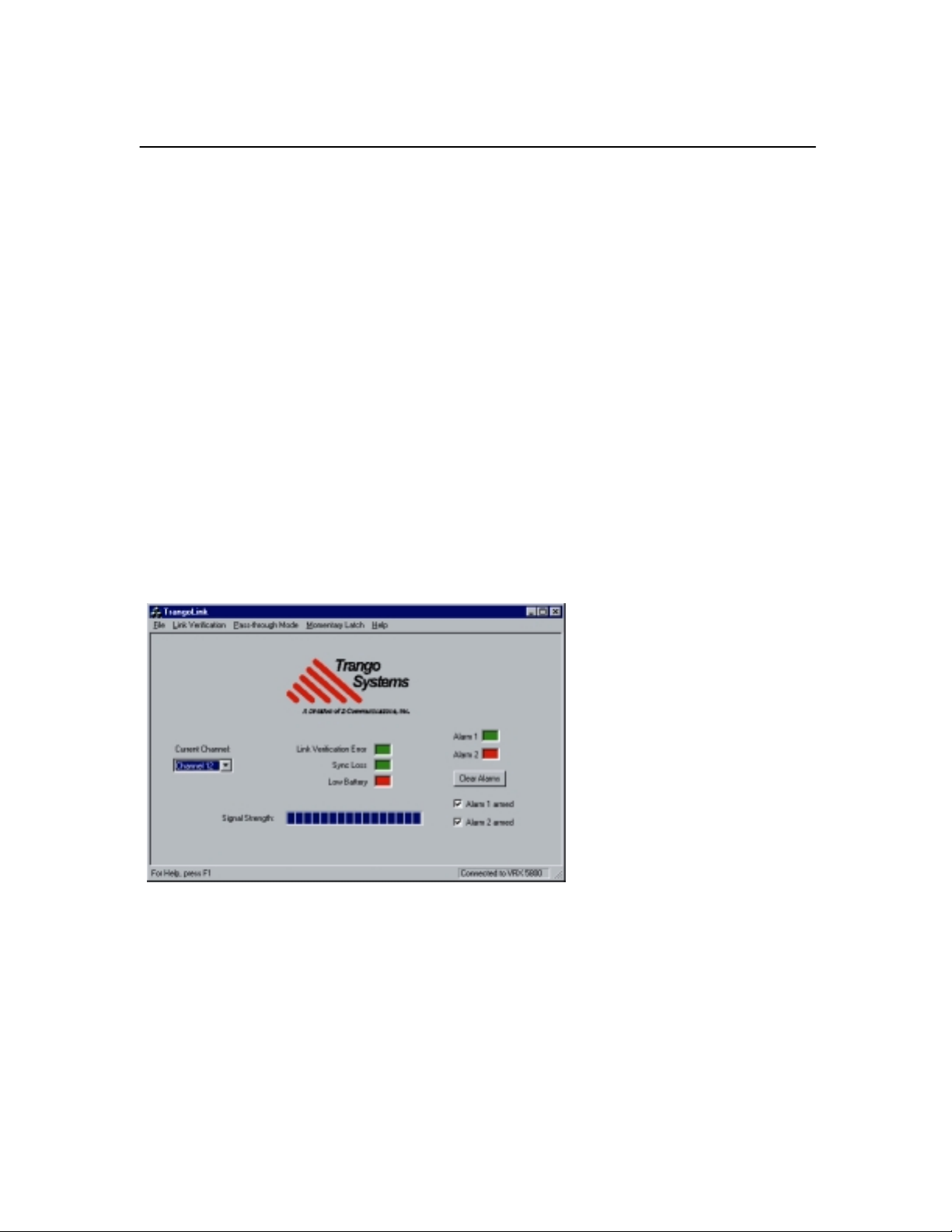
In Fig. 7, the TrangoLink
interface screen shows that the
receiver is set to Channel 12, and
is showing an alarm condition in
Alarm 2, and a low battery
condition on the transmitter.
Fig. 7
Copyright © 1999 Trango Systems, Inc. All rights reserved.
15
Page 16
VTX2500 Transmitter: Electrical
RADIO SECTION:
Frequencies: Channel 1: 2413 MHz
Channel 2: 2432 MHz
Channel 3: 2451 MHz
Channel 4: 2470 MHz
RF Output Power: Meets FCC Part 15.249 radiated field strength of 50 mV/m at 3
meters with CP omni or CP patch antenna provided with unit.
Frequency Stability: 0.005% PLL Stabilized (50 ppm) over temperature range
Frequency Plan: Direct carrier modulation
Modulated Bandwidth: 16 MHz (3 dB); 30 MHz (40 dB)
nd
Harmonic Attenuation: > 20 dBc (2
Spurious Attentuation: > 50 dBc
VIDEO SECTION:
Input Level: 1Vpp per NTSC/PAL standard
harmonic)
Input Impedance: 75Ω unbalanced
Modulation: Narrowband direct FM (for composite signal)
Modulation Index: 1.0 at 6.5 MHz for composite A/V signal (±6.5 MHz deviation)
Pre-emphasis: CCIR Rec 405-1
AUDIO SECTION:
Input Level: 1 Vpp Nominal
Input Impedance: 600 Ω
Bandwidth: 50 Hz – 15 kHz (3 dB)
Modulation: Wideband FM
Subcarriers: 6.0 MHz (right) and 6.5 MHz (left-monaural)
Modulation Index: 1.0 at 75 kHz for audio (±75 kHz deviation)
Pre-emphasis: 75 uS
16
Copyright © 1999 Trango Systems, Inc. All rights reserved.
Page 17

ALARM SECTION:
Input Level: Normally open contact closure input on both Alarm 1 and Alarm
Min. Alarm Duration: 1/2 second minimum to allow detection.
Max. Wire Length: 1000 ft from sensor to alarm input(s)
POWER SECTION:
Input Voltage: 7 Vdc nominal, 6-12 Vdc range
Current Consumption: 150 mA typical in normal mode, 10 mA in Standby mode
Max. Ripple Output: 2 Vpp
Low Battery Sens.: < 6 Vdc
2. The current state of the input (open or closed) is transmitted
to the receiver which reflects the transmitter alarm input states.
DO NOT APPLY VOLTAGES TO THESE INPUTS AS
DAMAGE TO THE UNIT WILL OCCUR.
Copyright © 1999 Trango Systems, Inc. All rights reserved.
17
Page 18

VTX2500 Transmitter: Mechanical & Environmental
GENERAL:
Material: Cast aluminum NEMA 4X rated outdoor enclosure
Finish: Off-white powdercoat
Size: 4.65” W x 8.8”L x 2.475”H without antenna
Weight: 2.65 lb
CONNECTORS & INDICATORS:
RF Output: Custom connector in compliance with FCC rules part 15C,
15.203.
FCC Compliance: The transmitter shall comply with FCC Part 15.249, FCC Part
15.207(a), FCC Part 15 Subpart B, Industry Canada
Specifications
PC Interface: 6 position, 4 conductor RJ11 female right angle PCB mount
Video: BNC female PCB mount
Audio: Red RCA female PCB mount – R Audio
Alarm/Power: 6 post terminal block (+7 Vdc, GND, ALARM1, ALARM 2)
Controls: Channel switch – momentary, toggles through modes/channels
Indicators: 4 channel LEDs that blink slowly in Standby mode and rapidly
ENVIRONMENTAL:
Operating Temp.: -20 to 70 ºC
Storage: -30 to 85 ºC
Humidity: 100% (enclosure)
Shock: Sustain 3-axis drop from 5’
White RCA female PCB mount – L Audio (Mono)
Stereo/Alarm switch: DPDT switch allows selection of
data/alarms or right audio on 6.0 MHz subcarrier
when battery is low
18
Copyright © 1999 Trango Systems, Inc. All rights reserved.
Page 19

VRX2500 Receiver: Electrical
RADIO SECTION:
LO Frequency: 1933-1990 MHz
Frequency Stability: 0.0025% PLL Stabilized (25 ppm) over temperature
Cascade P1dB Input: > -18 dBm
Cascade IP3 Input: > -5 dBm
IF Bandwidth: 16 MHz (3 dB)
Image Rejection: > 60 dB
Channel Rejection: > 20 dB between adjacent channels
> 90 dB between channels 1 and 4
> 60 dB between channels 2 and 4, 1 and 3
FM Threshold: -90 dBm
Cascade Noise Figure: < 5 dB
VIDEO SECTION:
Video 3dB BW: 5.8 MHz (Conforms with NTSC/PAL standard)
Video Output S/N: > 37 dB with –85 dBm RF input
Video Diff. Gain: < 10%
Video Diff. Phase: < 5 degrees
Chr. To Lum. Gain: 70% to 107%
Chr. To Lum. Delay: ±60 nS
Output Load Imp.: 75 Ω
DC Clamping: Back Porch with .15 V typical DC offset
> 40 dB with –80 dBm RF input
> 45 dB with –75 dBm RF input
Copyright © 1999 Trango Systems, Inc. All rights reserved.
19
Page 20

AUDIO SECTION:
Audio Bandwidth: 50 Hz to 15 kHz (3 dB)
Harmonic Distortion: < 10% over 50 Hz to 15 kHz
Audio Output S/N: > 15 dB with –80 dBm RF Input
Output Load Imp.: 600 Ω
Output Level: .8 to 1.75 Vpp
ALARM SECTION:
Data Rate: 1200 bps
Coding Scheme: 32 bit command/address, 8 bit data with checksum
Output Level: Reflects state of transmitter alarm inputs – updated twice per
POWER SECTION:
Input Voltage Range: 7 Vdc nominal, 6-9 Vdc
second
Max. Ripple Input: 2 Vpp
Current Consumption: 390 mA nominal in receive mode and RSSI mode
20
Copyright © 1999 Trango Systems, Inc. All rights reserved.
Page 21

VRX2500 Receiver: Mechanical & Environmental
GENERAL:
Material: Cast aluminum NEMA 4X rated outdoor enclosure
Finish: Off-white powdercoat
Size: 4.65” W x 8.8”L x 2.475”H without antenna
Weight: 2.65 lb
CONNECTORS & INDICATORS:
RF Input: SMA female connector
FCC Compliance: The transmitter shall comply with FCC Part 15.249, FCC Part
15.207(a), FCC Part 15 Subpart B, Industry Canada
Specifications
PC Interface: 6 position, 4 conductor RJ11 female right angle PCB mount
Video: BNC female PCB mount
Audio: Red RCA female PCB mount – R Audio
Alarm/Power: 6 post terminal block (+7 Vdc, GND, ALARM1, ALARM 2)
Controls: Channel switch – momentary, toggles through modes/channels
Indicators: 4 channel LEDs that blink slowly in Standby mode and rapidly
ENVIRONMENTAL:
Operating Temp.: -20 to 70 ºC
Storage: -30 to 85 ºC
Humidity: 100% (enclosure)
Shock: Sustain 3-axis drop from 5’
White RCA female PCB mount – L Audio (Mono)
Stereo/Alarm switch: DPDT switch allows selection of
data/alarms or right audio on 6.0 MHz subcarrier
when battery is low
Copyright © 1999 Trango Systems, Inc. All rights reserved.
21
 Loading...