

Trango Systems M900S User Manual

M900S™
900 MHz Wireless Broadband System
USER MANUAL
December 8, 2003
Revision A
-DRAFT-
for BETA Firmware Version 0.1

Table of Contents Trango
Table of Contents
Preface...............................................................................................................................................................................................iv
FCC Information.............................................................................................................................................................................iv
Warranty Information......................................................................................................................................................................iv
Section 1 Introduction.......................................................................................................................................................................1
Overview..........................................................................................................................................................................................1
SmartPolling™ Overview ................................................................................................................................................................1
Section 2 Hardware Overview...........................................................................................................................................................3
M900S AP and SU Hardware Components....................................................................................................................................3
Section 3 Getting Started..................................................................................................................................................................4
Connections and Power..................................................................................................................................................................4
Opmode and Radio Management Concepts...................................................................................................................................5
Browser Interface............................................................................................................................................................................6
Command Line Interface.................................................................................................................................................................8
Telnet..........................................................................................................................................................................................8
Troubleshooting..........................................................................................................................................................................8
Reset Button...............................................................................................................................................................................8
Section 4 Basic Configuration via Browser Interface ....................................................................................................................9
Configuring AP Subscriber Unit Database......................................................................................................................................9
Configure Other Basic AP Parameters..........................................................................................................................................11
Configure Basic SU Parameters ...................................................................................................................................................13
LED Summary...............................................................................................................................................................................13
Evaluate Link Quality.....................................................................................................................................................................14
RF Link Loopback Test .................................................................................................................................................................14
SU Ranging / RSSI Test................................................................................................................................................................15
Advanced Setup Page...................................................................................................................................................................15
Other Key Parameters...................................................................................................................................................................16
Site Survey Page...........................................................................................................................................................................17
Section 5 Basic Configuration via CLI...........................................................................................................................................18
Access Point Basic Settings ..........................................................................................................................................................18
Subscriber Unit Basic Settings......................................................................................................................................................20
Subscriber Unit Database Settings ...............................................................................................................................................21
Section 6 Mounting Hardware ........................................................................................................................................................23
Cabling and Grounding Considerations ........................................................................................................................................24
Section 7 Deployment......................................................................................................................................................................26
Site Selection.................................................................................................................................................................................26
Site Survey....................................................................................................................................................................................26
AP Search and SU Antenna Alignment.........................................................................................................................................27
Link Management Commands ......................................................................................................................................................28
Section 8 Management....................................................................................................................................................................32
SU Management from AP .............................................................................................................................................................32
TCP/IP of Radio at Other End of Wireless Link.............................................................................................................................32
Loading Multiple SUs into SUDB using DLOAD Command..........................................................................................................33
SNMP............................................................................................................................................................................................33
Objects for Monitoring and Control................................................................................................................................................33
SNMP Setup..................................................................................................................................................................................34
Appendix A Command Set Reference ...........................................................................................................................................36
Appendix B Specifications..............................................................................................................................................................38
Trango Broadband Wireless — Access5830 User Manual Rev. D page ii

Table of Figures Trango
Table of Figures
Figure 1-1 Typical Point-to-Multipoint Deployment..............................................................................................................................1
Figure -2-1 Basic Components of an M900S Radio............................................................................................................................3
Figure 2-2 Bottom of Radio..................................................................................................................................................................3
Figure 2-3 Back of Radio.....................................................................................................................................................................4
Figure 2-4 Side of Radio & Location of Reverse Polarity SMA Connector..........................................................................................4
Figure 3-1 Wiring Diagram...................................................................................................................................................................5
Figure 3-2 Browser Interface Login Page............................................................................................................................................6
Figure 3-3 Web Browser System Information Page.............................................................................................................................7
Figure 4-1 Bottom of M900S Radio with LEDs..................................................................................................................................14
Figure 5-1 Reference Table of Basic AP System Information...........................................................................................................18
Figure 5-2 Reference Table of Basic SU System Information...........................................................................................................20
Figure 6-1 M900S Mounting Hardware Assembly............................................................................................................................23
Figure 6-2 Alternative Mounting........................................................................................................................................................23
Figure 6-3 Articulation for M900S with Mono Pod Mount (not supplied) ...........................................................................................24
Figure 6-4 Grounding Example..........................................................................................................................................................24
Trango Broadband Wireless — M900S User Manual Rev. 1A page iii

Preface
Preface
This manual covers basic configuration and installation of the Access5830 Wireless Broadband System and applies to the following
radio part numbers:
M900S-AP 900 MHz Access Point
M900S-SU 900 MHz Subscriber Unit
FCC Information
This device complies with Part 15 of FCC Rules and Regulations. Operation is subject to the following two conditions: (1) This device
may not cause harmful interference and (2) this device must accept any interference received, including interference that may cause
undesired operation.
This equipment has been tested and found to comply with the limits for a Class B digital device, pursuant to Part 15 of the FCC Rules.
These limits are designed to provide reasonable protection against harmful interference in a residential installation. This equipment
generates, uses, and can radiate radio-frequency energy and, if not installed and used in accordance with these instructions, may
cause harmful interference to radio communications. However, there is no guarantee that interference will not occur in any particular
installation. If this equipment does cause harmful interference to radio or television reception, which can be determined by turning the
equipment off and on, the user is encouraged to correct the interference by one of more of the following measures:
1) Reorient the antenna;
2) Increase the separation between the affected equipment and the unit;
3) Connect the affected equipment to a power outlet on a different circuit from that which the receiver is connected to;
4) Consult the dealer and/or experienced radio/TV technician for help.
FCC ID: NCYM900S
IMPORTANT NOTE: Intentional or unintentional changes or modifications must not be made unless under the express consent of the
party responsible for compliance. Any such modifications could void the user’s authority to operate the equipment and will void the
manufacturer’s warranty. To comply with FCC RF exposure requirements, the following antenna installation and device operating
configurations must be satisfied. The antenna for this unit must be fixed and mounted on outdoor permanent structures with a
separation distance of at least two meters from all persons. Furthermore, it must not be co-located or operating in conjunction with any
other antenna or transmitter.
Warranty Information
Radios from Trango Broadband Wireless are warranted from one year from date of purchase. Please see www.trangobroadband.com
for complete description of warranty coverage and limitations.
Trango Broadband Wireless — M900S User Manual Rev. 1A page iv
Introduction
Section 1 Introduction
Your Trango Broadband M900S radio system provides a reliable and robust means to deliver broadband access and wireless Ethernet
connectivity to a wide geographic region. This section will familiarize you with basic operational concepts as well as an overview of the
hardware and the various components of the M900S system.
Overview
The M900S is a highly versatile and cost effective outdoor point-to-multipoint solution for wireless broadband service providers
enterprise connectivity applications. The M900S delivers 3 Mbps over the air, and operates in the 900 MHz ISM band. Each
radio includes an integrated built-in dual polarized (horizontal and vertical) antenna as well as a connector for the attachment of
an external antenna such as a yagi or an omni style antenna
The M900S system is classified as a Layer 2 multi-point bridge. Authentication of SUs is performed using a secure, proprietary
method at the MAC level, and thus all forms of Ethernet traffic and unlimited IP addresses will pass seamlessly over the system.
There is no limitation on the number of IP addresses or hardware devices that an individual SU may have physically connected to an
M900S radio.
Both APs and SUs can be easily configured and managed (either locally or remotely) through built in serial and Ethernet
interfaces, along with a web browser provisioning tool for quick set up and deployment. The M900S radios are powered using
"Power over Ethernet" for ease and low-cost installation. Both APs and SUs feature a handy "site survey" tool to check for
interference.
The M900S system consists of two types of radios: Access Points (AP) and Subscriber Units (SU). The AP unit acts as a hub in a star
configuration wireless multipoint network supporting up to 126 subscriber units. The AP delivers wireless broadband service (Ethernet
connectivity) to one or more SUs according to a proprietary adaptive dynamic polling algorithm called SMARTPolling™ Network
operators can co-locate multiple APs at a single cell site, thus increasing the aggregate throughput available at each wireless point of
presence (POP).
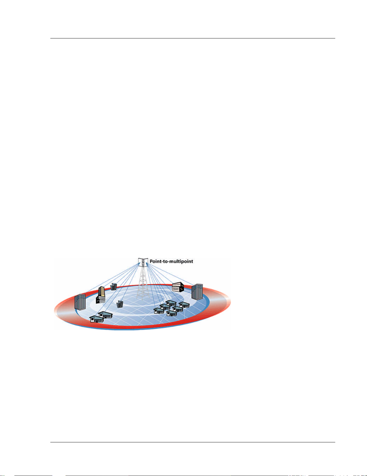
Figure 1-1 Typical Point-to-Multipoint Deployment
The M900S AP provides a host of comprehensive tools and functions. The AP typically resides at the center of the point-to-multipoint
(PMP) network and performs all management functions including the allocation of bandwidth for all associated SUs.
SmartPolling™ Overview
One of the major advantages of the M900S system is the ability of the AP to handle multiple SU connections and share the
3 Mbps data throughput very efficiently. Bandwidth allocation is managed by the AP’s SMARTPolling algorithm according to
provisioning rules set up by the system administrator. The AP polls each SU in a round robin format to determine if the SU
has data to transfer. The SU only transmits the data “upstream” to the AP when the AP gives authorization via a “transmit
grant”. The SU parses every “downstream” data packet from the AP and identifies packets intended for it. In order for an
SU to communicate with an AP, the system administrator must first add the MAC address and ID number of the SU to the
user database in the AP. The SmartPolling algorithm will poll active SUs more often thus making the most efficient use of
the 3 Mbps bandwidth. Several other parameters are considered in the SmartPolling algorithm including Committed
Information Rate (CIR), Maximum Information Rate (MIR), and Priority Setting.
Trango Broadband Wireless — User Manual Access5830 Rev. D
Page 1

Introduction
Each of the above parameters are set in the AP by the system administrator and cannot be controlled at the SU. These
parameters will be covered in greater detail later in this text.
When power is first applied to a properly installed SU, it will scan all available channels, searching for an AP with matching
Base ID and MAC in its SU Database. The SU will then stop on that channel and respond to the AP using maximum RF
power. Before the AP can add the SU to the polling list, it must authenticate the SU by verifying the MAC address, and
performing a ranging operation to the SU.
Upon successfully locating and ranging the SU, the AP will then add the SU to the normal polling list and, it will adjust the
RF transmit power in the SU based on the Target RSSI parameter in the AP. This process is referred to as “power leveling”.
Trango Broadband Wireless — User Manual Access5830 Rev. D
Page 2
Hardware Overview
Section 2 Hardware Overview
This section provides detail about each radio in the M900S family. Each radio in the M900S family includes built-in, electronically
switchable dual-polarized antennas as well as a reverse polarity SMA connector for the attachment of an external antenna. All units
are designed for outdoor installation, powered by Power-over-Ethernet (POE) for ease of installation. The M900S Access Point, as
well as the M900S subscriber units provide channels of operation within the 900 MHz ISM band which spans from 902 MHz to 928
MHz. Default channel spacing is 6 MHz, allowing for 4 non-overlapping channels.
M900S AP and SU Hardware Components
Each radio comes equipped with the radio itself, a power-over-Ethernet (PoE) J-Box, an AC adapter, and mounting hardware. The
Access5830 AP (part #M900S-AP) also includes a serial programming cable.
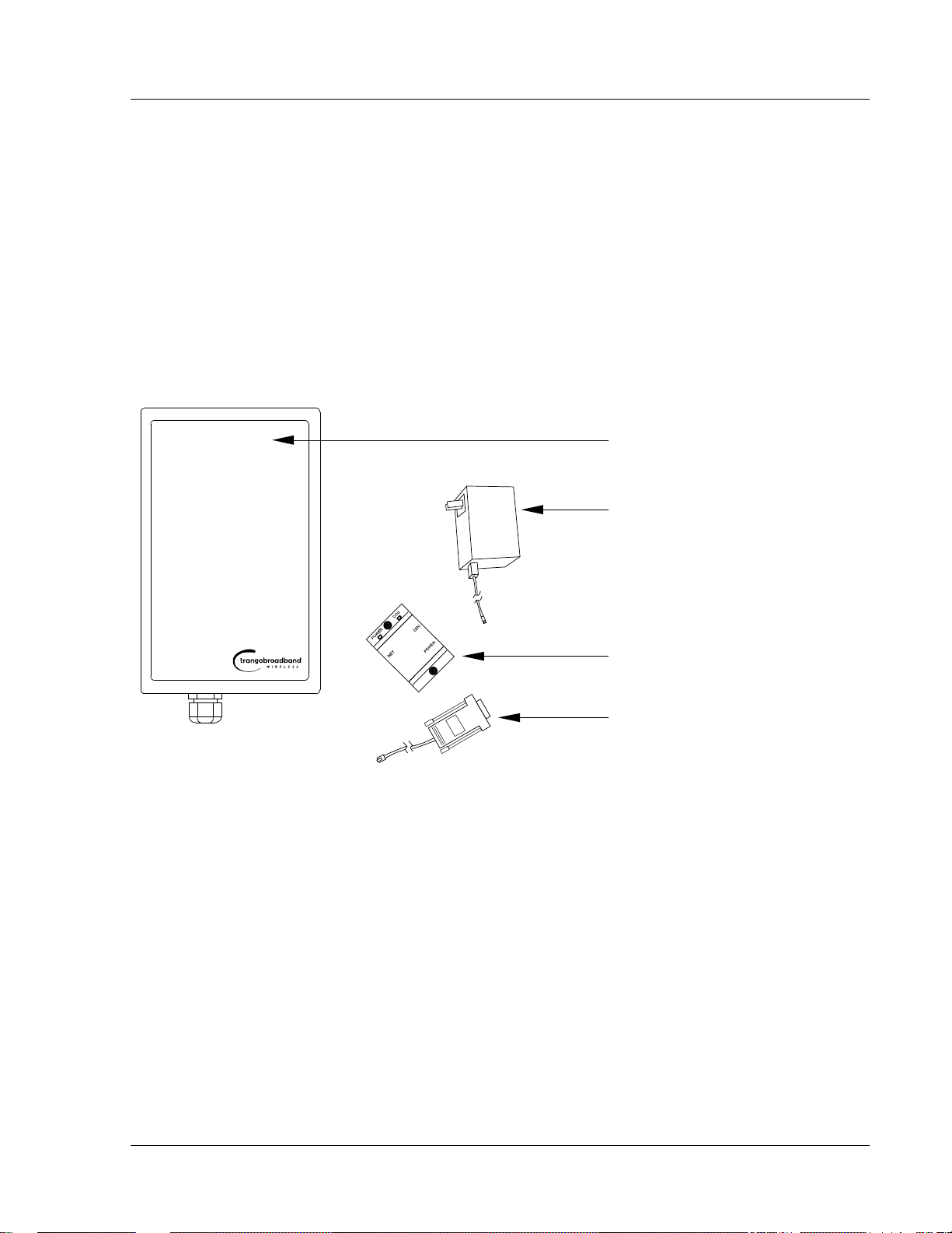
Figure -2-1 Basic Components of an M900S Radio
Radio (AP or SU) antenna
Power Supply (120 VAC-20 VDC)
J Box (Power over Ethernet Injector)
Serial Programming Cable (AP Only)
Figure 2-2 Bottom of Radio
picture of bottom of radio w/label for Ethernet Port and LED
cover
At the bottom of the M900S are two access ports: a twist-on weatherproof cable port for RJ-45 Ethernet (and PoE), and a translucent
access cover plug over the unit’s diagnostic LEDs and reset button. The LEDs will be discussed later in this text.
The radio’s model number and FCC ID, MAC ID, and Serial # are located on the side of the radio.
Trango Broadband Wireless — User Manual Access5830 Rev. D
Page 3
Getting Started
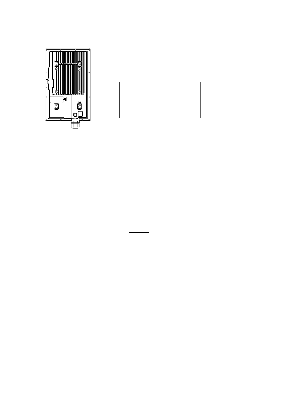
Figure 2-3 Back of Radio
Trango Broadband Wireless
M9000S-AP Rev. A
S/N: 00000XXXX
MAC: 00 01 DE 00 02 F3
FCC ID: NCYM900SAP
Canada: XXXXXXXXXX
This equipment has been tested and found to comply with the limits for a Class B digital device,
pursuant to Part 15 of the FCC Rules. These limits are
Figure 2-4 Side of Radio & Location of Reverse Polarity SMA Connector
Insert picture of side of radio showing rev. polarity SMA Connector
Section 3 Getting Started
This section explains how to power your radios, establish TCP/IP connectivity to the radios, as well as how to access the HTTP
browser and the command line interfaces.
Connections and Power
Connection and powering of radios is the same for APs and SUs.
?? Connect a Cat-5 (straight through) Ethernet cable (we recommend shielded twisted pair) between the ODU (out door unit)
port of the J-box and the RJ-45 connector on the radio. Note that this cable will carry power over Ethernet (PoE).
?? If connecting to a COMPUTER, use a Cross-Over Ethernet cable from the NET port of the J-box to the computer’s Ethernet
port.
If connecting to a HUB, SWITCH, or ROUTER, use a Straight-Thru cable.
?? Plug the AC adapter into an AC outlet.
Trango Broadband Wireless — User Manual Access5830 Rev. D
Page 4
Getting Started
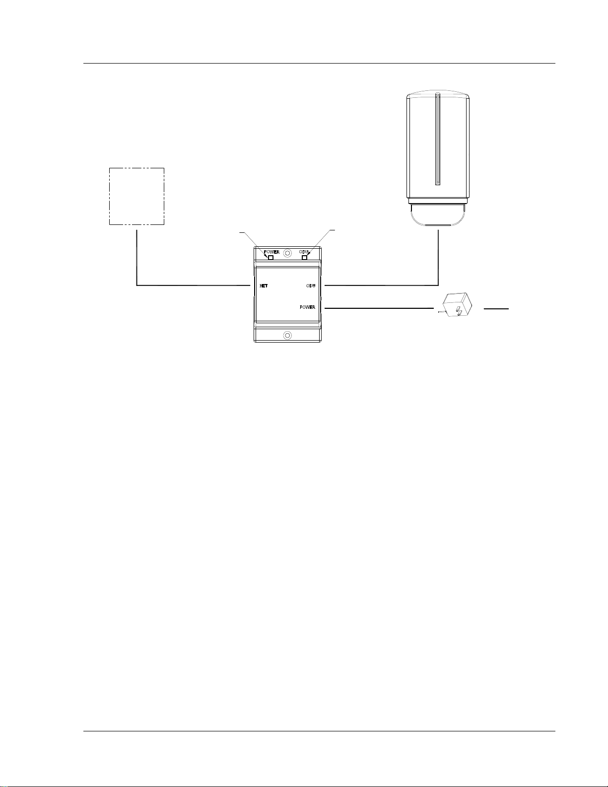
Figure 3-1 Wiring Diagram
NETWORK
OR
COMPUTER
INDICATES POWER TO J BOX
CAT-5
USE STRAIGHT-THRU CABLE
IF TO HUB, SWITCH OR ROUTER
USE CROSS-OVER CABLE IF TO COMPUTER
POWER OVER ETHERNET
J BOX
INDICATES POWER TO RADIO
CAT-5
STRAIGHT-THRU CABLE
20 VOLT POWER
SUPPLY
AC POWER
Both green LEDs on the J-box should be lit, indicating power is present at the J-box as well as the radio.
You are now ready to configure the radio via the Ethernet port.
Opmode and Radio Management Concepts
Proper connections to the radios and careful IP/routing & planning will enable the network administrator to access and manage the
radios remotely over the network.
Radio management over TCP/IP can be performed from PCs connected to the Ethernet side of each radio. Further, PCs connected to
the AP can manage the SU over their wireless connection; and, PCs connected to the SU can manage the AP, provided that switch 7
(TCP/IP for SU) is enabled at the AP. Switches will be covered later in this text.
Opmode
To fully understand radio management for the Access5830 system, it is important to be familiar with the concept of operation mode or
“opmode”.
APs can be in one of two opmodes; “OFF” opmode, or “AP” opmode. When in “OFF” opmode, the radio is not transmitting, and it is
not attempting to associate with SUs. Alternatively, when in “AP” opmode, the radio is transmitting, and is attempting to associate with
SUs. Similarly, SUs have two opmodes: “SU” opmode or “OFF” opmode.
Certain functions, such as the site survey function and the SU RSSI function can only be performed while the radio is in opmode
“OFF”. See Appendix D – Command Set Reference for a complete listing of commands, and the appropriate opmode(s) for each
command.
Switch Settings
M900S firmware includes several “switches” which are used to set certain operational parameters of the radios. Switch settings can
be changed via the HTTP browser interface or the Command Line Interface. For purposes of radio TCP/IP management, the following
three switches are important:
SU Switch 2 - TCP/IP access to SU from AP side of network requires that the SU’s switch 2 (SW 2 – TCP/IP for AP) be “ON”.
Default setting for SW 2 (from factory) is “ON”.
Trango Broadband Wireless — User Manual Access5830 Rev. D
Page 5
Getting Started
AP and SU Switch 5 – In order to utilize the radio’s HTTP Browser interface, switch 5 (SW 5) must be “ON”. Default seting for SW
5 (from factory) is “ON”.
SU Switch 6 - TCP/IP access direct to SU from SU side of network requires that switch 6 (SW 6) be “ON”. Default setting for SW
6 (from factory) is “ON”. If SW 6 is off, TCP/IP access to SU from SU the SU side of the network is possible only if SU’s opmode is
OFF.
AP Switch 5 – TCP/IP access to AP from SU side of network requires that the AP’s switch 7 (SW 7 – TCP/IP for SU) be “ON”.
Default setting for SW 7 (from factory) is “OFF”.
Browser Interface
The HTTP browser interface is a powerful and easy-to-use configuration and management tool. The pages originate from the radio
itself, so no additional software is needed on the managing PC other than a web browser.
The browser interface’s functionality is a subset of the commands available in the command line interface (CLI). To use the browser
interface – the following must be present:
?? An Ethernet connection between a PC and the radio
?? Ethernet PC connection with subnet that is routable to the radio (default IP address=192.168.100.100)
?? A web browser (i.e. Microsoft Internet Explorer)
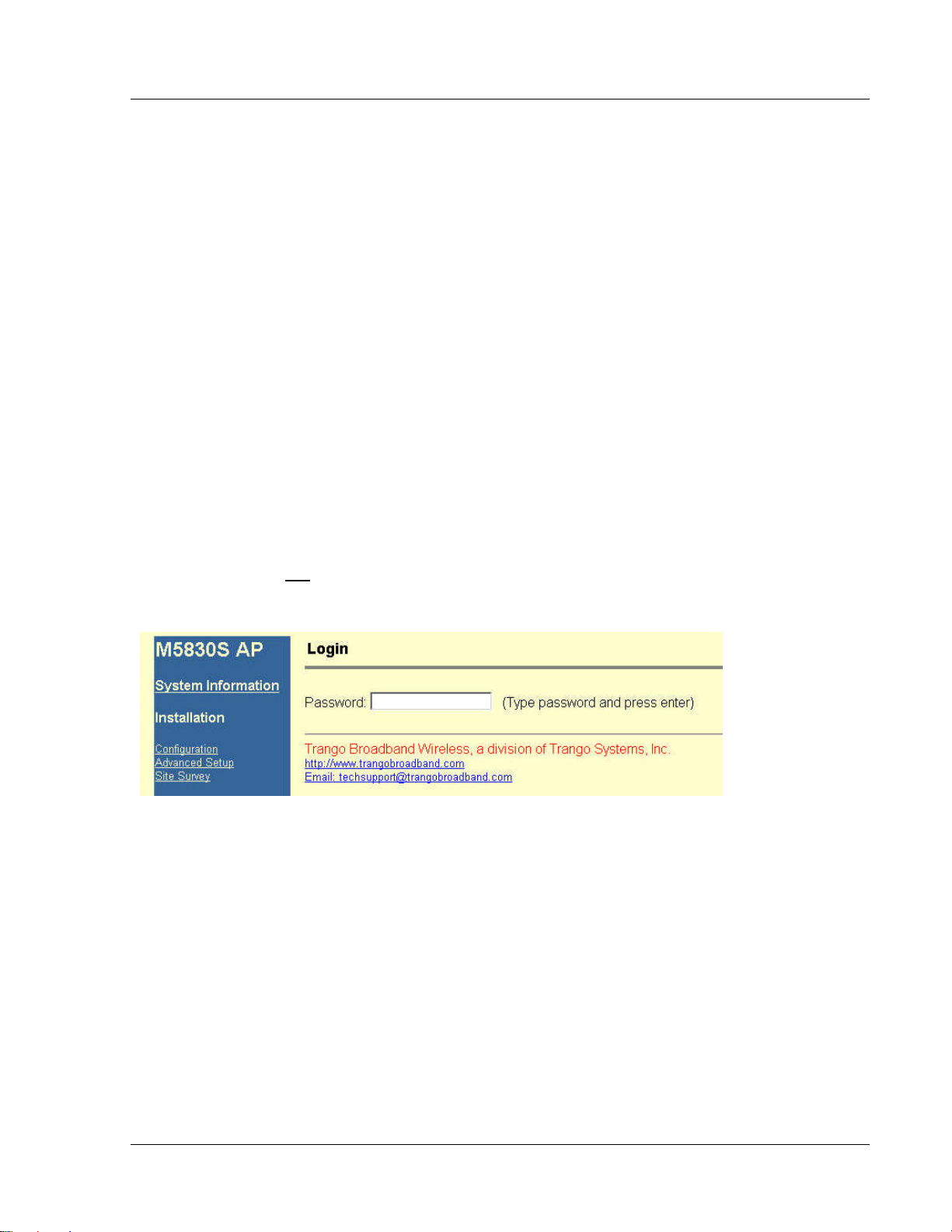
In order to use the browser interface – simply connect the radio to a PC, and type the radio’s IP address into the web browser (i.e.
Microsoft Internet Explorer). This will bring up a logon page.
? Note: Most pages are similar for Access Points and Subscriber Units. When there are significant differences, both are included
in this text. With each page there is a brief description of the major features. For more discussion on any feature see the Command
Set Reference, or click the Help hyperlink.
Figure 3-2 Browser Interface Login Page
Type the password (default trango) and continue. This will bring up the radio’s system information page.
Trango Broadband Wireless — User Manual Access5830 Rev. D
Page 6
Getting Started
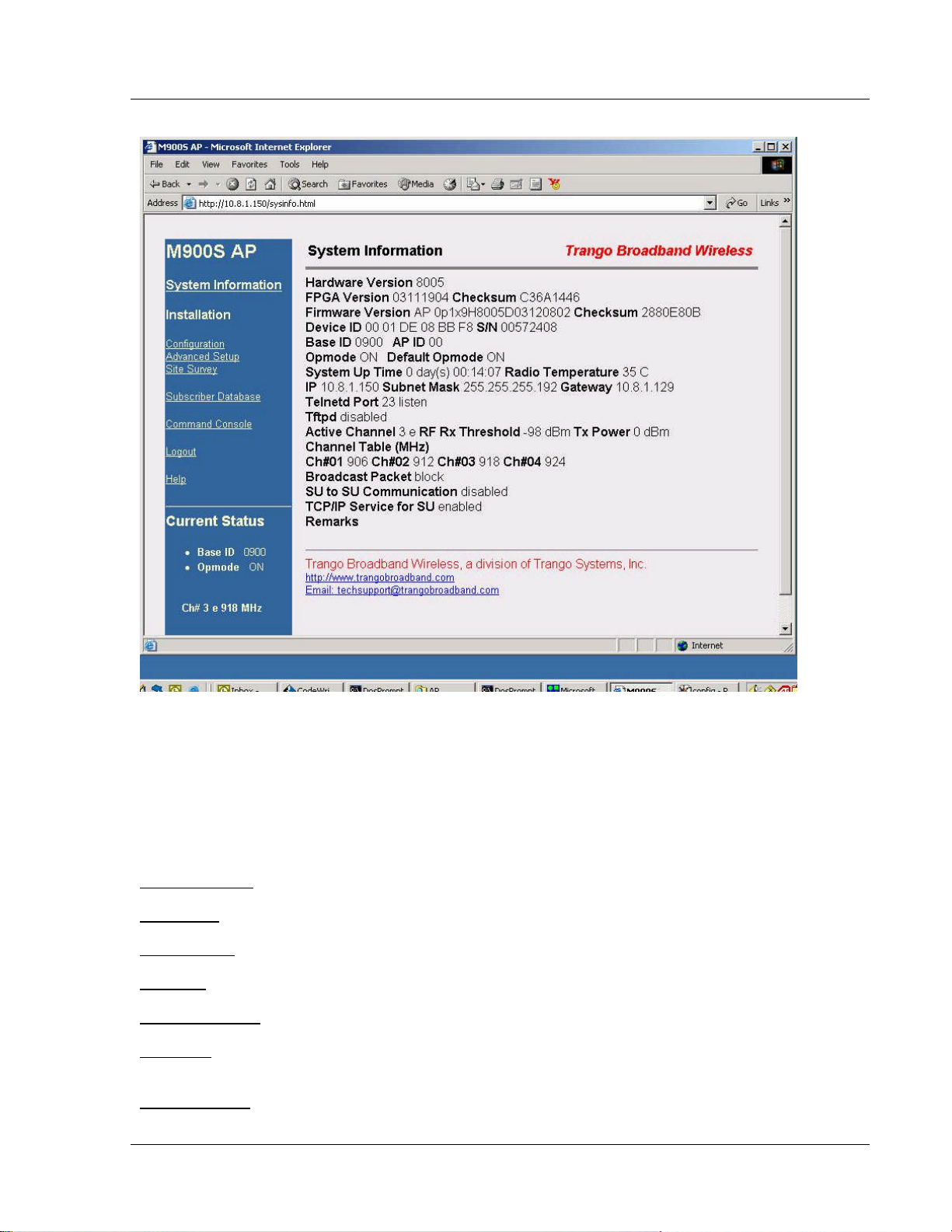
Figure 3-3 Web Browser System Information Page
Figure 2-3 shows system information for an Access Point. Basic system information for a subscriber unit is similar and is covered in
detail later in this text.
The following describes the primary features and pages of the HTTP Browser interface:
Navigation Column: Each page features a navigation column which runs along the left-hand side of the page. The model number of
the radio is listed at the top of the navigation column. On the bottom of the navigation column is the Current Status of the radio
including its Base ID, current Opmode, channel, antenna selection, and frequency.
The navigation column also features links to each of the following pages:
System Information: This page shows most of the basic configuration parameters of the radio. It is the first page shown after login.
Configuration: The essential parameters, such as Base ID, channel and polarization are set here.
Advanced Setup: The advanced RF parameters, such as transmit power are set here.
Site Survey: From here, in Opmode Off, the user can conduct a spectrum analysis.
Subscriber Database: This is the page for defining which SUs can associate to the AP.
Link Control: This page shows which SUs are associated. This page also provides several tools for evaluating the quality of the
wireless link.
Command Console: From this page, the user can run any console command which is not interactive (i.e. ipconfig). The results are
reported back via HTTP screen. For a complete list of console commands, type "help" or “?” in the entry field.
Trango Broadband Wireless — User Manual Access5830 Rev. D
Page 7

Getting Started
Logout: This link will end the current HTTP session with the radio.
Help: The Browser Interface features useful Help pages which explain all listed parameters. To access the help pages click on the
Help link.
For a complete description on use of the Browser Interface, see Appendix A.
Command Line Interface
Although most radio functions can be managed via the browser interface, the command line interface (CLI) does provide slightly more
functionality. The CLI can be accessed through Telnet.
Telnet
Open a command prompt (DOS) session on your PC. Open a Telnet session by typing:
telnet [ip address of radio]
Example:
C:>telnet 192.168.100.100
All Trango radios (AP and SU) come factory pre-configured with a default IP address 192.168.100.100. In Telnet, you will be greeted
with current hardware and firmware information and prompted for a password. Type in the password and press enter. The factory
default password is trango.
To terminate a CLI session (Telnet or Serial) type the command logout.
? Note: Type help, or ? for a listing of all CLI commands. Type help <command> for the syntax of a particular command.
The majority of the CLI commands will be covered throughout this text as well as in Appendix B on the Command Set Reference.
Troubleshooting
If you can not telnet into the radio or open an HTTP browser session, check cable connections, ensure proper use of cross-over vs.
straight-through cable, ensure PC’s subnet is routable to radio’s IP address. If you can still not access the radio’s management
interfaces, consult the troubleshooting guide which is available at www.trangobroadband.com in the Technical Support area of the
website.
Reset Button
M900S APs and SUs feature a reset button (located under the translucent plug which can be pressed with a small object such as a
paper clip. Pressing the reset button will reset all of the radio’s parameters (including IP address and passwords) to factory default
192.168.100.100 and password trango. The reset button can be useful if you forget or are unsure of the radio’s IP address/password.
Trango Broadband Wireless — User Manual Access5830 Rev. D
Page 8

Basic Configuration via Browser Interface
Section 4 Basic Configuration via Browser Interface
This section describes a few more basic concepts and how to establish a basic wireless link between AP and SU, using the Browser
(HTTP) Interface . This section is written to address only the most basic steps in establishing a link in the lab, or a bench-top
environment. It is highly recommended to read the other sections of this manual to gain an understanding of all important
configuration parameters and procedures prior to deploying any wireless equipment.
In this section you will:
?? Learn about AP and SU Basic Configuration Screens and Parameters
?? Populate Access Point’s Subscriber Unit Data Bases (SUDB) with at least one SU.
?? Configure Other Basic AP Parameters
?? Configure Basic SU Parameters
?? Establish a Wireless Link
?? Evaluate Link Quality
The Access5830 uses the concept of “association” to indicate that the APs and SUs are communicating. If all parameters are properly
set, the AP will begin actively searching for the SUs in its SU database (SUDB). Once an active SU is detected, the authentication and
association process will begin.
Essentials to Establish a Wireless Link with M900S Series Radios
?? Base ID in AP and SU must match
?? MAC Address of SU must match an entry in the subscriber unit database (SUDB)
?? AP must be in Opmode “AP”
?? SU must be in Opmode “SU”
?? Adequate signal strength must be received at each radio
If all of these parameters are met, and if the AP and SU are within range - and properly aligned, the wireless link will automatically
establish itself and Ethernet traffic will begin to pass between the radios.
? Note: This section utilizes the Browser Interface as the configuration tool. For the equivalent CLI commands, see Section 5.
Configuring AP Subscriber Unit Database
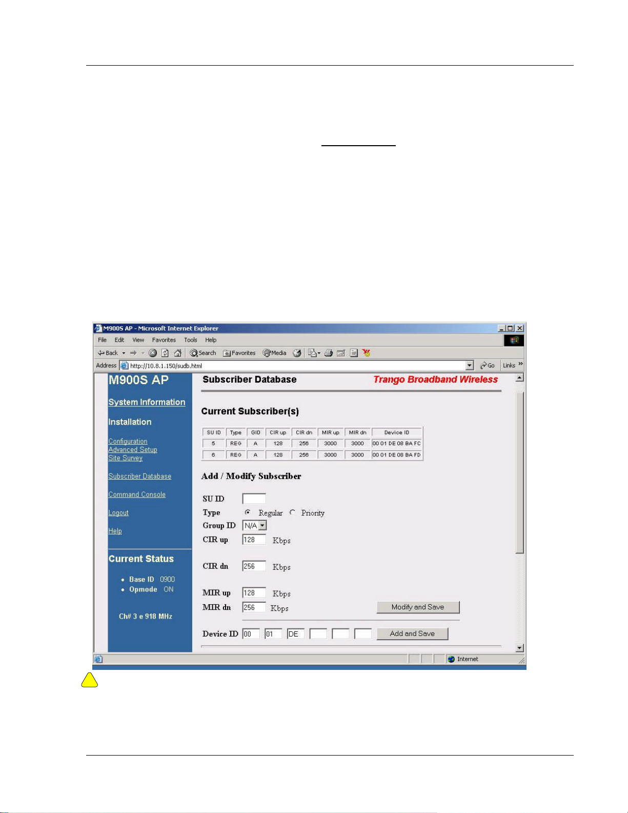
Prior to establishing a wireless link, the user must configure the Subscriber Unit Database (SUDB) in the AP with each SU’s MAC
address and related settings. The subscriber unit database includes detailed information about each SU. The user uses the
Subscriber Database page to add, modify, and delete SUs. The key information for each SU includes the following:
SU ID: User Definable subscriber unit ID (1…8190)
TYPE: PR Priority or REG Regular. Priority SUs are favored in the dynamic polling process and thus respond with
less latency than regular SUs.
Group: SU to SU Group # (1..F in hex) for SU to SU communications. Only SUs with same SU to SU group # may
communicate with each another.
CIR UP: Committed Information Rate from SU to AP. Minimum upstream rate (measured in Kbps) at which the SU will
attempt to deliver bandwidth to the AP. Maximum setting is 3000.
CIR DOWN: Committed Information Rate from AP to SU. Minimum rate (measured in Kbps) at which the AP will attempt to
deliver bandwidth to this SU. Maximum setting is 3000.
MIR UP: Maximum Information Rate from SU to AP. Maximum upstream rate (measured in Kbps) at which the SU will
attempt to deliver bandwidth to the AP. Maximum setting is 3000.
MIR UP: Maximum Information Rate from AP to SU. Maximum rate (measured in Kbps) at which the AP will attempt to
deliver bandwidth to this SU. Maximum setting is 3000.
DEVICE ID: MAC address of the SU. The MAC address and BASE ID are the basis for authentication with the AP.
Trango Broadband Wireless — User Manual Access5830 Rev. D
Page 9
Basic Configuration via Browser Interface
. To set up an SU in the SU Database, complete the following steps:
1. Connect to the AP (see Getting Started) and open the Subscriber Database page.
2. Enter SU ID
3. Select: either PRIORITY or REGULAR.
4. If SU will be part of an SU to SU group, enter the SU to SU group number.
5. CIR up: (SU to AP Committed Information Rate) – minimum upstream bandwidth for the SU in Kbps.
6. CIR dn: (AP to SU Committed Information Rate) – minimum downstream bandwidth for the SU in Kbps.
7. MIR up: (SU to AP Maximum Information Rate) – maximum upstream bandwidth for the SU in Kbps.
8. MIR dn: (AP to SU Maximum Information Rate) – maximum downstream bandwidth for the SU in Kbps.
9. Device ID is the MAC Address of the SU
10. Save and Activate changes
Important! Always remember to Save and Activate changes, or the SUDB will revert back to its previous state after power cycle or
!
reboot.
Trango Broadband Wireless — User Manual Access5830 Rev. D
Page 10
 Loading...