

Page 1
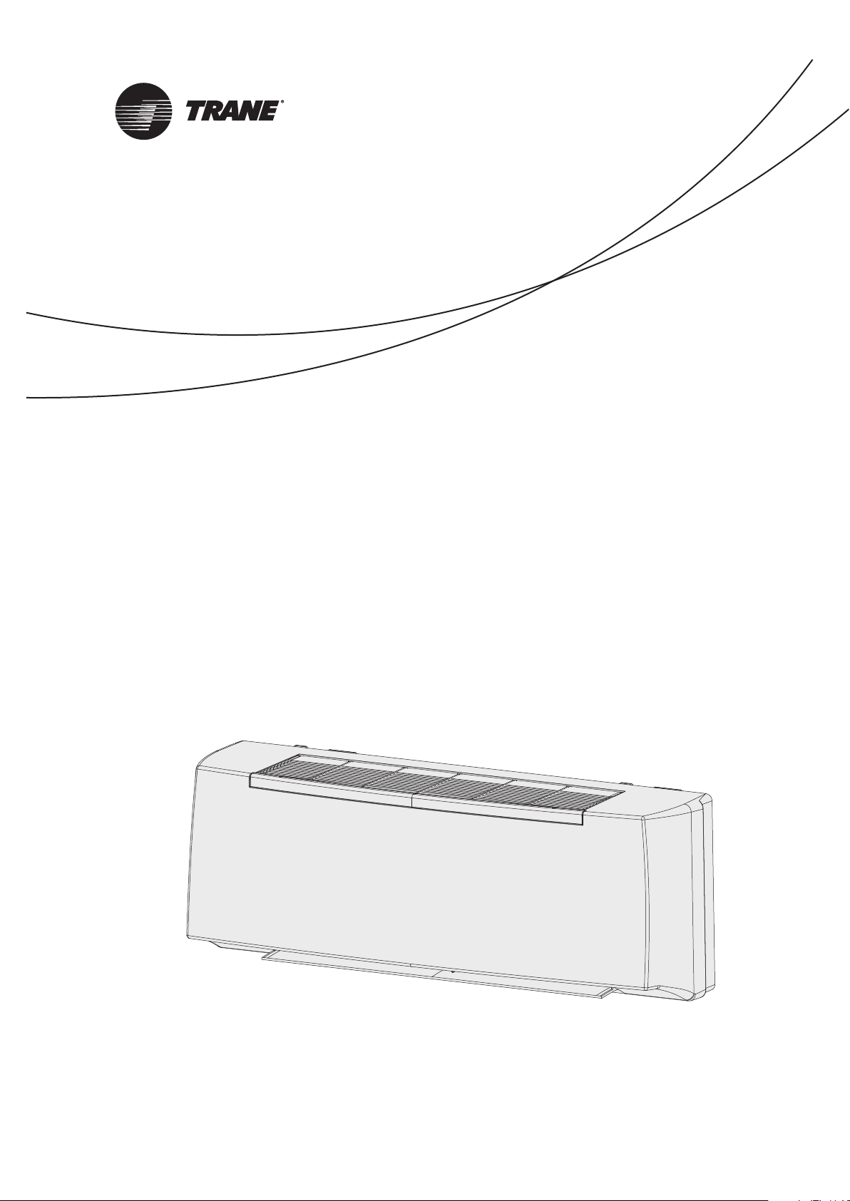
Technical guide
WFS 1 / WFS 2 / WFS 3 / WFS 4
Fan coil units
Ventilo-convecteurs
Gebläse-Konvektoren
Ventiladores convectores
Ventilconvettori
Ventilators-convectors
September 2016
UNT-SVX036A-XX
Page 2
INDICE
INDEX
Regole
fondamentali di sicurezza
Utilizzo e
conservazione del manuale
Scopo
Identificazione macchina
Trasporto
Pesi e
dimensioni unità imballata
Note generali alla consegna
Avvertenze generali
Prescrizioni di sicurezza
Limiti di impiego
Smaltimento
Caratteristiche tecniche
Scelta
della posizione dell’unità
Installazione meccanica
Collegamento idraulico
Collegamenti elettrici
Comandi e schemi elettrici
Legenda
Resistenza elettrica EH
Pulizia,
manutenzione, ricambi
Ricerca guasti
Perdite di carico lato acqua
3
Fundamental safety rules
Use and
9
preservation of the manual
10
Application
11
Identifying the appliance
12
Transport
Weights and
12
dimension packed unit
13
General notes on delivery
13
General warnings
14
Safety rules
15
Operating limits
15
Waste disposal
16
Technical characteristics
Selection
17
of position of the unit
19
Mechanical installation
20
Hydraulic connections
24
Electrical connections
Electrical controls
25
and wiring diagrams
25
Legend
29
EH Electrical heater
Cleaning, maintenance
34
and spare parts
35
Troubleshooting
36
Pressure drop table
4
9
10
11
12
12
13
13
14
15
15
16
17
19
20
24
25
25
29
34
35
36
2
UNT-SVX036A-XX
Page 3

TABLE DES MATIÈRES INHALT ÍNDICE INHOUD
Règles
fondamentales de sécurité
Utilisation et
conservation du manuel
But
Identification des machines
Transport
Poids et dimensions
de l’unité emballée
Remarques générales
pour la livraison
Généralités
Consignes de securité
Limites d’emploi
Élimination
Caractéristiques techniques
Choix
de la position de l’unite
Installation mécanique
Raccordement hydraulique
Branchements électriques
Commandes
et schémas électriques
Légende
Batterie électrique EH
Nettoyage, entretien
et pièces de rechange
Dépannage
Pertes de charge côté eau
Grundlegende
Sicherheitsvorschriften
5
Verwendung und
9
Aufbewahrung des Handbuchs
10
Zweckbestimmung
11
Kennzeichnung des Gerätes
12
Transport
Gewicht und Dimensionen
12
verpacktes Gerät
Allgemeine Hinweise
13
zur Lieferung
13
Allgemeine Hinweise
14
Sicherheitsvorschriften
15
Betriebsgrenzen
15
Entsorgung
16
Technische Merkmale
17
Positionierung der Einheit
19
Mechanische Installation
20
Wasseranschluss
24
Elektroanschlüsse
25
Steuerungen und Schaltpläne
25
Legende
29
Elektroheizregister EH
Reinigung,
34
Wartung, Ersatzteile
35
Fehlersuche
36
Wasserseitige Druckverluste
Reglas
fundamentales de seguridad
6
Uso y
conservación del manual
9
Objetivo
10
Identificación máquina
11
Transporte
12
Peso y
dimensión unidad embalado
12
Notas generales
para la entrega
13
Advertencias generales
13
Prescripciones de seguridad
14
Límites de uso
15
Eliminación
15
Características técnicas
16
Elección
de la posición de la unidad
17
Instalación mecánica
19
Conexión hidráulica
20
Conexiones eléctricas
24
Mandos y
esquemas eléctricos
25
Leyenda
25
Batería eléctrica EH
29
Limpieza,
mantenimiento, repuestos
34
Búsqueda de averías
35
Pérdidas de carga lado agua
36
Belangrijke
veiligheidsvoorschriften
7
De handleiding
gebruiken en bewaren
9
Doel
10
Identificatie apparaat
11
Trasporto
12
Gewicht en afmetingen
verpakte eenheid
12
Algemene opmerkingen
bij de levering
13
Algemene voorschriften
13
Veiligheidsvoorschriften
14
Gebruikslimieten
15
Afdanking
15
Technische karakteristieken
16
Positioneringseenheid
17
Mechanische installatie
19
Hydraulische aansluiting
20
Elektrische aansluitingen
24
Bedieningen
en schakelschema’s
25
Legende
25
Elektrische batterji EH
29
Schoonmaak,
onderhoud, wisselstukken
34
Opsporen defecten
35
Waterlekken
36
8
9
10
11
12
12
13
13
14
15
15
16
17
19
20
24
25
25
29
34
35
36
UNT-SVX036A-XX 2A
Page 4

Prima della messa in funzione,
leggere attentamente il manuale di istruzioni.
Attenzione!
Operazioni particolarmente importanti e/o pericolose.
Interventi che possono essere svolti a cura dell’utente.
Interventi che devono essere svolti esclusivamente
da un installatore o un tecnico autorizzato.
REGOLE FONDAMENTALI DI SICUREZZA
È vietato l’utilizzo dell’apparecchio da parte di bambini o di persone
inabili e senza assistenza.
Questo apparecchio è destinato ad essere utilizzato da utilizzatori
esperti o addestrati nei negozi, nell’industria leggera e nelle fattorie,
oppure per uso commerciale da parte di persone non esperte.
È pericoloso toccare l’apparecchio avendo parti del corpo bagnate
ed i piedi nudi.
Non manomettere o modificare i dispositivi di regolazione o sicurezza senza essere autorizzati e senza indicazioni.
Non torcere, staccare o tirare i cavi elettrici che fuoriescono dall’apparecchio anche se lo stesso non è collegato all’alimentazione elettrica.
Non gettare o spruzzare acqua sull’apparecchio.
Non introdurre assolutamente niente attraverso le griglie di aspirazione e mandata aria.
Non rimuovere nessun elemento di protezione senza aver prima
scollegato l’apparecchio dall’alimentazione elettrica.
Non gettare o lasciare il materiale residuo dell’imballo alla portata
dei bambini perché potenziale causa di pericolo.
Non installare in atmosfera esplosiva o corrosiva, in luoghi umidi,
all’aperto o in ambienti con molta polvere.
3
UNT-SVX036A-XX
Page 5
L’apparecchio può essere utilizzato da bambini di età non inferiore a
8 anni e da persone con ridotte capacità fisiche, sensoriali o mentali,
o prive di esperienza o della necessaria conoscenza, purché sotto
sorveglianza oppure dopo che le stesse abbiano ricevuto istruzioni
relative all’uso sicuro dell’apparecchio e alla comprensione dei pericoli ad esso inerenti.
I bambini non devono giocare con l’apparecchio.
La pulizia e la manutenzione destinata ad essere effettuata dall’utilizzatore non deve essere effettuata da bambini senza sorveglianza.
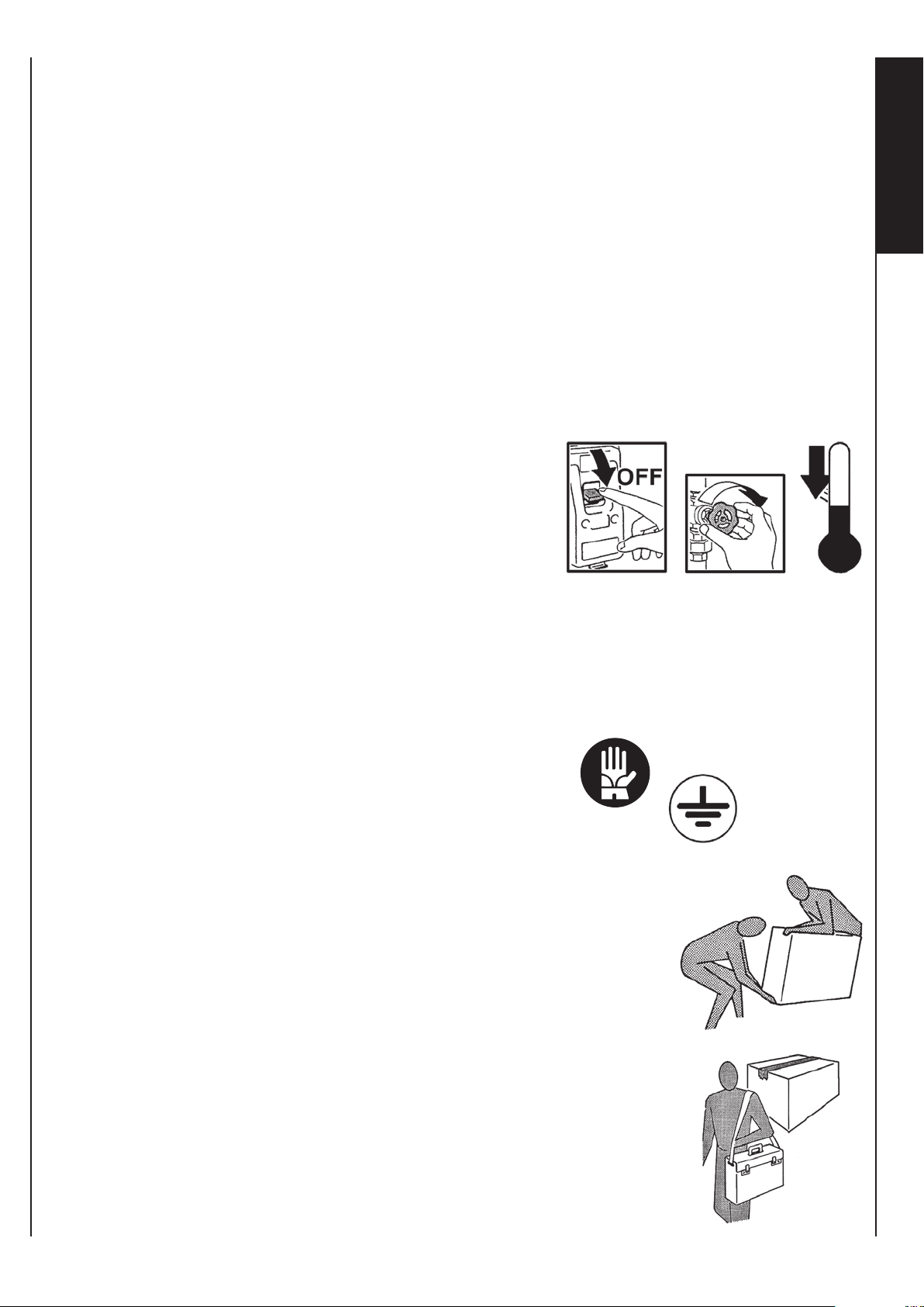
Prima di effettuare qualsiasi intervento assicuratevi che:
1 - L’apparecchio non sia sotto tensione elettrica.
2 - Chiudere la valvola di alimentazione
dell’acqua della batteria e lasciarla
raffreddare.
3 - Installare in prossimità dell’apparec chio o degli apparecchi in posizione
I
T
facilmente accessibile un interruttore di sicurezza che tolga cor rente alla macchina.
Durante l’installazione, la manutenzione e la riparazione, per motivi
di sicurezza, è necessario attenersi a quanto segue:
• Utilizzare sempre guanti da lavoro.
• Non esporre a gas infiammabili.
• Non posizionare sulle griglie oggetti.
Assicurarsi di collegare la messa a terra.
Per trasportare la macchina sollevarla da soli (per
pesi inferiori a 30 Kg) o con l’aiuto di un’altra persona. Sollevarla lentamente, facendo attenzione
che non cada.
Non inserire oggetti nell’elettroventilatore nè tantomeno le mani.
Non togliere le etichette di sicurezza all’interno dell’apparecchio.
In caso di illeggibilità richiederne la sostituzione.
In caso di sostituzione di componenti richiedere
sempre ricambi originali.
UNT-SVX036A-XX
3A
Page 6
Carefully read the following user information manual
before starting up the machine.
Warning!
Particularly important and/or delicate operations.
Operations which may be carried out by the user.
Interventions to be carried out exclusively
by an installer or authorized technician.
FUNDAMENTAL SAFETY RULES
The unit must never be used by children or unfit persons without
supervision.
This appliance is intended to be used by expert or trained users in
shops, in light industry and on farms, or for commercial use by lay
persons.
It is dangerous to touch the unit with damp parts of the body and
bare feet.
Never tamper or modify regulation and safety devices without prior
authorisation and instructions.
Never twist, detach or pull power cables, even when the unit is
unplugged from the mains power supply.
Neither throw nor spray water on the unit.
Never introduce foreign objects through the air intake and discharge
grids.
Never remove protective elements without first unplugging the unit
from the mains power supply.
Do not throw packaging material away or leave it with in reach of
children as it may represent a hazard.
Do not install in explosive, corrosive or damp environments, outdoors
or in very dusty rooms.
UNT-SVX036A-XX4
Page 7

This appliance can be used by children aged from 8 years and above
and persons with reduced physical, sensory or mental capabilities or
lack of experience and knowledge if they have been given supervision
or instruction concerning use of the appliance in a safe way and
understand the hazards involved.
Children shall not play with the appliance.
Cleaning and user maintenance shall not be made by children without
supervision.
Before carrying out any operation on the appliance, make sure:
1 - The unit is disconnected from the electrical power supply.
2 - The coil water supply valve is closed
and the coil has cooled down.
3 -
Install a safety switch to turn off current
to the appliance in an easily accessible
position near the unit or units.
During installation, maintenance and repairs, for safety reasons,
observe the following precautions:
• Always use work gloves.
• Do not expose to inflammable gas.
• Do not place objects over the grids.
Make sure the unit is earthed.
U
K
When moving the appliance, lift it by yourself (for
weights of under 30 kg) or with the help of another
person.
Lift it slowly, taking care not to drop it.
Never introduce objects or the hand into the fans.
Do not remove the safety labels inside the appliance.
If you cannot read the labels, ask for replacements.
Always use original spare parts.
UNT-SVX036A-XX 4A
Page 8

Avant la mise en service,
lire attentivement le manuel d’instructions.
Attention ! Opérations
particulièrement importantes et/ou dangereuses.
Interventions pouvant être effectuées par l’utilisateur.
Interventions à effectuer uniquement
par un installateur ou un technicien autorisé.
RÈGLES FONDAMENTALES DE SÉCURITÉ
Il est interdit d’utiliser l’appareil aux enfants et aux personnes inaptes
et sans assistance.
Cet appareil est destiné à être utilisé par des utilisateurs experts
ou formés dans les magasins, l’industrie légère et les exploitations
agricoles, ou à un usage commercial par des personnes non expertes.
Il est dangereux de toucher l’appareil en ayant des parties du corps
mouillées et les pieds nus.
Ne pas altérer ou modifier les dispositifs de réglage ou de sécurité
sans y être autorisé et sans indications.
Ne pas tordre, détacher ou tirer les câbles électriques qui sortent de
l’appareil, même lorsque celui-ci n’est pas branché à l’alimentation électrique.
Ne pas éclabousser l’appareil ni pulvériser de l’eau dessus.
Ne jamais introduire rien à travers les grilles d’aspiration et de refoulement de l’air.
N’enlever aucun élément de protection sans avoir préalablement
débranché l’appareil de l’alimentation électrique.
Ne pas jeter ou laisser le matériel résiduel de l’emballage à la portée
des enfants car il représente une source potentielle de danger.
Ne pas installer l’appareil dans une atmosphère explosive ou corrosive,
dans des endroits humides, à l’extérieur ou dans des environnements
particulièrement poussiéreux.
UNT-SVX036A-XX5
Page 9
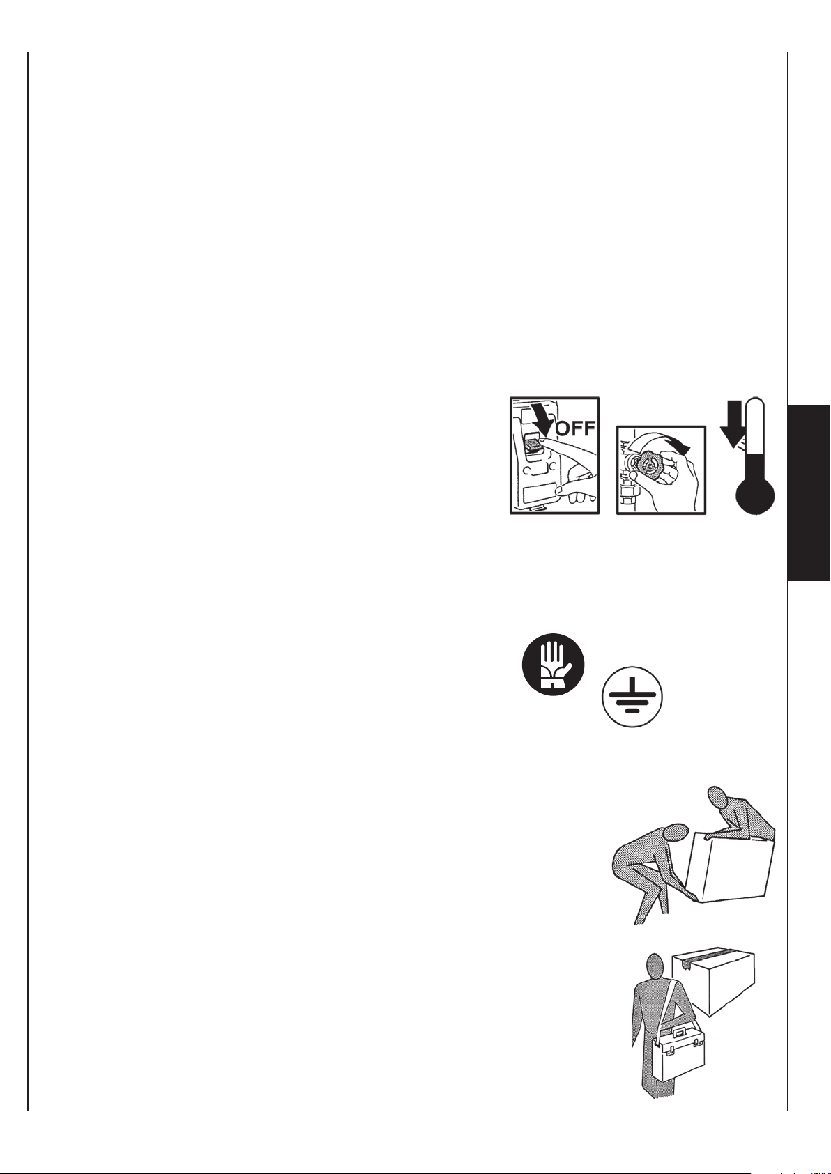
L’appareil peut être utilisé par les enfants âgés de plus de 8 ans et par
les personnes avec des capacités physiques, sensorielles ou mentales
réduites ou qui ne possèdent pas l’expérience ou les connaissances
nécessaires, à condition qu’ils soient surveillés ou qu’ils aient
préalablement reçu des instructions relatives à l’utilisation sûre de
l’appareil et à la compréhension des dangers qui y sont liés.
Les enfants ne doivent pas jouer avec l’appareil.
Le nettoyage et l’entretien qui incombent à l’utilisateur ne doivent
pas être effectués par des enfants sans surveillance.
Avant d’effectuer toute intervention, s’assurer que :
1 - L’appareil ne soit pas sous tension électrique.
2 -
Fermer la vanne d’alimentation de l’eau
de la batterie et la laisser refroidir.
3 - Installer un interrupteur de sécurité
qui coupe le courant d’alimentation
F
de la machine près de l’appareil ou
des appareils, dans une position facile d’accès.
Pour des raisons de sécurité, lors de l’installation, de l’entretien et de
la réparation, il est nécessaire de respecter les consignes suivantes :
• Toujours utiliser des gants de travail.
• Ne pas exposer à des gaz inflammables.
• Ne pas placer d’objets sur les grilles.
S’assurer de raccorder la mise à la terre.
Pour transporter l’appareil, le soulever seul (pour
des poids inférieurs à 30 kg) ou avec l’aide d’une
autre personne. Le soulever lentement, en faisant
attention à ne pas le faire tomber.
Ne pas insérer d’objets ni introduire les mains dans
R
le motoventilateur.
Ne pas enlever les étiquettes de sécurité situées
à l’intérieur de l’appareil.
Si elles sont illisibles, demander leur remplacement.
En cas de remplacement de composants, toujours
demander des pièces de rechange origina
UNT-SVX036A-XX 5A
les.
Page 10
Lesen Sie vor der Inbetriebnahme aufmerksam
die Bedienungsanleitung.
Achtung!
Besonders wichtige und / oder gefährliche Arbeitsgänge.
Maßnahmen, die durch den Anwender
vorgenommen werden können.
Eingriffe, die nur von einem Installateur oder von einem
autorisierten Techniker vorgenommen werden dürfen.
GRUNDLEGENDE SICHERHEITSVORSCHRIFTEN
Die Verwendung des Geräts durch Kinder oder behinderte Personen
ist verboten.
Dieses Gerät ist für die Verwendung durch erfahrene oder geschulte
Bediener in Geschäften, der Leichtindustrie und in landwirtschaftlichen
Betrieben oder für die gewerbliche Verwendung durch nicht erfahrene
Personen vorgesehen.
Es ist gefährlich, das Gerät mit nassen Körperteilen oder nackten
Füßen zu berühren.
Die Regel- und Sicherheitsvorrichtungen niemals ohne Genehmigung
und ohne Anweisungen manipulieren oder verändern.
Die aus dem Gerät austretenden Stromkabel niemals verdrillen,
trennen oder ziehen, auch wenn das entsprechende Kabel nicht an
die Stromversorgung angeschlossen ist.
Das Gerät darf nicht mit Wasserspritzern in Berührung kommen.
Niemals irgendwelche Gegenstände durch die Zu- und Abluftgitter einführen.
Vor dem Entfernen von Elementen der Schutzvorrichtungen muss das
Gerät zuvor immer von der Stromversorgung getrennt werden.
Das Verpackungsmaterial niemals in Reichweite von Kindern lassen,
da es eine potentielle Gefahrenquelle darstellt.
Das Gerät nicht in explosionsfähiger oder korrosiver Atmosphäre, an feuchten
Orten, im Freien oder in sehr staubigen Umgebungen installieren.
UNT-SVX036A-XX6
Page 11
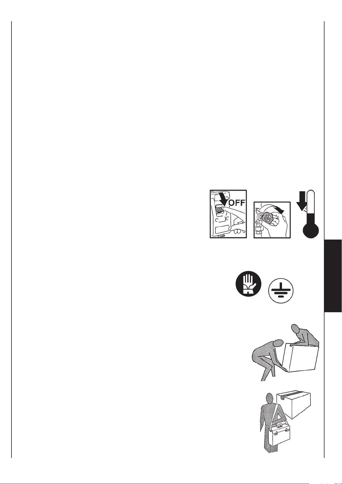
Das Geräte kann von Kindern ab 8 Jahren sowie von Personen mit
reduzierten physischen, sensorischen oder mentalen Fähigkeiten
oder Mangel an Erfahrung und/oder Wissen benutzt werden, wenn
sie beaufsichtigt oder bezüglich des sicheren Gebrauchs des Gerätes
unterwiesen wurden und die daraus resultierenden Gefahren
verstanden haben.
Kinder dürfen nicht mit dem Gerät spielen.
Die Reinigung und die Wartung dürfen nicht durch Kinder durchgeführt
werden, es sei denn, sie sind beaufsichtigt.
Vor der Durchführung von Tätigkeiten muss immer folgendes
sichergestellt werden:
1 - Dass das Gerät nicht unter Spannung steht.
Das Ventil für die Warmwasserzufuhr zum Register schließen und
2 abkühlen lassen.
In der Nähe des Geräts oder der
3 Geräte, in einer gut zugänglichen
Position, einen Sicherheitsschalter
installieren, der eine Trennung der
Maschine vom Stromnetz ermöglicht.
Während Installation, Wartung und Reparatur des Geräts müssen
aus Sicherheitsgründen folgende Anweisungen befolgt werden:
• Immer Arbeitshandschuhe tragen.
• Keinen entflammbaren Gasen aussetzen.
• Keine Gegenstände auf den Gittern abstellen.
Sicherstellen, dass das Gerät an eine Erdung angeschlossen ist.
Für den Transport des Geräts dieses alleine (für
Gewichte unter 30 kg) oder gemeinsam mit einer
anderen Person anheben. Das Gerät langsam
anheben und darauf achten, dass es nicht herunterfällt.
D
E
Keine Gegenstände und vor allem niemals die Hände
in das Elektrogebläse einführen.
Die Sicherheitsetiketten im Inneren des Geräts
dürfen nicht entfernt werden. Sollten sie nicht mehr
lesbar sein, so müssen neue angefordert werden.
Sollte es notwendig sein, Komponenten auszuwechseln,
so müssen immer originale Ersatzteile angefordert
werden.
UNT-SVX036A-XX 6A
Page 12

Antes de la puesta en funcionamiento, hay que leer
atentamente el manual de instrucciones.
Atención!
Operaciones particularmente importantes y/o peligrosas.
Intervenciones que pueden ser realizadas por el usuario.
Intervenciones que tienen que ser efectuadas
sólo por el instalador o el técnico autorizado.
REGLAS FUNDAMENTALES DE SEGURIDAD
Está prohibido que los niños o personas inhábiles y sin asistencia
utilicen el aparato.
Este aparato está destinado para ser utilizado por usuarios expertos
o instruidos en las tiendas, en la industria ligera y en las fábricas, o
para un uso comercial por personas inexpertas.
Es peligroso tocar el aparato si se tiene partes del cuerpo mojadas
y se está descalzo.
No altere o modifique los dispositivos de regulación o seguridad sin
haber sido autorizados y sin indicaciones.
No retuerza, desconecte o tire de los cables eléctricos que sobresalen
del aparato, aunque éste no esté conectado a la alimentación eléctrica.
No vierta o rocíe agua en el aparato.
No introduzca absolutamente nada por las rejillas de aspiración e
impulsión del aire.
No retire ningún elemento de protección sin haber antes desconectado el aparato de la alimentación eléctrica.
No deseche o deje el material residual del embalaje al alcance de
los niños porque es una causa potencial de peligro.
No instale en atmósfera explosiva o corrosiva, en sitios húmedos,
al aire libre o en ambientes con mucho polvo.
UNT-SVX036A-XX7
Page 13
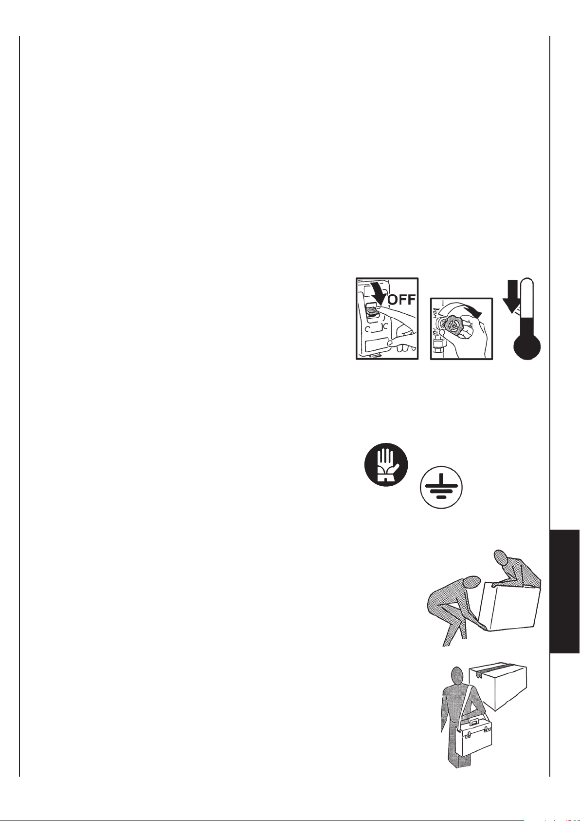
El aparato puede ser utilizado para niños de edad no inferior a 8 años
y para personas con reducidas capacidades físicas, sensoriales o
mentales, o sin experiencia o conocimientos necesarios, siempre que
estén bajo vigilancia o después de que hayan recibido las instrucciones
relativas al uso seguro del aparato y a la comprensión de los peligros
inherentes.
Los niños no deben jugar con el aparato.
La limpieza y el mantenimiento destinados a ser realizados por el
usuario no deben efectuarse por niños sin vigilancia.
Antes de efectuar cualquier intervención, asegúrese de que:
1 - El aparato no esté bajo tensión eléctrica.
2 - Cierre la válvula de alimentación del
agua de la batería y deje que se enfríe.
3 -
Ha instalado en proximidad del aparato o
de los aparatos, en posición fácilmente
accesible, un interruptor de seguridad
que corte la corriente a la máquina.
Durante la instalación, el mantenimiento y la reparación, por motivos
de seguridad, es necesario atenerse a lo siguiente:
• Utilice siempre guantes de trabajo.
• No se exponga a gases inflamables.
• No coloque objetos en las rejillas.
Asegúrese de conectar la puesta a tierra.
Para transportar la máquina, eléverla solo (para
pesos inferiores a 30 kg) o con la ayuda de otra
persona.
Eléverla lentamente, teniendo cuidado de que no
E
S
se caiga.
No introduzca objetos en el ventilador eléctrico, ni
mucho menos las manos.
No quite las etiquetas de seguridad en el interior
del aparato.
En caso de que sean ilegibles, solicite su sustitución.
En caso de sustitución de componentes, solicite
siempre repuestos originales.
UNT-SVX036A-XX 7A
Page 14

Vóór de installatie van het apparaat
neemt u aandachtig deze handleiding door.
Opgelet! Werkzaamheden
bijzonder belangrijken en/of gevaarlijken.
Handelingen die kunnen
uitgevoert te worden door de gebruiker.
Reparaties van het apparaat dienen uitgevoerd te
worden door gespecialiseerd en opgeleid personeel.
BELANGRIJKE VEILIGHEIDSVOORSCHRIFTEN
De ventilatorconvector dient niet te worden gebruikt door kinderen
of onbekwame personen, zonder toezicht.
Dit apparaat is bedoeld om te worden gebruikt door ervaren gebruikers
of formaten in winkels, in de lichte industrie en op boerderijen, of voor
commercieel gebruik door niet-deskundigen.
Het is gevaarlijk het apparaat aan te raken wanneer delen van het
lichaam nat zijn of men op blote voeten loopt.
De regel- of veiligheidsinrichtingen worden niet gehanteerd of gewijzigd
zonder toelating.
De stroomkabels die uit het apparaat steken, worden niet gekneld,
losgekoppeld of onder trekspanning gebracht, zelfs wanneer het
apparaat niet aangesloten is op het elektriciteitsnet.
Zorg ervoor dat het apparaat niet in contact komt met water.
Zorg ervoor dat niets door de aanzuigen luchtinlaatrooster kann dringen.
Verwijder geen enkele beveiliging alvorens het apparaat losgekoppeld
te hebben van het elektriciteitsnet.
Laat het verpakkingsmateriaal niet rondslingeren of binnen het bereik
van kinderen, omdat het gevaarlijk kan zijn.
Stel het apparaat niet op in een explosieve of corrosieve omgeving,
op een vochtige plaats, buiten of in ruimten met veel stof.
8
UNT-SVX036A-XX
Page 15

Het apparaat is niet bestemd voor gebruik door personen (8 jaar oude
kinderen inbegrepen) met beperkte fysieke, sensoriële of mentale
capaciteiten of met onvoldoende ervaring of kennis, tenzij ze
gebruik hebben kunnen maken, dankzij het toedoen van iemand die
verantwoordelijk is voor hun veiligheid, van toezicht of aanwijzingen
over het gebruik van het apparaat.
Kinderen dienen onder toezicht te staan om zich ervan te verzekeren
dat zij niet met het apparaat spelen.
Alvorens u een handeling uitvoert aan het apparaat, vergewis u
ervan dat:
1 - De ventilatorconvector niet onder elektrische spanning staat.
2 - De watertoevoerklep van de batterij
gesloten is.
Laat deze laatste afkoelen.
3 - Installeer vlakbij het apparat of de
apparaten een makkelijk bereikbare
noodschakelaar die de stroomtoevoer naar de machine onderbreekt.
Tijdens de installatie, het onderhoud en de reparaties, is het uit
veiligheidsoverwegingen noodzakelijk na te leven wat volgt:
• Gebruik altijd werkhandschoenen.
• Niet blootstellen aan brandbare gassen.
• Geen voorwerpen op de roosters plaatsen.
Zorg voor een aardaansluiting.
Voor het transport, heft u de machine alleen (voor
gewichten kleiner dan 30kg) of met de hulp van
iemand anders. Hef de machine traag op, zonder
te laten vallen.
Steek geen voorwerpen of handen in de elektronventilator.
Verwijder de veiligheidslabels aan de binnenkant
van het apparaat niet.
Als de labels niet leesbaar zijn, laat u ze vervangen.
Bij de vervanging van onderdelen, vraagt u steeds
naar originele wisselstukken.
UNT-SVX036A-XX
N
L
8A
Page 16
UTILIZZO
E CONSERVAZIONE
DEL MANUALE
USE AND
PRESERVATION
OF THE MANUAL
Il presente manuale di istruzioni è indirizzato all’utente della macchina, al
proprietario al tecnico installatore e
deve essere sempre a disposizione
per qualsiasi eventuale consultazione.
Il manuale è destinato all’utilizzatore,
al manutentore ed all’installatore della
macchina.
Il manuale di istruzioni serve per indicare l’utilizzo della macchina previsto
nelle ipotesi di progetto, le sue caratteristiche tecniche e per fornire indicazioni per l’uso corretto, la pulizia la
regolazione e l’uso; fornisce inoltre
importanti indicazioni per la manutenzione, per eventuali rischi residui e
comunque per lo svolgimento di operazioni da svolgere con particolare
attenzione.
Il presente manuale è da considerare
parte della macchina e deve essere
CONSERVATO PER FUTURI RIFERIMENTI fino allo smantellamento finale della macchina.
Il manuale di istruzioni deve essere
sempre disponibile per la consultazione e conservato in luogo protetto
ed asciutto.
This instruction manual is intended
for the machine’s user, the owner
and installation technician and must
always be available to be consulted,
if necessary.
The manual is addressed to the
maintenance and installation operators
of the machine.
The instruction manual aims to describe
how to use the machine the way the
machine is designed to be used, the
machine’s technical features and to
provide information on how to use the
machine correctly, and how to the clean,
control and operate the machine; in
addition, the manual provides important
information about maintenance, any
residual risks and however how to carry
out operations to be performed with
special care.
This manual is to be considered
a part of the machine and must
be PRESERVED FOR FUTURE
REFERENCE until the machine is
finally dismantled.
The instruction manual must always
be available for consultation and be
preserved in a protected and dry
place.
In caso di smarrimento o danneggiamento, l’utente può richiedere un nuovo
manuale al costruttore o al proprio
rivenditore indicando il modello della
macchina ed il numero di matricola
della stessa visibile sulla targhetta di
identificazione.
Il presente manuale rispecchia lo stato della tecnica al momento della sua
redazione, il fabbricante si riserva il
diritto di aggiornare la produzione ed
i manuali successivi senza l’obbligo
di aggiornarne anche le versioni precedenti.
Il costruttore si ritiene sollevato da eventuali responsabilità in caso di:
- uso improprio o non corretto della
macchina;
-
uso non conforme a quanto espressamente specificato nella presente
pubblicazione;
-
grave carenza nella manutenzione
prevista e consigliata;
- modifiche sulla macchina o qual siasi intervento non autorizzato;
- utilizzo di ricambi non originali o
specifici per il modello;
The user can request a new manual
from the manufacturer or from the
local retailer if the manual is lost or
damaged. The request must include
details of the machine model and
the serial number indicated on the
identifying data plate.
This manual reflects the technical
features at the date of preparation;
the manufacturer reserves the right
to upgrade the production and the
subsequent manuals without being
under an obligation to also update
previous versions.
The manufacturer accepts no liability
in the following cases:
- improper or incorrect use of the
unit;
-
use that does not comply with the
information expressly specified in
this publication;
- serious shortcomings in the fore-
seen and recommended maintenance
operations;
- changes made to the machine or
any unauthorised operation;
- using non-genuine spare parts or
parts not specific to the model;
- inosservanza totale o anche par ziale delle istruzioni;
- eventi eccezionali.
-
total or even partial non-compliance
with the instructions;
- exceptional events.
UNT-SVX036A-XX9
Page 17
UTILISATION
ET CONSERVATION
DU MANUEL
VERWENDUNG UND
AUFBEWAHRUNG
DES HANDBUCHS
USO Y
CONSERVACIÓN
DEL MANUAL
DE HANDLEIDING
GEBRUIKEN
EN BEWAREN
Le présent manuel d’instructions s’adresse
à l’utilisateur de l’appareil, au propriétaire
et au technicien d’installation, et doit
toujours être disponible pour toute
consultation éventuelle.
Le manuel est destiné à l’utilisateur, au
préposé à l’entretien et à l’installateur
de l’appareil.
Le manuel d’instructions sert à indiquer
l’utilisation de l’appareil prévue dans
les hypothèses de conception et ses
caractéristiques techniques, ainsi qu’à
fournir des indications pour son utilisation
correcte, le nettoyage, le réglage et le
fonctionnement ; il fournit également
d’importantes indications concernant
l’entretien, les éventuels risques résiduels
et, de manière générale, les opérations
dont l’exécution exige une attention
particulière.
Le présent manuel doit être considéré
comme une partie intégrante de
l’appareil et doit être CONSERVÉ EN
VUE DE FUTURES CONSULTATIONS
jusqu’à son démantèlement final.
Le manuel d’instructions doit toujours
être disponible pour la consultation
et conservé dans un endroit sec et
protégé.
Das vorliegende Bedienungshandbuch
richtet sich an den Bediener der
Maschine, an den Eigentümer und
an den Installateur und muss jederzeit
zum Nachschlagen griffbereit sein.
Das vorliegende Bedienungshandbuch
richtet sich an den Bediener, den Eigentümer
und den Installateur der Maschine.
Das Bedienungshandbuch dient zu
Angabe der bei der Planung vorgesehenen
Verwendung der Maschine und ihrer
technischen Merkmale sowie zur Lieferung
von Anweisungen für die sachgemäße
Verwendung, die Reinigung, die Justierung
und den Einsatz. Außerdem liefert es
wichtige Hinweise für die Wartung,
eventuelle Restrisiken und ganz allgemein
für Tätigkeiten, die mit besonderer
Vorsicht durchgeführt werden müssen.
Das vorliegende Handbuch ist als Teil
der Maschine zu betrachten und muss
für ZUKÜNFTIGES NACHSCHLAGEN
bis zur endgültigen Demontage der
Maschine aufbewahrt werden.
Das Bedienungshandbuch muss an
einem geschützten und trockenen Ort
aufbewahrt werden und jederzeit zum
Nachschlagen verfügbar sein.
Este manual de instrucciones está
dirigido al usuario de la máquina, al
propietario y al técnico instalador y
debe estar siempre a disposición para
cualquier consulta eventual.
El manual está destinado al usuario,
al encargado del mantenimiento y al
instalador de la máquina.
El manual de instrucciones sirve para
indicar el uso de la máquina previsto
en las hipótesis de diseño, sus características técnicas y para proporcionar
indicaciones para el uso correcto, la
limpieza, la regulación y el uso; también
proporciona indicaciones importantes
para el mantenimiento, para eventuales
riesgos residuales y para la realización
de operaciones que deben desempeñarse con una atención especial.
Este manual debe considerarse como
parte de la máquina y debe CONSERVARSE PARA REFERENCIAS
FUTURAS hasta la eliminación final
de la máquina.
El manual de instrucciones debe estar
siempre a disposición para ser consultado
y debe conservarse en un lugar protegido
y seco.
Deze handleiding met instructies is
gericht tot de gebruiker van de machine,
de eigenaar en de technicus-installateur.
De handleiding moet altijd ter beschikking
zijn om die eventueel te kunnen raadplegen.
De handleiding is bestemd voor de
gebruiker, de onderhoudstechnicus
en de installateur van de machine.
De handleiding met instructies is bedoeld
om het voorziene gebruik van de machine
binnen de ontwerpcondities en de technische
kenmerken ervan aan te geven, en om
aanwijzingen te verstrekken wat betreft het
correcte gebruik, de reiniging en de afstelling.
Bovendien bevat de handleiding belangrijke
aanwijzingen voor het onderhoud en wordt
er op eventuele blijvende risico’s gewezen,
naast aanwijzingen voor het uitvoeren
van handelingen die met bijzondere aandacht
moeten worden uitgevoerd.
Deze handleiding moet als een deel
van de machine worden beschouwd en
dient te worden BEWAARD OM DIE LATER
TE RAADPLEGEN tot aan de uiteindelijke
ontmanteling van de machine.
De handleiding met instructies moet
altijd ter beschikking zijn om die te
raadplegen, en moet op een beschermde,
droge plaats worden bewaard.
En cas de perte ou de détérioration,
l’utilisateur peut demander un nouveau
manuel au fabricant ou à son revendeur,
en indiquant le numéro du modèle et
le numéro de série de l’appareil, indiqué
sur sa plaque d’identification.
Le présent manuel reflète l’état de la
technique au moment de sa rédaction;
le fabricant se réserve le droit de mettre
à jour la production et les manuels suivants
sans obligation de mettre également à
jour les versions précédentes.
Le fabricant décline toute responsabilité
dans les cas suivants :
- utilisation impropre on incorrecte
de l’appareil;
- utilisation non conforme aux
spécifications fournies dans les
présente publication;
- grave carence dans l’entretien
prévu et conseillé;
-
modifications de l’appareil ou toute
autre intervention non autorisée;
- utilisation de pièces de rechange
non originales ou non spécifiques
au modèle;
- non respect total ou partiel des
instructions;
- événements exceptionnels.
Sollte das Handbuch verloren gehen
oder beschädigt werden, so kann der
Bediener beim Hersteller oder einem
Händler ein neues Handbuch anfordern.
Dafür müssen das Modell und Seriennummer der Maschine angegeben
werden, beide befinden sich auf dem
Kennschild an der Maschine.
Das vorliegende Handbuch gibt den Status
der Technik zum Zeitpunkt seiner Erstellung
wieder, der Hersteller behält sich das Recht
vor, die Produktion und die nachfolgenden
Handbücher zu aktualisieren, ohne dass ihm
daraus die Verpflichtung zur Aktualisierung
der vorhergehenden Ausgaben entsteht.
In folgenden Fällen übernimmt der
Hersteller keine Verantwortung:
-
unsachgemäße oder nicht korrekte
Verwendung der Maschine;
- Verwendung, die nicht mit den
ausdrücklich in dem vorliegenden
Dokument angeführten Angaben
übereinstimmt;
-
schwere Mängel bei der vorgesehenen
und empfohlenen Wartung;
-
Änderungen an der Maschine oder
andere nicht genehmigte Eingriffe;
- Verwendung von nicht originalen
oder nicht für das Modell spezifischen
Ersatzteilen;
-
völlige oder teilweise Nichtbeachtung
der Anweisungen;
- außergewöhnliche Ereignisse.
En caso de pérdida o deterioro, el
usuario podrá solicitar un nuevo manual
al fabricante o al revendedor, indicando
el modelo de la máquina y el número
de matrícula de la misma, visible en
la placa de identificación.
Este manual refleja el estado de la
técnica en el momento de su redacción;
el fabricante se reserva el derecho de
actualizar la producción y los manuales
sucesivos sin la obligación de actualizar
también las versiones anteriores.
El fabricante se retiene libre de eventuales responsabilidades en caso de:
- uso indebido o no correcto de la
máquina;
samente especificado en esta
publicación;
- carencias graves en el manteni miento previsto y recomendado;
- modificaciones en la máquina o
- uso de repuestos no originales o
específicos para el modelo;
- incumplimiento total o parcial de
las instrucciones;
- Eventos excepcionales.
uso no conforme con cuanto expre-
cualquier intervención no autorizada;
Indien de handleiding zoek raakt of
beschadigd is, kan de gebruiker bij
de fabrikant of aan de verkoper een
nieuwe handleiding aanvragen, met
vermelding van het model van de
machine en het serienummer, te vinden
op het identificatieplaatje.
Deze handleiding is een weergave van
de staat van de techniek op het moment
van de opmaak ervan. De fabrikant
behoudt zich het recht voor om de
productie en de volgende handleidingen
te updaten zonder dat hij verplicht is om
ook vorige versies te moeten updaten.
De fabrikant acht zich ontheven van
eventuele verantwoordelijkheid in geval van:
-
oneigenlijk of verkeerd gebruik van
de machine;
- gebruik dat niet conform is met
wat uitdrukkelijk in deze uitgave is
aangegeven;
- ernstige nalatigheid tijdens het
voorziene en aanbevolen onderhoud;
-
wijzigingen aan de machine of andere
interventies die niet zijn toegestaan;
- gebruik van niet-originele reserve-
onderdelen of onderdelen die niet
specifiek voor het model zijn;
-
het volledig of gedeeltelijk niet naleven
van de instructies;
- uitzonderlijke gebeurtenissen.
UNT-SVX036A-XX 9A
Page 18
SCOPO
IstruzIonI orIgInalI
APPLICATION
PRIMA DI INSTALLARE
L’APPARECCHIO
LEGGERE ATTENTAMENTE
QUESTO MANUALE
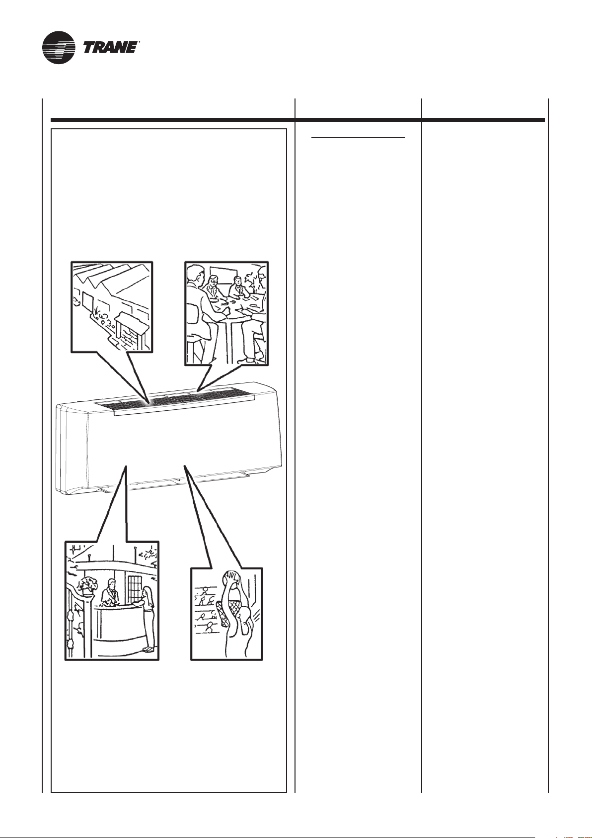
I Ventilconvettori sono stati ideati, progettati e costruiti per riscaldare/raffrescare qualsiasi ambiente civile, industriale, commerciale e sportivo.
L’apparecchio
non può essere impiegato:
• per il trattamento dell’aria
all’aperto
• per l’installazione in ambienti
umidi
• per l’installazione
in atmosfere esplosive
• per l’installazione
in atmosfere corrosive
Verificare che l’ambiente in cui è
installato l’apparecchio non contenga sostanze che generino un
processo di corrosione delle alette
in alluminio.
Gli apparecchi sono alimentati con acqua calda/fredda a seconda che si voglia riscaldare o raffrescare l’ambiente.
Questo apparecchio è destinato ad essere utilizzato da utenti esperti o formati
nei negozi, nell’industria leggera e nelle
aziende agricole, o per uso commerciale da parte di personale non esperto.
CAREFULLY
READ THIS MANUAL
BEFORE INSTALLING
THE APPLIANCE
The fan coils are conceived, designed
and produced to heat/cool all civil,
industrial, commercial or sports
premises.
The appliance
may not be used:
• for outdoor air treatment
• for installation in moist rooms
• for installation
in explosive atmospheres
• for installation
in corrosive atmospheres
Make sure that the environment
where the appliance is installed
does not contain substances
that cause the corrosion of the
aluminium fins.
The appliances are supplied with hot/
cold water depending on whether the
environment is being heated/cooled.
This unit is intended to be used by
expert or trained users in shops, in
light industry and on farms, or for
commercial use by lay persons.
L’apparecchio non è destinato ad essere usato da persone (bambini compresi) le cui capacità fisiche, sensoriali o mentali siano ridotte, oppure con
mancanza di esperienza o di conoscenza, a meno che esse abbiano potuto
beneficiare, attraverso l’intermediazione di una persona responsabile della loro sicurezza, di una sorveglianza
o di istruzioni riguardanti l’uso dell’apparecchio.
I bambini devono essere sorvegliati
per sincerarsi che non giochino con
l’apparecchio.
This unit is not intended for use
by persons (including children) with
reduced physical, sensory or mental
capabilities, or lack of experience and
knowledge, unless they have been given
supervision or instruction concerning
use of the appliance by a person
responsible for their safety.
Children should be supervised to
ensure that they do not play with the
appliance.
10
UNT-SVX036A-XX
Page 19

BUT ZWECKBESTIMMUNG OBJETIVO DOEL
AVANT D’INSTALLER
L’APPAREIL
LIRE ATTENTIVEMENT
CE MANUEL
Les ventilo-convecteurs ont été conçus
et construits pour chauffer/rafraîchir
n’importe quelle ambiance civile,
industrielle, commerciale et sportive.
L’appareil ne peut pas:
• pour le traitement de l’air
en plein air
• être installé dans des locaux
humides
• être installé dans
des atmosphères explosives
• être installé dans
des atmosphères corrosives
Vérifier que la pièce dans laquelle
l’appareil est installé ne contient
pas de substances pouvant engendrer la corrosion des ailettes
en aluminium.
Les appareils sont alimentés avec de
l’eau chaude/froide selon qu’on veut
chauffer ou rafraîchir la pièce.
Cet appareil est destiné à être utilisé par
des utilisateurs expérimentés ou des
formats dans les magasins, chez des
artisans et dans des fermes, ou à des
fins commerciales par des non-experts.
BEVOR DAS GERÄT
INSTALLIERT WIRD, SOLLTE
DIESES HANDBUCH SORGFÄLTIG GELESEN WERDEN
Die Gebläsekonvektoren wurden konzipiert,
entworfen und gebaut, um zivil, industriell,
gewerblich und zu sportlichen Zwecken
genutzte Räume zu heizen bzw. zu kühlen.
Die Geräte darf nicht
eingesetzt werden für:
• die Aufbereitung der Luft
im Freien
• die Installation in feuchten
Räumen
• die Installation
in explosiver Atmosphäre
• die Installation
in korrosiver Atmosphäre
Überprüfen, dass der Raum, in dem
das Gerät installiert wird, keine Stoffe
enthält, die einen Korrosionsprozess
der Aluminiumrippen bewirken.
Je nachdem, ob der Raum beheizt oder
gekühlt werden soll, werden die Geräte
mit warmem, bzw. kalten Wasser gespeist.
Dieses Gerät ist dafür bestimmt, durch
erfahrene Benutzer oder Formate in Geschäften
verwendet werden, in der Leichtindustrie
und auf Bauernhöfen, oder für die kommerzielle
Nutzung von Nicht-Experten.
Los fan coils han sido diseñados, proyectados y construidos para calentar/
refrescar toda clase de ambiente domestico, industrial, comercial y deportivo.
Los aparatos
no se pueden usar para:
• el tratamiento del aire
al aire libre
• su instalación
en locales húmedos
• su instalación
en atmósferas explosivas
• su instalación
en atmósferas corrosivas
Compruebe que la estancia en la
que se está instalado el aparato no
contenga sustancias que generen
un proceso de corrosión de las
aletas de aluminio.
Los aparatos se alimentan con agua
caliente/fría según si se desea calentar o refrescar el local.
Este aparato está diseñado para ser
utilizado por los usuarios o formatos
experimentados en las tiendas, en la
industria ligera y en granjas, o para el
uso comercial por los no expertos.
ANTES DE INSTALAR
EL APARATO
LEA ATENTAMENTE
ESTE MANUAL
VÓÓR DE INSTALLATIE
VAN HET APPARAAT
NEEMT U AANDACHTIG
DEZE HANDLEIDING DOOR
De ventilatorconvectors werden
ontworpen om privé-ruimtes, industriële,
commerciële en sportieve ruimtes te
verwarmen/af te koelen.
De ventilators-convectors
mag niet worden gebruikt:
• voor de zuivering
van de buitenlucht
• voor installatie
in vochtige ruimten
• voorinstallatie in ruimten waar
ontploffingsgevaar heerst
• voor installatie
in corrosieve omgevingen
Controleer of de omgeving waarin
het apparaat geïnstalleerd is geen
stoffen bevat die een roestproces
van de aluminium ribben op gang
brengen.
De apparaten worden gevoed met
warm/koud water, naargelang men de
ruimte wenst af te koelen of te verwarmen.
Dit apparaat is bedoeld om te worden
gebruikt door ervaren gebruikers of
formaten in winkels, in de lichte industrie
en op boerderijen, of voor commercieel
gebruik door niet-deskundigen.
L’appareil n’est pas prévu pour être
utilisé par des personnes (y compris les
enfants) dont les capacités physiques,
sensorielles ou mentales sont réduites,
ou dénuées d’expérience ou de
connaissance, sauf si elles ont pu
bénéficier, par l’intermédiaire d’une
personne responsable de leur sécurité,
d’une surveillance ou d’instructions
préalables concernant l’utilisation de
l’appareil.
Il convient de surveiller les enfants
pour s’assurer qu’ils ne jouent pas
avec l’appareil.
Dieses Gerät ist nicht dafür bestimmt,
durch Personen (einschließlich Kinder),
mit eingeschränkten physischen,
sensorischen oder geistigen Fähigkeiten oder mangels Erfahrung und/
oder mangels Wissen benutzt zu werden,
es sei denn sie werden durch eine für
ihre Sicherheit zuständige Person
beaufsichtigt oder erhielten von ihr
Anweisungen, wie das Gerät zu
benutzen ist.
Kinder sollten beaufsichtigt werden,
um sicherzustellen, dass sie nicht mit
dem Gerät spielen.
Este aparato no debe ser utilizado
por personas (incluidos niños) cuyas
capacidades físicas, sensoriales o
mentales estén disminuidas o que
carezcan de experiencia y conocimientos, al no ser que ellas hayan
podido beneficiar, a través de la intermediación de una persona responsable de su seguridad, de una vigilancia o de instrucciones relativas al
uso del aparato.
Los niños han de vigilarse para asegurarse de que no jueguen con el
aparato.
Het apparaat is niet bestemd voor
gebruik door personen (kinderen
inbegrepen) met beperkte fysieke,
sensoriële of mentale capaciteiten of
met onvoldoende ervaring of kennis,
tenzij ze gebruik hebben kunnen maken,
dankzij het toedoen van iemand die
verantwoordelijk is voor hun veiligheid,
van toezicht of aanwijzingen over het
gebruik van het apparaat.
Kinderen dienen onder toezicht te
staan om zich ervan te verzekeren
dat zij niet met het apparaat spelen.
UNT-SVX036A-XX 10A
Page 20
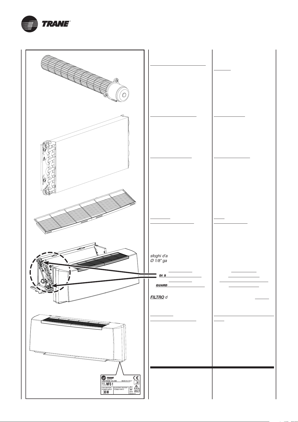
I componenti principali sono:
MANTELLO DI COPERTURA in
materiale sintetico antiurto. È facilmente smontabile per una completa accessibilità dell’apparecchio.
The main components are:
impact-proof synthetic material
CASING.
It can be easily disassembled for
complete access to the appliance.
La griglia di ripresa dell’aria, facente parte del mobiletto, è di tipo ad
alette fisse e posizionato sulla parte superiore.
GRUPPO VENTILATORE
Costituito da ventilatore tangenziale, particolarmente silenziosio
con girante in plastica bilanciata
staticamente e dinamicamente,
direttamente calettata sull’albero
motore.
MOTORE ELETTRICO
Di tipo monofase tensione 230V/50 Hz,
isolamento B e klixon integrato.
La variazione di velocità del ventilatore avviene con l’impiego di autotrasformatore a 6 diverse tensioni
in uscita. Gli apparecchi utilizzano,
come standard, 3 velocità predefinite
con la possibilità, in fase di messa
a punto dell’impianto, di poterle
modificare.
BATTERIA
DI SCAMBIO TERMICO
È costruita con tubi di rame ed
alette in alluminio fissate ai tubi con
procedimento di mandrinatura meccanica. La batteria è dotata di 2 attacchi Ø 1/2” gas femmina. I collettori delle batterie sono corredati di
sfoghi d’aria e di scarichi d’acqua
Ø 1/8” gas.
The air intake grill forming part of
the cabinet, has fixed flaps and is
positioned on the upper part.
FAN ASSEMBLY
Consisting of tangential fan,
particularly silent with statically
and dynamically balanced plastic
propeller, directly tapered onto the
motor shaft.
ELECTRIC MOTOR
Of 230V/50 Hz single-phase voltage,
B insulation and integrated klixon
type.
The fan's speed is changed by using
an auto-transformer with 6 different
output voltages. The appliances
standard use 3 pre-defined speeds
with the possibility of modifying them
during system precision adjustment.
HEAT
EXCHANGE COIL
Made with aluminium finned copper
tubes. The exchanger has two 1/2”
female gas connections. Coil headers
with air vents and water drain outlets
(1/8” dia. gas).
la posIzIone
dI
serIe deglI attacchI
è
a sInIstra,
guardando l’apparecchIo.
FILTRO di materiale sintetico rige-
nerabile.
BACINELLA
RACCOLTA CONDENSA in ma-
teriale plastico, realizzata a forma
di L e fissata alla struttura interna.
IDENTIFICAZIONE
MACCHINA
A bordo di ogni singola macchina
è applicata l’etichetta di identificazione riportante i dati del costruttore ed il tipo di macchina.
(vedi Fig. "A")
as standard,
the connectIons
are
on the left hand sIde
facIng
the unIt.
Regenerable synthetic FILTER.
CONDENSATE COLLECTION
TRAY, plastic, L-shaped, fixed to
internal structure.
IDENTIFYING
THE APPLIANCE
Each unit is supplied with an
identification plate giving details
of the manufacturer and the type
of appliance.
(see Fig. "A")
UNT-SVX036A-XX11
Page 21
Les composants principaux sont:
CARROSSERIE en matériel synthétique antichoc. Il est facilement
démontable pour accéder totalement à l'appareil.
Das Gerät setzt sich hauptsächlich
aus folgenden Bauteilen zusammen:
GEHÄUSE
aus stoßfestem Kunsstoff. Leicht zu
demontieren, um Zugang auf den
Innenteil des Gerätes zu ermöglichen.
Los componentes principales son:
MUEBLE DE COBERTURA en
material sintético antichoque. Se
puede desmontar fácilmente para
acceder completamente al aparato.
De voornaamste onderdelen zijn:
BEHUIZING
synthetisch, schokwerend materiaal.
Gemakkelijk demonteerbaar, zodat
het toestel volledig toegankelijk is.
La grille de reprise d'air, faisant
partie du meuble est de type à
ailettes fixes et placé sur la partie
Das Luftansauggitter ist nicht
verstellbar und ist auf der Oberseite
des Gehäuses angebracht.
supérieure.
GROUPE VENTILATEUR
Constitué d'un ventilateur tangentiel,
particulièrement silencieux avec rotor
en plastique équilibré de manière
statique et dynamique, directement
emboîté sur l'arbre moteur.
MOTEUR ÉLECTRIQUE
De type monophasé, tension 230V/50 Hz,
isolation B et klixon intégré.
La variation de vitesse du ventilateur
s'effectue avec l'utilisation d'un autotransformateur à 6 tensions différentes
en sortie. Les appareils utilisent, comme
standard, 3 vitesses prédéfinies avec
la possibilité, en phase de mise au
point de l'installation, de pouvoir les
GEBLÄSE
Bestehend aus besonders leisem
Tangentialventilator mit statisch
und dynamisch ausgeglichenem
Laufrad aus Kunststoff, das direkt
an der Motorwelle befestigt ist.
ELEKTROMOTOR
Wechselstrom Spannung 230 V/50 Hz,
Isolierung B und eingebautem Klixon.
Die Änderung der Ventilatordrehzahl
erfolgt mithilfe eines Spartransformators
mit 6 unterschiedlichen Ausgangsspannungen. Die Geräte verwenden
serienmäßig 3 festgelegte Drehzahlen,
die bei der Feineinstellung der Anlage
geändert werden können.
modifier.
BATTERIE
D’ÉCHANGE THERMIQUE
Construite avec des tubes en cuivre
et des ailettes en aluminium fixées
aux tubes par dudgeonnage mécanique. La batterie est équipée de
deux raccords Ø 1/2” gaz femelle.
Les collecteurs des batteries sont
dotés de purgeurs d’air et de sorties
d’eau Ø 1/8” gaz.
WÄRMETAUSCHERREGISTER
Bestehend aus Kupferrohren mit
maschinell aufgezogenen Aluminiumlamellen. Die Wärmetauscher sind
mit zwei Anschlüssen mit Innengewinde ø 1/2” Gas versehen. Die
Sammler der Wärmetauscher sind mit
Entlüftungsöffnungen und WasserablassAnschlüssen ø 1/8” Gas versehen.
La rejilla de recuperación del aire,
que forma parte del mueble, es del
tipo con aletas fijas, colocada en
la parte superior.
GRUPO VENTILADOR
Formado por ventilador tangencial,
extremadamente silencioso con
rotor de plástico equilibrado estática
y dinámicamente, directamente
ensamblado al eje motor.
MOTOR ELÉCTRICO
De tipo monofase con tensión de
230V/50 Hz, aislamiento B y klixon
integrado.
La variación de velocidad del ventilador
se realiza usando el auto-transformador
de 6 tensiones de salida diferentes.
Los aparatos, como estándar, utilizan
3 velocidades preconfiguradas con
posibilidad de modificarlas en fase
de puesta a punto de la instalación.
BATERÍA
DE INTERCAMBIO TÉRMICO
Se compone de tubos de cobre y
aletas en aluminio fijadas a los tubos con un procedimiento de mandrilado mecánico. La batería tiene
2 conexiones Ø 1/2” gas hembra.
Los colectores de las baterías tienen
alivios de aire y descargas de agua
Ø 1/8” gas.
Het rooster voor luchtafname, dat
deel uitmaakt van het meubel, is
van het type met vaste vinnen en
bevindt zich aan de bovenkant.
VENTILATORGROEP
Het bestaat uit een tangentiële
ventilator, bijzonder geruisloos, met
statisch en dynamisch uitgebalanceerde
plastic rotor, rechtstreeks verbonden
met de as van de motor.
ELEKTRISCHE MOTOR
Van het type monofase spanning
230V/50 Hz, isolatie B en geïntegreerde
klixon. De snelheidsverandering van de
ventilator gebeurt met behulp van een
spaartransformator met 6 verschillende
spanningen op de uitgang. De toestellen
gebruiken standaard 3 vooraf gedefinieerde
snelheden met de mogelijkheid om die te
wijzigen tijdens de fase waarin het systeem
op punt wordt gesteld.
BATTERIJ
WARMTEWISSELING
Samengesteld uit koperen buizen
en aluminium ribben die met een
mechanisch procédé aan de buizen
bevestigd zijn. De batterij voorzien van
2 vrouwelijke gasaansluitingen van
Ø 1/2” . De collectors van de batterijen
zijn uitgerust met luchtuitlaten en
waterafvoerpijpen van Ø 1/8” gas.
la posItIon
standard
quand on regarde l’appareIl.
des raccords
est
à gauche,
FILTRE en matière synthétique
régénérable.
BAC DE RECUPERATION
DES CONDENSATS, en matière
plastique, réalisé en forme de “L“
befInden
FILTER aus recycelbarem
Synthetikmaterial.
An der Innenstruktur befestigte,
L-förmige KONDENSATWANNE
aus Kunststoff.
et fixé à la structure interne.
IDENTIFICATION
DES MACHINES
Une étiquette d’identification est
appliquée sur chaque machine; elle
indique les données du constructeur
et le type de machine.
KENNZEICHNUNG
DES GERÄTES
Jedes Gerät ist mit einem Typenschild gekennzeichnet, auf dem
die Daten des Herstellers und die
Type des Gerätes angegeben sind.
(voir Fig. "A")
UNT-SVX036A-XX 11A
serIenmässIg
sIch dIe anschlüsse
von
vorne gesehen lInks.
(siehe Abb. "A")
la posIcIón predetermInada
de
las conexIones es
en
la parte IzquIerda mIrando
al
aparato desde enfrente.
FILTRO en material sintético
regenerable.
BARDEJA
DE CONDENSADOS, en material
plástico, con forma de “L” y asegurada a la estructura interna.
IDENTIFICACIÓN
DE LA MÁQUINA
Cada máquina lleva una placa de
identificación en la que figuran los
datos del fabricante y el tipo de
máquina de que se trata.
(véase la Fig. "A")
de serIële posItIe
van
de aansluItIngen Is lInks,
als men vóór het
apparaat
staat.
Herbruikbare FILTER in synthetisch
materiaal.
OPVANGBAK
CONDENSATIEWATER, uitgevoerd
in L-vorm en vastgemaakt aan de
binnenstructuur.
IDENTIFICATIE
APPARAAT
Aan boord van elk apparaat wordt
een identificatielabel aangebracht
met de gegevens van de fabrikant
en het type machine.
(zie Fig. "A")
Page 22
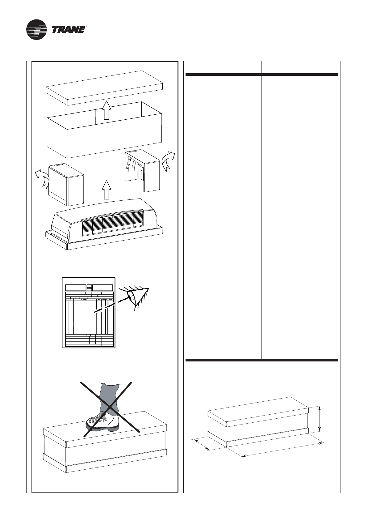
TRASPORTO TRANSPORT
L’apparecchio viene imballato in
scatole di cartone.
Una volta che l’apparecchio è
disinballato controllare che non
vi siano danni e che corrisponda
alla fornitura.
In caso di danni o di sigla dell’apparecchio non corrispondente a
quanto ordinato, rivolgersi al proprio rivenditore citando la serie e
il modello.
The appliance is supplied in cardboard packaging.
After unpacking the appliance, make
sure it is undamaged and corresponds
to the unit requested.
In the event of damage or if the
identification code does not
correspond to that ordered, contact
your dealer immediately, quoting
the series and model.
PESI
E DIMENSIONI
UNITÀ IMBALLATA
395
WEIGHTS
AND DIMENSIONS
PACKED UNIT
270
Z
UNT-SVX036A-XX12
Page 23
TRANSPORT TRANSPORT TRANSPORTE TRANSPORT
L’appareil est emballé dans des
boîtes en carton.
Après avoir déballé l’appareil, contrôler
qu’il n’a subi aucun dommage et
qu’il correspond bien à la fourniture.
En cas de dommages ou si le sigle
de l’appareil ne correspond pas à
ce qui a été commandé, s’adresser
au revendeur en indiquant la série
et le modèle.
Das Gerät wird in Kartons verpackt.
Kontrollieren Sie beim Auspacken
sofort, ob das Gerät unversehrt ist,
und ob es mit den Angaben in den
Versandpapieren übereinstimmt.
Falls Schäden festgestellt werden
sollten, oder wenn die Artikelnummer
nicht mit dem bestellten Gerät übereinstimmt, wenden Sie sich bitte an
Ihren Händler. Geben Sie bei Rückfragen
immer Serie und Gerätemodell an.
El aparato viene embalado en caja
de cartón.
Cuando se desembala el aparato,
es preciso comprobar que no tenga
desperfectos y que se corresponda
con el suministro previsto.
En caso de daños o de sigla del
aparato no correspondiente con la
del pedido, dirigirse al revendedor
indicando la serie y el modelo.
Het apparaat wordt in een kartonnen
doos verpakt.
Eens het apparaat van zijn verpakking
ontdaan, controleert u de integriteit
en conformiteit van het apparaat.
In geval van beschadigingen, of
indien het apparaat niet overeenkomt
met de bestelling, wendt u zich tot
uw verkoper, met vermelding van
het serienummer en het model.
POIDS ET
DIMENSIONS DE
L’UNITE EMBALLEE
mod.
senza valvole – without valves
sans vannes – Ohne ventile
sin válvulas – zonder kleppen
con valvole – with valves
avec vannes – mit ventile
con válvulas – met kleppen
mod.
mm
UNT-SVX036A-XX 12A
GEWICHT
UND DIMENSIONEN
VERPACKTES GERÄT
1 2 3 4
kg
kg
12 12 16 16
13 13 17 17
1 2 3 4
Dimensioni - Dimensions - Dimensions - Dimensionen - Dimensión - Afmetingen
Z
950 950 1255 1255
PESO
Y DIMENSIÓN
UNIDAD EMBALADO
Peso - Weight - Poids - Gewicht - Peso - Gewicht
GEWICHT
EN AFMETINGEN
VERPAKTE EENHEID
Page 24
1
2
ø6
ø6
H2O
100mm
ø6
ø6
50mm
50mm
OK OK
NOTE
GENERALI
ALLA CONSEGNA
GENERAL
NOTES
ON DELIVERY
• Apparecchio.
• Libretto
di istruzioni e manutenzione.
AVVERTENZE
GENERALI
Dopo aver aperto e tolto l’imballo,
accertarsi che il contenuto sia quello
richiesto e che sia integro. In caso
contrario, rivolgersi al rivenditore
ove si è acquistato l’apparecchio.
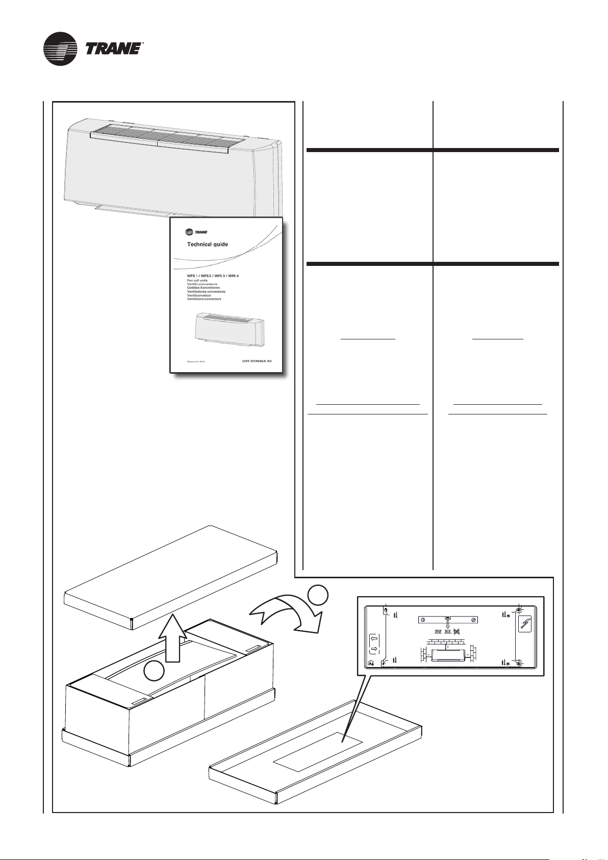
ATTENZIONE!
Nella parte interna
dell’imballo superiore
è presente
la dima di installazione.
Livello di pressione sonora
ponderata in scala A < 70 dB(A)
I ventilconvettori sono stati studiati
per riscaldare e/o condizionare gli
ambienti e devono quindi essere
utilizzati solamente per questo. Si
esclude qualsiasi responsabilità per
i danni eventuali causati da un uso
improprio.
• Appliance.
• Instruction
and maintenance manual.
GENERAL
WARNINGS
After removing the packaging, make
sure the contents are as requested
and not damaged. If this is not the
case, contact the dealer where you
bought the appliance.
IMPORTANT!
The installation template
is present
inside the upper packaging.
The A-weighted sound
pressure level < 70 dB(A)
The fan coils have been designed
for room heating and/or air conditioning
and must be used exclusively for that
purpose. We declines all responsibility
for damage caused by their improper
use.
Ogni riparazione o manutenzione dell’apparecchio deve essere eseguita da
All repairs or maintenance must be
performed by qualified specialists.
personale specializzato e qualificato.
Non si risponde in caso di danni
provocati da modifiche o manomissioni dell’apparecchio.
We declines all responsibility for
damage caused by modifications
or tampering with the unit.
UNT-SVX036A-XX13
Page 25
REMARQUES
GENERALES POUR
LA LIVRAISON
ALLGEMEINE
HINWEISE
ZUR LIEFERUNG
NOTAS
GENERALES
PARA LA ENTREGA
ALGEMEINE
OPMERKINGEN
BIJ DE LEVERING
• Appareil.
• Instructions
d’installation et d’entretien.
GENERALITES
Après avoir ouvert et retiré l’emballage, s’assurer que le contenu
est conforme et qu’il est en parfait
état. En cas contraire s’adresser au
revendeur où l’appareil a été acheté.
ATTENTION!
Sur la partie interne
de l'emballage supérieur
se trouve
le gabarit d'installation.
Le niveau de pression sonore
pondéré A < 70 dB(A)
Les ventilo-convecteurs ont été conçus
pour chauffer et/ou climatiser les
pièces et ne doivent être destinés qu’à
cet usage. Il exclut toute responsable
en cas de dommages causés par
un emploi anormal.
• Gerät.
• Gebrauchs und Wartungsanleitung.
ALLGEMEINE
HINWEISE
Nach dem Auspacken kontrollieren,
ob der Inhalt der Bestellung entspricht
und unversehrt ist. Im gegenteiligen
Fall wenden Sie sich an Ihren Händler.
ACHTUNG!
In der oberen Verpackung
befindet sich
die Installationsanleitung.
Schalldruckpegel < 70 dB(A)
Die Gebläsekonvektoren wurden
zur entwickelt und dürfen folglich
ausschließlich zu diesem Zweck
verwendet werden. Die Firma haftet
nicht für eventuelle Schäden, die
durch den unzweckmäßigen Gebrauch
verursacht werden.
• Aparato.
• Manual de instrucciones
y mantenimiento.
ADVERTENCIAS
GENERALES
Después de haber retirado el embalaje,
comprobar que el contenido sea el
solicitado y que esté intacto. En caso
contrario, dirigirse al establecimiento
donde se ha comprado el aparato.
ATENCIÓN!
En la parte interna
del embalaje superior
se encuentra la plantilla
relativa a la instalación.
El nivel de presión sonora
con ponderación A < 70 dB(A)
Los fan coils se han estudiado para
calentar y/o acondicionar las habitaciones y no deben usarse para otro
fin. Declinamos cualquier responsabilidad por los posibles daños
debidos a un uso inadecuado.
• Apparaat.
• Handleiding voor het gebruik
en het onderhoud.
ALGEMENE
VOORSCHRIFTEN
Na de verpakking te hebben verwijderd,
controleren of de inhoud ervan correct
en onbeschadigd is. Is dit niet het geval,
contact opnemen met de verkoper of
waar het apparaat werd aangekocht.
OPGELET!
In de verpakking
bovenaan bevindt
zich het schema
voor de installatie.
Geluidsdrukniveau
gewogen schaal A < 70 dB(A)
De ventilatorconvectors werden ontworpen
voor de verwarming en/of koeling van
ruimten, en dienen uitsluitend hiervoor
te worden gebruikt. Wij kunnen niet
aansprakelijk worden gesteld voor
eventuele schade die het gevolg is van
een verkeerd gebruik van het apparaat.
Toutes les réparations ou entretiens de
l’appareil doivent être effectués par le
SAV ou par un technicien spécialisé.
On décline toute responsabilité en cas
de dommages provoqués par
modifications ou altérations de l’appareil.
des
Nur qualifiziertes und geschultes
Personal darf Reparaturen und die
Wartung an den Geräten vornehmen.
Die Firma haftet nicht für solche Schäden,
die durch eine Veränderung oder
Manipulation am Gerät entstehen.
Bei sämtlichen eingebauten Geräten
ist eine entsprechend große Revisionsöffnung für eine De- und Wiedermontage ohne Beschädigung der
Substanz für Wartungen und evtl.
Reparaturen vorzusehen!
Die Betriebsanleitung ist Teil der
Lieferung und Bestandteil des Gerätes.
Sie muss vor der Montage aufmerksam
gelesen und dem Bauherrn nach
Fertigstellung übergeben werden.
Die Gewährleistung kann nur nach
Vorlage der Betriebs- und Wartungsanleitung und entsprechend großer
Revisionsöffnung gewährt werden.
Ebenso entfällt der Gewährleistungsanspruch wenn die notwendige jährliche
Wartung der Geräte (durch die
Sabiatech od. durch einen nachweislich
befugten Fachbetrieb) nicht durchgeführt
wurde.
Todas las reparaciones o mantenimiento del aparato deberán ser realizadas
por personal especializado y cualificado.
No se hace responsable en caso de
daños provocados por modificaciones o manipulaciones del aparato.
Reparaties of onderhoud van het apparaat
dienen uitgevoerd te worden door
gespecialiseerd en opgeleid personeel.
Wij kunnen niet aansprakelijk worden
gesteld voor schade die voortvloeit
uit aangebrachte wijzigingen.
UNT-SVX036A-XX 13A
Page 26
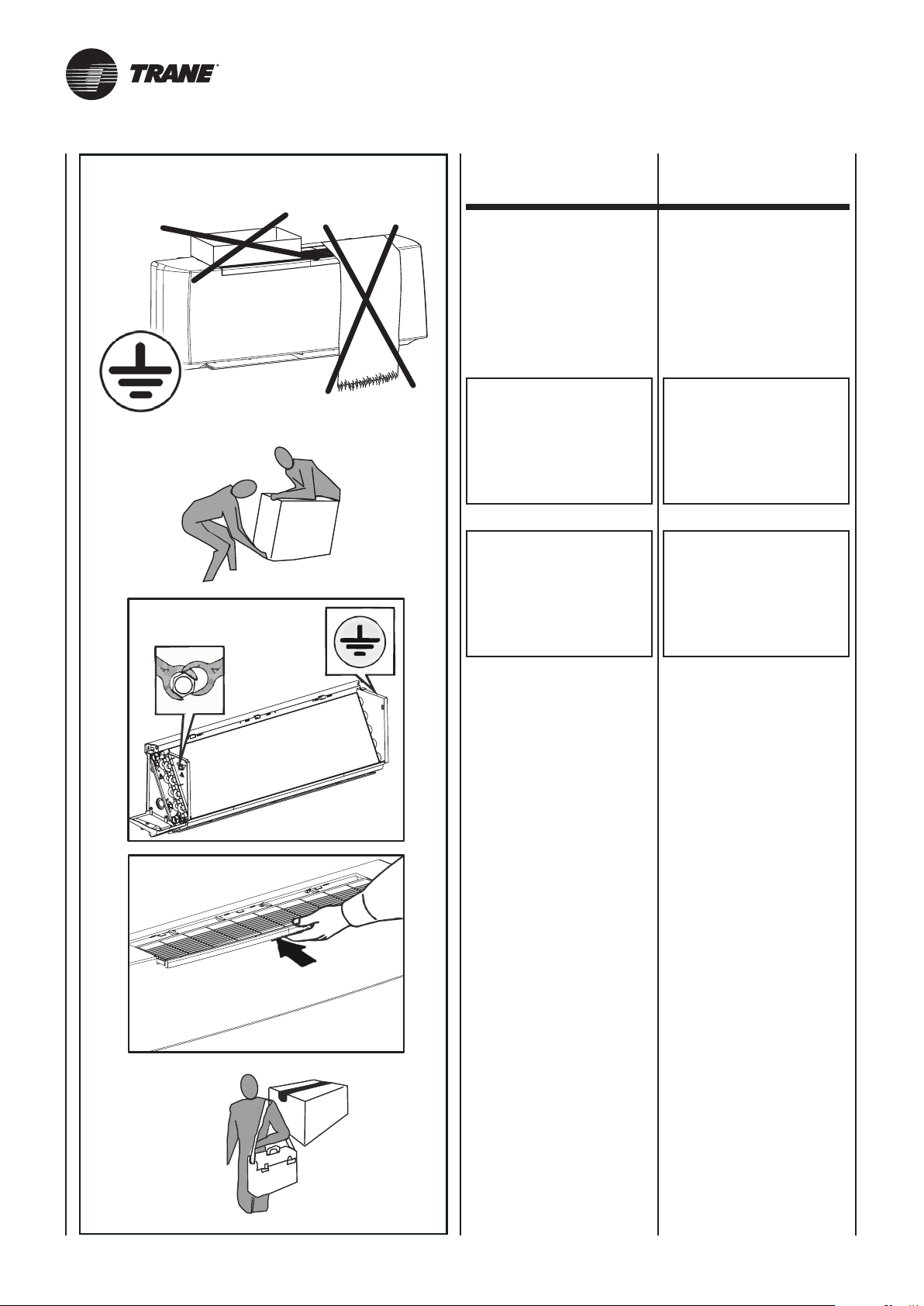
PRESCRIZIONI
DI SICUREZZA SAFETY RULES
Assicurarsi
di collegare la messa a terra.
Le ventole possono raggiungere
la velocità di 1000 g/min.
Non inserire oggetti nell’elettroventilatore nè tantomeno le mani.
ATTENZIONE!
NON TOGLIERE LA
PROTEZIONE
DEL CIRCUITO STAMPATO
DELLA SCHEDA
ELETTRONICA
DAL SUPPORTO COMANDI.
IN CASO DI SOSTITUZIONE
O PULIZIA DEL FILTRO
RICORDARSI SEMPRE
DI REINSERIRLO
PRIMA
DELL’AVVIAMENTO
DELL’APPARECCHIATURA.
Make sure
the unit is earthed.
Fan blades may reach speeds of
up to 1000 revs/min.
Never introduce objects or the hand
into the fans.
IMPORTANT!
DO NOT REMOVE
THE ELECTRICAL BOARD
PRINTED CIRCUIT
GUARD FROM
THE CONTROL UNIT
MOUNTING.
IF THE FILTER
REQUIRES
REPLACING OR CLEANING,
ALWAYS MAKE SURE
IT IS REPOSITIONED
CORRECTLY BEFORE
STARTING THE UNIT.
In caso di installazioni in climi particolarmente freddi, svuotare l’impianto idraulico in previsione di
lunghi periodi di fermo macchina.
In particularly cold climates, if the
appliance is not to be used for long
periods, drain the hydraulic circuit.
UNT-SVX036A-XX14
Page 27
CONSIGNES
DE SECURITE
SICHERHEITSVORSCHRIFTEN
PRESCRIPCIONES
DE SEGURIDAD
VEILIGHEIDSVOORSCHRIFTEN
S’assurer que la mise à la terre a
été effectuée.
Les ventilateurs peuvent atteindre
la vitesse de 1000 tr/mn.
Ne pas introduire d’objets dans le
ventilateur, et surtout pas les mains.
ATTENTION!
NE PAS RETIRER LA
PROTECTION DU CIRCUIT
IMPRIME DE LA CARTE
ELECTRONIQUE
DU SUPPORT
DES COMMANDES.
EN CAS
DE REMPLACEMENT OU
DE NETTOYAGE DU FILTRE,
NE JAMAIS OUBLIER
DE LE REMETTRE
AVANT DE METTRE
L’APPAREIL EN MARCHE.
Vergewissern Sie sich, dass das
Gerät korrekt geerdet wird.
Die Laufräder können eine Drehzahl
von 1.000 U/min. erreichen.
Stecken Sie keine Gegenstände in
den Ventilator, und greifen Sie erst
recht nicht mit den Händen hinein.
ACHTUNG!
DIE SCHUTZABDECKUNG
DER ELEKTRONIKPLATINE
DARF NICHT
VON DER HALTERUNG
DER STEUERUNGEN
GENOMMEN WERDEN.
BEI AUSTAUSCH ODER
REINIGUNG DES FILTERS
NICHT VERGESSEN, DEN
FILTER VOR DEM
ERNEUTEN EINSCHALTEN
DES GERÄTES WIEDER
EINZUBAUEN.
Comprobar siempre que
esté conectada la toma de tierra.
Los ventiladores pueden alcanzar
una velocidad de 1000 r.p.m.
No introducir objetos en el ventilador ni tanto menos las manos.
ATENCIÓN!
NO QUITAR LA PROTECCIÓN
DEL CIRCUITO IMPRESO
DA LA TARJETA
ELECTRÓNICA
DEL SOPORTE
DEL CONTROL.
EN CASO DE SUSTITUCIÓN
O DE LIMPIEZA DEL FILTRO
ACORDARSE SIEMPRE
DE COLOCARLO DE NUEVO
EN SU SITIO ANTES
DE PONER EN MARCHA
EL APARATO.
Zorg
voor een aardaansluiting.
De propellers kunnen een snelheid
van 1000 t/min. halen.
Steek geen voorwerpen of handen
in de elektronventilator.
OPGELET!
VERWIJDER
DE BEVEILIGING VAN HET
GEDRUKTE CIRCUIT
VAN DE ELEKTRONISCHE
SCHAKELING NIET
AN DE BEDIENINGSBASIS.
ALS U DE FILTER
VERVANGT
OF SCHOONMAAKT,
PLAATST U HEM STEEDS
TERUG VOOR
U HET APPARAAT
IN WERKING STELT.
En cas d’installation dans des climats
particulièrement froids, vidanger l’installation
hydraulique lorsqu’on prévoit de longues
périodes d’arrêt de la machine.
Bei Installation in einem besonders
kalten Klima muss der Wasserkreislauf
entleert werden, wenn das Gerät für
längere Zeit nicht benutzt wird.
En caso de instalación en climas particularmente fríos, vaciar la instalación
hidráulica si se prevén largos plazos
de parada de la máquina.
Voor een installatie in een bijzondere
koude omgeving, ledigt u de hydraulische
installatie als u voorziet dat de machine
gedurende een lange periode niet zal werken.
UNT-SVX036A-XX 14A
Page 28
LIMITI DI IMPIEGO OPERATING LIMITS
I dati fondamentali relativi al ventilconvettore e allo scambiatore di
calore sono i seguenti:
Ventilconvettore
e scambiatore di calore:
• Temperatura massima
del fluido termovettore:
max 70°C
• Temperatura minima
del fluido di raffreddamento:
min 6°C
• Pressione
di esercizio massima: 1000 kPa
• Tensione di alimentazione:
230V - 50Hz
• Consumo di energia elettrica:
vedi targhetta dati tecnici
• Grado di protezione: IP 20
I dati tecnici delle valvole con
azionatore termoelettrico sono i
seguenti:
Valvole con
azionatore termoelettrico:
•
Pressione di esercizio: 1000 kPa
• Tensione di alimentazione:
230V~50/60Hz
• Rating/protezione VA:
5 VA/IP 44
• Tempo di chiusura: 180 sec.
• Contenuto massimo
di glicole nell’acqua: 50%
The basic specification of the fan
coil and heat exchanger is given
below:
Fan coil
and heat exchanger:
• Maximum
temperature
of heat vector fluid: 70°C
• Minimum
temperature
of refrigerant fluid: 6°C
• Maximum
working pressure: 1000 kPa
• Power supply voltage:
230V - 50Hz
• Electric energy consumption:
see technical data label
• Index of protection: IP 20
The technical specification of the
valves with thermoelectric actuator
is given below:
Valves with
thermoelectric actuator:
• Working pressure: 1000 kPa
• Power supply voltage:
230V~50/60Hz
• Rating/VA protection:
5 VA/IP 44
• Closing time: 180 sec.
• Maximum glycol content
in water: 50%
Altri dati tecnici
Tutti gli altri dati tecnici importanti
(dimensioni, pesi, collegamenti, rumorosità, ecc.) vengono forniti in
altre parti del presente Manuale,
nella documentazione tecnica a
parte o nella proposta tecnica.
SMALTIMENTO
Le parti di consumo e quelle sostituite vanno smaltite nel rispetto della sicurezza e in conformità con le
norme di protezione ambientale.
Other technical data
All other important technical data
(dimensions, weights, connections,
noise emissions, etc.) are given
elsewhere in this User Information
Manual, in the separate technical
documentation or in the technical
proposal.
WASTE DISPOSAL
Consumables and replaced parts
should be disposed of safely and
in accordance with environmental
protection legislation.
UNT-SVX036A-XX15
Page 29
LIMITES D’EMPLOI BETRIEBSGRENZEN LÍMITES DE USO GEBRUIKSLIMIETEN
Les caractéristiques fondamentales
du ventilo-convecteur et de l’échangeur de chaleur sont les suivantes:
Ventilo-convecteur
et échangeur de chaleur:
• Température maximale
du fluide caloporteur:
70°C maxi
• Température minimale
du fluide de refroidissement:
6°C mini
• Pression
de marche maximale: 1000 kPa
• Tension d’alimentation:
230V - 50Hz
• Consommation
d’énergie électrique: voir
plaquette données techniques
• Degré de protection: IP 20
Les données techniques des
soupapes à actionneur thermoélectrique sont les suivantes:
Vannes
commande thermoélectrique:
• Pression de marche: 1000 kPa
• Tension d’alimentation:
230V~50/60Hz
• Degré de protection: 5 VA/IP 44
• Temps de fermeture: 180 sec.
• Contenu maximal de glycol
dans l’eau: 50%
à
Die wesentlichen Daten des Gebläsekonvektors und der Wärmetauscher
sind folgende:
Gebläsekonvektor
und Wärmetauscher:
• Min. Wassereintritts temperatur: 70°C
• Min. Wassereintritts temperatur: 6°C
• Max.
Betriebsdruck: 1000 kPa
• Versorgungsspannung:
230V - 50Hz
• Energieverbrauch:
siehe Typenschild
• Schutzgrad: IP 20
Die technischen Daten der thermoelektrischen Ventile sind folgende:
Ventile mit
thermoelektrischer Steuerung:
• Betriebsdruck: 1000 kPa
• Versorgungsspannung:
230V~50/60 Hz
• Rating/Sicherung VA:
5 VA/IP 44
• Verschlusszeit: 180 Sek.
• Max. Glykolanteil
im Wasser: 50%
Los datos fundamentales relativos
al ventilador convector y al intercambiador de calor son los siguientes:
Ventilador convector
e intercambiador de calor:
• Temperatura máxima
del fluido termovector:
máx. 70°C
• Temperatura mínima
del fluido de enfriamiento:
mín. 6°C
• Máxima
presión de ejercicio: 1000 kPa
• Tensiones de alimentación:
230V - 50Hz
• Consumo de energía eléctrica:
ver placa de datos técnicos
• Grado de protección: IP 20
Los datos técnicos de las válvulas
con accionador termoeléctrico son
los siguientes:
Válvulas con
accionador termoeléctrico:
• Presión de ejercicio: 1000 kPa
• Tensión de alimentación:
230V~50/60Hz
• Rating/protección VA:
5 VA/IP 44
• Tiempo de cierre: 180 seg.
• Contenido máximo
de glicol en el agua: 50%
De belangrijke gegevens met
betrekking tot de ventilatorconvector en de warmtewisselaar:
Ventilator-convector
en warmtewisselaar:
• Maximumtemperatuur
Vloeistof Thermovector:
max. 70°C
• Minimumtemperatuur
koelvloeistof:
min. 6°C
• Maximale
bedrijfsdruk: 1000 kPa
• Voedingsspanning:
230V - 50Hz
• Elektrisch
energieverbruik: zie plaatje
met technische gegevens
• Beschermingsgraad: IP 20
De technische gegevens van de
kleppen met thermo-elektrische
inschakeling:
Kleppen met thermoelektrische inschakeling:
• Bedrijfsdruk: 1000 kPa
• Voedingsspanning:
230V~50/60Hz
• Rating/VA-bescherming:
5 VA/IP 44
• Sluitingstijd: 180 sec.
• Maximaal
glycolgehalte water: 50%
Autres données techniques
Toutes les autres caractéristiques
techniques importantes (dimensions, poids, raccordements, bruit
etc.) sont indiquées dans d’autres
parties de ce livret, dans la documentation technique à part ou dans
la proposition technique.
Weitere technische Daten
Alle anderen wichtigen technischen
Daten (Abmessungen, Gewichte,
Anschlüsse, Geräuschpegel, usw.)
sind an anderen Stellen dieses
Handbuchs, in der separaten technischen Dokumentation oder in den
Angebotsunterlagen enthalten.
Otros datos técnicos
Todos los otros datos técncicos importantes (eida, pesos, conexiones,
ruido, etc.) se dan en otras partes
del presente Manual, en la documentación técnica.
Andere technische gegevens
Alle andere belangrijke technische
gegevens (afmetingen, gewichten,
aansluitingen, lawaai, enz.) worden
geleverd in andere delen van de
Handleiding, in de technische
documentatie of door het technisch
personeel.
ÉLIMINATION ENTSORGUNG ELIMINACIÓN AFDANKING
Les consommables et les pièces
remplacées doivent être éliminés
en respectant les règles de sécurité et les normes de protection de
l’environnement.
UNT-SVX036A-XX 15A
Verbrauchsteile und ersetzte Teile
müssen vorschriftsmäßig entsorgt
werden.
Las partes de consumo y las que
se sustituyen se eliminan respetando la seguridad y de acuerdo
con las normas de protección del
medio ambiente.
De verbruiksonderdelen en vervangen
onderdelen worden afgedankt met
respect voor de veiligheidsvoorschriften
en overeenkomstig de milieuwetgeving.
Page 30
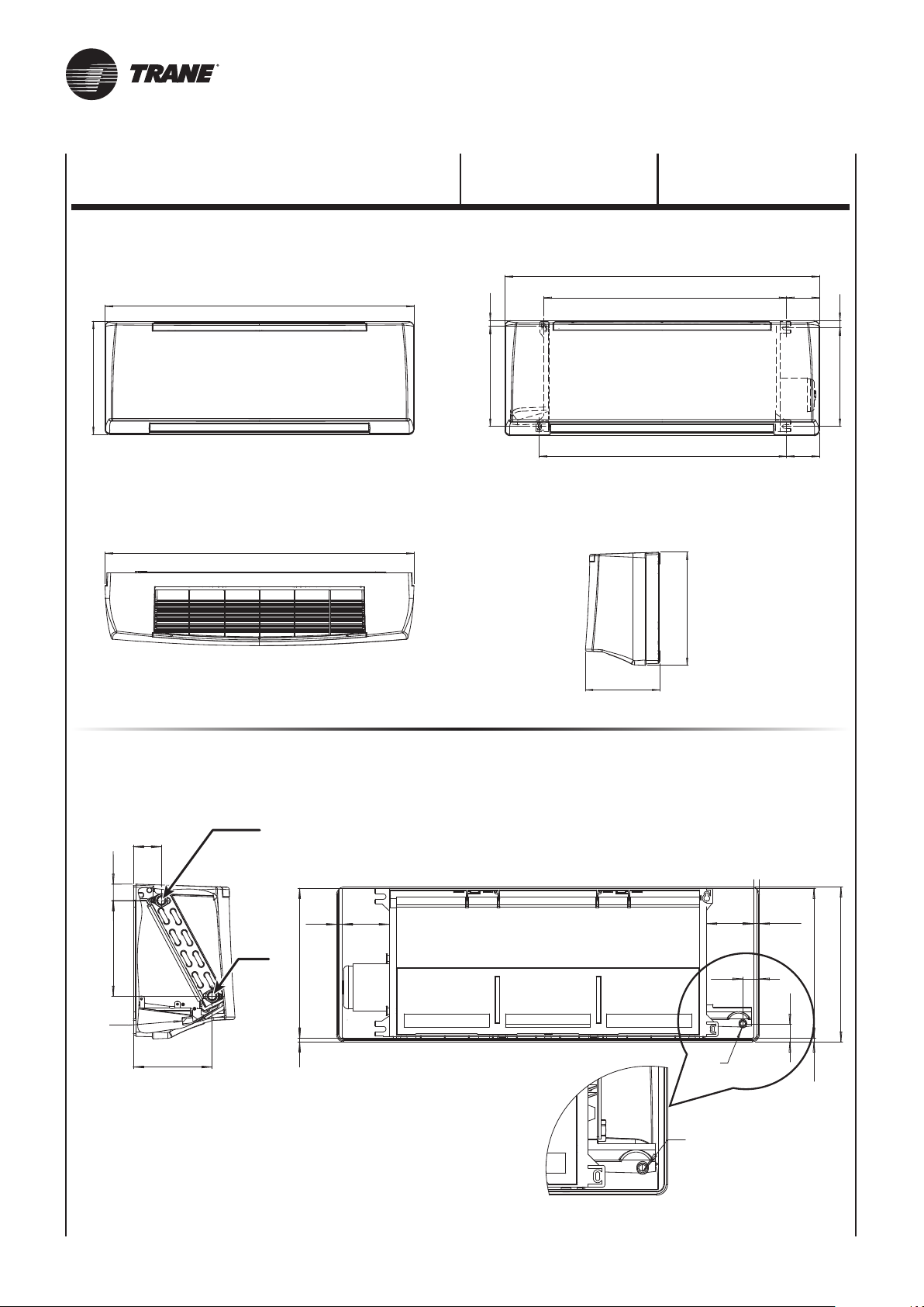
322
A
CARATTERISTICHE
TECNICHE
16 281
TECHNICAL
CHARACTERISTIC
A
B
92
20 276
C
A
322
212
ATTACCHI IDRAULICI - HYDRAULIC CONNECTIONS - WASSERANSCHLÜSSE
RACCORDS HYDRAULIQUES - CONEXIONES HIDRÁULICAS - HYDRAULISCHE AANSLUITINGEN
OUT
58
34
92
ø16
199
164
IN
12
8 311
97
Vista posteriore
Back sight
Vue arrière
Rückwärtige Sicht
Vista trasera
ø16
ø16
97
34
12
322
311
37
8
UNT-SVX036A-XX16
Page 31
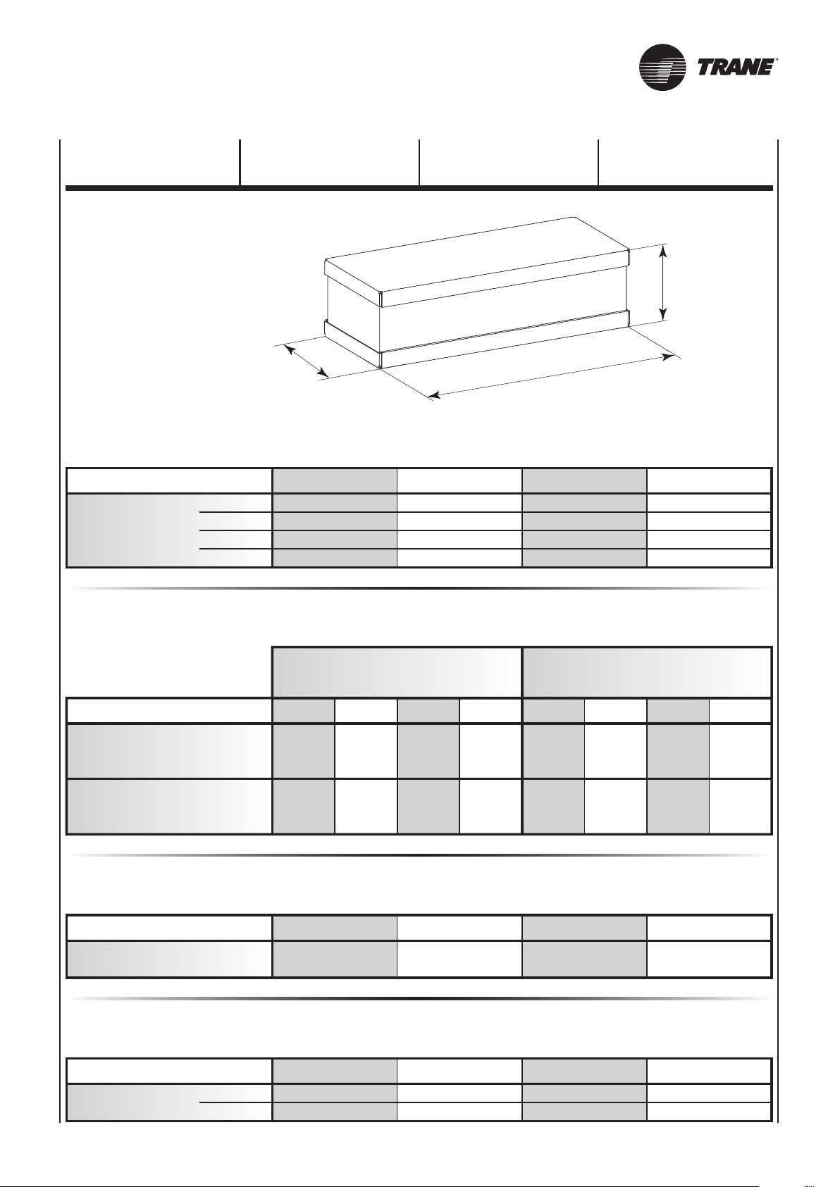
270
Z
395
CARACTERISTIQUES
TECHNIQUES
TECHNISCHE
EIGENSCHAFTEN
CARACTERÍSTICAS
TÉCNICAS
DIMENSIONI - DIMENSIONS - DIMENSIONS
DIMENSIONEN - DIMENSIÓN - AFMETINGEN
TECHNISCHE
KARAKTERISTIEKEN
mod.
A
mm
B
C
Z
mod.
senza valvole – without valves
sans vannes – Ohne ventile
sin válvulas – zonder kleppen
con valvole – with valves
avec vannes – mit ventile
con válvulas – met kleppen
1 2 3 4
880
678
691
950
GEWICHT - PESO - GEWICHT
Unità imballata - Packed unit
Unité emballée - Verpackung des Gerätes
Unidad embalada - Verpakte eenheid
1 2 3 4 1 2 3 4
kg
kg
12 1012 1016 1316 13
13 1113 1117 1417 14
CONTENUTO ACQUA - WATER CONTENTS - CONTENANCE EAU
WASSERINHALT - CONTENIDO AGUA - WATERINHOUD
880
678
691
950
PESO - WEIGHT - POIDS
Unidad sin embalar - Eenheid zonder verpakking
1185
983
996
1255
Unità non imballata - Unpacked unit
Unité seule - Unverpackung des Gerätes
1185
983
996
1255
mod.
Litri / Liters / Litres
Liter / Litros / Liter
ASSORBIMENTO MOTORE - MOTOR ABSORPTION - CONSOMMATION MOTEUR
mod.
230/1 50Hz
UNT-SVX036A-XX 16A
W
A
1 2 3 4
0,85 0,85 1,28 1,28
LEISTUNGSAUFNAHME MOTOR - COMSUMO MOTOR - MOTORABSORPTIE
1 2 3 4
30
0,16
32
0,16
46
0,23
48
0,23
Page 32
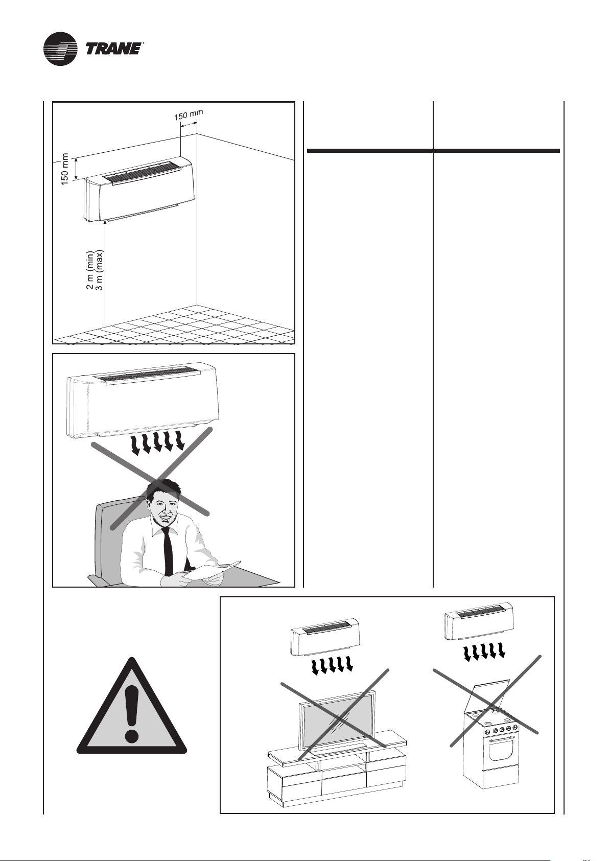
(Fig. B)
(Abb. B)
(Fig. C)
(Abb. C)
SCELTA
DELLA POSIZIONE
DELL’UNITÀ
La posizione di installazione dell’unità, per ottenere il miglior rendimento di funzionamento ed evitare
guasti o condizioni di pericolo, deve
avere i seguenti requisiti:
- L’altezza dal pavimento del filo
inferiore dell’unità deve essere
minimo di 2 m e massimo di 3 m
(Fig. B).
-
La parete su cui si intende fissa re l’unità deve essere robusta e
adatta a sostenerne il peso.
- Deve essere possibile lasciare
attorno all’unità uno spazio neces-
sario per eventuali operazioni di
manutenzione.
-
Non devono essere presenti osta-
coli per la libera circolazione del-
l’aria sia dal lato aspirazione che,
in maggior luogo, su quello di
uscita aria; in questo particolare
caso non deve essere presente
nessun ostacolo ad una distanza
inferiore i 2 m. Ciò potrebbe ca-
usare turbolenze tali da inibire il
corretto funzionamento dell’ap parecchio.
- Deve possibilmente essere una
parete esterna in modo da poter
convogliare verso l’esterno il dre naggio della condensa.
SELECTION
OF POSITION
OF THE UNIT
The position for installation of the
unit, to obtain the best performance
and prevent breakdowns or hazards,
must have the following requisites:
- The bottom of the unit must be
at least 2 meters off the floor and
no more than 3 (Fig. B).
- The wall on which the unit is
installed must be sturdy and able
to withstand its weight.
It must be possible to leave room
around the unit for any maintenance
operations that may be necessary.
- There should be no obstacles
to the free circulation of air on
the intake side and, especially,
on the air outlet side; on this side,
in particular, there should be no
obstacles closer than 2 m. This
could cause turbulence that would
interfere with correct operation
of the unit.
-
If possible, it should be installed
on an external wall so as to
convey the condensation drain
outside.
(Fig. D)
(Abb. D)
-
Non deve essere in una posizio-
ne tale che il flusso dell’aria sia
rivolto direttamente alle persone
sottostanti (Fig. C).
- Non sia direttamente sopra ad
un apparecchio elettrodomestico
(televisore, radio, frigorifero, ecc.),
o sopra ad una fonte di calore
(Fig. D).
- It should not be installed in a
position where the air flow can
strike the people underneath
directly (Fig. C).
- It should not be directly over
another appliance (television set,
radio, refrigerator, etc.), or over
a source of heat (Fig. D).
UNT-SVX036A-XX17
Page 33
CHOIX
DE LA POSITION
DE L’UNITE
POSITIONIERUNG
DER EINHEIT
ELECCIÓN
DE LA POSICIÓN
DE LA UNIDAD
POSITIONERINGSEENHEID
Pour obtenir le meilleur rendement
de fonctionnement et éviter les pannes
ou les situations de danger, la position
d’installation de l’unité doit avoir les
caractéristiques suivantes:
- La hauteur du bord inférieur de
l’unité doit être au moins à 2 m et
au maximum à 3 m du sol (Fig. B).
- Le mur sur le quel on souhaite
fixer l’unité doit être solide et apte
à en supporter le poids.
Il faut prévoir de laisser l’espace
nécessaire autour de l’unité pour
d’éventuelles opérations d’entretien.
- Il ne doit y avoir aucun obstacle
pour la libre circulation de l’air
tant du côté de l’aspiration que,
à plus forte raison, sur celui de la
sortie de l’air; pour ce dernier cas
il ne doit y avoir aucun obstacle à
une distance inférieure à 2 m. Cela
pourrait causer des turbulences qui
pourraient empêcher le fonctionnement correct del’appareil.
-
Il est préférable, autant que possible,
que ce soit un mur donnant sur
l’extérieur de sorte que l’on puisse
diriger le drainage de la condensation
au dehors.
-
L’installation ne doit pas être dans
une position telle que le soufflage
de l’air soit dirigé directement sur
les personnes placées au-dessous
(Fig. C).
-
Elle ne doit pas être directement
audessus d’un appareil électro-
ménager (téléviseur, radio, réfrigérateur, etc.), ou au-dessus d’une
source de chaleur (Fig. D).
Zur Gewährleistung einer einwandfreien
Funktionsweise und zur Vorbeugung von
Betriebsstörungen und Gefahren ist bei der
Wahl der Stelle, an der die Einheit installiert
werden soll, auf Folgendes zu achten:
-
muss mind. 2 mbis max. 3 m
betragen (Abb. B).
- Die Wand, an der die Einheit
derselben standhalten.
-
eventuelle Wartungseingriffe
vorgenommen werden können.
- An der Luftansaug- und Luft-
Abstand von mind. 2 m keine
Turbulenzen führen könnte, die
des Gerätes beeinträchtigen
könnten.
- Nach Möglichkeit sollte eine
das Kondenswasser ins Freie
abgeleitet werden kann.
- Bei der Installation der Einheit
ist darauf zu achten, dass der
Luftstrom nicht direkt auf sich
darunter befindliche Personen
gerichtet ist (Abb. C).
Elektrogerät (TV, Radio, Kühl schrank, usw.) oder über einer
Wärmequelle installiert werden
(Abb. D).
La posición de instalación de la unidad, para obtener el mejor rendimiento de funcionamiento y evitar
daños o condiciones de peligro, tiene
que tener los siguientes requisitos:
-
Der Abstand zwischen dem Fußboden
und der unteren Kante der Einheit
befestigt wird, muss dem Gewicht
Die Einheit ist so anzubringen, dass
an dieser jederzeit und problemlos
auslassseite dürfen sich in einem
Hindernisse befinden, da dies zu
die einwandfreie Funktionsweise
Außenwand vorhanden sein, damit
Die Einheit darf nicht über einem
La altura desde el suelo del borde
inferior de la unidad tiene que
ser de un mínimo de 2 m y un
máximo de 3 m (Fig. B).
-
La pared sobre la que se quiere
fijar la unidad tiene que ser robu-
sta y apta para sostener el peso.
- Tiene que ser posible dejar
alrededor de la unidad un espacio
necesario para eventuales ope raciones de mantenimiento.
- No tiene que haber obstáculos
para la libre circulación del aire
tanto del lado de aspiración que,
sobre todo, del lado de salida de
aire; en este caso en particular
no tiene que haber ningún obstá-
culo a una distancia inferior de 2 m.
Esto podría causar turbulencias
tales que inhiban el correcto fun cionamiento del equipo.
-
Posiblemente tiene que ser una
pared externa de modo tal de
poder transportar hacia el exterior
el drenaje de la condensación.
-
No tiene que encontrarse en una
posición tal que el flujo de aire se
dirija directamente a las personas
subyacentes (Fig. C).
-
No se encuentre directamente por
encima de un electrodoméstico
(como por ejemplo: televisor, radio,
frigorífico, etc.), o sobre una fuente
de calor (Fig. D).
Om het beste werkingsrendement te
bekomen en om defecten of gevaarlijke
situaties te vermijden, moet de
installatiepositie van de eenheid aan
de volgende vereisten voldoen:
- De hoogte boven de vloer van
de onderste lijn van de eenheid
moet minimaal 2 m en maximaal
3 m bedragen (Fig. B).
-
De wanden waarop men de eenheid
wil bevestigen, moet stevig zijn en
geschikt om het gewicht te dragen.
-
Rond de eenheid moet men voldoende
ruimte kunnen laten voor eventuele
onderhoudswerkzaamheden.
-
Er mogen geen obstakels aanwezig
zijn voor de vrije luchtcirculatie,
zowel aan de kant van de aanzuiging
als aan de kant van de luchtuitlaat,
wat nog belangrijker is; in dit laatste
geval mag er geen enkel obstakel
aanwezig zijn op een afstand van
minder dan 2 m. Dit zou turbulenties
kunnen veroorzaken, die bijgevolg de
correcte werking van het toestel
beletten.
-
Indien mogelijk moet er een externe
wand zijn, zodat de afgevoerde
condens naar buiten kan worden
geleid.
-
Die mag niet in een stand staan
waardoor de luchtstroom rechtstreeks
naar personen eronder is gericht
(Fig. C).
-
De positie mag niet rechtstreeks
boven een huishoudtoestel
(televisie, radio, koelkast, enz.)
of boven een warmtebron zijn
(Fig. D).
UNT-SVX036A-XX 17A
Page 34
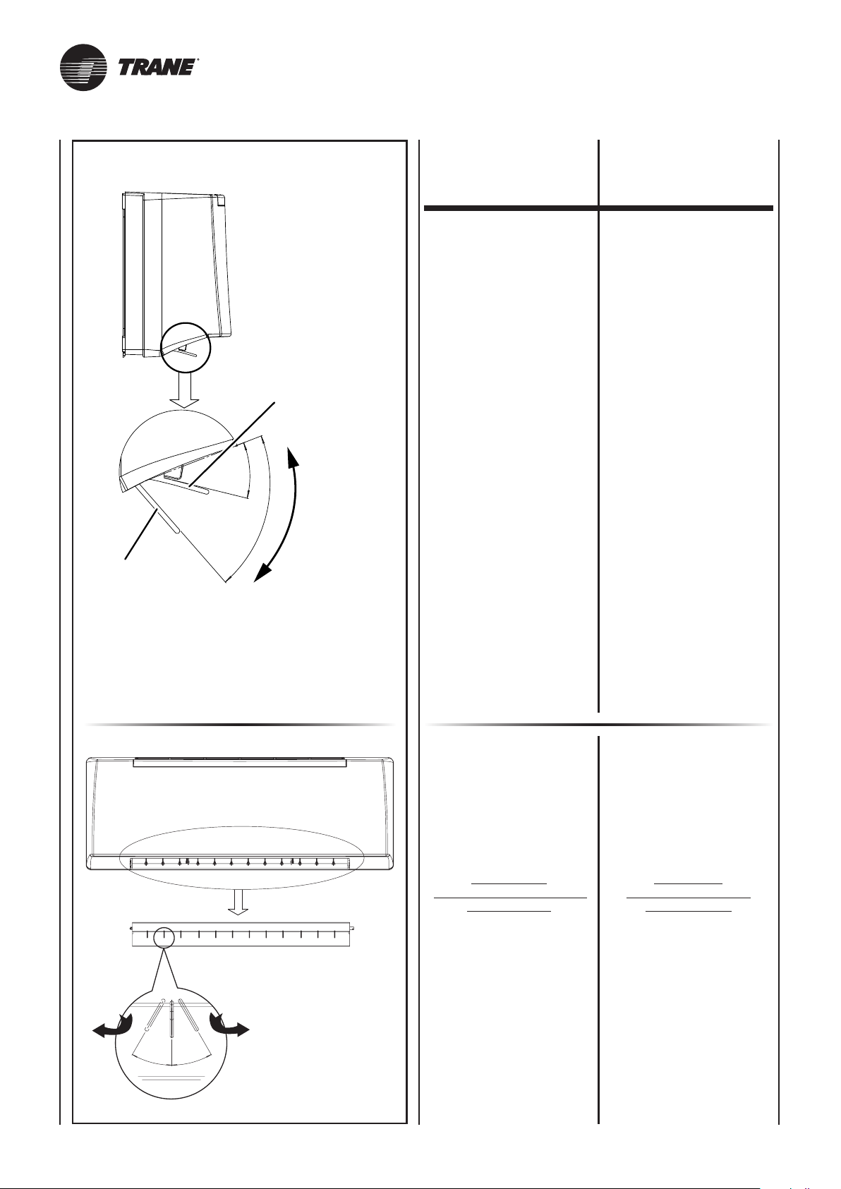
RAFFREDDAMENTO
CON FLUSSO
ARIA DI COMFORT 35˚
COOLING WITH
35° COMFORT AIR FLOW
REFROIDISSEMENT
AVEC FLUX
D'AIR DE CONFORT 35°
KÜHLUNG MIT
KOMFORT-LUFTFLUSS 35°
ENFRIAMIENTO
CON FLUJO DE AIRE
DE COMFORT 35˚
KOELING MET COMFORT
LUCHTSTROOM 35˚
CONTROLLO
DIREZIONE
FLUSSO ARIA
AIR FLOW
DIRECTION
CONTROL
35°
70°
RISCALDAMENTO
CON FLUSSO
ARIA DI COMFORT 70˚
HEATING WITH 70° COMFORT AIR FLOW
CHAUFFAGE AVEC FLUX D'AIR DE CONFORT 70°
HEIZUNG MIT KOMFORT-LUFTFLUSS 70°
CALEFACCIÓN CON FLUJO DE AIRE DE COMFORT 70˚
VERWARMING MET COMFORT LUCHTSTROOM 70˚
FLAP
GESTIONE FLUSSO ARIA
VERTICALE
Il flusso aria verticale
è regolabile manualmente.
ALETTE
GESTIONE FLUSSO ARIA
ORIZZONTALE
Il flusso aria orizzontale
(destra/sinistra)
è regolabile manualmente.
FLAP
VERTICAL
AIR FLOW MANAGEMENT
The vertical air flow
can be manually adjusted.
FLAPS
HORIZONTAL
AIR FLOW MANAGEMENT
The horizontal air flow
(right/left)
can be manually adjusted.
30°
30°
ATTENZIONE!
La regolazione va effettuata
con i flap fermi.
È possibile regolare le alette
fino ad un massimo
di 30° a destra
e fino ad un massimo
di 30° a sinistra.
La direzione
e la portata del flusso dell’aria
devono essere regolate
in modo che l’aria dall’unità
non soffi direttamente
sulle persone
che sono nel locale.
ATTENTION!
Flaps must be stopped
when adjusting.
The flaps can be adjusted
up to a maximum of 30°
to the right
and up to a maximum of 30°
to the left.
The air flow rate
and direction must be adjusted
so the air from the unit
does not directly blow
on people
present in the room.
UNT-SVX036A-XX18
Page 35
CONTRÔLE
DE LA DIRECTION
DU FLUX D'AIR
REGELUNG
DER LUFTFLUSSRICHTUNG
CONTROL
DE LA DIRECCIÓN
DEL FLUJO DE AIRE
CONTROLE
RICHTING
LUCHTSTROOM
FLAP
GESTION DU FLUX D'AIR
VERTICAL
Le flux d'air vertical
peut être réglé manuellement.
AILETTES
GESTION DU FLUX D'AIR
HORIZONTAL
Le flux d'air horizontal
(droit/gauche)
peut être réglé manuellement.
FLAP
STEUERUNG VERTIKALER
LUFTFLUSS
Der vertikale Luftfluss
kann manuell geregelt werden.
KLAPPEN
STEUERUNG HORIZONTALER
LUFTFLUSS
Der horizontale Luftfluss
(rechts/links)
kann manuell geregelt werden.
FLAP
GESTIÓN DEL FLUJO DE AIRE
VERTICAL
El flujo de aire vertical puede
regularse de forma manual.
ALETAS
GESTIÓN DEL FLUJO DE AIRE
HORIZONTAL
El flujo de aire horizontal
(derecha/izquierda) puede
regularse de forma manual.
FLAP
BEHEER VERTICALE
LUCHTSTROOM
De verticale luchtstroom
kan handmatig worden geregeld.
VINNEN
BEHEER HORIZONTALE
LUCHTSTROOM
De horizontale luchtstroom
(rechts/links)
kan handmatig worden geregeld.
ATTENTION!
Le réglage doit être effectué
avec les flaps à l'arrêt.
Il est possible de régler
les ailettes jusqu'à 30°
maximum à droite
et jusqu'à 30°
maximum à gauche.
La direction
et le débit du flux d'air
doivent être réglés
afin que l'air de l'unité
ne souffle pas directement
sur les personnes
qui sont dans la pièce.
UNT-SVX036A-XX 18A
ACHTUNG! Die Regelung
hat bei stillstehenden Klappen
zu erfolgen.
Die Klappen können
bis maximal 30° rechts
und bis maximal 30°
links eingestellt werden.
Die Richtung sowie
der Durchsatz des Luftflusses
müssen so geregelt werden,
dass die aus der Einheit
austretende Luft
nicht direkt die Personen
im Raum trifft.
ATENCIÓN!
La regulación se hace
con los flaps parados.
Pueden regularse las aletas
hasta un máximo
de 30° hacia la derecha
y hasta un máximo
de 30° hacia la izquierda.
La dirección
y la capacidad del flujo del aire
deben regularse
de manera que el aire
de la unidad no sople
directamente hacia las personas
que están en la habitaciónœ.
OPGEPAST! De regeling
moet worden uitgevoerd terwijl
de flaps gestopt zijn.
De vinnen kunnen worden
geregeld tot een maximum
van 30° naar rechts
en tot een maximum
van 30° naar links.
De richting
en het debiet van de luchtstroom
moeten worden geregeld zodat
de lucht van de eenheid
niet rechtstreeks
op personen in het lokaal
gaat blazen.
Page 36
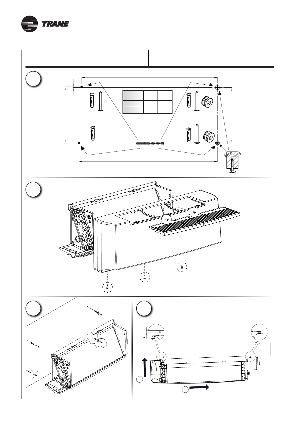
1
2
281
4
mod.
1 – 2
3 – 4
INSTALLAZIONE
MECCANICA
B
C
B
678
691
983
996
ø6
C
MECHANICAL
INSTALLATION
276
3 4
2
10
1
UNT-SVX036A-XX19
Page 37
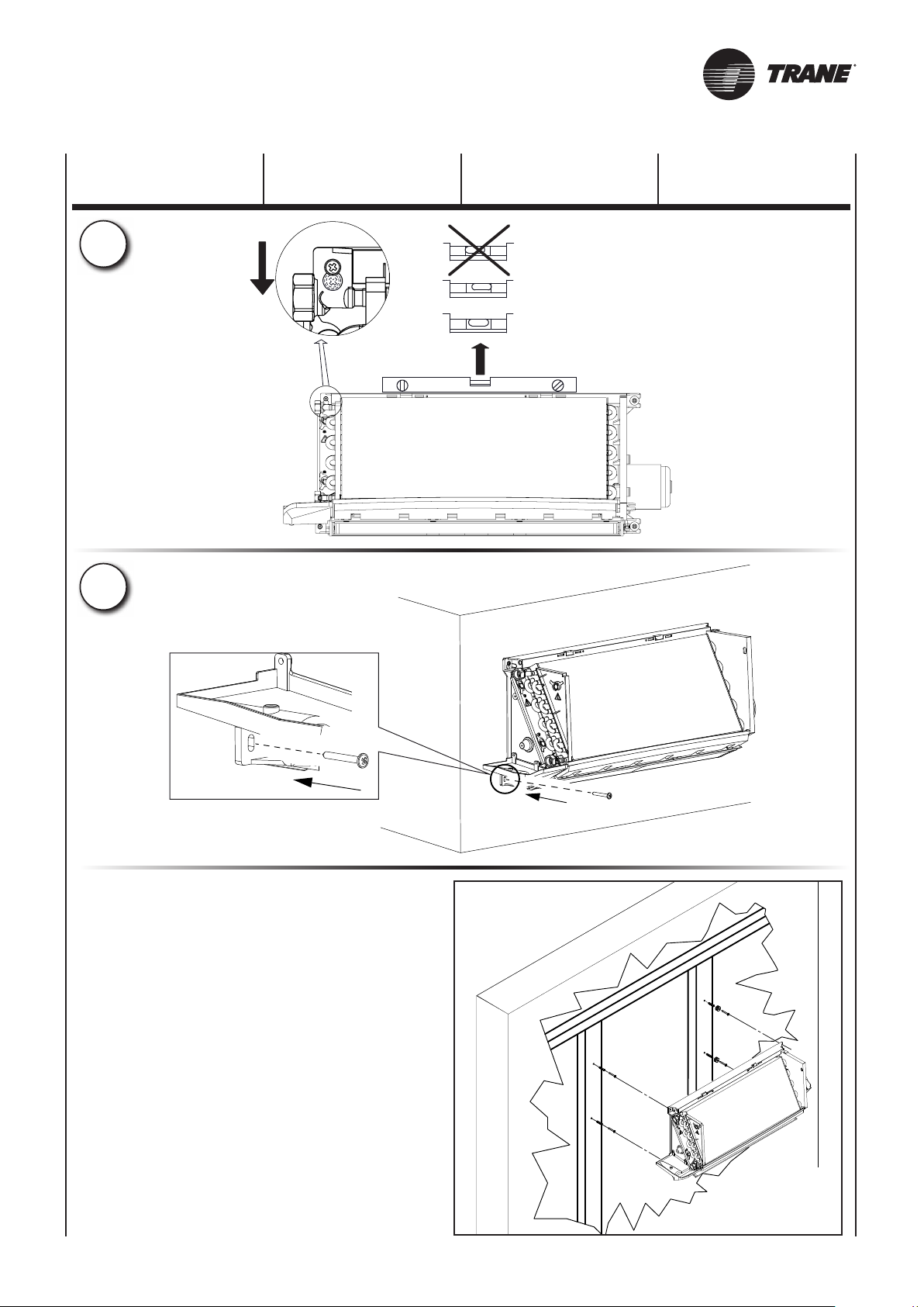
INSTALLATION
MECANIQUE
5
6
MECHANISCHE
INSTALLATION
INSTALACIÓN
MECÁNICA
OK
OK
MECHANISCHE
INSTALLATIE
Pareti in cartongesso o legno
Wood or plasterboard walls
Murs en placoplâtre ou en bois
Wände aus Gipskarton oder Holz
Paredes de cartón-yeso o de madera
Wanden in gipsplaat of hout
UNT-SVX036A-XX 19A
Page 38
COLLEGAMENTO
IDRAULICO
HYDRAULIC
CONNECTIONS
RACCORDEMENT
HYDRAULIQUE
Valori massimi ammissibili per l'acqua utilizzata all'interno di un circuito chiuso di raffreddamento o riscaldamento.
Water parameter
Parametri acqua
Limit values for the water used in closed heating and cooling circuits.
Caractéristiques de l'eau
Valeurs limites pour l’eau utilisé dans un circuit fermé de refroidissement ou de chauffage.
Parametro
Parameter / Paramètre
Valore pH (a 20°C)
pH value (at 20°C)
Valeur du Ph (à 20°C)
Conduttività (a 20°C)
Conductivity (at 20°C)
Conductivité (à 20°C)
Contenuto di Ossigeno
Oxygen content
Contenu Oxygène
Durezza Totale
Total hardness
Dureté Totale
Ioni Zolfo
Dissolved Sulphur
Ions Soufre
Ioni Sodio
Sodium
Ions Sodium
Ioni Ferro
Iron
Ion Fer
Ioni Manganese
Manganese
Ions Manganèse
Ioni Ammoniaca
Ammonium content
Ions Ammoniac
Ioni Cloro
Chloride
Ions Chlore
Ioni Solfato
Sulphate
Ions Sulfate
Ione Nitrito
Nitrite
Ion Nitrite
Ione Nitrato
Nitrate
Ion Nitrate
–
–
O2
–
S
+
Na
Fe2+, Fe
2+
Mn
NH
4
-
Cl
SO
4
NO
2
NO
3
3+
+
2-
-
-
Unità
Unit / Unité
–
μS/cm
mg/l
°dH
–
mg/l
mg/l
mg/l
mg/l
mg/l
mg/l
mg/l
mg/l
Value / Valeur
non rilevabile
undetectable
pas détectable
Valore
8 - 9
< 700
< 0,1
1 - 15
< 100
< 0,1
< 0,05
< 0,1
< 100
< 50
< 50
< 50
dai materiali in sospensione per mezzo di un filtro che deve trovarsi in ingresso (altrimenti c'è il rischio di erosione da particelle
de les substances polluantes avec un filtre, qui devrait être placé à l'entrée du réseau. Autrement il y a le risque de corrosion à cause
Nei circuiti aperti (ad esempio quando si utilizza acqua di pozzo), l'acqua utilizzata deve essere ripulita
in sospensione). È inoltre necessario assicurarsi che l'unità sia protetta da polvere e altre sostanze che provocano
una reazione acida o alcalina quando combinate con l'acqua (corrosione dell'alluminio).
On open system (e.g. when using well water), the water used should be cleaned from suspended matter by means
of a filter which should be located in the inlet. Otherwise there is a risk of erosion due to suspended matter.
You must also ensure that the unit is protected from dust and other substances that cause
an acid or alkali reaction when combined with water (aluminum corrosion).
Dans les circuits ouverts (par exemple lorsqu'on utilise l'eau d'un puit), l'eau utilisé doît être à nouveau renettoyé
des substances polluantes. En autre il faut s'assurer que l'unité soit protégée de la poussière et d'autres substances
qui provoquent une réaction acide ou alcaline, si mélangées avec de l'eau (corrosion aluminium).
UNT-SVX036A-XX20
Page 39
WASSERANSCHLUSS ENLACE HIDRÁULICO
HYDRAULISCHE
AANSLUITING
Grenzwerte bezüglich des in einer geschlossenen Kühlung und Heizunganlage benutzen Wassers.
Parámetros agua
Wasser Parameter
Valores máximos admisibles para el agua usada dentro de un circuito cerrado de enfriamiento o calefacción.
Waterparameters
Toegestane maximumwaarden voor het water gebruikt in een gesloten circuit voor koeling of koeling.
Parameter
Parámetro / Parameter
Ph Wert (um 20°C)
pH (a 20 °C)
pH (bij 20°C)
Leitfähigkeit (um 20°C)
Conductividad (a 20 °C)
Geleidingsvermogen (bij 20°C)
Sauerstoff Inhalt
Contenido de Oxígeno
Zuurstofgehalte
Gesamte Härte
Dureza Total
Totale hardheid
Schwefel Ionen
Iones Azufre
Zwavelionen
Natrium Ionen
Iones Sodio
Natriumionen
Eisen Ion
Iones Hierro
IJzerionen
Mangan Ionen
Iones Magnesio
Mangaanionen
Ammoniak Ionen
Iones Amoniaco
Ammoniakionen
Chlor Ionen
Iones Cloro
Chloorionen
Sulfat Ionen
Iones Sulfato
Sulfaationen
Nitrit Ion
Ion Nitrito
Nitrietionen
Nitrat Ion
Ion Nitrato
Nitraationen
–
–
O2
–
S
+
Na
Fe2+, Fe
2+
Mn
NH
4
-
Cl
SO
4
NO
2
NO
3
3+
+
2-
-
-
Einheit
Unidad / Eenheid
–
μS/cm
mg/l
°dH
–
mg/l
mg/l
mg/l
mg/l
mg/l
mg/l
mg/l
mg/l
Wert
Valor / Waarde
8 - 9
< 700
< 0,1
1 - 15
nicht feststellbar
no detectable
niet meetbaar
< 100
< 0,1
< 0,05
< 0,1
< 100
< 50
< 50
< 50
Bei geöffneten Anlagen (z.B zum Gebrauch des Wassers eines Brunnens) muss das Wasser, durch einen am Eintritt eingestellten Filter,
noch einmal von den Schwebstoffen gesäubert werden. Ansosten besteht die Gefahr einer Erosion durch Schwebstoffe.
Es ist außerdem zu beachten, die Einheit vor Staub und anderen Stoffen zu beschützen, welche eine Säure - Base
oder alkalische Reaktionen verursachen könnten, sollten sie mit Wasser in Verbindung kommen (Ätzen des Aluminiums).
En los circuitos abiertos (por ejemplo, cuando se usa agua de pozo), el agua usada se debe limpiar aún más
para eliminar los materiales en suspensión, usando un filtro que debería estar en entrada. De lo contrario existe el riesgo
de erosión debido a las partículas en suspensión. Además, es necesario asegurarse de que la unidad esté protegida
contra el polvo y otras sustancias que provocan reacción ácida o alcalina cuando se combinan con el agua (corrosión del aluminio).
In open circuits (bijvoorbeeld wanneer men putwater gebruikt), moet het gebruikte water verder worden gezuiverd om materialen
in suspensie te verwijderen met behulp van een filter op de ingang. Anders bestaat er risico voor erosie door de deeltjes in suspensie.
UNT-SVX036A-XX 20A
Bovendien is het nodig om te verzekeren dat de groep beschermd is tegen stof en andere substanties
die een zure of alkalische reactie veroorzaken wanneer die met water worden gecombineerd (corrosie van aluminium).
Page 40
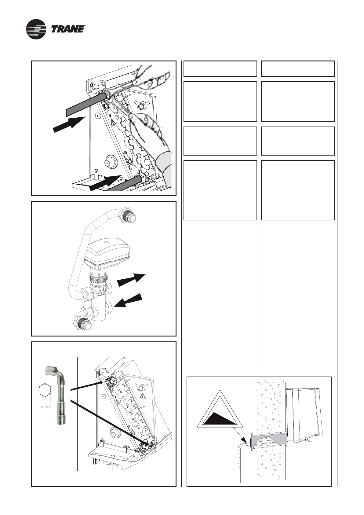
PRESSIONE MASSIMA
DI ESERCIZIO: 1000 kPa.
MAXIMUM WORKING
PRESSURE: 1000 kPa.
OUT
USARE SEMPRE
CHIAVE E CONTROCHIAVE
PER L’ALLACCIAMENTO
DELLA BATTERIA
ALLE TUBAZIONI.
PREVEDERE SEMPRE
UNA VALVOLA
DI INTERCETTAZIONE
DEL FLUSSO IDRAULICO.
ATTENZIONE!
È CONSIGLIATO SIFONARE
LO SCARICO
DELLA CONDENSA,
INSTALLARE
IL TUBO
DI SCARICO CONDENSA
CON UNA PENDENZA
DI ALMENO 3 cm/metro.
Nel caso l’apparecchio sia fornito
di valvola collegare i tubi di collegamento alla valvola stessa.
Se l’apparecchio è usato per raffreddare, per evitare gocciolamento
di condensa, isolare le tubazioni e
la valvola.
ALWAYS USE
TWO SPANNERS
TO CONNECT
THE HEAT EXCHANGER
TO THE PIPES.
ALWAYS
FIT A GATE VALVE
IN THE WATER CIRCUIT.
IMPORTANT!
YOU ARE RECOMMENDED
TO FIT A SIPHON
ON THE CONDENSATE
DRAIN. INSTALL
A CONDENSATE
DRAIN PIPE
WITH A SLOPE OF
AT LEAST 3 cm/metre.
If the unit is fitted with a valve,
connect the connection pipes to
the valve.
If the unit is used for cooling,
insulate the pipes and valve to
avoid drops of condensate forming.
8
IN
Nei periodi estivi e per lunghi periodi di tempo con il ventilatore disinserito, per evitare formazioni di
condensa all’esterno dell’apparecchio, si consiglia di intercettare
l’alimentazione della batteria.
Nel caso venga richiesta la vaschetta supplementare, raccolta
condensa, questa va fissata alla
struttura dal lato attacchi e il tubo
di scarico condensa va collegato
a quest’ultima.
3%
During the summer and when the
fan is inactive for long periods, you
are recommended to shut off the
water supply to the coil to avoid
condensation forming on the outside
of the unit.
If a supplementary condensate
drain pan is used, this should be
fixed to the connections side of
the frame and the condensate
drain pipe should be fastened to
the latter.
UNT-SVX036A-XX21
Page 41
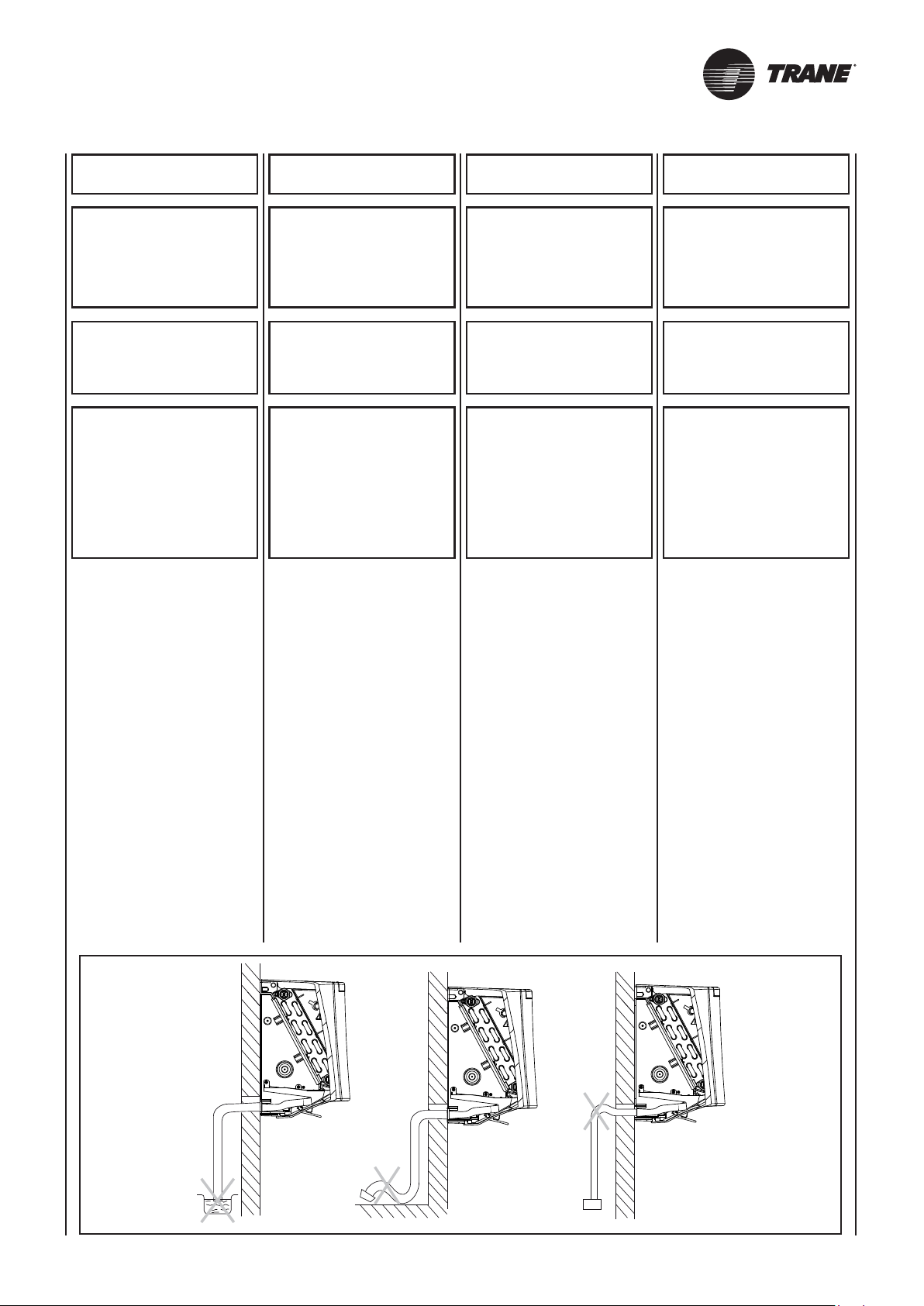
PRESSION MAXI
DE SERVICE: 1000 kPa.
BETRIEBSDRUCK: 1000 kPa.
MAXIMALER
PRESIÓN MÁXIMA
DE OPERACIÓN: 1000 kPa.
BEDRIJFSDRUK: 1000 kPa.
MAXIMALE
UTILISER TOUJOURS
UNE CLE
ET UNE CONTRE-CLE
POUR LE RACCORDEMENT
DE LA BATTERIE
AUX TUYAUTERIES.
PREVOIR TOUJOURS
UNE VANNE D’ARRET
DU FLUX HYDRAULIQUE.
ATTENTION!
IL EST CONSEILLE DE
SIPHONER L’EVACUATION
DES CONDENSATS
ET D’INSTALLER LE TUYAU
D’EVACUATION
DES CONDENSATS
AVEC UNE PENTE
D’AU MOINS 3 cm/m.
Si l’appareil est équipé d’une vanne,
brancher les tuyauteries de raccorde-
ment à cette même vanne.
Si on utilise l’appareil pour rafraîchir,
isoler les tuyauteries et la vanne
afin d’éviter des égouttements de
condensats.
FÜR DEN ANSCHLUSS
DES REGISTERS
AN DIE ROHRLEITUNGEN
IMMER SCHLÜSSEL
UND GEGENSCHLÜSSEL
BENUTZEN.
IMMER EIN ABSPERRVENTIL
INSTALLIEREN.
ACHTUNG!
DER KONDENSATAUSLASS
SOLLTE MÖGLICHST MIT
UN SIFÓN EN LA DESCARGA
EINEM SIPHON VERSEHEN,
UND DIE KONDENSAT-
ABLAUFLEITUNG
MIT EINER NEIGUNG VON
MINDESTENS 3 cm/Meter
INSTALLIERT WERDEN.
Falls das Gerät mit einem Ventil
ausgestattet ist, die Anschlussleitungen
mit dem Ventil verbinden.
Wenn das Gerät zum Kühlen benutzt
wird, müssen die Rohrleitungen und das
Ventil isoliert werden, um ein Heraustropfen
von Kondenswasser zu vermeiden.
POR LO MENOS 3 cm/metro.
Si el aparato lleva válvula, conectar
los tubos de enlace con la propia
válvula.
Si se usa el aparato para enfriar,
para evitar goteos de condensado
es preciso aislar las tuberías y la
válvula.
USAR SIEMPRE
LLAVE Y CONTRALLAVE
PARA ENLAZAR
LA BATERÍA
A LAS TUBERÍAS.
PREVER SIEMPRE
UNA VÁLVULA
DE ABRE-CIERRE
DEL FLUJO HIDRÁULICO
ATENCIÓN!
SE ACONSEJA COLOCAR
DEL CONDENSADO,
INSTALAR EL TUBO
DE DESCARGA
DEL CONDENSADO
CON UNA PENDIENTE DE
GEBRUIK
STEEDS SLEUTELS
EN TEGENSLEUTELS
OM DE BATTERIJ
TE VERBINDEN
MET DE BUIZEN.
VOORZIE STEEDS EEN
RETOURKLEP.
OPGELET!
HET IS RAADZAAM
DE AFVOERBUIS VAN HET
CONDENSATIEVOCHT
TE HEVELEN,
EN DE AFVOERBUIS
TE INSTALLEREN MET EEN
HELLING VAN MINSTENS
3 cm/meter.
Indien het apparaat uitgerust is met
een klep, sluit u de buizen rechtstreeks
aan op de klep.
Als het apparaat wordt gebruikt om
af te koelen, en om het druppelen
van condenswater te voorkomen,
isoleert u de buizen en de klep.
Pendant l’été et lorsque le ventilateur
reste longtemps débranché, il est
conseillé d’isoler l’alimentation de la
batterie afin d’éviter les formations
de condensation à l’extérieur de
l’appareil.
Si le bac supplémentaire (de récupération des condensats) est demandé,
il doit être fixé à la structure du côté
des raccords et le tuyau d’évacuation
des condensats doit être raccordé
à ce bac.
Im Sommer und wenn der Ventilator
für längere Zeit nicht benutzt wird,
empfiehlt sich, die Zuleitung zum
Register zu sperren, damit sich
außen am Gerät kein Kondenswasser
bildet.
Falls eine zusätzliche Kondensatwanne verlangt wird, wird diese auf
der Anschlussseite des Rahmens
befestigt und die Kondensatablaufleitung wird daran angeschlossen.
En las temporadas veraniegas y
cuando se prevea dejar apagado el
ventilador por mucho tiempo, para evitar
formaciones de condensado al exterior
del aparato se aconseja interceptar el
agua de alimentación de la batería.
En el caso de que se requiera la
pileta suplementaria, de recogida
del condensado, es preciso fijarla
a la estructura por el lado conexiones
y el tubo de descarga del condensado debe conectarse a esta última.
In de zomermaanden en indien de
ventilator lange tijd niet wordt gebruikt,
is het raadzaam de voeding van de
batterij te onderbreken, om de vorming
van condensatievocht aan de buitenkant
van het apparaat te voorkomen.
Als voor het opvangen van het
condensatievocht het gebruik van
een bijkomende opvangbak wordt
gevraagd, wordt deze bevestigd
aan de structuur, aan de zijde van
de aansluitingen; de afvoerbuis
wordt aangesloten aan deze laatste.
UNT-SVX036A-XX 21A
Page 42
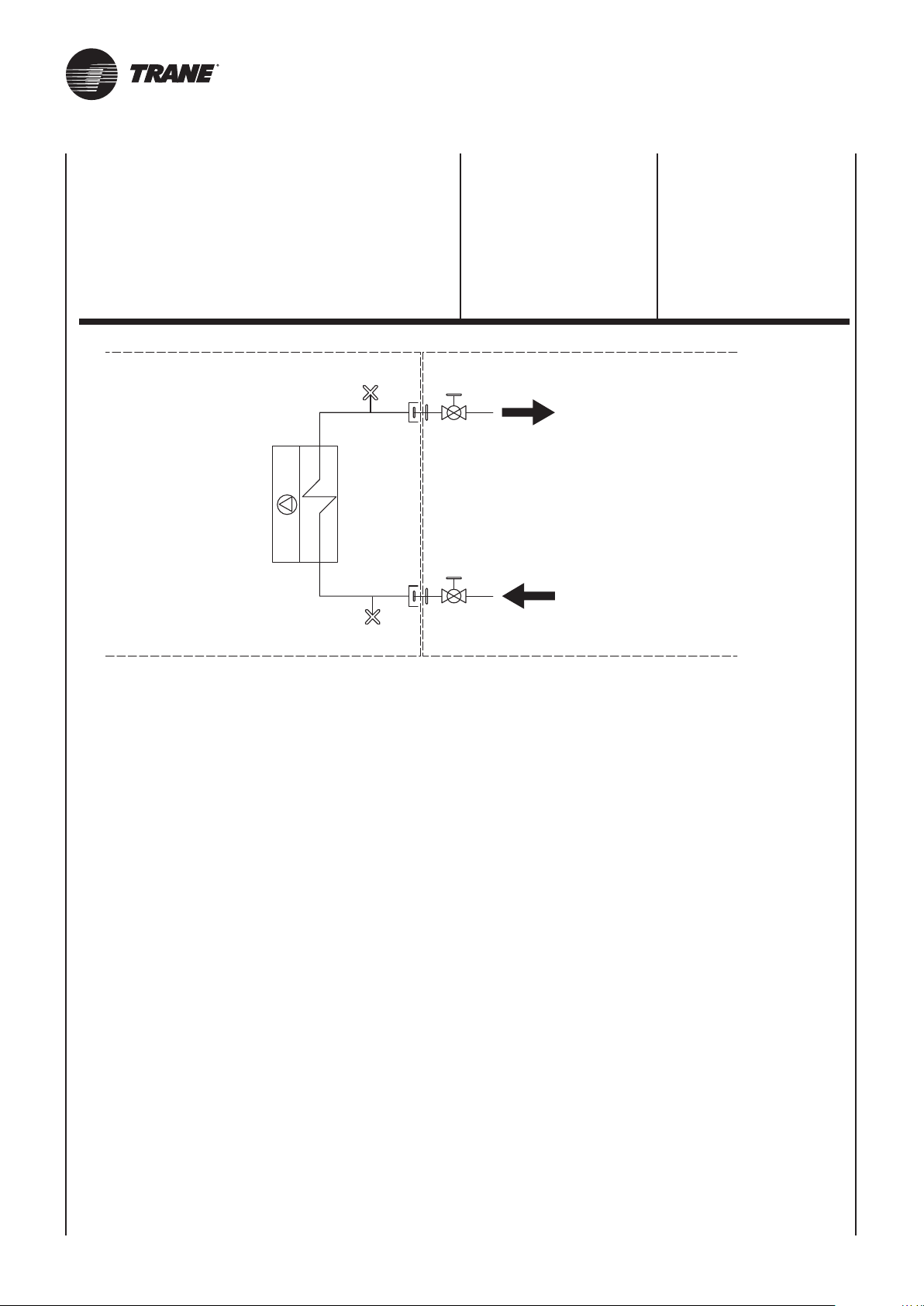
Collegamenti a cura
dell’installatore
Connections carried
out by the installer
Raccordements à
réaliser par l'installateur
Collegamenti
eseguiti in fabbrica
1 Ventilatore
2 Scambiatore di calore
3 Sfiato aria manuale
4 Giunto di collegamento
(fornito a corredo)
5 Valvola
di intercettazione a sfera
5
3
4
Uscita
Uscita
Outlet
Outlet
Sortie
Sortie
1 Fan
2 Heat exchanger
3 Air valve
4 Joint (supplied)
5 Ball shutoff valve
Collegamenti
a cura dell’installatore
Connections
carried out in the factory
Raccordements
effectués en usine
1
2
Entrata
Entrata
Inlet
Inlet
3
4 5
Entrée
Entrée
carried out by the installer
à réaliser par l'installateur
Connections
Raccordements
UNT-SVX036A-XX22
Page 43
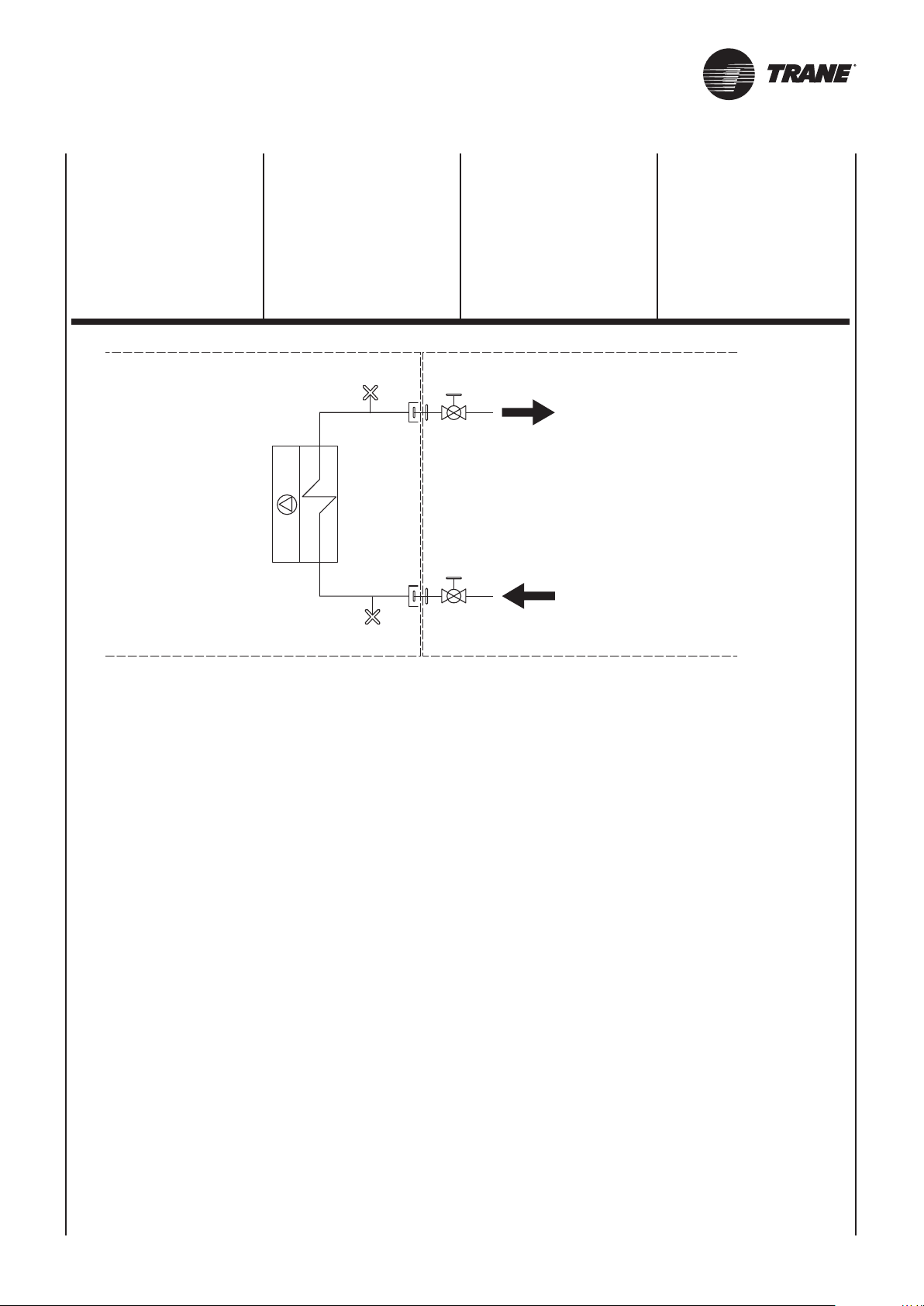
1 Ventilateur
Collegamenti a cura
dell’installatore
Connections carried
out by the installer
Raccordements à
réaliser par l'installateur
2 Échangeur de chaleur
3 Purgeur air manuel
4 Manchette de raccord (fourni)
5 Vanne d’arrêt à bille
Werksseitig
ausgeführte Anschlüsse
1 Ventilator
2 Wärmetauscher
3 Manuelle Entlüftung
4 Anschluss (mitgeliefert)
5 Kugelabsperrventil
3
1 Ventilador
2 Intercambiadores de calor
3 Purgador de aire manual
4 Junta de conexión
(entregada juntocon el aparato)
5 Válvula de corte de esfera
5
4
Austritt
Uscita
Salida
Outlet
Afvoer
Sortie
1 Ventilator
2 Warmtewisselaar
3 Handmatige ontluchting
4 Verbindingselement
(meegeleverd)
5 Kogelafsluitklep
Vom Installateur
auszuführende Anschlüsse
Conexiones
realizadas en fábrica
Aansluitingen
uitgevoerd in de fabriek
1
2
debe realizar el instalador
Conexiones que
Aansluitingen ten laste
van de installateur
Eintritt
Entrata
Entrada
Inlet
3
4 5
Inlaat
Entrée
UNT-SVX036A-XX 22A
Page 44
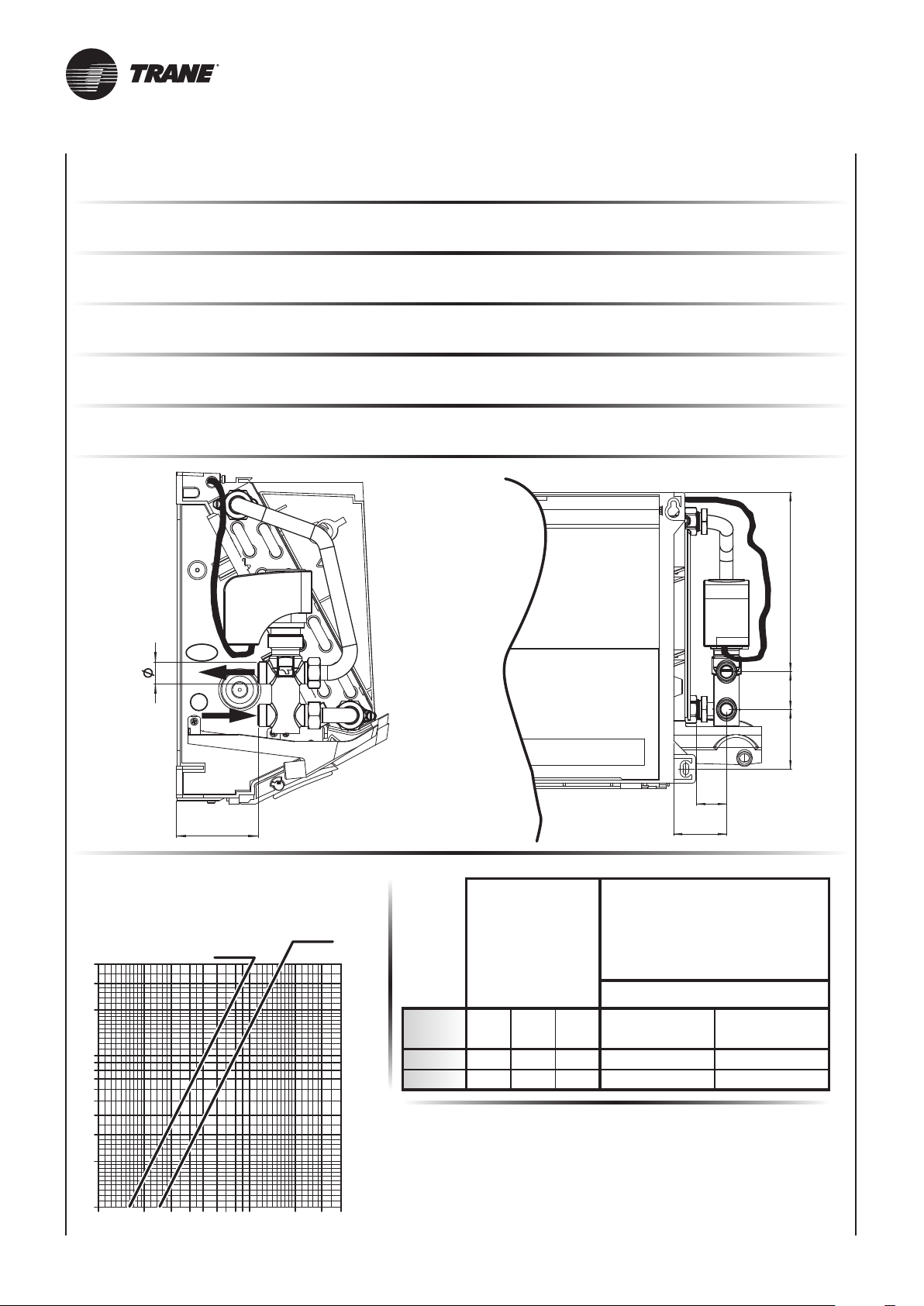
56
190 40
31
63
Kvs 2,5
40
30
20
10
100 200 300 400 600 8001000 2000 3000 4000
Valvola a 3 vie per batteria principale 3WV
Valvola acqua a tre vie ON-OFF 230 V e kit di montaggio (accessorio optional).
3WV main battery 3 way valve
Control valve kit: 3 way valve, ON-OFF, with electric motor and mounting kit (optional).
Vanne pour batterie principale 3WV
Vanne 3 voies (ON-OFF), 230V et kit de montage (option).
3-Wege-Wasserventil für Hauptregister 3WV
3-Wege-Wasserventil ON-OFF 230 V mit elektrischem Motor und Montage KIT (optional).
Válvula para batería principal 3WV
Válvula agua de tres vías ON-OFF, con actuador eléctrico y kit de montaje (opción).
Klep voor hoofdbatterij 3WV
Driewegswaterklep ON-OFF, met elektrische bediening en montagekit (optioneel accessoire).
OUT
IN
77
Non montata
Dp - kPa
Kvs 1,6
Valvola
Valve
Vanne
Wasserventil
Válvula
Not fitted
À monter
Nicht Montiert
No montada
Niet gemonteerd
Klep
Codice - Code - Art. Nr. - Código
9
8
7
6
5
4
3
2
1
Portata acqua (l/h) - Water flow (l/h)
Débit d’eau (l/h) - Wasserdurchflussmenge (l/h)
Caudal de agua (l/h) - Waterdebiet (l/h)
mod.
1 – 2
3 – 4
DN
15
20
(Ø)
1/2” G
3/4” G
Kvs
3 vie - 3 way - 3 voies
3-Wege-Wasserventil
3 vìas - Driewegswaterklep
1,6
2,5
9025321W/H
9025323W/H
2 vie - 2 way - 2 voies
2-Wege-Wasserventil
2 vìas - Tweewegsklep
9025311W/H
9025313W/H
UNT-SVX036A-XX23
Page 45
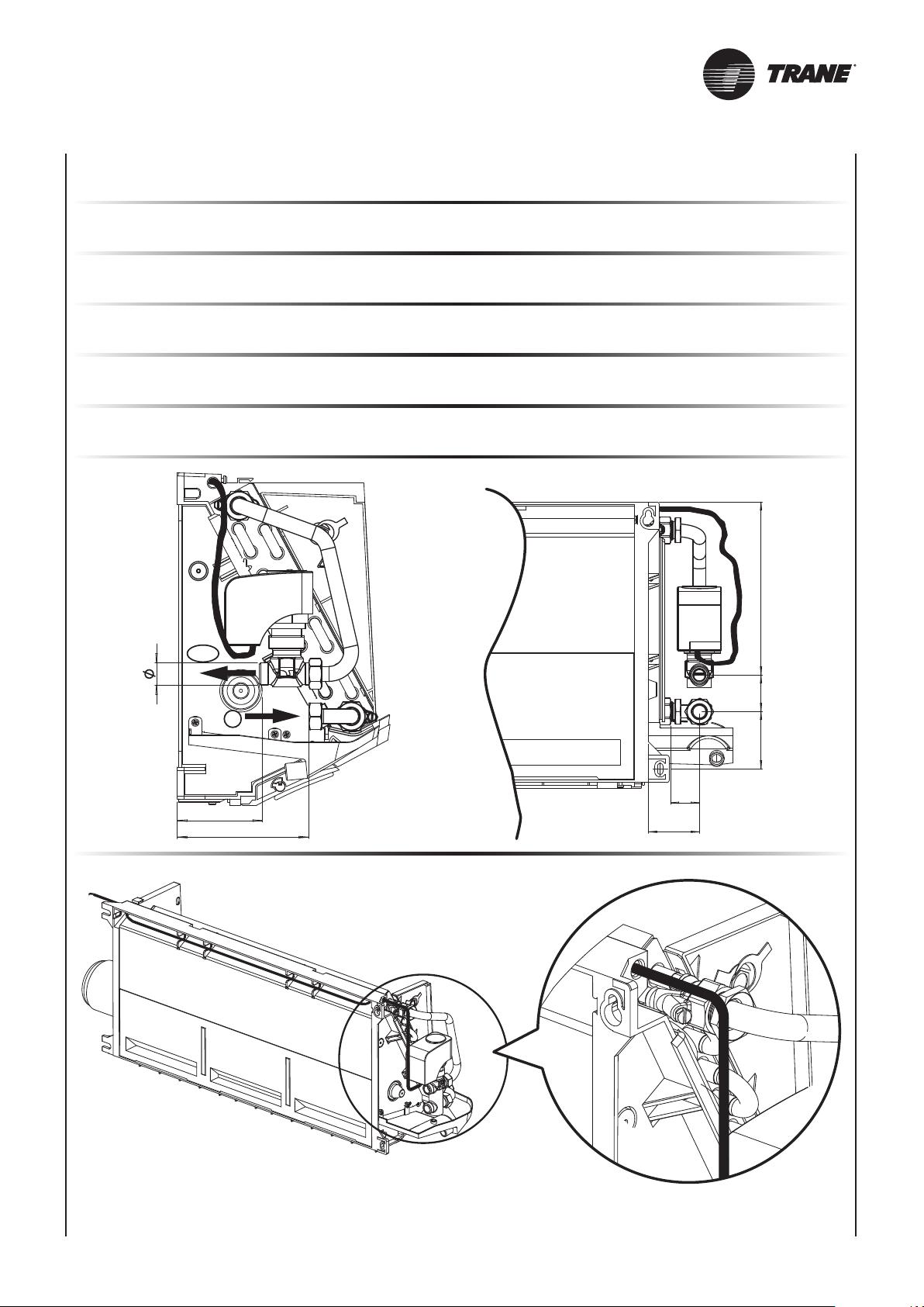
56
190 40
31
63
Valvola a 2 vie per batteria principale 2WV
Valvola a 2 vie ON-OFF 230 V (accessorio optional).
2WV 2 way valve for main coil
Control valve kit: 2 way valve, ON-OFF, with electric motor and mounting kit (optional).
Vanne pour batterie principale 2WV
Vanne 2 voies (ON-OFF), avec servomoteur et kit de montage (option).
2-Wege-Wasserventil für Hauptregister 2WV
2-Wege-Wasserventil ON-OFF 230 V mit elektrischem Motor und Montage KIT (optional).
Válvula para batería principal 2WV
Válvula eléctrica de dos vías ON-OFF, con actuador eléctrico y kit de montaje (opción).
Tweewegshoofdklep voor hoofdbatterij 2WV
Tweewegsklep ON-OFF 230 V (optioneel accessoire).
OUT
IN
77
124
UNT-SVX036A-XX 23A
Page 46
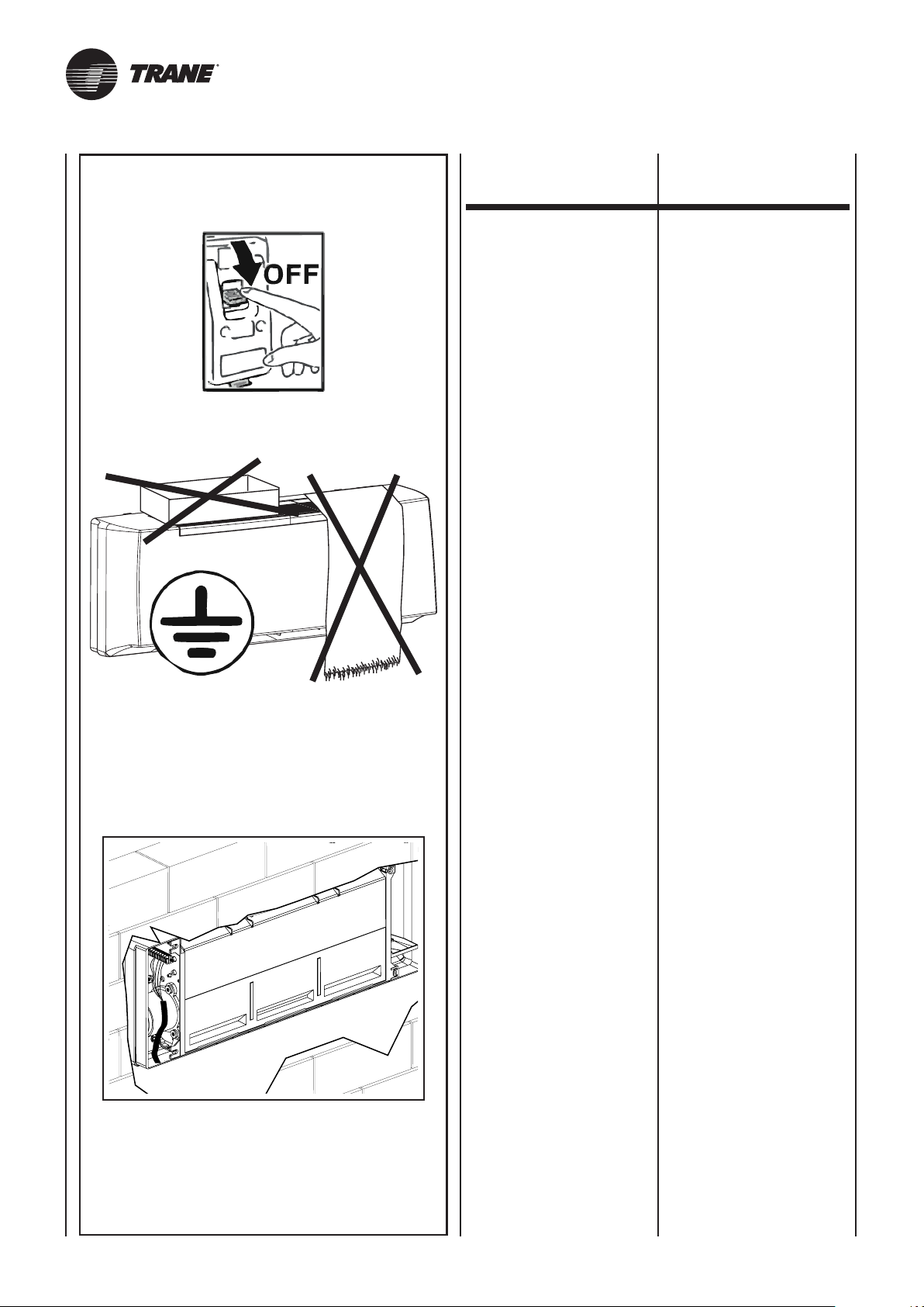
COLLEGAMENTI
ELETTRICI
ELECTRICAL
CONNECTIONS
Prescrizioni generali
• Prima di installare il ventilconvettore verificare che la tensione
nominale di alimentazione sia
di 230V - 50 Hz.
• Assicurarsi che l’impianto elettrico sia adatto ad erogare, oltre
alla corrente di esercizio richie-
sta dal ventilconvettore, anche la
corrente necessaria per alimen tare elettrodomestici ed appa recchi già in uso.
•
Effettuare i collegamenti elettrici
secondo le leggi e le norme na zionali vigenti.
•
A monte dell’unità prevedere un
interruttore onnipolare con di-
stanza minima dei contatti di 3,5
mm.
Occorre sempre effettuare la messa a terra dell’unità.
Togliere sempre l’alimentazione
elettrica prima di accedere alla
macchina.
General instructions
•
Before installing the fan coil, make
sure the rated voltage of the power
supply is 230V - 50 Hz.
• Make sure that, in addition to
supplying the working current
required by the fan coil, the mains
electrical supply is also able to
supply the current necessary
to operate other household
appliances and units.
• Perform electrical connections
in accordance with laws and
regulations in force in the country
concerned.
• Upstream of the unit, fit an
omnipolar switch with minimum
contact distance of 3,5 mm.
The unit must always be earthed.
Always disconnect the electrical
power supply before opening the
unit.
Indicazioni
per il collegamento
L’apparecchio è equipaggiato di
una morsettiera di collegamento
posta sulla fiancata interna, lato
opposto attacchi idraulici. Il collegamento deve essere effettuato
rispettando gli schemi elettrici riportati sul presente libretto.
L’installatore dovrà prevedere l’ingresso dei cavi di collegamento
utilizzando gli accessi previsti, ovvero:
• da muro utilizzando l’apertura
posteriore resa disponibile in
corrispondenza della fiancata.
La morsettiera montata sul ventilconvettore è già predisposta per il
collegamento ai diversi comandi
secondo le indicazioni fornite nella sezione “Comandi e Schemi
elettrici”.
Connection instructions
The unit is fitted with a connection
terminal board on the internal side
panel on the opposite side to the
hydraulic couplings. To connect,
respect the wiring diagrams in this
booklet.
The installer must bring the connecting
wires into the unit through the access
points provided:
• wall-mounted, using the rear
access point corresponding to
the side panel.
The terminal board on the fan coil
is designed for connection to the
various controls following the
instructions provided in the section
“Controls and Electrical Wiring
Diagrams”.
UNT-SVX036A-XX24
Page 47
BRANCHEMENTS
ELECTRIQUES
ELEKTROANSCHLÜSSE
CONEXIONES
ELECTRICAS
ELEKTRISCHE
AANSLUITINGEN
Instructions
• Avant d’installer le ventilo-con vecteur vérifier que la tension
d’alimentation nominale est de
230V - 50Hz.
• S’assurer que la puissance de
l’installation électrique est suffi sante pour fournir le courant de
marche pour le ventilo-convecteur
ainsi que le courant nécessaire
pour alimenter les électroménagers
et les appareils déjà utilisés.
• Effectuer les branchements
électriques selon la législation et
les normes nationales en vigueur.
• En amont de l’unité prévoir un
interrupteur unipolaire avec
distance minimum des contacts
de 3,5 mm.
Il faut toujours effectuer la mise à
la terre de l’unité.
Débrancher toujours la machine
avant d’y accéder.
Allgemeine Anweisungen
• Vor der Installation des Klima konvektors sicherstellen, dass
die nominale Versorgungs spannung 230V - 50 Hz beträgt.
• Sicherstellen, dass die Elektro anlage in der Lage ist, neben
dem Klimakonvektor auch die
anderen Haushaltsgeräte zu
versorgen.
• Die Elektroanschlüsse müssen
gemäß der einschlägigen Gesetze
und Vorschriften hergestellt
werden.
• Dem Gerät einen mehrpoligen
Schalter mit einer Kontaktöffnung
von mindestens 3,5 mm vorschalten.
Das Gerät vorschriftsmäßig erden.
Vor dem Zugriff auf das Geräteinnere stets die Spannungsversorgung unterbrechen.
Prescripciones generales
• Antes de instalar el ventilador
convector verificar que la tensión
nominal de alimentación sea de
230 V - 50 Hz.
•
Asegurarse de que la instalación
eléctrica sea apta para distribuir,
además de la corriente de ejer cicio requerida por el ventilador
convector, la corriente necesaria
para alimentar electrodomésticos
que ya se estuvieran usando.
• Efectuar las conexiones eléctri-
cas de acuerdo con las leyes y
las normativas nacionales vigentes.
•
Prever, más arriba de la unidad,
un interruptor omnipolar con una
distancia mínima de los contac tos de 3,5mm.
Realizar siempre la toma de tierra
de la unidad.
Retirar siempre la corriente eléctrica antes de acceder a la máquina.
Algemene voorschriften
• Alvorens de ventilatorconvector
te installeren, wordt gecontroleerd
of de nominale voedingsspanning
gelijk is aan 230V - 50 Hz.
• Waak erover dat de elektrische
installatie in staat is om, naast
de bedrijfstroom vereist door de
ventilatorconvector, de nodige
energie te leveren voor de voeding
van de reeds in gebruik zijnde
huishoudtoestellen en apparaten.
• De elektrische aansluitingen
uitvoeren volgens de geldende
nationale wetgevingen en normen.
•
Stroomopwaarts van de eenheid
wordt een meerpolige schakelaar
voorzien met een minimale afstand
tussen de polen van 3,5 mm.
De eenheid moet in elk geval worden
uitgerust met een aardaansluiting.
Koppel altijd eerst de elektrische
voeding los alvorens aan het
apparaat te komen.
Indications
pour le raccordement
L’appareil est équipé d’un bornier
de raccordement placé sur le côté
intérieur, du côté opposé aux raccords
hydrauliques. Le raccordement
doit être effectué en respectant
les schémas électriques donnés
dans cette notice.
L’installateur devra prévoir l’entrée
des câbles de raccordement en utilisant les accès prévus, c’est-à-dire:
•
sur le mur en utilisant l’ouverture
postérieure disponible près du
côté.
Le bornier monté sur le ventiloconvecteur est déjà prêt pour la
connexion des différentes commandes selon les instructions fournies
dans la section “Commandes et
Schémas électriques”.
Anleitungen
für den Anschluss
Das Gerät ist mit einer Anschlussklemmleiste ausgestattet, die an
der inneren Seitenwand, gegenüber
den Wasseranschlüssen untergebracht ist. Für den Anschluss
müssen die in dieser Betriebsanleitung enthaltenen Schaltpläne
befolgt werden.
Der Installateur muss die Durchgänge der Anschlusskabel an den
vorhergesehenen Stellen ausführen,
und zwar:
Von der Wand heraus unter
•
Verwendung der hinteren Öffnung
auf Höhe der Seitenwand.
Die am Klimakonvektor montierte
Klemmleiste ist bereits für den
Anschluss der verschiedenen
Steuerungen gemäß den Anleitungen
des Kapitels “Steuerungen und
Schaltpläne” vorbereitet.
Indicaciones
para la conexión
El aparato está equipado con una
caja de bornes de conexión situada en el lateral interno, en el lado
opuesto a las conexiones hidráulicas. La conexión se tiene que
realizar respetando los esquemas
eléctricos que figuran en el presente manual.
El instalador deberá prever la entrada de los cables de conexión
usando los accesos previstos, es
decir:
• desde la pared usando la aper tura posterior disponible en el
lateral.
La caja de bornes montada sobre
el ventilador convector ya está preparada para la conexión a los distintos mandos de acuerdo con las
indicaciones dadas en la sección
“Mandos y Esquemas eléctricos”.
Aanwijzingen
voor de aansluiting
Het apparaat is uitgerust met een
aansluitklemmenbord dat zich
aan de binnenkant bevindt, op de
wand tegenover de hydraulische
aansluitingen. De aansluiting dient
te worden uitgevoerd conform de
schakelschema’s in deze handleiding.
De monteur zal een kabelingang
moeten verwezenlijken door de
toegangen die voorzien werden te
gebruiken, d.w.z.:
aan de muur door de beschikbare
•
opening achteraan te gebruiken,
overeenstemmend met de zijkant.
Het klemmenbord gemonteerd op
de ventilatorconvector is al uitgerust
voor de verbinding met de verschillende
bedieningen volgens de aanwijzingen
in de afdeling “Bedieningen en
elektrische schema’s”.
UNT-SVX036A-XX 24A
Page 48
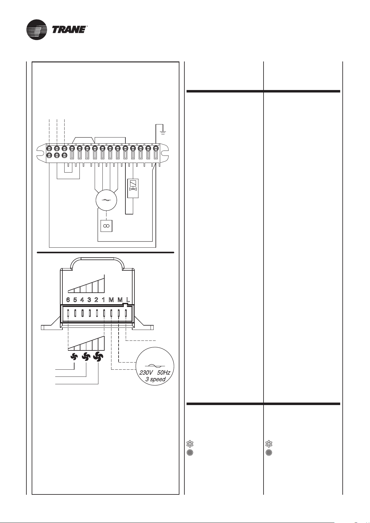
COMANDI
E SCHEMI ELETTRICI
ELECTRICAL
CONTROLS AND
WIRING DIAGRAMS
230Vac
50Hz
PE
L
L
PE
GNYE
N
N
BU
BN
GNYE
54 6
7 98
RD
BU
OG
M
230V
50Hz
GNYE
230Vac
10 121411
BK
I venticonvettori sono dotati di morsettiera alla quale vanno allacciati i
fili provenienti dal comando remoto.
GNYE
Al comando può essere allacciato
un solo ventilconvettore; per otte-
13
15
MFC
E
nere il controllo di più ventilconvettori con un unico comando è
necessario che ogni apparecchio
sia corredato di un selettore di velocità SEL che, su segnale del comando remoto centralizzato, azionerà il proprio apparecchio.
I ventilconvettori dispongono di un
ventilatore con motore a 6 velocità
di cui solo 3 collegate alla morsettiera. Le velocità motore sono ottenute a mezzo di un autotrasformatore. Se si volesse intervenire in
cantiere sulle velocità è sufficiente
spostare il collegamento dei cavi
velocità (rosso, arancio e nero) collegati all’autotrasformatore seguendo la numerazione indicata nello
schema. La connessione nr. 6 dell’autotrasformatore corrisponde
alla velocità 1 della tabella riportata sul catalogo commerciale. A
seguire tutte le altre velocità.
The fan coils have a screw terminal
board to which the wires from the
remote control unit are connected.
Only one fan coil can be connected
to the control unit. To control more
than one fan coil with a single control
unit, each appliance must be fitted
with an SEL speed selector which
controls that particular unit according
to the signal received from the
centralised remote control unit.
The fan coil comes equipped with
a fan that has a 6 speed motor, of
which only 3 are connected to the
terminal board. Motor speeds are
obtained through an auto-transformer.
If wanting to make changes to the
speed on the spot, it is sufficient to
move the speed cable connections
(red, orange and black), that are
connected to the auto-transformer,
following the numbering in the
diagram. The no. 6 connection on
the auto-transformer corresponds
to speed 1 from the table included
in the sales catalogue. All other
speeds follow the same connection
logic.
RD (I)
OG (II)
BK (III)
Speed
6
5
4
3
2
1
(N) BU
M
LEGENDA LEGEND
MFC = Morsettiera
del FAN COIL
M = Motoventilatore
E = Valvola acqua
(IMPIANTO A 2 TUBI)
= Estate - aria fredda
= Inverno - aria calda
GNYE = Giallo/Verde
RD = Rosso = Minima
OG = Arancio = Media
BK = Nero = Massima
BN = Marrone
BU = Blu
MFC = Fan coil
terminal board
M = Fan
E = Water valve
(two tube unit)
= Summer - cold air
= Winter - warm air
GNYE = Yellow/Green
RD = Red = Low
OG = Orange = Medium
BK = Black = High
BN = Brown
BU = Dark blue
UNT-SVX036A-XX25
Page 49
COMMANDES
ET SCHEMAS
ELECTRIQUES
STEUERGERÄTE
UND SCHALTPLÄNE
MANDOS
Y ESQUEMAS
ELÉCTRICOS
BEDIENINGEN
EN ELEKTRISCHE
SCHEMA’S
Les ventilo-convecteurs sont équipés
d’un bornier à vis dans lequel doivent
être raccordés les conducteurs provenant
de la commande à distance.
A la commande ne peut être raccordé
qu’un seul ventilo-convecteur. Pour
obtenir le contrôle de plusieurs
ventilo-convecteurs avec une seule
commande, il faut que chaque
appareil soit équipé d’un sélecteur
de vitesse SEL. Sur signal de la
commande à distance centralisée,
chaque sélecteur actionnera l’appareil sur lequel il est installé.
Les ventilo-convecteurs disposent
d’un ventilateur équipé d’un moteur
à 6 vitesses dont seulement 3 sont
branchés sur le bornier. Les vitesses
du moteur sont obtenues au moyen
d’un autotransformateur. Si l’on
voulait intervenir sur le chantier sur
les vitesses il suffit de déplacer le
branchement des câbles de la
vitesse (rouge, orange et noir) reliés
à l’autotransformateur en suivant la
numération indiquées sur le schéma.
La connexion n.6 de l’autotransformateur
correspond à la vitesse 1 du tableau
mentionné sur le catalogue commercial.
Ainsi de suite pour toutes les autres
vitesses.
Die Gebläsekonvektoren sind mit einem
Schraubklemmenbrett ausgestattet,
in das das am Gerät zu befestigende
Steuerungsklemmenbrett gesteckt
werden muss bzw. an das die von der
Fernsteuerung kommenden Drähte
angeschlossen werden müssen.
An der Steuerung kann nur ein
Gebläsekonvektor angeschlossen
werden. Um mehrere Gebläsekonvektoren mit einer einzigen
Steuerung zu bedienen, muss jedes
Gerät mit einem Drehzahlwählschalter SEL ausgestattet werden,
der auf Signal der zentralisierten
Fernbedienung sein Gerät betätigt.
Die Gebläsekonvektoren besitzen
einen Gebläsemotor mit 6 Drehzahlstufen, von denen nur 3 an die
Klemmleiste angeschlossen sind.
Die Motordrehzahlen werden über
einen Spartransformator geregelt.
Sollen die Drehzahlen vor Ort geändert
werden, genügt es, die Anschlüsse
der am Spartransformator angeschlossenen Drehzahlkabel (rot, orange
und schwarz) zu versetzen und dabei
die im Plan angegebene Nummerierung
zu beachten. Anschluss Nr. 6 des
Spartransformators entspricht
Drehzahl 1 der im Verkaufskatalog
abgedruckten Tabelle. Analog für
alle anderen Drehzahlen.
Los ventiloconvectores están dotados de regleta a la que se conectan
los cables procedentes del mando
a distancia.
Con el control es posible conectar
un solo fan coil. Para lograr controlar varios fan coils mediante un
solo control es preciso que cada
aparato tenga un selector de velocidad, SEL el cual, sobre la base
de la señal del mando a distancia
centralizado, accionará al propio
aparato.
Los ventiloconvectores cuentan
con un ventilador con motor de 6
velocidades, de las cuales sólo 3
conectadas al bornero. Las velocidades del motor se obtienen mediante un autotransformador. Si en
la obra se desea intervenir sobre
las velocidades, es suficiente desplazar la conexión de los cables
de velocidad (rojo, anaranjado y
negro) conectados al autotransformador siguiendo la numeración que
se muestra en el esquema. La conexión nr. 6 del autotransformador
corresponde a la velocidad 1 de la
tabla presente en el catálogo comercial. Y así sucesivamente para
las otras velocidades.
De ventilatorconvectors zijn voorzien
van een klemmenbord met schroeven
waarin het mannelijke klemmenbord
van de bediening dat aan boord
bevestigd moet worden of waaraan de
snoeren die uit de afstandsbediening
komen vastgekoppeld moeten worden.
Aan de bediening kan slechts
één ventilatorconvector worden
gekoppeld; om meerdere ventilatorconvectors te bedienen met één
enkele bediening, moet elk apparaat
uitgerust zijn met een snelheidsschakelaar SEL die, op een signaal
van de centrale afstandsbediening,
zijn aangesloten apparaat in werking
stelt.
De ventilators-convectors beschikken
over een ventilator met motor op
6 snelheden, waarvan slechts 3
aangesloten op het klemmenbord.
De motorsnelheden worden verkregen
door middel van een autotransformator.
Indien men op de werf wenst in te
grijpen op de snelheden, volstaat het
de aansluiting van de snelheidkabels
(rood, oranje en zwart) aangesloten
op de autotransformator te verplaatsen
volgens de nummering aangeduid in
het schema. De aansluiting nr. 6 van
de autotransformator komt overeen met
de snelheid 1 van de tabel vermeld op
de commerciële catalogus. Werk naar
analogie voor alle andere snelheden.
LÉGENDE LEGENDE LEYENDA LEGENDE
MFC = Bornier
du ventilo-convecteur
M = Motoventilateur
E = Vanne à eau
(installation à 2 tubes)
= Eté - air froid
= Hiver - air chaud
GNYE = Juane/Vert
RD = Rouge = Mini
OG = Orange = Moyenne
BK = Noir = Maxi
BN = Marron
BU = Bleu foncé
UNT-SVX036A-XX 25A
MFC = Klemmenbrett
des FAN COIL
M = Motorventilator
E = Wasserventil (Anlage
mit zwei Rohren)
= Sommer - kalte Luft
= Winter - warme Luft
GNYE = Gelb/Grün
RD = Rot = Min
OG = Orange = Med
BK = Schwarz = Max
BN = Braun
BU = Blau
MFC = Borna de conexión
del ventiloconvector
M = Motoventilador
E =
climatización a 2 tubos)
= Verano - aire frio
= Invierno - aire caliente
GNYE = Amarillo/Verde
RD = Rojo = Mínima
OG = Naranja = Media
BK = Negro = Máxima
BN = Marrón
BU = Azul
Válvula agua (sistema de
MFC = Klemmenbord
ventilatorconvector
M = Motorventilator
E = Waterklep
(2-buizige installatie)
= Zomer - koude lucht
= Winter - warme lucht
GNYE = Geel/Groen
RD = Rood = Minima
OG = Oranje = Media
BK = Zwart = Massima
BN = Bruin
BU = Donkerblauw
Page 50
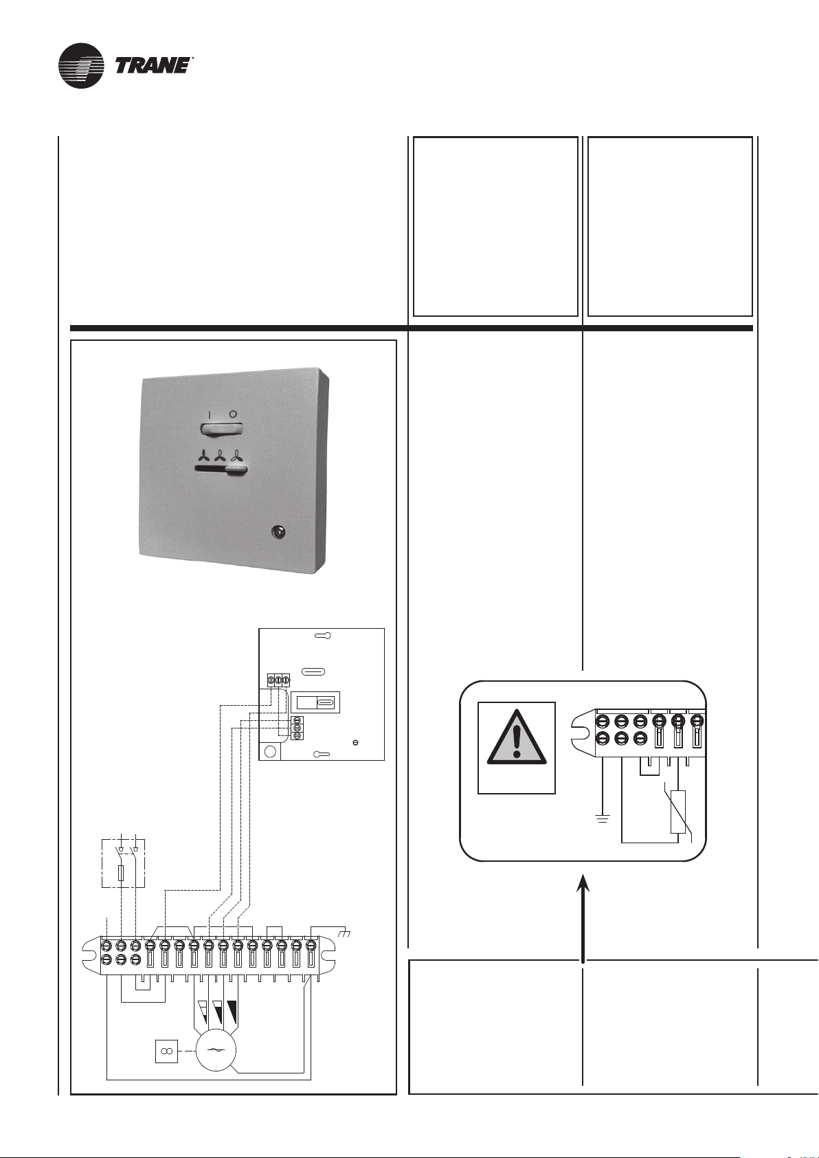
N
L
PE
13
10 121411
15
7 98
54 6
M
230V
50Hz
MFC
OG
BK
RD
BU
BU
BK
GNYE
PE
L
N
Q1
230Vac
50Hz
6
5
4
321
BUBU
BK
GNYE
GNYE
I ventilconvettori
possono essere azionati
con uno dei comandi
montati a parete che,
di seguito, vengono
descritti.
Per l’installazione
e l’utilizzo fare
riferimento al manuale
del comando scelto.
The fan coil
can be operated using
one of the wall controls
described below.
For the installation
and the use read
carefully the manual
of the chosen control.
“M-3V”
type thermostat
Cod. 353400460-001
Pannello comandi
con commutatore per il controllo
della ventilazione con:
- interruttore ON/OFF.
- controllo manuale della velocità
di ventilazione (3 velocità).
MWT
Control panel
with speed switch including:
- ON-OFF switch.
- manual 3 speed switch.
PE
GNYE
“M-3V”
type thermostat
Code 353400460-001
5 6
4
N
L
BU
MWT
VARIANTE
PER L’APPLICAZIONE
DEL TERMOSTATO
DI MINIMA
26
per funzionamento nel ciclo
invernale di riscaldamento)
MWT
(adatto unicamente
VARIANT
FOR APPLICATION
OF MWT
LOW TEMPERATURE
CUT-OUT THERMOSTAT
(suitable
for winter heating mode
operation only)
UNT-SVX036A-XX
Page 51
Les ventilo-convecteurs
peuvent
être actionnés avec
l’une des commandes
murals
décrites ci-après.
Pour l’installation
et l’utilisation
lire attentivement
le manuel de
la commande choisie.
Die Gebläsekonvektoren
können mit
einer der nachstehend
beschriebenen
Wandsteuerungen
bedient werden.
Für die Installation
und den Gebrauch
ist das Handbuch der
ausgewählten Steuerung
sorgfältig zu lesen.
Los fan coils pueden
ser accionados
con uno de los controles
de pared
que se describen
a continuación.
Para la instalación
y la utilización leer
atentamente el manual
del mando elegido.
De ventilatorconvectors
kunnen geactiveerd
worden met één van de
hieronder beschreven
bedieningen die op de
muur gemonteerd zijn.
Voor het installeren
en het gebruik dient
u de handleiding van de
gekozen bediening te
raadplegen.
“M-3V”
type thermostat
Code 353400460-001
Boîtier de commande
avec commutateur de vitesse
avec:
- interrupteur ON-OFF.
- commutateur 3 vitesses
(manuel).
“M-3V”
type thermostat
Art. Nr. 353400460-001
Bedientafel mit Umschaltung
für die Kontrolle des Ventilators
mit:
- ON-OFF Schalter.
- manuelle Umschaltung
zwischen den
3 Ventilatordrehzahlen.
“M-3V”
type thermostat
Cód. 353400460-001
Panel de mandos
con conmutador para el control
del ventilador con:
- interruptor ON-OFF.
- conmutación manual
de las 3 velocidades
del ventilador.
“M-3V”
type thermostat
Code 353400460-001
Bedieningspaneel met
omschakelaar voor de controle
van de ventilatie met:
- schakelaar AAN/UIT.
- handmatige controle
van de ventilatiesnelheid
(3 snelheden).
VARIANTE
POUR L’APPLICATION
DU THERMOSTAT
DE TEMPÉRATURE MINIMUM
(MWT)
(adaptée uniquement
au fonctionnement en cycle
hiver de chauffage)
UNT-SVX036A-XX 26A
DES MINDESTTEMPERATUR-
VARIANTE
FÜR DIE ANBRINGUNG
THERMOSTATS
MWT
(geeignet ausschließlich
für den Heizbetrieb
im Winter)
VARIANTE
PARA LA APLICACIÓN
DEL TERMOSTATO
DE MÍNIMA
(MWT)
(apto sólo para
el funcionamiento en el ciclo
invernal de calefacción)
VARIANTE
VOOR DE TOEPASSING
VAN DE UITSCHAKEL-
THERMOSTAAT
MWT
(enkel geschikt om te verwarmen
in de wintercyclus)
Page 52
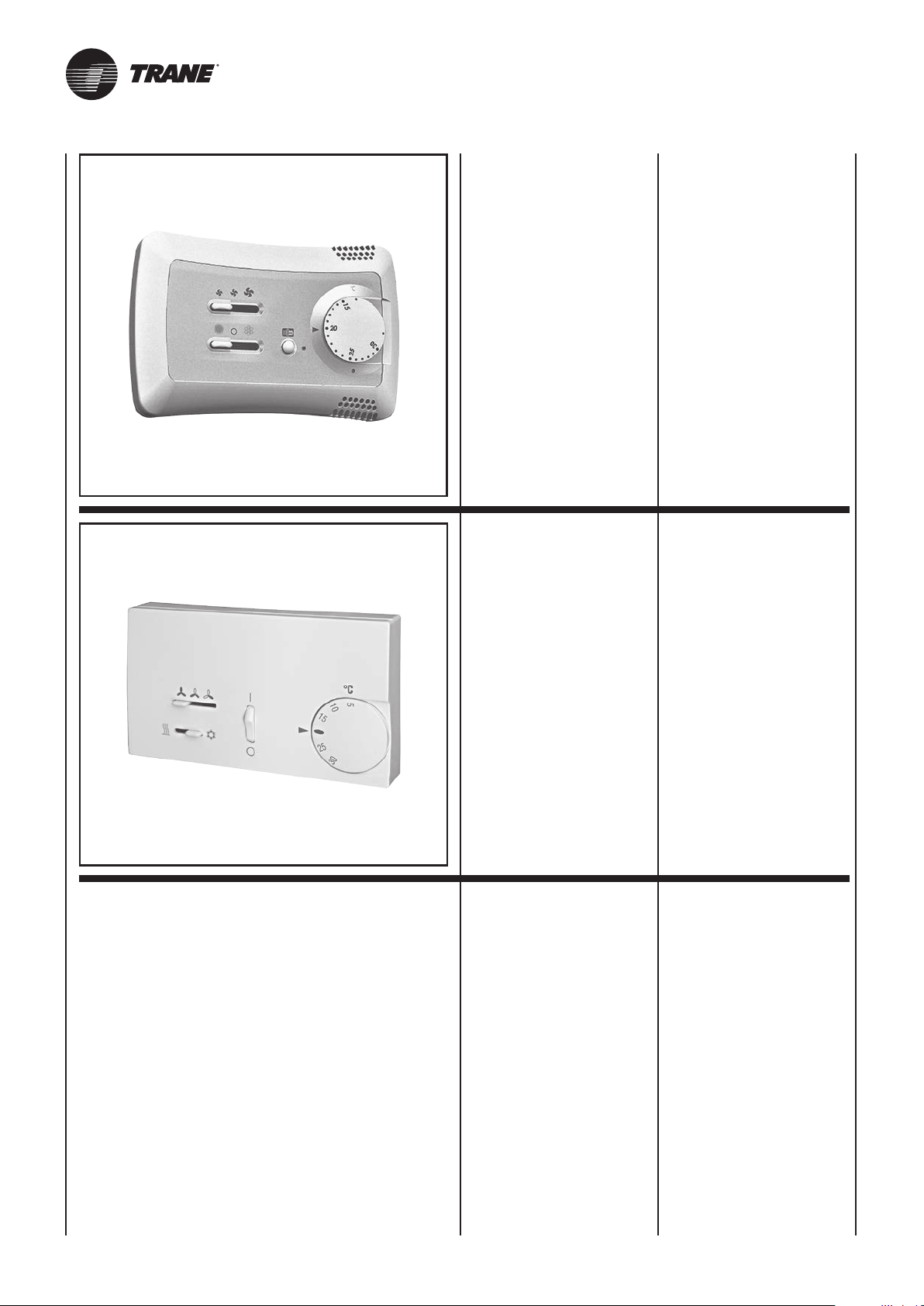
“T-REM”
type thermostat
Cod. 353400470-001
Pannello comandi
con termostato elettronico
per impianti a 2 e 4 tubi
e resistenza elettrica:
- controllo manuale della velocità
di ventilazione (3 velocità).
- controllo termostatico
del ventilatore o di 1-2 valvole.
- cambio stagionale
manuale o automatico.
“T-REM”
type thermostat
Code 353400470-001
Control panel
with electronic room thermostat
for 2-4 tube installations
and electric heater:
- manual 3 speed switch.
- electronic room thermostat
for fan control
or for the control of 1-2 valves.
- manual/automatic
Summer/Winter switch.
- sonda di minima T3
(accessorio).
“T2T”
type thermostat
Cod. 35169888-001
Pannello comandi
con termostato elettronico
per impianti a 2 tubi:
- controllo manuale della velocità
di ventilazione (3 velocità).
- controllo termostatico
del ventilatore o di 1 valvola.
- cambio stagionale manuale.
- optional low temperature
cut-out thermostat T3.
“T-REM”
type thermostat
Code 35169888-001
Control panel
with electronic room thermostat
for 2 tube installations:
- manual 3 speed switch.
- electronic room thermostat
for fan control
or for the control of 1 valve.
- manual Summer/Winter switch.
27
UNT-SVX036A-XX
Page 53
“T-REM”
type thermostat
Code 353400470-001
Boîtier de commande
avec thermostat électronique
pour installations à 2-4 tubes
et resistance électrique:
- commutateur 3 vitesses
(manuel).
- controle thermostatique du
ventilateur ou de 1-2 vannes.
- commutateur
manuel/automatique été/hiver.
- optionnel thermostat de
limitation basse de soufflage T3.
“T-REM”
type thermostat
Art. Nr. 353400470-001
Bedientafel
mit elektronischem Thermostat
für Anlagen mit 2-4 Leitern
und elektrischer Widerstand:
-
manuelle Umschaltung zwischen
den 3 Ventilatordrehzahlen.
- Temperaturregelung
vom Ventilator
oder von 1-2 Wasserventilen.
- manuelle/automatische
Umschaltung des saisonalen
Zyklus (Sommer - Winter).
- optionaler Mindesttemperatur fühler T3.
“T-REM”
type thermostat
Cód. 353400470-001
Panel de mandos
con termostato electrónico
para instalaciones con 2-4 tubos
y resistencia eléctrica:
- conmutación manual de las
3 velocidades del ventilador.
- control termostático
del ventilador o de 1-2 válvulas.
-
conmutación manual/automática
verano/invierno.
- sonda de mínima T3
(opcional).
“T-REM”
type thermostat
Code 353400470-001
Bedieningspaneel met
elektronische thermostaat voor
installaties met 2 en met 4 leidingen
en elektrische weerstand:
- handmatige controle van de
ventilatiesnelheid (3 snelheden).
- thermostatische controle
van de ventilator
of van 1-2 kleppen.
- handmatige of automatische
seizoenomschakeling.
- uitschakelthermostaat T3
(accessoire).
“T-REM”
type thermostat
Code 35169888-001
Boîtier de commande
avec thermostat électronique
pour installations à 2 tubes:
- commutateur 3 vitesses
(manuel).
- controle thermostatique
du ventilateur or de 1 vanne.
- commutateur manuel été/hiver.
“T-REM”
type thermostat
Art. Nr. 35169888-001
Bedientafel
mit elektronischem Thermostat
für Anlagen mit 2 Leitern:
- manuelle Umschaltung zwischen
den 3 Ventilatordrehzahlen.
- Temperaturregelung
vom Ventilator
oder von 1 Wasserventil.
- manuelle Umschaltung
des saisonalen Zyklus
(Sommer - Winter).
“T-REM”
type thermostat
Cód. 35169888-001
Panel de mandos
con termostato electrónico
para instalaciones con 2 tubos:
- conmutación manual de las
3 velocidades del ventilador.
- control termostático
del ventilador o de 1 válvula.
- conmutación
manual verano/invierno.
“T-REM”
type thermostat
Code 35169888-001
Bedieningspaneel
met elektronische thermostaat
voor installaties met 2 leidingen:
- handmatige controle van de
ventilatiesnelheid (3 snelheden).
- thermostatische controle
van de ventilator of van 1 klep.
- handmatige
seizoenomschakeling.
UNT-SVX036A-XX
27A
Page 54
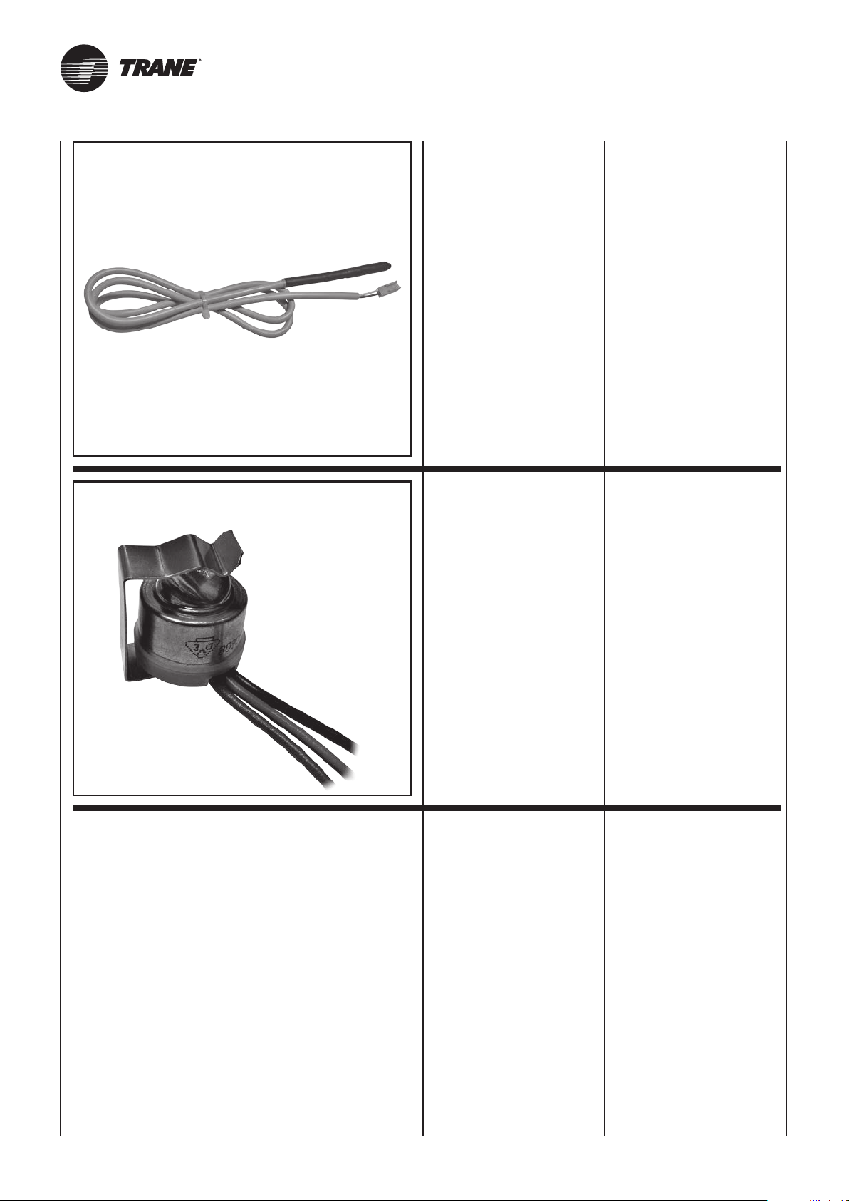
T3
SONDA DI MINIMA
T3
Cod. 35169496-001
Da posizionare fra le alette della
batteria di scambio termico.
T3 LOW TEMPERATURE
CUT-OUT THERMOSTAT
Code 35169496-001
Position between the fins of the
heat exchanger coil.
B8
Abbinabile ai comandi:
T-REM.
Per il collegamento al comando, il
cavo della sonda T3 deve essere
separato dai conduttori di potenza.
Durante il funzionamento invernale
arresta l’elettroventilatore quando
la temperatura dell’acqua è inferiore ai 28°C, e lo fa ripartire quando
questa raggiunge i 33°C.
Change-Over
B8
Cod. 35167863-001
Cambio stagionale automatico da
posizionare in contatto con il tubo
di alimentazione.
Solamente per impianti a due tubi
(non utilizzabile con la valvola a
2 vie).
Abbinabile ai comandi: T-REM.
For use with control units:
T-REM.
When connecting the control, the
T3 probe cable must be separated
from the power supply wires.
During winter operation stops the
fan when the water temperature drops
below 28°C and starts it up again
when the temperature reaches 33°C.
Change-Over sensor
B8
Code 35167863-001
Automatic summer/winter switch to
be installed in contact with the water
circuit (for 2-tube installations only).
Only for 2 pipe installations (not
to be used with 2 way valve).
For use with control units: T-REM.
28
UNT-SVX036A-XX
Page 55
SONDE DE TEMPÉRATURE
MINIMUM T3
Code 35169496-001
Doit être placée entre les ailettes
de la batterie d’échange thermique.
MINDESTTEMPERATUR-
FÜHLER T3
Art. Nr. 35169496-001
Diese Sonde wird zwischen den
Leitlamellen der WärmetauscherBatterie angebracht.
SONDA DE MÍNIMA
T3
Cód. 35169496-001
A colocar entre las aletas de la
batería de intercambio térmico.
UITSCHAKEL-
THERMOSTAAT T3
Code 35169496-001
Te plaatsen tussen de ribben van
de warmtewisselaars.
Associable aux commandes:
T-REM.
Pour le raccordement à la commande,
le câble de la sonde T3 doit être
séparé des câbles de puissance.
Pendant le fonctionnement hiver
arrête le ventilateur quand la température de l’eau est inférieure à
28°C et le fait repartir quand elle
atteint 33°C.
Change-Over
B8
Code 35167863-001
Commutateur saisonnier automatique à installer en contact avec le
tube d’alimentation.
Uniquement pour installations à
2 tubes (non compatible avec la
vanne à 2 voies).
Associable aux commandes:
T-REM.
Kombinierbar mit den Steuerungen:
T-REM.
Für den Anschluss an die Steuerung
muss das Kabel des Fühlers T3 von
den Leistungsleitungen getrennt sein.
Der Fühler hält bei Winterbetrieb den
Ventilator an, wenn die Temperatur
des Wassers unter 28°C ist, und
setzt ihn wieder in Betrieb, wenn
sie 33°C erreicht hat.
Combinable con los
dispositivos de accionamiento:
T-REM.
Para la conexión al mando, el cable
de la sonda T3 debe separarse
de los conductores de potencia.
Durante el funcionamiento en invierno para el electroventilador cuando
la temperatura del agua es inferior
a 28°C y lo vuelve a poner en marcha cuando esta alcanza los 33°C.
Change-Over
B8
Art. Nr. 35167863-001
Automatischer Saisonwechsel, in
Kontakt mit dem Wasserrohr zu
installieren.
Nur für 2-Leiter-Anlagen (nicht
verwendbar mit dem 2-Wege-Ventil).
Kombinierbar mit den Steuerungen:
T-REM.
Cambio estacional automático que
se tiene que colocar en contacto
con el conduco de alimentación.
Solo con instalaciones con 2 tubos
(no se puede utilizar con la válvula
de dos vías).
Combinable con los dispositivos
de accionamiento: T-REM.
Change-Over
B8
Cód. 35167863-001
Combinerend met de bedieningen:
T-REM.
Voor de aansluiting op de besturing,
moet de kabel van de T3-sonde
gescheiden zijn van de stroomdraden.
Tijdens de wintercyclus schakelt hij de
elektroventilator uit als de temperatuur
van het water minder dan 28°C
bedraagt, en opnieuw inschakelt
als de temperatuur 33°C bereikt.
B8
Change-Over sensor
Code 35167863-001
Automatische seizoenwisseling die
in contact met de voedingsleiding
moet worden geplaatst.
Enkel voor installaties met twee
leidingen (not to be used with 2
way valve).
Combinerend met de bedieningen:
T-REM.
UNT-SVX036A-XX 28A
Page 56
RESISTENZA
ELETTRICA
EH
EH
ELECTRICAL
HEATER
Sono disponibili apparecchi
con resistenza elettrica
nella configurazione 2 tubi
più resistenza.
La resistenza viene gestita
al posto della valvola batteria
acqua calda.
Le resistenze sono del tipo
corazzato ad elementi inseriti
all’interno del pacco batteria
e devono quindi essere fornite
solo su prodotti specifici
montati in fabbrica.
L’alimentazione
delle resistenze elettriche
montate sugli apparecchi
è di tipo monofase 230 Volt.
La resistenza è corredata
di termostato di sicurezza atto
a prevenire surriscaldamenti
dell’apparecchio.
Al comando
può essere allacciato un solo
ventilconvettore.
2 pipe models are available
with electrical heater
that is controlled in place
of the heating battery valve.
The electrical heater
is controlled in place of the hot
water valve.
The heater is hermetically
sealed and supplied
inside the battery pipes
and therefore can be only
factory mounted.
The electrical heaters
of the units are for single phase
230V supply.
The heater is fitted
with a safety thermostat
to prevent the appliance from
overheating.
Only one fan coil can be
connected to the control unit.
modello / model / modèle
Potenza nominale installata
Nominal installed power
Puissance nominale installée
Tensione nominale di alimentazione
Nominal power voltage
Tension nominale d’alimentation
Num. e sezione dei cavi di collegamento
Number and section of connecting wires
Nombre et section des câbles de raccordement
Corrente assorbita max.
Current input
Courant absorbé
Fusibile consigliato (Tipo gG) per la protezione da sovraccarico
Recommended fuse (Typo gG) for overload protection
Fusible conseillé (Type gG) pour la protection de surcharge
WFS–EH 1 – 2
1000 Watt
230V
~
3 x 1,5mm
Per i collegamenti elettrici
di alimentazione dell’unità
e delle resistenze elettriche
utilizzare cavo H07 RN-F.
Assicurarsi che il collegamento
alla rete elettrica sia effettuato
attraverso un interruttore
onnipolare con distanza minima
dei contatti di almeno 3,5 mm.
2
4,5 A
6 A
WFS–EH 3 – 4
1500 Watt
230V
~
3 x 1,5mm
For the power supply
connections to the unit
and the electric heaters,
use H07 RN-F cable.
Check that an omnipolar switch
with a minimum contact distance
of 3,5 mm is used for
the connection to the mains
power supply.
2
7 A
8 A
UNT-SVX036A-XX29
Page 57
BATTERIE
ÉLECTRIQUE
EH
ELEKTROHEIZREGISTER
EH
BATERÍA
ELÉCTRICA
EH
ELEKTRISCHE
BATTERIJ
EH
Sont disponibles les appareils
ayant une résistance électrique
dans la configuration 2 tuyaux
plus résistance.
La résistance
est gérée à la place de la vanne
batterie d’eau chaude.
Les résistances
du type blindées sont
proposées sous forme d’un kit
spécialement monté d’usine.
L’alimentation
des résistances électriques
montées sur les appareils
est de type monophasé 230 Volt.
La résistance est munie
d’un thermostat de sécurité
permettant d’éviter
les surchauffes de l’appareil.
A la commande
ne peut être raccordé qu’un
seul ventilo-convecteur.
Die beinhaltet Geräte
mit Elektroheizregister in der
Konfiguration 2-Leiter plus
Heizregister.
Das Heizregister
wird anstelle des Ventils des
Warmwasserregisters verwaltet.
Die gussgekapselten
Heizregister sind mit in das
Innere des Registers eingefügten
Elementen und können
folglich nur an spezifischen,
werkseitig montierten Produkten
geliefert werden.
Die einphasige Versorgung
der an den Geräten
montierten Heizregister
erfolgt mit 230 Volt.
Die Heizung ist mit
einem Sicherheitsthermostat
ausgerüstet, um das Gerät vor
Überhitzung zu schützen.
An der Steuerung
kann nur ein Gebläsekonvektor
angeschlossen werden.
En la serie hay disponibles
aparatos con resistencia eléctrica
con la configuración 2 tubos
más resistencia.
La resistencia se utiliza
en lugar de la válvula batería
agua caliente.
Las resistencias son del
tipo acorazado con elementos
insertos dentro del paquete
batería y deben por lo tanto
suministrarse cólo en productos
específicos montados en fábrica.
La alimentación de las
resistencias eléctricas montadas
en los aparatos es
del tipo monofásico 230 Volt.
La resistencia incorpora
un termóstato de seguridad
destinado a prevenir
el recalentamiento del aparato.
Con el dispositivo
de accionamiento es posible
conectar un solo ventiloconvector.
In de apparaten beschikbaar
met een elektrische weerstand
in de configuratie 2 leidingen
plus weerstand.
De weerstand wordt gestuurd
in plaats van de klep van
de batterij voor het warm water.
De weerstanden zijn gekoppeld
aan elementen die zich in het
batterijblok bevinden en worden
dus alleen geleverd
met specifieke in de fabriek
gemonteerde producten.
De voeding van
de elektrische weerstanden
gemonteerd op de apparaten
is eenfasig 230 Volt.
De weerstand is voorzien
van een veiligheidsthermostaat,
om oververhitting
van het apparaat te voorkomen.
Op de bediening kan
één enkele luchtverhitter
aangesloten worden.
modell / modelo / model
Installierte Nennleistung
Potencia nominal instalada
Nominaal geïnstalleerd vermogen
Versorgungsnennspannung
Tensión nominal de alimentación
Nominale toevoerspanning
Zahl und Größe der Verbindungskabel
Número y sección de los cables de conexión
Aantal en doorsnede van de aansluitkabels
Max. Stromaufnahme
Máxima corriente absorbida
Max. opgenomen vermogen
Zum Schutz vor Überlastung empfohlene Sicherung (Typ gG)
Fusible aconsejado (Tipo gG) para la protección contra la sobrecarga
Aanbevolen zekering (Type gG) ter bescherming tegen overbelasting
Pour les branchements
électriques de l’unité et des
résistances électriques utiliser
un câble H07 RN-F.
L’appareil doit être raccordé
au secteur au moyen
d’un interrupteur omnipolaire
avec un écartement
des contacts supérieur à 3,5 mm.
Für die Elektroanschlüsse
des Geräts und der Heizregister
ein Kabel des Typs H07 RN-F
verwenden.
Sicherstellen, dass der
Anschluss an das Stromnetz mit
Hilfe eines allpoligen Schalters
mit einer Kontakt-öffnung von
mindestens 3,5 mm hergestellt ist.
WFS–EH 1 – 2
1000 Watt
230V
~
3 x 1,5mm
Para las conexiones eléctricas
de alimentación de la unidad
y de las resistencias eléctricas
usar cable H07 RN-F.
Cerciorarse de que la conexión
a la red eléctrica se realice
a travñes de un interruptor
omnipolar con distancia mínima
de los contactos de 3,5 mm.
2
4,5 A
6 A
WFS–EH 3 – 4
1500 Watt
230V
~
3 x 1,5mm
Voor de aansluiting
van de elektrische voeding
van de eenheid en de elektrische
weerstanden, wordt een kabel
H07 RN-F gebruikt.
Zorg ervoor dat de aansluiting
op het elektriciteitsnet uitgevoerd
wordt met een veelpolige
schakelaar en een minimale
afstand tussen de polen van 3,5 mm.
2
7 A
8 A
UNT-SVX036A-XX 29A
Page 58
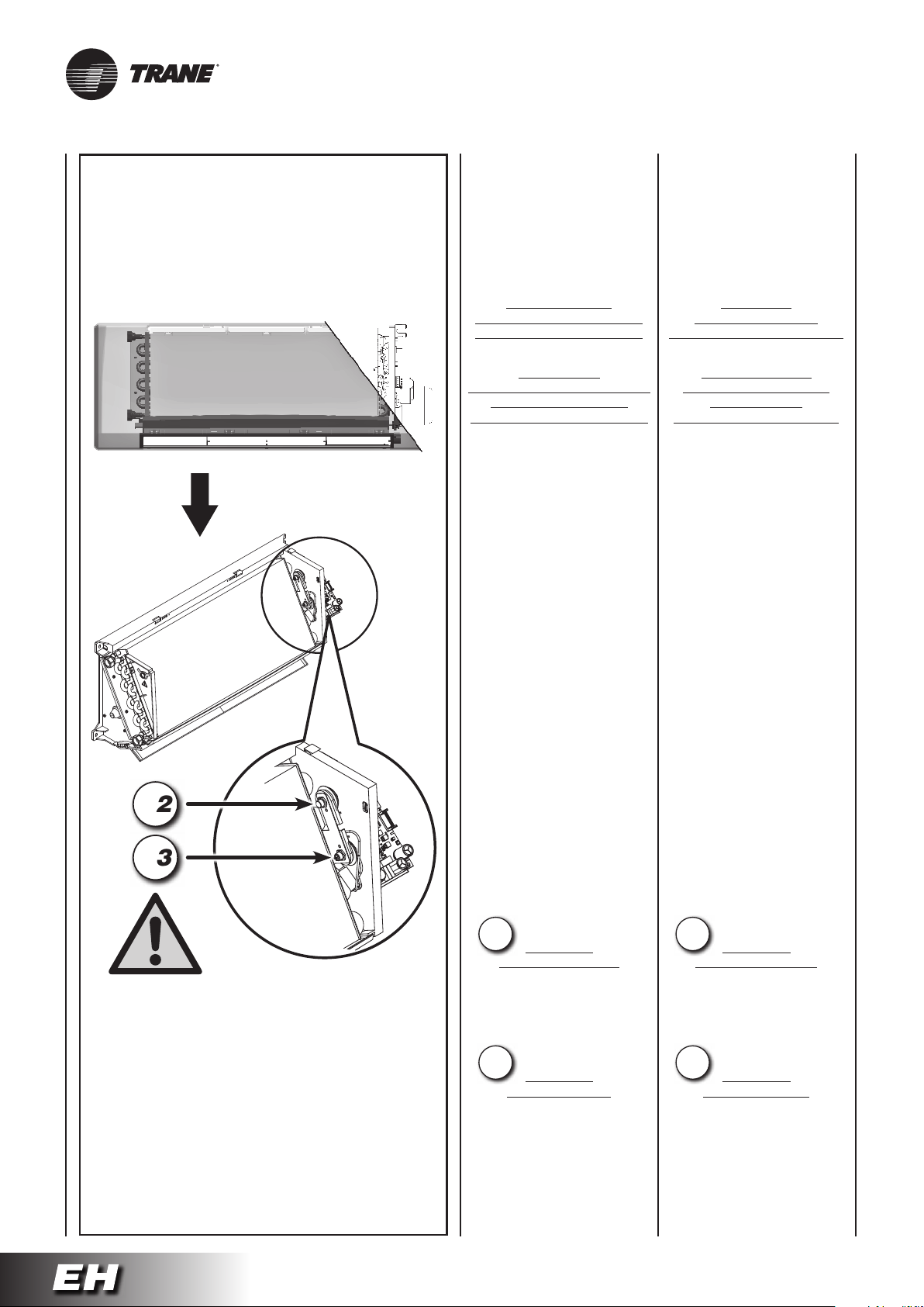
Avvertenze
In fase di prima installazione,
prima di attivare
le resistenze elettriche verificare
che il ventilatore funzioni
correttamente a tutte e tre
le velocità previste.
Warnings
When first installing
the appliance, before starting
the electric heaters, check
that the fan on the unit
is working correctly at all three
speeds envisaged.
B2
B3
Non chiudere mai
le alette di mandata dell’aria
o ostruire i passaggi interni.
Nelle versioni
con resistenza non è possibile
utilizzare la sonda TME
di minima temperatura acqua.
Termostati di sicurezza
La batteria elettrica
è equipaggiata con un sistema
di protezione
contro le sovratemperature.
L’apparecchiatura
è dotata di due termostati
di sicurezza:
- Un termostato
a riarmo manuale;
- Un termostato
a riarmo automatico.
Nel caso di intervento
del termostato di sicurezza
individuare sempre le cause
che ne hanno provocato
l’intervento prima di rialimentare
le resistenze elettriche
dell’apparecchio.
Nel caso non si riesca
ad individuare la causa
dell’intervento della protezione,
contattare il personale tecnico
qualificato.
Never close
the air outlet louvers
or block the inside passages.
The TME minimum
water temperature probe
cannot be used
on the versions with heater.
Safety thermostats
The electric coil
is fitted with a system
for protecting against excess
temperature.
The appliance
is fitted with two safety
thermostats:
- one thermostat
with manual reset;
- one thermostat
with automatic reset.
If the safety thermostat trips,
always identify the causes
before restarting the electric
heaters on the appliance.
If the problem that caused
the activation of the thermostat
cannot be found, contact
qualified technical personnel.
POSIZIONE DEL PULSANTE DI RIARMO
DEL TERMOSTATO DI SICUREZZA
POSITION
OF THE SAFETY THERMOSTAT RESET BUTTON
POSITION DE LA TOUCHE DE RÉARMEMENT
DU THERMOSTAT DE SÉCURITÉ
POSITION DER RESETTASTE
DES SICHERHEITSTHERMOSTATS
POSICIÓN DEL PULSADOR DE REARME
DEL TERMOSTATO DE SEGURIDAD
POSITIE VAN DE RESETKNOP
VAN DE VEILIGHEIDSTHERMOSTAAT
B2 B2
Termostato
a riarmo automatico
L’apparecchio è dotato
di un termostato di sicurezza
a riarmo automatico
posizionato nella batteria.
B3 B3
Termostato
a riarmo manuale
L’apparecchio è dotato
di un termostato di sicurezza
a riarmo manuale
posizionato nella batteria.
Il riarmo del termostato
viene effettuato premendo
il tasto evidenziato in figura.
Thermostat
with automatic reset
The appliance is fitted
with a safety thermostat,
featuring automatic reset,
installed in the coil.
Thermostat
with manual reset
The appliance is fitted
with a safety thermostat,
with manual reset,
installed in the coil.
The thermostat is reset
by pressing the button
highlighted in the figure.
UNT-SVX036A-XX30
Page 59
Attention
Lors de la première installation,
avant d’allumer les résistances
électriques, vérifier que le
ventilateur du ventilo-convecteur
fonctionne correctement
aux trois vitesses prévues.
Ne jamais fermer
les volets de soufflage
de l’air ou boucher
les passages intérieurs.
Dans les versions
à résistance il n’est pas
possible d’utiliser
la sonde TME
de température minimale eau.
Hinweise
Bevor die Heizregister während
der Erstinstallation aktiviert werden,
muss sichergestellt werden,
dass der Ventilator des Klimakonvektors bei allen drei
vorgesehenen Drehzahlen
korrekt funktioniert.
Die Luftklappen
weder verschließen, noch den
Durchfluss behindern.
Bei den Versionen
mit Heizregister kann der
Mindesttemperaturfühler TME
nicht verwendet werden.
Advertencias
En la primera instalación,
antes de activar las resistencia
eléctricas verificar que
el ventilador del funcione
correctamente a todas las 3
velocidades previstas.
No cerrar nunca
las aletas de entrada del aire
o obstruir los pasos internos.
En las versiones
con resistencia no se puede
usar la sonda TME de mínima
temperatura del agua.
Voorschriften
Bij de eerste installatie
en alvorens de elektrische
weerstanden in te schakelen,
controleer of de ventilator
van correct werkt op de drie
voorziene snelheden.
Sluit nooit de vleugels
van de luchtaanvoer
en belemmer de interne
doorgang niet.
In de versies met weerstand
is het niet mogelijk
gebruik te maken
van de uitschakelthemostaat
TME voor de water.
Thermostat de sécurité
La batterie électrique
est équipée d’un système
de protection
contre les surtempératures.
L’appareil
est muni de deux thermostats
de sécurité:
- un thermostat
à réarmement manuel;
- un thermostat
à réarmement automatique.
En cas de déclenchement
du thermostat de sécurité
en rechercher la cause
avant d’alimenter de nouveau
les résistances électriques
de l’appareil.
S’il n’est pas possible
de trouver la cause qui
a déclenché la protection,
contacter un technicien qualifié.
Sicherheitsthermostate
Das Elektroregister ist
mit einem Sicherungssystem
gegen Überhitzung ausgestattet.
Das Gerät ist mit
zwei Sicherheits- thermostaten
ausgestattet:
- Ein Thermostat
mit manuellem Reset;
- Ein Thermostat
mit automatischem Reset.
Wenn der Sicherheitsthermostatausgelöst wurde,
muss immer die Ursache
herausgefunden werden, bevor
die Heizwiderstände
des Gerätserneut unter
Spannung gesetzt werden.
Falls die Ursache
für das Ansprechen der
Sicherheitseinrichtung nicht
ausfindig gemacht werden kann,
wenden Sie sich bitte
an qualifiziertes technisches
Personal.
Termostatos de seguridad
La batería eléctrica
está equipada con un sistema
de protección
contra el sobrecalentamiento.
El aparato está
provisto de dos termostatos
de seguridad:
- Un termostato
de rearme manual;
- Un termostato
de rearme automático.
En caso de intervención
del termostato de seguridad
detectar siempre la causa
que ha provocado dicha
intervenciòn antes de realimentar
las resistencias eléctricas
del aparato.
En caso de que no
se consiga localizar la causa
de la intervención
de la protección, contacte
con el personal técnico
cualificado.
Veiligheidsthermostaten
De elektrische batterij
is uitgerust met een
beveiligingssysteem tegen
oververhitting.
De apparatuur
is voorzien van twee
veiligheidsthermostaten:
- Een thermostaat
met handmatige reset;
- Een thermostaat
met automatische reset.
Ingeval de veiligheidsthemostaat
in werking treedt, wordt altijd
naarde oorzaak hiervan gepeild
alvorensde elektrische
weerstanden van het apparaat
terug te voeden.
Indien niet de oorzaak
van de ingreep van de beveiliging
gevonden kan worden,
neem dan contact op met
vakkundig technisch personeel.
B2 B2 B2 B2
Thermostat
à réarmement automatique
L’appareil est muni
d’un thermostat de sécurité,
à réarmement automatique,
placé en la batterie.
B3 B3 B3 B3
Thermostat
à réarmement manuel
L’appareil est muni
d’un thermostat de sécurité,
à réarmement manuel
placé en la batterie.
Pour réarmer le thermostat
appuyer sur la touche
indiquée dans la figure.
UNT-SVX036A-XX 30A
sich ein Sicherheitsthermostat
sich ein Sicherheitsthermostat
der Abbildung gezeigten Taste.
Thermostat
mit automatischem Reset
Im oberen Teil
des Registers befindet
mit automatischem Reset.
Thermostat
mit manuellem Reset
Im oberen Teil
des Registers befindet
mit automatischem Reset.
Der Reset des Thermostats
erfolgt durch Drücken der auf
Termostato
de rearme automático
El aparato está provisto
de un termostato de seguridad,
de rearme automático,
situado en la batería.
Termostato
de rearme manual
El aparato está provisto
de un termostato de seguridad,
de rearme manual,
situado en la batería.
El rearme del termostato
se realiza pulsando la tecla
que puede verse en la figura.
Thermostaat
met automatische reset
Het apparaat is uitgerust
met een veiligheidsthermostaat
met automatisch reset,
geplaatst bovenaande batterij.
Thermostaat
met handmatige reset
Het apparaat is uitgerust
met een veiligheidsthermostaat
met handmatige reset,
die in het bovenste gedeelte
van de batterij is gesitueerd.
De thermostaat wordt gereset
door op de toets afgebeeld
in de figuur te drukken.
Page 60
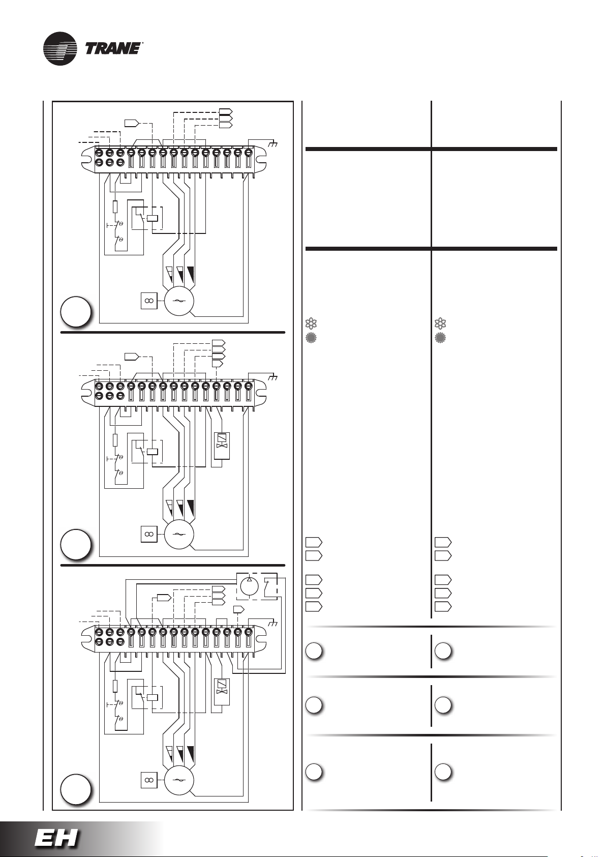
230Vac 50Hz
N
L
PE
PE
GNYE
A
230Vac 50Hz
N
L
PE
PE
GNYE
B
230Vac 50Hz
N
L
PE
V1
EH
BUBU
4 5
N
L
R1
B3
B2
6
BU
BK
Q1
97
8
RD
OG
BU
V2
V3
GNYE
11141210
15
13
MFC
GNYE
COMANDI
E SCHEMI ELETTRICI
LEGENDA LEGEND
BK
MFC = Morsettiera
del FAN COIL
R1 = Resistenza elettrica
M
230V
50Hz
M = Motoventilatore
E = Valvola acqua
(IMPIANTO A 2 TUBI)
= Estate - aria fredda
= Inverno - aria calda
MP = Pompa di evacuazione
consensa
B1 = Contatto NC
EH
V1
V2
V3
BU
BU
A
GNYE
pompa di evacuazione
consensa
4 5
6
8
N
L
BU
BK
R1
Q1
B3
B2
97
11141210
13
15
MFC
GNYE
E
BK
RD
OG
BU
B2 = Termostato
di sicurezza
a riarmo automatico
B3 = Termostato
di sicurezza
a riarmo manuale
Q1 =
Relè di attivazione
resistenza elettrica
GNYE = Giallo/Verde
RD = Rosso = Minima
OG = Arancio = Media
BK = Nero = Massima
BN = Marrone
M
230V
50Hz
BU = Blu
A A
= Ingresso per “E” = Input for “E”
EH EH
= Ingresso per
resistenza elettrica
N
L
V1
EH
BU
BU
V2
V3
A
BK
MP
B1
GNYE
V1 V1
= Velocità minima = Low speed
V2 V2
= Velocità media = Medium speed
V3 V3
= Velocità massima = High speed
ELECTRICAL
CONTROLS AND
WIRING DIAGRAMS
MFC = Fan coil
terminal board
R1 = Electrical heater
M = Fan
E = Water valve
(two tube unit)
= Summer - cold air
= Winter - warm air
MP = Condensate pump
B1 = Normally closed
NC contact
condensate pump
B2 = Self reset
safety thermostat
B3 = Manual reset
safety thermostat
Q1 =
Power-ON relay
GNYE = Yellow/Green
RD = Red = Low
OG = Orange = Medium
BK = Black = High
BN = Brown
BU = Dark blue
Electrical heater
= Input for
electrical heater
C
PELN
GNYE
4 5
6
8 97
BU
BK
R1
Q1
B3
B2
RD
BU
OG
11141210
13
15
MFC
GNYE
E
BK
• Impianto senza valvole
• Termostatazione
A
sul motore
• Impianto 2 tubi
(1 valvola)
B
• Termostatazione
sulla valvola
• Impianto 2 tubi
(1 valvola)
• Termostatazione
M
230V
50Hz
C
sulla valvola
• Pompa di evacuazione
• Without valves installation
• Thermostatic control
A
on the fan
• 2-tube installation
(1 valve)
B
• Thermostatic control
on the valve
• 2-tube installation
(1 valve)
• Thermostatic control
C
on the valve
•
Condensate pump
condensa
UNT-SVX036A-XX31
Page 61
COMMANDES
ET SCHEMAS
ELECTRIQUES
STEUERGERÄTE
UND SCHALTPLÄNE
MANDOS
Y ESQUEMAS
ELÉCTRICOS
BEDIENINGEN
EN ELEKTRISCHE
SCHEMA’S
LÉGENDE LEGENDE LEYENDA LEGENDE
MFC = Bornier
du ventilo-convecteur
R1 = Resistance électrique
M = Motoventilateur
E = Vanne à eau
(installation à 2 tubes)
= Eté - air froid
= Hiver - air chaud
MP = Pompe d’evacuation
des condensats
B1 =
fermé NC pompe d’éva cuation des condensats
B2 = Thermostat
à réarmement
automatique
B3 = Thermostat
à réarmement manuel
Q1 =
résistance électrique
GNYE = Juane/Vert
RD = Rouge = Mini
OG = Orange = Moyenne
BK = Noir = Maxi
BN = Marron
BU = Bleu foncé
EH EH EH EH
V1 V1 V1 V1
V2 V2 V2 V2
V3 V3 V3 V3
Contact normalement
Relais d’activation
A A A A
= Entrée pour “E” = Eingang für “E” = Entrada para “E” = Ingang voor “E”
= Entrée pour
resistance électrique
= Vitesse mini = Mindest Drehzahl = Velocidad minima = Minimale snelheid
= Vitesse moyenne = Mittlere Drehzahl = Velocidad media = Gematigde snelheid
= Vitesse maxi = Hochst Drehzahl = Velocidad maxima = Maximale snelheid
MFC = Klemmenbrett
des FAN COIL
R1 = Elektrischer Widerstand
M = Motorventilator
E = Wasserventil (Anlage
mit zwei Rohren)
= Sommer - kalte Luft
= Winter - warme Luft
MP = Kondensatpumpe
B1 = Ruhekontakt NC
Kondensatpumpe
B2 = Thermostat
mit automatischem
Reset
B3 = Thermostat
mit manuellem Reset
Q1 =
Elektrischer Widerstand
GNYE = Gelb/Grün
RD = Rot = Min
OG = Orange = Med
BK = Schwarz = Max
BN = Braun
BU = Blau
Aktivierungsrelais
= Eingang für
Elektrischer Widerstand
MFC = Borna de conexión
del ventiloconvector
R1 = Resistencia eléctrica
M = Motoventilador
E =
climatización a 2 tubos)
= Verano - aire frio
= Invierno - aire caliente
MP = Bomba de evacuación
de condensados
B1 = Normally closed
NC contact
condensate pump
B2 = Termostato
de rearme automático
B3 = Termostato
de rearme manual
Q1 =
Power-ON relay
GNYE = Amarillo/Verde
RD = Rojo = Mínima
OG = Naranja = Media
BK = Negro = Máxima
BN = Marrón
BU = Azul
Válvula agua (sistema de
Electrical heater
= Entrada para
resistencia eléctrica
MFC = Klemmenbord
ventilatorconvector
R1 = Elektrische weerstand
M = Motorventilator
E = Waterklep
(2-buizige installatie)
= Zomer - koude lucht
= Winter - warme lucht
MP = Condensatwaterpomp
B1 = Normally closed
NC contact
condensate pump
B2 = Thermostaat
met automatische reset
B3 = Thermostaat
met handmatige reset
Q1 =
Power-ON relay
GNYE = Geel/Groen
RD = Rood = Minima
OG = Oranje = Media
BK = Zwart = Massima
BN = Bruin
BU = Donkerblauw
Electrical heater
= Ingang voor
elektrische weerstand
• Installation sans vannes
• Thermostat
A
sur le ventilateur
• Installation à 2 tubes
(1 vanne)
B
• Thermostatation
sur le vanne
• Installation à 2 tubes
(1 vanne)
• Thermostatation
C
sur le vanne
•
Pompe d'evacuation
des condensats
UNT-SVX036A-XX 31A
• Installation ohne Ventile
• Temperaturregelung
A
am Ventilator
• 2-Leiter-System
(1 Ventil)
B
• Temperaturregelung
der Ventile
• 2-Leiter-System
(1 Ventil)
• Temperaturregelung
C
der Ventile
• Kondensatpumpe
• Instalación sin válvulas
• Termostatación
A
sobre el ventilador
• Instalación con 2 tubos
(1 válvula)
B
• Termostatación
sobre la válvula
• Instalación con 2 tubos
(1 válvula)
• Termostatación
C
sobre la válvula
•
Bomba de evacuatión
de condensados
• Installatie Zonder kleppen
• Thermostatische
A
regeling ventilator
• Installatie met 2 leidingen
(1 klep)
B
• Thermostatische
regeling klep
• Installatie met 2 leidingen
(1 klep)
• Thermostatische
C
regeling klep
•
Condenswaterpomp
Page 62
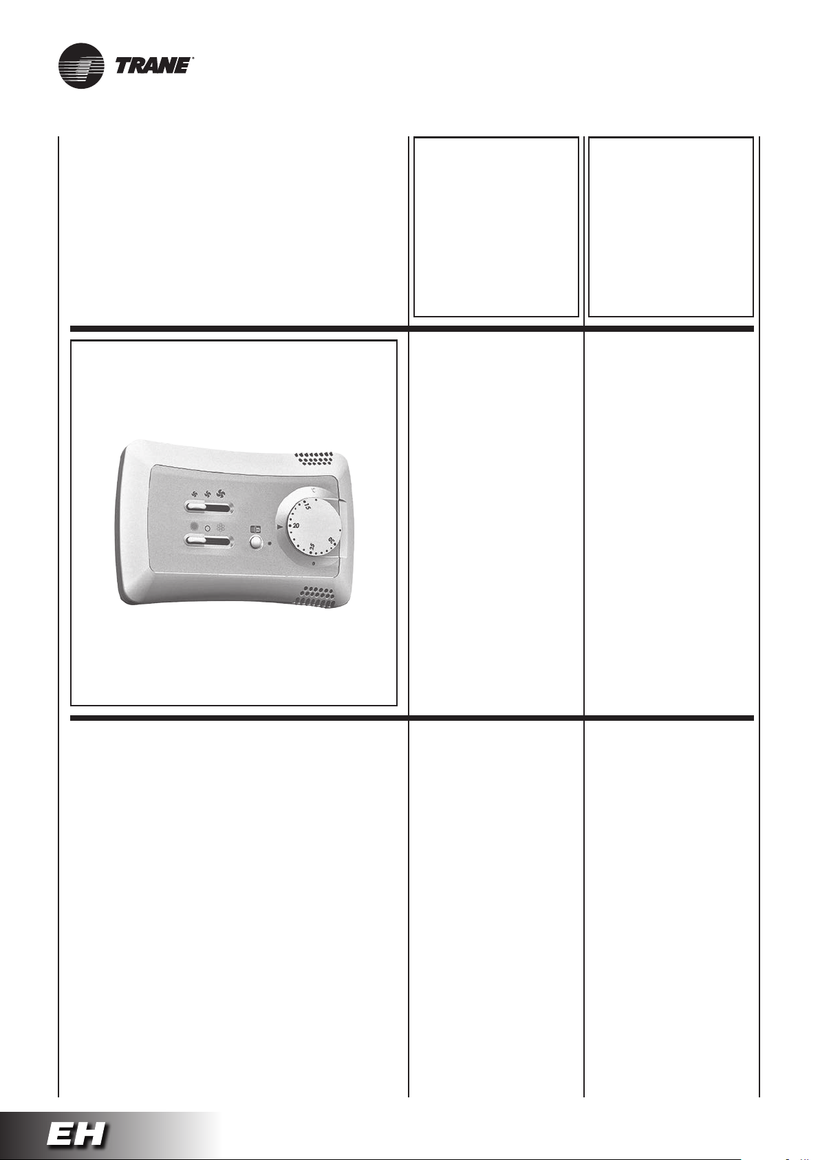
I ventilconvettori
possono essere azionati
con uno dei comandi
montati a parete che,
di seguito, vengono
descritti.
Per l’installazione
e l’utilizzo fare
riferimento al manuale
del comando scelto.
The fan coils
can be operated
using one
of the wall controls
described below.
For the installation
and the use read
carefully the manual
of the chosen control.
“T-REM”
type thermostat
Cod. 353400470-001
Pannello comandi
con termostato elettronico
per impianti a 2 tubi
e resistenza elettrica:
- controllo manuale della velocità
di ventilazione (3 velocità).
- controllo termostatico
del ventilatore o di 1 valvola
e/o resistenza elettrica.
- cambio stagionale
manuale o automatico.
- sonda di minima T3 (accessorio).
“T-REM”
type thermostat
Code 353400470-001
Control panel
with electronic room thermostat
for 2 tube installations
and electric heater:
- manual 3 speed switch.
- electronic room thermostat
for fan control
or for the control of 1 valve
and/or electric heater.
- manual/automatic
Summer/Winter switch.
- optional low temperature
cut-out thermostat T3.
UNT-SVX036A-XX32
Page 63
Les ventilo-convecteurs
peuvent
être actionnés avec
l’une des commandes
murals
décrites ci-après.
Pour l’installation
et l’utilisation
lire attentivement
le manuel de
la commande choisie.
Die Gebläsekonvektoren
können mit
einer der nachstehend
beschriebenen
Wandsteuerungen
bedient werden.
Für die Installation
und den Gebrauch
ist das Handbuch der
ausgewählten Steuerung
sorgfältig zu lesen.
Los fan coils pueden
ser accionados
con uno de los controles
de pared
que se describen
a continuación.
Para la instalación
y la utilización leer
atentamente el manual
del mando elegido.
De ventilatorconvectors
kunnen geactiveerd
worden met één van de
hieronder beschreven
bedieningen die op de
muur gemonteerd zijn.
Voor het installeren
en het gebruik dient
u de handleiding van de
gekozen bediening te
raadplegen.
“T-REM”
type thermostat
Code 353400470-001
Boîtier de commande
avec thermostat électronique
pour installations à 2 tubes
et resistance électrique:
- commutateur 3 vitesses
(manuel).
- controle thermostatique
du ventilateur or de 1 vanne
et/ou résistance électrique.
- commutateur
manuel/automatique été/hiver.
- optionnel thermostat de
limitation basse de soufflage T3.
“T-REM”
type thermostat
Art. Nr. 353400470-001
Bedientafel
mit elektronischem Thermostat
für Anlagen mit 2 Leitern
und elektrischer Widerstand:
- manuelle Umschaltung zwischen
den 3 Ventilatordrehzahlen.
- Temperaturregelung
vom Ventilator
oder von 1 Wasserventil
und/oder elektrischer Widerstand.
- manuelle/automatische
Umschaltung des saisonalen
Zyklus (Sommer - Winter).
- optionaler Mindesttemperatur fühler T3.
“T-REM”
type thermostat
Cód. 353400470-001
Panel de mandos
con termostato electrónico
para instalaciones con 2 tubos
y resistencia eléctrica:
- conmutación manual de las
3 velocidades del ventilador.
- control termostático
del ventilador o de 1 válvula
y/o resistencia eléctrica.
- conmutación manual/automática
verano/invierno.
- sonda de mínima T3 (opcional).
“T-REM”
type thermostat
Code 353400470-001
Bedieningspaneel
met elektronische thermostaat
voor installaties met 2 leidingen
en elektrische weerstand:
- handmatige controle van de
ventilatiesnelheid (3 snelheden).
- thermostatische controle
van de ventilator of van 1 klep
en/eller elektrische weerstand.
- handmatige of automatische
seizoenomschakeling.
- uitschakelthermostaat T3
(accessoire).
UNT-SVX036A-XX 32A
Page 64
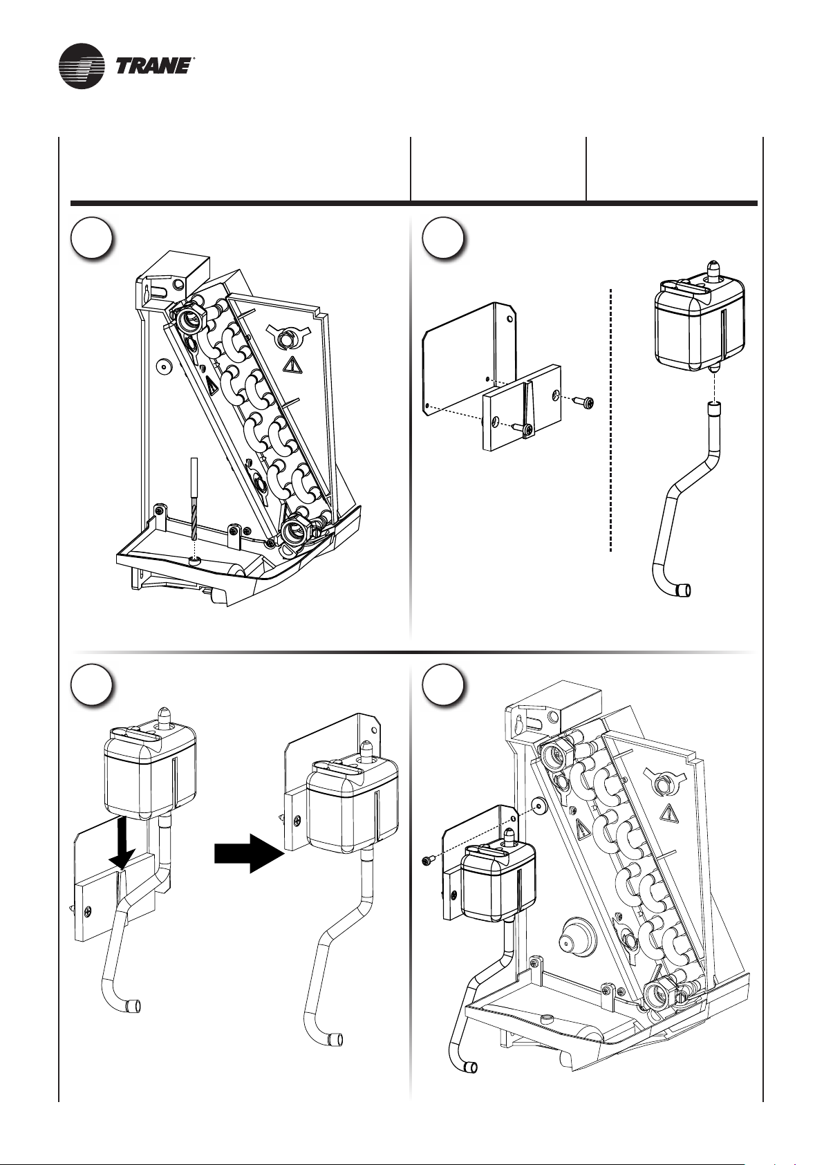
Cod. / Code
Code / Art. Nr.
Cód. / Code
9025309
POMPA
DI EVACUAZIONE
CONDENSA
CONDENSATE
PUMP
1
2
Ø 6
3
4
UNT-SVX036A-XX33
Page 65
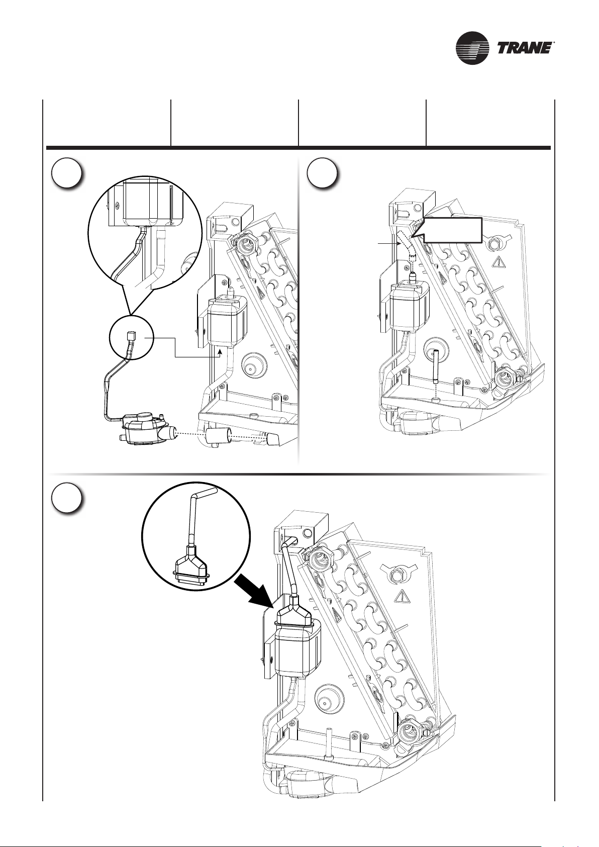
Mandata pompa
Condensate Discharge
Refoulement pompe
Austrittseite der Pumpe
Impulsion de la bomba
Pompblok
POMPE
D’EVACUATION
DES CONDENSATS
KONDENSATPUMPE
BOMBA
DE EVACUATIÓN
DE CONDENSADOS
CONDENSWATERPOMP
5
6
Ø i6
7
UNT-SVX036A-XX 33A
Page 66
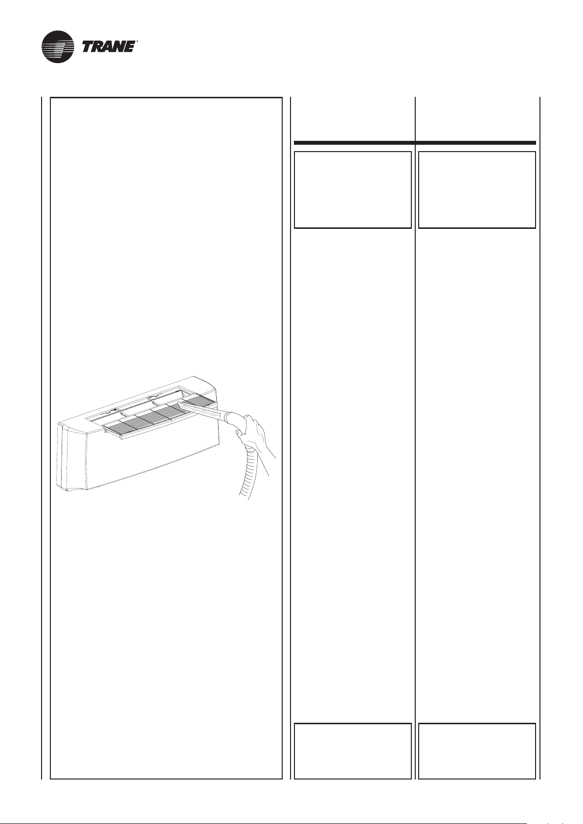
PULIZIA,
MANUTENZIONE,
RICAMBI
CLEANING,
MAINTENANCE
AND SPARE PARTS
ATTENZIONE!
PRIMA DI QUALSIASI
PULIZIA
E MANUTENZIONE,
TOGLIERE
L’ALIMENTAZIONE
ALL’APPARECCHIO.
Solo personale addetto alla manutenzione e precedentemente addestrato, può intervenire sulle apparecchiature.
ELETTROVENTILATORE:
Non richiede alcun tipo di manutenzione.
BATTERIA:
Non richiede alcun tipo di ordinaria manutenzione.
FILTRO:
Con l’ausilio di un utensile, sganciare il profilo portafiltro ed estrarre il filtro dalle guide.
Si pulisce periodicamente usando
un’aspirapolvere oppure percuotendolo leggermente.
Sostituirlo nel caso non si possa
più pulire.
IMPORTANT!
BEFORE CARRYING OUT
CLEANING
OR MAINTENANCE,
MAKE SURE THE POWER
TO THE UNIT
IS TURNED OFF.
Maintenance of the unit must be
carried out by trained maintenance
personnel only.
FAN:
No maintenance required.
HEAT EXCHANGER COIL:
No ordinary maintenance required.
FILTER:
Using a suitable tool, unhook the
filter holder strip and extract the
filter from the guides.
Clean regularly with a vacuum
cleaner or shake lightly.
When it can no longer be cleaned,
replace.
RICAMBI:
Per l’ordinazione delle parti di
ricambio citare sempre il modello
dell’apparecchio e la descrizione
del componente.
ATTENZIONE!
RIMONTARE
SEMPRE IL FILTRO
DOPO
LA SUA PULIZIA.
SPARE PARTS:
To order spare parts, always give
the model of appliance and a
description of the component.
IMPORTANT!
ALWAYS
REPLACE THE FILTER
AFTER CLEANING.
UNT-SVX036A-XX34
Page 67
NETTOYAGE,
ENTRETIEN ET PIECES
DE RECHANGE
REINIGUNG,
WARTUNG UND
ERSATZTEILE
LIMPIEZA,
MANTENIMIENTO
Y REPUESTOS
SCHOONMAAK,
ONDERHOUD,
WISSELSTUKKEN
ATTENTION!
AVAN T
TOUTE OPERATION
DE NETTOYAGE ET
D’ENTRETIEN,
COUPER L’ALIMENTATION
DE L’APPAREIL.
Seul le personnel chargé de l’entretien
et ayant été formé dans ce but peut
intervenir sur les appareils.
VENTILATEUR:
Ne nécessite aucun type d’entretien.
BATTERIE:
Ne nécessite aucun type d’entretien.
ordinaire.
FILTRE:
Au moyen d’un outil, décrocher le
profilé porte-filtre et retirer le filtre
de ses guides.
Doit être nettoyé périodiquement
à l’aide d’un aspirateur ou en le
frappant légèrement.
Le remplacer lorsqu’il n’est plus
possible de le nettoyer.
WARTUNGSARBEITEN MUSS
Nur das mit der Wartung vertraute
und vorher entsprechend geschulte
Personal darf Eingriffe an den
Geräten vornehmen
ELEKTROVENTILATOR:
Dieser bedarf keinerlei Wartung.
REGISTER:
Bedarf keiner Wartung wenn der
Filter regelmäßig gereinigt wird.
FILTER:
Mit Hilfe eines Werkzeuges das
Filter-Halteprofil aushängen und den
Filter aus den Führungen nehmen.
Der Filter wird regelmäßig mit
einem Staubsauger oder durch
vorsichtiges Ausklopfen gesäubert.
Wenn er sich nicht mehr reinigen
lässt, muss er ersetzt werden.
ACHTUNG!
VOR BEGINN
VON REINIGUNGS- UND
MUSS DIE STROMZUFUHR
ZUM GERÄT
UNTERBROCHEN WERDEN.
ATENCIÓN!
ANTES DE EFECTUAR
CUALQUIER OPERACIÓN
DE LIMPIEZA
Y MANTENIMIENTO
CORTAR LA ALIMENTACIÓN
PARA EL APARATO.
Sólo personal encargado del mantenimiento y previamente capacitado
puede efectuar operaciones sobre
los aparatos.
VENTILADOR:
No requiere ninguna clase de
mantenimiento.
BATERÍA:
No requiere ninguna clase de
mantenimiento ordinario.
FILTRO:
Con el auxilio de una herramienta,
desenganchar el perfil porta-filtro
y retirar el filtro de las guías.
Se limpia periódicamente usando
una aspiradora o golpeándolo ligeramente.
Si no es posible limpiarlo sustituirlo.
OPGELET!
VOOR ELKE
SCHOONMAAK- EN
ONDERHOUDSBEURT,
DE STEKKER VAN HET
APPARAAT UIT HET
STOPCONTACT TREKKEN.
Wend u uitsluitend tot opgeleid
onderhoudspersoneel voor het
onderhoud van het apparaat.
ELEKTROVENTILATOR:
Vergt geen enkel type onderhoud.
BATTERIj:
Vergt geen enkel type gewoon
onderhoud.
FILTER:
Met behulp van gereedschap, haakt
u de filterhouder los en haalt u hem
uit zijn zitting.
Maak de filter regelmatig schoon
met een stofzuiger of door er zacht
op te kloppen.
Vervang de filter indien hij niet kan
worden schoongemaakt.
PIECES DE RECHANGE:
Pour la commande des pièces
de rechange, indiquer toujours le
modèle de l’appareil et la description
du composant.
ATTENTION!
APRES L’AVOIR NETTOYE,
NE JAMAIS OUBLIER
DE REMONTER
LE FILTRE.
ERSATZTEILE:
Bei Ersatzteilbestellungen immer das
Gerätemodell und die Bezeichnung
des Teils angeben.
WICHTIG!
Die Betriebsanleitung ist Teil der
Lieferung und Bestandteil des Gerätes.
Sie muss vor der Montage aufmerksam
gelesen und dem Bauherrn nach
Fertigstellung übergeben werden.
Die Gewährleistung kann nur nach
Vorlage der Betriebs- und Wartungsanleitung und entsprechend großer
Revisionsöffnung gewährt werden.
Ebenso entfällt der Gewährleistungsanspruch wenn die notwendige
jährliche Wartung der Geräte (durch
die Sabiatech od. durch einen
nachweislich befugten Fachbetrieb)
nicht durchgeführt wurde.
ACHTUNG!
NICHT VERGESSEN,
DEN FILTER NACH
DER REINIGUNG
WIEDER EINZUBAUEN.
REPUESTOS:
Para pedir piezas de repuesto indicar siempre el modelo del aparato
y la descripción del componente.
ATENCIÓN!
DESPUÉS DE LIMPIARLO
VOLVER A MONTAR
SIEMPRE EL FILTRO
EN SU SITO.
WISSELSTUKKEN:
Bij de bestelling van de wisselstukken,
vermeld u steeds het model van het
apparaat en beschrijft u het onderdeel.
OPGELET!
HERPLAATS DE FILTER
STEEDS NA EEN
SCHOONMAAKBEURT.
UNT-SVX036A-XX 34A
Page 68
RICERCA GUASTI
TROUBLESHOOTING
GUASTO
1 - Il motore non gira
o gira in modo non corretto.
RIMEDIO
- Controllare che
l’alimentazione sia inserita.
- Verificare il collegamento
corretto dei fili, osservando
gli schemi elettrici.
- Verificare la posizione
dell’interruttore generale,
del commutatore stagionale
e del termostato.
GUASTO
2 - L’apparecchio
non scalda/raffredda più
come in precedenza.
RIMEDIO
- Controllare che il filtro
sia sufficientemente pulito.
- Verificare sfiatando la batteria
che non sia entrata aria
nel circuito idraulico.
PROBLEM
1 - The motor does not rotate
or rotates incorrectly.
REMEDY
- Make sure
the power to the unit is on.
- Make sure the wires
are correctly connected,
referring to the wiring diagram.
- Control if the main switch,
the seasonal commutator
and the thermostat
are in the right position.
PROBLEM
2 - The unit does not heat/cool
as before.
REMEDY
- Make sure the filter is clean.
-
Make sure the hydraulic circuit
is free from air by venting
the heat exchanger.
GUASTO
3 - L’apparecchio perde acqua.
RIMEDIO
- Controllare che l’inclinazione
sia in direzione
dello scarico condensa.
- Controllare
che lo scarico condensa
non sia ostruito.
PROBLEM
3 - The appliance leaks water.
REMEDY
- Make sure
it is sloping in the direction
of the condensate drain.
- Make sure
the condensate drain
is not clogged.
UNT-SVX036A-XX35
Page 69

DEPANNAGE FEHLERSUCHE
INVESTIGACIÓN
DE AVERÍAS
OPSPOREN
DEFECTEN
DEFAUT
1 - Le moteur ne tourne pas ou
tourne de manière incorrecte.
ACTION CORRECTIVE
- Contrôler que
l’alimentation est branchée.
- Vérifier le bon raccordement
des conducteurs à l’aide
des schémas électriques.
- L’interrupteur général
et le commutateur saisonnier
soient dans
la position correcte.
DEFAUT
2 - L’appareil
ne chauffe ou ne refroidit plus
comme avant.
ACTION CORRECTIVE
- Contrôler que le filtre
est suffisamment propre.
- Vérifier, en purgeant la
batterie, que de l’air n’est pas
entré dans le circuit hydraulique.
STÖRUNG
1 - Der Motor dreht nicht
oder dreht nicht korrekt.
ABHILFE
-
Kontrollieren, ob die Spannungs-
versorgung zugeschaltet ist.
-
Auf Grundlage der Schaltpläne
den korrekten Anschluss
der Drähte prüfen.
- Die Position des Haupt schalters, des Umschalters
der Betriebsart und
des Thermostats kontrollieren.
STÖRUNG
2 - Das Gerät heizt/kühlt nicht
mehr wie zuvor.
ABHILFE
- Kontrollieren, ob der Filter
sauber genug ist.
- Durch Entlüften des Registers
kontrollieren, ob Luft in den
Wasserkreis eingedrungen ist.
AVERÍA
1 - El motor no gira
o gira de modo incorrecto.
SOLUCIÓN
- Verificar que esté conectado
a la toma de corriente.
- Verificar la correcta conexión
de los hilos, observando
los esquemas eléctricos.
- Verificar la posición
del interruptor general,
del conmutador estacional
y del termostato.
AVERÍA
2 - El aparato
ya no calienta/enfría
como con anterioridad.
SOLUCIÓN
- Verificar que el filtro
esté bien limpio.
- Verificar purgando la batería
que no haya entrado aire
en el circuito hidráulico.
DEFECT
1 - De motor draait niet
of op niet correcte wijze.
OPLOSSING
- Controleer of de stekker
in het stopcontact zit.
- Controleer de correcte
aansluiting van de draden,
conform de schakelschema’s.
- Controleer de positie
van de hoofdschakelaar,
de seizoensschakelaar
en de thermostaat.
DEFECT
2 - Het apparaat
verwarmt/koelt niet
meer af zoals voordien.
OPLOSSING
- Controleer of de filter
voldoende schoon is.
- Tap de batterij af en ga
de aanwezigheid na van lucht
in het hydraulisch circuit.
DEFAUT
3 - L’appareil perd de l’eau.
ACTION CORRECTIVE
- Contrôler que l’évacuation
des condensats est inclinée
dans la bonne direction.
- Contrôler que
l’évacuation des condensats
n’est pas bouchée.
STÖRUNG
3 - Das Gerät verliert Wasser.
ABHILFE
- Kontrollieren, ob
die Schräge in Richtung des
Kondensatabflusses verläuft.
- Kontrollieren, ob
der Kondensatabfluss
frei ist.
AVERÍA
3 - El aparato pierde agua.
SOLUCIÓN
- Controlar que esté inclinado
en dirección a la evacuación
del agua de condensación.
- Controlar que la evacuación
del agua de condensación
no esté obstruida.
DEFECT
3 - Er lekt water uit het apparaat.
OPLOSSING
- Controleer of de helling in de
richting van de afvoerbuis voor
het condensatievocht loopt.
- Controleer of de afvoerbuis
voor het condensatievocht
niet verstopt is.
UNT-SVX036A-XX 35A
Page 70
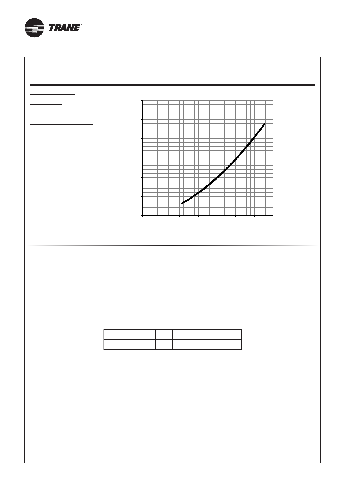
20
30
40
50
60
10
20
0 100 200 300 400 500 600 700
PERDITE DI CARICO LATO ACQUA - PRESSURE DROP TABLE
PERTES DE CHARGE CÔTE EAU - DRUCKVERLUSTE WASSER
PÉRDIDAS DE CARGA LADO AGUA - WATERLEKKEN
Batteria a 2 ranghi
2 row battery
Batterie à 2 rangs
Register mit 2 Rohrreihen
Batería de 2 filas
Batterij met 2 rijen
per temperature diverse, moltiplicare la perdita di carico per il coefficiente K riportato in tabella.
Pour une température différente, multiplier la perte de charge par le coefficient K de le table suivante.
Der Druckverlust bezieht sich auf eine durchschnittliche Temperatur des Wassers von 10°C;
für abweichende Temperaturen den Druckverlust mit dem Koeffizienten K der Tabelle multiplizieren.
para temperaturas distintas multiplicar la pérdida de carga por el coeficiente K que figura en la tabla.
bij verschillende temperaturen vermenigvuldigt u het energieverlies met de coëfficiënt K die u in de tabel vindt.
Dp - kPa
0
Portata acqua (l/h) - Water flow (l/h) - Débit d’eau (l/h)
Wasserdurchflussmenge (l/h) - Caudal de agua (l/h) - Waterdebiet (l/h)
La perdita di carico si riferisce ad una temperatura media dell’acqua di 10°C;
The table indicates the pressure drop for a mean water temperature of 10°C.
For different water temperatures multiply by the correction factors K.
La perte de charge se référe à une température moyenne d’eau de 10°C.
La pérdida de carga se refiere a una temperatura media del agua de 10°C;
Het energieverlies verwijst naar een gemiddelde watertemperatuur van 10°C;
°c
K
36
20 30 40 50 60 70 80
0,94 0,90 0,86 0,82 0,78 0,74 0,70
UNT-SVX036A-XX
Page 71
NOTES
UNT-SVX036A-XX
Page 72
Trane optimizes the performance of homes and buildings around the world. A business of Ingersoll Rand,
the leader in creating and sustaining safe, comfortable and energy efficient environments, Trane offers
a broad portfolio of advanced controls and HVAC systems, comprehensive building services, and parts.
For more information, visit www.Trane.com.
Trane has a policy of continuous product and product data improvement and reserves the right to change design and specifications
without notice.
© 2016 Trane All rights reserved
UNT-SVX036A-XX September 01, 2016 Supersedes:
Digitally printed on environmentally friendly paper;
produced using fewer trees and chemicals and less energy.
 Loading...