

Page 1

September 2014
UNT-SVX26B-XX
FVAE / FCAE / FKAE
Technical guide
Fan coil units
Ventilo-convecteurs
Gebläse-Konvektoren
Ventiladores convectores
Ventilconvettori
Ventilators-convectors
Page 2

UNT-SVX26B-XX UNT-SVX26B-XX
INDICE
Scopo
Identificazione macchina
Trasporto
Pesi
e dimensioni unità imballata
Note generali alla consegna
Avvertenze generali
Regole
fondamentali di sicurezza
Prescrizioni di sicurezza
Limiti di impiego
Smaltimento
Caratteristiche tecniche
Installazione meccanica
Collegamento idraulico
Collegamenti elettrici
Scheda ECM
Comandi
e schemi elettrici
Legenda
Pulizia,
manutenzione, ricambi
Ricerca guasti
Perdite di carico lato acqua
2
3
4
4
5
5
6
7
9
9
10
12
13
17
19
21
21
36
37
38
SCOPO
PRIMA DI INSTALLARE
L’APPARECCHIO
LEGGERE ATTENTAMENTE
QUESTO MANUALE
I Ventilconvettori sono stati ideati, progettati e costruiti per riscaldare/raffrescare qualsiasi ambiente civile, industriale, commerciale e sportivo.
L’apparecchio
non può essere impiegato:
• per il trattamento dell’aria
all’aperto
• per l’installazione in ambienti
umidi
• per l’installazione
in atmosfere esplosive
• per l’installazione
in atmosfere corrosive
Verificare che l’ambiente in cui è
installato l’apparecchio non contenga sostanze che generino un
processo di corrosione delle alette
in alluminio.
Gli apparecchi sono alimentati con acqua calda/fredda a seconda che si voglia riscaldare o raffrescare l’ambiente.
Questo apparecchio è destinato ad essere utilizzato da utenti esperti o formati
nei negozi, nell’industria leggera e nelle
aziende agricole, o per uso commerciale da parte di personale non esperto.
L’apparecchio non è destinato ad essere usato da persone (bambini compresi) le cui capacità fisiche, sensoriali o mentali siano ridotte, oppure con
mancanza di esperienza o di conoscenza, a meno che esse abbiano potuto
beneficiare, attraverso l’intermediazione di una persona responsabile della loro sicurezza, di una sorveglianza
o di istruzioni riguardanti l’uso dell’apparecchio.
I bambini devono essere sorvegliati
per sincerarsi che non giochino con
l’apparecchio.
ISTRUZIONI ORIGINALI
INDEX
Application
Identifying the appliance
Transport
Weights
and dimension packed unit
General notes on delivery
General warnings
Fundamental safety rules
Safety rules
Operating limits
Waste disposal
Technical characteristics
Mechanical installation
Hydraulic connections
Electrical connections
ECM electronic board
Electrical controls
and wiring diagrams
Legend
Cleaning,
maintenance and spare parts
Troubleshooting
Pressure drop table
2
3
4
4
5
5
6
7
9
9
10
12
13
17
19
21
21
36
37
38
APPLICATION
CAREFULLY
READ THIS MANUAL
BEFORE INSTALLING
THE APPLIANCE
The fan coils are conceived, designed
and produced to heat/cool all civil,
industrial, commercial or sports
premises.
The appliance
may not be used:
• for outdoor air treatment
• for installation in moist rooms
• for installation
in explosive atmospheres
• for installation
in corrosive atmospheres
Make sure that the environment
where the appliance is installed
does not contain substances
that cause the corrosion of the
aluminium fins.
The appliances are supplied with hot/
cold water depending on whether the
environment is being heated/cooled.
This unit is intended to be used by
expert or trained users in shops, in
light industry and on farms, or for
commercial use by lay persons.
This unit is not intended for use
by persons (including children) with
reduced physical, sensory or mental
capabilities, or lack of experience and
knowledge, unless they have been given
supervision or instruction concerning
use of the appliance by a person
responsible for their safety.
Children should be supervised to
ensure that they do not play with the
appliance.
2 2A
TABLE DES MATIÈRES INHALT ÍNDICE INHOUD
BUT ZWECKBESTIMMUNG OBJETIVO DOEL
But
Identification des machines
Transport
Poids et
dimensions de l’unité emballée
Remarques générales
pour la livraison
Généralités
Règles fondamentales
de sécurité
Consignes de sécurité
Limites d’emploi
Élimination
Caractéristiques techniques
Installation mécanique
Raccordement hydraulique
Branchements électriques
Bornier ECM
Commandes
et schémas électriques
Légende
Nettoyage, entretien
et pièces de rechange
Dépannage
Pertes de charge côté eau
2
3
4
4
5
5
6
7
9
9
10
12
13
17
19
21
21
36
37
38
Zweckbestimmung
Kennzeichnung des Geräts
Transport
Gewicht und
dimensionen verpacktes gerät
Allgemeine Hinweise
zur Lieferung
Allgemeine Hinweise
Grundsätzliche
Sicherheitsvorschriften
Sicherheitsvorschriften
Einsatzgrenzen
Entsorgung
Technische Eigenschaften
Mechanische Installation
Wasseranschluss
Elektroanschlüsse
Elektronikplatine ECM
Steuerungen und Schaltpläne
Legende
Reinigung,
Wartung, Ersatzteile
Fehlersuche
Druckverluste Wasser
2
3
4
4
5
5
6
7
9
9
10
12
13
17
19
21
21
36
37
38
Objetivo
Identificación de la máquina
Transporte
Peso
y dimensión unidad embalado
Notas generales
para la entrega
Advertencias generales
Normas fundamentales
de seguridad
Prescripciones de seguridad
Límites de uso
Eliminación
Características técnicas
Instalación mecánica
Conexión hidráulica
Conexiones eléctricas
Tarjeta ECM
Mandos
y esquemas eléctricos
Leyenda
Limpieza,
mantenimiento, recambio
Investigación de averías
Pérdidas de carga lado agua
2
3
4
4
5
5
6
7
9
9
10
12
13
17
19
21
21
36
37
38
Doel
Identificatie apparaat
Transport
Gewicht en
afmetingen verpakte eenheid
Algemene
opmerkingen bij de levering
Algemene voorschriften
Belangrijke
veiligheidsvoorschriften
Veiligheidsvoorschriften
Gebruikslimieten
Afdanking
Technische karakteristieken
Mechanische installatie
Hydraulische aansluiting
Elektrische aansluitingen
Schakeling ECM
Bedieningen
en schakelschema’s
Legende
Schoonmaak,
onderhoud, wisselstukken
Opsporen defecten
Waterlekken
2
3
4
4
5
5
6
7
9
9
10
12
13
17
19
21
21
36
37
38
AVANT D’INSTALLER
L’APPAREIL
LIRE ATTENTIVEMENT
CE MANUEL
Les ventilo-convecteurs ont été conçus
et construits pour chauffer/rafraîchir
n’importe quelle ambiance civile,
industrielle, commerciale et sportive.
L’appareil ne peut pas:
• pour le traitement de l’air
en plein air
• être installé dans des locaux
humides
• être installé dans
des atmosphères explosives
• être installé dans
des atmosphères corrosives
Vérifier que la pièce dans laquelle
l’appareil est installé ne contient
pas de substances pouvant engendrer la corrosion des ailettes
en aluminium.
Les appareils sont alimentés avec de
l’eau chaude/froide selon qu’on veut
chauffer ou rafraîchir la pièce.
Cet appareil est destiné à être utilisé par
des utilisateurs expérimentés ou des
formats dans les magasins, chez des
artisans et dans des fermes, ou à des
fins commerciales par des non-experts.
L’appareil n’est pas prévu pour être
utilisé par des personnes (y compris les
enfants) dont les capacités physiques,
sensorielles ou mentales sont réduites,
ou dénuées d’expérience ou de
connaissance, sauf si elles ont pu
bénéficier, par l’intermédiaire d’une
personne responsable de leur sécurité,
d’une surveillance ou d’instructions
préalables concernant l’utilisation de
l’appareil.
Il convient de surveiller les enfants
pour s’assurer qu’ils ne jouent pas
avec l’appareil.
BEVOR DAS GERÄT
INSTALLIERT WIRD, SOLLTE
DIESES HANDBUCH SORG-
FÄLTIG GELESEN WERDEN
Die Gebläsekonvektoren wurden konzipiert,
entworfen und gebaut, um zivil, industriell,
gewerblich und zu sportlichen Zwecken
genutzte Räume zu heizen bzw. zu kühlen.
Die Geräte darf nicht
eingesetzt werden für:
• die Aufbereitung der Luft
im Freien
• die Installation in feuchten
Räumen
• die Installation
in explosiver Atmosphäre
• die Installation
in korrosiver Atmosphäre
Überprüfen, dass der Raum, in dem
das Gerät installiert wird, keine Stoffe
enthält, die einen Korrosionsprozess
der Aluminiumrippen bewirken.
Je nachdem, ob der Raum beheizt oder
gekühlt werden soll, werden die Geräte
mit warmem, bzw. kalten Wasser gespeist.
Dieses Gerät ist dafür bestimmt, durch
erfahrene Benutzer oder Formate in Geschäften
verwendet werden, in der Leichtindustrie
und auf Bauernhöfen, oder für die kommerzielle
Nutzung von Nicht-Experten.
Dieses Gerät ist nicht dafür bestimmt,
durch Personen (einschließlich Kinder),
mit eingeschränkten physischen,
sensorischen oder geistigen Fähigkeiten oder mangels Erfahrung und/
oder mangels Wissen benutzt zu werden,
es sei denn sie werden durch eine für
ihre Sicherheit zuständige Person
beaufsichtigt oder erhielten von ihr
Anweisungen, wie das Gerät zu
benutzen ist.
Kinder sollten beaufsichtigt werden,
um sicherzustellen, dass sie nicht mit
dem Gerät spielen.
ANTES DE INSTALAR
EL APARATO
LEA ATENTAMENTE
ESTE MANUAL
Los fan coils han sido diseñados, proyectados y construidos para calentar/
refrescar toda clase de ambiente domestico, industrial, comercial y deportivo.
Los aparatos
no se pueden usar para:
• el tratamiento del aire
al aire libre
• su instalación
en locales húmedos
• su instalación
en atmósferas explosivas
• su instalación
en atmósferas corrosivas
Compruebe que la estancia en la
que se está instalado el aparato no
contenga sustancias que generen
un proceso de corrosión de las
aletas de aluminio.
Los aparatos se alimentan con agua
caliente/fría según si se desea calentar o refrescar el local.
Este aparato está diseñado para ser
utilizado por los usuarios o formatos
experimentados en las tiendas, en la
industria ligera y en granjas, o para el
uso comercial por los no expertos.
Este aparato no debe ser utilizado
por personas (incluidos niños) cuyas
capacidades físicas, sensoriales o
mentales estén disminuidas o que
carezcan de experiencia y conocimientos, al no ser que ellas hayan
podido beneficiar, a través de la intermediación de una persona responsable de su seguridad, de una vigilancia o de instrucciones relativas al
uso del aparato.
Los niños han de vigilarse para asegurarse de que no jueguen con el
aparato.
VÓÓR DE INSTALLATIE
VAN HET APPARAAT
NEEMT U AANDACHTIG
DEZE HANDLEIDING DOOR
De ventilatorconvectors werden
ontworpen om privé-ruimtes, industriële,
commerciële en sportieve ruimtes te
verwarmen/af te koelen.
De ventilators-convectors
mag niet worden gebruikt:
• voor de zuivering
van de buitenlucht
• voor installatie
in vochtige ruimten
• voorinstallatie in ruimten waar
ontploffingsgevaar heerst
• voor installatie
in corrosieve omgevingen
Controleer of de omgeving waarin
het apparaat geïnstalleerd is geen
stoffen bevat die een roestproces
van de aluminium ribben op gang
brengen.
De apparaten worden gevoed met
warm/koud water, naargelang men de
ruimte wenst af te koelen of te verwarmen.
Dit apparaat is bedoeld om te worden
gebruikt door ervaren gebruikers of
formaten in winkels, in de lichte industrie
en op boerderijen, of voor commercieel
gebruik door niet-deskundigen.
Het apparaat is niet bestemd voor
gebruik door personen (kinderen
inbegrepen) met beperkte fysieke,
sensoriële of mentale capaciteiten of
met onvoldoende ervaring of kennis,
tenzij ze gebruik hebben kunnen maken,
dankzij het toedoen van iemand die
verantwoordelijk is voor hun veiligheid,
van toezicht of aanwijzingen over het
gebruik van het apparaat.
Kinderen dienen onder toezicht te
staan om zich ervan te verzekeren
dat zij niet met het apparaat spelen.
Page 3

UNT-SVX26B-XX UNT-SVX26B-XX3 3A
I componenti principali sono:
MOBILETTO DI COPERTURA di tipo misto in lamiera d’acciaio zincata
a caldo preverniciata e spalle in materiale sintetico antiurto. È facilmente
smontabile per una completa accessibilità dell’apparecchio.
La griglia di mandata dell’aria, facente parte del mobiletto, è di tipo reversibile ad alette fisse e posizionato sulla parte superiore.
GRUPPO VENTILATORE
Costituito da ventilatori centrifughi a
doppia aspirazione, particolarmente
silenziosi con giranti in alluminio bilanciate staticamente e dinamicamente,
direttamente calettate sull’albero motore.
MOTORE ELETTRICO
Motore elettronico brushless sincrono
a magneti permanenti, del tipo trifase,
controllato con corrente ricostruita secondo un’onda sinusoidale BLAC. La
scheda elettronica ad inverter per il
controllo del funzionamento motore è
alimentata a 230 Volt in monofase e,
con un sistema di switching, provvede
alla generazione di una alimentazione
di tipo trifase modulata in frequenza e
forma d’onda. Il tipo di alimentazione
elettrica richiesta per la macchina è quindi monofase con tensione 230 - 240 V
e frequenza 50 - 60 Hz.
BATTERIA
DI SCAMBIO TERMICO
È costruita con tubi di rame ed alette
in alluminio fissate ai tubi con procedimento di mandrinatura meccanica.
Nella versione a 3-4 ranghi la batteria
è dotata di 2 attacchi Ø 1/2” gas femmina. I collettori delle batterie sono
corredati di sfoghi d’aria e di scarichi
d’acqua Ø 1/8” gas. I Ventilconvettori
possono essere corredati di batteria
addizionale (solo per riscaldamento),
con attacchi femmina Ø 1/2” gas (versione 3 o 4 ranghi più 1 - versione 3
ranghi più 2; per impianti a 4 tubi).
L
A POSIZIONE
DI
SERIE DEGLI ATTACCHI
È
A SINISTRA,
GUARDANDO L’APPARECCHIO.
Su richiesta, o comunque con facile
operazione eseguibile in cantiere, la
posizione degli attacchi può essere
spostata a destra.
FILTRO
di materiale sintetico rigenerabile.
BACINELLA
RACCOLTA CONDENSA in mate-
riale plastico, realizzata a forma di L
e fissata alla struttura interna.
A bordo di ogni singola macchina è
applicata l’etichetta di identificazione
riportante i dati del costruttore ed il
tipo di macchina.
L’etichetta è posizionata sul lato dei
comandi elettrici, all’interno dell’apparecchio.
The main components are:
CASING
In prepainted hot galvanised sheet steel
with synthetic impact resistant side
panels. Easy to remove for complete
access to the unit.
The air discharge grid incorporated
in the top of the casing is reversible
with fixed louvres.
FAN ASSEMBLY
Ultra-silent double intake centrifugal
fans with statically and dynamically
balanced aluminium impellers keyed
directly onto the motor shaft.
ELECTRIC MOTOR
Three phase permanent magnet DC
brushless electronic motor that is
controlled with current reconstructed
according to a BLAC sinusoidal wave.
The inverter board that controls the
motor operation is powered by 230 Volt,
single-phase and, with a switching
system, it generates a three-phase
frequency modulated, wave form power
supply. The electric power supply
required for the machine is therefore
single-phase with voltage of 230 - 240 V
and frequency of 50 - 60 Hz.
HEAT
EXCHANGE COIL
Made with aluminium finned copper
tubes. The 3-4 row exchanger has two
1/2” female gas connections. Coil
headers with air vents and water drain
outlets (1/8” dia. gas). The units can be
fitted with a supplementary exchanger
(for heating only) with 1/2” dia. gas
female connections (3 or 4 row plus
1 version - 3 row plus 2 version; for
4-tube installations).
A
S STANDARD,
THE CONNECTIONS
ARE
ON THE LEFT HAND SIDE
FACING
THE UNIT.
The units can be supplied if specified
with the connections on the right hand
side. Alternatively the connections can
easily be moved from one side to the
other on site.
Regenerable
synthetic FILTER.
CONDENSATE
DRAIN PAN, plastic, L-shaped, fixed
to internal structure.
Each unit is supplied with an identification
plate giving details of the manufacturer
and the type of appliance.
The label is located inside the appliance
on the electric controls side.
Les composants principaux sont:
CARROSSERIE de type mixte en tôle
d’acier zinguée à chaud prépeinte et
panneaux latéraux en matière synthétique
antichoc. Elle est facilement démontable,
ce qui offre une accessibilité totale à
l’appareil.
La grille de refoulement de l’air, qui
fait partie de la carrosserie, est du
type réversible à ailettes fixes et se
trouve sur la partie supérieure.
GROUPE VENTILATEUR
Constitué par des ventilateurs centrifuges à double aspiration, particulièrement silencieux, avec des turbines
en aluminium équilibrées statiquement
et dynamiquement, directement fixées
sur l’arbre moteur.
MOTEUR ÉLECTRIQUE
Moteur électronique brushless synchrone
à aimants permanents de type triphasé,
contrôlé avec courant reconstruit selon
une onde sinusoïdale BLAC. La carte
électronique à inverter pour le contrôle
du fonctionnement moteur est alimentée
à 230 Volt en monophasé et, avec un
système de switching, pourvoit à la
génération d’une alimentation de type
triphasée modulée en fréquence et forme
d’onde. Le type d’alimentation électrique
requis pour la machine est donc monophasé avec tension 230 - 240 V et
fréquence 50 - 60 Hz.
BATTERIE
D’ÉCHANGE THERMIQUE
Construite avec des tubes en cuivre et
des ailettes en aluminium fixées aux
tubes par dudgeonnage mécanique.
Dans la version à 3-4 rangs, la batterie
est équipée de deux raccords Ø 1/2” gaz
femelle. Les collecteurs des batteries
sont dotés de purgeurs d’air et de sorties
d’eau Ø 1/8” gaz. Les ventilo-convecteurs
peuvent être équipés d’une batterie
supplémentaire (seulement pour le
chauffage), avec des raccords femelle
Ø 1/2” gaz (version 3 ou 4 rangs plus 1
- version 3 rangs plus 2; pour installations
à 4 tuyauteries).
LA POSITION
STANDARD
DES RACCORDS
EST
À GAUCHE,
QUAND ON REGARDE L’APPAREIL.
Sur demande ou par une simple
opération pouvant être pratiquée en
chantier, la position des raccords
peut-être déplacée à droite.
FILTRE
en matière synthétique régénérable.
BAC DE RECUPERATION
DES CONDENSATS, en matière
plastique, réalisé en forme de “L“ et
fixé à la structure interne.
Une étiquette d’identification est
appliquée sur chaque machine; elle
indique les données du constructeur
et le type de machine.
Cette étiquette se trouve sur le côté des
commandes électriques, à l’intérieur
de l’appareil.
Das Gerät setzt sich hauptsächlich aus
folgenden Bauteilen zusammen:
GEHÄUSE aus feuerverzinktem und
vorlackiertem Stahlblech mit Seitenteilen aus stoßfestem Kunststoff. Das
Gehäuse kann vollständig abgenommen
werden, um ungehindert Zugang zum
Gerät zu haben.
Das Ausblasgitter mit festen Luftleitlamellen, das Teil des Gehäuses
ist, ist umsteckbar und befindet sich
auf der Geräteoberseite.
GEBLÄSE
Bestehend aus besonders geräuscharmen, doppelseitig saugenden Radialventilatoren mit statisch und dynamisch
ausgewuchteten Laufrädern aus
Aluminium, direkt auf der Antriebswelle
sitzend.
ELEKTROMOTOR
Einem dreiphasigen elektronischen
Brushless-Gleichstrommotor mit
Permanentmagneten Typ BLAC gekoppelt,
der mit Sinusstrom gesteuert wird. Der
elektronische Frequenzumrichter für
die Motorsteuerung wird einphasig mit
230 Volt gespeist. Er generiert auf Basis
eines Switching-Systems frequenzmodulierten und wellenförmigen Dreiphasenstrom. Aus diesem Grund benötigt
das Gerät eine einphasige Stromversorgung
mit einer Spannung von 230 – 240 V und
einer Frequenz von 50 – 60 Hz.
WÄRMETAUSCHERBATTERIE
Bestehend aus Kupferrohren mit
maschinell aufgezogenen Aluminiumlamellen. Die 3- und 4- reihigen Wärmetauscher sind mit zwei Anschlüssen mit
Innengewinde ø 1/2” Gas versehen.
Die Sammler der Wärmetauscher
sind mit Entlüftungsöffnungen und
Wasserablass-Anschlüssen ø 1/8” Gas
versehen. Die Geräte können mit einem
Zusatz-Wärmetauscher (nur für Heizung)
mit Innengewinde-Anschlüssen ø 1/2”
Gas ausgestattet werden (Ausführung
3 oder 4 plus 1 Reihe - Ausführung 3
plus 2 Reihen; für 4-Leiter-System).
S
ERIENMÄßIG
BEFINDEN
SICH DIE ANSCHLÜSSE
VON
VORNE GESEHEN LINKS.
Auf Anfrage oder mit einem einfachen
Eingriff der direkt vor Ort durchgeführt
werden kann, können die Anschlüsse
auf die rechte Seite verlegt werden.
FILTER aus
regenerierbarem Synthetikmaterial.
An der Innenstruktur befestigte, Lförmige KONDENSATWANNE aus
Kunststoff.
Jedes Gerät ist mit einem Typenschild
gekennzeichnet, auf dem die Daten
des Herstellers und der Typ des Geräts
angegeben sind.
Das Schild befindet sich auf der Seite
der elektrischen Steuerungen, im
Geräteinnern.
Los componentes principales son:
MUEBLE DE COBERTURA de tipo
mixto en plancha de acero zincada
en caliente prebarnizada y espaldas
en material sintético antichoque. Es
fácilmente desmontable para tener
acceso completo al aparato.
La rejilla de impulsión del aire, que
forma parte del mueble, es del tipo
reversible con aletas fijas y está emplazada en la parte superior.
GRUPO VENTILADOR
Formado por ventiladores centrífugos
de doble aspiración, particularmente
silenciosos. Los rodetes son en aluminio balanceados, estática y dinámicamente, y ensamblados directamente
en el eje motor.
MOTOR ELÉCTRICO
Motor electrónico del tipo sin escobillas,
sincrónico, con imanes permanentes del tipo
trifásico, controlado por corriente continua
reconstruida según una onda sinusoidal
BLAC. La tarjeta electrónica inversora para
el control del funcionamiento del motor,
está alimentada por una tensión de 230
Voltios monofásica y, gracias a un sistema
de switching, genera una alimentación del
tipo trifásica modulada en frecuencia y en
la forma de la onda. El tipo de alimentación
eléctrica requerida para la máquina es por lo
tanto monofásica con una tensión de 230-240 V
y con frecuencia de 50 - 60 Hz.
BATERÍA
DE INTERCAMBIO TÉRMICO
Se compone de tubos de cobre y
aletas en aluminio fijadas a los tubos
con un procedimiento de mandrilado
mecánico. En la variante con 3-4 filas
la batería tiene 2 conexiones Ø 1/2” gas
hembra. Los colectores de las baterías
tienen alivios de aire y descargas de
agua Ø 1/8” gas. Los fan coils pueden
venir equipados con batería adicional
solamente para la calefacción), con
conexiones hembra Ø 1/2” gas (variante 3 ó 4 filas más 1 - variante 3
filas más 2; para instalaciones con 4
tubos).
L
A POSICIÓN PREDETERMINADA
DE
LAS CONEXIONES ES
EN
LA PARTE IZQUIERDA MIRANDO
AL
APARATO DESDE ENFRENTE.
De todas maneras a petición, con una
operación fácil realizable en la obra,
es posible desplazar a la derecha la
posición de las conexiones.
FILTRO
en material sintético regenerable.
BARDEJA
DE CONDENSADOS, en material
plástico, con forma de “L” y asegurada a la estructura interna.
Cada máquina lleva una placa de identificación en la que figuran los datos
del fabricante y el tipo de máquina de
que se trata.
La etiqueta está emplazada en el lado
de los dispositivos de accionamiento
eléctricos, dentro del aparato.
De voornaamste onderdelen zijn:
BEHUIZING
Van het gemengde type in warmverzinkte voorbeschilderde staalplaten.
Is gemakkelijk demonteerbaar voor
een complete toegankelijkheid van
het apparaat.
De luchtrooster maakt deel uit van
de behuizing, is omkeerbaar, voorzien
van vaste ribben en bevindt zich aan
de bovenzijde.
VENTILATORGROEP
Samengesteld door centrifugeventilators met dubbele aanzuiging,
bijzonder geluidloos met statisch en
dynamisch uitgebalanceerde schoepen
in aluminium, rechtstreeks bevestigd
op de aandrijfas van de motor.
ELEKTRISCHE MOTOR
Three phase permanent magnet DC
brushless electronic motor that is
controlled with current reconstructed
according to a BLAC sinusoidal wave.
The inverter board that controls the
motor operation is powered by 230 Volt,
single-phase and, with a switching
system, it generates a three-phase
frequency modulated, wave form power
supply. The electric power supply
required for the machine is therefore
single-phase with voltage of 230 - 240 V
and frequency of 50 - 60 Hz.
BATTERIJ
WARMTEWISSELING
Samengesteld uit koperen buizen en
aluminium ribben die met een mechanisch
procédé aan de buizen bevestigd zijn.
Voor de versie met 3-4 rangen is de
batterij voorzien van 2 vrouwelijke gasaansluitingen van Ø 1/2”. De collectors
van de batterijen zijn uitgerust met
luchtuitlaten en waterafvoerpijpen van
Ø 1/8” gas. De ventilator-convectors
kunnen voorzien worden van een extra
batterij, en vrouwelijke gasaansluitingen
van Ø 1/2” (versie met 3 of 4 rangen
plus 1 - versie met 3 rangen plus 2;
voor installaties met 4 leidingen).
D
E SERIËLE POSITIE
VAN
DE AANSLUITINGEN IS LINKS,
ALS MEN VÓÓR HET
APPARAAT
STAAT.
Op verzoek, kunnen de aansluitingen
naar rechts worden verplaatst. Deze
handeling is gemakkelijk uit te voeren
ter plaatse.
Herbruikbare
FILTER in synthetisch materiaal.
OPVANGBAK
CONDENSATIEWATER, uitgevoerd
in L-vorm en vastgemaakt aan de
binnenstructuur.
Aan boord van elk apparaat wordt een
identificatielabel aangebracht met de
gegevens van de fabrikant en het type
machine.
De label wordt aangebracht op de
zijkant van de elektrische bedieningen,
aan de binnenkant van het apparaat.
IDENTIFICAZIONE
MACCHINA
IDENTIFYING
THE APPLIANCE
IDENTIFICATION
DES MACHINES
KENNZEICHNUNG
DES GERÄTS
IDENTIFICACIÓN
DE LA MÁQUINA
IDENTIFICATIE
APPARAAT
a
a
mina
e
q
poss
addi
on
sion
Page 4

UNT-SVX26B-XX UNT-SVX26B-XX
600
X
Y
U
V
Z
L’apparecchio viene imballato
in scatole di cartone.
Una volta che l’apparecchio
è disinballato, controllare che non
vi siano danni e che corrisponda
alla fornitura.
In caso di danni o di sigla
dell’apparecchio non corrispondente
a quanto ordinato, rivolgersi
al proprio rivenditore citando
la serie e il modello.
The appliance is supplied
in cardboard packaging.
After unpacking the appliance,
make sure it is undamaged
and corresponds
to the unit requested.
In the event of damage or
if the identification code does
not correspond to that ordered,
contact your dealer immediately,
quoting the series and model.
L’appareil est emballé
dans des boîtes en carton.
Après avoir déballé l’appareil,
contrôler qu’il n’a subi aucun
dommage et qu’il correspond
bien à la fourniture.
En cas de dommages ou si
le sigle de l’appareil ne correspond
pas à ce qui a été commandé,
s’adresser au vendeur
en indiquant la série et le modèle.
Das Gerät ist in einem
Karton verpackt.
Nach dem Auspacken
muss kontrolliert werden, ob das
Gerät unbeschädigt ist und
dem bestellten Artikel entspricht.
Im Falle von Beschädigungen
oder wenn das Gerät nicht
dem bestellten Artikel entspricht,
wenden Sie sich bitte unter
Angabe von Seriennummer und
Modell an Ihren Händler.
El aparato viene embalado
en cajas de cartón.
Una vez desembalado
el aparato verificar que
no presente ningún daño
que corresponda al suministro.
En caso de daños
o de que la sigla del aparato no
corresponda al pedido, dirigirse
al vendedor dando como
referencia la serie y el modelo.
Het apparaat wordt in een
kartonnen doos verpakt.
Eens het apparaat van zijn verpakking
werd ontdaan, controleert u of het
apparaat onbeschadigd is en
overeenkomt met wat besteld werd.
Ingeval van beschadigingen,
of indien het apparaat niet
overeenkomt met de bestelling,
wendt u zich tot uw verkoper,
met vermelding van het
serienummer en het model.
4 4A
PESI
E DIMENSIONI
UNITÀ IMBALLATA
WEIGHTS
AND DIMENSIONS
PACKED UNIT
POIDS ET
DIMENSIONS DE
L’UNITE EMBALLEE
GEWICHT
UND DIMENSIONEN
VERPACKTES GERÄT
PESO
Y DIMENSIÓN
UNIDAD EMBALADO
GEWICHT
EN AFMETINGEN
VERPAKTE EENHEID
TRASPORTO TRANSPORT TRANSPORT TRANSPORT TRANSPORTE TRANSPORT
FVAE – FCAE
FKAE
V
Z
U
260
845
FVAE
FCAE
600
700
260
1060
260
1275
260
1490
290
1490
CASING
Dimensioni - Dimensions - Dimensions
Dimensionen
-
Dimensión - Afmetingen (mm)
senza piedini - without feet
sans pieds - ohne Füße
sin pies de apoyo - zonder voeten
con piedini - with feet
avec pieds - mit Füße
con pies de apoyo - met voeten
23456
X
Y
260
845
260
845
260
1060
260
1275
290
1275
CASING
Dimensioni - Dimensions - Dimensions
Dimensionen
-
Dimensión - Afmetingen (mm)
23456
Peso - Weight - Poids - Gewicht - Peso - Gewicht (kg)
FVAE – FCAE FKAE
21
22
33
34
43
44
51
52
63
64
CASING
Impianto a 2 tubi
2 pipe units
Installation à 2 tubes
2-Leiter-Anlage
Instalación 2 tubos
Installatie met 2 leidingen
Impianto a 2 tubi
2 pipe units
Installation à 2 tubes
2-Leiter-Anlage
Instalación 2 tubos
Installatie met 2 leidingen
Impianto a 4 tubi
4 pipe units
Installation à 4 tubes
4-Leiter-Anlage
Instalación 4 tubos
Installatie met 4 leidingen
Impianto a 4 tubi
4 pipe units
Installation à 4 tubes
4-Leiter-Anlage
Instalación 4 tubos
Installatie met 4 leidingen
+1 +1+2 +2
Rango
Row
Rang
Reihe
Fila
Rangen
Rango
Row
Rang
Reihe
Fila
Rangen
Ranghi
Rows
Rangs
Reihen
Filas
Rangen
Ranghi
Rows
Rangs
Reihen
Filas
Rangen
17,2
18,0
22,5
23,5
27,7
29,0
32,1
33,6
35,9
37,4
18,0
18,8
23,7
24,7
29,2
30,5
33,9
35,4
37,7
39,2
18,6
–
24,4
–
30,1
–
35,0
–
38,8
–
13,6
14,4
18,1
19,1
22,8
24,1
27,0
28,5
30,4
31,9
14,4
15,2
19,3
20,3
24,3
25,6
28,8
30,3
32,2
33,7
15,0
–
20,0
–
25,2
–
29,9
–
33,3
–
Page 5

UNT-SVX26B-XX UNT-SVX26B-XX5 5A
GENERAL
NOTES
ON DELIVERY
• Apparecchio.
• Libretto
di istruzioni e manutenzione.
• Appliance.
• Instruction
and maintenance manual.
REMARQUES
GENERALES POUR
LA LIVRAISON
ALLGEMEINE
HINWEISE
ZUR LIEFERUNG
NOTAS
GENERALES
PARA LA ENTREGA
ALGEMEINE
OPMERKINGEN
BIJ DE LEVERING
• Appareil.
• Instructions
d’installation et d’entretien.
• Gerät.
• Gebrauchs und Wartungsanleitung.
• Aparato.
• Manual de instrucciones
y mantenimiento.
• Apparaat.
• Handleiding voor het gebruik
en het onderhoud.
NOTE
GENERALI
ALLA CONSEGNA
AVVERTENZE
GENERALI
Livello di pressione sonora
ponderata in scala A < 70 dB(A)
Dopo aver aperto e tolto l’imballo, accertarsi che il contenuto sia quello richiesto e che sia integro. In caso contrario, rivolgersi al rivenditore ove si
è acquistato l’apparecchio.
I ventilconvettori sono stati studiati per
riscaldare e/o condizionare gli ambienti
e devono quindi essere utilizzati solamente per questo. Si esclude qualsiasi responsabilità per i danni eventuali causati da un uso improprio.
Questo libretto deve accompagnare
sempre l’apparecchio in quanto parte integrante dello stesso.
Ogni riparazione o manutenzione dell’apparecchio deve essere eseguita da
personale specializzato e qualificato.
Non si risponde in caso di danni provocati da modifiche o manomissioni
dell’apparecchio.
GENERAL
WARNINGS
The A-weighted sound
pressure level < 70 dB(A)
After removing the packaging, make
sure the contents are as requested
and not damaged. If this is not the
case, contact the dealer where you
bought the appliance.
The fan coils have been designed for
room heating and/or air conditioning
and must be used exclusively for that
purpose. We declines all responsibility
for damage caused by their improper
use.
This booklet is an integral part of the
appliance and must always accompany
the unit.
All repairs or maintenance must be
performed by qualified specialists.
We declines all responsibility for
damage caused by modifications or
tampering with the unit.
GENERALITES
ALLGEMEINE
HINWEISE
ADVERTENCIAS
GENERALES
ALGEMENE
VOORSCHRIFTEN
Le niveau de pression sonore
pondéré A < 70 dB(A)
Après avoir ouvert et retiré l’emballage,
s’assurer que le contenu est conforme
et qu’il est en parfait état. En cas
contraire s’adresser au revendeur où
l’appareil a été acheté.
Les ventilo-convecteurs ont été conçus
pour chauffer et/ou climatiser les
pièces et ne doivent être destinés qu’à
cet usage. Il exclut toute responsable
en cas de dommages causés par un
emploi anormal.
Cette notice doit toujours accompagner l’appareil car elle en fait partie
intégrante.
Toutes les réparations ou entretiens
de l’appareil doivent être effectués par
le SAV ou par un technicien spécialisé.
On décline toute responsabilité en cas
de dommages provoqués par des
modifications ou altérations de l’appareil.
Der A-gewichtete
Schalldruckpegel < 70 dB(A)
Nach dem Auspacken kontrollieren,
ob der Inhalt der Bestellung entspricht
und unversehrt ist. Im gegenteiligen
Fall wenden Sie sich an Ihren Händler.
Die Klimakonvektoren wurden zur Heizung
und Klimatisierung von Räumen entwickelt
und dürfen folglich ausschließlich zu
diesem Zweck verwendet werden. Die
Firma haftet nicht für eventuelle Schäden,
die durch den unzweckmäßigen Gebrauch
verursacht werden.
Diese Betriebsanleitung ist wesentlicher Bestandteil des Gerätes und
muss folglich immer zusammen mit
diesem verwahrt werden.
Alle Reparaturen oder Wartungsarbeiten müssen durch Personal der
Firma oder andere fachlich qualifizierte
Techniker erfolgen.
Die Firma haftet nicht für solche
Schäden, die durch die Veränderung
oder die Manipulierung des Geräts
entstehen.
El nivel de presión sonora
con ponderación A < 70 dB(A)
Después de haber retirado el embalaje,
comprobar que el contenido sea el
solicitado y que esté intacto. En caso
contrario, dirigirse al establecimiento
donde se ha comprado el aparato.
Los fan coils se han estudiado para
calentar y/o acondicionar las habitaciones y no deben usarse para otro fin.
Declinamos cualquier responsabilidad por los posibles daños debidos
a un uso inadecuado.
Este manual debe acompañar siempre al aparato ya que forma parte del
mismo.
Todas las reparaciones o mantenimiento
del aparato deberán ser realizadas por
personal especializado y cualificado.
No se hace responsable en caso de
daños provocados por modificaciones
o manipulaciones del aparato.
Geluidsdrukniveau
gewogen schaal A < 70 dB(A)
Na de verpakking te hebben verwijderd,
controleren of de inhoud ervan correct
en onbeschadigd is. Is dit niet het geval,
contact opnemen met de verkoper of
waar het apparaat werd aangekocht.
De ventilatorconvectors werden ontworpen
voor de verwarming en/of koeling van
ruimten, en dienen uitsluitend hiervoor
te worden gebruikt. Wij kunnen niet
aansprakelijk worden gesteld voor
eventuele schade die het gevolg is van
een verkeerd gebruik van het apparaat.
Deze handleiding dient het apparaat
steeds te vergezellen, omdat het er
wezenlijk deel van uitmaakt.
Reparaties of onderhoud van het
apparaat dienen uitgevoerd te worden
door gespecialiseerd en opgeleid
personeel.
Wij kunnen niet aansprakelijk worden
gesteld voor schade die voortvloeit uit
aangebrachte wijzigingen.
Page 6

UNT-SVX26B-XX UNT-SVX26B-XX6 6A
REGOLE
FONDAMENTALI
DI SICUREZZA
È vietato l’utilizzo del ventilconvettore
da parte di bambini o di persone inabili e senza assistenza.
È pericoloso toccare l’apparecchio
avendo parti del corpo bagnate ed
i piedi nudi.
Non effettuare nessun tipo di intervento o manutenzione senza aver
prima scollegato l’apparecchio dall’alimentazione elettrica.
Non manomettere o modificare i dispositivi di regolazione o sicurezza
senza essere autorizzati e senza indicazioni.
Non torcere, staccare o tirare i cavi
elettrici che fuoriescono dall’apparecchio anche se lo stesso non è collegato all’alimentazione elettrica.
Non gettare o spruzzare acqua sull’apparecchio.
Non introdurre assolutamente niente attraverso le griglie di aspirazione
e mandata aria.
Non rimuovere nessun elemento di
protezione senza aver prima scollegato l’apparecchio dall’alimentazione
elettrica.
Non gettare o lasciare il materiale
residuo dell’imballo alla portata dei
bambini perché potenziale causa di
pericolo.
Non installare in atmosfera esplosiva
o corrosiva, in luoghi umidi, all’aperto
o in ambienti con molta polvere.
FUNDAMENTAL
SAFETY RULES
Fan coils must never be used by
children or unfit persons without
supervision.
It is dangerous to touch the unit with
damp parts of the body and bare feet.
Always unplug the unit from the mains
power supply before carrying out any
type of operation or maintenance.
Never tamper with or modify regulation
and safety devices without prior
authorisation and instructions.
Never twist, detach or pull power
cables, even when the unit is unplugged
from the mains power supply.
Never throw or spray water on the
unit.
Never introduce foreign objects through
the air intake and discharge grids.
Never remove protective elements
without first unplugging the unit from
the mains power supply.
Do not throw packaging material away
or leave it within reach of children as
it may represent a hazard.
Do not install in explosive, corrosive
or damp environments, outdoors
or in very dusty rooms.
RÈGLES
FONDAMENTALES
DE SÉCURITÉ
GRUNDSÄTZLICHE
SICHERHEITSVORSCHRIFTEN
NORMAS
FUNDAMENTALES
DE SEGURIDAD
BELANGRIJKE
VEILIGHEIDSVOORSCHRIFTEN
Le ventilo-convecteur ne doit pas
être utilisé par des enfants ou des
personnes inaptes non assitées.
Il est dangereux de toucher l’appareil
si on a des parties du corps mouillées
ou les pieds nus.
N’effectuer aucun intervention sur
l’appareil sans l’avoir débranché au
préalable.
Ne pas altérer ou modifier les
dispositifs de réglage ou de sécurité
sans autorisation et sans instructions.
Ne pas tordre, détacher ou tirer les
câbles électriques qui sortent de
l’appareil même si celui-ci est débranché.
Ne pas jeter ou vaporiser de l’eau sur
l’appareil.
Ne rien introduire à travers les grilles
d’aspiration et de soufflage de l’air.
N’enlever aucune protection sans avoir
au préalable débranché l’appareil.
Ne pas jeter ou laisser l’emballage
à la portée des enfants car il peut
représenter un danger.
Ne pas installer l’appareil dans une
atmosphère explosive ou corrosive,
dans des lieux humides, dehors ou
dans des pièces où il y a beaucoup
de poussière.
Der Klimakonvektor darf weder von
Kindern, noch von Personen, die nicht
mit seiner Bedienung vertraut sind,
benutzt werden.
Das Gerät darf weder barfuß noch mit
nassen oder feuchten Körperteilen
berührt werden.
Das Gerät darf erst gewartet werden,
nachdem die Spannungsversorgung
unterbrochen wurde.
Die Regel- und Sicherheitseinrichtungen
dürfen ohne vorherige Genehmigung
Firma und deren Anleitung nicht
verändert oder manipuliert werden.
Die aus dem Gerät kommenden Stromkabel dürfen nicht gezogen, getrennt,
verdreht werden, auch dann nicht, wenn
das Gerät nicht an das Stromnetz
angeschlossen ist.
Das Gerät darf nicht mit Wasser in
Berührung kommen.
Keine Gegenstände durch die Luftgitter stecken.
Die Schutzelemente dürfen erst
dann entfernt werden, nachdem die
Spannungsversorgung unterbrochen
wurde.
Das Verpackungsmaterial muss
vorschriftsmäßig entsorgt werden,
und darf nicht in die Reichweite
von Kindern gelangen, da es eine
potentielle Gefahrenquelle darstellt.
Das Gerät darf nicht in explosiver oder
korrosiver Atmosphäre, im Freien oder
in Räumen mit starker Staubbelastung
installiert werden.
Se prohibe el uso del fan coil a los
niños y a las personas incapacitadas
no asistidas.
Es peligroso tocar el aparato teniendo
partes del cuerpo mojadas y con los
pies descalzos.
No efectuar ningún tipo de intervención
o mantenimiento sin antes de haber
desconectado el aparato de la corriente
eléctrica.
No manipular o modificar los dispositivos de regulación o de seguridad
sin la autorización y indicaciones.
No torcer, desconectar o tirar de
los cables eléctricos que salen del
aparato, aunque éste estuviera desconectado de la corriente eléctrica.
No tirar o vaporizar agua sobre el
aparato.
No introducir absolutamente nada
a través de las rejillas de aspiración
y descarga de aire.
No retirar ningún elemento de protección sin antes haber desconectado el aparato de la corriente eléctrica.
No tirar o dejar al alcance de los niños
el material de embalaje ya que es una
fuente potencial de peligro.
No instalar en una atmósfera explosiva
o corrosiva, en lugares húmedos, al
aire libre o en lugares con mucho polvo.
De ventilatorconvector dient niet te
worden gebruikt door kinderen of
onbekwame personen, zonder toezicht.
Het is gevaarlijk het apparaat aan te
raken wanneer delen van het lichaam
nat zijn of men op blote voeten loopt.
Verricht geen handelingen of onderhoud
aan het apparaat vooraleer dit werd
losgekoppeld van het elektriciteitsnet.
De regel- of veiligheidsinrichtingen
worden niet gehanteerd of gewijzigd
zonder toelating.
De stroomkabels die uit het apparaat
steken, worden niet gekneld, losgekoppeld
of onder trekspanning gebracht, zelfs
wanneer het apparaat niet aangesloten
is op het elektriciteitsnet.
Zorg ervoor dat het apparaat niet in
contact komt met water.
Zorg ervoor dat niets door de aanzuigen luchtinlaatrooster kan dringen.
Verwijder geen enkele beveiliging
alvorens het apparaat losgekoppeld
te hebben van het elektriciteitsnet.
Laat het verpakkingsmateriaal niet
rondslingeren of binnen het bereik
van kinderen, omdat het gevaarlijk
kan zijn.
Stel het apparaat niet op in een
explosieve of corrosieve omgeving,
op een vochtige plaats, buiten of in
ruimten met veel stof.
Page 7

UNT-SVX26B-XX UNT-SVX26B-XX7 7A
PRESCRIZIONI
DI SICUREZZA
Prima
di effettuare qualsiasi intervento
assicuratevi che:
1 - Il ventilconvettore
non sia sotto tensione elettrica.
2 - Chiudere
la valvola di alimentazione
dell’acqua della batteria
e lasciarla raffreddare.
3 - Installare
in prossimità dell’apparecchio
o degli apparecchi in posizione
facilmente accessibile
un interruttore di sicurezza
che tolga corrente alla macchina.
Durante l’installazione,
la manutenzione e la riparazione,
per motivi di sicurezza, è necessario
attenersi a quanto segue:
• Utilizzare
sempre guanti da lavoro.
• Non esporre
a gas infiammabili.
• Non posizionare
sulle griglie oggetti.
Assicurarsi
di collegare la messa a terra.
Nel caso di installazione
di ventil in versione FVAE o FCAE
senza comando a bordo,
fissare lo sportello con una vite
2,2x9,5 mm.
Per ragioni di sicurezza è tassativo
montare le chiusure inferiori
nel caso di installazioni di apparecchi
FVAE senza piedi. Le chiusure
impediscono che si possa raggiungere con le mani parti interne
dei vani tecnici e parti sotto tensione.
Il mancato montaggio di queste
chiusure è di grave pregiudizio per
la sicurezza delle persone.
SAFETY RULES
Before carrying out
any operation on the appliance,
make sure:
1 - The unit is disconnected
from the electrical power supply.
2 - The coil water supply valve
is closed
and the coil has cooled down.
3 - Install a safety switch
to turn off current
to the appliance in an easily
accessible position
near the unit or units.
During installation,
maintenance and repairs,
for safety reasons, observe
the following precautions:
• Always use work gloves.
• Do not expose
to inflammable gas.
• Do not place objects
over the grids.
Make sure
the unit is earthed.
In case of installation
of fan coil version FVAE or FCAE
without onboard control,
fasten the control opening with
a 2.2 x 9.5 mm screw.
For safety reasons,
the bottom panels must be fitted
when installing FVAE version
appliances without feet. The panels
prevent the parts inside
the technical compartment and
the live parts from being accessible
to the hands. Failure to fit
these panels represents a serious
risk to personal safety.
CONSIGNES
DE SECURITE
SICHERHEITSVORSCHRIFTEN
PRESCRIPCIONES
DE SEGURIDAD
VEILIGHEIDSVOORSCHRIFTEN
Avant
d’effectuer toute intervention,
s’assurer que:
1 - Le ventilo-convecteur
n’est pas sous tension électrique.
2 - Fermer la vanne
d’alimentation de l’eau de
la batterie et la laisser refroidir.
3 - Installer à proximité
du ou des appareils et dans
une position facilement
accessible un interrupteur
de sécurité pour couper
le courant de la machine.
Pendant l’installation, l’entretien
et la réparation, pour des raisons
de sécurité, il est nécessaire
de respecter ce qui suit:
• Utiliser toujours
des gants de travail.
• Ne pas exposer
à des gaz inflammables.
• Ne placer aucun objet
sur les grilles.
S’assurer que
la mise à la terre a été effectuée.
En cas d’installation
de ventil en version FVAE ou FCAE
sans commande à bord,
fixer l’ouverture pour la commande
avec une vis 2,2 x 9,5mm.
Pour des raisons de sécurité
il est impératif de monter
les protections inférieures en cas
d’installation d’appareils FVAE sans
pieds. Les protections empêchent
d’accéder aux compartiments
techniques et aux parties sous
tension. L’absence de ces protections
peut avoir de graves conséquences
sur la sécurité des personnes.
Vor Durchführung
irgendwelcher Eingriffe:
1 - Sicherstellen,
dass der Gebläse-Konvektor
nicht unter Spannung steht.
2 - Das Wassereinlassventil
der Batterie schließen und
abkühlen lassen.
3 - An einer gut zugänglichen
Stelle in der Nähe des Geräts
bzw. der Geräte einen
Sicherheitsschalter installieren,
der die Stromzufuhr
zum Gerät unterbricht.
Aus Gründen der Sicherheit sind
während der Installation, Wartung
und Reparaturen, die folgenden
Vorschriften einzuhalten:
• Stets Arbeitshandschuhe
tragen.
• Keinen feuergefährlichen
Gasen aussetzen.
• Nichts auf die Ausblasgitter
stellen.
Vergewissern Sie sich, dass
das Gerät korrekt geerdet wird.
Bei Installation der
Ventil-konvektoren in der
Ausführung FVAE oder FCAE
ohne Steuerung die Klappe
mit einer Schraube
zu 2,2 x 9,5mm befestigen.
Aus Sicherheitsgründen
müssen bei der Installation von
Geräten FVAE ohne Füße
die unteren Verschlüsse unbedingt
montiert werden. Die Verschlüsse
verhindern den Zugriff auf
die Geräteinnenteile und die unter
Spannung stehenden Teile
mit den Händen. Wenn diese
Verschlüsse nicht montiert werden,
ist die Personensicherheit stark
beeinträchtigt.
Antes de efectuar
cualquier operación es preciso
comprobar que:
1 - El fan coil no está
alimentado eléctricamente.
2 - Cerrar la válvula
de alimentación del agua
de la batería
y dejar que se enfríe.
3 - Instalar cerca del aparato
o de los aparatos, en
una posición a la que se acceda
fácilmente, un interruptor
de seguridad que desconecte
la alimentación de la máquina.
Durante la instalación,
el mantenimiento y repación, por
motivos de seguridad, es necesario
atenerse a los siguiente:
• Usar siempre
guantes de trabajo.
• No exponer
a gases inflamables.
• No dejar objetos
sobre las rejillas.
Comprobar siempre que
esté conectada la toma de tierra.
En caso de instalar
ventil en versión FVAE o FCAE
sin mando a bordo,
fijar la apertura de comando
con un tornillo de 2,2 x 9,5 mm.
Por razones de seguridad es
obligatorio montar los cerramientos
inferiores en caso de instalaciones
de aparatos FVAE sin pies.
Los cerramientos impiden que
se puedan alcanzar con las manos
las partes internas de las aperturas
técnicas y las partes bajo tensión.
No realizar el montaje de estos
cerramientos supone un grave
perjuicio para la seguridad
de las personas.
Alvorens u een
handeling uitvoert aan het apparaat,
vergewis u ervan dat:
1 - De ventilatorconvector niet
onder elektrische spanning staat.
2 - De watertoevoerklep
van de batterij gesloten is.
Laat deze laatste afkoelen.
3 - Installeer vlakbij het apparaat
of de apparaten een makkelijk
bereikbare noodschakelaar
die de stroomtoevoer
naar de machine onderbreekt.
Tijdens de installatie,
het onderhoud en de reparaties,
is het uit veiligheidsoverwegingen
noodzakelijk na te leven wat volgt:
• Gebruik altijd
werkhandschoenen.
• Niet blootstellen
aan brandbare gassen.
• Geen voorwerpen
op de roosters plaatsen.
Zorg
voor een aardaansluiting.
In het geval van installatie van
ventil in de versie FVAE of FCAE
zonder bediening aan boord,
de klep vastmaken
met een schroef 2,2 x 9,5mm.
Om veiligheidsredenen
is het noodzakelijk om de onderste
sluitingen te monteren
in het geval van installaties van
FVAE-apparaten zonder voetjes.
De sluitingen voorkomen
dat de technische onderdelen en
onderdelen die onder stroom staan
van binnenin met de handen
aangeraakt kunnen worden. Het
niet monteren van deze sluitingen
brengt de veiligheid van
de personen ernstig in gevaar.
Page 8

UNT-SVX26B-XX UNT-SVX26B-XX8 8A
Per trasportare la macchina
sollevarla da soli (per pesi inferiori
a 30 Kg) o con l’aiuto di un’altra
persona.
Sollevarla lentamente,
facendo attenzione che non cada.
Le ventole possono raggiungere
la velocità di 1000 g/min.
Non inserire oggetti nell’elettroventilatore nè tantomeno le mani.
Non togliere le etichette di sicurezza
all’interno dell’apparecchio.
In caso di illeggibilità
richiederne la sostituzione.
In caso di sostituzione
di componenti richiedere sempre
ricambi originali.
In caso di installazioni in climi
particolarmente freddi, svuotare
l’impianto idraulico in previsione
di lunghi periodi di fermo macchina.
Nel caso di installazione
con serranda di presa d’aria esterna
fare attenzione al gelo invernale
che può causare la rottura
dei tubi della batteria.
When moving the appliance,
lift it by yourself (for weights of under
30 kg) or with the help of another
person.
Lift it slowly,
taking care not to drop it.
Fan blades may reach
speeds of up to 1000 revs/min.
Never introduce objects
or the hand into the fans.
Do not remove the safety labels
inside the appliance.
If you cannot read the labels,
ask for replacements.
Always use
original spare parts.
In particularly cold climates,
if the appliance is not to be used
for long periods,
drain the hydraulic circuit.
If the installation is fitted
with an external air intake damper,
make sure the coil tubes
are not damaged by temperatures
below freezing point.
Pour transporter la machine,
la soulever tout seul (pour des poids
inférieurs à 30 kg) ou avec l’aide
d’une autre personne.
La soulever lentement, en faisant
attention qu’elle ne tombe pas.
Les ventilateurs peuvent atteindre
la vitesse de 1000 tr/mn.
Ne pas introduire d’objets dans le
ventilateur, et surtout pas les mains.
Ne pas retirer les étiquettes
de sécurité à l’intérieur de l’appareil.
Si les étiquettes sont illisibles,
en demander d’autres exemplaires.
Si l’on doit remplacer des
composants, demander toujours
des pièces de rechange originales.
En cas d’installation dans
des climats particulièrement froids,
vidanger l’installation hydraulique
lorsqu’on prévoit de longues
périodes d’arrêt de la machine.
En cas d’installation avec
un volet de prise d’air extérieur,
faire attention au gel en hiver, qui
peut provoquer la rupture des tubes
de la batterie.
Für den Transport
kann das Gerät alleine
(für Gewicht unter 30 kg) oder
zu zweit angehoben werden.
Langsam und vorsichtig anheben,
damit es nicht herabfällt.
Die Laufräder können eine Drehzahl
von 1.000 U/min. erreichen.
Stecken Sie keine Gegenstände
in den Ventilator, und greifen Sie erst
recht nicht mit den Händen hinein.
Die Sicherheitsetiketten
im Geräteinnern dürfen nicht
entfernt werden.
Falls Sie unleserlich sind,
müssen sie ersetzt werden.
Verlangen Sie
immer Originalersatzteile.
Bei Installation in einem
besonders kalten Klima muss
der Wasserkreislauf entleert werden,
wenn das Gerät für längere Zeit
nicht benutzt wird.
Achtung bei Installation
mit Zuluftklappe im Freien, durch
winterlichen Frost können die Rohre
der Batterie beschädigt werden.
Para desplazar la máquina
basta una persona (para pesos
inferiores a los 30 Kg) o dos.
Levantarla despacio
teniendo cuidado en no soltarla.
Los ventiladores pueden alcanzar
una velocidad de 1000 r.p.m.
No introducir objetos
en el ventilador ni tanto menos
las manos.
No quitar
las etiquetas de seguridad
presentes dentro del aparato.
Si se estropean hasta quedar
ilegibles es preciso sustituirlas.
En caso de sustitución
de componentes, pedir siempre
repuestos originales.
En caso de instalación
en climas particularmente fríos,
vaciar la instalación hidráulica
si se prevén largos plazos
de parada de la máquina.
En caso de instalación
con toma de aire exterior tener
cuidado con el hielo que puede
causar la rotura de los tubos
de la batería.
Voor het transport,
heft u de machine alleen (voor
gewichten kleiner dan 30kg) of met
de hulp van iemand anders.
Hef de machine traag op,
zonder te laten vallen.
De propellers kunnen een snelheid
van 1000 t/min. halen.
Steek geen voorwerpen
of handen in de elektronventilator.
Verwijder de veiligheidslabels aan
de binnenkant van het apparaat niet.
Als de labels niet leesbaar zijn,
laat u ze vervangen.
Bij de vervanging
van onderdelen, vraagt u steeds
naar originele wisselstukken.
Voor een installatie in een bijzondere
koude omgeving, ledigt u
de hydraulische installatie als u
voorziet dat de machine gedurende
een lange periode niet zal werken.
Voor een installatie
met een externe luchtklep, kijk
uit voor wintervorst die de buizen
van de batterij kan beschadigen.
ATTENZIONE!
NON TOGLIERE
LA PROTEZIONE
DEL CIRCUITO STAMPATO
DELLA SCHEDA ELETTRONICA
DAL SUPPORTO COMANDI.
IN CASO DI SOSTITUZIONE
O PULIZIA DEL FILTRO
RICORDARSI SEMPRE
DI REINSERIRLO
PRIMA
DELL’AVVIAMENTO
DELL’APPARECCHIATURA.
IMPORTANT!
DO NOT REMOVE
THE ELECTRICAL BOARD
PRINTED CIRCUIT GUARD
FROM
THE CONTROL UNIT
MOUNTING.
IF THE FILTER
REQUIRES
REPLACING OR CLEANING,
ALWAYS MAKE SURE
IT IS REPOSITIONED
CORRECTLY BEFORE
STARTING THE UNIT.
ATTENTION!
NE PAS RETIRER
LA PROTECTION
DU CIRCUIT IMPRIME
DE LA CARTE ELECTRONIQUE
DU SUPPORT
DES COMMANDES.
EN CAS
DE REMPLACEMENT OU
DE NETTOYAGE DU FILTRE,
NE JAMAIS OUBLIER
DE LE REMETTRE
AVANT DE METTRE
L’APPAREIL EN MARCHE.
ACHTUNG!
DIE SCHUTZABDECKUNG
DER GEDRUCKTEN
SCHALTUNG DER PLATINE
DARF NICHT
VON DER HALTERUNG
DER STEUERUNGEN
GENOMMEN WERDEN.
BEI ERSATZ ODER
REINIGUNG DES FILTERS
NICHT VERGESSEN, DEN
FILTER VOR DEM
ERNEUTEN EINSCHALTEN
DES GERÄTS WIEDER
EINZUBAUEN.
ATENCIÓN!
NO QUITAR
LA PROTECCIÓN
DEL CIRCUITO IMPRESO
DA LA TARJETA
ELECTRÓNICA
DEL SOPORTE DEL CONTROL.
EN CASO DE SUSTITUCIÓN
O DE LIMPIEZA DEL FILTRO
ACORDARSE SIEMPRE
DE COLOCARLO DE NUEVO
EN SU SITIO ANTES
DE PONER EN MARCHA
EL APARATO.
OPGELET!
VERWIJDER
DE BEVEILIGING VAN HET
GEDRUKTE CIRCUIT
VAN DE ELEKTRONISCHE
SCHAKELING NIET
AN DE BEDIENINGSBASIS.
ALS U DE FILTER
VERVANGT
OF SCHOONMAAKT,
PLAATST U HEM STEEDS
TERUG VOOR
U HET APPARAAT
IN WERKING STELT.
Page 9

UNT-SVX26B-XX UNT-SVX26B-XX9 9A
SMALTIMENTO
Le parti di consumo e quelle sostituite vanno smaltite nel rispetto della sicurezza e in conformità con le
norme di protezione ambientale.
WASTE DISPOSAL
Consumables and replaced parts
should be disposed of safely and
in accordance with environmental
protection legislation.
ÉLIMINATION ENTSORGUNG ELIMINACIÓN AFDANKING
Les consommables et les pièces
remplacées doivent être éliminés en
respectant les règles de sécurité et les
normes de protection de l’environnement.
Verbrauchsteile und ersetzte Teile
müssen vorschriftsmäßig entsorgt
werden.
Las partes de consumo y las que se
sustituyen se eliminan respetando la
seguridad y de acuerdo con las normas
de protección del medio ambiente.
De verbruiksonderdelen en vervangen
onderdelen worden afgedankt met
respect voor de veiligheidsvoorschriften
en overeenkomstig de milieuwetgeving.
LIMITI DI IMPIEGO
I dati fondamentali relativi al ventilconvettore e allo scambiatore di calore sono i seguenti:
Ventilconvettore
e scambiatore di calore:
• Temperatura massima del fluido
termovettore: max 85°C
• Temperatura minima del fluido
di raffreddamento: min 5°C
• Pressione di esercizio massima:
1000 kPa
• Tensione di alimentazione:
230V - 50Hz
• Consumo di energia elettrica:
vedi targhetta dati tecnici
I dati tecnici delle valvole con azionatore termoelettrico sono i seguenti:
Valvole
con azionatore termoelettrico:
• Pressione di esercizio: 1000 kPa
• Tensione di alimentazione:
230V~50/60Hz
• Rating/protezione VA: 5 VA/IP 44
• Tempo di chiusura: 180 sec.
• Contenuto massimo
di glicole nell’acqua: 50%
Altri dati tecnici
Tutti gli altri dati tecnici importanti
(dimensioni, pesi, collegamenti, rumorosità, ecc.) vengono forniti in altre
parti del presente Manuale, nella documentazione tecnica a parte o nella
proposta tecnica.
OPERATING LIMITS
The basic specifi cation of the fan coil
and heat exchanger is given below:
Fan coil
and heat exchanger:
• Maximum temperature
of heat vector fluid = 85°C
• Minimum temperature
of refrigerant fluid = 5°C
• Maximum
working pressure = 1000 kPa
• Power supply voltage:
230V - 50Hz
• Electric energy consumption:
see technical data label
The technical specification of the
valves with thermoelectric actuator
is given below:
Valves
with thermoelectric actuator:
• Working pressure: 1000 kPa
• Power supply voltage:
230V~50/60Hz
• Rating/VA protection: 5 VA/IP 44
• Closing time: 180 sec.
• Maximum glycol content
in water: 50%
Other technical data
All other important technical data
(dimensions, weights, connections,
noise emissions, etc.) are given
elsewhere in this User Information
Manual, in the separate technical
documentation or in the technical
proposal.
LIMITES D’EMPLOI EINSATZGRENZEN LÍMITES DE USO GEBRUIKSLIMIETEN
Les caractéristiques fondamentales
du ventilo-convecteur et de l’échangeur de chaleur sont les suivantes:
Ventilo-convecteur
et échangeur de chaleur:
• Température maximale du fluide
caloporteur = 85°C maxi
• Température minimale du fluide
de refroidissement: 5°C mini
• Pression
de marche maximale = 1000 kPa
• Tension d’alimentation:
230V - 50Hz
•
Consommation d’énergie électrique:
voir plaquette données techniques
Les données techniques des soupapes
à actionneur thermoélectrique sont
les suivantes:
Vannes
à commande thermoélectrique:
• Pression de marche: 1000 kPa
• Tension d’alimentation:
230V~50/60Hz
• Degré de protection: 5 VA/IP 44
• Temps de fermeture: 180 sec.
• Contenu maximal de glycol
dans l’eau: 50%
Autres données techniques
Toutes les autres caractéristiques
techniques importantes (dimensions,
poids, raccordements, bruit etc.) sont
indiquées dans d’autres parties de ce
livret, dans la documentation technique
à part ou dans la proposition technique.
Die wesentlichen Daten des Klimakonvektors und der Wärmetauscher
sind die folgenden:
Klimakonvektor
und Wärmetauscher:
• Max. Temperatur
des Kältemediums 85°C
• Min. Temperatur
der Kühlflüssigkeit 5°C
• Max. Betriebsdruck: 1000 kPa
• Versorgungsspannung:
230V – 50 Hz
• Energieverbrauch: siehe
Typenschild
Die technischen Daten der thermoelektrischen Ventile sind wie folgt:
Thermoelektrische Ventile:
• Betriebsdruck: 1000 kPa
• Versorgungsspannung:
230V~50/60 Hz
• Rating/Sicherung VA: 5 VA/IP 44
• Verschlusszeit: 180 sec.
• Max. Glykolanteil im Wasser: 50%
Weitere technische Daten
Alle anderen wichtigen technischen
Daten (Abmessungen, Gewichte,
Anschlüsse, Geräuschpegel, usw.)
sind an anderen Stellen dieses
Handbuchs, in der separaten technischen Dokumentation oder in den
Angebotsunterlagen enthalten.
Los datos fundamentales relativos
al ventilador convector y al intercambiador de calor son los siguientes:
Ventilador convector
e intercambiador de calor:
• Temperatura máxima del fluido
termovector: máx. 85°C
• Temperatura mínima del fluido
de enfriamiento: mín. 5°C
• Máxima
presión de ejercicio: 1000 kPa
• Tensiones de alimentación:
230V - 50Hz
• Consumo de energía eléctrica:
ver placa de datos técnicos
Los datos técnicos de las válvulas
con accionador termoeléctrico son
los siguientes:
Válvulas
con accionador termoeléctrico:
• Presión de ejercicio: 1000 kPa
• Tensión de alimentación:
230V~50/60Hz
• rating/protección VA: 5 VA/IP 44
• Tiempo de cierre: 180 seg.
• Contenido máximo
de glicol en el agua: 50%
Otros datos técnicos
Todos los otros datos técncicos importantes (eida, pesos, conexiones,
ruido, etc.) se dan en otras partes del
presente Manual, en la documentación técnica.
De belangrijke gegevens met betrekking
tot de ventilator-convector en de
warmtewisselaar:
Ventilator-convector
en warmtewisselaar:
• Maximumtemperatuur Vloeistof
Thermovector: max. 85°C
•
Minimumtemperatuur koelvloeistof:
min. 5°C
• Maximale bedrijfsdruk: 1000 kPa
• Voedingsspanning: 230V - 50Hz
• Elektrisch energieverbruik: zie
plaatje met technische gegevens
De technische gegevens van de kleppen
met thermo-elektrische inschakeling:
Kleppen metthermo-elektrische
inschakeling:
• Bedrijfsdruk: 1000 kPa
• Voedingsspanning:
230V~50/60Hz
• rating/VA-bescherming: 5 VA/IP 44
• Sluitingstijd: 180 sec.
• Maximaal
glycolgehalte water: 50%
Andere technische gegevens
Alle andere belangrijke technische
gegevens (afmetingen, gewichten,
aansluitingen, lawaai, enz.) worden
geleverd in andere delen van de
Handleiding, in de technische
documentatie of door het technisch
personeel.
Page 10

UNT-SVX26B-XX UNT-SVX26B-XX
A
530
630
A
B
170
100
170 170
71 44 125 133
C
100
65 65
170 170
71 44 125 133
C
65
65
530
A
B
170
A
FVAE
FCAE
Piedini non inclusi (accessorio)
Feet optional extra
Pieds non compris (en option)
Füße nicht im Preis enthalten (Zubehör)
Pies de apoyo no incluidos (accesorio)
Voeten niet inbegrepen (optioneel)
Ø 1/2" F
M
37
O
N
T
Ø 15 ext.
B
H
230
IN
OUT
P
R
S
321
T
H
B
230
OUT
IN
Ø 15 ext.
Ø 1/2" F
10 10A
CARATTERISTICHE
TECNICHE
TECHNICAL
CHARACTERISTIC
CARACTERISTIQUES
TECHNIQUES
TECHNISCHE
EIGENSCHAFTEN
CARACTERÍSTICAS
TÉCNICAS
TECHNISCHE
KARAKTERISTIEKEN
ATTACCHI IDRAULICI - HYDRAULIC CONNECTIONS - WASSERANSCHLÜSSE
RACCORDS HYDRAULIQUES - CONEXIONES HIDRÁULICAS - HYDRAULISCHE AANSLUITINGEN
• Batteria
a 3 o 4 ranghi
• 3 or 4 row
heat exchanger
• Batterie à 3 ou 4 rangs
• 3- oder 4-Reihige
Batterie
• Batería
con 3 o 4 filas
• Batterij
met 3 of 4 rangen
• Batteria addizionale
di riscaldamento
(1 rango o 2 ranghi)
• 1 or 2 row additional
heat exchanger
• Batterie additionnelle
de chauffage
(à 1 rang ou 2 rangs)
• Zusatzregister
für Heizleistung
(1- oder 2-Reihige)
• Batería adicional
de calefacción
(con 1 fila o 2 filas)
• Extra batterij
voor verwarming
(1 rij of 2 rijen)
Dimensioni (mm) - Dimensions (mm)
Dimensions (mm)
-
Dimensionen (mm)
Dimensión (mm)
-
Afmetingen (mm)
A
B
C
H
M
N
O
P
R
S
T
794
225
454
205
145
260
460
185
105
475
55
1009
225
669
205
145
260
460
185
105
475
55
1224
225
884
205
145
260
460
185
105
475
55
1439
225
1099
205
145
260
460
185
105
475
55
1439
255
1099
235
170
270
450
210
110
465
85
23456
CASING
20,5
20,5
25,0
25,0
32,0
32,0
41,0
41,0
99,0
99,0
0,18
0,18
0,22
0,22
0,28
0,28
0,34
0,34
0,81
0,81
0,6
0,8
0,9
1,3
1,6
2,2
1,7
2,4
1,9
2,8
0,2
0,2
0,3
0,3
0,5
0,5
0,5
0,5
0,6
0,6
0,4
–
0,6
–
1,0
–
1,0
–
1,2
–
Assorbimento motore - Motor absorption
Consommation moteur
-
Leistungsaufnahme Motor
Consumo motor
-
Motorabsorptie
W (MAX)A (MAX)
Contenuto acqua (Litri) - Water contents (litres)
Contenance eau (l)
-
Wasserinhalt (Liter)
Contenido agua (Litros)
-
Waterinhoud (Liter)
21
22
33
34
43
44
51
52
63
64
CASING
Impianto a 2 tubi
2 pipe units
Installation à 2 tubes
2-Leiter-Anlage
Instalación 2 tubos
Installatie met 2 leidingen
Impianto a 4 tubi
4 pipe units
Installation à 4 tubes
4-Leiter-Anlage
Instalación 4 tubos
Installatie met 4 leidingen
+1 +2
Rango
Row
Rang
Reihe
Fila
Rangen
Ranghi
Rows
Rangs
Reihen
Filas
Rangen
Page 11

UNT-SVX26B-XX UNT-SVX26B-XX
Ø 1/2" F
M
37
O
N
U
Ø 15 ext.
G
H
230
IN
OUT
P
R
S
321
U
H
G
230
OUT
IN
Ø 15 ext.
Ø 1/2" F
133 125
44
71
153
F150 10
17
D
12 12
G
H
Ø 15 ext.
230
E
119
153
17
119
71 44 125 133
F10
D
E
12 12
511
D
22 22
29
100
12 12
G
H
Ø 15 ext.
230
11 11A
CARATTERISTICHE
TECNICHE
TECHNICAL
CHARACTERISTIC
CARACTERISTIQUES
TECHNIQUES
TECHNISCHE
EIGENSCHAFTEN
CARACTERÍSTICAS
TÉCNICAS
TECHNISCHE
KARAKTERISTIEKEN
FKAE
Installazione Verticale - Vertical Installation
Installation Vertical - Vertikal Installiert
Instalación Vertical - Verticale Installatie
FKAE
Installazione Orizzontale - Horizontal Installation
Installation Horizontal - Horizontal Installiert
Instalación Horizontal - Horizontale Installatie
ATTACCHI IDRAULICI - HYDRAULIC CONNECTIONS - WASSERANSCHLÜSSE
RACCORDS HYDRAULIQUES - CONEXIONES HIDRÁULICAS - HYDRAULISCHE AANSLUITINGEN
• Batteria
a 3 o 4 ranghi
• 3 or 4 row
heat exchanger
• Batterie à 3 ou 4 rangs
• 3- oder 4-Reihige
Batterie
• Batería
con 3 o 4 filas
• Batterij
met 3 of 4 rangen
• Batteria addizionale
di riscaldamento
(1 rango o 2 ranghi)
• 1 or 2 row additional
heat exchanger
• Batterie additionnelle
de chauffage
(à 1 rang ou 2 rangs)
• Zusatzregister
für Heizleistung
(1- oder 2-Reihige)
• Batería adicional
de calefacción
(con 1 fila o 2 filas)
• Extra batterij
voor verwarming
(1 rij of 2 rijen)
Sezione di mandata (E x 119)
Outlet section (E
x 119)
Section de soufflage (E
x 119)
Ausblaseinheit (E
x 119)
Sección de impulsión (E
x 119)
Afmetingen uitlaat (E
x 119)
*
Vaschetta raccolta condensa (optional) - Condensate tray (optional)
Kondensatwanne (optional) - Bac à condensats (option)
Bandeja de recogida condensacion (opción) - Opvangbak condenswater (optioneel)
Dimensioni (mm) - Dimensions (mm)
Dimensions (mm)
-
Dimensionen (mm)
Dimensión (mm)
-
Afmetingen (mm)
D
E
F
G
H
M
N
O
P
R
S
U
474
430
454
218
205
145
260
460
185
105
475
65
689
645
669
218
205
145
260
460
185
105
475
65
904
860
884
218
205
145
260
460
185
105
475
65
1119
1075
1099
218
205
145
260
460
185
105
475
65
1119
1075
1099
248
235
170
270
450
210
110
465
95
23456
CASING
0,6
0,8
0,9
1,3
1,6
2,2
1,7
2,4
1,9
2,8
0,2
0,2
0,3
0,3
0,5
0,5
0,5
0,5
0,6
0,6
0,4
–
0,6
–
1,0
–
1,0
–
1,2
–
Assorbimento motore - Motor absorption
Consommation moteur
-
Leistungsaufnahme Motor
Consumo motor
-
Motorabsorptie
Contenuto acqua (Litri) - Water contents (litres)
Contenance eau (l)
-
Wasserinhalt (Liter)
Contenido agua (Litros)
-
Waterinhoud (Liter)
21
22
33
34
43
44
51
52
63
64
CASING
Impianto a 2 tubi
2 pipe units
Installation à 2 tubes
2-Leiter-Anlage
Instalación 2 tubos
Installatie met 2 leidingen
Impianto a 4 tubi
4 pipe units
Installation à 4 tubes
4-Leiter-Anlage
Instalación 4 tubos
Installatie met 4 leidingen
+1 +2
Rango
Row
Rang
Reihe
Fila
Rangen
Ranghi
Rows
Rangs
Reihen
Filas
Rangen
20,5
20,5
25,0
25,0
32,0
32,0
41,0
41,0
99,0
99,0
0,18
0,18
0,22
0,22
0,28
0,28
0,34
0,34
0,81
0,81
W (MAX)A (MAX)
Page 12

UNT-SVX26B-XX UNT-SVX26B-XX12 12A
INSTALLAZIONE
MECCANICA
Installare l’apparecchio in una posizione tale da non compromettere
l’aspirazione dell’aria (vedi illustrazione).
Nell’installazione dei ventilconvettori
a soffitto si consiglia di tener ben presente il possibile problema di stratificazione dell’aria; ricordiamo inoltre
che le griglie di mandata devono essere posizionate in modo che la direzione del flusso d’aria sia verso il
basso.
Fissare la struttura del ventil-convettore; FVAE–FCAE–FKAE alla parete,
FCAE–FKAE al soffitto.
In corrispondenza delle asole ricavate sulla stessa posizionare 4 tasselli (viti consigliate M8).
Per l’installazione contro vetrata o in
qualsiasi altra posizione dove non esista una parete, è possibile richiedere
staffe per il fissaggio a pavimento.
Versioni FVAE–FCAE; coprire la
struttura con il mobile e fissarlo alla
struttura con le viti fornite a corredo.
Inserire il filtro aria nelle sue guide
e bloccare il profilo portafiltro.
Versioni FVAE senza piedini - chiu-
sura inferiore - (pannello) accessorio indispensabile per impedire il raggiungimento delle parti interne dei
vani tecnici.
È possibile installare l’apparecchio
con qualsiasi altro mezzo ritenuto
idoneo dall’installatore; purchè conforme alle norme vigenti.
MECHANICAL
INSTALLATION
When positioning the appliance,
make sure the air intakes are free
from obstructions (see illustration).
When installing the fan coils on the
ceiling, keep in mind the possible
problem of stratification of the air;
it should also be remembered that
the outlet grills must be positioned
so that the air flows downwards.
Fix the frame of the fan coil to the
wall (models FVAE–FCAE–FKAE)
or ceiling (models FCAE–FKAE).
Position the four anchors (M8 screws
are recommended) in correspondence
to the four slits in the frame.
To install against a glazed surface or
in other position where there is no
wall, brackets can be used to fix the
unit to the floor.
In versions FVAE–FCAE, fit the
casing over the frame and fix using
the screws supplied.
Insert the air filter into the guides and
lock the filter holder strip in place.
Version FVAE without feet - bottom
panel - an indispensable accessory
to prevent access to parts inside the
technical compartments.
The unit can be installed using any
other method considered appropriate
by the installer, providing it is in
accordance with current legislation.
INSTALLATION
MECANIQUE
MECHANISCHE
INSTALLATION
INSTALACIÓN
MECÁNICA
MECHANISCHE
INSTALLATIE
Installer l’appareil dans une position
n’empêchant pas l’aspiration de l’air
(cf. illustration).
Lorsqu’on installe des ventilo-convecteurs au plafond il est conseillé
de prendre en compte le problème
possible de stratification de l’air; nous
rappelons en outre que les grilles de
soufflage doivent être placées de
façon à ce que le flux d’air soit dirigé
vers le bas.
Fixer la structure du ventilo-convecteur;
celle des FVAE–FCAE–FKAE à la paroi
et celle des FCAE–FKAE au plafond.
Positionner, au niveau des trous
oblongs pratiqués dans la structure,
quatre chevilles à expansion (vis
conseillées M8).
Pour l’installation contre une baie
vitrée ou dans une quelconque autre
position où il existe pas de paroi, on
peut demander des pattes pour la
fixation au sol.
Versions FVAE–FCAE: couvrir la
structure avec la carrosserie en fixant
cette dernière à la structure, avec les
vis fournies de série.
Insérer le filtre à air dans ses guides
et bloquer le profilé porte-filtre.
Version FVAE sans pieds - fenneture
inférieure - accessoire indispensable
pour empêcher d’atteindre les parties
intérieures des compartiments techniques.
L’installeur pourra installer l’appareil
avec n’importe quel autre moyen
jugé approprié, à condition qu’il soit
conforme aux normes en vigueur.
Das Gerät muss so installiert werden,
dass die Luftansaugung nicht beeinträchtigt wird (siehe Darstellung).
Bei der Deckeninstallation von Klimakonvektoren sollte unbedingt das
potentielle Problem der Luftstratifikation
berücksichtigt werden; außerdem
erinnern wir daran, dass die Ausblasgitter
so positioniert sein müssen, dass der
Luftstrom nach unten gerichtet ist.
Die Struktur des Gebläsekonvektors
FVAE–FCAE–FKAE an der Wand, bzw.
FCAE–FKAE an der Decke befestigen.
An den Schlitzen 4 Dübel anbringen
(empfohlene Schrauben M8).
Für die Installation gegen eine verglaste
Fläche oder in einer sonstigen Stellung,
in der keine Wand vorhanden ist, können
Bügel für die Befestigung am Boden
angefordert werden.
Ausführungen FVAE–FCAE: die Gerätestruktur mit dem Gehäuse abdecken.
Das Gehäuse mit den mitgelieferten
Schrauben an der Struktur befestigen.
Den Luftfilter in seine Führungen
einschieben und das Filter-Halteprofil
befestigen.
Version FVAE ohne Füße - mit
unterem Verschluss - ein unerlässliches Zubehör, um den Zugriff
auf die inneren Komponenten zu
verhindern.
Das Gerät kann mit jedem anderen,
vom Installateur für zweckmäßig
erachteten Mittel installiert werden,
jedoch immer unter der Voraussetzung,
dass die Installation den einschlägigen
Bestimmungen entspricht.
Instalar el aparato en una posición tal
que no se impida la aspiración del aire
(ver dibujo).
En la instalación de los ventiladores
convectores de techo se recomienda
tener muy presente el posible problema
de estratificación del aire; además
recordamos que las rejillas de impulsión tienen que colocarse de modo
que la dirección del flujo de aire sea
hacia abajo.
Asegurar la estructura del fan coil;
FVAE–FCAE–FKAE a la pared,
FCAE–FKAE al techo.
En correspondencia con las ranuras
que lleva colocar 4 tacos de expansión (tornillos aconsejados M8).
Para la instalación contra cristaleras
o en cualquier otra posición donde no
haya una pared, es posible solicitar
unos estribos para la sujeción al suelo.
Variantes FVAE–FCAE; cubrir la
estructura con el mueble y asegurarlo a la estructura con los tornillos
incluidos en el suministro.
Introducir el filtro del aire en sus guías
correspondientes y bloquear el perfil
porta-filtro.
Versiones FVAE sin pies - cierre in-
ferior - accesorio indispensable para
impedir alcanzar las partes internas
de las aperturas técnicas.
Es posible instalar el aparato con
cualquier otro medio considerado
adecuado por el instalador; siempre
y cuando cumpla con las normas
vigentes.
Installeer het apparaat in een positie
die de luchtaanvoer niet in het gedrang
brengt (zie illustratie).
Bij de installatie van plafond-ventilatorconvectors is het aangeraden rekening
te houden met het probleem van
luchtstratificatie; wij herinneren er u
tevens aan dat de luchtroosters op
die manier geplaatst moeten worden,
dat de luchtstroom naar onder is
gericht.
Bevestig de structuur van de ventilatorconvector; FVAE–FCAE–FKAE aan de
wand, FCAE–FKAE aan het plafond.
Steek 4 pluggen in de gaten aangebracht
in de structuur (aanbevolen schroeven
M8).
Voor een installatie aan een glaswand
ofin een andere positie waar geen wand
aanwezig is, zijn krammen beschikbaar
voor de bevestiging aan de vloer.
Versies FVAE–FCAE; bedek de
structuur met de behuizing en bevestig
deze aan de structuur met behulp van
de bijgeleverde schroeven.
Schuif de luchtfilter in zijn geleiders
en blokkeer het profiel van de filterhouder.
Versie FVAE zonder voetjes - onderste
sluiting - (paneel) onmisbaar accessoire
om het bereiken van interne delen in
de technische ruimtes te voorkomen.
Het is mogelijk het apparaat te
installeren met om het even welk
instrument dat door de monteur
geschikt wordt geacht, mits naleving
van de van kracht zijnde normen.
ATTENZIONE!
INSTALLARE
L’APPARECCHIO SEMPRE
IN LEGGERA PENDENZA
8mm VERSO IL LATO
DI SCARICO CONDENSA.
IMPORTANT!
ALWAYS INSTALL
THE UNIT
WITH A SLOPE
OF ABOUT 8mm TOWARDS
THE CONDENSATE
DRAIN SIDE.
ATTENTION!
INSTALLER
TOUJOURS L’APPAREIL
AVEC UNE LEGERE PENTE
DE 8mm VERS
LE COTE D’EVACUATION
DES CONDENSATS.
ACHTUNG!
DAS GERÄT MUSS IMMER
IN LEICHTER (8 mm)
NEIGUNG IN RICHTUNG
KONDENSATAUSLASS
INSTALLIERT WERDEN.
ATENCIÓN!
INSTALAR EL APARATO
SIEMPRE CON
UNA LIGERA PENDIENTE
DE 8mm HACIA EL LADO
DE DESCARGA
DEL CONDENSADO.
OPGELET!
INSTALLEER HET APPARAAT
STEEDS MET EEN LICHTE
HELLING VAN 8 mm NAAR
DE ZIJDE WAAR
HET CONDENSATIEVOCHT
WORDT AFGEVOERD.
Page 13
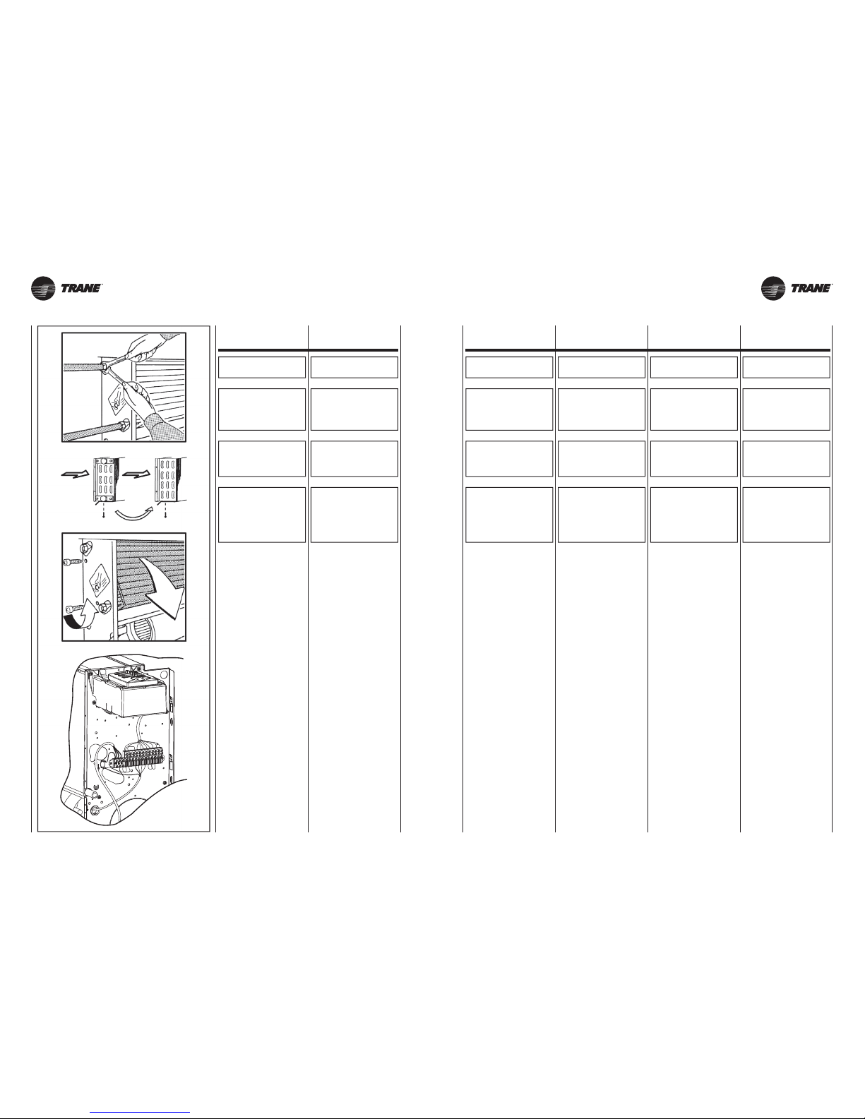
UNT-SVX26B-XX UNT-SVX26B-XX13 13A
COLLEGAMENTO
IDRAULICO
WATER
CONNECTIONS
RACCORDEMENTS
HYDRAULIQUES WASSERANSCHLUSS
CONEXIÓN
HIDRÁULICA
HYDRAULISCHE
AANSLUITING
PRESSIONE MASSIMA
DI ESERCIZIO: 1000 kPa.
MAXIMUM WORKING
PRESSURE: 1000 kPa.
PRESSION MAXI
DE SERVICE: 1000 kPa.
MAXIMALE
BETRIEBSDRUCK: 1000 kPa.
PRESIÓN MÁXIMA
DE OPERACIÓN: 1000 kPa.
MAXIMALE
BEDRIJFSDRUK: 1000 kPa.
USARE SEMPRE
CHIAVE E CONTROCHIAVE
PER L’ALLACCIAMENTO
DELLA BATTERIA
ALLE TUBAZIONI.
ALWAYS USE
TWO SPANNERS
TO CONNECT
THE HEAT EXCHANGER
TO THE PIPES.
UTILISER TOUJOURS
UNE CLE
ET UNE CONTRE-CLE
POUR LE RACCORDEMENT
DE LA BATTERIE
AUX TUYAUTERIES.
FÜR DEN ANSCHLUSS
DER BATTERIE
AN DIE ROHRLEITUNGEN
IMMER SCHLÜSSEL
UND GEGENSCHLÜSSEL
BENUTZEN.
USAR SIEMPRE
LLAVE Y CONTRALLAVE
PARA ENLAZAR
LA BATERÍA
A LAS TUBERÍAS.
GEBRUIK
STEEDS SLEUTELS
EN TEGENSLEUTELS
OM DE BATTERIJ
TE VERBINDEN
MET DE BUIZEN.
PREVEDERE SEMPRE
UNA VALVOLA
DI INTERCETTAZIONE
DEL FLUSSO IDRAULICO.
ALWAYS
FIT A GATE VALVE
IN THE WATER CIRCUIT.
PREVOIR TOUJOURS
UNE VANNE D’ARRET
DU FLUX HYDRAULIQUE.
IMMER EIN SPERRVENTIL
DES WASSERFLUSSES
INSTALLIEREN.
PREVER SIEMPRE
UNA VÁLVULA
DE ABRE-CIERRE
DEL FLUJO HIDRÁULICO
VOORZIE STEEDS EEN
RETOURKLEP.
NEL CASO
SI DEBBA INVERTIRE
IL LATO ATTACCHI
PROCEDERE
SECONDO LE SEGUENTI
ILLUSTRAZIONI:
TO REVERSE
THE CONNECTIONS SIDE,
PROCEED AS FOLLOWS:
DANS LE CAS OU L’ON
DEVRAIT INVERSER
LE COTE DES RACCORDS,
PROCEDER
COMME INDIQUE
SUR LES ILLUSTRATIONS
QUI SUIVENT.
FALLS DIE ANSCHLÜSSE
AUF DIE ANDERE
SEITE VERLEGT WERDEN
MÜSSEN,
WIE NACHSTEHEND
BESCHRIEBEN VORGEHEN.
SI SE DEBE INVERTIR
EL LADO
DE LAS CONEXIONES
PROCEDER SEGÚN
LAS ILUSTRACIONES
SIGUIENTES.
INDIEN DE AANSLUITINGEN
VAN ZIJDE MOETEN
WORDEN VERANDERD,
GAAT U TE WERK ZOALS
AANGEDUID
IN DE VOLGENDE
ILLUSTRATIES:
1 - Svitare le 4 viti di fissaggio
(2 per lato) della batteria
alla struttura e togliere la batteria.
2 - Sconnettere i cavi
di collegamento (prendendo nota
dei colori dei cavi). Svitare
le viti di fissaggio, e rimuovere
la morsettiera.
3 - Inserire la batteria
fissandola con le 4 viti.
4 - Fissare il quadro comandi
e la relativa morsettiera, nel lato
opposto a quello degli attacchi.
5 -
Per ripristinare i collegamenti
elettrici osservare le note prese,
aiutandosi con gli schemi elettrici.
1 - Undo the four screws
(two per side) fixing the coil
to the frame and remove the coil.
2 - Disconnect the wires
(taking note of the colour).
Undo the screws fixing
the terminal board and remove it.
3 - Replace the coil,
fixing it with the four screws.
4 - Fix the control unit and
terminal board on the opposite
side to the connections.
5 - Reconnect the electrical wires,
following the notes made
previously and referring
to the electrical wiring diagram.
1 - Dévisser les 4 vis
(2 par côté) fixant la batterie
à la structure et retirer la batterie.
2 - Déconnecter les câbles
de raccordement (en prenant
note des couleurs des câbles).
Dévisser les vis de fixation
et retirer le bornier.
3 - Insérer la batterie
à la fixant avec les 4 vis.
4 - Fixer le panneau de commande
et le bornier correspondant
sur le côté opposé à celui
des raccords.
5 - Pour refaire les branchements
électriques, consulter les notes
ayant été prises et les schémas
électriques.
1 - Die 4 Schrauben (2 pro Seite),
mit denen die Batterie
an der Struktur befestigt ist,
lösen und die Batterie abnehmen.
2 - Die Anschlusskabel
abhängen (dabei die Farben
der Kabel notieren). Die
Befestigungsschrauben lösen
und das Klemmenbrett
abnehmen.
3 - Die Batterie einsetzen und
mit den 4 Schrauben befestigen.
4 - Das Bedienfeld und das
entsprechende Klemmenbrett
an der gegenüberliegenden
Seite der Anschlüsse befestigen.
5 - Beim Wiederherstellen
der elektrischen Anschlüsse
die zuvor notierten Farben
beachten und die elektrischen
Schaltpläne zu Hilfe nehmen.
1 - Desenroscar los 4 tornillos
de fijación (2 por lado)
de la batería a la estructura
y retirar la batería.
2 - Desconectar los cables
de enlace (tomando nota
de los colores de los cables).
Desenroscar los tornillos
de fijación y retirar la borna
de conexión.
3 - Introducir la batería
asegurándola con los 4 tornillos.
4 - Asegurar el tablero de mandos
y la borna de conexión
correspondiente en el lado
opuesto al de las conexiones.
5 - Para restablecer los enlaces
eléctricos ajustarse
a cuanto apuntado previamente
y seguir los esquemas.
1 - Draai de 4 schroeven los
(2 aan weerszijden) die de batterij
aan de structuur bevestigen,
en verwijder de batterij.
2 - Koppel de aansluitingskabels
los (let op de kleur van
de kabels). Draai de
bevestigingsschroeven los
en verwijder het klemmenbord.
3 - Bevestig de batterij
met de 4 schroeven.
4 - Bevestig het bedieningspaneel
en het relatieve klemmenbord
aan de zijde tegenover
de aansluitingen.
5 - Om de elektrische
aansluitingen te herstellen,
raadpleeg de nota’s
en de elektrische schema’s.
Page 14
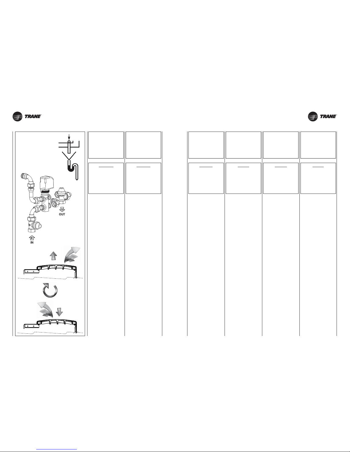
UNT-SVX26B-XX UNT-SVX26B-XX
2
3
1
14 14A
Nel caso l’apparecchio sia fornito di
valvola collegare i tubi di collegamento alla valvola stessa.
Se l’apparecchio è usato per raffreddare, per evitare gocciolamento di
condensa, isolare le tubazioni e la
valvola.
Nei periodi estivi e per lunghi periodi
di tempo con il ventilatore disinserito,
per evitare formazioni di condensa
all’esterno dell’apparecchio, si consiglia di intercettare l’alimentazione
della batteria.
Nel caso venga richiesta la vaschetta
supplementare, raccolta condensa,
questa va fissata alla struttura dal lato
attacchi e il tubo di scarico condensa
va collegato a quest’ultima.
Nelle versioni FVAE–FCAE è possibile invertire il flusso d’aria girando
la griglia, come da illustrazione.
If the unit is fitted with a valve, connect
the connection pipes to the valve.
If the unit is used for cooling, insulate
the pipes and valve to avoid drops of
condensate forming.
During the summer and when the fan
is inactive for long periods, you are
recommended to shut off the water
supply to the coil to avoid condensation
forming on the outside of the unit.
If a supplementary condensate drain
pan is used, this should be fixed to
the connections side of the frame and
the condensate drain pipe should be
fastened to the latter.
In the FVAE–FCAE versions, the air
flow can be reversed by rotating the
grill as illustrated.
Si l’appareil est équipé d’une vanne,
brancher les tuyauteries de raccordement à cette même vanne.
Si on utilise l’appareil pour rafraîchir,
isoler les tuyauteries et la vanne afin
d’éviter des égouttements de condensats.
Pendant l’été et lorsque le ventilateur
reste longtemps débranché, il est
conseillé d’isoler l’alimentation de la
batterie afin d’éviter les formations de
condensation à l’extérieur de l’appareil.
Si le bac supplémentaire (de récupération des condensats) est demandé,
il doit être fixé à la structure du côté
des raccords et le tuyau d’évacuation
des condensats doit être raccordé à
ce bac.
Dans les versions FVAE–FCAE, on
peut inverser le flux d’air en tournant
la grille (cf. illustration).
Falls das Gerät mit Ventil ausgestattet
ist, die Anschlussleitungen mit dem
Ventil verbinden.
Wenn das Gerät zum Kühlen benutzt
wird, müssen die Rohrleitungen und
das Ventil isoliert werden, um ein
Heraustropfen von Kondenswasser
zu vermeiden.
Im Sommer und wenn der Ventilator
für längere Zeit nicht benutzt wird,
empfiehlt sich, die Zuleitung zur Batterie
zu sperren, damit sich außen am Gerät
kein Kondenswasser bildet.
Falls eine zusätzliche Kondensatwanne verlangt wird, wird diese auf
der Anschlussseite an der Struktur
befestigt und die Kondensatablaufleitung wird daran angeschlossen.
Bei den Ausführungen FVAE–FCAE
kann der Luftstrom umgekehrt werden,
indem das Ausblasgitter wie auf der
Abbildung dargestellt umgedreht wird.
Si el aparato lleva válvula, conectar
los tubos de enlace con la propia
válvula.
Si se usa el aparato para enfriar, para
evitar goteos de condensado es preciso
aislar las tuberías y la válvula.
En las temporadas veraniegas y
cuando se prevea dejar apagado el
ventilador por mucho tiempo, para
evitar formaciones de condensado
al exterior del aparato se aconseja
interceptar el agua de alimentación
de la batería.
En el caso de que se requiera la pileta
suplementaria, de recogida del condensado, es preciso fijarla a la estructura
por el lado conexiones y el tubo de
descarga del condensado debe conectarse a esta última.
En las variantes FVAE–FCAE es posible invertir el flujo del aire girado la
rejilla, como mostrado en el dibujo.
Indien het apparaat uitgerust is met
een klep, sluit u de buizen rechtstreeks
aan op de klep.
Als het apparaat wordt gebruikt om
af te koelen, en om het druppelen van
condenswater te voorkomen, isoleert
u de buizen en de klep.
In de zomermaanden en indien de
ventilator lange tijd niet wordt gebruikt,
is het raadzaam de voeding van de
batterij te onderbreken, om de vorming
van condensatievocht aan de buitenkant
van het apparaat te voorkomen.
Als voor het opvangen van het
condensatievocht het gebruik van
een bijkomende opvangbak wordt
gevraagd, wordt deze bevestigd
aan de structuur, aan de zijde van
de aansluitingen; de afvoerbuis wordt
aangesloten aan deze laatste.
Voor de versies FVAE–FCAE kan
de luchtstroom worden omgedraaid
door het roostertje te draaien zoals
beschreven in de illustratie.
ATTENZIONE!
È CONSIGLIATO SIFONARE
LO SCARICO
DELLA CONDENSA,
INSTALLARE
IL TUBO
DI SCARICO CONDENSA
CON UNA PENDENZA
DI ALMENO 3 cm/metro.
IMPORTANT!
YOU ARE RECOMMENDED
TO FIT A SIPHON
ON THE CONDENSATE
DRAIN. INSTALL
A CONDENSATE
DRAIN PIPE
WITH A SLOPE OF
AT LEAST 3 cm/metre.
ATTENTION!
IL EST CONSEILLE DE
SIPHONER L’EVACUATION
DES CONDENSATS
ET D’INSTALLER LE TUYAU
D’EVACUATION
DES CONDENSATS
AVEC UNE PENTE
D’AU MOINS 3 cm/m.
ACHTUNG!
DER KONDENSATAUSLASS
SOLLTE MÖGLICHST MIT
EINEM SIPHON VERSEHEN,
UND DIE KONDENSAT-
ABLAUFLEITUNG
MIT EINER NEIGUNG VON
MINDESTENS 3 cm/Meter
INSTALLIERT WERDEN.
ATENCIÓN!
SE ACONSEJA COLOCAR
UN SIFÓN EN LA DESCARGA
DEL CONDENSADO,
INSTALAR EL TUBO
DE DESCARGA
DEL CONDENSADO
CON UNA PENDIENTE DE
POR LO MENOS 3 cm/metro.
OPGELET!
HET IS RAADZAAM
DE AFVOERBUIS VAN HET
CONDENSATIEVOCHT
TE HEVELEN,
EN DE AFVOERBUIS
TE INSTALLEREN MET EEN
HELLING VAN MINSTENS
3 cm/meter.
ATTENZIONE!
NEL CASO CI SIA
UNA SECONDA BATTERIA
DI SCAMBIO TERMICO
PROCEDERE
COME ILLUSTRATO
IN PRECEDENZA
SE SI DEVE CAMBIARE
IL LATO ATTACCHI.
IMPORTANT!
IF A SECOND
HEAT EXCHANGER COIL
IS FITTED, TO CHANGE
THE CONNECTIONS SIDE,
PROCEED AS
DESCRIBED PREVIOUSLY.
ATTENTION!
DANS LE CAS OU IL Y
AURAIT UNE DEUXIEME
BATTERIE D’ECHANGE
THERMIQUE,
PROCEDER COMME
INDIQUE PRECEDEMMENT
SI ON DOIT CHANGER
LE COTE DES RACCORDS.
ACHTUNG!
FALLS EINE ZWEITE
WÄRMETAUSCHER-
BATTERIE
VORHANDEN IST, GENAUSO
WIE OBEN BESCHRIEBEN
VORGEHEN, WENN DIE
ANSCHLUSSSEITE
VERLEGT
WERDEN MUSS.
ATENCIÓN!
SI HAY UNA SEGUNDA
BATERÍA
DE INTERCAMBIO TÉRMICO,
PROCEDER
COMO MOSTRADO
ANTERIORMENTE
SI ES PRECISO CAMBIAR
EL LADO
DE LAS CONEXIONES.
OPGELET!
INDIEN ER EEN TWEEDE
BATTERIJ VOOR DE WARM-
TEWISSELING IS, GAAT U TE
WERK ZOALS BESCHREVEN
IN BOVENSTAANDE
ILLUSTRATIE ALS DE ZIJDEN
VAN DE AANSLUITINGEN
MOETEN WORDEN
OMGEWISSELD.
Page 15
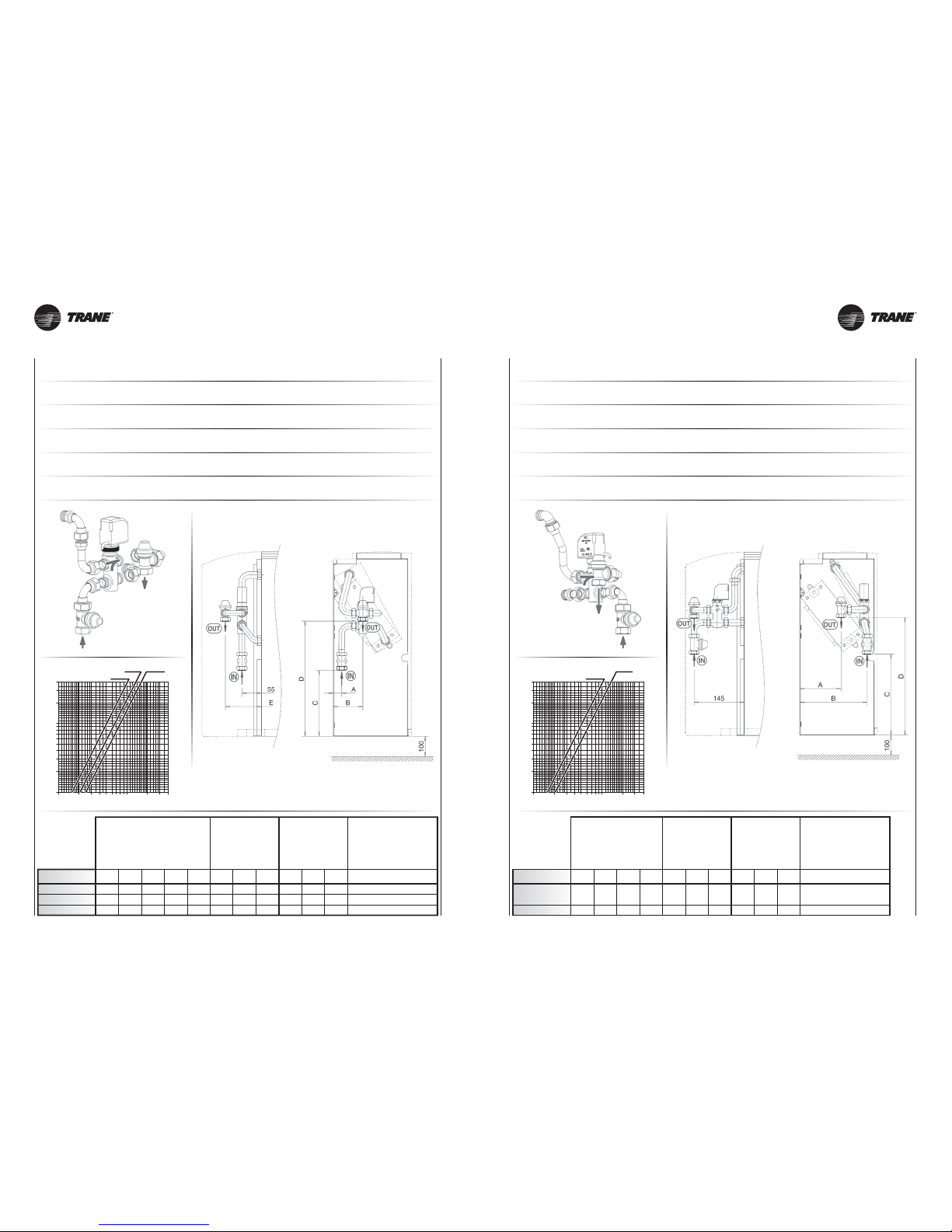
UNT-SVX26B-XX UNT-SVX26B-XX
40
30
20
10
9
8
7
6
5
4
3
2
1
100 200 300 400 600 800 1000 2000 3000 4000
Kvs 2 Kvs 2,5
Kvs 1,6
40
30
20
10
9
8
7
6
5
4
3
2
1
100 200 300 400 600 800 1000 2000 3000 4000
Kvs 2
Kvs 1,6
15 15A
Valvola a 3 vie per batteria principale
Valvola acqua a tre vie ON-OFF 230 V e kit di montaggio con detentore a regolazione micrometrica (accessorio optional).
Main battery 3 way valve
Control valve kit: 3 way valve, ON-OFF, with electric motor and mounting kit with regulating check valve (optional).
Vanne pour batterie principale
Vanne 3 voies (ON-OFF), 230V et kit de montage avec tés de réglage micrométrique (option).
3-Wege-Wasserventil für Hauptregister
3-Wege-Wasserventil ON-OFF 230 V mit elektrischem Motor und Montage KIT mit Reglerventil (optional).
Válvula para batería principal
Válvula agua de tres vías ON-OFF, con actuador eléctrico y kit de montaje (opción).
Klep voor hoofdbatterij
Driewegswaterklep ON-OFF, met elektrische bediening en montagekit (optioneel accessoire).
Valvola a 3 vie per batteria addizionale
Valvola acqua a tre vie ON-OFF 230 V e kit di montaggio con detentore a regolazione micrometrica (accessorio optional).
Auxiliary battery 3 way valve
Control valve kit: 3 way valve, ON-OFF, with electric motor and mounting kit with regulating check valve (optional).
Vanne pour batterie additionnelle
Vanne 3 voies (ON-OFF), 230V et kit de montage avec tés de réglage micrométrique (option).
3-Wege-Wasserventil für Zusatzregister
3-Wege-Wasserventil ON-OFF 230 V mit elektrischem Motor und Montage KIT mit Reglerventil (optional).
Válvula para batería adicional
Válvula agua de tres vías ON-OFF, con actuador eléctrico y kit de montaje (opción).
Klep voor hulp batterij
Driewegswaterklep ON-OFF, met elektrische bediening en montagekit (optioneel accessoire).
Codice
Code - Art. Nr. - Código
Non montata
Not fitted
À monter
Nicht Montiert
No montada
Niet gemonteerd
35169803-001
35169804-001
35169804-001
15
15
15
DN
1/2” F
1/2” F
1/2” F
(Ø)
2
2
2
Kvs
Dimensioni (mm)
Dimensions (mm)
Dimensions (mm)
Dimensionen (mm)
Dimensión (mm)
Afmetingen (mm)
Valvola
Valve
Vanne
Wasserventil
Válvula
Klep
15
20
20
DN
1/2”
3/4”
3/4”
(Ø)
1,6
2,5
2,5
Kvs
25
25
50
85
85
120
190
190
185
290
290
290
105
105
105
ABCDE
21-22-33-34
43-44-51-52
63-64
CASING
Detentore
Manual stop valve
Détenteur
Reduzierventil
Detentor
Houders
Codice
Code - Art. Nr. - Código
Non montata
Not fitted
À monter
Nicht Montiert
No montada
Niet gemonteerd
35169805-001
35169805-001
15
15
DN
1/2” F
1/2” F
(Ø)
2
2
Kvs
Dimensioni (mm)
Dimensions (mm)
Dimensions (mm)
Dimensionen (mm)
Dimensión (mm)
Afmetingen (mm)
Valvola
Valve
Vanne
Wasserventil
Válvula
Klep
15
15
DN
1/2”
1/2”
(Ø)
1,6
1,6
Kvs
120
135
195
200
240
235
340
330
ABCD
21-22-33-34
43-44-51-52
63-64
CASING
Detentore
Manual stop valve
Détenteur
Reduzierventil
Detentor
Houders
Dp - kPa
Portata acqua (l/h) - Water flow (l/h)
Débit d’eau (l/h) - Wasserdurchflussmenge (l/h)
Caudal de agua (l/h) - Waterdebiet (l/h)
TERRA - FLOOR - SOL
ERDE - TIERRA - AARDE
Dp - kPa
Portata acqua (l/h) - Water flow (l/h)
Débit d’eau (l/h) - Wasserdurchflussmenge (l/h)
Caudal de agua (l/h) - Waterdebiet (l/h)
TERRA - FLOOR - SOL
ERDE - TIERRA - AARDE
Page 16
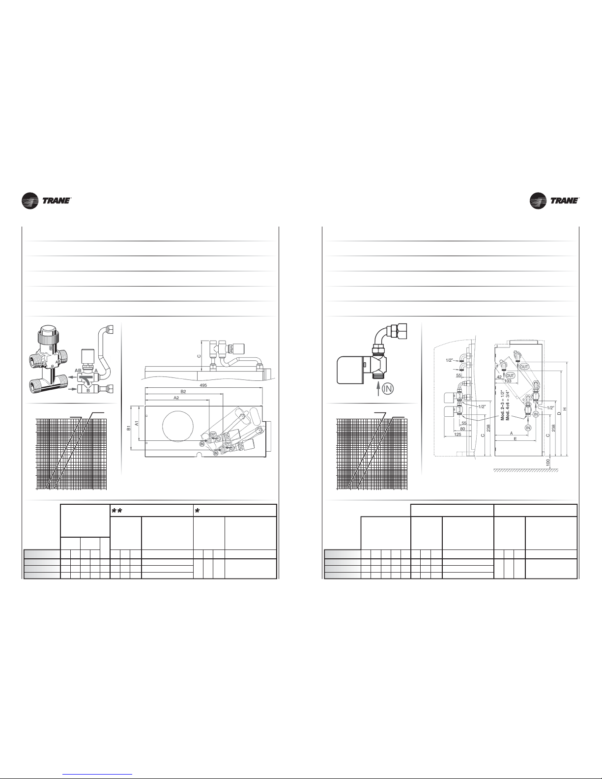
UNT-SVX26B-XX UNT-SVX26B-XX
Kvs 2,5
Kvs 1,6
40
30
20
10
9
8
7
6
5
4
3
2
1
100 200 300 400 600 800 1000 2000 3000 4000
Kvs 1,7
Kvs 2,8
40
30
20
10
9
8
7
6
5
4
3
2
1
100 200 300 400 600 800 1000 2000 3000 4000
16 16A
Valvola a 3 vie semplificata per batteria principale e addizionale (solo per unità FKAE)
Valvola acqua a tre vie ON-OFF 230 V e kit di montaggio senza detentore a regolazione micrometrica. Valvola con battuta piana (accessorio optional).
Simplified valve kit for 3 way valve (FKAE model only)
3 way valve, (ON-OFF) with electric motor and mounting kit. Valve with flat connection without micrometric lockshield valve (optional).
Vanne sans tés de réglage pour batterie principale ou additionnelle (seulement pour versions FKAE)
Vanne 3 voies (ON-OFF), 230V et kit de montage. Vannes avec raccordement à joint plat (option).
3-Wege-Wasserventil ohne Absperrungen (nur für Geräte FKAE)
3-Wege-Wasserventil ON-OFF 230 V und Montage-Kit. Ventil mit waagrechten Anschlüssen (optional).
Válvula de tres vías simplificada (solo para modelos FKAE)
Válvula agua de tres vías ON-OFF, 230 V y kit de montaje. Válvula con asiento plano (opción).
Simpele drievoudige klep 3 voor hoofdbatterij en extra batterij (alleen voor unit FKAE)
Driewegswaterklep ON-OFF 230 V en montagekit. Klep met vlakke verbinding (optioneel accessoire).
Valvola a 2 vie per batteria principale e addizionale
Valvola a 2 vie ON-OFF 230 V (accessorio optional).
2 way valve for main and additional coil
Control valve kit: 2 way valve, ON-OFF, with electric motor and mounting kit (optional).
Vanne pour batterie principale et batterie additionnelle
Vanne 2 voies (ON-OFF), avec servomoteur et kit de montage (option).
2-Wege-Wasserventil für Hauptregister und für Zusatzregister
2-Wege-Wasserventil ON-OFF 230 V mit elektrischem Motor und Montage KIT (optional).
Válvula para batería principal y adicional
Válvula eléctrica de dos vías ON-OFF, con actuador eléctrico y kit de montaje (opción).
Tweewegshoofdklep voor hoofdbatterij en extra batterij
Tweewegsklep ON-OFF 230 V (optioneel accessoire).
Dimensioni (mm)
Dimensions (mm)
Dimensions (mm)
Dimensionen (mm)
Dimensión (mm)
Afmetingen (mm)
Principale - Main - Principale
Haupt - Principal - Hoofd
Addizionale - Additional - Additionnelle
Zusatz - Adicional - Hulp
15 1/2” 1,7
35169906-001
15
20
20
1/2”
3/4”
3/4”
1,7
2,8
2,8
35169906-001
35169907-001
35169907-001
Non montata
Not fitted
À monter
Nicht Montiert
No montada
Niet gemonteerd
Valvola
Valve
Vanne
Wasserventil
Válvula
Klep
Codice
Code - Art. Nr. - Código
DN(Ø)Kvs
Non montata
Not fitted
À monter
Nicht Montiert
No montada
Niet gemonteerd
Valvola
Valve
Vanne
Wasserventil
Válvula
Klep
456
456
440
149
150
176
180
181
175
438
438
422
186
186
210
H
Codice
Code - Art. Nr. - Código
DN(Ø)Kvs
ACDE
21-22-33-34
43-44-51-52
63-64
CASING
Dimensioni (mm)
Dimensions (mm)
Dimensions (mm)
Dimensionen (mm)
Dimensión (mm)
Afmetingen (mm)
Principale - Main - Principale
Haupt - Principal - Hoofd
Addiz. - Additional - Additionnelle
Zusatz - Adicional - Hulp
B1 B2A1 A2
C
35169806-001
35169807-001
35169807-001
Codice
Code - Art. Nr. - Código
15
20
20
1/2”
3/4”
3/4”
1,6
2,5
2,5
DN(Ø)Kvs
15 1/2” 1,6
35169808-001
Codice
Code - Art. Nr. - Código
DN(Ø)Kvs
Valvola
Valve
Vanne
Wasserventil
Válvula
Klep
Non montata
Not fitted
À monter
Nicht Montiert
No montada
Niet gemonteerd
Non montata
Not fitted
À monter
Nicht Montiert
No montada
Niet gemonteerd
Valvola
Valve
Vanne
Wasserventil
Válvula
Klep
185
185
210
330
330
327
152
152
177
270
268
270
116
124
124
** *
21-22-33-34
43-44-51-52
63-64
CASING
Portata acqua (l/h) - Water flow (l/h)
Débit d’eau (l/h) - Wasserdurchflussmenge (l/h)
Caudal de agua (l/h) - Waterdebiet (l/h)
Dp - kPa
Portata acqua (l/h) - Water flow (l/h)
Débit d’eau (l/h) - Wasserdurchflussmenge (l/h)
Caudal de agua (l/h) - Waterdebiet (l/h)
TERRA - FLOOR - SOL
ERDE - TIERRA - AARDE
Dp - kPa
Page 17
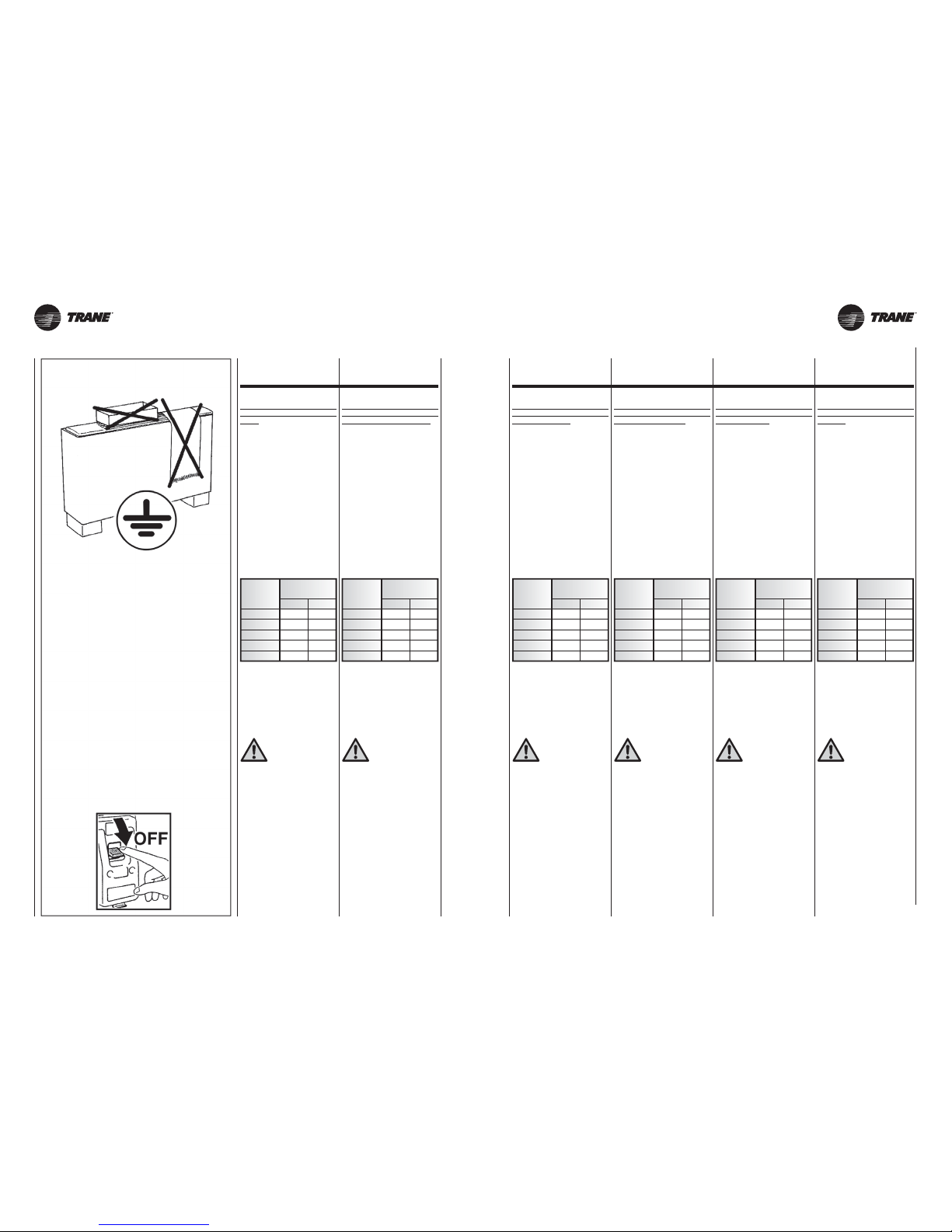
UNT-SVX26B-XX UNT-SVX26B-XX
Nel caso
di abbinamento
del Ventilconvettore
con regolatori elettronici
occorre tenere assolutamente
in considerazione che il segnale
0-10Vdc proverrà sempre e solo
dal regolatore stesso e che dovrà
essere applicato sulla struttura
del ventilconvettore.
A monte dell’unità prevedere un interruttore onnipolare con distanza
minima dei contatti di 3,5 mm.
Occorre sempre effettuare la messa
a terra dell’unità.
Togliere sempre l’alimentazione elettrica prima di accedere alla macchina.
La sezione minima dei conduttori
è 0.75 mm
2
If the fan coil
is used with
electronic controllers,
the 0-10Vdc signal
must always be supplied
by the same controller, which
must be located
on the inner casing.
Upstream of the unit, fi t an omnipolar
switch with minimum contact distance
of 3,5 mm.
The unit must always be earthed.
Always disconnect the electrical power
supply before opening the unit.
The minimum cross section of the
electric wires is 0.75 mm
2
En cas
d’association
du ventilo-convecteur
avec des régulateurs électroniques, il faut absolument garder
à l’esprit que le signal 0-10Vdc
proviendra toujours et
uniquement du régulateur même,
et qu’il devra être appliquée
sur le structure interne.
En amont de l’unité prévoir un interrupteur unipolaire avec distance
minimum des contacts de 3,5 mm.
Il faut toujours effectuer la mise à la
terre de l’unité.
Débrancher toujours la machine avant
d’y accéder.
La section minimum des conducteurs est 0.75 mm
2
Wenn der
Gebläse-Konvektor
mit elektronischen
Reglern ausgerüstet ist,
ist unbedingt zu berücksichtigen,
dass das 0-10VDC-Signal
stets ausschließlich
vom Regler selbst stammen
kann und muss auf dem
innenteil befindet.
Dem Gerät einen allpoligen Schalter
mit einer Kontaktöffnung von mindestens
3,5 mm vorschalten.
Das Gerät vorschriftsmäßig erden.
Vor dem Zugriff auf das Geräteinnere stets
die Spannungsversorgung unterbrechen.
Der Mindestquerschnitt der Leiter
beträgt 0.75 mm
2
En caso
de conexión
de Ventiloconvector
con reguladores electrónicos
debe tenerse absolutamente
en cuenta que la señal 0-10Vdc
procederá siempre y sólo
del regulador y que deberá
ponerse en la estructura interna.
Prever, más arriba de la unidad, un
interruptor omnipolar con una distancia
mínima de los contactos de 3,5mm.
Realizar siempre la toma de tierra de
la unidad.
Retirar siempre la corriente eléctrica
antes de acceder a la máquina.
La sección mínima de los conductores es de 0.75 mm
2
In het geval van
combinering van de
Ventilator-convector
met elektronische regulators
dient er absoluut aan gedacht te
worden dat het signaal 0-10Vdc
altijd en alleen afkomstig zal zijn
van de regulator zelf en
dat deze binnenin het schakelbord
geplaatst zal moeten zijn.
Stroomopwaarts van de eenheid moet
een veelpolige schakelaar voorzien
worden met een minimale afstand
tussen de klemmen van 3,5mm.
De eenheid moet in elk geval geaard
worden.
Koppel het apparaat altijd los van het
elektricitietsnet alvorens er aan te werken.
De minimale doorsnede van de
geleiders bedraagt 0,75 mm
2
17 17A
COLLEGAMENTI
ELETTRICI
Prescrizioni generali
Effettuare i collegamenti elettrici secondo le leggi e le norme nazionali
vigenti.
Gli schemi elettrici non prendono in
considerazione la messa a terra o altri tipi di protezione elettrica previsti da
norme, regolamenti, codici e standard
locali o dall’azienda locale di fornitura
dell’energia elettrica.
Prima di installare il ventilconvettore
verificare che la tensione nominale
di alimentazione sia di 230V - 50 Hz.
L’alimentazione elettrica è sempre
collegata ai morsetti L, N e PE della
scheda.
La potenza massima assorbita per il
funzionamento alla tensione di 230 V
c.a. è indicata nella tabella seguente:
Assicurarsi che l’impianto elettrico sia
adatto ad erogare, oltre alla corrente
di esercizio richiesta dal ventilconvettore, anche la corrente necessaria per
alimentare elettrodomestici ed apparecchi già in uso.
ELECTRICAL
CONNECTIONS
General instructions
Perform electrical connections in
accordance with laws and regulations
in force in the country concerned.
The wiring diagrams do not address
protective grounding or other electrical
protection which will be required under
local rules, regulations, codes and
standards or by the local electricity
supplier.
Before installing the fan coil, make
sure the rated voltage of the power
supply is 230V - 50 Hz.
The power supply is always connected
to terminals L, N and PE on the board.
Maximum power consumption for
230 VAC mains power operation is
as follows:
Make sure that, in addition to supplying
the working current required by the
fan coil, the mains electrical supply
is also able to supply the current
necessary to operate other household appliances and units.
BRANCHEMENTS
ELECTRIQUES
ELEKTROANSCHLÜSSE
CONEXIÓNES
ELECTRICAS
ELEKTRISCHE
AANSLUITINGEN
Instructions
Effectuer les branchements électriques
selon la législation et les normes
nationales en vigueur.
Les schémas électriques ne prennent
pas en considération la mise à la terre ou
d’autres types de protection électrique
prévus par les normes, réglements,
législation et standards locaux ou du
fournisseur d’énergie électrique.
Avant d’installer le ventilo-convecteur
vérifier que la tension d’alimentation
nominale est de 230V – 50Hz.
L’alimentation électrique est toujours
raccordée aux bornes L, N et PE de
la carte.
La puissance maximale absorbée
pour le fonctionnement à la tension
de 230 V c.a est indiquée dans le
tableau suivant:
S’assurer que la puissance de l’installation électrique est suffisante pour
fournir le courant de marche pour le
ventilo-convecteur ainsique le courant
nécessaire pour alimenter les électroménagers et les appareils déjà utilisés.
Allgemeine Anweisungen
Die Elektroanschlüsse müssen gemäß
den einschlägigen nationalen Gesetzen
und Normen erstellt werden.
Die Schaltpläne beinhalten nicht die
Erdung oder andere, in den örtlichen
Normen, Bestimmungen, Gesetzen
und Standards, oder vom örtlichen
Energieversorgungsunternehmen
vorgesehenen elektrische Schutzarten.
Vor der Installation des Klimakonvektors
muss sichergestellt werden, dass die
nominale Versorgungsspannung 230V
- 50 Hz beträgt.
Die Spannungsversorgung ist immer an
die Klemmen L, N und PE der Platine
angeschlossen.
Die max. Leistungsaufnahme bei
Betrieb mit einer Spannung von 230 V
Wechselstrom ist in der folgenden
Tabelle angeführt:
Sicherstellen, dass die Elektroanlage
in der Lage ist, neben dem Klimakonvektor auch die anderen Haushaltsgeräte zu versorgen.
Prescripciones generales
Efectuar las conexiones eléctricas de
acuerdo con las leyes y las normativas
nacionales vigentes.
Los esquemas eléctricos no tienen en
cuenta la toma de tierra u otros tipos de
protección eléctrica previstos por las
normas, reglamentos, códigos y estándares locales o de la empresa local
de suministro de la energía eléctrica.
Antes de instalar el ventilador convector
verificar que la tensión nominal de alimentación sea de 230 V - 50 Hz.
La alimentación eléctrica siempre está
conectada a los bornes L, N y PE de
la tarjeta.
La máxima potencia absorbida para
el funcionamiento a la tensión de 230 V
c.a. se indica en la tabla siguiente:
Asegurarse de que la instalación eléctrica sea apta para distribuir, además
de la corriente de ejercicio requerida
por el ventilador convector, la corriente
necesaria para alimentar electrodomésticos que ya se estuvieran usando.
Algemene voorschriften
Voer de elektrische aansluitingen
uit volgens de geldende nationale
wetgeving.
De schakelschema’s houden geen
rekening met de aardleiding of andere
soorten van elektrische beveiliging
voorzien door de lokale normen, regels
en standaards of het lokaal bedrijf dat
de elektrische energie levert.
Alvorens de ventilator-convector te
installeren, controleer of de nominale
voedingsspanning 230V - 50 Hz
bedraagt.
De elektrische voeding wordt altijd
aangesloten op de klemmen L, N en
PE van de schakeling.
Het maximaal opgenomen vermogen
voor de werking bij een spanning van
ca. 230V is aangegeven in de volgende
tabel:
Zorg ervoor dat de elektrische installatie
geschikt is voor het leveren van de
door de ventilator-convector gevraagde
bedrijfsstroom en de stroom die nodig
is voor het voeden van de huishoudelijke apparatuur en reeds in gebruik
zijnde toestellen.
CASING
21-22
33
-
34
43
-
44
51
-
52
63
-
64
20,5
25,0
32,0
41,0
99,0
0,18
0,22
0,28
0,34
0,81
ASSORBIMENTO
TOTALE
WA
CASING
21-22
33
-
34
43
-
44
51
-
52
63
-
64
20,5
25,0
32,0
41,0
99,0
0,18
0,22
0,28
0,34
0,81
TOTAL
ABSORBTION
WA
CASING
21-22
33
-
34
43
-
44
51
-
52
63
-
64
20,5
25,0
32,0
41,0
99,0
0,18
0,22
0,28
0,34
0,81
CONSOMMATION
TOTAL
WA
CASING
21-22
33
-
34
43
-
44
51
-
52
63
-
64
20,5
25,0
32,0
41,0
99,0
0,18
0,22
0,28
0,34
0,81
STROMAUFNAHME
WA
CASING
21-22
33
-
34
43
-
44
51
-
52
63
-
64
20,5
25,0
32,0
41,0
99,0
0,18
0,22
0,28
0,34
0,81
ABSORCIÓN TOTAL
WA
CASING
21-22
33
-
34
43
-
44
51
-
52
63
-
64
20,5
25,0
32,0
41,0
99,0
0,18
0,22
0,28
0,34
0,81
VERMOGEN
WA
Page 18
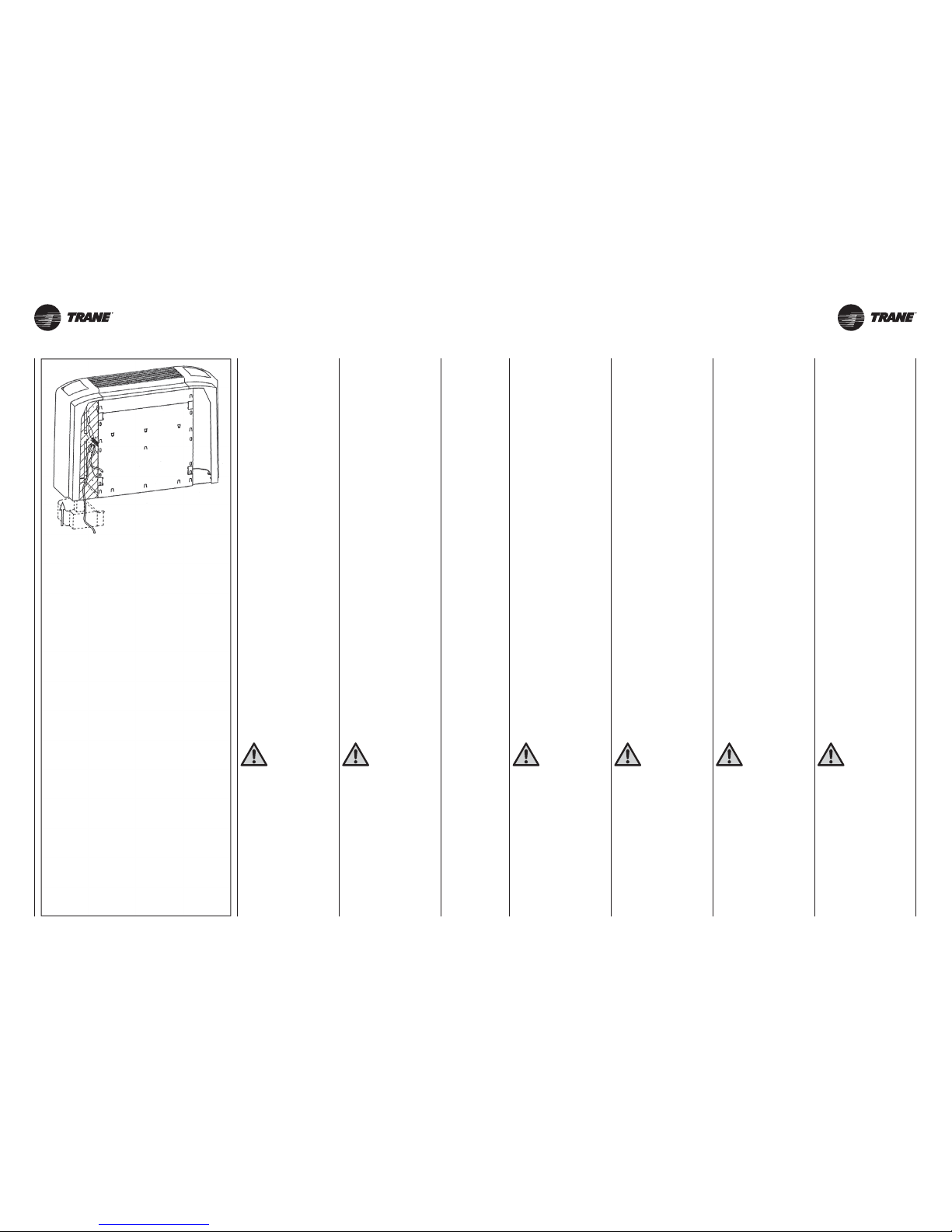
UNT-SVX26B-XX UNT-SVX26B-XX18 18A
Indicazioni
per il collegamento
L’apparecchio è equipaggiato di una
morsettiera di collegamento posta
sulla fiancata interna, lato opposto
attacchi idraulici. Il collegamento deve essere effettuato rispettando gli
schemi elettrici riportati sul presente
libretto.
L’installatore dovrà prevedere l’ingresso dei cavi di collegamento utilizzando gli accessi previsti, ovvero:
• da muro utilizzando l’apertura posteriore resa disponibile in corrispon-
denza della fiancata.
• da pavimento utilizzando il vano in
corr ispondenza del piedino (solo
apparecchi FVAE con piedini).
•
comunque in prossimità dell’apparecchio, nel caso di versioni ad incasso.
Tutti i comandi per installazione a bordo macchina sono dotati di morsettiera con spinotti predisposti per un collegamento rapido. Una volta accoppiata questa morsettiera alla corrispettiva morsettiera presente sulla fiancata, serrare adeguatamente le viti dei
singoli morsetti per garantire il corretto contatto elettrico. La non ottemperanza di questa prescrizione causa
una grave condizione di pericolo.
Connection instructions
The unit is fitted with a connection
terminal board on the internal side
panel on the opposite side to the
hydraulic couplings. To connect, respect
the wiring diagrams in this booklet.
The installer must bring the connecting
wires into the unit through the access
points provided:
•
wall-mounted, using the rear access
point corresponding to the side
panel.
• floor-standing, using the recess
inside the foot (FVAE units with
feet only).
• from near the unit in the case of
built-in installations.
All controls for installation on the unit
are provided with a terminal board with
plugs for rapid connection. Connect
this terminal board to the corresponding
board on the side panel, then tighten
the screws on the individual terminals
to guarantee correct electrical contact.
Failure to follow this instruction could
cause serious risks.
Indications
pour le raccordement
L’appareil est équipé d’un bornier de
raccordement placé sur le côté intérieur,
du côté opposé aux raccords hydrauliques.
Le raccordement doit être effectué en
respectant les schémas électriques
donnés dans cette notice.
L’installateur devra prévoir l’entrée des
câbles de raccordement en utilisant
les accès prévus, c’est-à-dire:
• sur le mur en utilisant l’ouverture
postérieure disponible près du côté.
• au sol à travers le pied (seulement
appareils FVAE avec pieds).
• toujours à proximité de l’appareil,
dans le cas de versions à encastrer.
Toutes les commandes à installer à
bord de la machine sont munies d’un
bornier avec des bornes à branchement rapide. Quand ce bornier est
raccordé au bornier correspondant
placé sur le côté, serrer les vis de
chaque bornier pour garantir un bon
contact électrique. Ne pas se conformer
à cette prescription pourrait causer un
grave danger.
Anleitungen
für den Anschluss
Das Gerät ist mit einer Anschlussklemmleiste ausgestattet, die an der
inneren Seitenwand, gegenüber den
Wasseranschlüssen untergebracht ist.
Für den Anschluss müssen die in
dieser Betriebsanleitung enthaltenen
Schaltpläne befolgt werden.
Der Installateur muss die Durchgänge der
Anschlusskabel an den vorhergesehenen
Stellen ausführen, und zwar:
•
Von der Wand her unter Verwendung
der hinteren Öffnung auf Höhe der
Seitenwand.
• Vom Boden her unter Verwendung
des Hohlraums im Innern des Fußes
(nur bei den Geräten FVAE mit Füßen).
• bei Einbaugeräten in jedem Fall in
der Nähe des Geräts.
Alle am Gerät zu installierenden
Steuerungen sind mit Klemmleiste mit
Steckerstiften für den problemlosen
Anschluss ausgestattet. Nachdem die
Steckerklemmleiste mit der entsprechenden
Buchsenklemmleiste an der Seitenwand
verbunden ist, die Schrauben der einzelnen
Klemmen fest anziehen, damit der
elektrische Kontakt gewährleistet wird.
Die Unterlassung dieser Vorschrift kann
schwerwiegende Gefahrensituationen
verursachen.
Indicaciones
para la conexión
El aparato está equipado con una caja
de bornes de conexión situada en el
lateral interno, en el lado opuesto a las
conexiones hidráulicas. La conexión
se tiene que realizar respetando los
esquemas eléctricos que figuran en
el presente manual.
El instalador deberá prever la entrada
de los cables de conexión usando los
accesos previstos, es decir:
• desde la pared usando la apertura
posterior disponible en el lateral.
• desde el suelo usando la abertura
existente bajo el pie (sólo para los
aparatos FVAE con pies).
•
de cualquier forma cerca del aparato,
en el caso de versiones empotradas.
Todos los mandos que se instalarán
en la máquina estarán provistos de
caja de bornes con clavijas preparadas
para una conexión rápida. Una vez que
esta caja de bornes esté acoplada a la
caja de bornes correspondiente situada
en el lateral, apretar adecuadamente
los tornillos de cada borne para garantizar un contacto eléctrico correcto.
El no observar esta prescripción puede
ocasionar un gran riesgo.
Aanwijzingen
voor de aansluiting
Het apparaat is uitgerust met een
aansluitklemmenbord dat zich aan
de binnenkant bevindt, op de wand
tegenover de hydraulische aansluitingen.
De aansluiting dient te worden uitgevoerd
conform de schakelschema’s in deze
handleiding.
De monteur zal een kabelingang moeten
verwezenlijken door de toegangen die
voorzien werden te gebruiken, d.w.z.:
• aan de muur door de beschikbare
opening achteraan te gebruiken,
overeenstemmend met de zijkant.
•
aan de grond door de holte in overeenstemming met het voetje te gebruiken
(alleen FVAE-toestellen met voetje).
• in elk geval in de nabijheid van het
apparaat, voor ingepaste versies.
Al de bedieningen voor de installatie
aan boord, zijn voorzien van een
klemmenbord met pennen voor een
vlugge verbinding. Wanneer het
klemmenbord aan het overeenkomstige
klemmenbord op de zijkant gekoppeld
is, de schroeven van de klemmen
aanspannen om het correct elektrisch
contact te verzekeren. Dit voorschrift
niet naleven, kan zeer gevaarlijk zijn.
Dotazione elettrica
Il motore è protetto da un termocontatto integrato dell’avvolgimento che
arresta il motore in caso di surriscaldamento e lo riavvia automaticamente dopo che si è raffreddato.
La scheda è dotata di una morsettiera
per il collegamento dell’alimentazione, per la gestione delle velocità, per
il controllo delle valvole e per il collegamento del dispositivo di sicurezza.
Electrical Equipment
The motor is protected by a thermal
contact integrated in the winding. It
stops the motor if overheating occurs and
starts the motor again automatically
after it has cooled down.
The fan coil is provided with a terminal
board for the connection of the electrical
feeding, for the fan speed control, for
the valve’s control and for the connection
with the safety device.
Équipement électrique
Le moteur est protégé par un thermocontact placé directement sur la bobine
qui arrête le moteur en cas de surchauffe
et le remet en marche automatiquement
quand il est refroidi.
La carte est munie d’un bornier pour
le raccordement de l’alimentation, pour
la gestion des vitesses, pour le contrôle
des vannes et pour le raccordement
du dispositif de sécurité.
Elektroausstattung
Der Motor wird durch einen in die Wicklung
integrierten Thermokontakt geschützt,
welcher den Motor bei Überhitzung
ausschaltet, und nach dem Abkühlen
automatisch wieder einschaltet.
Die Platine ist mit einer Klemmleiste
für den Anschluss der Einspeisung, die
Verwaltung der Drehzahl, die Kontrolle
der Ventile und den Anschluss der Sicherheitsvorrichtung ausgestattet.
Dotación eléctrica
El motor está protegido por un termocontacto integrado del bobinado que para
al motor en caso de sobrecalentamiento
y lo vuelve a poner en marcha automáticamente una vez que se ha enfriado.
La tarjeta está provista de una caja de
bornas para la conexión de la alimentación, para la gestión de la velocidad,
para el control de las válvulas y para la
conexión de dispositivo de seguridad.
Bijgeleverde elektrische
inrichtingen
De motor is beschermd door een
ingebouwd thermocontact dat de motor
stillegt ingeval van oververhitting.
De
motor wordt weer gestart nadat
hij
afgekoeld is.
De schakeling is voorzien van een
klemmenbord voor de aansluiting van
de voeding, het beheer van de snelheden,
de controle van de kleppen en de aansluiting
van de veiligheidsinrichting.
Nella progettazione
e dimensionamento
della linea
di alimentazione e delle protezioni
per apparecchiature elettroniche
dotati di filtri anti-disturbo
è necessario considerare i valori
di dispersione in corrente
verso terra (leakage current).
I nostri apparecchi ECM
risultano conformi ai limiti imposti
dalla normativa CEI-EN 60335
avendo un valore di dispersione
di 0.8 mA, inferiore al valore limite
di 3.5 mA ammesso ed imposto
dalla norma.
Il valore totale di dispersione deve essere considerato in funzione del numero di apparecchi installati e delle
caratteristiche delle eventuali altre apparecchiature elettriche collegate su
di una stessa linea elettrica.
When designing
and dimensioning
the power line
and protection devices for electronic
appliances with interference
suppression filters, the leakage
current must be taken into
consideration.
Our ECM appliances comply
with CEI-EN 60335 as they have
a leakage current of 0.8 mA,
below the 3.5 mA permitted limit
specified in the standard.
The total leakage current considered
must take account of the number of
appliances installed and the characteristics
of any other electrical appliances
connected on the same power line.
Lors de la conception
et du dimensionnement
de la ligne d’alimentation
et des protections pour
les appareils électroniques munis
de filtres anti-parasites
il est nécessaire de tenir compte
des valeurs de courant de fuite
à la terre.
Nos appareils ECM sont
conformes aux limites imposées
par la norme CEI-EN 60335
puisqu’ils ont une valeur de fuite
de 0.8 mA, inférieure à la valeur limite
de 3,5 mA admise et imposée
par la norme.
Le courant total de fuite doit être calculé
en fonction du nombre d’appareils
installés et des caractéristiques des
autres appareils électriques éventuellement branchés sur la même ligne
électrique.
Bei Auslegung
und Bemessung
der Zuleitung und
der Sicherheitseinrichtungen
für elektronische Geräte
mit Entstörfilter sind die Werte
des Ableitstroms zu berücksichtigen.
Unsere Geräte ECM entsprechen
den von der Norm CEI-EN 60335
auferlegten Grenzen und weisen
einen Leckstrom von 0.8 mA auf,
der unter dem von der Norm
vorgeschriebenen zulässigen
Grenzwert von 3.5 mA liegt.
Der Gesamtwert des Leckstroms ist
je nach Anzahl der installierten Geräte
und der eventuellen anderen, an derselben
Stromleitung angeschlossenen Elektrogeräte zu berücksichtigen.
En el diseño
y dimensionamiento
de la línea de
alimentación y de las protecciones
para equipos electrónicos
dotados de filtros antiparasitarios
se han de considerar
los valores de corriente de fuga.
Nuestros aparatos ECM
cumplen los límites dictados
por la normativa CEI-EN 60335,
presentan un valor de corriente
de fuga de 0.8 mA, inferior
al valor límite de 3.5 mA admitido
e impuesto por la norma.
El valor total de corriente de fuga ha
de considerarse en función del número
de aparatos instalados y de las características de otros posibles equipos
eléctricos conectados a una misma
línea eléctrica.
Bij het ontwerp en
de dimensionering
van de voedingsleiding
en de beveiligingen voor
elektronische apparatuur voorzien
van storingsfilters moeten
de waarden voor de lekstroom
naar aarde in beschouwing
worden genomen.
Onze ECM apparaten voldoen aan
de limieten vereist door de norm
CEI-EN 60335, aangezien ze een
lekwaarde van 0.8 mA hebben,
die lager is dan de limietwaarde
van 3.5 mA die door deze norm
wordt toegestaan en vereist.
De totale lekwaarde moet in beschouwing
worden genomen op basis van het aantal
geïnstalleerde apparaten en de kenmerken van eventuele andere elektrische
apparatuur die op dezelfde elektriciteitsleiding is aangesloten.
Page 19
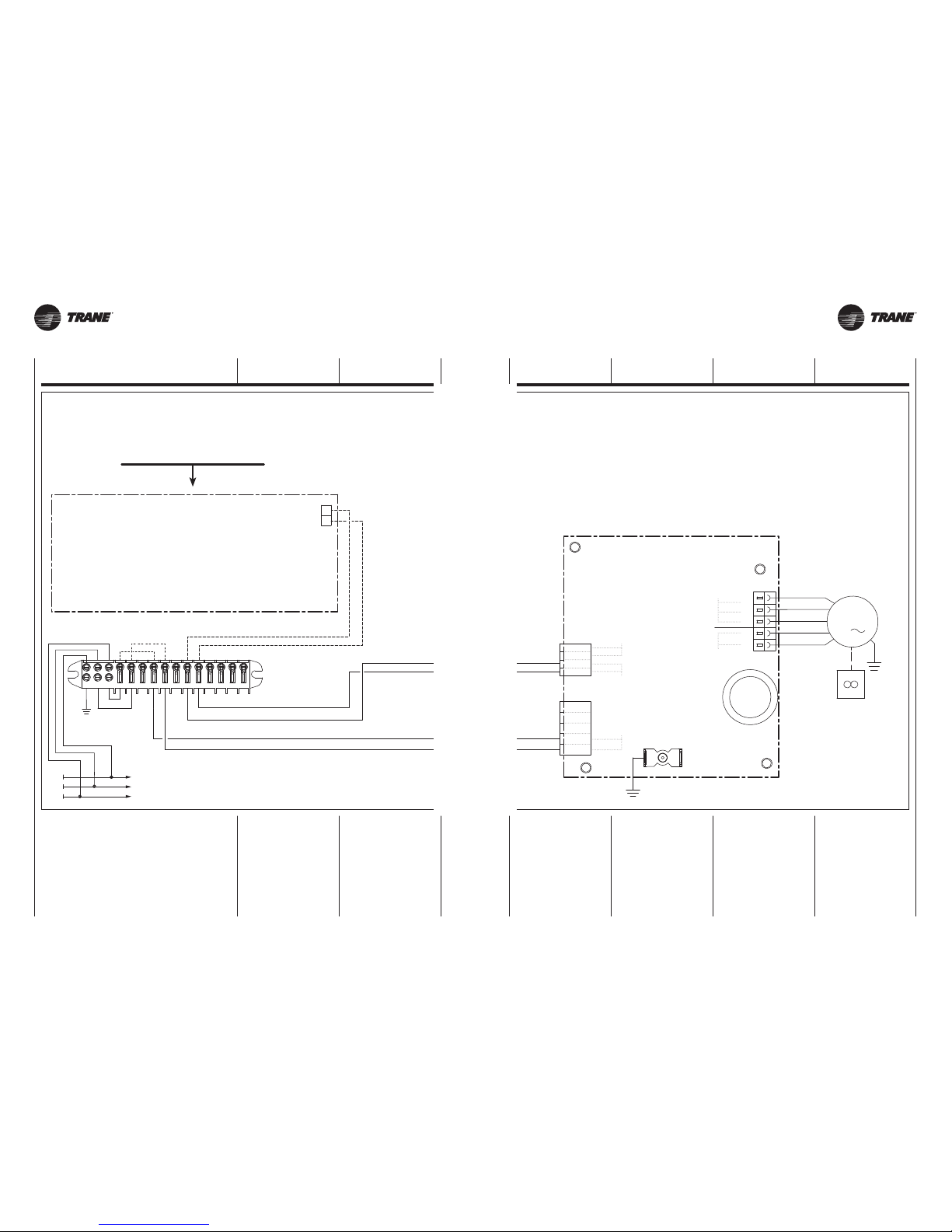
UNT-SVX26B-XX UNT-SVX26B-XX
0Vdc
10Vdc
L
N
PE
NLPE
13
10 121411
15
798
546
MFC
PE
CONTROLLER
Segnale / Signal / Signal
Signal / Señal / Signaal
Impedenza / Impedance / Impédance
Impedanz / Impedancia / Impedantie
< 100 1
0,3/13V
V < 0,9 Volt
10 Volt
Fan OFF con / Fan OFF with / Ventilateur OFF avec
Ventilator OFF mit / Ventilador OFF con / Fan OFF met
Velocità massima / Maximum speed / Vitesse maximale
Höchstgeschwindigkeit / Máxima velocidad / Maximale snelheid
ECM BLAC board
PE
L
N
10V
0V
DFS+
DFS-
U
V
W
T1
T1
PE
M
PE
3
U / V / W
T1
0-10Vdc
ECM
DFS-/DFS+
WH
RD
BK
BU
WH
RD
BK
BU
19 19A
SCHEDA ECM
ECM
ELECTRONIC BOARD
BORNIER ECM
ELEKTRONIKPLATINE
ECM TARJETA ECM SCHAKELING ECM
LEGENDA Scheda BLAC:
BLAC =
Scheda
elettronica Inverter
T1 =
Collegamento
protezione termica motore
0-10Vdc = Segnale ingresso
U/V/W = Collegamento motore
DFS-/DFS+ = Segnal digitali
CONTROLLER = Regolatore
WH = Bianco
RD = Rosso
BK = Nero
BU = Blu
BLAC Board LEGEND:
BLAC = Inverter circuit board
T1 = Motor fan
thermal protector connection
0-10Vdc = Input signal
U/V/W = Motor fan connection
DFS-/DFS+ =
Digital fault signals
CONTROLLER = Controller
WH = White
RD = Red
BK = Black
BU = Dark Blue
LÉGENDE Carte BLAC:
BLAC = Carte
électronique de contrôle
T1 =
Raccordement
protection ther mique moteur
0-10Vdc = Signal
U/V/W =
Raccordement moteur
DFS-/DFS+ =
Signaux numériques
CONTROLLER = Régulateur
WH = Blanc
RD = Rouge
BK = Noir
BU = Bleu foncé
LEGENDE Karte BLAC:
BLAC = Elektronikkarte Inverter
T1 = Anschluss
Motorwärmeschutzschalter
0-10Vdc = Signal
U/V/W = Motoranschluss
DFS-/DFS+ = Digitalsignale
CONTROLLER = Regler
WH = Weiß
RD = Rot
BK = Schwarz
BU = Blau
LEYENDA Tarjeta BLAC:
BLAC = Tarjeta
electrónica Inversor
T1 = Conexión
protección térmica motor
0-10Vdc = Señal
U/V/W = Conexión motor
DFS-/DFS+ = Señales digitales
CONTROLLER = Regulador
WH = Blanco
RD = Rojo
BK = Negro
BU = Azul
LEGENDE Kaart BLAC:
BLAC = Elektronische kaart
inverter
T1 = Verbinding thermische
bescherming motor
0-10Vdc = Signaal
U/V/W = Verbinding motor
DFS-/DFS+ = Digitale signalen
CONTROLLER = Regulator
WH = Witte
RD = Rood
BK = Zwart
BU = Donkerblauw
Accessorio non incluso
Not included accessories
Accessoires non inclus
Zubehör nicht im Preis enthalten
Accessorios no incluidos
Accessoires niet inbegrepen
Page 20
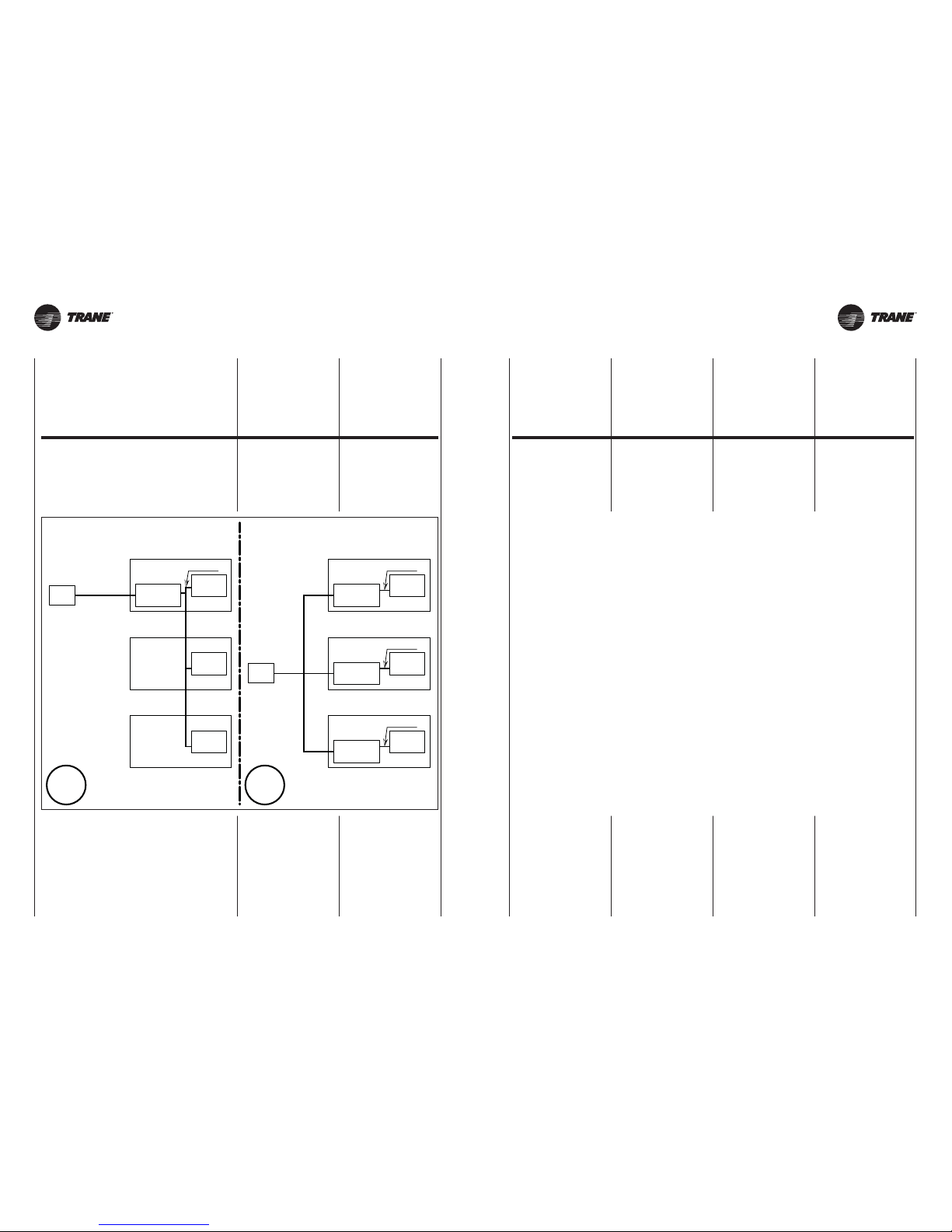
UNT-SVX26B-XX UNT-SVX26B-XX20 20A
LEGENDA:
PC = Pannello comandi
CONTROLLER = Regolatore
BLAC =
Scheda
elettronica Inverter
0-10Vdc = Segnale ingresso
Ciascuna unità INVERTER
dovrà recepire segnale 0-10Vdc
con provenienza interna al quadro
di derivazione. Pertanto non sarà
possibile derivare da un regolatore
il medesimo segnale a comando
di più unità ventilconvettore.
LEGEND:
PC = Control panel
CONTROLLER = Controller
BLAC = Inverter circuit board
0-10Vdc = Input signal
Each INVERTER unit
should receive a 0-10Vdc signal
from inside the shunt panel.
Therefore it is not possible to shunt
the same signal from a controller
to control multiple fan coil units.
LÉGENDE:
PC = Panneau commandes
CONTROLLER = Régulateur
BLAC = Carte
électronique de contrôle
0-10Vdc = Signal
Chaque unité ONDULEUR
devra recevoir le signal 0-10Vdc
avec provenance à l’intérieur
du tableau de dérivation. Il ne sera
donc pas possible de dériver
à partir d’un régulateur le même
signal à commande de plusieurs
unités de ventilo-convecteurs.
LEGENDE:
PC = Schalttafel
CONTROLLER = Regler
BLAC = Elektronikkarte Inverter
0-10Vdc = Signal
Jede Einheit INVERTER
muss das aus dem Abzweigschrank
kommende Signal 0-10Vdc
aufnehmen. Deshalb kann dasselbe
Signal zur Steuerung mehrerer
Kassetten-Klimakonvektore
nicht von einem Regler abgezweigt
werden.
LEYENDA:
PC = Panel de mandos
CONTROLLER = Regulador
BLAC = Tarjeta
electrónica Inversor
0-10Vdc = Señal
Cada unidad INVERSOR tendrá
que recibir una señal de 0 a 10Vdc
suministrado internamente
al cuadro de derivación. Por lo tanto
no será posible derivar
de un regulador la misma señal
de mando de varias unidades
ventilador convector.
LEGENDE:
PC = Commandopaneel
CONTROLLER = Regulator
BLAC = Elektronische kaart
inverter
0-10Vdc = Signaal
Elke INVERTER-eenheid
zal het signaal 0-10Vdc ontvangen
met interne afkomst naar
het schakelbord van derivatie.
Daarom zal het niet mogelijk zijn
hetzelfde commandosignaal
van meerdere ventilator-convectoreenheden af te leiden van
een regulator.
ISTRUZIONI
OPERATIVE PER
IL COLLEGAMENTO
DI PIÙ UNITÀ
CON UN UNICO
COMANDO
OPERATING
INSTRUCTIONS
FOR CONNECTING
MULTIPLE UNITS
WITH A SINGLE
CONTROLLER
INSTRUCTIONS
OPERATIONNELLES
POUR
LE RACCORDEMENT
DE PLUSIEURS
UNITES AVEC UNE
COMMANDE UNIQUE
ARBEITSANLEITUNG
FÜR DEN ANSCHLUSS
VON MEHREREN
EINHEITEN
AN EIN EINZIGES
STEUERGERÄT
INSTRUCCIONES
OPERATIVAS
PARA LA CONEXIÓN
DE VARIAS UNIDADES
CON UN ÚNICO
MANDO
OPERATIEVE
INSTRUCTIES VOOR
DE VERBINDING
VAN MEERDERE
EENHEDEN MET EEN
ENKELE BEDIENING
PC
CONTROLLER
BLAC
0-10Vdc
CONTROLLER
BLAC
0-10Vdc
CONTROLLER
BLAC
0-10Vdc
PC
CONTROLLER
BLAC
0-10Vdc
BLAC
BLAC
NO OK
Page 21
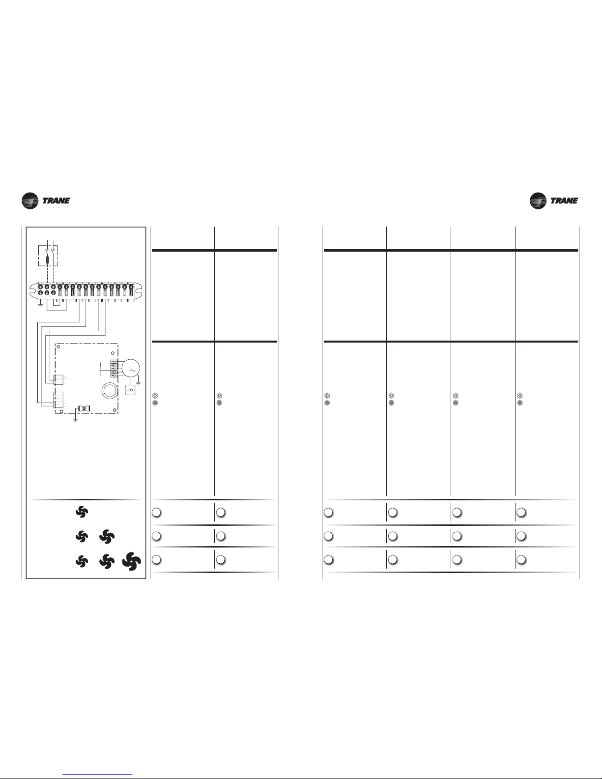
UNT-SVX26B-XX UNT-SVX26B-XX
1 Vdc =
5 Vdc =
10 Vdc =
U / V / W
0-10Vdc
ECM
DFS-/DFS+
NLPE
13
10 121411
15
798
546
FCT
PE
PE
L
N
10V
0V
DFS+
DFS-
U
V
W
T1
T1
PE
PE
230Vac
50Hz
Q1
N
L
PE
ECM BLAC board
3
M
21 21A
CT = Morsettiera
del cablaggio
FCT = Morsettiera
del FAN COIL
M = Motoventilatore
Y1/Y2 = Valvola acqua
(IMPIANTO A 2 TUBI)
Y2 = Valvola acqua CALDA
o resistenza elettrica
Y1 = Valvola acqua FREDDA
= Estate - aria fredda
= Inverno - aria calda
NTC = Sonda NTC
Q1 = Sezionatore con un polo
protetto da fusibile
(raccomandato)
T1 = Sonda aria
T3 = Sonda di minima NTC
(Optional
cod. 35169496-001)
IN1P = Cambio
stagionale esterno
EH = Resistenza elettrica
GNYE = Giallo/Verde
BN = Marrone
BU = Blu
WH = Bianco
GN = Verde
YE = Giallo
CT = Wiring
terminal board
FCT = Fan coil
terminal board
M = Fan
Y1/Y2 = Water valve
(two tube unit)
Y2 = Hot water valve
or electrical heater
Y1 = Cold water valve
= Summer - cold air
= Winter - warm air
NTC = NTC thermostat
Q1 = Circuit breakers
with one pole protected
by fuse (recommended)
T1 = Air probe
T3 = NTC Low temperature
cut-out thermostat
(Optional
code 35169496-001)
IN1P = External season
mode switch-over
EH = Electrical heater
GNYE = Yellow/Green
BN = Brown
BU = Dark blue
WH = White
GN = Green
YE = Yellow
LEGENDA LEGEND
CT = Bornier du câblage
FCT = Bornier
du ventilo-convecteur
M = Motoventilateur
Y1/Y2 = Vanne à eau
(installation à 2 tubes)
Y2 = Vanne eau chaude
ou résistance électrique
Y1 = Vanne eau froide
= Eté - air froid
= Hiver - air chaud
NTC = Sonde NTC
Q1 = Interrupteur
avec une pôle
protégé par fusible
(recommandé)
T1 = Sonde air
T3 = Sonde de température
minimum NTC
(option
code 35169496-001)
IN1P = Changement
de saison extérieur
EH = Résistance électrique
GNYE = Juane/Vert
BN = Marron
BU = Bleu foncé
WH = Blanc
GN = Vert
YE = Juane
CT = Verdrahtungs-
Klemmenbrett
FCT = Klemmenbrett
des FAN COIL
M = Motorventilator
Y1/Y2 = Wasserventil (Anlage
mit zwei Rohren)
Y2 = Warmwasserventil oder
Elektrischer Widerstand
Y1 = Kaltwasser ventil
= Sommer - kalte Luft
= Winter - warme Luft
NTC = Sonde NTC
Q1 = Hauptschalter
(empfohlen)
T1 = Luftsonde
T3 = Mindesttemperatur-
Sonde NTC (Optional
Art. Nr. 35169496-001)
IN1P = Externer
Betriebsartenwechsel
EH = Elektrischer Widerstand
GNYE = Gelb/Groen
BN = Braun
BU = Blau
WH = Weiss
GN = Groen
YE = Gelb
CT = Borna de conexión
del cableado
FCT = Borna de conexión
del ventiloconvector
M = Motoventilador
Y1/Y2 = Válvula agua (sistema de
climatización a 2 tubos)
Y2 = Válvula agua caliente
o resistencia eléctrica
Y1 = Válvula agua fría
= Verano - aire frio
= Invierno - aire caliente
NTC = Sonda NTC
Q1 = Interruptor de maniobra
seccionator de una polo
protección con fusible
(recomendado)
T1 = Sonda de aire
T3 = Sonda
de minima NTC (agua)
(Opción
cód. 35169496-001)
IN1P = Cambio externo
de temporada
EH = Resistencia eléctrica
GNYE = Amar illo/Verde
BN = Marrón
BU = Azul
WH = Blanco
GN = Verde
YE = Amarillo
CT = Klemmenbord
bekabeling
FCT = Klemmenbord
ventilatorconvector
M = Motorventilator
Y1/Y2 = Waterklep
(2-buizige installatie)
Y2 = Klep WARM water of
elektrische weerstand
Y1 = Klep KOUD water
= Zomer - koude lucht
= Winter - warme lucht
NTC = Thermostaat NTC
Q1 = Polige schakelaar met
een zekering beveiligd
(aanbevolen)
T1 = Luchtsonde
T3 = Watersonde NTC
(Optie
code 35169496-001)
IN1P = Externe
seizoenomschakeling
EH = Elektrische weerstand
GNYE = Geel/Groen
BN = Bruin
BU = Donkerblauw
WH = Wit
GN = Groen
YE = Geel
LÉGENDE LEGENDE LEYENDA LEGENDE
• Installatie met 2 leidingen
(1 klep)
• Alleen koeling
• Installatie met 2 leidingen
(1 klep)
• Thermostatische
regeling klep
• Installatie met 4 leidingen
(2 kleppen)
• Thermostatische
regeling kleppen
• Instalación con 2 tubos
(1 válvula)
• Sólo refrigeración
• Instalación con 2 tubos
(1 válvula)
• Termostatación
sobre la válvula
• Instalación con 4 tubos
(2 válvulas)
• Termostatación
sobre las válvulas
• Installation à 2 tubes
(1 vanne)
•
Refroidissement uniquement
• Installation à 2 tubes
(1 vanne)
• Thermostatation
sur le vanne
• Installation à 4 tubes
(2 vannes)
• Thermostatation
sur les vannes
• 2-Leiter-System
(1 Ventil)
• Nur Kühlung
• 2-Leiter-System
(1 Ventil)
• Temperaturregelung
der Ventil
• 4-Leiter-System
(2 Ventilen)
• Temperaturregelung
der Ventile
• 2-tube installation
(1 valve)
• Cooling only
• 2-tube installation
(1 valve)
• Thermostatic control
on the valve
• 4-tube installation
(2 valves)
• Thermostatic control
on the valves
• Impianto 2 tubi
(1 valvola)
• Solo raffrescamento
• Impianto 2 tubi
(1 valvola)
• Termostatazione
sulla valvola
• Impianto 4 tubi
(2 valvole)
• Termostatazione
sulle valvole
A
B
C
A
B
C
A
B
C
A
B
C
A
B
C
A
B
C
COMANDI
E SCHEMI ELETTRICI
ELECTRICAL
CONTROLS AND
WIRING DIAGRAMS
COMMANDES
ET SCHEMAS
ELECTRIQUES
STEUERGERÄTE
UND SCHALTPLÄNE
MANDOS
Y ESQUEMAS
ELÉCTRICOS
BEDIENINGEN EN
SCHAKELSCHEMA’S
Page 22
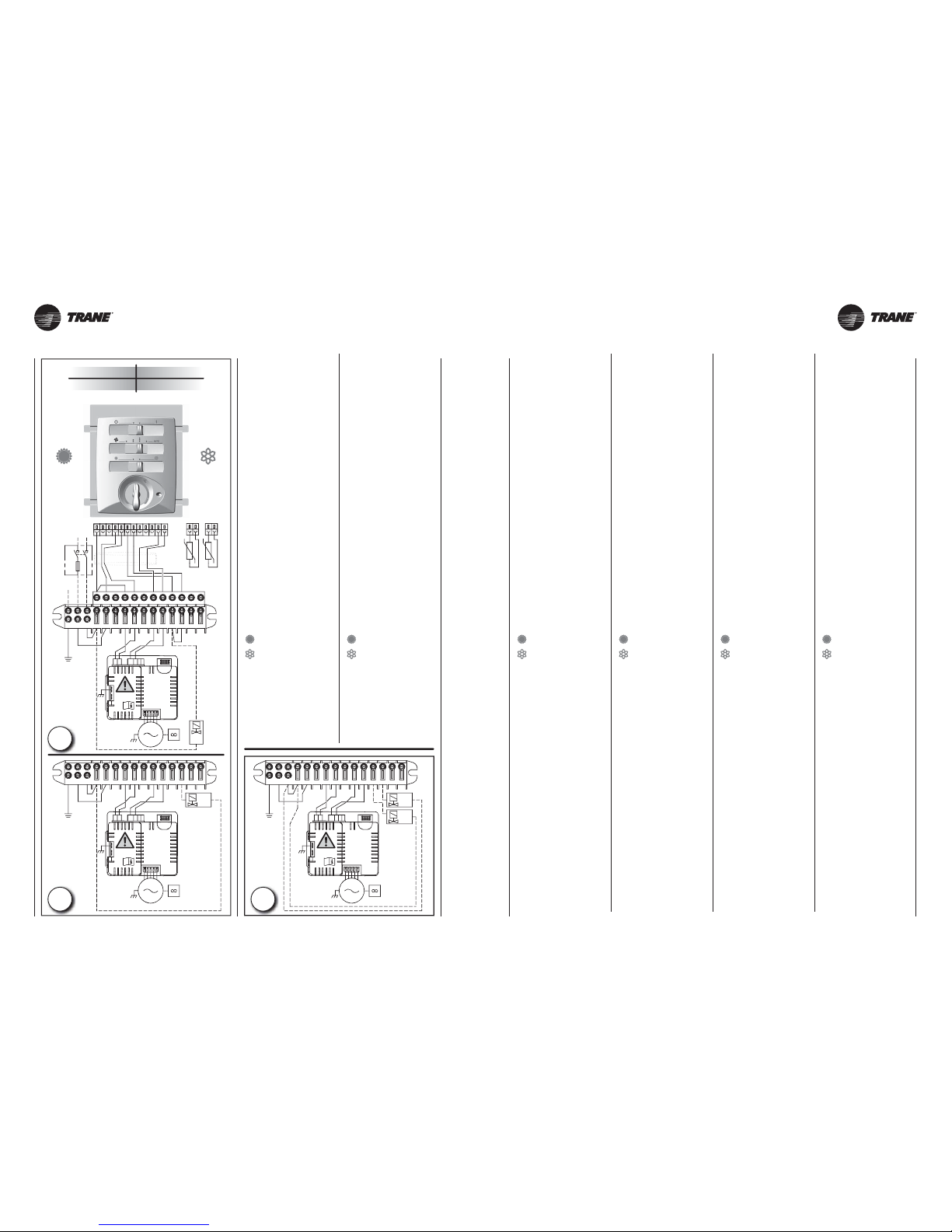
UNT-SVX26B-XX UNT-SVX26B-XX
Y1
Y2
65
7108
PE
L
14
GNYE
11
BK
13N15
12
9
BU
4
WH
RD
BU
BK
FCT
INVERTER
BLAC
BOARD
M
230V
50Hz
NL010
3
INVERTER
BLAC
BOARD
M
230V
50Hz
NL010
3
65
7108
PE
L
14
GNYE
11
BK
13N15
12
9
BU
4
WH
RD
BU
BK
FCT
Y1
INVERTER
BLAC
BOARD
M
230V
50Hz
NL010
3
NLPE
13
10 121411
15
798
546
230Vac
50Hz
7
6
32
8
4115
1
1210
9
FCT
CT
Q1
N
L
PE
T3
T1
BK
Y1
Y2
YE
2WH63
VT
RD
BK
RD
10
VT
BN
BN
BU
4
WH
9
BK
75111
12
8
YE
BU
BU
GNYE
BU
WH
BK
RD
BU
BK
22 22A
B
A
aria calda
warm air
air chaud
warme luft
aire caliente
warme lucht
aria fredda
cold air
air froid
kalte luft
aire frio
koude lucht
C
“UT-ECM”
type thermostat
Cod. 35169939-001
COMANDO ELETTRICO
CON TERMOSTATO
ELETTRONICO
Idoneo per il controllo termostatico
(ON-OFF) del ventilatore o della/e
valvola/e acqua.
Possibilità di controllo termostatico
(ON-OFF) di una valvola sull’acqua
fredda e di una valvola sull’acqua calda o resistenza elettrica.
Durante il funzionamento estivo, con
ventilatore in OFF, un timer metterà
in funzione la ventilazione per 2 minuti
ogni 15 minuti.
- Alimentare
con linea elettrica monofase
230V 50Hz rispettando
le posizioni di neutro (N)
e quella di linea (L).
Ricordarsi di allacciare la messa
a terra (PE).
- Tramite l’interruttore (0-1)
accendere il comando.
- Tramite il commutatore
scegliere la velocità.
- Tramite il deviatore
scegliere la stagione di esercizio:
= riscaldamento
= raffrescamento
- Con la manopola del termostato
settare la temperatura ambiente
desiderata.
“UT-ECM”
type thermostat
Code 35169939-001
ELECTRIC CONTROL UNIT
WITH ELECTRONIC
THERMOSTAT
For the thermostatic control (ON/OFF)
of the fan or water valve(s).
Possibility of thermostatically controlling
(ON/OFF) a water valve on the cold
water piping and a valve on the hot
water piping or an electric heater.
During summer operation with the fan
OFF, a timer activates the fan for two
minutes every 15 minutes.
- Connect to a single phase
230V 50Hz power line,
respecting the neutral (N)
and line (L) positions
and connecting the earth (PE).
- Turn on the control unit
via the O/I switch.
- Use the selector to set
the required speed.
- Use the deviator to select
the season operating mode:
= heating
= cooling
- Use the thermostat knob
to select the required room
temperature.
“UT-ECM”
type thermostat
Code 35169939-001
COMMANDE ELECTRIQUE
AVEC THERMOSTAT
ELECTRONIQUE
Adaptée au contrôle thermostatique
(ON-OFF) du ventilateur ou de la ou
des vannes à eau.
Possibilité de contrôle thermostatique
(ON-OFF) d’une vanne sur l’eau froide
et d’une vanne sur l’eau chaude ou
d’une résistance électrique.
Pendant le fonctionnement été, avec
le ventilateur OFF, un temporisateur
fera marcher la ventilation pendant 2
minutes toutes les 15 minutes.
- Alimenter avec
une ligne électrique monophasée,
230V 50Hz, en respectant
les positions de neutre (N) et
de ligne (L). Ne pas oublier
de raccorder la mise à la terre (PE).
- Allumer la commande
à l’aide de l’interrupteur (0-1).
- Choisir la vitesse
à l’aide du commutateur.
-
Choisir la saison de fonctionnement
à l’aide de l’inverseur:
= chauffage
= refroidissement
- Régler la température ambiante
souhaitée avec le bouton
du thermostat.
“UT-ECM”
type thermostat
Art. Nr. 35169939-001
ELEKTRISCHE STEUERUNG
MIT ELEKTRONISCHEM
THERMOSTAT
Geeignet für die Thermostatsteuerung
(ON-OFF) des elektrischen Ventilators
oder des Wasserventils bzw. der Wasserventile.
Möglichkeit der Thermostatsteuerung
(ON-OFF) eines Ventils am Kaltwasser
und eines Ventils am Warmwasser oder
elektrischen Heizwiderstand.
Während des Sommerbetriebs und
Ventilator auf OFF setzt eine Schaltuhr
das Gebläse alle 15 Minuten 2 Minuten
lang in Gang.
- Stromversorgung einphasig,
230V 50Hz, unter Beachtung
der Positionen von Neutralleiter (N)
und Zuleiter (L).
Nicht vergessen, den
Erdleiter (PE) anzuschließen.
- Mit dem Schalter (0-1)
die Steuerung einschalten.
- Mit dem Wählschalter
die Drehzahlstufe einstellen.
- Mit dem Wechselschalter
die Betriebsart einstellen:
= Heizung
= Kühlung
- Mit dem Drehknopf
des Thermostats die gewünschte
Raumtemperatur einstellen.
“UT-ECM”
type thermostat
Cód. 35169939-001
CONTROL ELÉCTRICO
CON TERMOSTATO
ELECTRÓNICO
Apto para el control termostático
(ON-OFF) del ventilador o de la/las
válvula/s del agua.
Posibilidad de control termostático
(ON-OFF) de una válvula en la línea del
agua fría y de una válvula en la línea
del agua caliente o resistencia eléctrica.
Durante el funcionamiento veraniego,
con ventilador en OFF, un temporizador
pone en marcha la ventilación por un
plazo de 2 minutos cada 15 minutos.
- Alimentar
con red eléctrica monofásica,
230V 50 Hz, respetando
las posiciones de neutro (N),
línea (L) y toma de tierra (PE).
- Mediante el interruptor (0-1)
encender el control.
- Mediante el conmutador
elegir la velocidad.
- Mediante el desviador
elegir la temporada de operación:
= calefacción
= refrigeración
- Con el mando del termostato
regular la temperatura ambiente
deseada.
“UT-ECM”
type thermostat
Code 35169939-001
ELEKTRISCHE BEDIENING
MET ELECTRONISCHE
THERMOSTAAT
Geschikt voor de thermostatische
regeling (ON-OFF) van de ventilator
of de waterklep(pen).
Mogelijkheid thermostatische regeling
(ON-OFF) van een klep voor het koude
water en een klep voor het warme water
of de elektrische weerstand.
In de zomermaanden, als de ventilator
op OFF staat, schakelt een timer de
ventilator elke 15 min. gedurende 2
min. in.
- Voed met een eenfasige lijn
van 230V 50Hz,
waarbij u let op de neutrale (N)
en de lijnposities (L).
- Met de schakelaar (0-1) zet
u de bediening aan, op stand 1.
- Met de omschakelaar
kiest u de gewenste snelheid.
- Met de wisselschakelaar kiest
u de gewenste seizoenswerking:
= verwarming
= afkoeling
- Met de thermostaatknop
stelt u de gewenste
omgevingstemperatuur in.
TYPE CODE
UT-ECM 35169939-001
Page 23
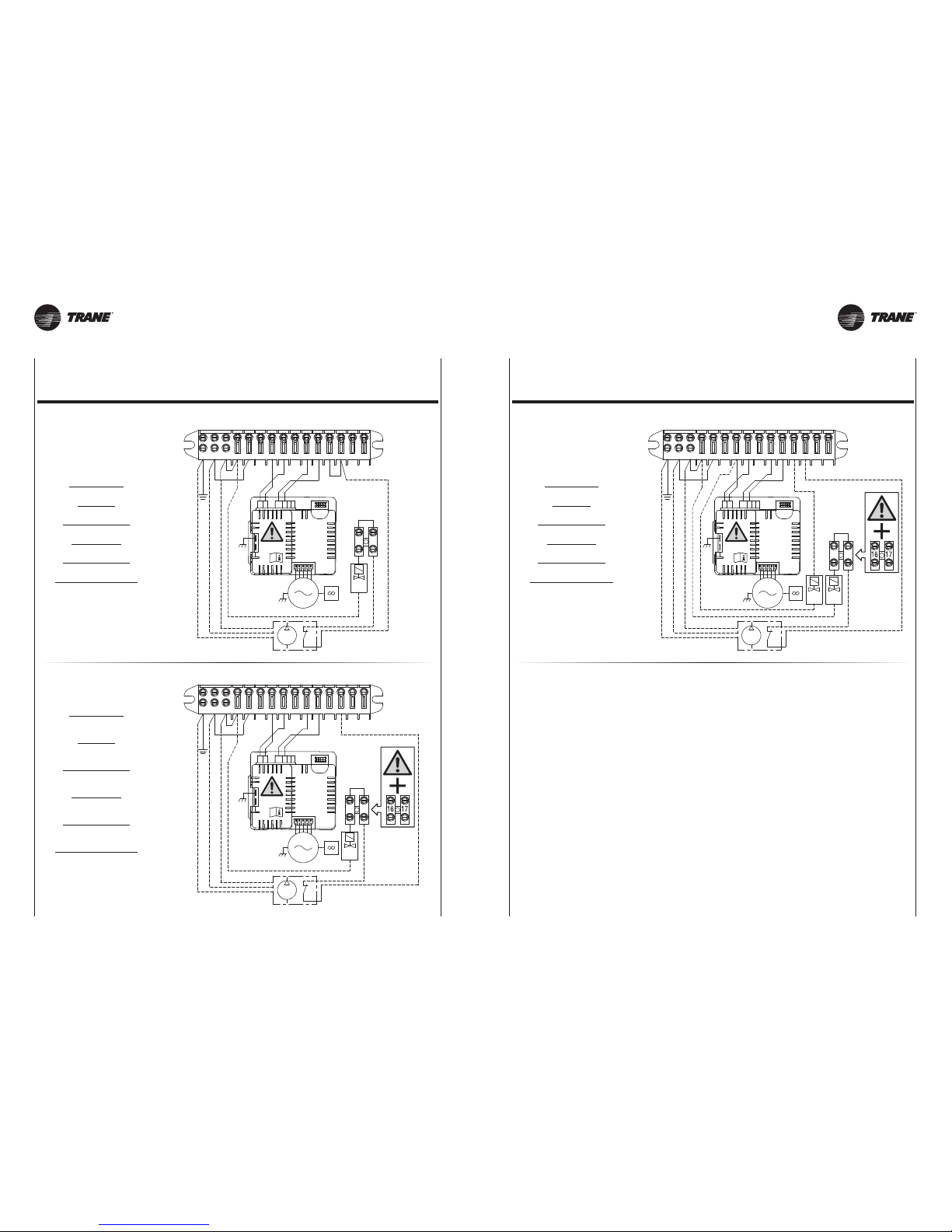
UNT-SVX26B-XX UNT-SVX26B-XX
NLPE
13
10 121411
15
798
546
FCT
BK
Y1
Y2
N
L
BK
GNYE
BU
BR
BK
B1
16
GNYE
BK
17
BU
RD
PE
BK
MP
BU
WH
65
7108
PE
L
141113N15
12
9
4
MP
BU
B1
BU
L
BR
GNYE
RD
BK
WH
GNYE
BK
N
BK
BU
PE
1716
Y1
BK
FCT
16
6Y24
17
BK
L
BK
12
WH
89
RD
MP
GNYE
13
N
B1
5
Y1
7
15
BK
11BU10
BU
BU
14
L
N
BR
PE
BK
GNYE
PE
FCT
INVERTER
BLAC
BOARD
M
230V
50Hz
NL010
3
INVERTER
BLAC
BOARD
M
230V
50Hz
NL010
3
INVERTER
BLAC
BOARD
M
230V
50Hz
NL010
3
23 23A
“UT-ECM” type thermostat
Art. Nr. / Cód. / Code 35169939-001
SCHALTPLÄNE / ESQUEMAS ELÉCTRICOS / ELEKTRISCHE SCHEMA’S
“UT-ECM” type thermostat
Cod. / Code / Code 35169939-001
SCHEMI ELETTRICI / WIRING DIAGRAMS / SCHEMAS ELECTRIQUES
Impianto a 2 tubi
con pompa
2 pipe units
with pump
Installation à 2 tubes
avec pompe
2-Leiter-Anlage
mit pumpe
Instalación a 2 tubos
con bompa
Installatie met 2 leidingen
met pomp
Impianto a 4 tubi
con pompa
4 pipe units
with pump
Installation à 4 tubes
avec pompe
4-Leiter-Anlage
mit pumpe
Instalación a 4 tubos
con bompa
Installatie met 4 leidingen
met pomp
Impianto a 2 tubi
con pompa
(solo raffrescamento)
2 pipe units
with pump
(cooilng only)
Installation à 2 tubes
avec pompe
(refroidissement uniquement)
2-Leiter-Anlage
mit pumpe
(nur Kühlung)
Instalación a 2 tubos
con bompa
(sólo refrigeración)
Installatie met 2 leidingen
met pomp
(alleen koeling)
Page 24
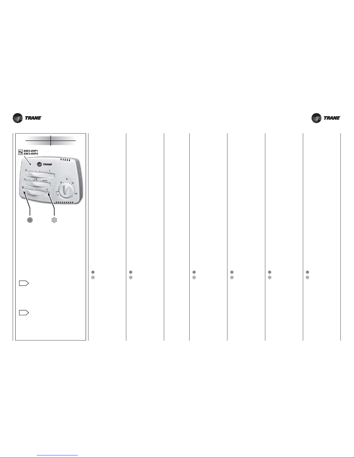
UNT-SVX26B-XX UNT-SVX26B-XX
aria calda
warm air
air chaud
warme luft
aire caliente
warme lucht
aria fredda
cold air
air froid
kalte luft
aire frio
koude lucht
24 24A
TYPE CODE
T-EC 35169886-001
“T-EC”
type thermostat
Cod. 35169886-001
COMANDO ELETTRICO
CON TERMOSTATO
ELETTRONICO
- Idoneo per controllo termostatico
(ON-OFF) del ventilatore o della/e
valvola/e acqua.
-
Per una buona sensibilità della son da, il comando con termostato de ve essere posizionato sulla parete
del locale da climatizzare, all’altez za di circa 1,5 metri e lontano da
fonti di calore e da correnti d’aria
fredda.
Togliere il coperchio del comando
e fissare la sua base sulla parete
con l’ausilio di tasselli e viti.
In relazione al tipo di impianto da
eseguire, collegare, con fili isolati
di sezione 0,75 mm
2
, i morsetti del
comando con quelli del Fan coil seguendo le indicazioni riportate sugli
schemi elettrici qui in calce, senza
dimenticare di eseguire il collega mento dei ponticelli indicati sugli
stessi.
- Alimentare
con linea elettrica monofase
230V 50Hz rispettando
le posizioni di neutro (N)
e quella di linea (L).
Ricordarsi di allacciare la messa
a terra (PE).
- Tramite l’interruttore (0-1)
accendere il comando.
- Tramite il commutatore
scegliere la velocità.
- Tramite il deviatore
scegliere la stagione di esercizio:
= riscaldamento
= raffrescamento
- Con la manopola del termostato
settare la temperatura ambiente
desiderata.
N.B.: Questo comando può ricevere
il termostato di minima elettronico
NTC.
“T-EC”
type thermostat
Code 35169886-001
ELECTRIC CONTROL UNIT
WITH ELECTRONIC
THERMOSTAT
-
For the thermostatic control (ON-OFF)
of the fan or water valve(s).
- To guarantee correct sensor
sensitivity, the control unit with
thermostat must be positioned at a
height of about 1.5 metres on a wall
of the room to be air conditioned,
away from heat sources and currents
of cold air.
Remove the cover of the control unit
and fix the base to the wall using
anchors and screws.
Depending on the type of installation,
connect the control unit terminals to
the fan coil terminals, using insulated
wires with a minimum cross section
of 0,75 mm2 and respecting the
wiring diagram below. Remember
to connect the jumpers.
- Connect to a single phase
230V 50Hz power line,
respecting the neutral (N)
and line (L) positions
and connecting the earth (PE).
- Turn on the control unit
via the O/I switch.
- Use the selector to set
the required speed.
- Use the deviator to select
the season operating mode:
= heating
= cooling
- Use the thermostat knob
to select the required room
temperature.
NB: This control can be connected to
the NTC electronic minimum thermostat.
“T-EC”
type thermostat
Code 35169886-001
COMMANDE ELECTRIQUE
AVEC THERMOSTAT
ELECTRONIQUE
-
Adaptée au contrôle thermostatique
(ON-OFF) du ventilateur ou de la
ou des vannes à eau.
- Pour une bonne sensibilité de la
sonde, la commande avec thermostat
doit être placée sur la paroi du local
à climatiser, à une hauteur d’environ
1,5 m et loin de toute source de
chaleur ou de courants d’air froid.
Retirer le couvercle de la commande
et fixer sa base sur la paroi à l’aide
de chevilles à expansion et de vis.
En fonction du type d’installation
à réaliser, raccorder, avec des
conducteurs isolés d’une section
de 0,75 mm
2
, les bornes de la
commande à celles du ventilo-con vecteur en suivant les indications
des schémas électriques ci-dessous,
sans oublier d’effectuer le raccorde-
ment des cavaliers indiqués sur ces
mêmes schémas.
- Alimenter avec
une ligne électrique monophasée,
230V 50Hz, en respectant
les positions de neutre (N) et
de ligne (L). Ne pas oublier
de raccorder la mise à la terre (PE).
- Allumer la commande
à l’aide de l’interrupteur (0-1).
- Choisir la vitesse
à l’aide du commutateur.
-
Choisir la saison de fonctionnement
à l’aide de l’inverseur:
= chauffage
= refroidissement
- Régler la température ambiante
souhaitée avec le bouton
du thermostat.
N.B.: Cette commande peut recevoir
le thermostat de température minimum
électronique NTC.
“T-EC”
type thermostat
Art. Nr. 35169886-001
ELEKTRISCHE STEUERUNG
MIT ELEKTRONISCHEM
THERMOSTAT
-
Geeignet für die Thermostatsteuerung
(ON-OFF) des elektrischen Ventilators
oder des Wasserventils bzw. der
Wasserventile.
-
Für eine gute Ansprechempfindlich-
keit der Sonde muss die Steuerung
mit Thermostat an der Wand des
Raumes, der klimatisiert werden
soll, angebracht werden, und zwar
in einer Höhe von etwa 1,5 Meter
und nicht in der Nähe von Wärme quellen und Zugluft.
Den Deckel der Steuerung abnehmen
und ihre Unterseite mit Dübeln und
Schrauben an der Wand befestigen.
Je nach Art der Anlage, die realisiert
werden soll, mit isolierten Leitern,
Mindestquerschnitt 0,75 mm
2
, die
Klemmen der Steuerung an jene
des Fan Coils anschließen; dabei
die Anleitungen der untenstehenden
elektrischen Schaltpläne befolgen und
nicht vergessen, die dort angegebenen
Überbrückungen herzustellen.
- Stromversorgung einphasig,
230V 50Hz, unter Beachtung
der Positionen von Neutralleiter (N)
und Zuleiter (L).
Nicht vergessen, den
Erdleiter (PE) anzuschließen.
- Mit dem Schalter (0-1)
die Steuerung einschalten.
- Mit dem Wählschalter
die Drehzahlstufe einstellen.
- Mit dem Wechselschalter
die Betriebsart einstellen:
= Heizung
= Kühlung
- Mit dem Drehknopf
des Thermostats die gewünschte
Raumtemperatur einstellen.
N.B.: Diese Steuerung ist für die
Aufnahme des elektronischen Mindesttemperatur-Thermostats (NTC) geeignet.
“T-EC”
type thermostat
Cód. 35169886-001
CONTROL ELÉCTRICO
CON TERMOSTATO
ELECTRÓNICO
- Apto para el control termostático
(ON-OFF) del ventilador o de la/las
válvula/s del agua.
- Para una buena sensibilidad de la
sonda es preciso colocar el control
con termostato en la pared del
cuarto a climatizar, a una altura de
aproximadamente 1,5 m y lejos de
fuentes de calor y de corrientes de
aire frío.
Quitar la tapa del control y asegu rar su base en la pared utilizando
tornillos y tacos de expansión.
Según el tipo de instalación a rea lizar conectar, con hilos aislados
que tengan una sección de 0,75 mm2,
los bornes del control con los del
fan coil, según las indicaciones pre-
sentadas en los esquemas eléctri-
cos mostrados al lado, sin olvidarse
de efectuar la conexión de los puentes indicados en dichos esquemas.
- Alimentar
con red eléctrica monofásica,
230V 50 Hz, respetando
las posiciones de neutro (N),
línea (L) y toma de tierra (PE).
- Mediante el interruptor (0-1)
encender el control.
- Mediante el conmutador
elegir la velocidad.
- Mediante el desviador
elegir la temporada de operación:
= calefacción
= refrigeración
- Con el mando del termostato
regular la temperatura ambiente
deseada.
NB: Este control puede recibir el termostato electrónico de mínima NTC.
“T-EC”
type thermostat
Code 35169886-001
ELEKTRISCHE BEDIENING
MET ELECTRONISCHE
THERMOSTAAT
- Geschikt voor de thermostatische
regeling (ON-OFF) van de ventilator
van de waterklep(pen).
- Voor een correcte werking van de
sonde, moet de bediening van de
thermostaat geplaatst worden aan
de wand van het lokaal dat moet
worden verwarmd/afgekoeld, op
een hoogte van circa 1,5 meter en
verwijderd van warmtebronnen en
koude luchtstromen.
Verwijder het lid van de bediening en
bevestig de basis aan de muur met
behulp van pluggen en schroeven.
Naargelang het uit te voeren type
installatie, gebruik geïsoleerde
draden met een minimum doorsnede
van 0,75 mm2 om de klemmen van
de bediening te verbinden met de
klemmen van de ventilatorconvector,
volgens de aanduidingen op de
elektrische schakelingen hieronder,
en let erop verbindingen te voorzien
aangeduid op de schema’s.
- Voed met een eenfasige lijn
van 230V 50Hz,
waarbij u let op de neutrale (N)
en de lijnposities (L).
- Met de schakelaar (0-1) zet
u de bediening aan, op stand 1.
- Met de omschakelaar
kiest u de gewenste snelheid.
- Met de wisselschakelaar kiest
u de gewenste seizoenswerking:
= verwarming
= afkoeling
- Met de thermostaatknop
stelt u de gewenste
omgevingstemperatuur in.
NB.: Deze bediening is geschikt voor
gebruik met elektronische uitschakelthermostaat NTC.
COMMUTAZIONE
ESTATE / INVERNO
- Possibilità di selezionare il ciclo di
funzionamento estivo o invernale
direttamente dalla pulsantiera del
comando, oppure, con un segnale
elettrico, dalla centrale termica o, ne-
gli impianti a due tubi, in modo auto matico tramite un CHANGE-OVER
in base alla impostazione selezio-
nata con il DIP interno al comando.
SUMMER / WINTER
SWITCHING
- Selecting the summer or winter
operating cycle directly from the
control keypad, via an electric signal
from the heating plant, or automatically
using a CHANGE-OVER in two-pipe
systems, based on the setting
selected by the DIP inside the control
unit.
COMMUTATION
ÉTÉ / HIVER
- Possibilité de sélectionner le cycle
de fonctionnement été ou hiver
directement à partir du tableau de
commande, ou, avec un signal
électrique, à partir de la centrale
thermique ou, dans les installations
à deux tubes, de façon automatique
par un inverseur CHANGE-OVER
selon la configuration sélectionnée
avec le DIP à l’intérieur de la
commande.
SOMMER / WINTER
OMSCHAKELING
- Möglichkeit des Einstellens von
Sommer- oder Winterbetrieb direkt
an der Schalttafel oder, über ein
elektrisches Signal, an der Heizung,
oder, bei 2-Leiter- Systemen,
automatisch mittels CHANGE-OVER,
auf Grundlage der Einstellung eines
in der Steuerung befindlichen DIP.
CONMUTACIÓN
VERANO / INVIERNO
- Posibilidad de seleccionar el ciclo
de funcionamiento verano o invier no directamente desde el teclado
del mando, o bien, con una señal
eléctrica, de la central térmica o,
en las instalaciones con dos tubos,
de forma automática mediante un
CHANGE-OVER en base a la progra mación seleccionada con el DIP
situado dentro del mando.
OMSCHAKELING
ZOMER/WINTER
- Mogelijkheid van cyclusselectie
van zomer- of winterfunctie d.m.v.
het knopbord op de bediening,
ofwel met een elektrisch signaal,
uit de thermische centrale of in de
installatie met twee leidingen, in
automatisch d.m.v. een CHANGE-
OVER volgens de ingestelde selectie
van een interne DIP.
Unità di controllo
Control unit
Unité de contrôle
Kontrolleinheit
Unidad de control
Bedieningseenheid
Unità di potenza
Power unit
Unité de puissance
Netzteil
Unidad de potencia
Vermogenseenheid
1
2
Page 25
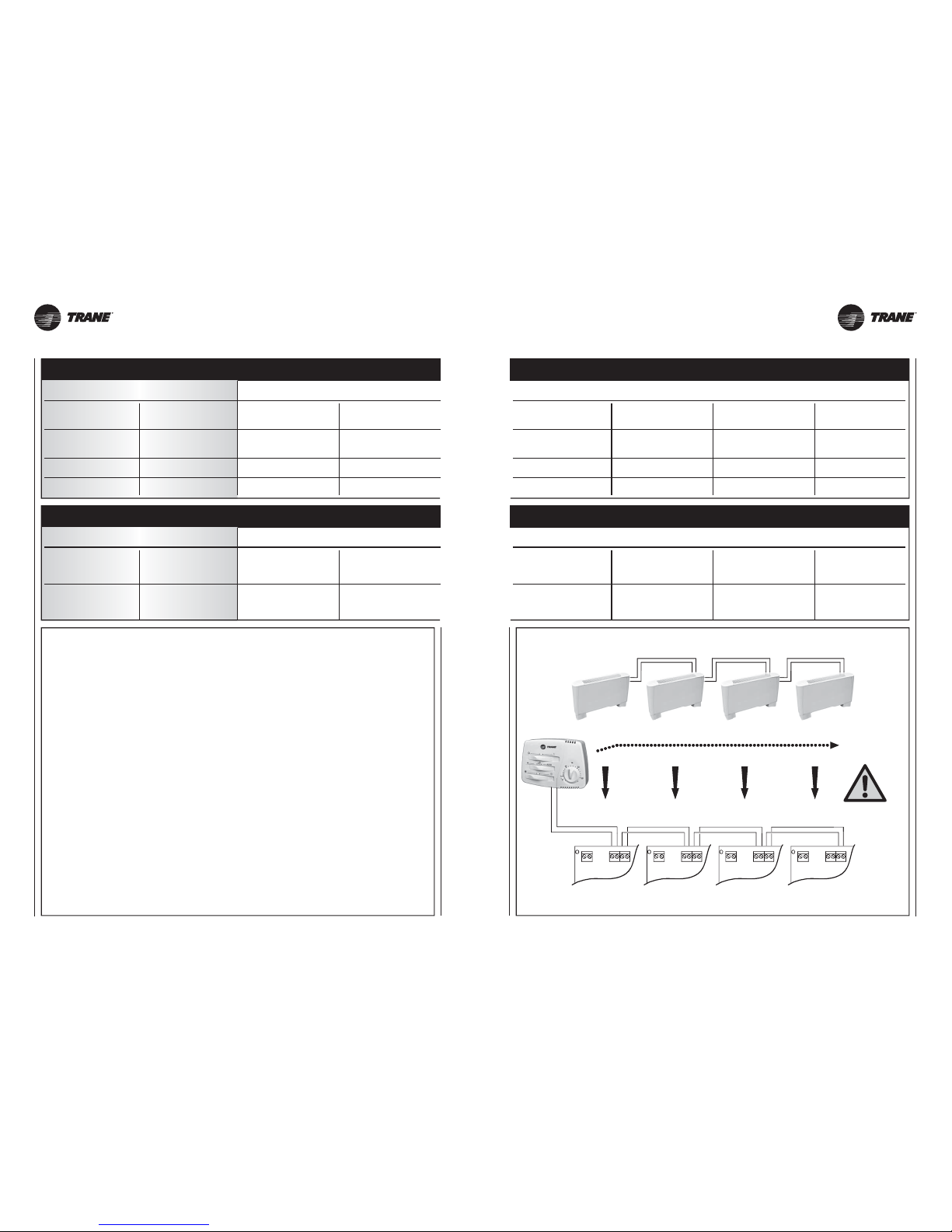
UNT-SVX26B-XX UNT-SVX26B-XX
MAX 16
tot. L = max 250m
L = max 30m
B
A
BA+0-10-
M2 M1
B
A
BA+0-10-
M2 M1
B
A
BA+0-10-
M2 M1
B
A
BA+0-10-
M2 M1
ELECTRONIC
POWER BOARD
ELECTRONIC
POWER BOARD
ELECTRONIC
POWER BOARD
ELECTRONIC
POWER BOARD
T-EC
25 25A
ON
ON
Ventilo-convecteur
au plafond positionné.
Configuration conseillée
pour installations FCAE
-
FKAE
Fan Coil
auf dem Spule positioniert.
Empfohlene Konfiguration
bei Installationen FCAE
-
FKAE
Ventiloconvector
colocado en el techo.
Configuración aconsejada
para instalaciones FCAE
-
FKAE
Fan coil
positioned on the ceiling.
Aanbevolen configuratie
voor de installaties FCAE
-
FKAE
Ventilo-convecteur
placé sur le plancher.
Configuration conseillée
pour installations FVAE
-
FKAE
Fan Coil
auf dem Boden positioniert.
Empfohlene Konfiguration
bei Installationen FVAE
-
FKAE
Ventiloconvector
colocado en el suelo.
Configuración aconsejada
para instalaciones FVAE
-
FKAE
Fan coil
positioned on the floor.
Aanbevolen configuratie
voor de installaties FVAE
-
FKAE
Commutation
été/hiver à distance
Sommer/Winter
Ferm-Umschaltung
Conmutación
verano/invierno remota
Zomer/winter-omschakeling
op afstand
Commutation
été/hiver locale
Sommer/Winterumschaltung
in der bedienung
Conmutación
Verano/Invierno local
Plaatselijke
zomer/winter-omschakeling
Thermostatation simultanée
des vannes et du ventilateur
Gleichzeitige Temperaturregelung
der Ventile und des Ventilators
Termostatación de las válvulas
y los ventiladores
al mismo tiempo
Gelijktijdige thermostatische
regeling kleppen en ventilator
Thermostatation sur les vannes
et fonctionnement continu
du ventilateur
Temperaturregelung
der Ventile und Dauerbetrieb
des Ventilators
Termostatación sobre
las válvulas y funcionamiento
contínuo del ventilador
Thermostatische regeling
kleppen en constante werking
van de ventilator
SW3-DIP
SW2-DIP
ON
ON
Ventilconvettore
posizionato a soffitto.
Configurazione consigliata
per installazioni FCAE
-
FKAE
Fan coil
positioned on the ceiling.
Configuration recommended
for FCAE
-
FKAE installations
Ventilconvettore
posizionato a pavimento.
Configurazione consigliata
per installazioni FVAE
-
FKAE
Fan coil
positioned on the floor.
Configuration recommended
for FVAE
-
FKAE installations
Commutazione
estate/inverno remota
Remote
summer/winter switching
Commutazione
estate/inverno locale
Local
summer/winter switching
1ON
DIP
1 OFF
2 OFF
2ON
Termostatazione
contemporanea delle valvole
e del ventilatore
Simultaneous
thermostatic control
on the valves and fan
Termostatazione sulle valvole
e funzionamento continuo
del ventilatore
Thermostatic control
on the valves
and continuous fan operation
SW3-DIP
1ON
DIP
SW2-DIP
1 OFF
Page 26
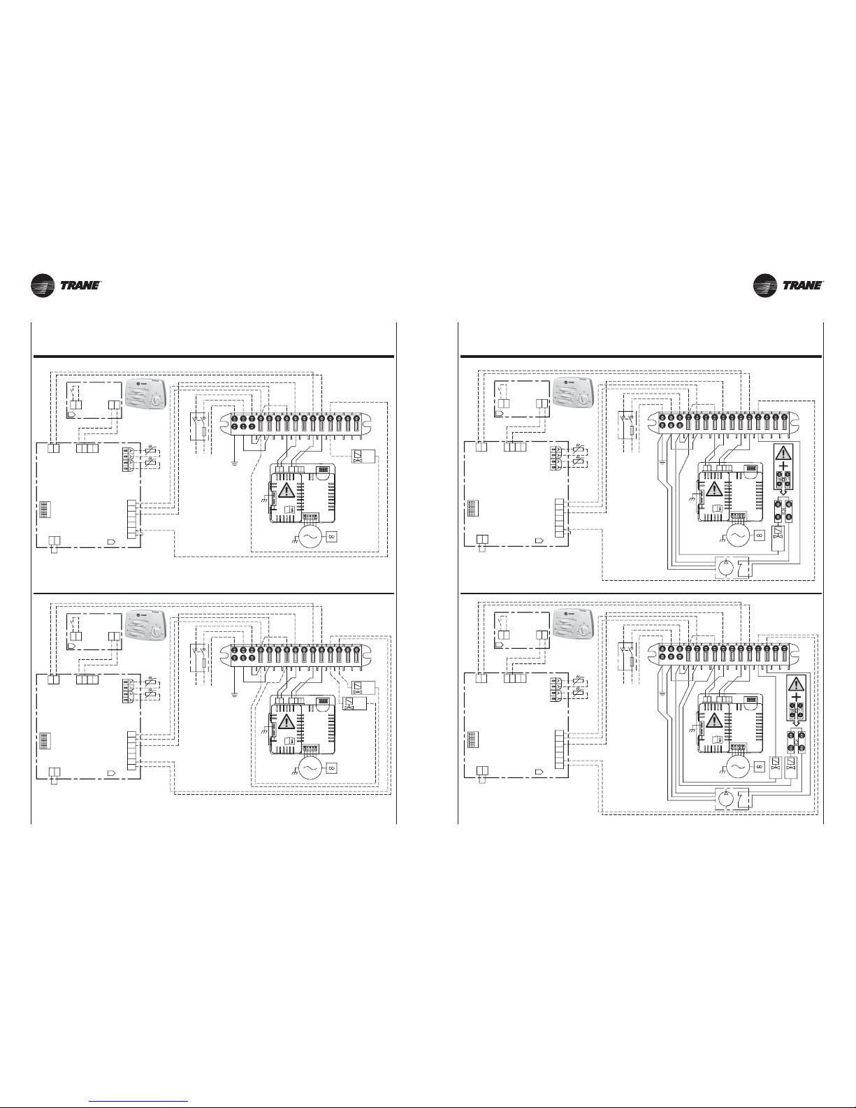
UNT-SVX26B-XX UNT-SVX26B-XX
INVERTER
BLAC
BOARD
M
230V
50Hz
NL010
3
INVERTER
BLAC
BOARD
M
230V
50Hz
NL010
3
SW2
CONFIGURATION
1
4
6
2
5
3
SW2
CONFIGURATION
1
4
6
2
5
3
T-EC
T-EC
EV1
M4
T1
FCT
11
BK
6
+0
T1
BR
IN1
GNYE
B
BK
15
BP
SEC1
UL
B
8
BU
L
Q1
L
BU
POWER
SUPPLY
230Vac 50Hz
RD
-10
EV2
N
L
M5
WH
BK
BU
N
MP
7
PE
N
M1
L
12
PE
BK
10
N
GNYE
N
T3
9
4
A
A
5
1413
PE
N
T3
1
AB
2
M2
AUX
IN1P
M1
Y1
Y2
1716
9
BK
GNYE
N
GNYE
L
N
MP
8
4
WH
10
5
14
BK
BU
BU
FCT
N
POWER
SUPPLY
230Vac 50Hz
BR
RD
7
11
L
Q1
BK
12
L
6
PE
PE
BK
1513
BU
BP
PE
-10
+0
N
EV1
N
T3
M4
SEC1
N
T3
T1
EV2
T1
UL
ABBA
M1
L
M5
IN1
2
M2
AUX
IN1P
BM1A
1
17
Y1Y2
16
T-EC
INVERTER
BLAC
BOARD
M
230V
50Hz
NL010
3
INVERTER
BLAC
BOARD
M
230V
50Hz
NL010
3
T-EC
SW2
CONFIGURATION
1
4
6
2
5
3
SW2
CONFIGURATION
1
4
6
2
5
3
EV1
M4
T1
FCT
11
BK
6
+0
T1
IN1
GNYE
B
15
SEC1
UL
B
8
BU
L
Q1
L
POWER
SUPPLY
230Vac 50Hz
RD
-10
EV2
N
L
M5
WH
BK
BU
N
7
PE
N
M1
1210
N
T3
9
4
A
A
5
1413
PE
N
T3
2
Y1
Y2
1
AB
M2
AUX
IN1P
M1
9
N
GNYE
L
8
4
WH
10
5
14
BK
BU
FCT
N
POWER
SUPPLY
230Vac 50Hz
RD
7
11
Q1
BK
12
L
6
PE
1513
BU
PE
-10
+0
N
EV1
N
T3
M4
SEC1
N
T3
T1
EV2
T1
UL
ABBA
M1
L
M5
IN1
2
M2
AUX
IN1P
BM1A
1
Y2
Y1
26 26A
VERSIONE SENZA POMPA DI EVACUAZIONE CONDENSA / VERSION WITHOUT CONDENSATE PUMP
VERSION SANS POMPE D’EVACUATION DES CONDENSATS / VERSION OHNE KONDENSATPUMPE
VERSIÓN SIN BOMBA DE EVACUACIÓN DE CONDENSADOS / VERSIE ZONDER CONDENSWATERPOMP
VERSIONE CON POMPA DI EVACUAZIONE CONDENSA / VERSION WITH CONDENSATE PUMP
VERSION AVEC POMPE D’EVACUATION DES CONDENSATS / VERSION MIT KONDENSATPUMPE
VERSIÓN CON BOMBA DE EVACUACIÓN DE CONDENSADOS / VERSIE MET CONDENSWATERPOMP
Page 27
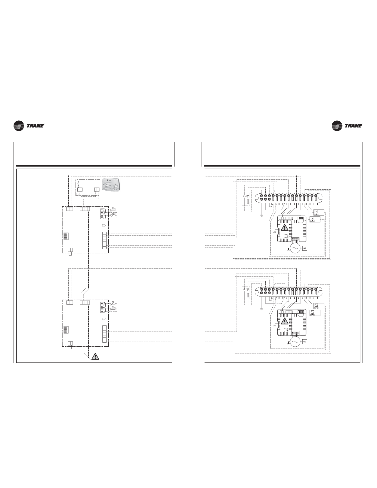
UNT-SVX26B-XX UNT-SVX26B-XX
EV1
M4
T1
+0
T1
IN1
B
SEC1
UL
B
L
-10
EV2
M5
N
N
M1
T3
A
A
N
T3
1
AB
2
M2
AUX
IN1P
M1
SW2
CONFIGURATION
1
4
6
2
5
3
INVERTER
BLAC
BOARD
M
230V
50Hz
NL010
3
INVERTER
BLAC
BOARD
M
230V
50Hz
NL010
3
SW2
CONFIGURATION
1
4
6
2
5
3
T-EC
FCT
11
BK
6
GNYE
15
8
BU
Q1
L
POWER
SUPPLY
230Vac 50Hz
RD
N
L
WH
BK
BU
7
PE
1210
N
9
45
1413
PE
Y2
Y1
9
N
GNYE
L
8
4
WH
10
5
14
BK
BU
FCT
N
POWER
SUPPLY
230Vac 50Hz
RD
7
11
Q1
BK
12
L
6
PE
1513
BU
PE
Y2
Y1
N
EV1
N
T3
N
T3
T1
EV2
T1
UL
ABBA
M1
L
M5
IN1
SEC1
2
MAX 16 UNITS
MAX TOTAL LENGHT 260 Mt
M4
+0
-10
+0
-10
L
N
UL
EV1
+0
EV2
L
N
UL
EV1
EV2
-10
+0
-10
L
N
UL
EV1
+0
EV2
L
N
UL
EV1
EV2
-10
27 27A
Steuerung meherer (max. 16) Geräte mit dem Signal einer einzigen Fernbedienung.
Controlar varios aparatos (como máximo 16) mediante la señal de un único mando a distancia.
Bediening van meerdere apparaten (max. 16) via een signaal afkomstig van een enkele afstandbediening.
SCHALTPLÄNE / ESQUEMAS ELÉCTRICOS / ELEKTRISCHE SCHEMA’S
Controllo di più apparecchi (Max 16) su segnale di un unico comando remoto.
Up to 16 units to be cotrolled by the signal from a single remote control unit.
Contrôler plusieurs appareils (16 maxi) sur signal d’une seule commande à distance.
SCHEMI ELETTRICI / WIRING DIAGRAMS / SCHEMAS ELECTRIQUES
Page 28
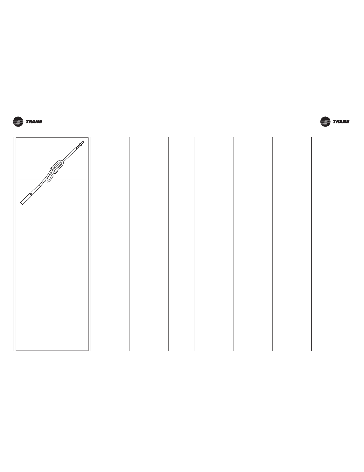
UNT-SVX26B-XX UNT-SVX26B-XX
T3 (NTC type)
28 28A
SONDA DI MINIMA
T3
Cod. 35169496-001
Da posizionare fra le alette della batteria di scambio termico.
Abbinabile ai comandi:
"UT
-
ECM" and "T-EC" type.
Per il collegamento al comando, il cavo della sonda NTC deve essere separato dai conduttori di potenza.
Durante il funzionamento invernale
arresta l’elettroventilatore quando la
temperatura dell’acqua è inferiore ai
28°C, e lo fa ripartire quando questa
raggiunge i 33°C.
T3 MINIMUM
WATER THERMOSTAT
Code 35169496-001
Position between the fins of the heat
exchanger coil.
For use with control units:
"UT
-
ECM" and "T-EC" type.
When connecting the control, the NTC
probe cable must be separated from
the power supply wires.
During winter operation stops the fan
when the water temperature drops
below 28°C and starts it up again
when the temperature reaches 33°C.
SONDE DE TEMPÉRATURE
MINIMUM T3
Code 35169496-001
Doit être placée entre les ailettes de
la batterie d’échange thermique.
Associable aux commandes:
"UT
-
ECM" and "T-EC" type.
Pour le raccordement à la commande,
le câble de la sonde NTC doit être
séparé des câbles de puissance.
Pendant le fonctionnement hiver arrête
le ventilateur quand la température de
l’eau est inférieure à 28°C et le fait
repartir quand elle atteint 33°C.
MINDESTTEMPERATUR-
FÜHLER T3
Art. Nr. 35169496-001
Diese Sonde wird zwischen den Leitlamellen der Wärmetauscher-Batterie
angebracht.
Kombinierbar mit den Steuerungen:
"UT
-
ECM" and "T-EC" type.
Für den Anschluss an die Steuerung
muss das Kabel des Fühlers NTC von
den Leistungsleitungen getrennt sein.
Der Fühler hält bei Winterbetrieb den
Ventilator an, wenn die Temperatur des
Wassers unter 28°C ist, und setzt ihn
wieder in Betrieb, wenn sie 33°C
erreicht hat.
SONDA DE MÍNIMA
T3
Cód. 35169496-001
A colocar entre las aletas de la batería
de intercambio térmico.
Combinable con los dispositivos
de accionamiento: "UT
-
ECM" and
"T
-
EC" type.
Para la conexión al mando, el cable
de la sonda NTC debe separarse de
los conductores de potencia.
Durante el funcionamiento en invierno para el electroventilador cuando
la temperatura del agua es inferior a
28°C y lo vuelve a poner en marcha
cuando esta alcanza los 33°C.
UITSCHAKEL-
THERMOSTAAT T3
Code 35169496-001
Te plaatsen tussen de ribben van de
warmtewisselaars.
Combinerend met de bedieningen:
"UT
-
ECM" and "T-EC" type.
Voor de aansluiting op de besturing,
moet de kabel van de NTC-sonde
gescheiden zijn van de stroomdraden.
Tijdens de wintercyclus schakelt hij de
elektroventilator uit als de temperatuur
van het water minder dan 28°C bedraagt,
en opnieuw inschakelt als de temperatuur
33°C bereikt.
Page 29
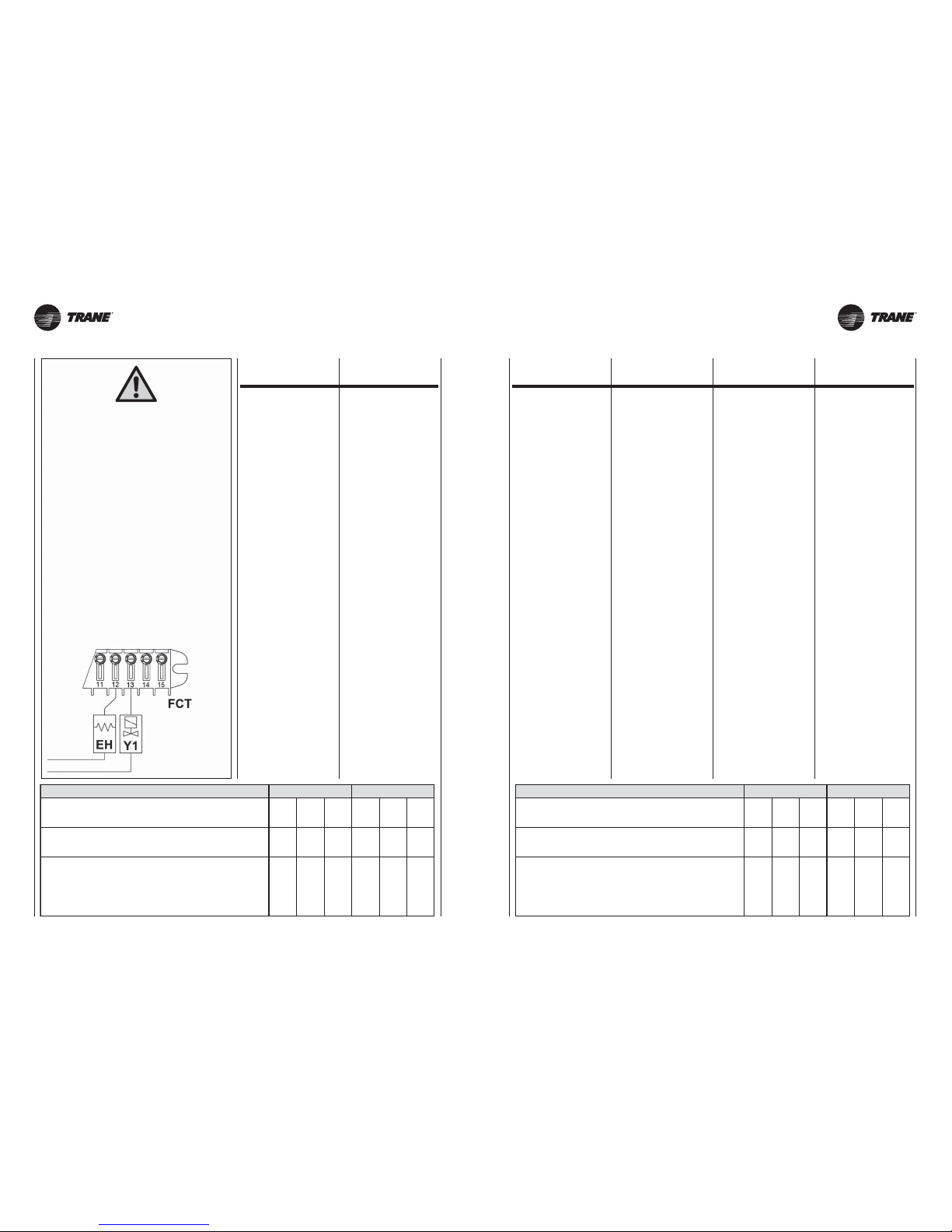
UNT-SVX26B-XX UNT-SVX26B-XX
Potenza nominale installata / Nominal installed power
Puissance nominale installée / Installierte Nennleistung
Potencia nominal instalada / Nominaal geïnstalleerd vermogen
230V
~
Corrente assorbita max. / Current input
Courant absorbé / Max. Stromaufnahme
Máxima corriente absorbida / Max. opgenomen vermogen
Fusibile consigliato (Tipo gG) per la protezione da sovraccarico
Recommended fuse (Typo gG) for overload protection
Fusible conseillé (Type gG) pour la protection de surcharge
Zum Schutz vor Überlastung empfohlene Sicherung (Typ gG)
Fusible aconsejado (Tipo gG) para la protección contra la sobrecarga
Aanbevolen zekering (Type gG) ter bescherming tegen overbelasting
400
Watt
600
Watt
1000
Watt
600
Watt
900
Watt
1500
Watt
2,0 A 2,8 A 4,5 A 2,8 A 4,0 A 6,7 A
4 A 4 A 6 A 4 A 6 A 8 A
CASING 23
Potenza nominale installata / Nominal installed power
Puissance nominale installée / Installierte Nennleistung
Potencia nominal instalada / Nominaal geïnstalleerd vermogen
230V
~
Corrente assorbita max. / Current input
Courant absorbé / Max. Stromaufnahme
Máxima corriente absorbida / Max. opgenomen vermogen
Fusibile consigliato (Tipo gG) per la protezione da sovraccarico
Recommended fuse (Typo gG) for overload protection
Fusible conseillé (Type gG) pour la protection de surcharge
Zum Schutz vor Überlastung empfohlene Sicherung (Typ gG)
Fusible aconsejado (Tipo gG) para la protección contra la sobrecarga
Aanbevolen zekering (Type gG) ter bescherming tegen overbelasting
750
Watt
1250
Watt
2000
Watt
1000
Watt
1500
Watt
2500
Watt
3,5 A 5,5 A 9,0 A 4,5 A 6,7 A 11,0 A
4 A 8 A 12 A 6 A 8 A 16 A
CASING 4 5 − 6
29 29A
BATTERIA
ELETTRICA
Per le configurazioni 2 tubi (freddo)
con resistenza elettrica, cablando il termostato a bordo,
i conduttori dedicati ad attuatore
e relay di attivazione resistenza devono essere cablati
come di seguito rappresentato.
For the configurations 2 pipes cooling
with electric heater, in case of accessories thermostat
to be mounted on the unit, the valve actuator
and electric heater relay must be wired as below.
Pour les systèmes à 2 tubes (froid)
avec la résistance électrique, de câbler le thermostat
à bord, le câblage de l'actionneur et du relais
de la résistance doit être effectuée comme suit.
Für 2-Rohr-Systeme (kalt)
mit dem elektrischen Widerstand, den Thermostat an Bord
zu verdrahten, die Verdrahtung des Relais-Antrieb
und Widerstand sollte wie folgt durchgeführt werden.
Para sistemas de 2 tubos (frío)
con la resistencia eléctrica, para conectar el termostato
a bordo, el cableado del actuador y del relé
de la resistencia se debe realizar de la siguiente manera.
Voor 2-pijps systemen (koud)
met de elektrische weerstand, om de thermostaat
aan boord van draad, bedrading van de aandrijving
en relais weerstand moet als volgt worden uitgevoerd.
ELECTRIC
RESISTANCE
BATTERIE
ÉLECTRIQUE
ELEKTROHEIZREGISTER
BATERÍA
ELÉCTRICA
ELEKTRISCHE
BATTERIJ
Le unità possono essere fornite con
resistenza elettrica (del tipo monofase
alimentazione 230Vac, costruzione
alluminio alettato) installata e cablata
direttamente in fabbrica.
La configurazione prodotto, con resistenza elettrica, prevede l’impiego di
n° 2 termostati di sicurezza atti a limitare sovratemperature interne all’apparecchio stesso.
Il termostato di primo intervento è del
tipo a riarmo automatico (pertanto
auto ripristinabile cessato il fenomeno
di guasto), mentre il termostato di secondo intervento è del tipo a riarmo
manuale (posizione dell’organo di ripristino come da immagine che segue).
In caso di intervento della protezione
a riarmo manuale occorrerà ripristinare il sistema solo dopo aver tolto
tensione ed aver accertato la causa
di guasto (intervento da effettuarsi
esclusivamente da personale preposto alla manutenzione).
Si raccomanda di non ostruire il flusso
d’aria e di controllare l’efficienza del
filtro aria con cadenza settimanale.
L’alimentazione della resistenza elettrica deve essere separata da quella
prevista per la parte moto ventilante e
provvista di propria messa a terra (PE).
Raccomandato altresì l’impiego di un
interruttore atto a garantire una disconnessione onnipolare con distanza
minima di separazione tra i contatti
pari a 3.5mm.
Per le unità con resistenza elettrica
abbinate con comandi a parete occorrerà effettuare il collegamento elettrico
come da impostazione impianto a 4
tubi dove, in luogo dell’attuatore valvola-caldo, verrà collegato il segnale
di fase per l’attivazione della resistenza elettrica. Per siffatta metodologia di
collegamento la ventilazione è continua
con termostatazione su attuatore valvola-freddo e resistenza elettrica.
Detti comandi possono gestire un solo
ventilconvettore. Per il controllo di più
ventilconvettori, con unico comando,
è necessario che ogni apparecchio sia
corredato di un selettore di velocità REL
che, su segnale del comando remoto,
azionerà il proprio apparecchio.
The units can be supplied with an
electric heating element (230Vac singlephase, finned aluminium structure)
fitted and wired directly in the factory.
The configuration of the product with
the electric heating element is intended
to be used with 2 safety thermostats
which limit the internal over temperature
of the unit.
The first intervention thermostat has
automatic rearming (and therefore is
reset automatically as soon as the fault
has ended), whereas the second
intervention thermostat has manual
rearming (the position of the reset
device is as shown in the figure).
In the event the manual rearm protective
device intervenes, the system will need
to be restored only after having cut
power and found out the cause of the fault
(intervention reserved for maintenance
operators alone).
It is recommended not to obstruct the
air flow and to check the efficiency of
the air filter once a week.
The electric heating element must be
powered separately from the fan motor
and must be provided with its own
earthing (PE).
It is also recommended to use a switch
providing an omnipolar disconnection
with a minimum separation distance
between the contacts of 3.5mm.
For the units with heating elements
coupled with wall-mounted controls,
an electrical connection will need to
be performed as for the 4-pipe system
where, in place of the valve actuatorheat, the phase signal will be connected
for activation of the electric heating
element. In this type of connection,
ventilation is continuous with thermostat
control on the valve actuator-cold and
electric heating element.
These controls can manage only one
fan coil. In order to manage more than
one fan coil with one sole control, each
appliance must be equipped with a REL
speed selector which, upon receiving
a remote control signal, activates its
own appliance.
Les unités peuvent être fournies avec la
résistance électrique (du type monophasé
alimentation 230Vac, construction
aluminium avec éléments à ailettes)
installée et câblée directement en usine.
La configuration du produit, avec
résistance électrique, prévoit l’utilisation
de n°2 thermostats de sécurité, aptes
à limiter les surchauffes internes à
l’appareil lui-même.
Le thermostat de première intervention est
à réarmement automatique (donc à auto
rétablissement une fois que la panne est
terminée), alors que le thermostat de seconde
intervention est du type a réarmement
manuel (position de l’organe de rétablissement comme sur les images en annexe).
En cas d’intervention de la protection à
réarmement manuel, il faudra rétablir le
système seulement après avoir enlevé la
tension et avoir vérifié la cause de la panne
(intervention qui doit être exclusivement
effectuée par un personnel préposé à la
maintenance).
On recommande de ne pas obstruer
le flux d’air et de contrôler l’efficacité
du filtre à air chaque semaine.
L’alimentation de la résistance électrique
doit être séparée de celle prévue pour
la partie moto-ventilante et pourvue
de sa propre mise à la terre (PE).
De plus, l’utilisation d’un interrupteur
apte à garantir une déconnexion omni-
polaire est recommandé avec une
distance minimum de séparation entre
les contacts égale à 3.5mm.
Pour les unités avec résistance électrique
associées avec des commandes murales,
il faudra effectuer un branchement électrique
comme la configuration d’une installation
à 4 tuyaux où, à la place de l’actionneur
soupape-chaud, sera relié le signal de
phase pour l’activation de la résistance
électrique. Pour cette méthode de branchement, la ventilation est continue avec une
thermostation sur actionneur soupape-froid
et résistance électrique.
Ces commandes peuvent gérer un unique
ventilo-convecteur. Pour le contrôle de
plusieurs ventilo-convecteurs avec une seule
commande, il est nécessaire que chaque
appareil soit équipé d’un sélecteur de vitesse
REL qui, sur un signal de commande à
distance, actionnera directement l’appareil.
Die Einheiten können mit einem elektrischen
Widerstand geliefert werden (Typ einphasige Stromversorgung 230Vac,
Bauweise aus geripptem Aluminium),
werkseitig installiert und verkabelt.
Die Produktkonfiguration mit elektrischem,
Widerstand sieht den Einsatz von 2
Sicherheitsthermostaten vor, die eine
Übererwärmung im Geräteinneren selbst
begrenzen.
Das Thermostat für den ersten Eingriff ist
mit automatischem Reset (und wird daher
nach der Beseitigung der Störungsursache
automatisch rückgestellt); das zweite
Thermostat dagegen ist mit manuellem
Reset (Position der Reset-Bedienung
siehe beiliegende Abbildung).
Im Falle eines Eingriffs der Schutzvorrichtung
mit manuellem Reset, kann das System nur
rückgestellt werden, nachdem die Spannung
abgetrennt wurde und die Ursache der
Störung beseitigt wurde (dieser Eingriff
darf ausschließlich vom zuständigen
Wartungspersonal ausgeführt werden).
Wir empfehlen, den Luftstrom nicht zu
hemmen und die Leistungsfähigkeit
des Filters wöchentlich zu überprüfen.
Die Versorgung des elektrischen Widerstands muss getrennt von der für die
Lüftungsaggregate erfolgen und eine
eigene Erdungsleitung besitzen (PE).
Außerdem muss ein Schalter vorgesehen
werden, um ein allpoliges Abtrennen
zu garantieren, und zwar mit einem
Trennmindestabstand zwischen den
Kontakten gleich 3.5mm.
Bei den Einheiten mit elektrischem
Widerstand und Wandsteuerungen muss
der elektrische Anschluss wie bei Anlagen
mit vier Leitern erfolgen, wo, an Stelle des
Stellglieds - Warmventils das Phasensignal für die Aktivierung des elektrischen
Widerstands angeschlossen wird. Diese
Anschlussart hat eine Dauerlüftung; wo
die Temperatur an Stellglied Kaltventil
und elektrischem Widerstand konstant
gehalten wird.
Diese Steuerungen können nur einen
Gebläsekonvektor steuern. Für die Kontrolle
mit mehreren Gebläsekonvektoren, mit einer
einzigen Steuerung, ist es nötig, dass jedes
Gerät mit Geschwindigkeitswahlschalter
REL ausgerüstet ist; auf ein Signal der
Fernsteuerung hin aktiviert er das Gerät.
Las unidades pueden ser suministradas
con resistencia eléctrica (del tipo monofásica con alimentación de 230 V AC,
fabricada en aluminio acanalado) instalada y cableada directamente de fábrica.
La configuración del producto, con
resistencia eléctrica, prevé el uso de
2 termostatos de seguridad aptos para
limitar las sobretemperaturas internas
del aparato.
El termostato de primera intervención es
de tipo de rearme automático (por lo tanto,
se autoresetea una vez que ha cesado
la avería), mientras que el termostato de
segunda intervención es de tipo de rearme
manual (posición de la pieza de reseteo
como se muestra en la imagen adjunta).
En caso de intervención de la protección
de reseteo manual es necesario restablecer
el sistema sólo después de haber desconectado la tensión y de haber constatado
la causa de la avería (la operación debe
ser realizada exclusivamente por el
personal encargado del mantenimiento).
Se recomienda no obstruir el flujo de
aire y controlar la eficacia del filtro de
aire con una frecuencia semanal.
La alimentación de la resistencia eléctrica debe estar separada de la prevista
para la parte motoventilante y debe
contar con su propia puesta a tierra (PE).
También se recomienda el empleo de
un interruptor apto para garantizar una
desconexión omnipolar con distancia
mínima de separación entre los contactos equivalente a 3,5 mm.
Para las unidades con resistencia eléctrica combinadas con mandos de pared
será necesario realizar la conexión eléctrica como en la configuración de una
instalación con 4 tubos donde, en lugar de
la servoválvula-calor, se conectará la señal
de fase para la activación de la resistencia
eléctrica. En el caso de esta metodología
de conexión, la ventilación es continua
con termostatación en la servoválvula-frío
y resistencia eléctrica.
Dichos mandos pueden controlar un
solo ventiloconvector. Para el control
de más ventiloconvectores, con un único
mando, es necesario que cada aparato
cuente con un selector de velocidad
REL que, a la señal de mando remoto,
accionará el aparato.
De eenheden kunnen met een elektrische
weerstand (van het type monofase met
voeding 230Vac, constructie gevinde
aluminium) geleverd worden, geïnstalleerd
en direct bekabeld door de fabriek.
De configuratie van het product met
elektrische weerstand voorziet het gebruik
van 2 beveiligingsthermostaten bedoeld
om te hoge temperaturen binnenin het
toestel te beperken.
De thermostaat voor eerste interventie is
van het type met automatische ontgrendeling
(dus zelfherstartend als het fenomeen
van het defect verdwijnt), terwijl de
thermostaat voor tweede interventie
van het type met manuele ontgrendeling
is (plaats van het herstartmechanisme
zoals in de afbeelding in bijlage).
Bij interventie door de beveiliging met
manuele ontgrendeling mag men het
systeem enkel herstarten nadat de
spanning werd weggenomen en de
oorzaak van het defect werd opgespoord
(interventie uitsluitend uit te voeren door
personeel belast met het onderhoud).
Het is aanbevolen om de luchtstroom
niet af te dichten en wekelijks de efficiëntie
van de luchtfilter te controleren.
De voeding van de elektrische weerstand
moet gescheiden zijn van de voeding
voorzien voor het ventilerende gedeelte
en uitgerust met een eigen aarding (PE).
Bovendien is het gebruik aanbevolen
van een schakelaar die een onnipolaire
verbreking kan garanderen, met minimum
3.5mm scheidingsafstand tussen de
contacten.
Voor de eenheden met elektrische weerstand
gekoppeld aan commando’s aan de wand
die zijn, moet men de elektrische aansluiting
uitvoeren zoals bij de opstelling van de
installatie met 4 pijpen waarbij, in plaats van
de aandrijving klep-warm, het fasesignaal
voor de activering van de elektrische weerstand
wordt aangesloten. Bij een dergelijke
aansluitingsmethode is de ventilatie continu
met thermostaatinstelling op de aandrijving
klep-koud en elektrische weerstand.
Voornoemde commando’s kunnen één enkele
ventilator-convector besturen. Voor de
besturing van meerdere ventilator-convectoren
met één enkel commando moet elk toestel
uitgerust zijn met een keuzeschakelaar
voor de snelheid REL die bij signaal van het
commando op afstand het eigen toestel aanzet.
Page 30
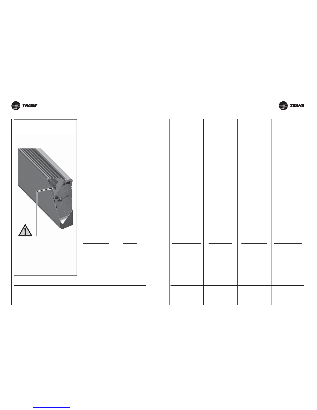
UNT-SVX26B-XX UNT-SVX26B-XX30 30A
Q1 = Interruttore generale
Q2 = Relè di potenza
TS1 = Termostato
a riarmo automatico
TS2 = Termostato
a riarmo manuale
R1 = Resistenza
Q1 = Main switch
Q2 = Power relay
TS1 = Thermostat
with automatic reset
TS2 = Thermostat
with manual reset
R1 = Resistance
LEGENDA LEGEND
Q1 = Interrupteur général
Q2 = Relais de puissance
TS1 = Thermostat
à réarmement automatique
TS2 = Thermostat
à réarmement manuel
R1 = Résistance
Q1 = Hauptschalter
Q2 = Leistungsrelais
TS1 = Thermostat
mit automatischem Reset
TS2 = Thermostat
mit manuellem Reset
R1 = Heizregister
Q1 = Interruptor general
Q2 = Relé de potencia
TS1 = Termostato
de rearme automático
TS2 = Termostato
de rearme manual
R1 = Resistencia
Q1 = Hoofdschakelaar
Q2 = Relais van vermogen
TS1 = Thermostaat
met automatische reset
TS2 = Thermostaat
met handmatige reset
R1 = Weerstand
LÉGENDE LEGENDE LEYENDA LEGENDE
POSIZIONE DEL PULSANTE DI RIARMO
DEL TERMOSTATO DI SICUREZZA
POSITION
OF THE SAFETY THERMOSTAT RESET BUTTON
POSITION DE LA TOUCHE DE RÉARMEMENT
DU THERMOSTAT DE SÉCURITÉ
POSITION DER RESETTASTE
DES SICHERHEITSTHERMOSTATS
POSICIÓN DEL PULSADOR DE REARME
DEL TERMOSTATO DE SEGURIDAD
POSITIE VAN DE RESETKNOP
VAN DE VEILIGHEIDSTHERMOSTAAT
Avvertenze
In fase di prima installazione, prima
di attivare le resistenze elettriche verificare che il ventilatore del cassette
funzioni correttamente a tutte e tre le
velocità previste.
Si raccomanda di non ostruire il flusso d’aria e di controllare l’efficienza
del filtro aria settimanalmente.
Nelle versioni con resistenza non è
possibile utilizzare la sonda T3 per il
rilevamento della temperatura acqua
in batteria.
Protezione
contro le sovra-temperature
Termostati di sicurezza
L'apparecchio è dotato di n° 2 termostati di sicurezza entrambi posizionati
direttamente sulla resistenza elettrica:
- un termostato a riarmo
automatico (I° intervento);
- un termostato a riarmo
manuale (II° intervento). Il riarmo
del termostato viene effettuato
premendo il tasto evidenziato
in figura.
Nel caso di intervento del termostato
di sicurezza individuare sempre le
cause che ne hanno provocato l’intervento prima di rialimentare le resistenze elettriche dell’apparecchio.
Nel caso non si riesca ad individuare
la causa dell’intervento della protezione, contattare il personale tecnico
qualificato.
Limite di impiego
Fan Coil con batteria elettrica
Max. temperatura ambiente per
Fan Coil con batteria elettrica in
riscaldamento: 25°C
Warnings
When first installing the appliance,
before starting the electric heaters,
check that the fan on the cassette
unit is working correctly at all three
speeds envisaged.
The air flow should not be obstructed
and the efficiency of the air filter should
be controlled weekly.
The T3 probe can not be used on the
versions with electric heater to measure
the heater water temperature.
Protecting
against excess temperature
Safety thermostats
The appliance is equipped with 2
safety thermostats both located directly
on the electrical resistance:
- a self resetting
safety thermostat (first cut out
operation);
- a manual resetting
safety thermostat (second cut out
operation). The thermostat
is reset by pressing the button
highlighted in the figure.
If the safety thermostat trips, always
identify the causes before restarting
the electric heaters on the appliance.
If the problem that caused the
activation of the thermostat cannot
be found, contact qualified technical
personnel.
Fan Coil unit operating limits
with electric coil
Max. ambient temperature for
Fan Coil
unit with electric coil in heating mode:
25°C
Attention
Lors de la première installation, avant
d’allumer les résistances électriques,
vérifier que le ventilateur du ventiloconvecteur cassette fonctionne correctement aux trois vitesses prévues.
Il est recommandé de ne pas obstruer
le flux d’air et de contrôler l’efficacité
du filtre à air toutes les semaines.
Dans les versions à résistance il n’est
pas possible d’utiliser la sonde T3 pour
détecter la température de l'eau dans
la batterie.
Protection
contre les surtempératures
Thermostat de sécurité
L'appareil est équipé de 2 thermostats
de sécurité à la fois situés directement
sur la résistance électrique:
- un thermostat à réarmement
automatique (première découper
fonctionnement);
- un thermostat à réarmement
manuel (deuxième découper
opération). Pour réarmer
le thermostat appuyer sur
la touche indiquée dans la figure.
En cas de déclenchement du thermostat de sécurité en rechercher
la cause avant d’alimenter de nouveau les résistances électriques de
l’appareil.
S’il n’est pas possible de trouver la
cause qui a déclenché la protection,
contacter un technicien qualifié.
Limite d’emploi
Fan Coil avec batterie électrique
Température ambiante maxi pour
Fan Coil avec batterie électrique en
chauffage: 25°C
Hinweise
Bevor während der Erstinstallation die
Heizregister aktiviert werden, muss
sichergestellt werden, dass der Ventilator
des Kassetten-Klimakonvektors bei allen drei
vorgesehenen Drehzahlen korrekt funktioniert.
Den Luftstrom nicht behindern und
wöchentlich die Effizienz des Luftfilters
kontrollieren.
Bei den Versionen mit Heizregister kann
der Fühler T3 nicht verwendet warden
zum Erfassen der Temperatur des
Wassers in der Batterie.
Sicherungssystem gegen
Überhitzung
Sicherheitsthermostate
Das Gerät ist mit 2 SicherheitsThermostate sowohl direkt auf den
elektrischen Widerstand befindet
ausgestattet:
- Ein Thermostat
mit automatischem Reset
(first out Arbeitsgang geschnitten);
- Ein Thermostat
mit manuellem Reset
(zweiter Ausschnitt Betrieb).
Der Reset des Thermostats erfolgt
durch Drücken der auf
der Abbildung gezeigten Taste.
Wenn der Sicherheitsthermostatausgelöst wurde, muss immer die
Ursache herausgefunden werden, bevor
die Heizwiderstände des Gerätserneut
unter Spannung gesetzt werden.
Falls die Ursache für das Ansprechen
der Sicherheitseinrichtung nicht ausfindig
gemacht werden kann, wenden Sie sich
bitte an qualifiziertes technisches Personal.
Einsatzgrenze
Fan Coil mit Elektroregister
Max. Raumtemperatur für Fan Coil
mit Elektroheizregister: 25°C
Advertencias
En la primera instalación, antes de
activar las resistencia eléctricas verificar que el ventilador del cassette
funcione correctamente a todas las
3 velocidades previstas.
Se recomienda no obstruir el flujo de
aire y controlar cada semana la eficiencia del filtro del aire.
En las versiones con resistencia no
se puede usar la sonda T3 para la
detección de la temperatura del agua
en la batería.
Protección
contra el sobrecalentamiento
Termostatos de seguridad
La unidad está equipada con 2 termostatos de seguridad tanto situados
directamente en la resistencia eléctrica:
- un termostato
de rearme automático
(primer recorte de operación);
- un termostato
de rearme manual (segundo
corte a cabo la operación).
El rearme del termostato
se realiza pulsando la tecla
que puede verse en la figura.
En caso de intervención del termostato de seguridad detectar siempre
la causa que ha provocado dicha intervenciòn antes de realimentar las resistencias eléctricas del aparato.
En caso de que no se consiga localizar la causa de la intervención de la
protección, contacte con el personal
técnico cualificado.
Límite de uso
Fan Coil con batería eléctrica
Temperatura ambiente máxima para
Fan Coil con batería eléctrica en
calefacción: 25°C
Voorschriften
Bij de eerste installatie en alvorens
de elektrische weerstanden in te
schakelen, controleer of de ventilator
van Casette correct werkt op de drie
voorziene snelheden.
Wij raden u aan niet de luchtstroom
blokkeren en om de efficiëntie van de
luchtfilter wekelijks controleren.
In de versies met weerstand is het
niet mogelijk gebruik te maken van de
uitschakelthemostaat T3 aan het
water temperatuur van de batterij te
detecteren.
Beveiligingssysteem tegen
oververhitting
Veiligheidsthermostaten
Het apparaat is voorzien van 2 veiligheidsthermostaten beide gelegen direct aan
de elektrische weerstand:
- een thermostaat
met automatische reset
(eerste uitgesneden operatie);
- een thermostat
met handmatige reset
(tweede cut out operatie).
De thermostaat wordt gereset
door op de toets afgebeeld
in de figuur te drukken.
Ingeval de veiligheidsthemostaat
in werking treedt, wordt altijd naarde
oorzaak hiervan gepeild alvorensde
elektrische weerstanden van het
apparaat terug te voeden.
Indien niet de oorzaak van de ingreep
van de beveiliging gevonden kan
worden, neem dan contact op met
vakkundig technisch personeel.
Gebruikslimiet
Fan Coil met elektrische batterij
Max. omgevingstemperatuur voor
Fan Coil met elektrische batterij
tijdens verwarming: 25°C
Page 31
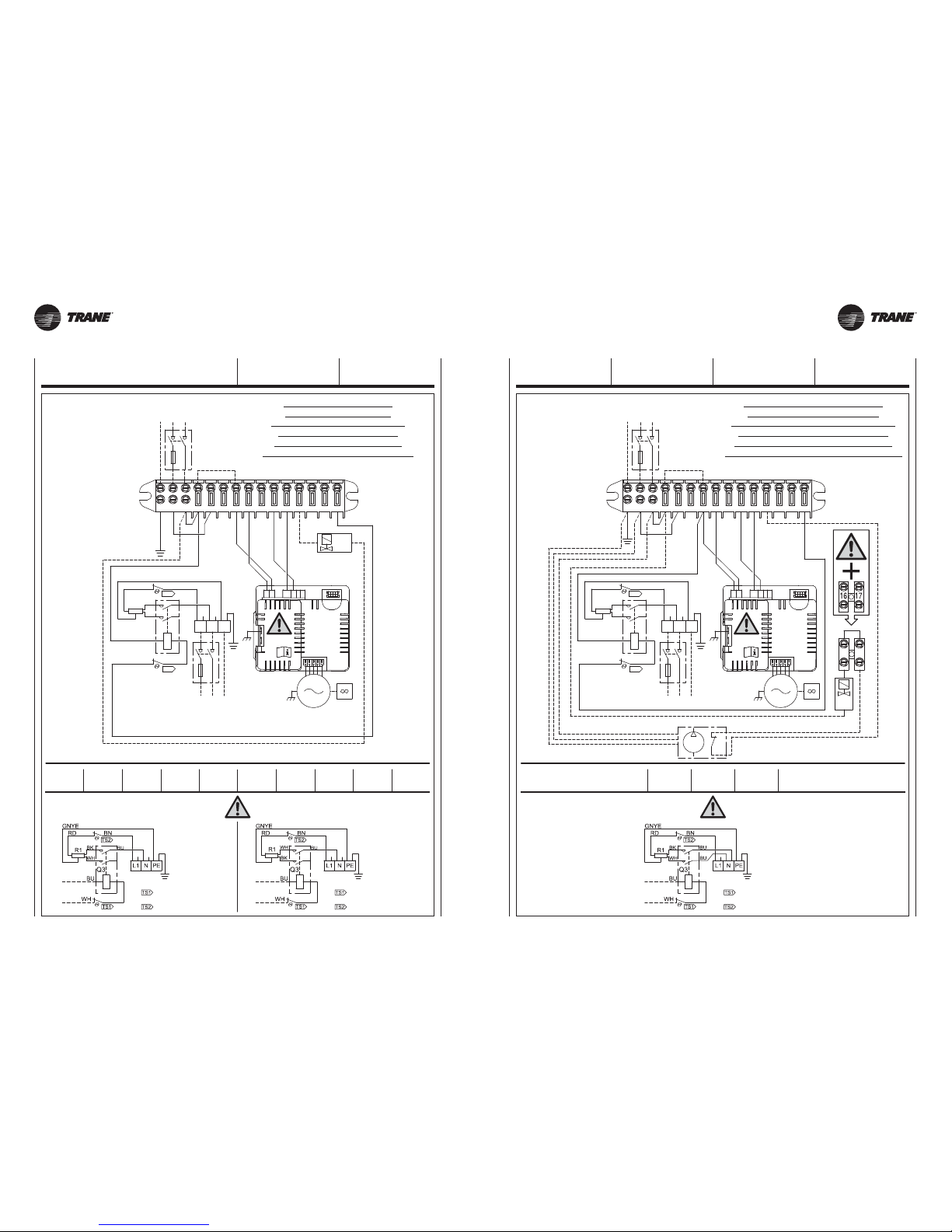
UNT-SVX26B-XX UNT-SVX26B-XX
DETTAGLIO COLLEGAMENTO ELETTRICO
ELECTRIC HEATER WIRING DETAIL
DÉTAILS RACCORDEMENT ÉLECTRIQUE
DETAIL DER ELEKTRISCHEN VERBINDUNG
DETALLES CONEXIÓN ELÉCTRICA
ELEKTRISCHE AANSLUITING DETAIL
Casing 2
1000 Watt
Casing 3
1500 Watt
Casing 4
2000 Watt
Casing 5
2500 Watt
Casing 6
2500 Watt
Thermal cut Off = 235°C
Automatic Reset
Thermal cut Off = 190°C
Manual Reset
B1
N
PE
MP
L
BK
BK
4
9
12
15
N
13
BK
11
14
L
PE
8107
56
BU
Q3
POWER
SUPPLY
230Vac 50Hz
L1NPE
Q2
L1NPE
R1
TS1
TS2
RD
GNYE
BK
WH
BU
BU
BN
Q1
FCT
230V
50 Hz
PE
L
N
BU
BR
BU
GNYE
Y1
1716
VT
BU
BK
RD
WH
INVERTER
BLAC
BOARD
M
230V
50Hz
NL010
3
DETTAGLIO COLLEGAMENTO ELETTRICO
ELECTRIC HEATER WIRING DETAIL
DÉTAILS RACCORDEMENT ÉLECTRIQUE
DETAIL DER ELEKTRISCHEN VERBINDUNG
DETALLES CONEXIÓN ELÉCTRICA
ELEKTRISCHE AANSLUITING DETAIL
Casing 2
400 Watt
Casing 3
600 Watt
Casing 4
750 Watt
Casing 5
1000 Watt
Casing 6
1000 Watt
Casing 2
600 Watt
Casing 3
900 Watt
Casing 4
1250 Watt
Casing 5
1500 Watt
Casing 6
1500 Watt
Thermal cut Off = 190°C (Mod. 2−4)
Thermal cut Off = 160°C (Mod. 3−5−6)
Automatic Reset
Thermal cut Off = 235°C
Manual Reset
Thermal cut Off = 135°C
Automatic Reset
Thermal cut Off = 235°C
Manual Reset
N
L
PE
230V
50 Hz
FCT
Q1
BN
BU
BU
WH
BK
GNYE
RD
TS2
TS1
R1
PE
N
L1
Q2
PE
N
L1
POWER
SUPPLY
230Vac 50Hz
Q3
BU
65
7108
PE
L
14
GNYE
11
BK
13N15
12
9
4
Y1
BU
WH
BK
RD
VT
INVERTER
BLAC
BOARD
M
230V
50Hz
NL010
3
31 31A
SCHEMI
ELETTRICI
WIRING
DIAGRAMS
SCHEMAS
ELECTRIQUES SCHALTPLÄNE
ESQUEMAS
ELÉCTRICOS SCHAKELSCHEMA’S
Impianto 2 tubi + Batteria elettrica
2 pipe units + Electric resistance
Installation à 2 tubes + Batterie électrique
2-Leiter-Anlage + Electro-heizregister
Instalación a 2 tubos + Bateria electrica
Installatie met 2 leidingen + Elektrische batterij
Impianto 2 tubi + Batteria elettrica + pompa
2 pipe units + Electric resistance + pump
Installation à 2 tubes + Batterie électrique + pompe
2-Leiter-Anlage + Electro-heizregister + pumpe
Instalación a 2 tubos + Bateria electrica + bomba
Installatie met 2 leidingen + Elektrische batterij + pomp
Page 32
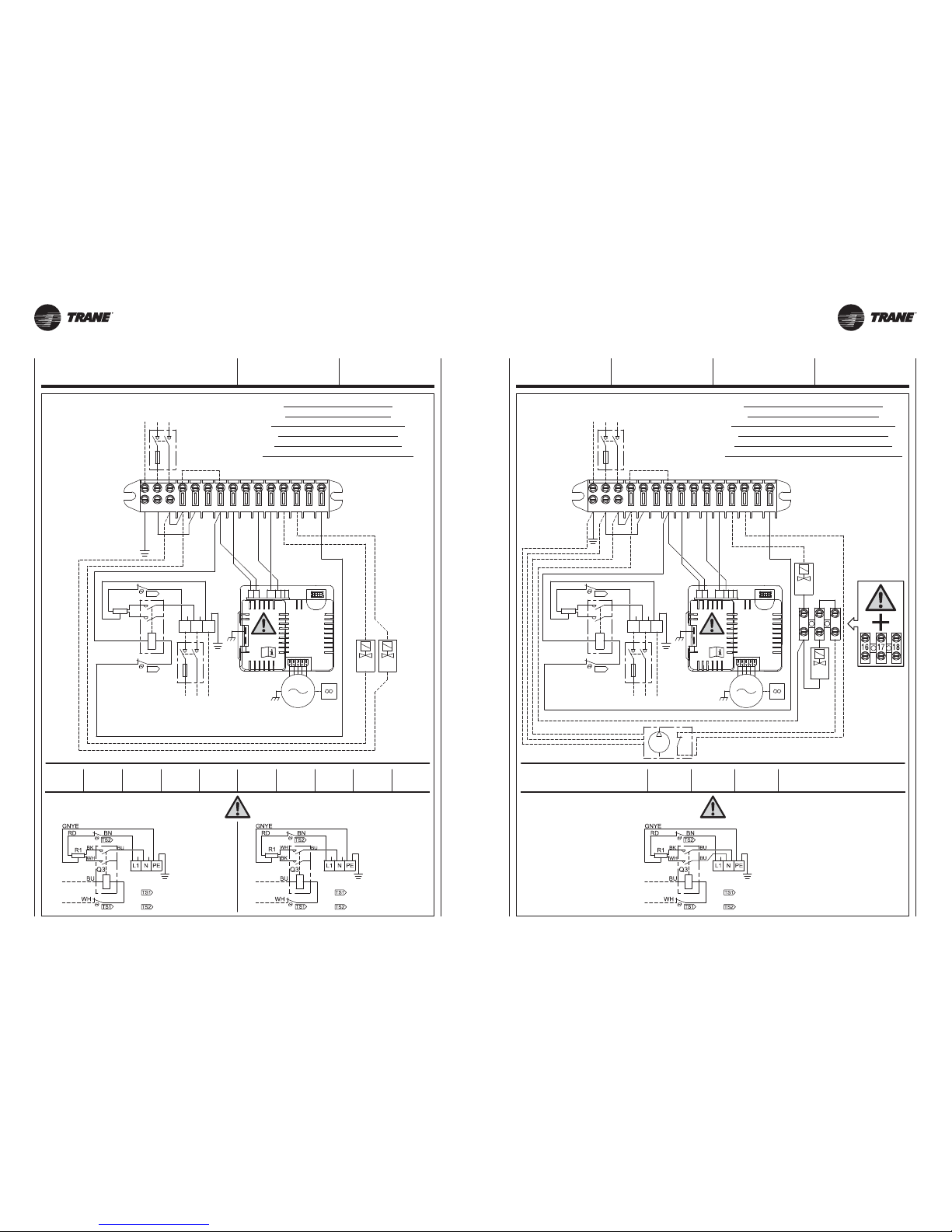
UNT-SVX26B-XX UNT-SVX26B-XX
DETTAGLIO COLLEGAMENTO ELETTRICO
ELECTRIC HEATER WIRING DETAIL
DÉTAILS RACCORDEMENT ÉLECTRIQUE
DETAIL DER ELEKTRISCHEN VERBINDUNG
DETALLES CONEXIÓN ELÉCTRICA
ELEKTRISCHE AANSLUITING DETAIL
Casing 2
1000 Watt
Casing 3
1500 Watt
Casing 4
2000 Watt
Casing 5
2500 Watt
Casing 6
2500 Watt
Thermal cut Off = 235°C
Automatic Reset
Thermal cut Off = 190°C
Manual Reset
B1
N
PE
MP
L
BK
BK
4
9
12
15
N
13
BK
11
14
L
PE
8107
56
BU
Q3
POWER
SUPPLY
230Vac 50Hz
L1NPE
Q2
L1NPE
R1
TS1
TS2
RD
GNYE
BK
WH
BU
VT
BU
BN
Q1
FCT
230V
50 Hz
PE
L
N
BU
BR
BU
GNYE
Y2
16 17 18
Y1
BK
WH
RD
BU
INVERTER
BLAC
BOARD
M
230V
50Hz
NL010
3
DETTAGLIO COLLEGAMENTO ELETTRICO
ELECTRIC HEATER WIRING DETAIL
DÉTAILS RACCORDEMENT ÉLECTRIQUE
DETAIL DER ELEKTRISCHEN VERBINDUNG
DETALLES CONEXIÓN ELÉCTRICA
ELEKTRISCHE AANSLUITING DETAIL
Casing 2
400 Watt
Casing 3
600 Watt
Casing 4
750 Watt
Casing 5
1000 Watt
Casing 6
1000 Watt
Casing 2
600 Watt
Casing 3
900 Watt
Casing 4
1250 Watt
Casing 5
1500 Watt
Casing 6
1500 Watt
Thermal cut Off = 190°C (Mod. 2−4)
Thermal cut Off = 160°C (Mod. 3−5−6)
Automatic Reset
Thermal cut Off = 235°C
Manual Reset
Thermal cut Off = 135°C
Automatic Reset
Thermal cut Off = 235°C
Manual Reset
N
L
PE
230V
50 Hz
FCT
Q1
BN
BU
BU
WH
BK
GNYE
RD
TS2
TS1
R1
PE
N
L1
Q2
PE
N
L1
POWER
SUPPLY
230Vac 50Hz
Q3
BU
65
7108
PE
L
14
GNYE
11
BK
13N15
12
9
4
Y2 Y1
VT
BK
RD
WH
BU
INVERTER
BLAC
BOARD
M
230V
50Hz
NL010
3
32 32A
SCHEMI
ELETTRICI
WIRING
DIAGRAMS
SCHEMAS
ELECTRIQUES SCHALTPLÄNE
ESQUEMAS
ELÉCTRICOS SCHAKELSCHEMA’S
Impianto 4 tubi + Batteria elettrica
4 pipe units + Electric resistance
Installation à 2 tubes + Batterie électrique
4-Leiter-Anlage + Electro-heizregister
Instalación a 4 tubos + Bateria electrica
Installatie met 4 leidingen + Elektrische batterij
Impianto 4 tubi + Batteria elettrica + pompa
4 pipe units + Electric resistance + pump
Installation à 2 tubes + Batterie électrique + pompe
4-Leiter-Anlage + Electro-heizregister + pumpe
Instalación a 4 tubos + Bateria electrica + bomba
Installatie met 4 leidingen + Elektrische batterij + pomp
Page 33
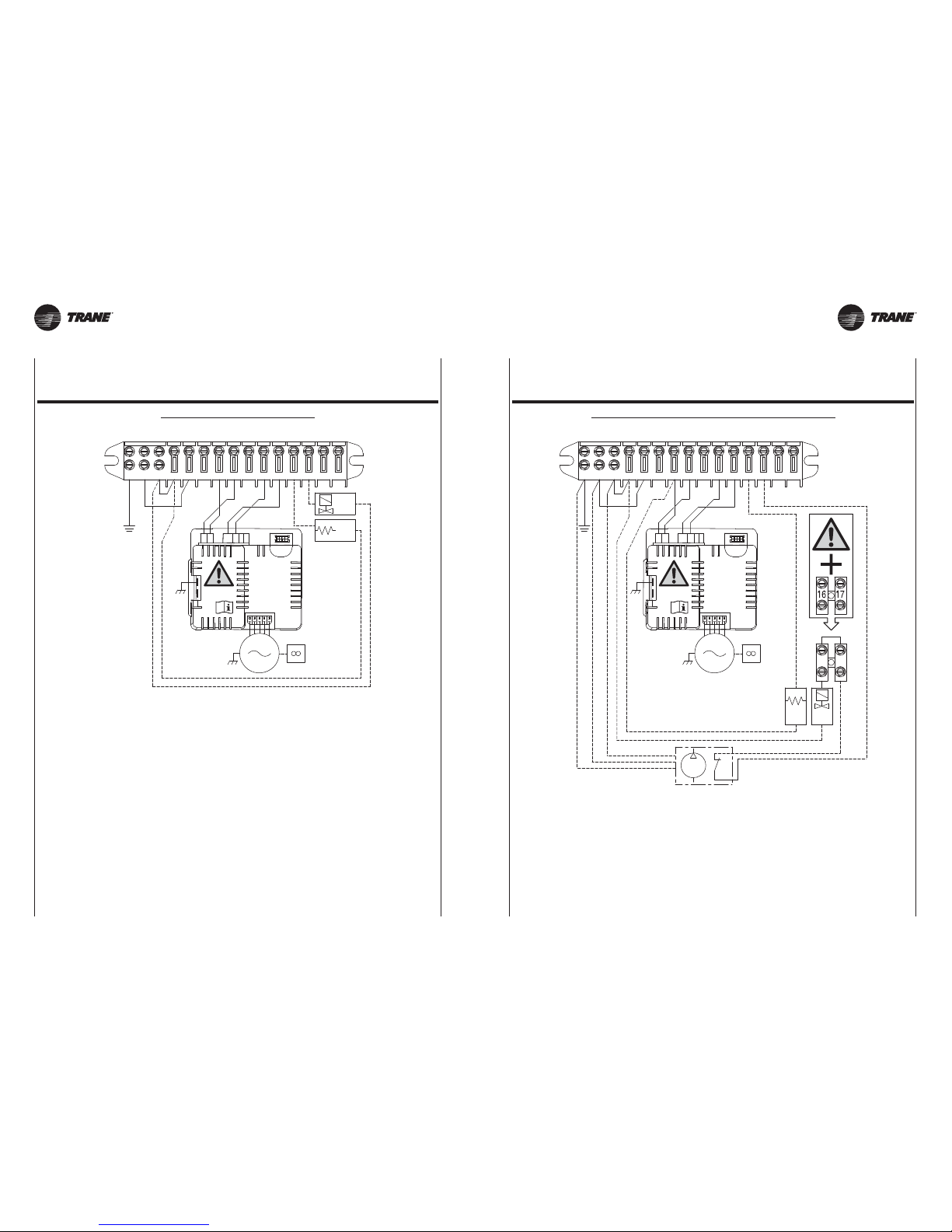
UNT-SVX26B-XX UNT-SVX26B-XX
FCT
16Y117
65
B1
7108
PE
MP
L
L
14
GNYE
11
BK
13
PE
N
15
12
N
9
BU
4
WH
RD
BU
BK
BK
BK
BU
BR
GNYE
EH
11
13
78
BU
GNYE
PE
9
6
L
BK
WH
5
10
EH
4
151214
N
BU
RD
Y1
BK
FCT
INVERTER
BLAC
BOARD
M
230V
50Hz
NL010
3
INVERTER
BLAC
BOARD
M
230V
50Hz
NL010
3
33 33A
“UT-ECM” type thermostat
Art. Nr. / Cód. / Code 35169939-001
SCHALTPLÄNE / ESQUEMAS ELÉCTRICOS / ELEKTRISCHE SCHEMA’S
“UT-ECM” type thermostat
Cod. / Code / Code 35169939-001
SCHEMI ELETTRICI / WIRING DIAGRAMS / SCHEMAS ELECTRIQUES
2 PIPES COOLING + ELECTRIC HEATER 2 PIPES COOLING + ELECTRIC HEATER + CONDENSATE PUMP
Page 34
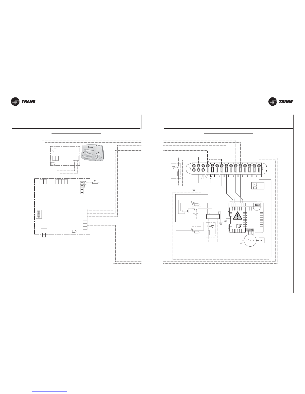
UNT-SVX26B-XX UNT-SVX26B-XX
INVERTER
BLAC
BOARD
M
230V
50Hz
NL010
3
T-EC
FCT
BN
BU
VT
BU
WH
BK
GNYE
RD
TS2
TS1
R1
PE
N
L1
Q2
PE
N
L1
POWER
SUPPLY
230Vac 50Hz
Q3
BU
65
7108
PE
L
14
GNYE
11
BK
13N15
12
9
4
Y1
BU
BK
WH
RD
LQ1PE
N
POWER
SUPPLY
230Vac
50Hz
L
B
UL
SEC1
B
IN1
T1
T1
-10
+0
M4
EV1
N
A
1
T3
A
M1
N
N
M5
EV2
M1
IN1P
M2
AUX
2
BA
1
CONFIGURATION
SW2
3
5
2
6
4
-10
EV1
EV2
+0
UL
L
N
-10
EV1
EV2
+0
UL
L
N
34 34A
“T-ECM” type thermostat
Art. Nr. / Cód. / Code 35169886-001
SCHALTPLÄNE / ESQUEMAS ELÉCTRICOS / ELEKTRISCHE SCHEMA’S
“T-ECM” type thermostat
Cod. / Code / Code 35169886-001
SCHEMI ELETTRICI / WIRING DIAGRAMS / SCHEMAS ELECTRIQUES
2 PIPES COOLING + ELECTRIC HEATER 2 PIPES COOLING + ELECTRIC HEATER
Page 35
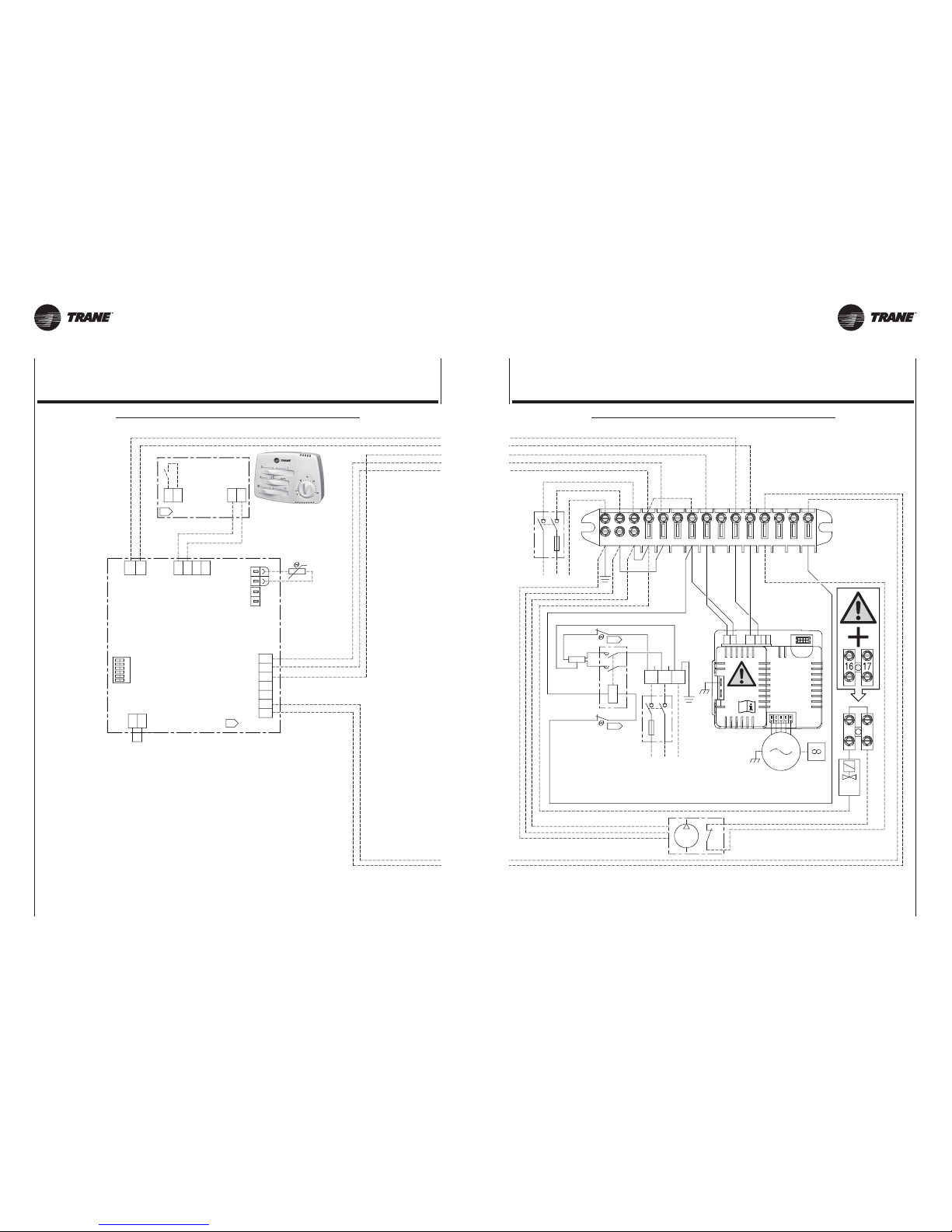
UNT-SVX26B-XX UNT-SVX26B-XX
INVERTER
BLAC
BOARD
M
230V
50Hz
NL010
3
T-EC
FCT
BN
BU
VT
BU
WH
BK
GNYE
RD
TS2
TS1
R1
PE
N
L1
Q2
PE
N
L1
POWER
SUPPLY
230Vac 50Hz
Q3
BU
65
7108
PE
L
14
GNYE
11
BK
13N15
12
9
4
LQ1PE
N
POWER
SUPPLY
230Vac
50Hz
BK
BK
L
MP
PE
N
BP
BU
GNYE
BU
BR
WH
RD
BK
BU
16 17
Y1
L
B
UL
SEC1
B
IN1
T1
T1
EV1
N
A
1
T3
A
M1
N
N
M5
EV2
M1
IN1P
M2
AUX
2
BA
1
CONFIGURATION
SW2
3
5
2
6
4
-10
+0
M4
EV1
EV2
-10
+0
UL
L
N
EV1
EV2
-10
+0
UL
L
N
35 35A
“T-ECM” type thermostat
Art. Nr. / Cód. / Code 35169886-001
SCHALTPLÄNE / ESQUEMAS ELÉCTRICOS / ELEKTRISCHE SCHEMA’S
“T-ECM” type thermostat
Cod. / Code / Code 35169886-001
SCHEMI ELETTRICI / WIRING DIAGRAMS / SCHEMAS ELECTRIQUES
2 PIPES COOLING + ELECTRIC HEATER + CONDENSATE PUMP 2 PIPES COOLING + ELECTRIC HEATER + CONDENSATE PUMP
Page 36
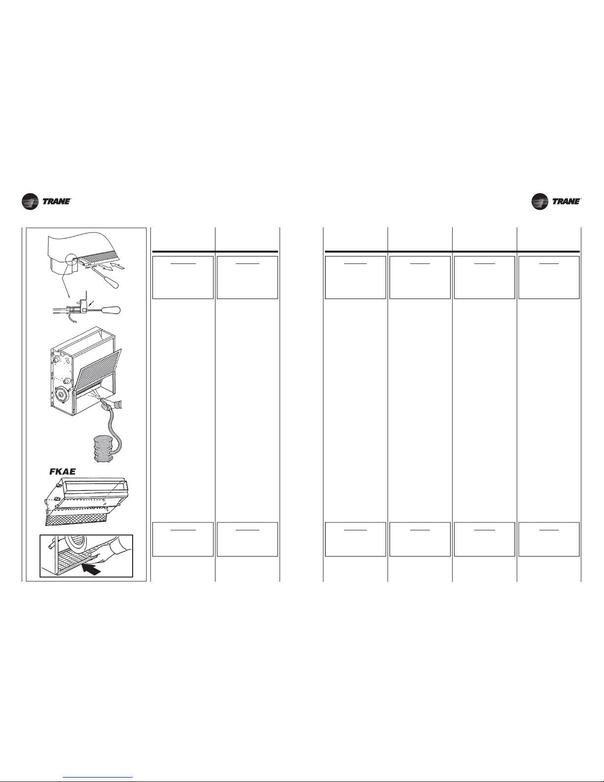
UNT-SVX26B-XX UNT-SVX26B-XX
ATTENZIONE!
RIMONTARE
SEMPRE IL FILTRO
DOPO
LA SUA PULIZIA.
IMPORTANT!
ALWAYS
REPLACE THE FILTER
AFTER CLEANING.
ATTENTION!
APRES L’AVOIR NETTOYE,
NE JAMAIS OUBLIER
DE REMONTER
LE FILTRE.
ACHTUNG!
NICHT VERGESSEN,
DEN FILTER NACH
DER REINIGUNG
WIEDER EINZUBAUEN.
ATENCIÓN!
DESPUÉS DE LIMPIARLO
VOLVER A MONTAR
SIEMPRE EL FILTRO
EN SU SITO.
OPGELET!
HERPLAATS DE FILTER
STEEDS NA EEN
SCHOONMAAKBEURT.
ATTENZIONE!
PRIMA DI QUALSIASI
PULIZIA
E MANUTENZIONE,
TOGLIERE
L’ALIMENTAZIONE
ALL’APPARECCHIO.
IMPORTANT!
BEFORE CARRYING OUT
CLEANING
OR MAINTENANCE,
MAKE SURE THE POWER
TO THE UNIT
IS TURNED OFF.
ATTENTION!
AVANT
TOUTE OPERATION
DE NETTOYAGE ET
D’ENTRETIEN,
COUPER L’ALIMENTATION
DE L’APPAREIL.
ACHTUNG!
VOR BEGINN
VON REINIGUNGS- UND
WARTUNGSEINGRIFFEN
MUSS DIE STROMZUFUHR
ZUM GERÄT
UNTERBROCHEN WERDEN.
ATENCIÓN!
ANTES DE EFECTUAR
CUALQUIER OPERACIÓN
DE LIMPIEZA
Y MANTENIMIENTO
CORTAR LA ALIMENTACIÓN
PARA EL APARATO.
OPGELET!
VOOR ELKE
SCHOONMAAK- EN
ONDERHOUDSBEURT,
DE STEKKER VAN HET
APPARAAT UIT HET
STOPCONTACT TREKKEN.
36 36A
PULIZIA,
MANUTENZIONE,
RICAMBI
CLEANING,
MAINTENANCE
AND SPARE PARTS
NETTOYAGE,
ENTRETIEN ET PIECES
DE RECHANGE
REINIGUNG,
WARTUNG,
ERSATZTEILE
LIMPIEZA,
MANTENIMIENTO,
RECAMBIOS
SCHOONMAAK,
ONDERHOUD,
WISSELSTUKKEN
Solo personale addetto alla manutenzione e precedentemente addestrato, può intervenire sulle apparecchiature.
ELETTROVENTILATORE:
Non richiede
alcun tipo di manutenzione.
BATTERIA:
Non richiede alcun tipo
di ordinaria manutenzione.
FILTRO:
Con l’ausilio di un utensile, sganciare il profilo portafiltro ed estrarre il
filtro dalle guide.
Si pulisce periodicamente usando
un’aspirapolvere oppure percuotendolo leggermente.
Sostituirlo nel caso non si possa più
pulire.
RICAMBI:
Per l’ordinazione delle parti di ricambio citare sempre il modello dell’apparecchio e la descrizione del componente.
Maintenance of the unit must be
carried out by trained maintenance
personnel only.
FAN:
No maintenance required.
HEAT EXCHANGER COIL:
No ordinary maintenance required.
FILTER:
Using a suitable tool, unhook the
filter holder strip and extract the filter
from the guides.
Clean regularly with a vacuum cleaner
or shake lightly.
When it can no longer be cleaned,
replace.
SPARE PARTS:
To order spare parts, always give the
model of appliance and a description
of the component.
Seul le personnel chargé de l’entretien
et ayant été formé dans ce but peut
intervenir sur les appareils.
VENTILATEUR:
Ne nécessite
aucun type d’entretien.
BATTERIE:
Ne nécessite
aucun type d’entretien ordinaire.
FILTRE:
Au moyen d’un outil, décrocher le
profilé portefiltre et retirer le filtre de
ses guides.
Doit être nettoyé périodiquement à
l’aide d’un aspirateur ou en le frappant
légèrement.
Le remplacer lorsqu’il n’est plus
possible de le nettoyer.
PIECES DE RECHANGE:
Pour la commande des pièces de
rechange, indiquer toujours le modèle de l’appareil et la description
du composant.
Nur speziell ausgebildetes Fachpersonal ist befugt, an den Geräten
zu arbeiten.
ELEKTROVENTILATOR:
Dieser erfordert keinerlei Wartung.
REGISTER:
Dieses erfordert keine regelmäßige
Wartung.
FILTER:
Mit Hilfe eines Werkzeugs das Filterhalteprofil lösen und den Filter aus
den Führungen nehmen.
Regelmäßig mit einem Staubsauger
reinigen oder vorsichtig ausklopfen.
Wenn der Filter nicht mehr gesäubert
werden kann, muss er ersetzt werden.
ERSATZTEILE:
Bei der Ersatzteilbestellung stets
das betreffende Gerätemodell und
die Bezeichnung der Komponente
angeben.
Sólo el personal destinado al mantenimiento y previamente formado,
puede intervenir sobre los equipos.
ELECTROVENTILADOR:
No requiere
ningún tipo de mantenimiento.
BATERÍA:
No requiere ningún tipo
de mantenimiento ordinario.
FILTRO:
Con la ayuda de una herramienta,
desenganchar el perfil portafiltro y
extraer el filtro de las guías.
Se limpia periódicamente usando
un aspirador o bien golpeándolo
ligeramente.
Sustituirlo en caso de que ya no se
pueda limpiar.
RECAMBIOS:
Para pedir las piezas de recambio
citar siempre el modelo del aparato
y la descripción del componente.
Alleen personeel dat bevoegd is voor
het onderhoud en een degelijke
opleiding genoten heeft, mag werken
aan de apparatuur.
ELEKTROVENTILATOR:
Vergt geen enkel type onderhoud.
BATTERIJ:
Vergt geen enkel type gewoon
onderhoud.
FILTER:
Met behulp van een gereedschap,
haakt u de filterhouder los en haalt
u hem uit zijn zitting.
Maak de filter regelmatig schoon met
een stofzuiger of door er zacht op te
kloppen.
Vervang de filter indien hij niet kan
worden schoongemaakt.
WISSELSTUKKEN:
Bij de bestelling van de wisselstukken,
vermeldt u steeds het model van het
apparaat en beschrijft u het odnerdeel.
Page 37
UNT-SVX26B-XX UNT-SVX26B-XX37 37A
RICERCA GUASTI TROUBLESHOOTING DEPANNAGE FEHLERSUCHE
INVESTIGACIÓN
DE AVERÍAS
OPSPOREN
DEFECTEN
GUASTO
1 - Il motore non gira
o gira in modo non corretto.
RIMEDIO
- Controllare che
l’alimentazione sia inserita.
- Verificare il collegamento
corretto dei fili, osservando
gli schemi elettrici.
- Verificare la posizione
dell’interruttore generale,
del commutatore stagionale
e del termostato.
GUASTO
2 - L’apparecchio
non scalda/raffredda più
come in precedenza.
RIMEDIO
- Controllare che il filtro
sia sufficientemente pulito.
- Verificare sfiatando la batteria
che non sia entrata aria
nel circuito idraulico.
GUASTO
3 - L’apparecchio perde acqua.
RIMEDIO
- Controllare che l’inclinazione
sia in direzione
dello scarico condensa.
- Controllare
che lo scarico condensa
non sia ostruito.
PROBLEM
1 - The motor does not rotate
or rotates incorrectly.
REMEDY
- Make sure
the power to the unit is on.
- Make sure the wires
are correctly connected,
referring to the wiring diagram.
- Control if the main switch,
the seasonal commutator
and the thermostat
are in the right position.
PROBLEM
2 - The unit does not heat/cool
as before.
REMEDY
- Make sure the filter is clean.
- Make sure the hydraulic circuit
is free from air by venting
the heat exchanger.
PROBLEM
3 - The appliance leaks water.
REMEDY
- Make sure
it is sloping in the direction
of the condensate drain.
- Make sure
the condensate drain
is not clogged.
DEFAUT
1 - Le moteur ne tourne pas ou
tourne de manière incorrecte.
ACTION CORRECTIVE
- Contrôler que
l’alimentation est branchée.
- Vérifier le bon raccordement
des conducteurs à l’aide
des schémas électriques.
- L’interrupteur général
et le commutateur saisonnier
soient dans
la position correcte.
DEFAUT
2 - L’appareil
ne chauffe ou ne refroidit plus
comme avant.
ACTION CORRECTIVE
- Contrôler que le filtre
est suffisamment propre.
- Vérifier, en purgeant la
batterie, que de l’air n’est pas
entré dans le circuit hydraulique.
DEFAUT
3 - L’appareil perd de l’eau.
ACTION CORRECTIVE
- Contrôler que l’évacuation
des condensats est inclinée
dans la bonne direction.
- Contrôler que
l’évacuation des condensats
n’est pas bouchée.
STÖRUNG
1 - Der Motor dreht nicht
oder dreht nicht korrekt.
ABHILFE
- Kontrollieren, ob die Spannungs versorgung zugeschaltet ist.
- Auf Grundlage der Schaltpläne
den korrekten Anschluss
der Drähte prüfen.
- Die Position des Haupt schalters, des Umschalters
der Betriebsart und
des Thermostats kontrollieren.
STÖRUNG
2 - Das Gerät heizt/kühlt nicht
mehr wie zuvor.
ABHILFE
- Kontrollieren, ob der Filter
sauber genug ist.
- Durch Entlüften des Registers
kontrollieren, ob Luft in den
Wasserkreis eingedrungen ist.
STÖRUNG
3 - Das Gerät verliert Wasser.
ABHILFE
- Kontrollieren, ob
die Schräge in Richtung des
Kondensatabflusses verläuft.
- Kontrollieren, ob
der Kondensatabfluss
frei ist.
AVERÍA
1 - El motor no gira
o gira de modo incorrecto.
SOLUCIÓN
- Verificar que esté conectado
a la toma de corriente.
- Verificar la correcta conexión
de los hilos, observando
los esquemas eléctricos.
- Verificar la posición
del interruptor general,
del conmutador estacional
y del termostato.
AVERÍA
2 - El aparato
ya no calienta/enfría
como con anterioridad.
SOLUCIÓN
- Verificar que el filtro
esté bien limpio.
- Verificar purgando la batería
que no haya entrado aire
en el circuito hidráulico.
AVERÍA
3 - El aparato pierde agua.
SOLUCIÓN
- Controlar que esté inclinado
en dirección a la evacuación
del agua de condensación.
- Controlar que la evacuación
del agua de condensación
no esté obstruida.
DEFECT
1 - De motor draait niet
of op niet correcte wijze.
OPLOSSING
- Controleer of de stekker
in het stopcontact zit.
- Controleer de correcte
aansluiting van de draden,
conform de schakelschema’s.
- Controleer de positie
van de hoofdschakelaar,
de seizoensschakelaar
en de thermostaat.
DEFECT
2 - Het apparaat
verwarmt/koelt niet
meer af zoals voordien.
OPLOSSING
- Controleer of de filter
voldoende schoon is.
- Tap de batterij af en ga
de aanwezigheid na van lucht
in het hydraulisch circuit.
DEFECT
3 - Er lekt water uit het apparaat.
OPLOSSING
- Controleer of de helling in de
richting van de afvoerbuis voor
het condensatievocht loopt.
- Controleer of de afvoerbuis
voor het condensatievocht
niet verstopt is.
Page 38
UNT-SVX26B-XX UNT-SVX26B-XX
100 800600400300200 1000806050
1
40
30
20
9
8
7
6
5
60
4
3
2
10
50
3
4
5-6
2
100 800600400300200 1000806050
1
40
30
20
9
8
7
6
5
60
4
3
2
10
50
3
4
5-6
2
100 800600400300200 15001000
1
40
30
20
9
8
7
6
5
50
4
3
2
10
34
52
64
44
22
100 800600400300200 15001000
1
40
30
20
9
8
7
6
5
50
4
3
2
10
33
51
63
43
21
38 38A
PERDITE DI CARICO LATO ACQUA / PRESSURE DROP TABLE
PERTES DE CHARGE CÔTE EAU / DRUCKVERLUSTE WASSER
PÉRDIDAS DE CARGA LADO AGUA / WATERLEKKEN
PERDITE DI CARICO LATO ACQUA / PRESSURE DROP TABLE
PERTES DE CHARGE CÔTE EAU / DRUCKVERLUSTE WASSER
PÉRDIDAS DE CARGA LADO AGUA / WATERLEKKEN
Batteria a 3 ranghi
3 row battery
Batterie à 3 rangs
Register mit 3 Rohrreihen
Batería de 3 filas
Batterij met 3 rijen
Batteria a 4 ranghi
4 row battery
Batterie à 4 rangs
Register mit 4 Rohrreihen
Batería de 3 filas
Batterij met 4 rijen
K
0,94 0,90 0,86 0,82 0,78 0,74 0,70
20 30 40 50 60 70 80
°C
La perdita di carico si riferisce ad una temperatura media dell’acqua di 10°C;
per temperature diverse, moltiplicare la perdita di carico per il coefficiente K riportato in tabella.
The table indicates the pressure drop for a mean water temperature of 10°C.
For different water temperatures multiply by the correction factors K.
La perte de charge se référe à une température moyenne d’eau de 10°C.
Pour une température différente, multiplier la perte de charge par le coefficient K de le table suivante.
Der Druckverlust bezieht sich auf eine durchschnittliche Temperatur des Wassers von 10°C;
für abweichende Temperaturen den Druckverlust mit dem Koeffizienten K der Tabelle multiplizieren.
La pérdida de carga se refiere a una temperatura media del agua de 10°C;
para temperaturas distintas multiplicar la pérdida de carga por el coeficiente K que figura en la tabla.
Het energieverlies verwijst naar een gemiddelde watertemperatuur van 10°C;
bij verschillende temperaturen vermenigvuldigt u het energieverlies met de coëfficiënt K die u in de tabel vindt.
Dp - kPa
Portata acqua (l/h) - Water flow (l/h)
Débit d’eau (l/h) - Wasserdurchflussmenge (l/h)
Caudal de agua (l/h) - Waterdebiet (l/h)
Portata acqua (l/h) - Water flow (l/h)
Débit d’eau (l/h) - Wasserdurchflussmenge (l/h)
Caudal de agua (l/h) - Waterdebiet (l/h)
Dp - kPa
Batteria addizionale a 1 rango
1 row additional battery
Batterie additionnelle à 1 rang
Zusatzregisters mit 1 Rohrreihe
Batería adicional de 1 fila
Extra batterij met 1 rij
Batteria addizionale a 2 ranghi
2 row additional battery
Batterie additionnelle à 2 rangs
Zusatzregisters mit 1 Rohrreihen
Batería adicional de 2 filas
Extra batterij met 2 rijen
K
1,14 1,08 1,02 0,96 0,90
°C
40 50 60 70 80
La perdita di carico si riferisce ad una temperatura media dell’acqua di 65°C;
per temperature diverse, moltiplicare la perdita di carico per il coefficiente K riportato in tabella.
The table indicates the pressure drop for a mean water temperature of 65°C.
For different water temperatures multiply by the correction factors K.
La perte de charge se référe à une température moyenne d’eau de 65°C.
Pour une température différente, multiplier la perte de charge par le coefficient K de le table suivante.
Der Druckverlust bezieht sich auf eine durchschnittliche Temperatur des Wassers von 65°C;
für abweichende Temperaturen den Druckverlust mit dem Koeffizienten K der Tabelle multiplizieren.
La pérdida de carga se refiere a una temperatura media del agua de 65°C;
para temperaturas distintas multiplicar la pérdida de carga por el coeficiente K que figura en la tabla.
Het energieverlies verwijst naar een gemiddelde watertemperatuur van 65°C;
bij verschillende temperaturen vermenigvuldigt u het energieverlies met de coëfficiënt K die u in de tabel vindt.
Portata acqua (l/h) - Water flow (l/h)
Débit d’eau (l/h) - Wasserdurchflussmenge (l/h)
Caudal de agua (l/h) - Waterdebiet (l/h)
Portata acqua (l/h) - Water flow (l/h)
Débit d’eau (l/h) - Wasserdurchflussmenge (l/h)
Caudal de agua (l/h) - Waterdebiet (l/h)
Dp - kPa
Dp - kPa
Page 39
Trane optimizes the performance of homes and buildings around the world. A business of Ingersoll Rand,
the leader in creating and sustaining safe, comfortable and energy efficient environments, Trane offers
a broad portfolio of advanced controls and HVAC systems, comprehensive building services, and parts.
For more information, visit www.Trane.com.
Trane has a policy of continuous product and product data improvement and reserves the right to change design and specifications
without notice.
© 2014 Trane All rights reserved
UNT-SVX26B-XX September 01, 2014 Supersedes: UNT-SVX26A-XX July 01, 2013
Digitally printed on environmentally friendly paper;
produced using fewer trees and chemicals and less energy.
 Loading...