

Page 1
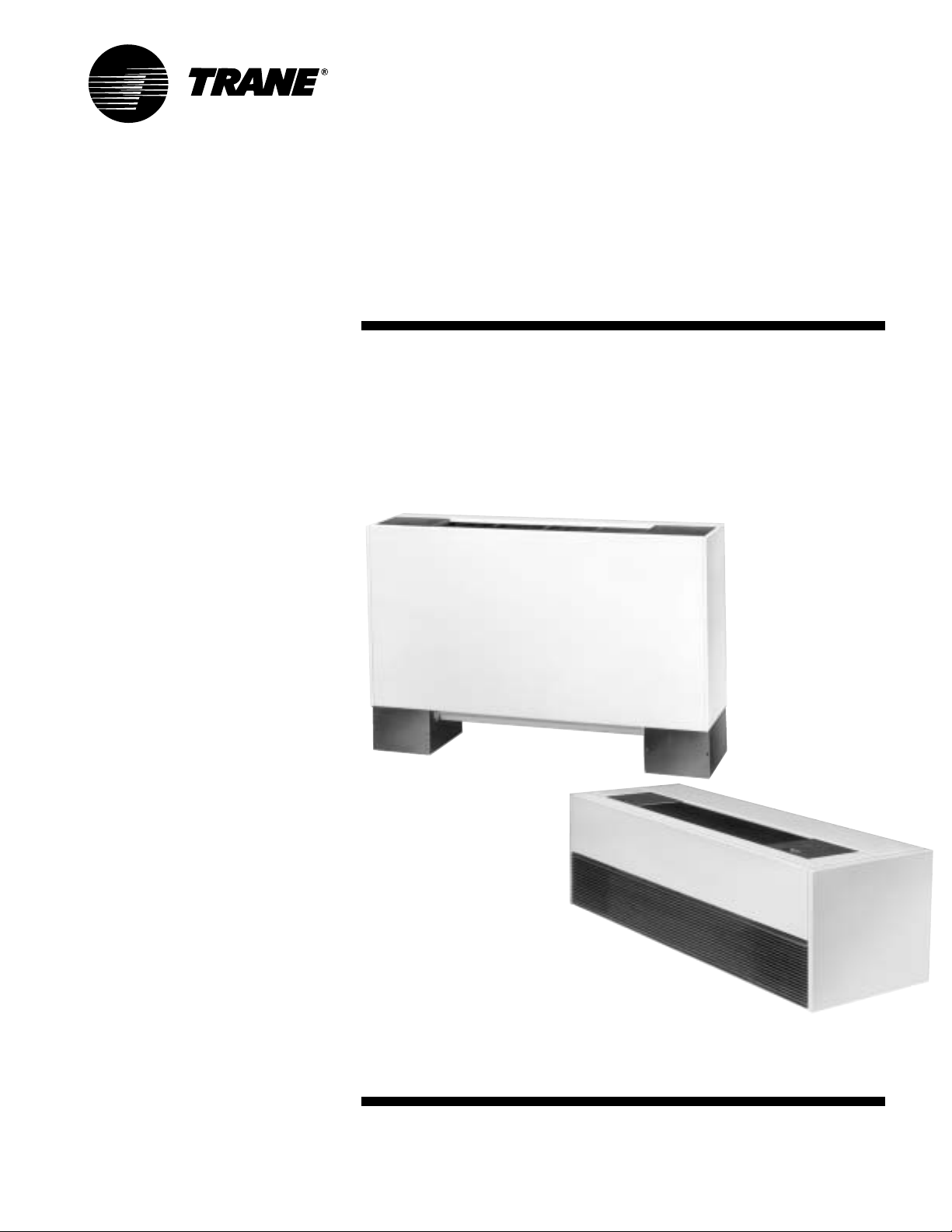
Installation, Operation,
and Maintenance
UniTrane Fan-Coil & Force Flo
Air Conditioners
200 to 1,200 cfm
Models FC & FF
“ZO” and later design sequence
Low vertical models FCKB & FCLB:
“SO” and later design sequence
April 2005
UNT -SVX07A-EN
Page 2

general
information
About This Manual
Literature Change History
Use this manual for UniT rane fan-coils
and Force Flo cabinet heaters. This is the
seventh revision of this manual. It
provides specific installation, operation,
and maintenance instructions for “ZO”
and later design sequences for all
models except low vertical, which are
“SO” and later design sequences. For
previous design sequence information,
contact your local T rane representative.
Warnings and Cautions
Warnings and cautions appear at
appropriate sections throughout this
manual. Read these carefully.
WARNING
Indicates a potentially hazardous
situation, which could result in death
or serious injury if not avoided.
CAUTION
Indicates a potentially hazardous
situation, which may result in minor
or moderate injury if not avoided.
Also, it may alert against unsafe
practices.
WARNING
Hazardous V oltage w/Capacitors!
Disconnect all electric power,
including remote disconnects and
discharge all motor start/run
capacitors before servicing. Follow
proper lockout/tagout procedures to
ensure the power cannot be
inadvertently energized. For variable
frequency drives or other energy
storing components provided by
Trane or others, refer to the
appropriate manufacturer’s literature
for allowable waiting periods for
discharge of capacitors. Verify with an
appropriate voltmeter that all
capacitors have discharged. Failure to
disconnect power and discharge
capacitors before servicing could
result in death or serious injury.
CAUTION
Use Copper Conductors Only!
Unit terminals are not designed to
accept other type conductors. Failure
to use copper conductors may result
in equipment damage.
Common HVAC Acronyms
For convenience, a number of acronyms
and abbreviations are used throughout
this manual. These acronyms are
alphabetically listed and defined below.
BAS = Building automation systems
cfm = Cubic-feet-per-minute
ewt = entering water temperature
F/A = Fresh air
HV AC = Heating, ventilation and air
conditioning
I/O = Inputs/outputs
IOM= Installation, operation, and
maintenace manual
LH = Left-hand
O/A = Outside air
R/A = Return air
RH = Right-hand
rpm = Revolutions-per-minute
S/A = Supply air
w.c. = W ater column
ZSM = Zone sensor module
CAUTION
Indicates a situation that may result
in equipment or property-damageonly accidents.
© 2005 American Standard Inc. UNT-SVX07A-EN
Page 3

contents
Cross reference to related publications/information for UniT rane™ fan-coil & Force
Flo™ equipment:
• Rover™ Installation, Operation and Programming Guide, EMTX-SVX01D-EN
™
• T racer
• T racer
• UniT rane™ Fan-Coil Catalog, UNT -PRC001-EN
• Force Flo
Installation ……………………………………………………………2
Operation ……………………………………………………………49
ZN510 Unit Controller , CNT -IOP-1
™
ZN520 Unit Controller, CNT-SVX04A-EN
™
Cabinet Heater Catalog, CAB-PRC001-EN
general information ……………………………………………2
dimensions & weights ……………………………………… 10
pre-installation considerations ………………………………28
mechanical requirements ……………………………………30
electrical requirements ………………………………………36
installation procedure ………………………………………41
pre-startup requirements ……………………………………46
general information …………………………………………49
sequence of operation ………………………………………50
Maintenance…………………………………………………………60
diagnostics ……………………………………………………60
troubleshooting ………………………………………………64
maintenance procedures ……………………………………67
typical wiring diagrams ………………………………………71
UNT-SVX07A-EN 3
Page 4
general
information
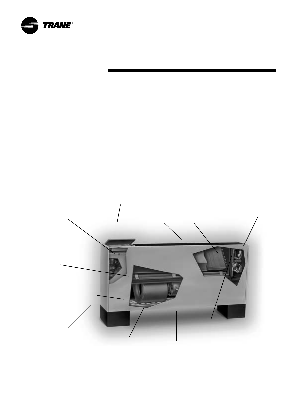
General
UniT rane fan-coil and Force Flo units are
intended for single zone applications.
These units have load capabilities of 200
to 1200 cfm. See Figure I-GI-1 for unit
components. Fan-coil units are available
as two-pipe, with or without electric heat
(one hydronic circuit) or four-pipe (two
hydronic circuits). Force-Flo units feature
two-pipe hydronic, electric heat only, or
steam only. Also, these units feature a
variety of factory mounted piping
packages.
Units with the three-speed fan switch
only, are available with the switch
mounted on the unit, or shipped separately, to be mounted in the occupied
space. The unit mounted three-speed
Factory installed
and tested controls
switch option, can be ordered with a low
voltage(24 volts AC) transformer and
three fan speed relays. The ship seperate
three-speed switch option, only comes
with a low voltage (24 volt AC) transformer and three fan speed relays.
The T racer ZN010, ZN510, and ZN520
controllers are included inside the units
control box assembly. These controllers
utilize analog signals from a unit-mounted
control device or from a control device
mounted in the occupied space.
The controls interface option, includes a
24 volt AC transformer , and an interface
terminal board. Controls provided by an
external source, can be tied into the
interface terminal board, utilizing
female spade connectors.
Smaller unit footprint
Quiet operation
1
/4"
T wo, three or
four-row coils
Model Number
Each UniT rane fan-coil and Force-Flo
cabinet heater has a multiple character
model number unique to that particular
unit. T o determine a unit’s specific options,
reference the model number on the unit
nameplate on the fan scroll. The unit
nameplate also identifies the serial
number, sales order number, and
installation and operating specifications.
Following is a complete description of the
fan-coil model number. Each digit in the
model number has a corresponding code
that identifies specific unit options.
Factory assembled,
installed and tested piping
package with IAQ drain pan
to collect condensate
Removable, noncorrosive,
positively-sloped drain pan that’s
easy to clean
Easy to remove fan assembly
Cleanable closed-
16-gage steel construction
Easy filter access
without front panel
removal
Figure I-GI-1. UniTrane fan-coil unit components. Vertical cabinet model is shown.
4 UNT-SVX07A-EN
Damper allows up
to 100% fresh air
cell insulation (nonfiberglass)
Page 5
general
Installation
information
Model Number Description
FC B B 020 1 C P0 A 0 G 1 0 A A 2 M 000 0 0 1 0 0 0 A A 000 000 0 0 0 0 A 0 0
1 5 10 15 20 25 30 35 40 44
Digits 1, 2 — unit type
FC = fan-coil
FF = force flo
Digit 3 — cabinet type
A = vertical concealed
B = vertical cabinet
C = horizontal concealed
D = horizontal cabinet
E = horizontal recessed
F = vertical wall hung
H = vertical recessed
J = vertical cabinet slope top
K = low vertical concealed
L = low vertical cabinet
M = inverted vertical cabinet
N = inverted vertical recessed
Digit 4 — development sequence “B”
Digits 5, 6, 7 — unit size
020 040 080
030 060 100
120
Digit 8 — unit voltage
1 = 115/60/1 4 = 230/60/1
2 = 208/60/1 9 = 220/50/1
3 = 277/60/1
Digit 9 — piping system/placement
A = no piping, RH, w/o aux drn pan
B = no piping, LH, w/o aux drn pan
C = no piping, RH, w/ aux drn pan
D = no piping, LH, w/ aux drn pan
E = no piping, RH, w/o aux drn pan,
extended end pocket
F = no piping, LH, w/o aux drn pan,
extended end pocket
G = no piping, RH, w/ aux drn pan,
extended end pocket
H = no piping, LH, w/ aux drn pan,
extended end pocket
J = piping package, RH
K = piping package, LH
L = piping package, RH, extd end pkt
M = piping package, LH, extd end pkt
Digits 10, 11 — design sequence
Digit 12 — inlets
A = front toe space
B = front bar grille
C = front stamped louver
D = bottom stamped louver
E = bottom toe space
F = back duct collar
G = back open return
H = back stamped louver
Digit 13 — fresh air damper
0 = none
A = manual, bottom opening
B = manual, back opening
C = manual, top opening
D = auto, 2-position, bottom opening
E = auto, 2-position, back opening
F = auto, 2-position, top opening
G = auto, economizer, bottom opening
H = auto, economizer, back opening
J = auto, economizer , top opening
K = no damper , bottom opening
L = no damper , back opening
M= no damper, top opening
Digit 14 — outlets
A = front duct collar
B = front bar grille
C = front stamped louver
D = front quad grille
G = top quad grille
H = top bar grille
J = top duct collar
Digit 15 — color
0 = no paint (concealed units only)
1 = deluxe beige 4 = driftwood grey
2 = soft dove 5 = stone grey
3 = cameo white 6 = rose mauve
Digit 16 — tamperproof locks/leveling
feet
0 = none
A = locking panel
B = keylock access door
C = locking panel & keylock access door
D = leveling feet
F=
locking panel w/ leveling feet
G = keylock panel, keylock access door
w/ leveling feet
Digit 17 — motor
A = free discharge
B = high static
Digit 18 — coil
A = 2 row cooling/heating
B = 3 row cooling/heating
C = 4 row cooling/heating
D = 2 row cooling/1 row heating
E = 2 row cooling/2 row heating
F = 3 row cooling/1 row heating
G = 2 row cooling only
H = 3 row cooling only
J = 4 row cooling only
K = 2 row cooling/heating w/ elec heat
L = 3 row cooling/heating w/ elec heat
M= 4 row cooling/heating w/ elec heat
P = 2 row cooling/heating w/1 row heat
Q = 2 row cooling/heating w/2 row heat
R = 3 row cooling/heating w/1 row heat
Digit 19 — coil series
2 = 144 FPF
Digit 20 — coil air vent
A = automatic air vent
M= manual air vent
Digits 21, 22, 23 — electric heat (208V
derate)
000 = no electric heat
010 = 1.0 kW (0.75 kW)
015 = 1.5 kW (1.1 kW)
020 = 2.0 kW (1.5 kW)
025 = 2.5 kW (1.9 kW)
030 = 3.0 kW (2.3 kW)
040 = 4.0 kW (3.0 kW)
050 = 5.0 kW (3.8 kW)
060 = 6.0 kW (4.5 kW)
070 = 7.0 kW (5.3 kW)
08 0= 8.0 kW (6.0 kW)
100 = 10.0 kW
Digit 24 — reheat coil
0 = none B = hot water coil
A = steam coil
Digit 25 — disconnect switch
0 = none
D = disconnect switch
Digit 26 — filter
0= none
1= 1” throwaway filter
2= 1” throwaway pleated media filter
3= 1” throwaway, qty 2
4=
1” throwaway pltd media, qty 2
5= 1” throwaway, qty 3
6= 1” throwaway pltd media, qty 3
7= 1” throwaway, qty 4
8= 1” throwaway pltd media, qty 4
Digit 27 — main control valve
0 = none
A = 2-way, 2-position, NO (30 psig)
B = 3-way , 2-position, NO (28 psig)
C = 2-way , 2-position, NC (30 psig)
D = 3-way, 2-position, NC (20 psig)
E = 2-way, 2-position, NO (50 psig)
F = 3-way , 2-position, NO (28 psig)
G = 2-way, 2-position, NC (50 psig)
H = 3-way, 2-position, NC (28 psig)
UNT-SVX07A-EN 5
Page 6
general
J = 2-way , modulating, 0.7 Cv (50 psig)*
K = 3-way , modulating, 0.7 Cv (50 psig)*
L = 2-way, modulating, 1.1 Cv (60 psig)*
M= 3-way, modulating, 1.1 Cv (60 psig)*
N = 2-way, modulating, 2.3 Cv (60 psig)*
P = 3-way, modulating, 2.7 Cv (60 psig)*
Q = 2-way, modulating, 3.3 Cv (60 psig)*
R = 3-way, modulating, 3.8 Cv (60 psig)*
X = field-supplied, NO
Y = field-supplied, NC
Z = field-supplied 3-wire modulating
Digit 28 — auxiliary control valve
0 = none
A = 2-way, 2-position, NO (30 psig)
B = 3-way, 2-position, NC (28 psig)
C = 2-way, 2-position, NC (30 psig)
D = 3-way, 2-position, NC (20 psig)
E = 2-way, 2-position, NO (50 psig)
F = 3-way, 2-position, NO (28 psig)
G = 2-way, 2-position, NC (50 psig)
H = 3-way, 2-position, NC (28 psig)
J = 2-way, modulating, 0.6 Cv (60 psig)
K = 3-way, modulating, 0.6 Cv (60 psig)
L = 2-way, modulating, 1.1 Cv (60 psig)
M= 3-way, modulating, 1.1 Cv (60 psig)
N = 2-way, modulating, 2.3 Cv (60 psig)
P = 3-way, modulating, 2.7 Cv (60 psig)
Q = 2-way, modulating, 3.3 Cv (60 psig)
R = 3-way, modulating, 3.8 Cv (60 psig)
X = field-supplied, NO
Y = field-supplied, NC
Z = field-supplied 3-wire modulating
Digit 29 — piping packages
0 = none
A = basic ball valve S & R
B = basic ball valve S/man. crkt set
C = basic ball valve S & R w/auto crkt set
D = deluxe ball valve S & R
E = deluxe ball valve S /man. crkt set R
F = deluxe ball valve S & R w/auto crkt set
Digit 30 — control type
0 = none
A = fan speed switch
E = T racer ZN010
F = Tracer ZN510
Installation
G = T racer ZN520
H = CSTI
Digit 31 — control option
D = unit mtd fan mode, unit voltage,
K = wall mtd fan mode
V = unit mtd fan sp w/ setpnt
X = unit mtd fan sp w/ wall mtd setpnt
Y = unit mtd fan sp & wall mtd setpnt w/
comm.
Z = unit mtd fan sp, on/cancel, setpnt w/
comm.
1 = wall mtd on/cancel w/ comm.
2 = wall mtd fan speed, setpnt, on/cancel
w/ comm.
3 = unit mtd fan speed switch, low voltage
4 = wall mtd digital zone sensor , fan sp w/
setpnt, on/cancel, comm.
5 = wall mtd digital zone sensor, setpnt,
on/cancel, comm.
Digit 32 — IAQ options
0 = none
1 = dehumidification
4 = dehumidification w/sensor
Digit 33 — cntrl function #1
0 = w/o exhaust fan/damper or alarm
Digit 34 — cntrl function #2
0 = w/o occupant call or IAQ status
Digit 35 — control function #3
0 = none
1 = occ/unocc control
2 = condensate overflow detection
3 = occ/unocc & condensate overflow
Digit 36 — cntrl function #4
0 = none
1 = smoke input
2 = low temperature detection
3 = smoke input & low limit sensor
information
Digits 37, 38 — future cntrl functions
Digit 39 —
0 = none
5
/8”standard vertical recessed panel
A =
B = 2” projection panel
C = 2.5” projection panel
D = 3” projection panel
E = 3.5” projection panel
F = 4” projection panel
G = 4.5” projection panel
H = 5” projection panel
J = 5.5”projection panel
K = 6” projection panel
L = 2”falseback
M = 3” falseback
N = 4” falseback
P = 5” falseback
Q = 6” falseback
R = 7” falseback
T = 8” falseback
Digit 40 — main autoflow gpm
A = 0.5 G = 3.0 N = 7.0
B = 0.75 H = 3.5 P = 8.0
C = 1.0 J = 4.0 Q = 9.0
D = 1.5 K = 4.5 R = 10.0
E = 2.0 L = 5.0 T = 11.0
F = 2.5 M= 6.0 U = 12.0
Digit 41 — auxiliary autoflow gpm
A = 0.5 F = 2.5 L = 5.0
B = 0.75 G= 3.0 M= 6.0
C = 1.0 H = 3.5 N = 7.0
D = 1.5 J = 4.0 P = 8.0
E = 2.0 K = 4.5
Digit 42 — subbase
0 = none
A = 2” subbase D =5” subbase
B = 3” subbase E =6” subbase
C = 4” subbase F =7” subbase
Digit 43 — recessed flange
0 = none
A = recessed flange
Digit 44 — wall boxes
0 = none
A = anodized wall box
projection panel/falseback
6 UNT-SVX07A-EN
Page 7
general
Installation
information
Table I-GI-1. Fan-coil component data
unit size 02 03 04 06 08 10 12
Coil Data
Face Area — Ft
LxDxH — In. (cm)
2-Row 15x1.7x8 15x1.7x8 20x1.7x8 29.5x1.7x8 38x1.7x8 57x1.7x8 57x1.7x8
3-Row 15x2.6x8 15x2.6x8 20x2.6x8 29.5x2.6x8 38x2.6x8 57x2.6x8 57x2.6x8
4-Row 15x3.5x8 15x3.5x8 20x3.5x8 29.5x3.5x8 38x3.5x8 57x3.5x8 57x3.5x8
Volume — Gal. (Liters)
1-Row (Heat) .06 (.23) .06 (.23) .08 (.30) .11 (.42) .14 (.53) .21 (.79) .21 (.79)
2-Row .12 (.45) .12 (.45) .15 (.57) .22 (.83) .28 (1.06) .42 (1.59) .42 (1.59)
3-Row .18 (.68) .18 (.68) .23 (.87) .33 (1.25) .42 (1.59) .62 (2.35) .62 (2.35)
4-Row .24 (.91) .24 (.91) .30 (1.14) .44 (1.67) .56 (2.12) .83 (3.14) .83 (3.14)
Fins/Ft (cm)
2-Row 144 (4.7) 144 (4.7) 144 (4.7) 144 (4.7) 144 (4.7) 144 (4.7) 144 (4.7)
3-Row 144 (4.7) 144 (4.7) 144 (4.7) 144 (4.7) 144 (4.7) 144 (4.7) 144 (4.7)
4-Row 144 (4.7) 144 (4.7) 144 (4.7) 144 (4.7) 144 (4.7) 144 (4.7) 144 (4.7)
Reheat Coil Data (1-Row)
Hot Water or Steam
Face Area — Ft
LxDxH — In. (cm) 15x1.5x6 15x1.5x6 20x1.5x6 29.5x1.5x6 38x1.5x6 57x1.5x6 57x1.5x6
Volume — Gal. (Liters) .12 (.45) .12 (.45) .15 (.57) .22 (.83) .28 (1.06) .42 (1.59) .42 (1.59)
Fins/Ft (cm) 48 (1.6) 48 (1.6) 48 (1.6) 48 (1.6) 48 (1.6) 48 (1.6) 48 (1.6)
Fan/Motor Data
Fan Quantity 1 1 1 2 2 3 3
Size — Dia” x Width” (cm) 6.31x4 6.31x6.5 6.31x7.5 6.31x6.5 6.31x7.5 (1) 6.31x7.5 6.31x7.5
Size — Dia” x Width” (cm) (2) 6.31x6.5
Motor Quantity 1 1 1 1 1 2 2
Filter Data
1” (cm) TA and Pl. Media
Quantity 1 1 1 1 1 1 1
Size — In. (cm) 8
1” Fresh Air Filter (only on cabinet styles D, E, and H with bottom return and fresh air opening)
Quantity 1 1 1 1 1 1 1
Size — In. (cm) 5
(14 x 49) (14 x 49) (14 x 61) (14 x 85) (14 x 107) (14 x 156) (14 x 156)
2
(cm2) 0.8 (743) 0.8 (743) 1.1 (1020) 1.6 (1490) 2.1 (1950) 3.2 (2970) 3.2 (2970)
(38x4x20) (38x4x20) (51x4x20) (75x4x20) (97x4x20) (145x4x20) (145x4x20)
(38x7x20) (38x7x20) (51x7x20) (75x7x20) (97x7x20) (145x7x20) (145x7x20)
(38x9x20) (38x9x20) (51x9x20) (75x9x20) (97x9x20) (145x9x20) (145x9x20)
2
(cm2) 0.6 0.6 0.8 1.2 1.6 2.4 2.4
(557) (557) (743) (1120) (1490) (2230) (2230)
(38x4x15) (38x4x15) (51x4x15) (75x4x15) (97x4x15) (145x4x15) (145x4x15)
(16x10) (16x17) (16x19) (16x17) (16x19) (16x19) (16x19)
(16x6.5)
7
/8 x 191/8 87/8 x 191/8 87/8 x 241/8 87/8 x 335/8 87/8 x 421/8 87/8 x 611/8 87/8 x 611/8
(23x49) (23x49) (23x61) (23x85) (23x107) (23x155) (23x155)
1
/2 x 191/8 51/2 x 191/8 51/2 x 241/8 51/2 x 335/8 51/2 x 421/8 51/2 x 611/8 51/2 x 611/8
Table I-GI-2. Low vertical fan-coil component data
unit size 03 04 06
Coil Data
Face Area — Ft
LxDxH — In. (cm)
2-Row 20x1.7x8 (51x4x20) 29.5x1.7x8 (75x4x20) 38x1.7x8 (97x4x20)
3-Row 20x2.6x8 (51x7x20) 29.5x2.6x8 (75x7x20) 38x2.6x8 (97x7x20)
Volume — Gal. (Liters)
1-Row (Heat) .08 (.30) .11 (.42) .14 (.53)
2-Row .15 (.57) .22 (.83) .28 (1.06)
3-Row .23 (.87) .33 (1.25) .42 (1.59)
Fins/Ft
2-Row 144 (4.7) 144 (4.7) 144 (4.7)
3-Row 144 (4.7) 144 (4.7) 144 (4.7)
Fan/Motor Data
Fan Quantity 1 1 1
Size — Dia”x Width” (cm) 5x23 (13x59) 5x32 (13x83) 5x41 (13x105)
Motor Quantity 1 1 1
Filter Data
1” (2.5 cm) TA
Quantity 1 1 1
Size — In. (cm) 8
UNT-SVX07A-EN 7
2
(cm2) 1.1 (1020) 1.6 (1490) 2.1 (1950)
7
/8x241/8 (23x61) 87/8x335/8 (23x85) 87/8 x 421/8 (23x107)
Page 8
general
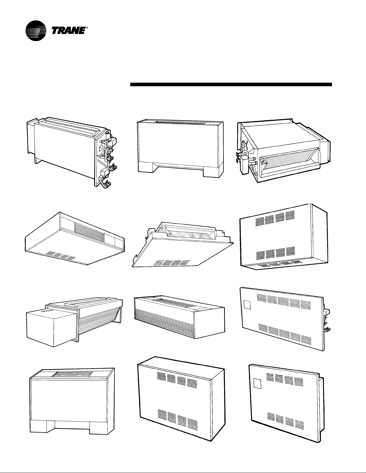
Available Models
model A vertical concealed
Installation
model B vertical cabinet
information
model C horizontal concealed
model D horizontal cabinet
model L low vertical concealed
model J slope-top cabinet
8 UNT-SVX07A-EN
model E horizontal recessed
model K low vertical cabinet
model M inverted vertical cabinet
(Force Flo only)
model F wall hung cabinet
model H
model N inverted vertical recessed
(Force Flo only)
vertical recessed
Page 9
general
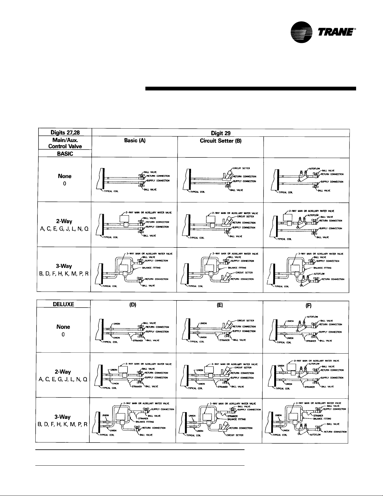
Factory-Installed Piping Packages
Installation
information
Note: This figure shows piping package components and basic arrangement. It is not
an accurate pictorial of what factory-installed piping packages look like.
UNT-SVX07A-EN 9
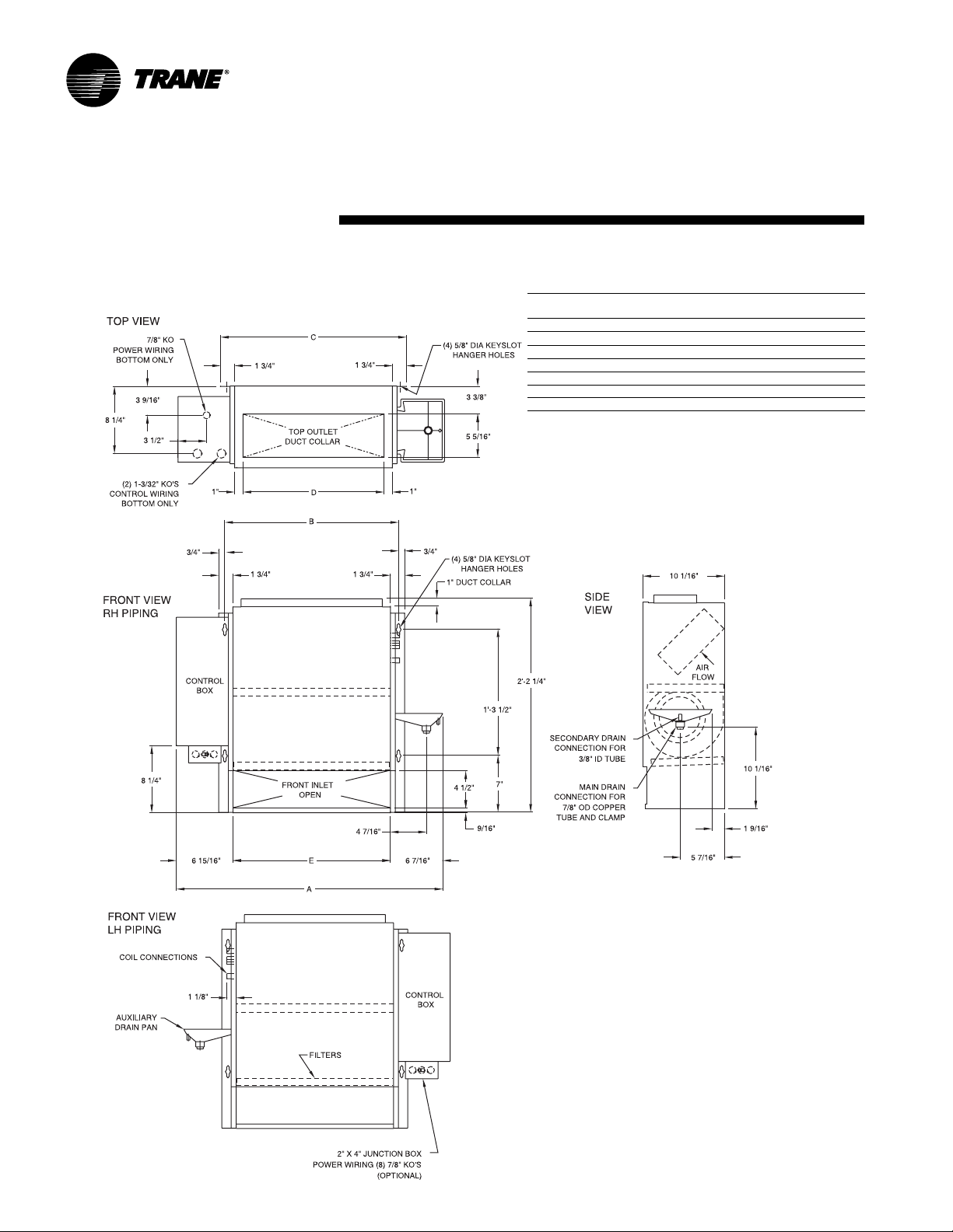
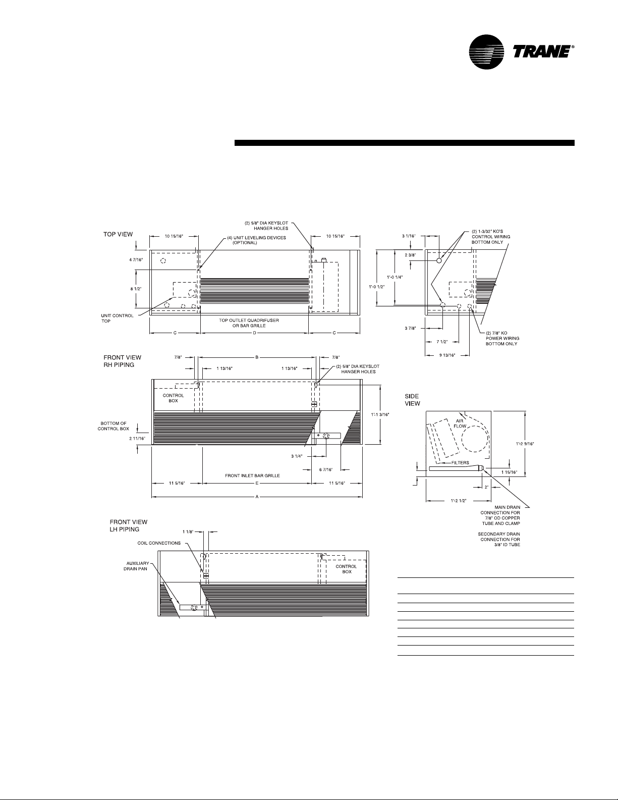
Page 10
dimensions
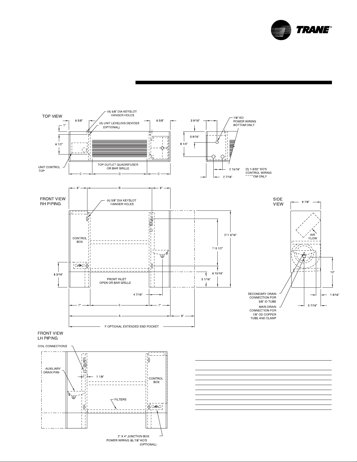
V ertical Concealed, Model A
Installation
& weights
Vertical Concealed Unit Dimensions & weights, in-lbs.
Unit
Size 02-03 04 06 08 10-12
A 2’-8 11/16” 3’-1 11/16” 3’-11 3/16” 4’-7 11/16” 6’-2 11/16”
B 1’-9 5/16” 2’-2 5/16” 2’-11 13/16” 3’-8 5/16” 5’-3 5/16”
C 1’-10 13/16” 2’-3 13/16” 3’-1 5/16” 3’-9 13/16” 5’-4 13/16”
D 1’-5 5/16” 1’-10 5/16” 2’-7 13/16” 3’-4 5/16” 4’-11 5/16”
E 1’-7 5/16” 2’-0 5/16” 2’-9 13/16” 3’-6 5/16” 5’-1 5/16”
operating weight 81 109 139 147 200
shipping weight 68 96 123 131 182
Notes:
1. Coil connections are always on the drain pan side and opposite the control
box.
2. Coil connections are 5/8” O.D. sweat. See pages 21-22 for locations.
3. All duct collar dimensions are to the outside of the collar.
4. See fresh air opening dimensions on pages 23-24.
10 UNT-SVX07A-EN
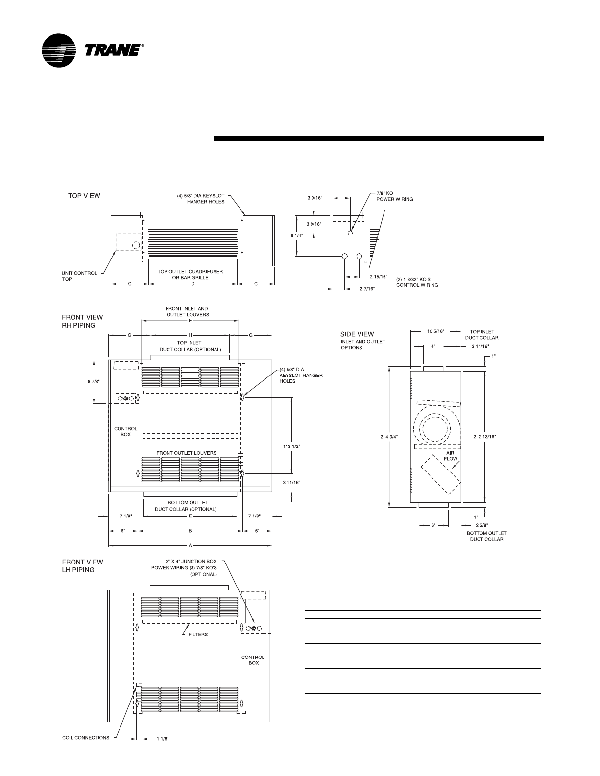
Page 11
dimensions
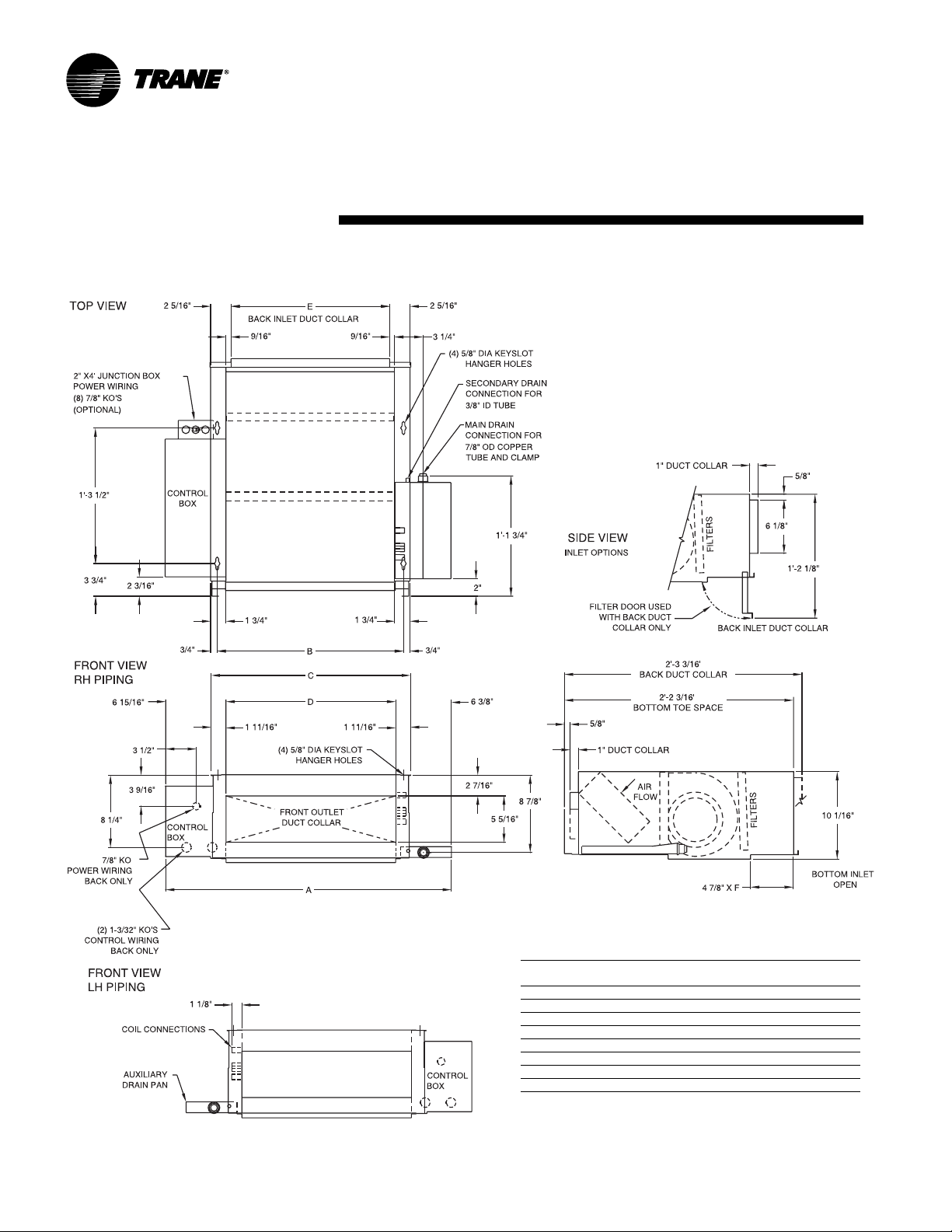
V ertical Cabinet, Model B
Installation
& weights
Vertical Cabinet Unit Dimensions, in-lbs.
unit
size 02-03 04 06 08 10-12
A 2’-9 5/16” 3’-2 5/16” 3’-11 3/16” 4’-8 5/16” 6’-3 5/16”
B 1’-9 5/16” 2’-2 5/16” 2’-11 3/16” 3’-8 5/16” 5’-3 5/16”
C7
D 1’-6” 2’-0” 2’-6” 3’-6” 5’-0”
E 1’-7 5/16” 2’-0 5/16” 2’-9 13/16” 3’-6 5/16” 5’-1 5/16”
F 3’-5 5/16” 3’-10 5/16” 4’-7 3/16” 5’-4 5/16” 6’-11 5/16”
operating weight 97 125 155 16 4 218
shipping weight 84 112 139 148 20 0
Notes:
1. Coil connections are always on the drain pan side and opposite the control box.
2. Coil connections are 5/8” O.D. sweat. See pages 21-22 for locations.
3. All duct collar dimensions are to the outside of the collar.
4. See pages 23-24 for fresh air opening dimensions.
UNT-SVX07A-EN 11
5
/8”7 1/8”8 7/8”7 1/8”7 5/8”
Page 12
dimensions
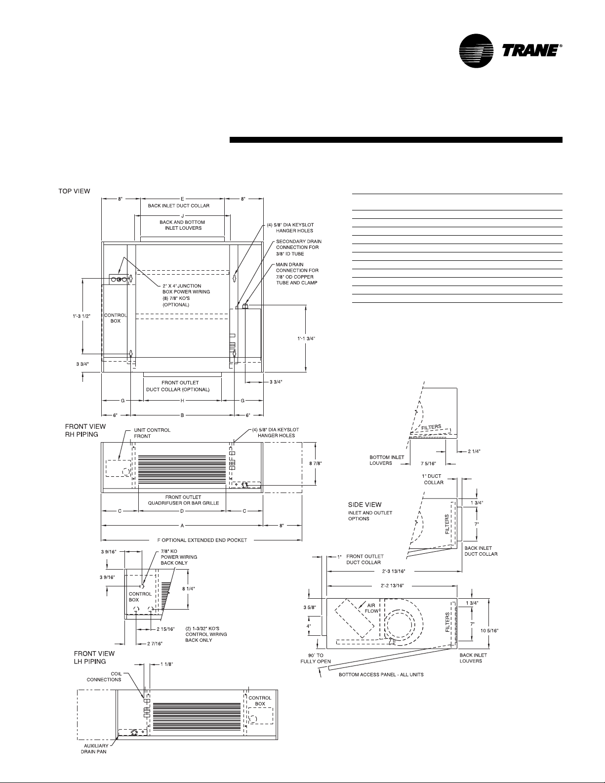
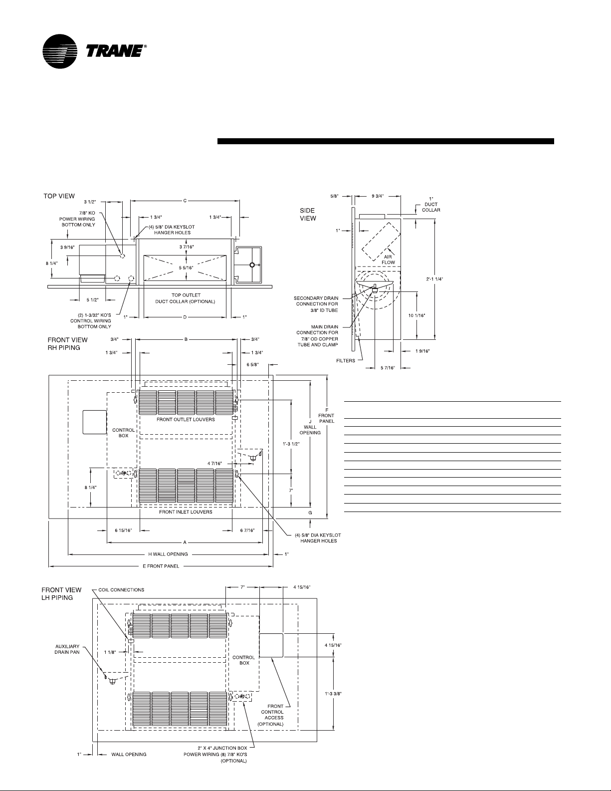
Horizontal Concealed, Model C
Installation
& weights
Horizontal Concealed Unit Dimensions, in-lbs.
unit
size 02-03 04 06 08 10-12
A 2’-8 11/16” 3’-1 11/16” 3’-11 3/16” 4’-7 11/16” 6’-2 11/16”
B 1’-9 5/16” 2’-2 5/16” 2’-11 13/16” 3’-8 5/16” 5’-3 5/16”
C 1’-10 13/16” 2’-3 13/16” 3’-1 5/16” 3’-9 13/16” 5’-4 13/16”
D 1’-7 3/8” 2’-0 3/8” 2’-9 7/8” 3’-6 3/8” 5’-1 3/8”
E 1’-6 1/8” 1’-11 1/8” 2’-8 5/8” 3’-5 1/8” 5’-0 1/8”
F 1’-7 5/16” 2’-0 5/16” 2’-9 13/16” 3’-6 5/16” 5’-1 5/16”
operating weight 81 109 139 147 20 0
shipping weight 68 96 123 13 1 18 2
Notes:
1. Coil connections are always on the drain pan side and opposite the control
box.
2. Coil connections are 5/8” O.D. sweat. See pages 21-22 for locations.
3. All duct collar dimensions are to the outside of the collar.
4. See pages 23-24 for fresh air opening dimensions.
12 UNT-SVX07A-EN
Page 13
dimensions
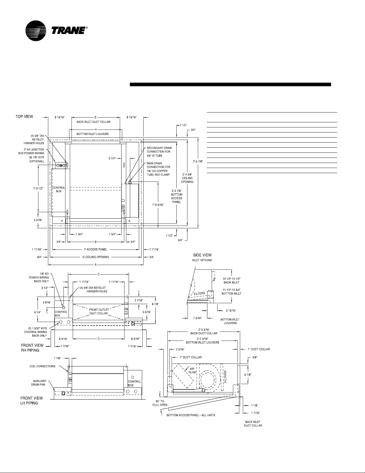
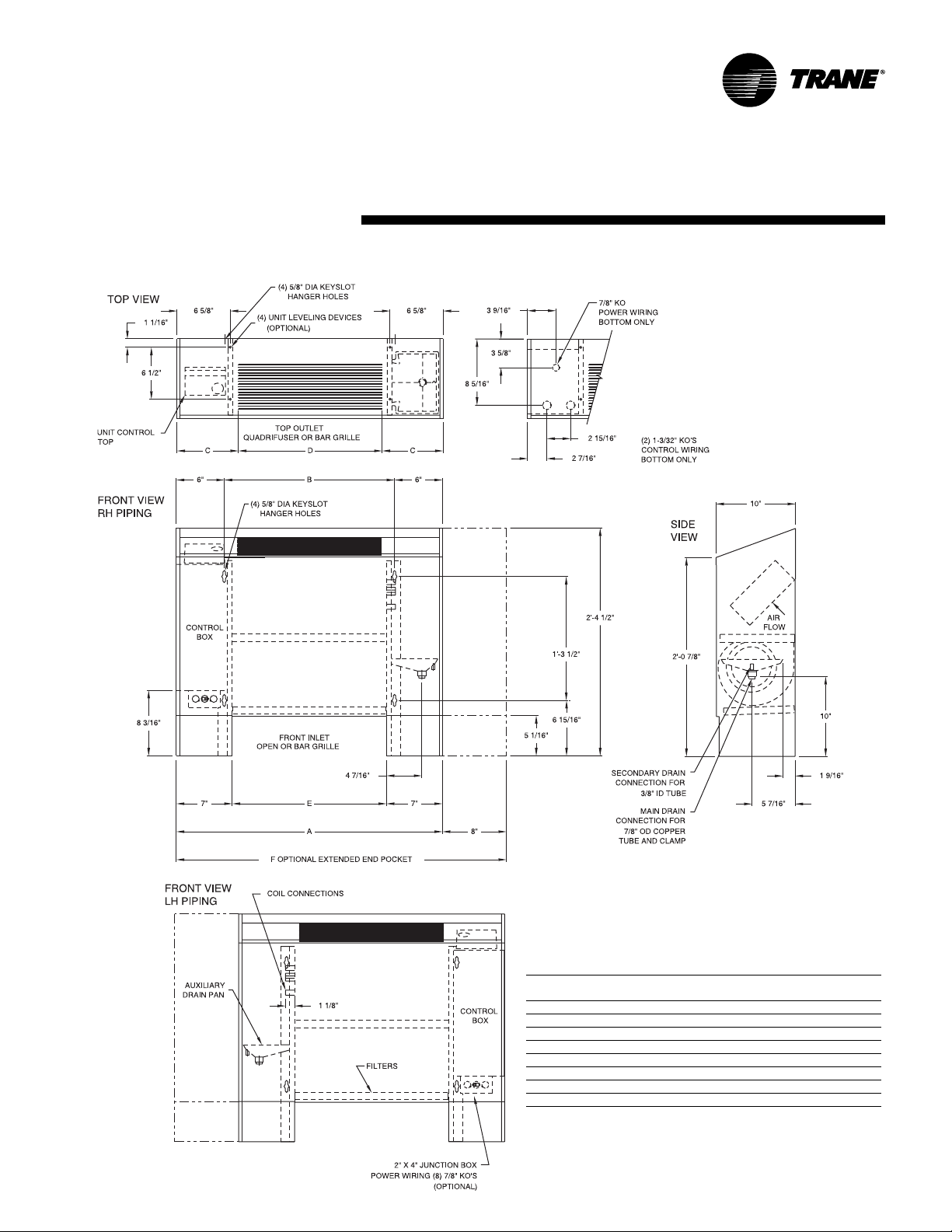
Horizontal Cabinet, Model D
Installation
& weights
Horizontal Cabinet Unit Dimensions, in-lbs.
unit
size 02-03 04 06 08 10-12
A 2’-9 5/16” 3’-2 5/16” 3’-11 3/16” 4’-8 5/16” 6’-3 5/16”
B 1’-9 5/16” 2’-2 5/16” 2’-11 13/16” 3’-8 5/16” 5’-3 5/16”
C7
D 1’-6” 2’-0” 2’-6” 3’-6” 5’-0”
E 1’-5 1/4” 1’-10 1/4” 2’-7 3/4” 3’-4 1/4” 4’-11 1/4”
F 3’-5 5/16” 3’-10 5/16” 4’-7 3/16” 5’-4 5/16” 6’-11 5/16”
G8
H 1’ -4” 1’-10” 2’-4” 3’-4” 4’-10”
J 1’-7 3/4” 1’-11 3/4” 2’-7 3/4” 3’-3 3/4” 4’-11 3/4”
operating weight 97 125 155 164 218
shipping weight 84 112 139 148 20 0
Notes:
1. Coil connections are always on the drain pan side and opposite the control
box.
2. Coil connections are 5/8” O.D. sweat. See pages 21-22 for locations.
3. All duct collar dimensions are to the outside of the collar.
4. See pages 23-24 for fresh air opening dimensions.
5
/8”7
5
/8”8
1
/8”8 7/8”7 1/8”7 5/8”
1
/8”9 7/8”8 1/8”8 5/8”
UNT-SVX07A-EN 13
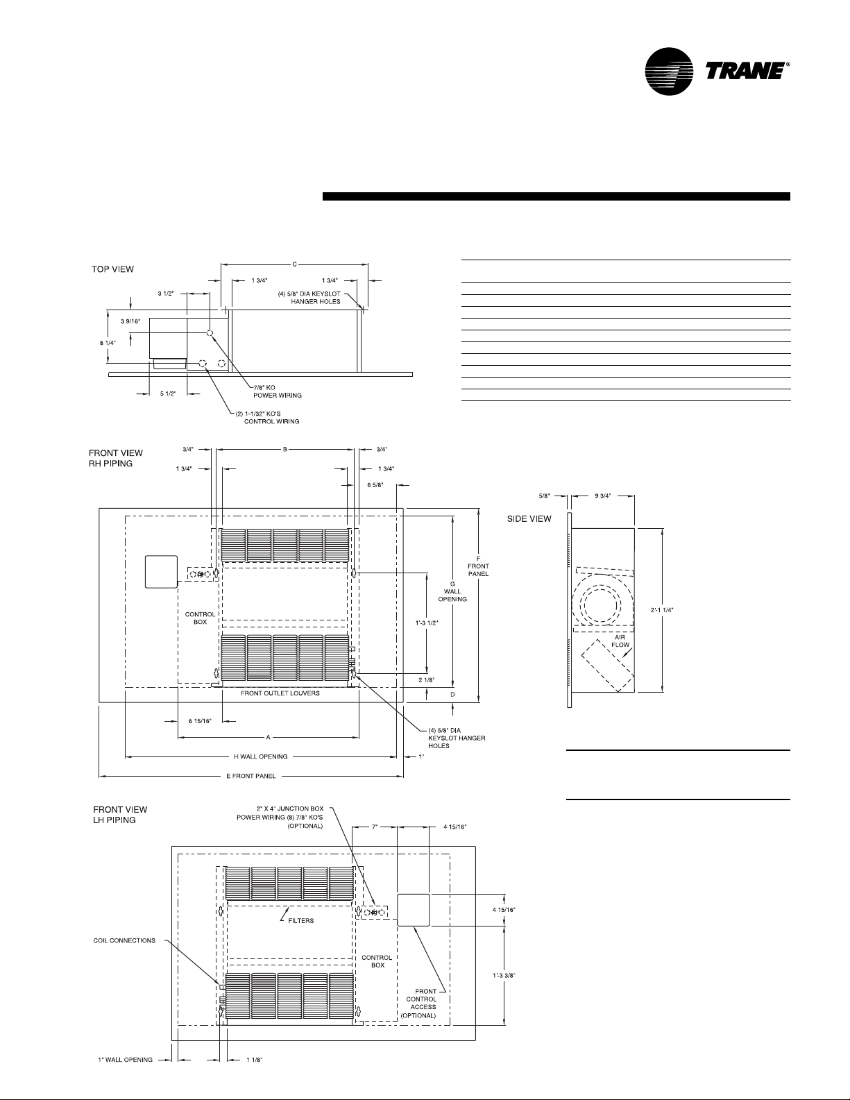
Page 14
dimensions
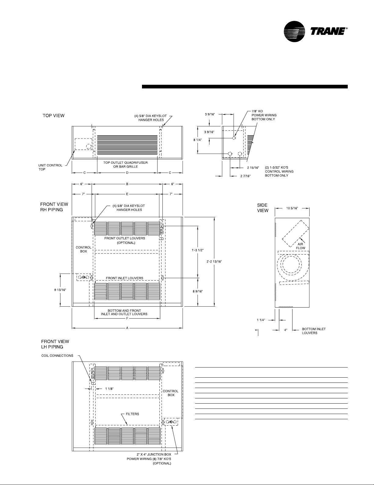
Horizontal Recessed, Model E
Installation
& weights
Horizontal Recessed Unit Dimensions, in-lbs.
unit
size 02-03 04 06 08 10-12
A 2’-11 13/16” 3’-4 13/16” 4’-2 5/16” 4’-10 13/16” 6’-5 13/16”
B 1’-9 5/16” 2’-2 5/16” 2’-11 13/16” 3’-8 5/16” 5’-3 5/16”
C 1’-10 13/16” 2’-3 13/16” 3’-1 5/16” 3’-9 13/16” 5’-4 13/16”
D 1’-7 3/8” 2’-0 3/8” 2’-9 7/8” 3’-6 3/8” 5’-1 3/8”
E 1’-6 1/8” 1’-11 1/8” 2’-8 5/8” 3’-5 1/8” 5’-0 1/8”
F 2’-8 7/16” 3’-1 7/16” 3’-10 15/16” 4’-7 7/16” 6’-2 7/16”
G 2’-10 5/16” 3’-3 5/16” 4’-0 13/16” 4’-9 5/16” 6’-4 5/16”
H 1’-7 3/4” 1’-11 3/4” 2’-7 3/4” 3’-3 3/4” 4’-11 3/4”
operating weight 78 88 128 139 253
shipping weight 68 78 118 12 9 24 3
Notes:
1. Coil connections are always on the drain pan side and opposite the control
box.
2. Coil connections are 5/8” O.D. sweat. See pages 21-22 for locations.
3. All duct collar dimensions are to the outside of the collar.
4. See pages 23-24 for fresh air opening dimensions.
14 UNT-SVX07A-EN
Page 15
dimensions
V ertical Wall Hung Cabinet, Model F
Installation
& weights
Vertical wall hung cabinet unit dimensions & weights, in-lbs.
unit
size 02-03 04 06 08 10-12
A 2’-9 5/16” 3’-2 5/16” 3’-11 13/16” 4’-8 5/16” 6’-3 5/16”
B 1’-9 5/16” 2’-2 5/16” 2’-11 13/16” 3’-8 5/16” 5’-3 5/16”
C7
D 1’-6” 2’-0” 2’-6” 3’-6” 5’-0”
E 1’-7 5/16” 2’-0 5/16” 2’-9 13/16” 3’-6 5/16” 5’-1 5/16”
F 1’-7 3/4” 1’-11 3/4” 2’-7 3/4” 3’-3 3/4” 4’-11 3/4”
operating weight 97 125 155 164 218
shipping weight 84 1 12 139 148 20 0
Notes:
1. Coil connections are always on the side opposite the control box.
2. Coil connections are 5/8” O.D. sweat. See pages 21-22 for locations.
3. All duct collar dimensions are to the outside of the collar.
4. See pages 23-24 for fresh air opening dimensions.
UNT-SVX07A-EN 15
5
/8”7 1/8”8 7/8”7 1/8”7 5/8”
Page 16
dimensions
V ertical Recessed, Model H
Installation
& weights
Vertical Recessed Unit Dimensions, in-lbs.
unit
size 02-03 04 06 08 10-12
A 2’-8 11/16” 3’-1 11/16” 3’-11 3/16” 4’-7 11/16” 6’-2 11/16”
B 1’-9 5/16” 2’-2 5/16” 2’-11 13/16” 3’-8 5/16” 5’-3 5/16”
C 1’-10 13/16” 2’-3 13/16” 3’-1 5/16” 3’-9 13/16” 5’-4 13/16”
D 1’-5 5/16” 1’-10 5/16” 2’-7 13/16” 3’-4 5/16” 4’-11 5/16”
E 3’-11” 4’-3” 5’-3” 5’-5 1/2” 7’-5 1/2”
F 2’-6” 2’-6” 2’-6” 2’-9 1/2” 2’-9 1/2”
G2
H 3’-6” 4’-0” 4’-9” 5’-3” 7’-3”
J 2’-2 1/2” 2’-2 1/2” 2’-2 1/2” 2’-3 1/2” 2’-3 1/2”
operating weight 78 88 128 13 9 253
shipping weight 68 78 118 129 243
Notes:
1. Coil connections are always on the drain pan side and opposite the control
box.
2. Coil connections are 5/8” O.D. sweat. See pages 21-22 for locations.
3. All duct collar dimensions are to the outside of the collar.
4. See pages 23-24 for fresh air opening dimensions.
5. Dimension 'G' refers to the required minimum distance between the finished
floor, and the bottom of the unit.
3
/8”2 3/8”2 3/8”4 1/8”4 1/8”
16 UNT-SVX07A-EN
Page 17
dimensions
V ertical Slope Top, Model J
Installation
& weights
Vertical Slope Top Unit Dimensions, in-lbs.
unit
size 02-03 04 06 08 10-12
A 2’-9 5/16” 3’-2 5/16” 3’-11 13/16” 4’-8 5/16” 6’-3 5/16”
B 1’-9 5/16” 2’-2 5/16” 2’-11 13/16” 3’-8 5/16” 5’-3 5/16”
C7
D 1’-6” 2’-0” 2’-6” 3’-6” 5’-0”
E 1’-7 5/16” 2’-0 5/16” 2’-9 13/16” 3’-6 5/16” 5’-1 5/16”
F 3’-5 5/16” 3’-10 5/16” 4’-7 13/16” 5’-4 5/16” 6’-11 5/16”
operating weight 97 125 155 164 218
shipping weight 84 112 139 148 200
Notes:
1. Coil connections are always on the drain pan side and opposite the control box.
2. Coil connections are 5/8” O.D. sweat. See pages 21-22 for locations.
3. All duct collar dimensions are to the outside of the collar.
4. See pages 23-24 for fresh air opening dimensions.
UNT-SVX07A-EN 17
5
/8”7 1/8”8 7/8”7
1
/8”7
5
/8”
Page 18
dimensions
Low V ertical Concealed, Model K
Installation
& weights
Low Vertical Concealed Unit Dimensions, in-lbs.
unit size 03 04 06
A 3’-5 7/16” 4’-2 15/16” 4’-11 7/16”
B 2’-2 1/4” 2’-11 3/4” 3’-8 1/4”
C 2’-3 15/16” 3’-0 13/16” 3’-9 15/16”
D 1’-10 5/16” 2’-7 13/16” 3’-4 5/16”
E 2’-0 1/4” 2’-9 3/4” 3’-6 1/4”
operating weight 109 139 147
shipping weight 96 123 131
Notes:
1. Coil connections are always on the drain pan side and opposite
the control box.
2. Coil connections are 5/8” O.D. sweat.
3. All duct collar dimensions are to the outside of the collar.
4. See pages 23-24 for fresh air opening dimensions.
18 UNT-SVX07A-EN
Page 19
dimensions
Low V ertical Cabinet, Model L
Installation
& weights
Low Vertical Cabinet Unit Dimensions, in-lbs.
unit
size 03 04 06
A 3’-10 15/16” 4’-8 7/16” 5’-4 15/16”
B 2’-2 1/4” 2’-11 3/4” 3’-8 1/4”
C 11 7/16” 1’-1 5/16” 11 7/16”
D 2’-0” 2’-6” 3’-6”
E 2’-0 1/4” 2’-9 3/4” 3’-6 1/4”
operating weight 125 155 164
shipping weight 112 139 148
Notes:
1. Coil connections are always on the drain pan side and
opposite the control box.
2. Coil connections are 5/8” O.D. sweat.
3. All duct collar dimensions are to the outside of the collar.
4. See pages 23-24 for fresh air opening dimensions.
UNT-SVX07A-EN 19
Page 20
dimensions
Inverted V ertical Cabinet, Model M
Installation
& weights
Inverted vertical cabinet unit dimensions & weights, in-lbs.
unit
size 02-03 04 06 08 10-12
A 2’-9 5/16” 3’-2 5/16” 3’-11 13/16” 4’-8 5/16” 6’-3 5/16”
B 1’-9 5/16” 2’-2 5/16” 2’-11 13/16” 3’-8 5/16” 5’-3 5/16”
C7
D 1’-6” 2’-0” 2’-6” 3’-6” 5’-0”
E 1’-7” 2’-0” 2’-9 1/2” 3’-6” 5’-1”
F 1’-7 3/4” 1’-11 3/4” 2’-7 3/4” 3’-3 3/4” 4’-11 3/4”
G8
H 1’-4” 1’-10” 2’-4” 3’-4” 4’-10”
operating weight 97 1 25 1 55 164 218
shipping weight 84 112 139 148 200
Notes:
1. Coil connections are always on the side opposite the control box.
2. Coil connections are 5/8” O.D. sweat. See pages 21-22 for locations.
3. All duct collar dimensions are to the outside of the collar.
4. See pages 23-24 for fresh air opening dimensions.
5
/8”7
5
/8”8
1
/8”8
1
/8”9
7
/8”7
7
/8”8
1
/8”7 5/8”
1
/8”8 5/8”
20 UNT-SVX07A-EN
Page 21
dimensions
Inverted V ertical Recessed, Model N
Installation
Inverted vertical recessed unit dimensions & weights, in-lbs.
unit
size 02-03 04 06 08 10-12
operating weight 78 88 128 139 253
shipping weight 68 78 118 129 243
Notes:
1. Coil connections are always on the side opposite the control box.
2. Coil connections are 5/8” O.D. sweat. See pages 21-22 for locations.
3. All duct collar dimensions are to the outside of the collar.
4. See pages 23-24 for fresh air opening dimensions.
& weights
A 2’-3 7/8” 2’-8 7/8” 3’-6 3/8” 4’-2 7/8” 5’-9 7/8”
B 1’-9 5/16” 2’-2 5/16” 2’-11 13/16” 3’-8 5/16” 5’-3 5/16”
C 1’-10 13/16” 2’-3 13/16” 3’-1 5/16” 3’-9 13/16” 5’-4 13/16”
D2
E 3’-11” 4’-3” 5’-3” 5’-5 1/2” 7’-5 1/2”
F 2’-6” 2’-6” 2’-6” 2’-9 1/2” 2’-9 1/2”
G 2’-2 1/2” 2’-2 1/2” 2’-2 1/2” 2’-3 1/2” 2’-3 1/2”
H 3’-6” 4’-0” 4’-9” 5’-3” 7’-3”
3
/8”2
3
/8”2 3/8”4 1/8”4 1/8”
Dimension 'D' refers to the required
minimum distance between the finished
floor, and the bottom of the unit.
UNT-SVX07A-EN 21
Page 22
dimensions
Fan-Coil
Coil Connections
V ertical Units
Installation
& weights
Fan-Coil
Coil Connections
Horizontal Units
22 UNT-SVX07A-EN
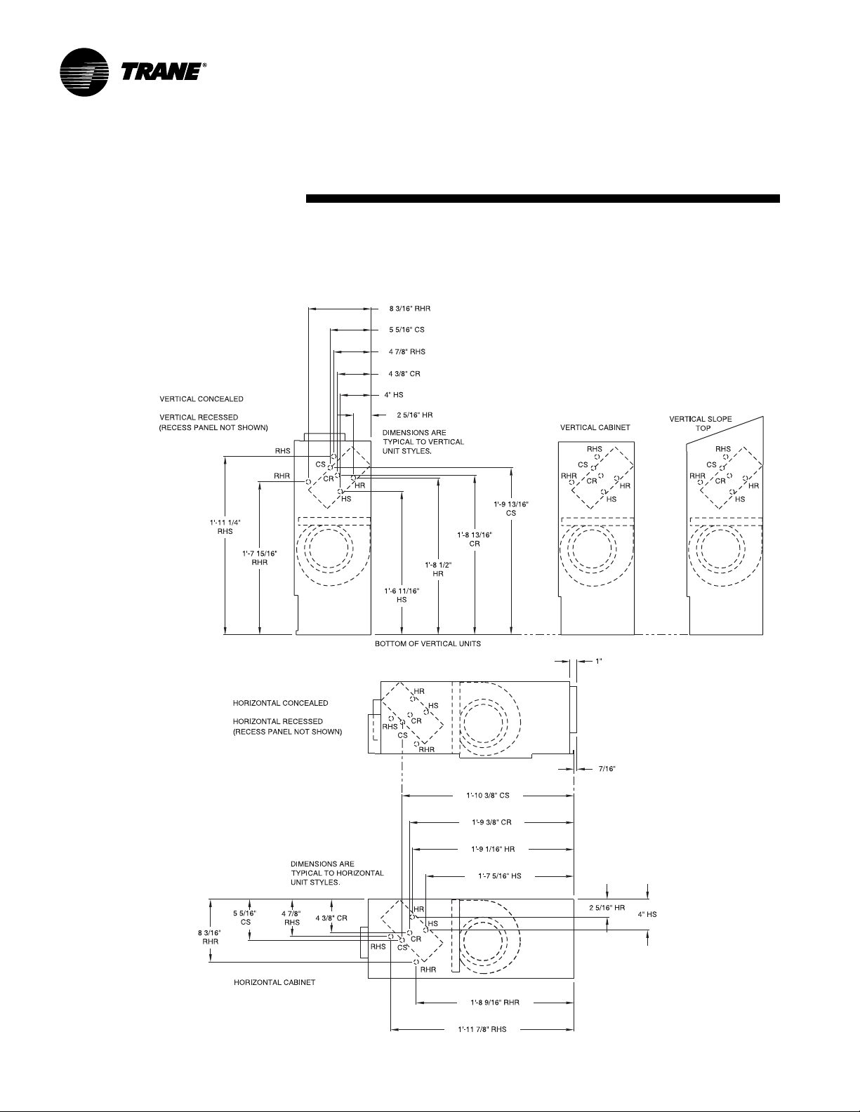
Page 23
dimensions
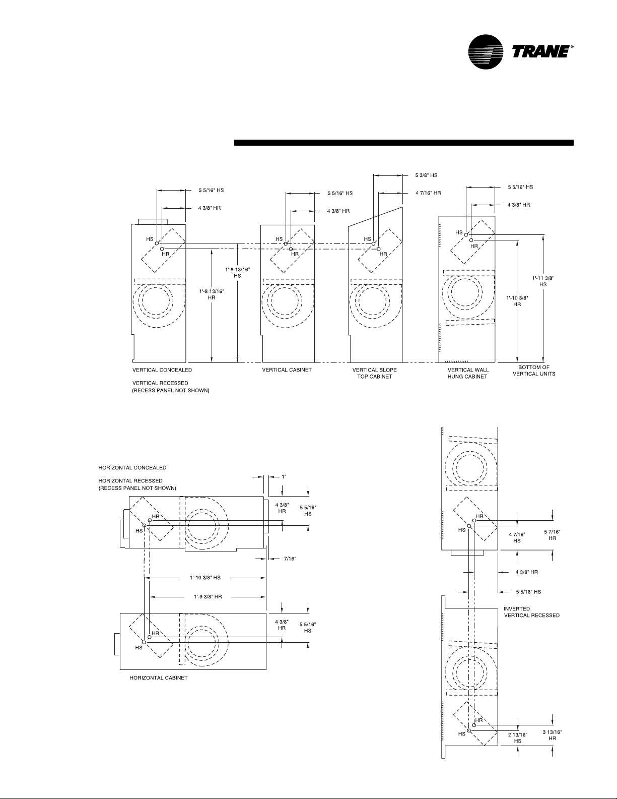
Force Flo
Coil Connections,
V ertical Units
Installation
& weights
Force Flo
Coil Connections,
Horizontal Units
HR - Hot Water Return
HS - Hot Water Supply
Force Flo
Coil Connections,
Inverted Units
UNT-SVX07A-EN 23
Page 24
dimensions
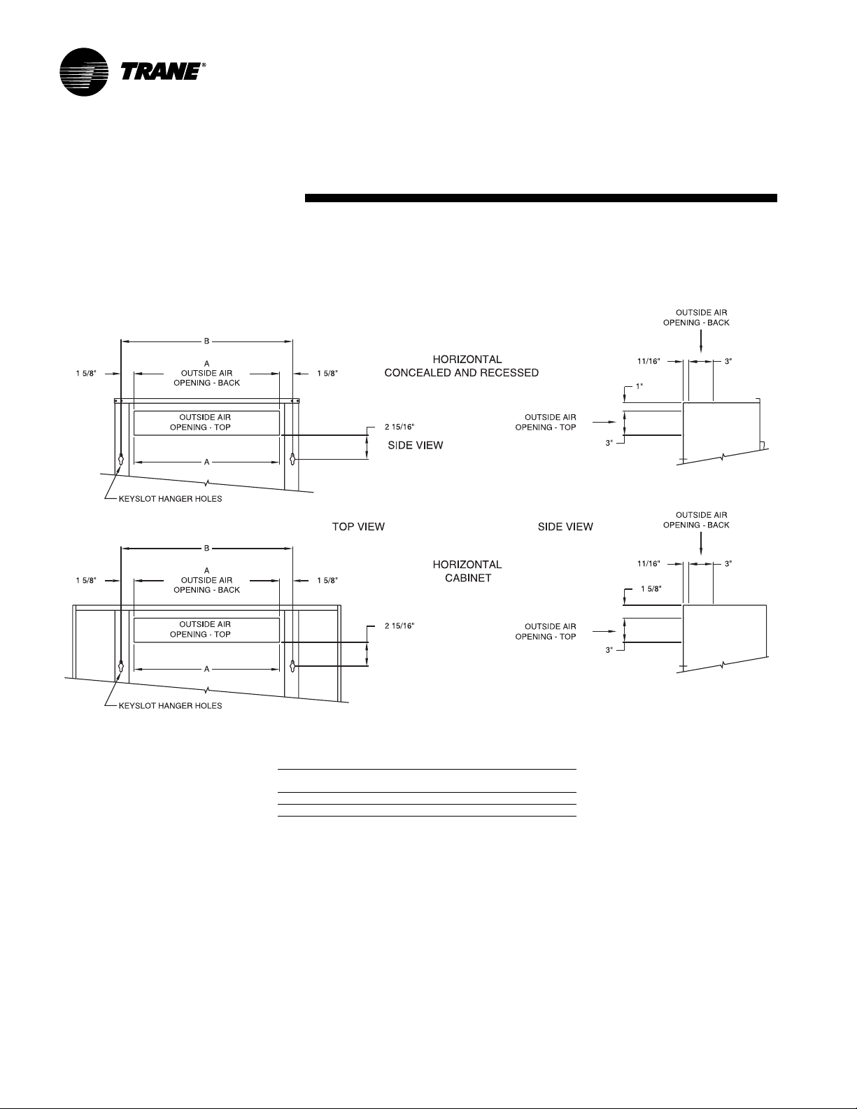
Fresh Air Opening Locations
Horizontal Units Models C, D, and E
Installation
& weights
Fresh Air Opening Dimensions, Horizontal Units
Unit
Size 02-03 04 06 08 10-12
A 1’-6” 1’-11” 2’-8 1/2” 3’-5” 5’-0”
B 1’-9 5/16” 2’-2 5/16” 2’-11 13/16” 3’-8 5/16” 5’-3 5/16”
24 UNT-SVX07A-EN
Page 25

dimensions
Fresh Air Opening Locations
V ertical Units Models A, B, F, & J
Installation
& weights
WALL HUNG
Fresh Air Opening Dimensions, Vertical Units
Unit
Size 02-03 04 06 08 10-12
A 1’-6” 1’-11” 2’-8 1/2” 3’-5” 5’-0”
B 1’-9 5/16” 2’-2 5/16” 2’-11 13/16” 3’-8 5/16” 5’-3 5/16”
UNT-SVX07A-EN 25
Page 26

dimensions
Wall Box
Wall Box Dimensions
Unit Size Dimensions Internal
Ref. Only A x B Supports
02 - 03 24 3/8 x 4 3/
04 24 3/8 x 7 1/
06 33 1/8 x 7 1/
08 37 1/2 x 7 1/
10 -12 58 1/4 x 7 1/
4
2
2
2
2
Installation
& weights
CONTINUOUS
MORTAR RIBS
TOP AND
BOTTOM
1
1
2
3
4
1
”
/
8
1
”
/
2
1
”
/
8
1
”
/
2
3
”
/
4
”
1 3/
8
CLEARANCE
FOR DRAINAGE
1
”
/
8
”
4
WOVEN ALUMINUM
INSECT SCREEN
5
CONTINUOUS DRIP LIP
TOP AND BOTTOM
26 UNT-SVX07A-EN
SUPPORTS EQUALLY SPACED.
NOT TO EXCEED 12” O.C.
ADDITIONAL INTERNAL
”
/
8
Page 27

dimensions
Installation
Projection Panel
Projection Panel Dimensions
Unit
Size 02 - 03 04 06 08 10 - 12
A 3’-11” 4’-3” 5’-3” 5’-5 1/2” 7’-5 1/2”
B 2’-6” 2’-6” 2’-6” 2’-9 1/2” 2’-9 1/2”
Projection Panel, All Unit Sizes
C2”2 1/2”3” 3 1/2”4” 4 1/2”5” 5 1/2”6”
D1 1/8“1 5/8“2 1/8“2 5/8“3 1/8“3 5/8“4 1/8“4 5/8“5 1/8“
E8 5/8“8 1/8“7 5/8“7 1/8“6 5/8“6 1/8“5 5/8“5 1/8“4 5/8“
& weights
UNIT TO WALL — TOP VIEW
FRONT VIEW ISO
REAR VIEW ISO
UNT-SVX07A-EN 27
Page 28

pre-installation
WARNING
Hazardous Voltage w/Capacitors!
Disconnect all electric power , including
remote disconnects and discharge all
motor start/run capacitors before
servicing. Follow proper lockout/
tagout procedures to ensure the
power cannot be inadvertently
energized. For variable frequency
drives or other energy storing
components provided by T rane or
others, refer to the appropriate
manufacturer’ s literature for allowable
waiting periods for discharge of
capacitors. V erify with an appropriate
voltmeter that all capacitors have
discharged. Failure to disconnect
power and discharge capacitors
before servicing could result in death
or serious injury.
Receiving and Handling
Upon delivery, inspect all components for
possible shipping damage. See the
Receiving Checklist section for detailed
instructions. T rane recommends leaving
units and accessories in their shipping
packages/skids for protection and ease of
handling until installation.
Shipping Package
UniT rane fan-coil and Force Flo cabinet
heaters ship in individual cartons for
handling and storage ease. Each carton
has tagging information such as the
model number, sales order number, serial
number , unit size, piping connections, and
unit style to help properly locate the unit
in the floor plan. If specified, the unit will
ship with tagging designated by the
customer .
Receiving Checklist
Complete the following checklist
immediately after receiving unit shipment
to detect possible shipping damage.
!! Inspect individual cartons before
accepting. Check for rattles, bent carton
corners, or other visible indications of
shipping damage.
Installation
If a unit appears damaged, inspect it
!
immediately before accepting the
shipment. Manually rotate the fan
wheel to ensure it turns freely. Make
specific notations concerning the
damage on the freight bill. Do not
refuse delivery.
Inspect the unit for concealed damage
!
before it is stored and as soon as
possible after delivery. Report
concealed damage to the freight line
within the allotted time after delivery.
Check with the carrier for their allotted
time to submit a claim.
Do not move damaged material from
!
the receiving location. It is the receiver’s
responsibility to provide reasonable
evidence that concealed damage did
not occur after delivery.
Do not continue unpacking the
!
shipment if it appears damaged. Retain
all internal packing, cartons, and crate.
T ake photos of damaged material.
Notify the carrier’s terminal of the
!
damage immediately by phone and
mail. Request an immediate joint
inspection of the damage by the carrier
and consignee.
Notify your Trane representative of
!
the damage and arrange for repair.
Have the carrier inspect the damage
before making any repairs to the unit.
Compare the electrical data on the unit
!
nameplate with the ordering and
shipping information to verify the
correct unit is received.
Jobsite Storage
This unit is intended for indoor use only.
Store the unit indoors to protect the unit
from damage due to the elements. If
indoor storage is not possible, make the
following provisions for outdoor storage:
1. Place the unit(s) on a dry surface or
raised off the ground to assure
adequate air circulation beneath unit
and to assure that no portion of the unit
contacts standing water at any time.
2. Cover the entire unit with a
tarp only . Do not use clear, black or
plastic tarps as they may cause
excessive moisture condensation and
equipment damage.
canvas
considerations
Installation Preparation
Before installing the unit, consider the
following unit location recommendations
to ensure proper unit operation.
1. Clearances: Allow adequate service
and code clearances as recommended
in “Service Access” section. Position
the unit and skid assembly in its final
location.
2. Structural support: Ensure the
structural support is strong enough to
adequately support the unit. The
installer is responsible for supply
support rods for installation of ceiling
units.
3. Level: Verify the floor or foundation is
level. Shim or repair as necessary. To
ensure proper unit operation, install the
unit level (zero tolerance) in both
horizontal axes. Failure to level the unit
properly can result in condensate
management problems, such as
standing water inside the unit.
4. Condensate line & piping: Consider coil
piping and condensate drain
requirements. Verify condensate line is
continuously pitched 1 inch per 10 feet
of condensate line run to adequately
drain condensate.
5. Wall & ceiling openings: V ertical
recessed/concealed units require wall/
ceiling openings. Refer to submittal for
specific dimensions before attempting
to install. Horizontal recessed/concealed
units must meet the requirements of
the National Fire Protection Association
(NFPA) Standard 90A or 90B
concerning the use of concealed ceiling
spaces as return air plenums. Refer to
the submittal for specific dimensions of
ceiling openings.
6. Exterior: T ouch up painted panels if
necessary. If panels need paint, sanding
is not necessary. However, clean the
surface of any oil, grease, or dirt
residue so the paint will adhere.
Purchase factory approved touch up
epoxy paint from your local T rane
Service Parts Center and apply.
28 UNT-SVX07A-EN
Page 29

Service Access
Service access is available from the front
on vertical units and from the bottom on
horizontal units. Cabinet and recessed
units have removable front or bottom
panels to allow access into the unit. See
Figure I-PC-1 for recommended service
and operating clearances.
Units have either right or left hand piping.
Reference piping locations by facing the
front of the unit (airflow discharges from
the front). The control panel is always on
the end opposite the piping.
The fan board assembly and main drain
pan are easily removable for cleaning.
See the“Maintenance” section for more
details on servicing.
24"
model B, vertical cabinet
model L, low vertical cabinet
12"
both sides
3"
pre-installation
considerationsInstallation
model A, vertical concealed
model K, low vertical concealed
model H, vertical recessed
8.5"
both sides
36"
Pre-Installation Checklist
Complete the following checklist before
beginning unit installation.
!
V erify the unit size and tagging with the
unit nameplate.
Make certain the floor or foundation is
!
level, solid, and sufficient to support the
unit and accessory weights. See the
Dimensions and Weights section. Level
or repair the floor before positioning the
unit if necessary.
Allow minimum recommended
!
clearances for routine maintenance and
service. Refer to unit submittals for
dimensions.
Allow one and one half fan diameters
!
above the unit before the discharge
ductwork makes any turns.
12"
both sides
24"
front discharge
28"
model D, horizontal cabinet
Figure I-PC-1. Recommended service clearances
8.5"
both sides
model C, horizontal concealed
model E, horizontal recessed
28"
UNT-SVX07A-EN 29
Page 30

mechanical
requirementsInstallation
Duct Connections
Install all air ducts according to National
Fire Protection Association standards for
the Installation of Air Conditioning and
Ventilating Systems (NFPA 90A and 90B).
Install all air ducts according to the
National Fire Protection Association
standards for the “Installation of Air
Conditioning and Ventilation Systems
other than Residence Type (NFPA 90A)
and Residence T ype Warm Air Heating
and Air Conditioning Systems (NFPA
90B).
WARNING
Voltage w/Capacitors!
all electric power, including remote
disconnects and discharge all motor
start/run capacitors before servicing.
Follow proper lockout/tagout
procedures to ensure the power
cannot be inadvertently energized.
For variable frequency drives or other
energy storing components provided
by T rane or others, refer to the
appropriate manufacturer’s literature
for allowable waiting periods for
discharge of capacitors. Verify with an
appropriate voltmeter that all
capacitors have discharged. Failure to
disconnect power and discharge
capacitors before servicing could
result in death or serious injury.
The unit’s airflow configuration varies
dependent on the model and options
ordered. A one-inch duct collar is
provided on units with a ducted return
and/or discharge to attach ductwork to
the unit.
T rane recommends using galvanized
sheet metal ductwork with fan-coil and
cabinet heater units. Slide the sheetmetal
duct over the duct collar flange of the unit,
seal the joint and fasten with sheetmetal
screws.
Hazardous
Disconnect
Note: Do not run screws through the
removable front panel on concealed
units.
Ductwork Recommendations
Follow the general recommendations
listed below when installing
ductwork for the unit.
1. Discharge ductwork should run in a
straight line, unchanged in size or
direction, for a minimum equivalent
distance of three fan diameters from
the unit (approximately 20 inches).
2. When making duct turns and
transitions avoid sharp turns and use
proportional splits, turning vanes, and
air scoops when necessary.
3. When possible, construct, and orient
supply ductwork turns in the same
direction as the fan rotation.
Piping Considerations
Hydronic Coil Piping
Before installing field piping to the coil,
consider the following .
• All coil connections are
1
/2-inch nominal) female copper
connections.
• The supply and return piping should not
interfere with the auxiliary drain pan or
condensate line. See “Connecting the
Condensate Drain” section for more
detailed information.
• The installer must provide adequate
piping system filtration and water
treatment.
• Exterior condensate may be an issue
(fan-coils only) if field piping does not
have a control valve. Refer to the
supply and return header locations in
the “Dimensions and Weights” section.
Note: When using a field supplied piping
package in a fan-coil unit, allow sufficient
room to install the auxiliary drain pan. In
addition, piping package must not extend
over edges of auxiliary drain pan.
5
/8-inch O.D. (or
Connecting field piping to coil
1. Remove the auxiliary drain pan, if it is
in place, to prevent exposureto
dripping solder or excessive
temperatures.
2. Slide a
coupling (installer provided) onto the
coil headers.
Note: For vertical fan-coil units, push the
main condensate drain hose and
overflow condensate drain hose through
the inside of the chassis end panel to
prevent them from getting burned when
making sweat connections. Be sure to
pull the hoses back through and route to
the auxiliary drain pan when the end
panel has cooled.
3. Solder the joint using bridgit lead-free
solder (ASTM B32-89) to provide a
watertight connection. Avoid
overheating factory soldered joints
when soldering field connections to the
coil to prevent leakage from occurring.
4. Insulate all piping to coil connections as
necessary after connections are
complete.
Note: Maintain a minimum distance of
one foot between the reduction fitting for
the
unit piping connections.
5. Install the optional auxiliary drain pan,
which ships in the accessory packet.
1
/2-inch sweat connection
1
/2-inch diameter line and the fan-coil
30 UNT-SVX07A-EN
Page 31
mechanical
requirementsInstallation
Water Piping Connections to FactoryInstalled Piping Package
Before installing water piping supply and
return lines to factory piping package,
note the following items.
• All piping connections are
(1/2-inch nominal) female copper
connections.
• The fan-coil supply and return piping
should not interfere with the auxiliary
drain pan or condensate line. See
“Connecting the Condensate Drain”
section for more information.
• The installer must provide adequate
piping system filtration and water
treatment.
• If the unit has a factory deluxe piping
package, the piping includes a strainer
with a 20-mesh size screen, which
allows minimal protection from debris.
Therefore, clean the strainer regularly.
Note: Maintain a minimum distance of
one foot between the reduction fitting for
1
/2-inch diameter line and the fan-coil
the
piping connections.
1. The factory piping package ships with
brackets to adequately support the
piping during shipment. Remove these
brackets before connecting water
piping to the unit.
2. Close the piping end valves to the fully
open position to prevent damage to the
valve seat during brazing.
3. Remove the auxiliary drain pan, if it is
in place, to prevent exposure to
dripping solder or excessive
temperatures.
4. Solder water piping connections to
supply and return end connections.
Avoid overheating factory soldered
joints to prevent the possibility of
leakage.
5. Insulate fan-coil piping to auxiliary
drain pan connections and any piping
that is not above the auxiliary drain pan.
Condensate Drain
1. De-burr the pipe end before making
the connection to the drain pan.
2. Connect a
tube, with a 0.20 inch wall thickness, to
the auxiliary drain pan. This should be a
mechanical connection that allows easy
removal of the auxiliary drain pan
when servicing the piping end pocket.
7
/8-inch O.D. copper pipe or
5
/8-inch O.D.
3. Slide the copper pipe over the drain
pan nipple and tighten the collar on the
pipe with a hose clamp (installer
supplied).
Maintain a continuous drain line pitch of
one inch per ten feet of drain line run to
provide adequate condensate drainage.
Extend the drain line straight from the
drain pan a minimum distance of six
inches before making any turns. The
installer must provide proper support for
the drain line to prevent undue stress on
the auxiliary drain pan.
Install a secondary overflow drain line if
necessary by punching out the overflow
drain nipple on the auxiliary drain pan.
Next, place a
flexible plastic tube over the nipple and
secure
Note: The installer is responsible for
adequately insulating field piping. See the
“External Insulating Requirements
section for more information.
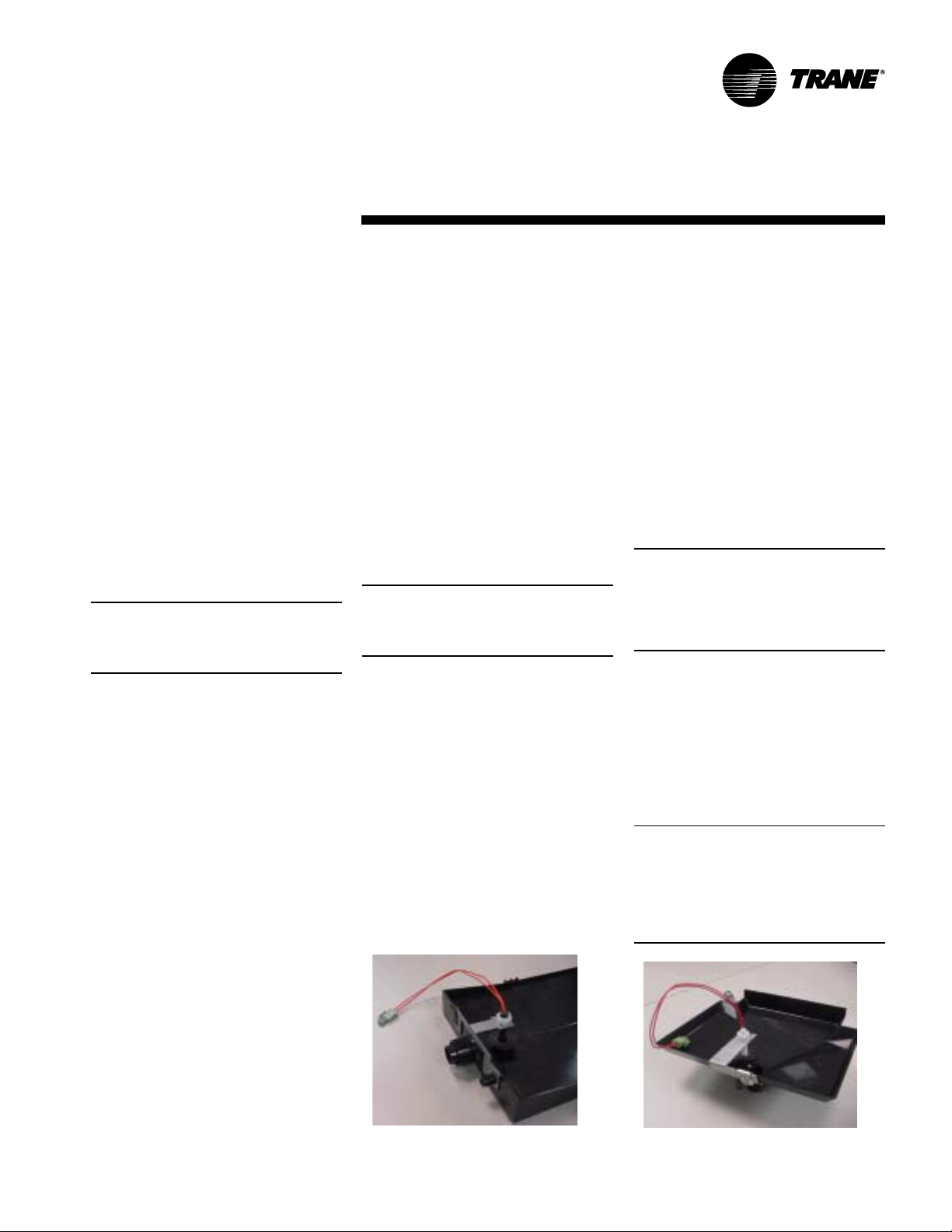
Condensate Overflow Detection Device
The condensate overflow detection
device is an option on fan-coil units with
either a T racer ZN010, ZN510, ZN520 or
the customer-supplied control interface.
The float switch, mounting bracket, and
coiled leads ship attached inside the
piping end pocket of the unit. Install the
switch by placing the hole or slot in the
bracket over the condensate overflow
drain (of the auxiliary drain pan) with the
switch float extending over the pan.
Secure the drain pan by attaching the
pan’ s bracket with the factory
provided clip. See Figures I-MR-1 and IMR-2.
Figure I-MR-1. Condensate float switch
installed in horizontal auxilliary drain pan.
3
/8-inch inside diameter
with a field supplied hose clamp.
Automatic Changeover Sensor
T wo-pipe changeover units with either
the T racer ZN010, ZN510, and ZN520
controls have an automatic changeover
sensor that determines heating or cooling
mode based on the supply water
temperature. On units with a factory
piping package, the factory straps the
changeover sensor to the piping supply
water pipe. See Figure I-MR-3 and I-MR-
4.
If the unit does not have a factory piping
package, the factory attaches the sensor
and coiled lead wires to the piping side
end panel. The installer should attach the
sensor parallel to and in direct contact
with the supply water pipe.
Note: The installer is responsible to
ensure the changeover sensor is installed
in a location that can sense active water
temperature. Otherwise, the unit may fail
to sense the correct operating mode and
disable temperature control.
When using field supplied three-way
valves, install the changeover sensor
upstream of the valve on the supply
water pipe. When using field supplied
two-way control valves, install the
changeover sensor in a location that will
detect active water temperature. The
unit must always be able to sense the
correct system water temperature,
regardless of the control valve position.
Note: The maximum length of the
automatic changeover wire cannot
exceed ten feet from the control panel. If
the sensor extends beyond the unit
chassis, use shielded conductors to
eliminate radio frequency interference
(RFI).
Figure I-MR-2. Condensate float switch
installed in vertical auxilliary drain pan.
UNT-SVX07A-EN 31
Page 32

Figure I-MR-3. Attach the changeover
sensor to the entering water pipe as shown
for changeover to work properly
Figure I-MR-4. Close-up view of the
changeover sensor
Figure I-MR-5. Manual coil air vent with set
screw
Automatic Electric Heat Lockout Switch
T wo-pipe fan-coil units with auxiliary
electric heat have an automatic electric
heat lockout switch that disengages the
electric heat when hydronic heat enables.
If the unit has a factory piping package
and electric heat, the factory attaches the
switch to the supply water pipe. When
the lockout switch detects the supply
water temperature above 95°F, it
disengages the electric heat. This
eliminates electric heat and hydronic heat
working simultaneously.
If the fan-coil unit does not have a factory
piping package, the switch and coiled lead
wires ship inside the piping side end
panel. The installer should position the
lockout switch on the supply water line of
the unit by sliding its spring connector
over the pipe. See I-MR-7.
V enting the Hydronic Coil
The hydronic coil contains a vent, either
manual or automatic, to release air from
the unit. This vent is not sufficient for
venting the water piping system in the
building.
The coil air vent is on the piping side,
above the coil connections on the unit.
See Figure I-MR-5 and I-MR-6. Perform
the following steps to vent the coil after
installing the unit.
1. Pressurize the building piping system
with water and vent any trapped air at
system vents.
2. For units with manual air vents, back
the set screw out to expel air from the
unit and then re-tighten the set screw.
The automatic air vent should require no
adjustment for the coil to vent. However ,
if the coil does not vent immediately,
unscrew the outer portion of the fitting to
expel air from the port.
If debris has become trapped in the vent,
completely remove the outer portion of
the fitting and clean.
mechanical
requirementsInstallation
Figure I-MR-7. Electric heat lock out switch
installed
External Insulating Requirements
Insulate and vapor seal surfaces colder
than surrounding air dew-point a to
prevent unplanned condensation. T rane
recommends field-insulation of the
following areas to prevent potential
condensate problems:
1. Supply and return water piping
connections
2. Condensate drain lines and
connections
3. Fresh air intake duct connections
4. Discharge duct connections
5. Wall boxes
Figure I-MR-6. Manual coil air vent with
Shrader fitting
32 UNT-SVX07A-EN
Page 33

mechanical
requirementsInstallation
Balancing The Manual Circuit Setter
Valve
The manual circuit setter valve is an
optional end valve supplied on the return
pipe of the factory piping package. The
valve allows the operator to regulate
water flow through the hydronic coil,
balance the water flow through the unit
with other units in the piping system, and
serves as a shutoff or end valve. See
Figure I-MR-8.
Follow the procedure below to set
maximum water flow through the coil.
1. Establish water flow through the coil.
Perform an open override of the valve if
the control valve is closed to the coil,
either manually or by T racer.
If the piping package has two-position,
normally closed valves: Drive open the
valve using a 24V signal.
If the piping package has two-position,
normally open valves: Manually drive
open the valve by removing power to
the valve.
If the piping package has modulating
valves: T o manually drive the valve
open, depress the button stem on top of
the valve and push the lever located on
the side of the valve to the full open
position.
2. For presetting, use the appropriate
valve curve shown in Chart I-MR-1 on
page 34 to determine which setting is
necessary to achieve the appropriate
pressure drop. The “M” line is the
appropriate line.
3. Carefully remove the Schrader
pressure port connection caps on the
manual circuit setter , since they will be
at the same temperature as the
pipeline.
4. Bleed all air from the hoses and meter
before reading the pressure drop. Refer
to the gauge operating instructions.
5. Adjust the circuit setter valve by
turning the valve stem until the
appropriate pressure drop is achieved.
6. After achieving the proper setting,
slightly loosen the two socket head cap
screws and rotate the memory stop
around until it touches the back side of
the indicator. Then tighten the screws to
securely set the open memory position.
The memory stop indicates the last set
open position.
7. If using a three-way valve: close the
control valve to the coil, with the
differential pressure meter still
connected. This will divert flow to the
bypass side of a three-way valve.
Adjust the balancing fitting to obtain the
same pressure drop across the circuit
setter valve as in step two when the
control valve was open to the coil.
Figure I-MR-8. Manual circuit setter valve
Figure I-MR-9. Automatic circuit setter valve
Figure I-MR-10. Automatic circuit setter
valve
UNT-SVX07A-EN 33
Page 34

mechanical
Installation
Note: Instructions for using this chart are on the previous page. For the manual
circuit setter provided with the fan-coil or Force Flo, use the 'M' line for reference.
requirements
Chart I-MR-1. Manual circuit setter valve, differential pressure vs. flow
34 UNT-SVX07A-EN
Page 35

Steam Piping
CAUTION
Coil Damage!
In all steam coil installations, the
condensate return connections must
be at the low point of the coil to
ensure condensate flows freely from
the coil at all times. Failure to do so
may cause physical coil damage from
water hammer, unequal thermal
stresses,freeze-up and/or corrosion.
1. Make piping connections to the steam
coil as shown in Figure I-MR-11. Cap the
unused connection.
2. The coil is already pitched within the
unit to provide proper pitch to drain
condensate out of the coil. Verify that
the unit has been properly leveled.
3. Install a
vacuum breaker in the unused
condensate return tapping as close as
possible to the coil.
4. V ent the vacuum breaker line to
atmosphere or connect it into the return
main at the discharge side of the steam
trap.
5. Pitch all steam supply and return mains
down a minimum of one inch per ten
feet in the direction of flow.
6. Do not drain the steam mains or takeoff through the coils. Drain the mains
ahead of the coils through a steam trap
to the return line.
7. Overhead returns require one psig of
pressure at the steam trap discharge
for each two-feet elevation to ensure
continuous condensate removal.
8. Proper steam trap selection and
installation is necessary for satisfactory
coil performance and service life. For
installation, use the following steps:
a. Position the steam trap discharge at
least 12 inches below the condensate
return connection. This provides
sufficient hydrostatic head pressure to
overcome trap losses and ensure
complete condensate removal.
1
/2-inch, 15-degree swing check
Figure I-MR-2. Typical Piping for Steam Coils
b. T rane recommends using flat and
thermostatic traps because of gravity
drain and continuous discharge
operation.
c. Use float and thermostatic traps with
atmospheric pressure gravity
condensate return, with automatic
controls or where the possibility of low
pressure supply steam exists.
d. Always install strainers as close as
possible to the trap inlet side. Reference
Figure I-MR-10 for an example of a
properly piped steam coil.
mechanical
requirementsInstallation
Code of System Components in Piping
Diagram
FT Float and thermostatic steam trap
BT Bucket steam trap
GV Gate valve
OV Automatic two-position (on-off) control valve
TV Automatic three-way control valve
VB Vacuum breaker
CV Check valve
ST Strainer
A V Automatic or manual air vent
vacuum breaker (if desired)
steam supply
plugged
condensate return
Figure I-MR-11. Main steam coil connection
diagram
UNT-SVX07A-EN 35
Page 36

electrical
requirementsInstallation
Unit Wiring Diagrams
Specific unit wiring diagrams are
provided inside each unit and can be
easily removed for reference.Use these
diagrams for connections or trouble
analysis. Wiring diagrams are attached
on the inside of the front panel of vertical
cabinet & recessed models and on the fan
and motor panel of vertical concealed &
all horizontal models.
Supply Power Wiring
WARNING
Hazardous V oltage w/Capacitors!
Disconnect all electric power , including
remote disconnects and discharge all
motor start/run capacitors before
servicing. Follow proper lockout/
tagout procedures to ensure the
power cannot be inadvertently
energized. For variable frequency
drives or other energy storing
components provided by T rane or
others, refer to the appropriate
manufacturer’ s literature for allowable
waiting periods for discharge of
capacitors. V erify with an appropriate
voltmeter that all capacitors have
discharged. Failure to disconnect
power and discharge capacitors
before servicing could result in death
or serious injury.
Refer to the unit nameplate to obtain the
minimum circuit ampacity (MCA) and
maximum fuse size (MFS) or maximum
circuit breaker (MCB) to properly size field
supply wiring and fuses or circuit
breakers.
Refer to the unit operating voltage listed
on the unit wiring schematic, submittal, or
nameplate. Reference the wiring schematic for specific wiring connections.
CAUTION
Use Copper Conductors Only!
Unit terminals are not designed to
accept other type conductors. Failure
to use copper conductors may result
in equipment damage.
Note: All field wiring should conform to
NEC and all applicable state and local
code requirements. The control panel box
is always on the end opposite the piping
connections. Access the control box by
removing the two screws that secure the
front cover . This will allow the panel to be
removed, to provide access to the
electrical components.
WARNING
Hazardous Electrical Shorts!
Insulate all power wire from sheet
metal ground. Failure to do so may
cause electrical shorts that could
result in death or serious injury.
If the unit does not have a disconnect
switch, the power leads and capped
ground wire are inside the control panel.
If the unit has a disconnect switch, the
power leads are wired to the junction box
switch on the control panel. Pull the
capped ground wire into the junction box.
Electrical Grounding
Restrictions
All sensor and input circuits are normally
at or near ground (common) potential.
When wiring sensors and other input
devices to the T racer controller, avoid
creating ground loops with grounded
conductors external to the unit control
circuit. Ground loops can affect the
measurement accuracy of the controller.
CAUTION
Equipment Damage!
Unit transformer IT1 provides power
to fan-coil unit only. Field connections
to the transformer IT1 may create
immediate or premature unit
component failure.
All input/output circuits (except isolated
relay contacts and optically isolated
inputs) assume a grounded source, either
a ground wire at the supply transformer
to control panel chassis, or an installer
supplied ground.
Wall Mounted Control
Interconnection Wiring
The installer must provide interconnection wiring to connect wall mounted
devices such as a fan mode switch or
zone sensor module.
Refer to the unit wiring schematic for
specific wiring details and point-to-point
wiring connections. Dashed lines indicate
field wiring on the unit wiring schematics.
All interconnection wiring must conform
to NEC Class 2 wiring requirements and
any state and local requirements.
Refer to T able I-ER-1 for the wire size
range and maximum wiring distance for
each device.
Recommendation: Do not bundle or run
interconnection wiring in parallel with or
in the same conduit with any high-voltage
wires (110V or greater). Exposure of
interconnection wiring to high voltage
wiring, inductive loads, or RF transmitters
may cause radio frequency interference
(RFI). In addition, improper separation
may cause electrical noise problems.
Therefore, use shielded wire (Beldon
83559/83562 or equivalent) in applications that require a high degree of noise
immunity. Connect the shield to the
chassis ground and tape at the other end.
Table I-ER-1. Maximum wiring distances for
low voltage controls, ft.
device wire size range
fan speed switch 14 - 22 AWG 500
zone sensor 16 - 22 AWG 200
Note: Do not connect any sensor or input
circuit to an external ground connection.
36 UNT-SVX07A-EN
Page 37

electrical
requirementsInstallation
Table I-ER-2. Low vertical free discharge
motors, 115 volt
size FLA HP (kW) R PM
03 0.7 .03 (0) H 1090
04 0.8 .03 (0) H 1090
06 1.1 .03 (0) H 1115
Note:
Actual rpm will vary with application and configuration.
M 770
L 560
M 750
L 560
M 760
L 560
Table I-ER-3. Decimal to fractional HP (kW)
conversion
FC Decimal Fraction
02 .03 1/30
03 .04 1/25
04 .05 1/20
06 .07 1/15
08 .12 1/8
10 .05 .07 1/20 1/15
12 .05 .12 1/20 1/8
low vertical .03 1/30
03, 04, 06
Note:
Values for fractional HP’ s (kW’s) are approximate values and
not necessarily the actual HP (kW).
.07 1/15
.05 1/20
.08 1/12
.06 1/16
.10 1/10
.13 1/8
.12 1/8
.16 1/6
.24 1/4
.13 1/8
.24 1/4
.06 .12 1/16 1/8
.10 .16 1/10 1/6
.13 .24 1/8 1/4
.06 .13 1/16 1/8
.10 .24 1/10 1/4
.13 .24 1/8 1/4
Table I-ER-4. Free discharge motors on units with two-row, electric, or steam coils
unit 115 volt 208-230 volt 277-480 volt rp m
size FLA hp (kW) FLA hp (kW) FL A hp (kW) H M L
02 0.6 .03 (.02) 0.3 .03 (.02) 0.2 .03 (.02) 980 840 655
03 0.7 .04 (.02) 0.4 .04 (.02) 0.3 .04 (.02) 980 780 580
04 0.9 .05 (.04) 0.5 .05 (.04) 0.4 .05 (.04) 1050 780 580
06 1.2 .07 (.05) 0.6 .07 (.05) 0.5 .07 (.05) 1030 780 580
08 1.4 .12 (.09) 0.9 .12 (.09) 0.6 .12 (.09) 1080 800 600
10 0.9 .05 (.04) 0.5 .05 (.04) 0.4 .05 (.04) 1050 780 580
1.2 .07 (.05) 0.6 .07 (.05) 0.5 .07 (.05) 1030 780 580
12 0.9 .05 (.04) 0.5 .05 (.04) 0.4 .05 (.04) 1050 780 580
1.4 .12 (.09) 0.9 .12 (.09) 0.6 .12 (.09) 108 800 600
Table I-ER-5. High static motors on units with two-row, electric, or steam coils
unit 115 volt 208-230 volt 277- 480 volt rpm
size FLA hp (kW) FL A hp (kW) FLA hp (kW) H M L
02 1.1 .07 (.05) 0.6 .07 (.05) 0.5 .07 (.05) 1480 1110 865
03 1.4 .08 (.06) 0.7 .08 (.06) 0.6 .08 (.06) 1400 1175 860
04 1.6 .10 (.07) 0.8 .10 (.07) 0.7 .10 (.07) 1475 1315 1070
06 2.6 .16 (.12) 1.2 .16 (.12) 1.0 .16 (.12) 1400 1070 855
08 3.4 .24 (.18) 1.4 .24 (.18) 1.1 .24 (.18) 1475 1285 975
10 1.6 .10 (.07) 0.8 .10 (.07) 0.7 .10 (.07) 1475 1315 1070
2.6 .16 (.12) 1.2 .16 (.12) 1.0 .16 (.12) 1400 1070 855
12 1.6 .10 (.07) 0.5 .10 (.07) 0.7 .10 (.12) 1475 1315 1240
3.4 .24 (.18) 0.9 .24 (.18) 1.1 .24 (.18) 1475 1285 975
Table I-ER-6. Free discharge motors on units with three and four-row coils
unit 115 volt 208-230 volt 277-480 volt rp m
size FLA hp(kW) FLA hpP (kW) FLA hp (kW) H M L
02 0.6 .03 (.02) 0.3 .03 (.02) 0.2 .03 (.02) 980 840 655
03 0.8 .05 (.04) 0.5 .05 (.04) 0.4 .05 (.04) 1080 800 600
04 1.0 .06 (.04) 0.6 .06 (.04) 0.5 .06 (.04) 1080 800 600
06 1.4 .12 (.09) 0.9 .12 (.09) 0.6 .12 (.09) 1080 800 600
08 1.7 .13 (.10) 1.0 .13 (.10) 0.8 .13 (.10) 1080 800 600
10 1.0 .06 (.04) 0.6 .06 (.04) 0.5 .06 (.04) 1080 800 600
12 1.0 .06 (.04) 0.6 .06 (.04) 0.5 .06 (.04) 1080 800 600
1.4 .12 (.09) 0.9 .12 (.09) 0.6 .12 (.09) 1080 800 600
1.7 .13 (.10) 1.0 .13 (.10) 0.8 .13 (.10) 1080 800 600
Table I-ER-7. High static motors on units with three and four-row coils
unit 115 volt 208-230 volt 277-480 volt rp m
size FLA hp (kW) FL A hp (kW) FLA hp (kW) H M L
02 1.1 .07 (.05) 0.6 .07 (.05) 0.5 .07 (.05) 1480 1110 865
03 1.3 .08 (.06) 0.7 .08 (.06) 0.5 .08 (.06) 1500 1355 1110
04 2.1 .13 (.10) 0.9 .13 (.10) 0.7 .13 (.10) 1580 1375 1240
06 3.4 .24 (.18) 1.4 .24 (.18) 1.1 .24 (.18) 1475 1285 975
08 3.4 .24 (.18) 1.4 .24 (.18) 1.1 .24 (.18) 1475 1285 975
10 2.1 .13 (.10) 0.9 .13 (.10) 0.7 .13 (.10) 1580 1375 1240
12 2.1 .13 (.10) 0.9 .13 (.10) 0.7 .13 (.10 ) 1580 1375 1240
Note: Actual rpm will vary with application and configuration. Size 10 & 12 units have two motors.
3.4 .24 (.18) 1.4 .24 (.18) 1.1 .24 (.18) 1475 1285 975
3.4 .24 (.18) 1.4 .24 (.18) 1.1 .24 (.18) 1475 1285 975
UNT-SVX07A-EN 37
Page 38

electrical
requirementsInstallation
Table I-ER-8. Fan-coil electric heat kW
Unit Size Unit Voltage kW kW kW kW kW kW kW kW kW kW kW
02 115 1.0 1.5 2.0
03 115 1.0 1.5 2.0 2.5
04 115 2.0 2.5 3.0
06 115 2.0 3.0
08 115 2.0 3.0
10 115 3.0
12 115 3.0
230 1.0 1.5 2.0
277 1.0 1.5 2.0
208 0.8 1.1 1.5 1.9
230 1.0 1.5 2.0 2.5
277 1.0 1.5 2.0 2.5
208 0.8 1.1 1.5 1.9 2.3
230 2.0 2.5 3.0
277 2.0 2.5 3.0
208 1.5 1.9 2.3 3.0
230 2.0 3.0 4.0 5.0 6.0
277 2.0 3.0 4.0 5.0 6.0
208 1.5 2.3 3.0 3.8 4.5 5.3
230 2.0 3.0 4.0 5.0 6.0 7.0
277 2.0 3.0 4.0 5.0 6.0 7.0
208 1.5 2.3 3.0 3.8 4.5 5.3 6.0
230 3.0 4.0 5.0 6.0 7.0 8.0
277 3.0 4.0 5.0 6.0 7.0 8.0
208 2.3 3.0 3.8 4.5 5.3 6.0
230 3.0 4.0 5.0 6.0 7.0 8.0 10.0
277 3.0 4.0 5.0 6.0 7.0 8.0 10.0
208 2.3 3.0 3.8 4.5 5.3 6.0
Table I-ER-9. Electric heat kW, low vertical fan-coils
unit size unit voltage kW kW kW kW
03 115 1.0 1.5 2.0
04 115 1.0 1.5 2.0 2.5
06 115 1.0 1.5 2.0 2.5
Low vertical units are only available with electric heat in combination with the two-row cooling coil.
Minimum Circuit Ampacity (MCA) and Maximum Fuse Size (MFS) Calculations for
Fan-Coils with Single Phase Electric Heat
Heater amps = (heater kW x 1000)/heater voltage
Note: Use 120V heater voltage for 115V units. Use 240V heater voltage for 230V units.
MCA = 1.25 x (heater amps + all motor FLAs)
MFS or HACR type circuit breaker = (2.25 x largest motor FLA) + second motor FLA
+ heater amps (if applicable)
HACR (heating, air-conditioning and refrigeration) type circuit breakers are required in
the branch circuit wiring for all fan-coils with electric heat.
Select a standard fuse size or HACR type circuit breaker equal to the MCA.
Use the next larger standard size if the MCA does not equal a standard size.
Standard fuse sizes are: 15, 20, 25, 30, 35, 40, 45, 50, 60 amps
Fan-coil electric heat MBh = (heater kW) (3.413)
38 UNT-SVX07A-EN
Page 39

electrical
Installation
requirements
Table I-ER-10. Force Flo single-stage, max kW electric heat
unit heater heater
size volts hz phase wires kW amps/ph
208 1 2 2.25 10.9
240 1 2 3.0 12.5
02 277 60 1 2 3.0 10.9
208 3 3 2.25 6.3
240 3 3 3.0 7.3
480 3 4 3.0 3.7
208 1 2 4.5 21.7
240 1 2 6.0 25.0
03 277 60 1 2 6.0 21.7
208 3 3 4.5 12.6
240 3 3 6.0 14.5
480 3 4 6.0 7.3
208 1 2 5.7 27.5
240 1 2 7.5 31.3
04 277 60 1 2 7.5 27.1
208 3 3 5.7 15.9
240 3 3 7.5 18.1
480 3 4 7.5 9.1
208 1 2 7.9 38.0
240 1 2 10.5 43.8
06 277 60 1 2 10.5 38.0
208 3 3 7.9 21.9
240 3 3 10.5 25.3
Note: All data based on individual units. Electric heat will operate only with fan at high speed.
480 3 4 10.5 12.7
Table I-ER-11. Force Flo single stage, low kW electric heat
unit size voltage # wires kW amps/ph kW amps/ph kW amps/ph
02 208/60/1 2 0.75 3.7 1.5 7.3
03 208/60/1 2 2.25 10.9
04 208/60/1 2 2.25 10.9
06 208/60/1 2 2.25 10.9 3.3 15.9
08 208/60/1 2 2.25 10.9 3.3 15.9 4.5 21.7
10 208/60/1 2 2.25 10.9 3.3 15.9 5.7 27.5
12 208/60/1 2 2.25 10.9 3.3 15.9 6.6 31.8
Note: All data based on individual units. Electric heat will operate only with fan at high speed.
240/60/1 2 1.0 4.2 2.0 8.4
277/60/1 2 1.0 3.7 2.0 7.3
240/60/1 2 3.0 12.5
277/60/1 2 3.0 10.9
208/60/3 3 2.25 6.3
240/60/3 3 3.0 7.3
480/60/3 4 3.0 3.7
240/60/1 2 3.0 12.5
277/60/1 2 3.0 10.9
208/60/3 3 2.25 6.3
240/60/3 3 3.0 7.3
480/60/3 4 3.0 3.7
240/60/1 2 3.0 12.5 4.5 18.8
277/60/1 2 3.0 10.9 4.5 16.3
208/60/3 3 2.25 6.3 3.3 9.2
240/60/3 3 3.0 7.3 4.5 10.9
480/60/3 4 3.0 3.7 4.5 5.5
240/60/1 2 3.0 12.5 4.5 18.8 6.0 25.0
277/60/1 2 3.0 10.9 4.5 16.3 6.0 21.7
208/60/3 3 2.25 6.3 3.3 9.2 4.5 12.5
240/60/3 3 3.0 7.3 4.5 10.9 6. 0 14.5
480/60/3 4 3.0 3.7 4.5 5.5 6.0 7.3
240/60/1 2 3.0 12.5 4.5 18.8 7.5 31.3
277/60/1 2 3.0 10.9 4.5 16.3 7.5 27.1
208/60/3 3 2.25 6.3 3.3 9.2 5.7 15.9
240/60/3 3 3.0 7.3 4.5 10.9 7. 5 18.1
480/60/3 4 3.0 3.7 4.5 5.5 7.5 9.1
240/60/1 2 3.0 12.5 4.5 18.8 9.0 37.5
277/60/1 2 3.0 10.9 4.5 16.3 9.0 32.5
208/60/3 3 2.25 6.3 3.3 9. 2 6.6 18.4
240/60/3 3 3.0 7.3 4.5 10.9 9. 0 21.7
480/60/3 4 3.0 3.7 4.5 5.5 9.0 10.9
UNT-SVX07A-EN 39
Page 40

electrical
Installation
requirements
Table I-ER-12. Force Flo 2-stage electric heat
unit 1st stage total total
size volts hz phase wires kW kW amps/ph
02 2 7 7 60 1 2 1.0 3.0 10.9
03 2 7 7 60 1 2 2.0 6.0 21.7
04 2 7 7 60 1 2 2.5 7.5 27.1
06 2 7 7 60 1 2 4.5 10.5 38.0
08 2 7 7 60 1 2 6.0 13.5 48.8
10 2 7 7 60 1 2 8.0 18.0 65.0
12 2 7 7 60 1 2 9.0 20.0 72.3
Note: When both stages are on, the electric heat will operate only when fan is in high speed. All data based on
individual units.
208 1 2 0.75 2.25 10.9
240 1 2 1.0 3.0 12.5
208 3 3 0.75 2.25 6.3
240 3 3 1.0 3.0 7.3
480 3 4 1.0 3.0 3.7
208 1 2 1.5 4.5 21.7
240 1 2 2.0 6.0 25.0
208 3 3 1.5 4.5 12.6
240 3 3 2.0 6.0 14.5
480 3 4 2.0 6.0 7.3
208 1 2 1.9 5.7 27.5
240 1 2 2.5 7.5 31.3
208 3 3 1.9 5.7 15.9
240 3 3 2.5 7.5 18.1
480 3 4 2.5 7.5 9.1
208 1 2 3.4 7.9 38.0
240 1 2 4.5 10.5 43.8
208 3 3 3.4 7.9 21.9
240 3 3 4.5 10.5 25.3
480 3 4 4.5 10.5 12.7
208 1 2 4.5 10.1 48.8
240 1 2 6.0 13.5 56.3
208 3 3 4.5 10.1 28.2
240 3 3 6.0 13.5 32.5
480 3 4 6.0 13.5 16.3
208 1 2 6.0 13.5 65.0
240 1 2 8.0 18.0 75.0
208 3 3 6.0 13.5 37.6
240 3 3 8.0 18.0 43.3
480 3 4 8.0 18.0 21.7
208 1 2 6.8 15.0 72.3
240 1 2 9.0 20.0 83.4
208 3 3 6.8 15.0 41.7
240 3 3 9.0 20.0 48.2
480 3 4 9.0 20.0 24.1
40 UNT-SVX07A-EN
Page 41
installation
procedureInstallation
Installing the Unit
Follow the procedures below to install the
unit properly. Reference the “Dimensions
and Weights” section for specific unit
dimensions and mounting hole locations.
V ertical Units
CAUTION
Electrical Wiring!
Do not allow electrical wire to fall
between the unit and installation
surface. Failure to comply may result
in electrical shorts or difficulty
accessing wires.
Install vertical units in an upright position
using the
hanger holes, located on the back of unit.
The hanger holes allow a maximum
shank size of
rods or lag screws (installer provides).
1. Prepare wall openings for recessed
2. If the unit has leveling legs, adjust them
3. Mark the position of the keyslot hanger
4. Insert the threaded rods or lag screws
5. Remove the front panel (cabinet unit
6. Position the hanger holes, located on
7. Complete piping and wiring
8. Install the front panel before starting
On cabinet units, replace the front panel
by aligning the bottom tabs on the unit
with the respective slots on the panel
5
/8-inch diameter double key slot
5
/16-inch diameter threaded
units. Reference unit submittal for each
unit size dimensions. When installing
vertical units, consideration should be
given for units with an outside air
intake.
correctly to level unit.
holes on the wall according to the
dimensions given in the
Weights
and size. Align the hole locations evenly.
in the wall before setting the unit in
place.
only) by lifting it upward.
the back of the unit, over the rod or lag
screw heads, pushing the unit
downward to properly position.
connections, in addition to any
necessary ductwork to the unit as
instructed in the following sections.
Ensure that the auxiliary drain pan is in
position on fan-coil units.
the unit.
section for each unit model
Dimensions &
bottom. Slide the front panel down onto
the tabs while holding the panel close as
possible to the cabinet. While the bottom
tabs are engaged, slide the front panel
upward enough to allow the top engaging
edge of the front panel to lap over the
engaging edge of the unit. This should
allow the panel to drop down and lock
into position.
On recessed units, install the front panel
by aligning and locking together the
interlocking support channel of the panel
and unit. While holding the panel against
the unit, tighten the screws at the top of
the panel until it fits tight against the unit’s
front. Do not over tighten the screws.
CAUTION
Motor Overload!
All unit panels and filters must be in
place prior to unit startup. Failure to
have panels and filters in place may
cause motor overload.
Horizontal Units
Install horizontal units suspended from
the ceiling using the four
double key slot hanger holes, located on
the top of the unit. The hanger holes allow
a maximum shank size of
diameter threaded rods or lag screws
(installer provided). Follow the installation
procedure below.
Note: Follow the requirements of
National Fire Protection Association
(NFPA) Standard 90A or 90B, concerning
the use of concealed ceiling spaces as
return air plenums.
1. Prepare the ceiling opening for
recessed units. Reference the unit
submittals for dimensions.
2. Position and install the suspension rods
or a suspension device (supplied by
installer) according to the unit model
and size in the
section.
3. On cabinet units, remove the bottom
panel by using a
to unscrew fasteners. Swing the panel
down and lift outward.
4. Level the unit by referencing the
chassis end panels. Adjust the
suspension device.
Dimensions & Weights
5
/8-inch diameter
5
/16-inch
5
/32-inch Allen wrench
5. Complete piping and wiring
connections.
necessary ductwork as instructed in the
following sections. Ensure that the
auxiliary drain pan is in position on fancoil units.
6. Install the bottom panel before starting
the unit.
7. Ensure condensate drain line is pitched
one inch per ten feet of pipe away from
the fan-coil unit.
Cabinet units
Install the bottom panel by placing the
hinged end on the unit’ s hinged end
(always at the return end of the unit).
Reference the
section for keyslot hanger hole locations.
Swing the panel upward into position.
Secure the panel with the fasteners
provided. Do not overtighten the
fasteners.
Recessed units
Reference the
section for mounting locations and unit
weights. Follow the procedure below and
reference Figure I-IP-1.
1. Insert the mounting bolts through the
panel brackets of the trim ring and
secure to the hanger holes on the unit.
Tighten the mounting bolts to pull the
trim ring snug against the finished
ceiling.
2. Install the bottom panel by placing the
hinged end on the trim ring hinged end
(always at the unit’ s return end).
3. Adjust the expansion collar’s inner duct
(only on fan-coil units with a bottom
return) to ensure a tight fit against the
insulation located on the perimeter of
the bottom panel’s return louver.
4. Close the s-hook on each end of safety
chain assembly. Insert s-hooks through
holes in unit and door. Close s-hook on
door.
5. Insert retaining screws through bottom
panel door and place retaining rings on
screws.
6. Swing the bottom panel upward into
position. Hook the safety chain to the
bottom panel and the unit. Tighten the
panel to the unit with the fasteners
provided.
Dimensions & Weights
Dimensions & Weights
UNT-SVX07A-EN 41
Page 42

CAUTION
Unit Leveling!
All unit panels and filters must be in
place prior to unit start-up. Failure to
have panels and filters in place may
cause motor overload.
installation
procedureInstallation
Note: The trim ring assembly cannot
accomodate unlevel ceilings.
Note: On sizes 8, 10, & 12 center installation position and use 2 or 3.5-inch bolts,
whichever is best suited for installation.
Also, install two safety chains assemblies
on these sizes.
Note: Expansion collar is furnished with
fan-coil with bottom return only. The
collar is not necessary for Force Flo units.
Figure I-IP-1. Installing the trim ring assembly on horizontal recessed units.
42 UNT-SVX07A-EN
Page 43

installation
Wall-Mounted Control Options
Installation
Figure I-IP-2. Zone sensor with off/
auto/high/low fan speeds, setpoint
knob, on/cancel, and comm jack.
procedure
Figure I-IP-4. Zone sensor with
setpoint knob, on/cancel, & comm
jack.
Figure I-IP-3. Zone sensor with on/cancel
and comm jack.
UNT-SVX07A-EN 43
Figure I-IP-5. Zone sensor only,
Figure I-IP-6. Digital zone sensor option
Page 44
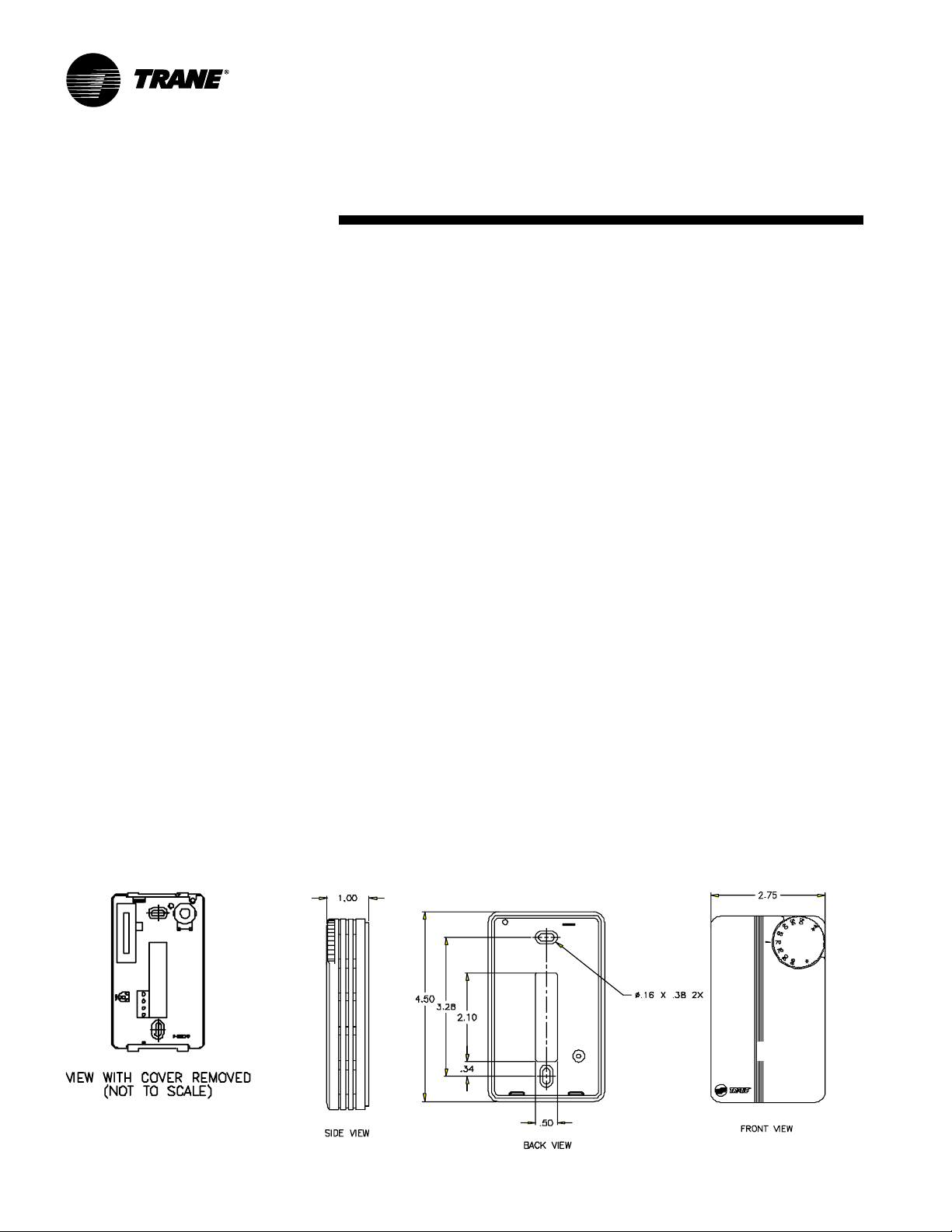
installation
procedureInstallation
Installing Wall Mounted
Controls
Reference the wall-mounted zone sensor
dimensions in Figure I-IP-6. Position the
controller on an inside wall three to five
feet above the floor and at least 18
inches from the nearest outside wall.
Installing the controller at a lower height
may give the advantage of monitoring
the temperature closer to the zone, but it
also exposes the controller to airflow
obstructions. Ensure that air flows freely
over the controller.
Before beginning installation, follow the
wiring instructions below. Also, refer to
the unit wiring schematic for specific
wiring details and point connections.
Wiring Instructions
Avoid mounting the controller in an area
subject to the following conditions:
• Dead spots, such as behind doors or in
corners that do not allow free air
circulation.
• Air drafts from stairwells, outside doors,
or unsectioned hollow walls.
• Radiant heat from the sun, fireplaces,
appliances, etc.
• Airflow from adjacent zones or other
units.
• Unheated or uncooled spaces behind
the controller, such as outside walls or
unoccupied spaces.
• Concealed pipes, air ducts, or chimneys
in partition spaces behind the controller.
Fan Mode Switch Installation
The fan mode switch ships loose inside
the unit accessory bag. Follow the steps
below to install the fan mode switch.
Items needed:
2 x 4 electrical junction box
1. Remove the brown wire if not using a
field-supplied damper. Remove the
terminals, cut and strip wires as
required for installation.
2. Level and position a 2 x 4 electrical
junction box. Follow the instructions
given in the “Interconnection Wiring”
section and route the wires as shown in
the wiring diagram. Refer to the typical
wiring diagram or to the unit specific
diagram on the unit.
3. Position the fan mode switch over the
junction box with the two screws
supplied.
Zone Sensor Installation
Follow the procedure below to install the
zone sensor module.
1. Note the position of the setpoint
adjustment knob and gently pry the
adjustment knob from the cover using
the blade of a small screwdriver .
2. Insert the screwdriver blade behind the
cover at the top of the module and
carefully pry the cover away from the
base.
3. To install the zone sensor module
without a junction box (directly to the
wall):
a. Using the module base as a
template, mark the the rectangular
cutout for the control wiring and module
installation holes. Ensure the base is
level.
b. Set the base aside and make the
cutout. Then, drill two
holes approximately one-inch deep.
Insert and fully seat the plastic anchors.
c. Pull the control wires through the
cutout and attach the module to the wall
using the screws provided.
4. T o install the zone sensor module to a
standard junction box:
a. Level and install a 2“ x 4” junction
box (installer supplied) vertically on the
wall.
b. Pull the control wires through the
cutout. Attach the module to the wall
using the screws provided.
5. Strip the insulation on the
interconnection wires back 0.25 inch
and connect to TB1. Screw down the
terminal blocks.
6. Replace the zone sensor cover and
adjustment knob.
If installing a T racer
ZN520 zone sensor , see the Tracer
Summit Communication section for more
information.
3
/16” diameter
ZN510 or T racer
Figure I-IP-6. Wall mounted zone sensor dimensions.
44 UNT-SVX07A-EN
Page 45

installation
Installation
Installation Checklist
The following checklist is only an
abbreviated guide to the detailed
installation procedures given in this
manual. Use this list to ensure all
necessary procedures are complete. For
more detailed information, refer to the
appropriate sections in this manual.
WARNING
Hazardous Voltage w/Capacitors!
Disconnect all electric power,
including remote disconnects and
discharge all motor start/run
capacitors before servicing. Follow
proper lockout/tagout procedures to
ensure the power cannot be
inadvertently energized. V erify with
an appropriate voltmeter that all
capacitors have discharged. Failure to
disconnect power and discharge
capacitors before servicing could
result in death or serious injury.
! 1. Inspect the unit for shipping damage.
! 2. Level installation location to support
the unit weight adequately. Make all
necessary wall or ceiling openings to
allow adequate air flow and service
clearances.
! 3. Ensure the unit chassis is installed
level.
CAUTION
Unit Leveling!
The unit must be installed level (zero
tolerance) in both horizontal axis for
proper operation. Do not use the coil
or drain pan as the reference point
because the coil may be pitched and
the drain pan has an inherent positive
slope to provide proper drainage.
! 4. Verify that wall and ceiling openins
are properly cut per the unit submittals.
! 5. Verify that installation of horizontal
concealed units meets the national Fire
procedure
Protection Association (N.F.P.A.)
Standard 90A or 90B concerning the
use of concealed ceiling spaces as
return air plenums. Verify correct ceiling
opening dimensions on unit submittals.
Secure the unit and any accessory items
properly to the wall or ceiling support
rods.
! 6. Complete all piping connections
correctly.
! 7. Check field sweat connections for
leaks and tighten the valve stem
packing, and piping pkg unions if
necessary.
! 8. Install the auxiliary drain pan
properly under piping package on fancoil units.
! 9. Complete condensate drain line
connections on fan-coil units.
! 10. Pitch condensate drain line away
from fan-coil one-inch drop per ten feet
of pipe.
! 11. Install automatic changeover
sensor option on the supply water line, if
applicable.
! 12. Install automatic electric heat
lockout switch option on the supply
water line, if applicable.
!13. Install condensate overflow switch
option correctly on the auxiliary drain
pan, if applicable.
! 14. Ensure the low temperature
detection device option is correctly
installed.
!15. Complete all necessary duct
connections.
!16. Complete all interconnection wiring
for the wall mounted fan mode switch
or zone sensor per the wiring schematic
and guidelines established in the “Wall
Mounted Control Interconnection
Wiring” section.
! 17. Install the wall mounted fan mode
switch, or zone sensor module options
properly.
!18. Connect electrical supply power
according to the NEC and unit wiring
diagrams.
! 19. Remove any miscellaneous debris,
such as sheetrock dust, that may have
infiltrated the unit during construction.
! 20. Replace the air filter as required.
UNT-SVX07A-EN 45
Page 46

pre-startup
requirementsInstallation
Communication Wiring
Units with T racer ZN510 and ZN520 Only
Communications
T racer ZN510 and ZN520 controllers are
LonT alk
T rane Tracer Summit building
management system. Reference the unit
wiring diagram or submittals.
Ground shields at each T racer ZN510 and
ZN520, taping the opposite end of each
shield to prevent any connection between the shield and anther ground.
Refer to T rane publication,
EN Installation, Operation and Programming Guide
wiring diagram.
Communication wire must conform to
the following specification:
1. Shielded twisted pair 18 AWG
2. Capacitance 23 (21-25) picofarads (pF)
3. Listing/Rating – 300V 150C NEC 725-2
4. T rane Part No. 400-20-28 or equivalent,
Note: Communication link wiring is a
shielded, twisted pair of wire and must
comply with applicable electrical codes.
Follow these general guidelines when
installing communication wiring on units
with a T racer ZN510 or ZN520 controller:
• Maintain a maximum 5000 ft.
• Install all communication wiring in
• Solder the conductors and insulate
• Do not pass communication wiring
• Do not run power in the same conduit or
Note: Y ou do not need to observe polarity
for LonT alk communication links.
®
devices that interface with the
CNT -SVX04A-
, for the communication
per foot
(b) Class 2 Type CL2P
available through T rane BAS Buying
Group Accessories catalog.
aggregate run.
accordance with the NEC and all local
codes.
(tape) the joint sufficiently when splicing
communication wire. Do not use wire
nuts to make the splice.
between buildings because the unit will
assume different ground potentials.
wire bundle with communication link
wiring.
Device Addressing
LonT alk devices are given a unique
address by the manufacturer . This
address is called a Neuron ID. Each T racer
ZN510 and ZN520 controller can be
identified by its unique Neuron ID, which
is printed on a label on the controller’s
logic board. The Neuron ID is also
displayed when communication is
established using T racer Summit or
Rover service tool. The Neuron ID format
is 00-01-64-1C-2B-00.
Wire Characteristics
Controller communication-link wiring
must be low capacitance, 18-gage,
shielded, twisted pair with stranded,
tinned-copper conductors. For daisy chain
configurations, limit the wire run length to
5,000 ft. T ruck and branch configurations
are significantly shorter . LonTalk wire
length limitations can be extended
through the use of a link repeater.
Recommended
Communication Wiring
Practices
The following guidelines should be
followed while installing communication
wire.
• LonT alk is not polarity sensitive. Trane
recommends that the installer keep
polarity consistent throughout the site.
• Only strip away two-inches maximum of
the outer conductor of shielded cable.
• Make sure that the 24V AC power
supplies are consistent in how they are
grounded. Avoid sharing 24VAC
between LonT alk UCMs.
• Avoid over-tightening cable ties and
other forms of cable wraps. A tight tie
or wrap could damage the wires inside
the cable.
• Do not run LonT alk cable alongside or in
the same conduit as 24V AC power.
• In an open plenum, avoid lighting
ballasts, especially those using 277V AC.
• Do not use a trunk and branch
configuration, if possible. T runk and
branch configurations shorten the
distance cable can be run.
46 UNT-SVX07A-EN
Page 47

pre-startup
Installation
Pre-Startup Checklist
Complete this checklist after installing
the unit to verify all recommended
installation procedures are complete
before unit startup. This does not replace
the detailed instructions in the
appropriate sections of this manual.
Disconnect electrical power before
performing this checklist. Always read
the entire section carefully to become
familiar with the procedures.
WARNING
Voltage w/Capacitors!
Disconnect all electric power,
including remote disconnects and
discharge all motor start/run
capacitors before servicing. Follow
proper lockout/tagout procedures to
ensure the power cannot be
inadvertently energized. For variable
frequency drives or other energy
storing components provided by
Trane or others, refer to the
appropriate manufacturer’s literature
for allowable waiting periods for
discharge of capacitors. V erify with
an appropriate voltmeter that all
capacitors have discharged. Failure
to disconnect power and discharge
capacitors before servicing could
result in death or serious injury.
Receiving
! Inspect unit and components for
shipping damage. File damage claims
immediately with the delivering
carrier.
! Check unit for missing material. Look
for ship-with options and sensors that
may be packaged separately from the
main unit. See the “Receiving and
Handling” section.
! Check nameplate unit data so that it
matches the sales order requirements.
Hazardous
requirements
Unit Location
1. Ensure the unit location is adequate for
unit dimensions, ductwork, piping, and
electrical connections.
2. Ensure access and maintenance
clearances around the unit are
adequate.
Unit Mounting
1. Ensure unit is installed level.
Component Overview
1. Ensure the fan rotates freely in the
correct direction.
2. Ensure all unit access panels and air
grilles are in place.
3. V erify that a clean air filter is in place.
4. Properly set the damper position to
meet the fresh air requirement.
Unit Piping
1. Properly vent the hydronic coil to allow
water flow through the unit.
2. Units with deluxe piping package:
Tighten unions adequately .
3. Set water flow to the unit properly if
unit piping has the circuit setter valve.
4. Check strainers (if supplied) for debris
after apply system water.
5. Install the auxiliary drain pan and route
the main drain pan hoses to the
auxiliary drain pan on vertical fan-coil
units.
6. Verify the condensate drain piping is
complete for the unit drain pan.
7. Ensure the drain pan and condensate
line are not obstructed. Remove any
foreign matter that may have fallen into
the drain pan during installation.
Electrical
# Check all electrical connections for
tightness.
Note: Some circumstances may require
the unit to run before building construction is complete. These operating
conditions may be beyond the design
parameters of the unit and may adversely affect the unit.
UNT-SVX07A-EN 47
Page 48

startupInstallation
T racer™ ZN510 & ZN520 Unit
Startup
Refer to the T rane publication,
Installation, Operation and Programming
for T racer ZN510 and CNT-
Guide
SVX04A-EN for T racer ZN520. The
factory pre-programs the Tracer ZN510
and ZN520 with default values to control
the temperature and unit airflow. Use
T racer Summit building automation
system or Rover™ software to change
the default values.
Follow the procedure below to operate
the T racer ZN510 or ZN520 in a standalone operation:
1. T urn power on at the disconnect switch
option.
2. Position the fan mode switch to either
high, medium, low, or the auto position.
3. Rotate the setpoint dial on the zone
CNT -IOP-1
sensor module to 55°F for cooling or
85°F for heating.
The appropriate control valve will actuate
assuming the following conditions:
1. Room temperature should be greater
than 55°F and less than 85°F.
2. For a 2-pipe fan-coil unit with an
automatic changeover sensor, the
water temperature input is appropriate
for the demand placed on the unit. For
example, cooling operation is
requested and cold water (5° lower
than room temperature) flows into the
unit.
3. Select the correct temperature
setpoint.
Note: Select and enable zone sensor
temperature settings to prevent freeze
damage to unit.
48 UNT-SVX07A-EN
Page 49

general
General Information
Relay Board
The relay board is a new component on
all models (except those with a unitmounted, line-voltage fan speed switch)
that replaces all the loose wires in the
control box. It consolidates many control
components onto one board, therefore
making it easy to troubleshoot in the field.
There is an LED on the board that
indicates when power is supplied to the
board. All connections are made to match
up only with the applicable component to,
thus prevent miswiring. Factory switches
are pre-set and locked in place with locktight. The switch settings can be broken if
field-modifications are needed. However,
switches must be properly set for the unit
to operate safely and properly. See
Figure O-GI-1.
Manual Fan Mode Switch
The manual fan mode switch is available
with a four-position switch (off-hi-med-lo)
allows manual fan mode selection and is
available unit or wall mounted. See
Figure O-GI-2.
Operation
The unit-mounted option operates on line
voltage. The wall mounted option is lowvoltage and has three 24-volt relays using
a factory-wired transformer and relays to
control the fan motor.
T racer ZN010 & ZN510
T racer ZN010 is a stand-alone device that
controls fan-coils and cabinet heaters.
T racer ZN510 can be stand-alone or use
peer-to-peer communications.
The controller is easily accessible in the
control end panel for service. The control
end panel is on the end of the unit
opposite the piping. Reference Figure OGI-3.
information
Figure O-GI-2. Fan speed switch
Figure O-GI-1. Relay board
Figure O-GI-3. Tracer ZN010 board
UNT-SVX07A-EN 49
Page 50

sequence of
Operation
Fan Mode Switch Operation
Off
Fan is turned off, two-position damper
option spring-returns closed.
Hi, Med, Lo
Fan runs continuously at the selected
speed. The two-position damper option
opens to an adjustable mechanical stop
position.
T racer ZN010 & ZN510
Operation
Off
Fan is off; control valves and fresh air
damper option close. Low air
temperature detection option is still
active.
Auto (Fan Cycling)
Fan and fresh air damper cycle with
control valve option to maintain setpoint
temperature. In cooling mode, the fan
cycles from off to medium and in heating
mode it cycles from off to low. When no
heating or cooling is required, the fan is
off and the fresh air damper option
closes.
Low/Med/High (Continuous Fan)
Fan operates continuously while control
valve option cycles to maintain setpoint
temperature. Fresh air damper option is
open.
operation
T racer ZN520 Operation
Off
Fan is off; control valve options and fresh
air damper options close. The low air
temperature detection option is still
active.
Auto
Fan speed control in the auto setting
allows the modulating (3-wire floating
point) or 2–position control valve option
and three-speed fan to work
cooperatively to meet precise capacity
requirement, while minimizing fan speed
(motor/energy/acoustics ) and valve
position (pump energy, chilled water
reset ). As the capacity requirement
increases at low fan speed, the water
valve opens. When the low fan speed
capacity switch point is reached, the fan
switches to medium speed and the water
valve repositions to maintain an
equivalent capacity. The reverse
sequence takes place with a decrease in
required capacity.
Low/Med/High
The fan runs continuously at the selected
speed and the valve option will cycle to
meet setpoint.
50 UNT-SVX07A-EN
Page 51

sequence of
Sequence of Operation
T racer ZN010 and ZN510
Note: this section applies only to units
with a T racer ZN010 or ZN510 controller.
Power-Up Sequence
When 24 V AC power is initially applied to
the T racer ZN010 or ZN510, the following
sequence occurs:
1. All outputs are controlled off.
2. T racer ZN010 and ZN510 reads all
input values to detemine initial values.
3. The random start time (0-25 seconds)
expires.
4. Normal operation begins.
Entering Water T emperature Sampling
Function
Both T racer ZN010 and ZN510 use an
entering water temperature sampling
function to test for the correct water
temperature for the unit operating mode.
For all applications not involving
changeover, the water temperature does
not affect unit operation.
The entering water temperature sampling function opens the main hydronic
valve, waits no more than three minutes
to allow the water temperature to
stabilize, then measures the entering
water temperature to see if the correct
water temperature is available.
The entering water must be five degrees
or more above the space temperature to
allow hydronic heating and five degrees
or more below the space temperature to
allow hydronic cooling.
If the correct water temperature is
available, the unit begins normal heating
or cooling operation. If the measured
entering water temperature is too low or
high, the controller closes the valve and
waits 60 minutes before attempting to
sample the entering water . Reference
T able O-SO-1.
Operation
Table O-SO-1. Unit mode as related to water temperature
unit type EWT sensor required? coil water temperature
2-pipe changeover yes COOLS if: space temp - EWT ≥ 5°F
4-pipe changeover yes COOLS if: space temp - EWT ≥ 5°F
2-pipe heating only no hot water assumed
2-pipe cooling only no cold water assumed
4-pipe heat/cool no cold water assumed in main coil
Binary Inputs
BIP1: Low T emperature Detection
Option
The factory hard wires the low
temperature detection sensor to binary
input #1 (BIP1) on the T racer ZN010 and
ZN510. The sensor defaults normally
closed (N.C.), and will trip off the unit on a
low temperature diagnostic when
detecting low temperature. In addition,
the T racer ZN010 and ZN510 control unit
devices as listed below:
operation
HEATS if: EWT - space temp ≥ 5°F
HEATS if: EWT - space temp≥ 5°F
hot water assumed in aux. coil
BIP3: Occupancy Sensor
Binary input #3 (BIP3) on T racer ZN010
and ZN510 is available for field- wiring an
occupancy sensor , such as a binary
switch or a timeclock, to detect
occupancy. The sensor can be either
normally open or normally closed.
Reference T able O-SO-2.
Binary Outputs
Reference Table O-SO-3 for the Tracer
ZN010 and ZN510’ s six binary outputs.
fan: off
valves: open
electric heat: off
damper: closed
Note: See the “Diagnostics” section for
more information.
BIP2: Condensate Overflow Detection
Option
The factory hard wires the condensate
overflow sensor to binary input #2 (BIP2)
on the T racer ZN010 and ZN510. The
sensor defaults normally closed (N.C.),
and will trip off the unit on a condensate
overflow diagnostic if condensate
reaches the trip point. In addition, the
T racer ZN010 and ZN510 control unit
Table O-SO-3. Binary outputs
binary output description pi n
BOP1 fan high speed J1-1
BOP2 fan medium speed J1-2
BOP3 fan low speed J1-4
BOP4 main valve J1-5
BOP5 auxiliary valve/electric heat J1-6
BOP6 2-position fresh air damper J1-7
Notes:
1. In a four-pipe application, BOP4 is used for cooling and
BOP5 is used for heating.
2. If no valves are ordered with the unit, the factory default
for the Tracer ZN010 and ZN510 controller are:
BOP4 configured as normally closed
BOP5 configured as normally open
3. If the fresh air damper option is not ordered on the unit,
BOP6 will be configured as none.
devices as listed below:
fan: off
valves: closed
electric heat: off
Table O-SO-2. Occupancy sensor state table
sensor type sensor position unit occupancy mode
normally open open occupied
normally open closed unoccupied
normally closed open unoccupied
normally closed closed occupied
UNT-SVX07A-EN 51
Page 52

sequence of
Analog Inputs
Both T racer ZN010 and ZN510 accept a
maximum of five analog inputs.
Reference T able O-SO-4.
Zone Sensors
The zone sensors available with the
T racer ZN010 and ZN510 provide up to
three different inputs
1. Space temperature measurement
(10KΩ thermistor)
2. Local setpoint
3. Fan mode switch
Wall mounted zone sensors include a
thermistor as a component of the
internal printed circuit board. Unit
mounted zone sensors use a sensor
placed in the unit’ s return air stream.
Each zone sensor is equipped with a
thumbwheel for setpoint adjustment.
Fan Mode Switch
The zone sensor may be equipped with a
fan mode switch. The fan mode switch
offers selections of off, low, medium,
high, or auto.
Supply Fan Operation
Reference T able O-SO-5 for fan mode
operation. Reference T able O-SO-5 for
fan mode operation. T racer ZN010 and
ZN510 will operate in either continuous
fan or fan cycling mode. The fan cycles
when the fan mode switch is placed in
auto. The fan runs continuous when
placed in the high, medium, or low
position. Use Rover, Trane’ s installation
and service tool, to change auto defaults.
Operation
operation
Table O-SO-4. Analog inputs
analog input description application
zo n e space temperature space temperature detection
set local setpoint thumbwheel setpoint
fan fan mode input zone sensor fan switch
analog input 1 (AI1) entering water temperature entering water temperature detection
analog input 2 (AI2) discharge air temperature discharge air temperature detection
Notes:
1.The zone sensor, entering water temperature sensor , and the discharge air temperature sensor are 10KΩ thermistors.
Figure 26 provides the resistance-temperature curve for these thermistors.
2. Zone sensor:
Wall mounted sensors include a thermistor soldered to the sensor’s circuit board
Unit mounted sensors include a return air sensor in the unit’s return air stream.
3. Changeover units include an entering water temperature sensor.
Table O-SO-5. Fan mode operation
heating mode cooling mode
fan mode occupied unoccupied occupied unoccupied
off off off off off
low lo w off/high (3) low off/high (3)
medium medium off/high (3) medium off/high (3)
hig h h i g h off/high (3) high off/high (3)
auto
continuous heat default off/high (3) cool default off/high (3)
cycling off/heat default off/high (3) off/cool default off/high (3)
Notes:
1. During the transition from off to any fan speed but high, Tracer ZN010 and ZN510 automatically starts the fan on high
speed and runs for three seconds before transitioning to the selected speed (if it is other than high). This provides
enough torque to start all fan motors from the off position.
2. When the heating output is controlled off, Tracer ZN010 and ZN510 automatically controls the fan on for an additional 30
seconds. This delay allows the fan to dissipate any residual heat from the heating source, such as electric heat.
3. Whenever two states are listed for the fan:
The first state (off) applies when there is not a call for heating or cooling.
The second state (varies) applies when there is a call for heating or cooling.
The heat default is factory configured for low fan speed, and the cool default is medium.
Table O-SO-6. Valid operating range and factory default setpoints
setpoint/parameter default setting valid operating range
unoccupied cooling setpoint 85° F 40 to 115° F
occupied cooling setpoint 74° F 40 to 115° F
occupied heating setpoint 71° F 40 to 115° F
unoccupied heating setpoint 60° F 40 to 115° F
cooling setpoint high limit 110° F 40 to 115° F
cooling setpoint low limit 40° F 40 to 115° F
heating setpoint high limit 105° F 40 to 115° F
heating setpoint low limit 40° F 40 to 115° F
power-up control wait 0 sec 0 to 240 sec
52 UNT-SVX07A-EN
Page 53

sequence of
T racer ZN520 Sequence of
Operation
The T racer ZN520 operates the fan in the
following modes:
1) occupied
2) unoccupied
3) occupied standby
4) occupied bypass
5) T racer Summit with supply fan control
Occupied
When the controller is in the occupied
mode, the unit attempts to maintain the
space temperature at the active occupied
heating or cooling setpoint, based on the
measured space temperature, the
discharge air temperature, the active
setpoint, and the proportional/integral
control algorithm. The modulating control
algorithm used when occupied or in
occupied standby is described in the
following sections. Additional information
related to the handling of the controller
setpoints can be found in the previous
Setpoint operation section.
Unoccupied Mode
When the controller is in the unoccupied
mode, the controller attempts to maintain
the space temperature at the stored
unoccupied heating or cooling setpoint,
based on the measured space
temperature, the active setpoint and the
control algorithm, regardless of the
presence of a hardwired or
communicated setpoint. Similar to other
configuration properties of the controller,
the locally stored unoccupied setpoints
can be modified using Rover™ service
tool.
In unoccupied mode, a simplified zone
control algorithm is run. During the
cooling mode, when the space temperature is above the cool setpoint, the
primary cooling capacity operates at
100%. If more capacity is needed, the
supplementary cooling capacity turns on
(or opens to 100%). During the heating
mode, when the space temperature is
below the heat setpoint, the primary
heating capacity turns on. All capacity is
turned off when the space temperature is
between the unoccupied cooling and
heating setpoints. Note that primary
Operation
heating or cooling capacity is defined by
unit type and whether heating or cooling
is enabled or disabled. For example, if
the economizer is enabled and possible, it
will be the primary cooling capacity. If
hydronic heating is possible, it will be the
primary heating capacity.
Occupied Standby Mode
The controller can be placed into the
occupied standby mode when a
communicated occupancy request is
combined with the local (hardwired)
occupancy binary input signal. When the
communicated occupancy request is
unoccupied, the occupancy binary input
(if present) does not affect the controller’ s
occupancy. When the communicated
occupancy request is occupied, the
controller uses the local occupancy
binary input to switch between the
occupied and occupied standby modes.
During occupied standby mode, the
controller’s economizer damper position
goes to the economizer standby minimum position. The economizer standby
minimum position can be changed using
Rover service tool.
In the occupied standby mode, the
controller uses the occupied standby
cooling and heating setpoints. Because
the occupied standby setpoints typically
cover a wider range than the occupied
setpoints, the T racer
reduces the demand for heating and
cooling the space. Also, the outdoor air
economizer damper uses the economizer standby minimum position to
reduce the heating and cooling demands.
When no occupancy request is communicated, the occupancy binary input
switches the controller’s operating mode
between occupied and unoccupied.
When no communicated occupancy
request exists, the unit cannot switch to
occupied standby mode.
Occupied Bypass Mode
The controller can be placed in occupied
bypass mode by either communicating
an occupancy request of Bypass to the
controller or by using the timed override
On button on the T rane zone sensor .
ZN520 controller
operation
When the controller is in unoccupied
mode, you can press the On button on the
zone sensor to place the controller into
occupied bypass mode for the duration of
the bypass time (typically 120 minutes).
Occupancy Sources
There are four ways to control the
controller’s occupancy:
• Communicated request (usually
provided by the building automation
system or peer device)
• By pressing the zone sensor’s timed
override On button
• Occupancy binary input
• Default operation of the controller
(occupied mode)
A communicated request from a building
automation system or another peer
controller can change the controller’s
occupancy. However, if communication is
lost, the controller reverts to the default
operating mode (occupied) after 15
minutes (configurable, specified by the
“receive heartbeat time”), if no local
hardwired occupancy signal exists.
A communicated request can be provided to control the occupancy of the
controller. Typically, the occupancy of the
controller is determined by using time-ofday scheduling of the building automation
system. The result of the time-of-day
schedule can then be communicated to
the unit controller.
T racer Summit with Supply Fan Control
If the unit is communicating with T racer
Summit and the supply fan control
programming point is configured for
T racer (the factory configures as local),
T racer Summit will control the fan
regardless of the fan mode switch
position.
When the fan mode switch is set to Off or
when power is restored to the unit, all
T racer ZN520 lockouts (latching diagnostics) are manually reset. The last diagnostic to occur is retained until the unit power
is disconnected. Refer to T rane publica-
CNT -SVX04A-EN Tracer ZN520
tion,
Installation Operation and Programming
, for specific instructions regarding
Guide
the procedure for running the T racer
ZN520.
UNT-SVX07A-EN 53
Page 54

sequence of
Cooling Operation
The heating and cooling setpoint high
and low limits are always applied to the
occupied and occupied standby
setpoints. During the cooling mode, the
ZN520 controller attempts to
T racer
maintain the space temperature at the
active cooling setpoint. Based on the
controller’ s occupancy mode, the active
cooling setpoint is one of the following:
• Occupied cooling setpoint
• Occupied standby cooling setpoint
• Unoccupied cooling setpoint
The controller uses the measured space
temperature, the active cooling setpoint,
and discharge air temperature along
with the control algorithm to determine
the requested cooling capacity of the unit
(0-100%). The outputs are controlled
based on the unit configuration and the
required cooling capacity. To maintain
space temperature control, the T racer
ZN520 cooling outputs (modulating
hydronic valve, two-position hydronic
valve, or outdoor air economizer
damper) are controlled based on the
cooling capacity output.
The cooling output is controlled based on
the cooling capacity. At 0% capacity , all
cooling capacities are off and the
damper is at minimum position. Between
0 and 100% capacity, the cooling outputs
are controlled according to modulating
valve logic (modulating valves) or cycled
on (2-position valves). As the load
increases, modulating outputs open
further and binary outputs are energized
longer. At 100% capacity, the cooling
valve or damper is fully open (modulating valves) or on continuously (and 2position valves).
Unit diagnostics can affect fan operation,
causing occupied and occupied standby
fan operation to be defined as abnormal.
Refer to the T roubleshooting section for
more information about abnormal fan
operation.
The T racer
supply fan continuously when the
controller is in the occupied and occupied
standby modes, for either heating or
cooling. The controller only cycles the fan
off with heating and cooling capacity in
the unoccupied mode.
ZN520 controller operates the
Operation
The economizer is used for cooling
purposes whenever the outdoor temperature is below the economizer enable
setpoint and there is a need for cooling.
The economizer is used first to meet the
space demand, and other forms of
cooling are used if the economizer cannot
meet the demand alone. See modulating
outdoor air damper operation for
additional information.
Cascade cooling control initiates a
discharge air tempering function if the
discharge air temperature falls below the
discharge air temperature control low
limit, all cooling capacity is at minimum,
and the discharge control loop determines a need to raise the discharge air
temperature. The controller then provides heating capacity to raise the
discharge air temperature to its low limit.
Discharge Air T empering
The discharge air tempering function
enables when cold outdoor air is brought
in through the outdoor air damper ,
causing the discharge air to fall below the
discharge air temperature control low
limit. The controller exits the discharge air
tempering function when heat capacity
has been at 0% for five minutes.
Heating Operation
During heating mode, the T racer ZN520
controller attempts to maintain the space
temperature at the active heating
setpoint. Based on the occupancy mode
of the controller, the active heating
setpoint is one of the following:
• Occupied heating
• Occupied standby heating
• Unoccupied heating
During dehumidification in the heating
mode, the controller adjusts the heating
setpoint up to the cooling setpoint. This
reduces the relative humidity in the space
with a minimum of energy usage.
The controller uses the measured space
temperature, the active heating setpoint,
and discharge air temperature, along
with the control algorithm, to determine
the requested heating capacity of the unit
(0-100%). The outputs are controlled
based on the unit configuration and the
required heating capacity.
operation
Unit diagnostics can affect the T racer
ZN520 controller operation, causing unit
operation to be defined as abnormal.
Refer to the T roubleshooting section for
more information about abnormal unit
operation.
The heating output is controlled based on
the heating capacity. At 0% capacity , the
heating output is off continuously.
Between 0 and 100% capacity, the
heating output is controlled according to
modulating valve logic (modulating
valves) or cycled on (two-position
valves). As the load increases, modulating outputs open further and binary
outputs are energized longer . At 100%
capacity, the heating valve is fully open
(modulating valves) or on continuously
(two-position valves).
The T racer
run continuously during the occupied and
occupied standby modes, but cycle
between high and off speeds with
heating/cooling during the unoccupied
mode. When in the occupied mode or
occupied standby mode and the fan
speed is set at the high, medium, or low
position, the fan runs continuously at the
selected speed. Refer to the T roubleshooting section for more information on
abnormal fan operation.
When the unit’s supply fan is set to auto,
the controller’s configuration determines
the fan speed when in the occupied mode
or occupied standby mode. The fan runs
continuously at the configured heating
fan speed or cooling fan speed. For all fan
speed selections except off, the fan
cycles off during unoccupied mode.
The economizer outdoor air damper is
never used as a source of heating.
Instead, the economizer damper (when
present) is only used for ventilation;
therefore, the damper is at the occupied
minimum position in the occupied mode.
The damper control is primarily associated with occupied fan operation.
ZN520 fan output(s) normally
54 UNT-SVX07A-EN
Page 55

sequence of
Fan Mode Operation
For multiple fan speed applications, the
ZN520 controller offers additional
T racer
fan configuration flexibility. Separate
default fan speeds for heating and cooling
modes can be configured. The fan runs
continuously for requested speeds (off,
high, medium, or low). When the fan
mode switch is in the Auto position or a
hardwired fan mode input does not exist,
the fan operates at the default configured
speed. See T able 21 for default fan
configuration for heat and cool mode.
During unoccupied mode, the fan cycles
between high speed and off with heating
and cooling fan modes. If the requested
speed is off, the fan always remains off.
During dehumidification, when the fan is
on Auto, the fan speed can switch
depending on the error. Fan speed
increases as the space temperature rises
above the active cooling setpoint.
Additional flexibility built into the controller allows you to enable or disable the
local fan switch input. The fan mode
request can be either hardwired or
communicated to the controller. When
both are present, the communicated
request has priority over the hardwired
input. See T ables 22, 23, and 24.
Table O-SO-7. Fan configuration
auto fan fan speed
operation default
Heating continuous off
Cooling continuous off
low
medium
high
low
medium
high
Operation
Table O-SO-8. Local fan switch enabled
Communicated Fan switch (local) Fan operation
fan speed input
Off Ignored Off
Lo w Ignored L ow
Medium Ignored Medium
High Ignored High
Auto Off
Low
Medium
High
Auto Off
Low
Medium
High
Auto (configured default, determined by heat/cool
mode)
Table O-SO-9. Fan operation in heating and
cooling modes
Heating Cooling
Fan mode Occ. Unocc. Occ. Unocc.
off off off off off
Lo w lo w off/high low off/high
Medium med off/high me d off/high
High high off/high high off/high
Auto default off/high default off/high
Table O-SO-10. Local fan switch disabled or
not present
Communicated fan speed input Fan operation
Off Off
Low Low
Medium Medium
High High
Auto (or not present) Auto (fan runs at
fan sp. fan sp.
the default speed
operation
Continuous Fan Operation
During occupied and occupied standby
modes, the fan normally is on. For
multiple speed fan applications, the fan
normally operates at the selected or
default speed (off, high, medium, or low).
When fan mode is auto, the fan operates
at the default fan speed.
During unoccupied mode, the controller
controls the fan off. While unoccupied, the
controller heats and cools to maintain the
unoccupied heating and cooling setpoints.
In unoccupied mode, the fan is controlled
on high speed only with heating or
cooling.
The unit fan is always off during occupied,
occupied standby, and unoccupied modes
when the unit is off due to a diagnostic or
when the unit is in the off mode due to the
local zone sensor module, a communicated request, or the default fan speed
(off).
If both a zone sensor module and
communicated request exist, the communicated request has priority.
Fan Cycling Operation
ZN520 does not support fan
T racer
cycling in occupied mode. The fan cycles
between high speed and off in the
unoccupied mode only. The controller’s
cascade control algorithm requires
continuous fan operation in the occupied
mode.
Fan Off Delay
When a heating output is controlled off,
the T racer ZN520 controller automatically
holds the fan on for an additional 30
seconds. This 30-second delay gives the
fan time to blow off any residual heat
from the heating source, such as a steam
coil. When the unit is heating, the fan off
delay is normally applied to control the
fan; otherwise, the fan off delay does not
apply.
Table O-SO-11. Relationship between outdoor temperature sensors and damper position
Outdoor Air T emp. Modulating Outdoor Air Damper
occupied or occupied bypass occupied standby unoccupied
none or invalid open to occupied minimum position open to occupied standby minimum position closed
failed open to occupied minimum position open to occuied standby minimum position closed
present and economizing feasible economizing minimum postion to 100% economizing between occupied standby open & economizing when
present & economizing not feasible open to occupied minimum position open to occupied standby minimum position closed
minimum position to 100% unit is operating, closed
otherwise
UNT-SVX07A-EN 55
Page 56

sequence of
Fan Start on High Speed
On a transition from off to any other fan
speed, the T racer
automatically starts the fan on high speed
and runs the fan at high speed for 0.5
seconds. This provides the ample torque
required to start all fan motors from the
off position.
Entering Water T emperature Sampling
Function
Only units using the main hydronic coil for
both heating and cooling (2-pipe
changeover and 4-pipe changeover
units) use the entering water
temperature sampling function. T wo-pipe
changeover and 4-pipe changeover
applications allow the main coil to be
used for heating and for cooling;
therefore, these applications require an
entering water temperature sensor.
When three-way valves are ordered with
a T racer ZN520 control, the controller is
factory-configured to disable the entering
water temperature sampling function,
and the entering water sensor is
mounted in the proper location. Disabling
entering water temperature sampling
eliminates unnecessary water flow
through the main coil when three-way
valves are used.
The controller invokes entering water
temperature sampling only when the
measured entering water temperature is
too cool to heat or too warm to cool.
Entering water is cold enough to cool
when it is five degrees below the measured space temperature. Entering water
is warm enough to heat when it is five
degrees above the measured space
temperature.
When the controller invokes the entering
water temperature sampling function, the
unit opens the main hydronic valve for no
more than three minutes before considering the measured entering water
temperature. An initial stabilization period
is allowed to flush the coil. This period is
equal to 30 seconds plus ½ the valve
stroke time. Once this temperature
stabilization period has expired, the
controller compares the entering water
temperature against the effective space
temperature (either hardwired or
communicated) to determine whether
the entering water can be used for the
desired heating or cooling. If the water
ZN520 controller
Operation
temperature is not usable for the desired
mode, the controller continues to compare the entering water temperature
against the effective space temperature
for a maximum of three minutes.
The controller automatically disables the
entering water temperature sampling
and closes the main hydronic valve when
the measured entering water exceeds
the high entering water temperature limit
(110°F). When the entering water
temperature is warmer than 110°F, the
controller assumes the entering water
temperature is hot because it is unlikely
the coil would drift to a high temperature
unless the actual loop temperature was
very high.
If the entering water temperature is
unusable — too cool to heat or too warm
to cool — the controller closes the
hydronic valve and waits 60 minutes
before initializing another sampling. If the
controller determines the entering water
temperature is valid for heating or
cooling, it resumes normal heating/
cooling control and effectively disables
entering water temperature sampling
until it is required.
Electric Heat Operation
The T racer ZN520 controller supports one
or two-stage electric heat operation for
heating. T o control the space
temperature, electric heat is cycled to
control the discharge air temperature.
The rate of cycling is dependent upon the
load in the space and the temperature of
the incoming fresh air from the
economizer (if any). T wo-pipe
changeover units with electric heat use
the electric heat only when hot water is
not available.
Manual Fresh Air Damper
Units with the manual fresh air damper
option ship with the damper in the closed
position, which is adjustable from zero to
100% in 25% increments. T o adjust the
position, first remove the air filter to
expose the damper stop screw on the
control panel end. Relocate the stop
screw to the appropriate position. Then
loosen the stop screw wingnut and
adjust the linkage.
operation
Economizer Damper Option
With a valid outdoor air temperature
(either hardwired or communicated),
T racer ZN520 uses the modulating
economizer damper as the highest
priority source of cooling. Economizer
operation is only possible through the use
of a modulating damper .
Economizing is possible during the
occupied, occupied standby, unoccupied,
and occupied bypass modes.
The controller initiates the economizer
function if the outdoor air temperature is
cold enough to be used as free cooling
capacity. If the outdoor air temperature is
less than the economizer enable setpoint
(absolute dry bulb), the controller
modulates the outdoor air damper
(between the active minimum damper
position and 100%) to control the amount
of outdoor air cooling capacity. When the
outdoor air temperature rises 5°F above
the economizer enable point, the controller disables economizing and moves the
outdoor air damper back to its predetermined minimum position based on the
current occupancy mode or communicated minimum damper position.
Dehumidification
Dehumidification is possible when
mechanical cooling is available, the
heating capacity is located in the reheat
position, and the space relative humidity
setpoint is valid.The controller starts
dehumidifying the space when the space
humidity exceeds the humidity setpoint.
The controller continues to dehumidify
until the sensed humidity falls below the
setpoint minus the relative humidity
offset.The controller uses the cooling and
reheat capacities simultaneously to
dehumidify the space. While dehumidifying, the discharge air temperature is
controlled to maintain the space temperature at the current setpoint.
A typical scenario involves high humidity
and high temperature load of the
space.The controller sets the cooling
capacity to 100% and uses the reheat
capacity to warm the discharge air to
maintain space temperature control.
Dehumidification may be disabled via
T racer or configuration.
56 UNT-SVX07A-EN
Page 57

sequence of
Note: If the unit is in the unoccupied
mode, the dehumidification routine will
not operate.
Data Sharing
Because this controller utilizes
LonWorks™ technology , the controller
can send or receive data (setpoint, heat/
cool mode, fan request, space
temperature, etc.) to and from other
controllers on the communication link,
with or without the existence of a building
automation system. This applies to
applications where multiple unit
controllers share a single space
temperature sensor (for rooms with
multiple units but only one zone sensor)
for both standalone (with communication
wiring between units) and building
automation system applications. For this
application you will need to use the Rover
service tool. For more information on
setup, refer to the T rane publication
EMTX-IOP-2.
Binary Inputs
The T racer ZN520 controller has four
available binary inputs. See T able O-SO-
12. Normally, these inputs are factoryconfigured for the following functions:
• Binary input 1: Low temperature
detection (freezestat)
• Binary input 2: Condensate overflow
• Binary input 3: Occupancy/ Generic
• Binary input 4: Fan status
Operation
Note: The generic binary input can be
used with a T racer Summit® building
automation system only.
operation
Binary Outputs
Binary outputs are configured to support
the following:
• Three fan stages (when one or two fan
Each binary input default configuration
(including normally open/closed) is set at
the factory. However , you can configure
each of the four binary inputs as normally
open or normally closed. The controller
will be set properly for each factorysupplied binary input end-device. When
no device is connected to the input,
configure the controller’s input as not
used.
stages are present, medium fan speed
can be configured as exhaust fan)
• One hydronic cooling stage
• One hydronic heating stage
(dehumidification requires this to be in
the reheat position)
• One DX cooling stage
• One or two-stage electric heat
(dehumidification requires this to be in
the reheat position)
• Face and bypass damper
• Modulating outdoor air damper
• One baseboard heat stage
For more information, see T able O-SO-13.
Table O-SO-12. Binary input configurations
binary controller operation
input description configuration contact closed contact open
BI 1 low temperature detection
BI 2 condensate overflow
BI 3 occupancy normally open unoccupied occupied
BI 3 generic binary input normally open normal
BI 4 fan status
Note 1
During low temperature, condensate overflow , and fan status diagnostics, the T racer ZN520 control disables all
normal unit operation of the fan, valves, and damper.
as an occupied/unoccupied input. However, when the controller receives a communicated occupied/unoccupied request,
the communicated request has priority over the hardwired input.
operation. A building automation system reads this input as a generic binary input.
off position or the controller is in the unoccupied mode with the fan off, the fan status input will be open. A diagnostic
will not be generated when the controller commands the fan off. A diagnostic will only be generated if the fan status
input does not close after one minute from energizing a fan output or any time the input is open for one minute. The
controller waits up to one minute after energizing a fan output to allow the differential pressure to build up across the
Note 5
fan.
The table below shows the controller’s response to low temperature detection, condensate overflow, and fan
status diagnostics.
Note 1
Table O-SO-13. Binary output configuration
binary output configuration
J1-1 fan high
J1-2 fan medium
J1-3 fan low
J1-4 (Key)
J1-5 cool valve – open, or 2-position valve
J1-6 cool valve – close
J1-9 heat valve – open, or 2 position valve, or 1st electric heat stage
J1-10 heat valve – close or 2nd Electric heat stage
J1-11 fresh air damper - open
J1-12 fresh air damper - close
TB4-1 generic / baseboard heat output
TB4-2 24VAC
Note 1
For Tracer ZN520 units configured and applied as 2-pipe hydronic heat/cool changeover , terminals J1-5 and J1-6 are
used to control the primary valve for both heating and cooling. For Tracer ZN520 units configured and applied as 2-pipe
hydronic heat/cool changeover with electric heat, terminals J1-5 and J1-6 are used to control the primary valve (for both
cooling and heating), and terminals J1-9 and J1-10 are used only for the electric heat stage. For those 2-pipe changeover
units, electric heat will not be energized while the hydronic supply is hot (5° or more above the space temperature).
Note 1
Note 1
Note 1
normally closed normal diagnostic
normally closed normal diagnostic
Note 3
normal
normally open normal diagnostic
Note 2
The occupancy binary input is for standalone unit controllers
Note 3
The generic binary input does not affect unit
Note 1
Note 1
Note 4
If the fan mode input is in the
Note 1
Note 3
Note 5
Note 5
Note 4
UNT-SVX07A-EN 57
Page 58

sequence of
Operation
operation
Table O-SO-14. Analog inputs
description terminals function range
zone TB3-1 space temperature input 5° to 122°F (-15° to 50°C)
ground TB3-2 analog ground N A
set TB3-3 setpoint input 40° to 115°F (4.4° to 46.1°C)
fan B3-4 fan switch input 4821 to 4919 W (off)
ground TB3-6 analog ground N A
analog input 1 J3-1 entering water temperature -40° to 212°F (-40° to 100°C)
analog input 2 J3-3 discharge air temperature -40° to 212°F (-40° to 100°C)
analog input 3 J3-5 fresh air temp/generic temp -40° to 212°F (-40° to 100°C)
analog input 4 J3-7 universal input 0 – 100%
ground J3-9 analog grou nd N A
Notes:
1. The zone sensor, entering water temperature sensor , discharge air sensor , and the outside air temperature sensor are
10KΩ thermistors.
2. Zone sensor: Wall mounted sensors include a thermistor soldered to the sensor’s circuit board. Unit mounted sensors
include a return air sensor in the units return air stream.
3. Changeover units include an entering water temperature sensor.
J3-2 analog gr ound N A
J3-4 Analog ground NA
J3-6 Analog ground NA
generic 4-20ma 0 – 100%
humidity 0 – 2000ppm
2
J3-8 analog gr ound N A
CO
2297 to 2342 W (auto)
10593 to 10807 W (low)
13177 to 13443 W (medium)
15137 to 16463 W (high)
Table O-SO-15. Analog inputs
description terminals function range
zone TB3-1 space temperature input 5° to 122°F (-15° to 50°C)
ground TB3-2 analog ground N A
set TB3-3 setpoint input 40° to 115°F (4.4° to 46.1°C)
fan B3-4 fan switch input 4821 to 4919 W (off)
ground TB3-6 analog ground N A
analog input 1 J3-1 entering water temperature -40° to 212°F (-40° to 100°C)
analog input 2 J3-3 discharge air temperature -40° to 212°F (-40° to 100°C)
analog input 3 J3-5 fresh air temp/generic temp -40° to 212°F (-40° to 100°C)
analog input 4 J3-7 universal input 0 – 100%
ground J3-9 analog grou nd N A
Notes:
1. The zone sensor, entering water temperature sensor , discharge air sensor , and the outside air temperature sensor are
10KW thermistors.
2. Zone sensor: Wall mounted sensors include a thermistor soldered to the sensor’s circuit board. Unit mounted sensors
include a return air sensor in the units return air stream.
3. Changeover units include an entering water temperature sensor.
J3-2 analog gr ound N A
J3-4 Analog ground NA
J3-6 Analog ground NA
generic 4-20ma 0 – 100%
humidity 0 – 2000ppm
2
J3-8 analog gr ound N A
CO
2297 to 2342 W (auto)
10593 to 10807 W (low)
13177 to 13443 W (medium)
15137 to 16463 W (high)
58 UNT-SVX07A-EN
Page 59

sequence of
Zone Sensor
The T racer
following zone sensor module inputs:
• Space temperature measurement
(10kΩ thermistor)
• Local setpoint (either internal or
external on the zone sensor module)
• Fan switch
• Timed override (On) and Cancel timed
override
• Communication jack
Space Temperature Measurement
T rane zone sensors use a 10kW
thermistor to measure the space
temperature. T ypically , zone sensors are
wall-mounted in the room and include a
space temperature thermistor. As an
option, the zone sensor can be unitmounted with a separate space
temperature thermistor located in the
unit’s return air stream. If both a
hardwired and communicated space
temperature value exist, the controller
ignores the hardwired space
temperature input and uses the
communicated value.
External Setpoint Adjustment
Zone sensors with an external setpoint
adjustment (1kΩ) provide the Tracer
ZN520 controller with a local setpoint (50
to 85°F or 10 to 29.4°C). The external
setpoint is exposed on the zone sensor’s
front cover.
When the hardwired setpoint adjustment
is used to determine the setpoints, all unit
setpoints are calculated based on the
hardwired setpoint value, the configured
setpoints, and the active mode of the
controller. The hardwired setpoint is used
with the controller’s occupancy mode
(occupied, occupied standby, or unoccupied), the heating or cooling mode, the
temperature deadband values, and the
heating and cooling setpoints (high and
low limits) to determine the controller’s
active setpoint.
When a building automation system or
other controller communicates a setpoint
to the controller, the controller ignores
the hardwired setpoint input and uses
the communicated value. The exception
is the unoccupied mode, when the
controller always uses the stored default
unoccupied setpoints. After the controller
completes all setpoint calculations, based
on the requested setpoint, the occupancy
ZN520 controller accepts the
Operation
mode, the heating and cooling mode, and
other factors, the calculated setpoint is
validated against the following setpoint
limits:
• Heating setpoint high limit
• Heating setpoint low limit
• Cooling setpoint high limit
• Cooling setpoint low limit
These setpoint limits only apply to the
occupied and occupied standby heating
and cooling setpoints. These setpoint
limits do not apply to the unoccupied
heating and cooling setpoints stored in
the controller’s configuration.
When the controller is in unoccupied
mode, it always uses the stored unoccupied heating and cooling setpoints.The
unit can also be configured to enable or
disable the local (hardwired) setpoint.
This parameter provides additional
flexibility to allow you to apply communicated, hardwired, or default setpoints
without making physical changes to the
unit.
Similar to hardwired setpoints, the
effective setpoint value for a communicated setpoint is determined based on
the stored default setpoints (which
determines the occupied and occupied
standby temperature deadbands) and
the controller’s occupancy mode.
Fan Switch
The zone sensor fan switch provides the
controller with an occupied (and occupied
standby) fan request signal (Off, Low,
Medium, High, Auto). If the fan control
request is communicated to the
controller, the controller ignores the
hardwired fan switch input and uses the
communicated value. The zone sensor
fan switch input can be enabled or
disabled through configuration using the
Rover service tool. If the zone sensor
switch is disabled, the controller resorts
to its stored configuration default fan
speeds for heating and cooling, unless the
controller receives a communicated fan
input.
When the fan switch is in the off position,
the controller does not control any unit
capacity. The unit remains powered and
all outputs drive to the closed position.
Upon a loss of signal on the fan speed
input, the controller reports a diagnostic
and reverts to using the default fan
speed.
operation
On/Cancel Buttons
Momentarily pressing the on button
during unoccupied mode places the
controller in occupied bypass mode for
120 minutes. Y ou can adjust the number
of minutes in the unit controller
configuration using Rover service tool.
The controller remains in occupied
bypass mode until the override time
expires or until you press the Cancel
button.
Communication jack
Use the RJ-11 communication as the
connection point from Rover™ service
tool to the communication link — when
the communication jack is wired to the
communication link at the controller . By
accessing the communication jack via
Rover™, you can access any controller
on the link.
Communications
ZN520 controller communicates
T racer
via T rane’s LonT alk protocol. T ypically , a
communication link is applied between
unit controllers and a building automation
system. Communication also is possible
via Rover, Trane’ s service tool. Peer-topeer communication across controllers is
possible even when a building
automation system is not present. Y ou do
not need to observe polarity for LonT alk
communication links.
The controller provides six 0.25-inch
quick-connect terminals for the LonT alk
communication link connections, as
follows:
• T wo terminals for communication to the
board
• T wo terminals for communication from
the board to the next unit (daisy chain)
• T wo terminals for a connection from the
zone sensor back to the controller
Table O-SO-16. Zone sensor wiring
connections
TB 1 description
1 space temperature
2 common
3 setpoint
4 fan mode
5 communications
6 communications
UNT-SVX07A-EN 59
Page 60
Maintenance diagnostics
Diagnostics
T able
M-D-1
. Tracer ZN520 Diagnostics
Diagnostic Fan Other Outputs (Note 1)
Condensate overflow Off Valves Closed, Fresh air damper Closed, electric heat Off,
Low temperature detection Off Valves Open, Fresh air damper Closed, electric heat Off,
Low air flow - fan failure Off Valves Closed, Fresh air damper Closed, electric heat Off,
Space temperature failure Off Valves Closed, Fresh air damper Closed, electric heat Off,
Entering water temp failure On Valves Enabled (Note 2), Fresh air damper Enabled (Note 2),
Discharge air temp low limit Off Valves Open, Fresh air damper Closed, electric heat Off,
Discharge air temp failure Of f Valves Closed, Fresh air damper Closed, electric heat Off,
Fresh air temp failure On V alves Enabled, Fresh air damper Minimum position
Relative humidity failure On Valves Enabled, Fresh air damper Enabled, electric heat
Generic 4-20ma failure On Valves Enabled, Fresh air damper Enabled, electric heat
CO
Input failure On Valves Enabled, Fresh air damper Enabled, electric heat
2
Maintenance required On Valves Enabled, Fresh air damper Enabled, electric heat
Local fan mode failure On Valves Enabled, Fresh air damper Enabled, Electric Heat
Local setpoint failure On Valves Enabled, Fresh air damper Enabled, electric heat
Invalid unit configuration Off V alves Disabled, Fresh air damper Disabled, electric heat
Normal – power up On Valves Enabled, Fresh air damper Enabled, Electric heat Enabled
Note 1: The generic binary output (TB4-1, TB4-2) state is unaffected by all unit diagnostics.
Note 2: When the entering water temperature is required but not present, the Tracer ZN520 controller generates a diagnostic to indicate the sensor loss condition. The
controller automatically clears the diagnostic once a valid entering water temperature value is present (non-latching diagnostic). When the entering water
temperature sensor fails, the controller prohibits all hydronic cooling operation, but allows the delivery of heat when heating is required. In the Cool mode, all cooling
is locked-out, but normal fan and outdoor air damper operation is permitted.
Note 3: When the outdoor air temperature sensor has failed or is not present, the Tracer ZN520 controller generates a diagnostic to indicate the sensor loss condition.
The controller automatically clears the diagnostic once a valid outdoor air temperature value is present (non-latching diagnostic). When the outdoor air temperature
sensor fails or is not present, the controller prohibits economizer operation.
Baseboard heat Off
Baseboard heat Off
Baseboard heat Off
Baseboard heat Off
electric heat Enabled (Note 2), Baseboard heat Off
Baseboard heat Off
Baseboard heat Off,
heat Enabled, Baseboard heat Enabled
Enabled, Baseboard heat Enabled
Enabled, Baseboard heat Enabled
Enabled, Baseboard heat Enabled
Enabled, Baseboard heat Enabled
Enabled, Baseboard heat Enabled
Enabled, Baseboard heat Enabled
Disabled, Baseboard heat Disabled
3
, electric
60 UNT-SVX07A-EN
Page 61
Maintenance diagnostics
T ranslating Multiple Diagnostics
The controller senses and records each
diagnostic independently of other
diagnostics. It is possible to have multiple
diagnostics present simultaneously. The
diagnostics are reported in the order they
occur.
Possible diagnostics include:
• Low temperature detection
• Condensate overflow
• Low air flow - fan status
• Discharge air temp limit
• Space temperature failure
• Entering water temp failure
• Discharge air temp failure
• Outdoor air temp failure
• Local setpoint failure
• Local fan mode failure
• CO2 sensor failure
• Generic AIP failure
1
1
• Humidity input failure
• Defrosting compressor lockout
1
1
1
1
1
1
1
1
• Maintenance required
• Invalid unit configuration
• Generic temperature failure
• Discharge air low limit
1
Non-latching diagnostics automatically
reset when the input is present and valid.
Resetting Diagnostics
There are a number of ways in which
diagnostics are reset:
1. Automatic reset by the controller
2. By initiating a manual output test at the
controller
3. By cycling power to the controller
4. Through Rover™, T rane’s service tool
5. T racer ZN520: by using any other
communicating device ab le to access
the controller’ s diagnostic reset input.
6. T racer ZN520: by cycling the fan switch
from Off to any speed setting.
Automatic Reset by the Controller
The controller includes an automatic
diagnostic reset function that attempts to
automatically restore the unit when a low
temperature diagnostic occurs.
Note: The controller implements the
automatic diagnostic reset function only
once every 24 hours. For the controller to
increment the 24 hour timer, you must
maintain power to the controller. Cycling
power resets all timers and counters.
Table M-D-2. Tracer ZN510 controller diagnostics
diagnostic latching? fa n valves elec heat damper
auxiliary n o ena bled no action no action no action
temp. failure
condensate yes off closed off closed
overflow
detection
entering no enabled enabled enabled enabled
water temp.
failure
fan mode no enabled enabled enabled enabled
failure
invalid unit yes disabled disabled disabled disabled
configuration
failure
low temp. yes off open off closed
detection
maintenance yes enabled no action no action no action
required
setpoint no enable d no action no action no action
zone temp. failure no off closed off closed
Notes:
Priority Level: Diagnostics are listed in order from highest to lowest priority. The controller senses and
records each diagnostic independently of other diagnostics. It is possible to have multiple diagnostics
present simultaneously. The diagnostics affect unit operation according to priority level.
Latching: A latching diagnostic requires a manual reset of the controller; while a non-latching diagnostic
automatically resets when the input is present and valid.
Enabled: End device is allowed to run if there is a call for it to run.
Disabled: End device is not allowed to run even if there is a call for it to run.
No Action: The diagnostic has no affect on the end device.
After the controller detects the first
special diagnostic, the unit waits 30
minutes before invoking the automatic
diagnostic reset function. The automatic
diagnostic reset function clears the
special diagnostic and attempts to restore
the controller to normal operation. The
controller resumes normal operation until
another diagnostic occurs.
Note: The automatic diagnostic reset
function does not operate during the
manual output test sequence.
Cycling Power to the Controller
After removing and reapplying the 24
V AC power from the board, the unit
cycles through a power-up sequence. By
default, the controller attempts to reset all
diagnostics present at power-up.
Diagnostics present at power-up and
those that occur after power-up are
handled according to T able M-D-2.
Using T rane’s Service Tool, Rover™
Rover™, T rane’ s service tool, can reset
diagnostics present in the controller and
troubleshoot the unit. For more
information, refer to the T rane publication
If a special diagnostic occurs within 24
hours after an automatic diagnostic reset,
the controller must be manually reset.
Other possible methods of resetting
diagnostics are described in the sections
that follow.
Manual Output T est
T o verify proper end device operation,
press the controller’s Test button. This
exercise will verify all outputs in a
predefined sequence, the first of which
will attempt to reset the controller
diagnostics if any are present.
EMTX-SVX01D-EN, Rover Installation,
Operation and Programming Guide
Diagnostic Reset
Any device that can communicate the
network variable nviRequest
(enumeration “clear_alarm”) can reset
diagnostics in the T racer ZN520
controller.The controller also attempts to
reset diagnostics whenever power is
cycled.
Cycling the Fan Switch
Cycle the fan speed switch from Off to
any speed and the controller resets all
diagnostics. Diagnostics may recur
immediately if the problem still exists.
.
UNT-SVX07A-EN 61
Page 62

Maintenance
diagnostics
Table M-D-3. Fan outputs do not energize
Probable Cause Explanation
Random start After power-up, the controller always observes a random start that varies observedbetween 0 and 25 seconds. The controller
Power-up control wait When power-up control wait is enabled (non-zero time), the controller remains off until one of two conditions occurs:
Cycling fan operation When the fan mode switch is in the auto postion, the unit fan cycles off when there is no call for heating or cooling. The heating/
Unoccupied operation The fan cycles with capacity when the unit is in unoccupied mode. This occurs even if the unit is in continuous fan operation. While
Fan mode off When using the local fan mode switch to determine the fan operation, the off position controls the unit fan to off.
Requested mode: off It is possible to communicate the operating mode (such as off, heat, and cool) to the controller. When “off” is communicated to the
Diagnostic present A specific list of diagnostics effects fan operation. For more information, see the “Diagnostics” section.
No power to the If the controller does not have power, the unit fan will not operate. For the controller controller to operate
controller normally , it must have an input voltage of 24 VAC. Whenthe green LED is off continuously, the controller does not have sufficient
Manual output test The controller includes a manual output test sequence to verify binary output operation and the associated wiring. However, based
Unit wiring The wiring between the controller outputs and the fan relays and contacts must be present and correct for normal fan operation.
remains off until the random start time expires.
1. The controller exits power-up control wait once it receives communicated information.
2. The controller exits power-up control wait once the power-up control wait time expires.
cooling sources cycle on oroff periodically with the unit fan to match the capacity according to pulse-width-modulation (PWM) logic.
unoccupied, the fan cycleson or off with heating/cooling to provide varying amounts of heating or cooling to the space. to match the
capacity according to pulse-width-modulation (PWM) logic.
controller, the unitcontrols the fan to off. The unit is not capable of heating or cooling when the controller is in this mode.
power or the controller has failed.
on the current step in the test sequence, the unit fan may not be powered on. Refer to the “Manual Output T est” section.
Refer to the typical unit wiringdiagrams in the Appendix of this manual.
Table M-D-4. Valves Stay Closed
Probable Cause Explanation
Normal operation The controller opens and closes the valves to meet the unit capacity requirements.
Requested mode: off It is possible to communicate the operating mode (such as off, heat, and cool) to the controller. When off is communicated to the
Valve override The controller can communicate a valve override request. This request effects the valve operation.
Manual output test The controller includes a manual output test sequence to verify analog and binary output operation and the associated wiring.
Diagnostic present A specific list of diagnostics affects valve operation. For more information, see the “Diagnostics” section.
Sampling logic The controller includes entering water temperature sampling logic that automatically invokes during 2-pipe or 4-pipe changeover. It
Unit configurati on The controller must be properly configured based on the actual installed end devices and application. When the unit configuration
No power to the If the controller does not have power, the valves do not operate. For the controller controller to operate normally ,
Unit wiring The wiring between the controller outputs and the valve(s) must be present and correct for normal valve operation. Refer to the
controller, the unitcontrols the fan to off. The unit is not capable of heating or cooling when the controller is in this mode.
However, based on thecurrent step in the test sequence, the valves may not be open. Refer to the “Manual Output T est” section.
determines whenthe entering water temperature is either too cool or too hot for the desired heating or cooling mode. Refer to the
“Entering Water section.
does not match the actualend device, the valves may not work correctly.
it must have an input voltage of 24 VAC. When the green LED is off continuously, the controller does not have sufficient power,or the
controller has failed.
typical unit wiring diagrams in the Appendix of this manual.
Table M-D-5. Valves Stay Open
Probable Cause Explanation
Normal operation The controller opens and closes the valves to meet the unit capacity requirements.
Valve override The controller can communicate a valve override request to affect the valve operation.
Manual output test The controller includes a manual output test sequence that verifies analog and binary output operation and the associated wiring.
Diagnostic present A specific list of diagnostics affects valve operation. For more information, see the “Diagnostics” section.
Sampling logic The controller includes entering water temperature sampling logic that automatically invokes during 2-pipe or 4-pipe
Unit configuratio n The controller must be properly configured based on the actual installed end devices and application. When the unit configuration does
Unit wiring The wiring between the controller outputs and the valve(s) must be present and correct for normal valve operation. Refer to the
62 UNT-SVX07A-EN
However, based on thecurrent step in the test sequence, the valves may be open. Refer to the “Manual Output T est” section.
changeover to determine if the entering water temperature is correct for the unit operating mode. Refer to the “Entering Water
T emperature Sampling” section.
not mat ch th e act ua l end device, the valves may not work correctly.
typical unit wiring diagrams inthe Appendix of this manual.
Page 63

Maintenance
diagnostics
Table M-D-6. Electric Heat Not Operating
Probable Cause Explanation
Normal operation The controller cycles electric heat on and off to meet the unit capacity requirements.
Requested mode: off It is possible to communicate the operating mode (such as off, heat, cool) to the controller. When off is communicated to the controller ,
Communicated disable Numerous communicated requests may disable electric heat, including an auxiliary heat enable input and the heat/cool mode input.
Manual output test The controller includes a manual output test sequence that verifies analog and binary output operation and associated output
Diagnostic present A specific list of diagnostics affects electric heat operation. For more information, see the “Diagnostics” section.
Unit configuration The controller must be properly configured based on the actual installed end devices and application. When the unit configuration does
No power to the controller If the controller does not have power, electric heat does not operate. For the controller to operate normally , a
Unit Wiring The wiring between the controller outputs and the electric heat contacts must be present and correct for normal electric heat
the units shuts off the electric heat.
Depending on the state of the communicated request, the unit may disable electric heat.
wiring. However, based on the current step in the test sequence, the electric heat may not be on. Refer to the “Manual Output T est”
section.
not match the actual end device, the electric heat may not work properly.
24VAC input voltage must be applied. Whenthe green LED is off continuously, the controller does not have sufficient power or has
failed.
operation. Refer to the typicalunit wiring diagrams in the Appendix of this manual.
Table M-D-7. Fresh Air Damper Stays Open
Probable Cause Explanation
Normal operation The controller opens and closes the fresh air damper based on the controller’s occupancy mode and fan status. Normally , the
Manual output test The controller includes a manual output test sequence that verifies analog and binary output operation and associated output
Unit configuration The controller must be properly configured based on the actual installed end devices and application. When the unit
Unit wiring The wiring between the controller outputs and the fresh air damper must be present and correct for normal damper operation. Refer
fresh air damper is open during moccupied mode when the fan is running and closed during unoccupied mode.
wiring. However, based on thecurrent step in the test sequence, the fresh air damper may not be open. Refer to
the “Manual Output T est” section.
configuration does not match the actualend device, the damper may not work correctly.
to the typical unit wiringdiagrams in the Appendix of this manual.
Table M-D-8. Fresh Air Damper Stays Closed
Probable Cause Explanation
Normal operation The controller opens and closes the fresh air damper based on the controller’s occupancy mode and fan status. Normally , the
Warmup and cooldown The controller includes both a warmup and cooldown sequence to keep the fresh air damper closed during the transition from
Requested mode: off It is possible to communicate the operating mode (such as off, heat, cool) to the controller. When off is communicated to the
Manual output test The controller includes a manual output test sequence that verifies analog and binary output operation and associated output
Diagnostic present A specific list of diagnostics effects fresh air damper operation. For more information, see the “Diagnostics” section.
Unit configura tion The controller must be properly configured based on the actual installed end devices and application. When the unit
No power to the controller If the controller does not have power , the fresh air damper does not operate. For the controller to operate normally, a
Unit wiring The wiring between the controller outputs and the fresh air damper must be present and correct for normal damper operation. Refer
UNT-SVX07A-EN 63
fresh air damper is open during moccupied mode when the fan is running and closed during unoccupied mode.
unoccupied to occupied. This is an attempt to bring the space under control as quickly as possible.
controller, the unit closes the fresh air damper.
wiring. However, based on thecurrent step in the test sequence, the fresh air damper may not be open. Refer to
the “Manual Output T est” section.
configuration does not match the actualend device, the damper may not work correctly.
24 V AC input voltage must be applied.When the green LED is off continuously, the controller does not have sufficient power or has
failed.
to the typical unit wiringdiagrams in the Appendix of this manual.
Page 64

Maintenance
Figure M-T-1. Resistance temperature curve for the zone sensor, entering water temperature
sensor, and discharge air sensor. Thermisitor = 10k
LED indicates
power
Note: HAZARDOUS voltage
in dashed area of board!
Figure M-T-2. Relay board detail
interface to
Tracer ZN controller
ΩΩ
Ω
at 77°F.
ΩΩ
configuration switches
(factory pre-set)
connection to valve &
piping sensor crossover
harness
Do not adjust these
switch positions because
it may result in a safety
hazard!
troubleshooting
Board switches are factory set based on
unit control options. Figure M-T -2 shows a
relay board detail. Additional information
on switch settings follows.
Switch SW1: Controller T ype
SW1 determines the unit control type.
Position 1 indicates one of the following:
• generic field controller
• low-voltage fan speed switch
• Tracer ZN010
• Tracer ZN510
Position 2 indicates T racer ZN520.
Switch SW2: Electric Heat
SW2 determines if the unit has electric
heat.
Switch SW3: High-Speed Interlock
SW3 determines if the unit will have a
safety-mandated “high-speed interlock”
with electric heat. High-speed interlock
ensures heat dissipates in a manner that
keeps the unit in a safe operating
condition. SW3 configures the unit to
actuate high-speed interlock if the first or
second stage is on.
SW3 is a three-position slide switch that
actuates high-speed interlock to operate
with specific electric heat coils.
• Position 1: default position and for low
vertical units with electric heat
• Position 2: single-stage electric heat,
model number digit 18 = N
• Position 3: two-stage electric
Switch SW4: Electric Heat Lockout
SW4 allows the unit to use the electric
heat lockout function when hydronic heat
is in operation. Electric heat lockout
prevents electric heat from enabling
when hydronic heating is available. This
feature is on models with both hydronic
and electric heat. Low vertical models
with electric heat, switch SW4 to position
2 (on).
Troubleshooting the Relay
Board
The relay board serves as a common
interface to all of the standard end
devices, and has an LED that indicates
power to the board. Factory switches are
pre-set and locked in place with lock-tight.
However , these seals can be broken if
field-modifications are needed.
64 UNT-SVX07A-EN
If the board needs replacement, the
switches on the new board must be fieldset in the same positions as the old board,
as shown in the unit wiring diagram.
Note: SW3 and SW4 affect safety
functionality, and they are factory
secured. When replacing a board with
SW3 and SW4, be sure to affix the switch
positions with 3M 3764Q or equivalent.
Page 65

Maintenance
T roubleshooting Tracer ZN010, ZN510 & ZN520
Y ellow COMM LED
indicates if
communication is
functioning
Red SERVICE LED
indicates is
service is needed
troubleshooting
Green STATUS LED
indicates whether
the controller is
powered on (24
V AC supplied)
Figure M-T-1. The Tracer ZN010 board
Red SERVICE LED
During normal operation, the LED is off
continuously when power
is applied to the controller.
If the LED is on continuously, even when
power is applied to the controller means
that someone is pressing the SERVICE
button or that the controller has failed.
If the LED flashes once every second, use
Rover™, T rane’s service tool, to restore
the unit to normal operation. Refer to the
Rover™ product literature for more
information.
Note: If the Service button is held down
for more than 15 seconds on the T racer
ZN520 controller, it will uninstall itself
from the ICS communication network and
shut down all unit operation.
Green STATUS LED
During normal operation, the LED is on
continuously.
If the LED blinks once, the controller is in
Manual output test mode.
If the LED blinks twice the controller is in
Manual output test mode, with one or
more diagnostics present.
1
If the LED blinks (
off for 10 seconds) the controller is in the
“Wink” mode.
Note: The “wink” feature allows the
identification of a particular controller.
When sending a request from a device,
such as Rover™, the controller will
“wink” to indicate it received the signal.
If the LED is off, either the power is off, an
abnormal condition is present or the
TEST button is pressed.
Y ellow COMM LED
If the LED is off continuously, the
controller is not detecting any
communication. This is normal for units in
standalone applications.
If the LED blinks, the controller detects
communication.
If the LED is on continuously, this indicates
an abnormal condition.
Manual Output T est
The purpose of the manual output test
sequence is to verify output and end
device operation. Use the manual output
test to:
/4 second on, 1/4 second
UNT-SVX07A-EN 65
Page 66

Maintenance
troubleshooting
• V erify output wiring and operation
without using Rover™, service tool
• Force the water valve to open and
balance the hydronic system
Note: The manual output test is not an
automatic cycle. Y ou must press the
TEST button to proceed through each
step.
The controller observes all diagnostics
that occur during the test sequence.
Although an automatic diagnostic reset
sequence exists as part of the controller’s
normal operation, the automatic diagnostic reset feature is not active during the
test sequence.
If left in an individual test step, the
controller remains in test mode for 60
minutes and then exits to normal
operation.
Many service calls are due to unit
diagnostics. The test sequence resets
unit diagnostics and attempts to restore
normal unit operation prior to testing the
outputs. If the diagnostics remain after a
reset, the STATUS LED indicates the
diagnostic condition is still present (two
blinks).
Manual Output T est Procedure
Follow the procedure below to test the
T racer ZN010, ZN510, and ZN520
controllers.
1. Press and hold the TEST button for at
least two seconds (not exceeding 5
seconds), and then release, to start the
test mode.
2. The test sequence will turn off all
outputs and then attempt to clear all
diagnostics.
3. Press the TEST button several more
times (no more than once per second)
to advance through the test sequence.
The outputs are not subject to minimum
times during the test sequence. However,
the test sequence only permits one step
per second which limits minimum output
time.
The green LED is turned off when the
TEST button is pressed. T o begin the
manual output test mode, press and hold
the TEST button (turning off the green
LED) for at least two seconds.The green
LED will begin to blink, indicating the
controller is in test mode.
Table M-T-1. Test sequence for 1-heat/1-cool configurations
steps fa n cool output heat output damper
1. off off o ff off closed
2. fan High high off off closed
3. fan medium medium off off closed
4. fan low lo w of f off closed
5. cool high o n off closed
6. heat high off on closed
7. fresh air high off off open
damper (3)
8. exit (2)
Notes:
(1) At the beginning of step 2, the controller attempts to clear all diagnostics.
(2) For all 1-heat/1-cool applications including 2-pipe changeover, BOP4 energizes in
the cooling test stage and BOP5 energizes in the heat test stage.This occurs even
though during normal 2-pipe changeover operation BOP4 controls the unit valve
for both cooling and heating.
(2) After the Fresh Air Damper step, the test sequence performs the Exit step.This
initiates a reset and attempts to return the controller to normal operation.
(3) The fresh air damper (BOP6) only energizes during this step if binary output 6
has been configured as a fresh air damper.
66 UNT-SVX07A-EN
BOP1-3 BOP4 (1) BOP5 BOP6
Page 67

maintenance
Maintenance Procedures
Perform the following maintenance
procedures to ensure proper unit
operation.
WARNING
Live Electrical Components!
During installation, testing, servicing,
and troubleshooting this equipment, it
may be necessary to work with live
electrical components. Have a
qualified licensed electrician or other
individual who is properly trained in
handling live electrical components
perform these tasks. Failure to follow
all electrical components could result
in death or serious injury.
WARNING
Hazardous Voltage w/Capacitors!
Disconnect all electric power ,
including remote disconnects and
discharge all motor start/run
capacitors before servicing. Follow
proper lockout/tagout procedures to
ensure the power cannot be
inadvertently energized. For variable
frequency drives or other energy
storing components provided by
Trane or others, refer to the
appropriate manufacturer’s literature
for allowable waiting periods for
discharge of capacitors. V erify with an
appropriate voltmeter that all
capacitors have discharged. Failure to
disconnect power and discharge
capacitors before servicing could
result in death or serious injury.
Air Filters
Change or clean air filters at least twice a
year. Filters require more frequent care
under high load or dirty air conditions
since a clogged filter reduces airflow.
T able M-A-1 lists filter size and quantity
by unit size. Throwaway and pleated
media filters are available for all units.
Follow the instructions below to replace
the disposable filters.
Maintenance
All models except vertical cabinets
Remove the front panel of the vertical
recessed unit and open the bottom panel
door of the horizontal cabinet and
horizontal recessed unit to access the
filter . The front panel of the vertical
cabinet unit does not require removal to
change the filter.
Note: Vertical recessed, horizontal
cabinet, & horizontal recessed units with
a bottom return have filter guides to
secure the filter in position. Also, if these
unit types have a fresh air opening, they
require an additional filter for the fresh air
opening.
CAUTION
Replace all panels and filters
properly!
All unit panels and filters must be in
place prior to unit startup. Failure to
have panels and filters in place may
result in equipment damage.
Inspecting and Cleaning Drain Pans
Clean the fan-coil unit’s main and
auxiliary drain pans to ensure the unit
drains condensate properly.
Check the condensate drain pan and
drain line to assure the condensate drains
properly at least every six months or as
dictated by operating experience.
If evidence of standing water or condensate overflow exists, immediately identify
and remedy the cause.
Clean the drain pans of any moisture or
debris.
Auxiliary Drain Pan
1. T o remove the auxiliary drain pan,
loosen the hose clamp (installer
supplied) around the drain connection
collar and disconnect the drain line.
2. Remove the overflow drain line to the
auxiliary drain pan if it was installed.
3. Remove the condensate overflow
switch option from the auxiliary drain
pan.
4. Slide the pan horizontally towards the
end of the large groove of the mounting
slots in the chassis end panel and
remove pan from unit. See Figure MMP-2.
procedures
Coil
Side
Main Drain
Figure M-MP-1. When replacing the fancoil’s main drain pan, install it correctly
under the z-bar.
Main Drain Pan
See Figure M-MP-1 to replace main drain
correctly.
Vertical Units
T o remove the main drain pan on vertical
fan-coil units, disconnect the clips holding
the pan to the fanboard. Disconnect the
main and overflow drain hoses and slide
pan forward to remove. See Figure MMP-3.
Horizontal Units
T o remove the main drain pan on a
horizontal fan-coil unit, peel the insulation
from the edges of the pan’s underside to
access the mounting screws. Remove the
screws and lower the end of the drain
pan closest to the control box. Remove
the drain spout by pulling it from the hole
in the chassis end panel. See Figure MMP-4.
Note: Do not operate the fan-coil unit
without the main and auxiliary drain pans
in place to prevent condensate leakage.
aux. drain pan attaches to these slots
Figure M-MP-2. Insert the auxiliary drain pan
tabs into these slots in the fan-coil’s chassis
end panel. A horizontal unit shown.
Z-Bar
UNT-SVX07A-EN 67
Page 68

maintenance
clips hold drain pan in place
Figure M-MP-3. To remove the main drain
pan on vertical fan-coil units, disconnect
the clips holding the pan to the fanboard.
mounting screws
Figure M-MP-4. To remove the main drain
pan on horizontal fan-coil units, peel the
insulation from the edges of the pan’s
underside to access the mounting screws.
Maintenance
Coil Maintenance
Keep coils clean to maintain maximum
performance. For operation at its highest
efficiency, clean the coil often during
periods of high demand or when dirty
conditions prevail. Clean the coil a
minimum of once a year to prevent dirt
buildup in the coil fins, where it may not
be visible.
Remove large debris from the coils and
straighten fins before cleaning. Remove
filters before cleaning.
Clean the coil fins using steam with
detergent, hot water spray and detergent, or a commercially available
chemical coil cleaner . Be sure to rinse
coils thoroughly after cleaning.
WARNING
Hazardous Chemicals!
Coil cleaning agents can be either
acidic or highly alkaline. Handle
chemical carefully. Proper handling
should include goggles or face shield,
chemical resistant gloves, boots,
apron or suit as required. For
personal safety refer to the cleaning
agent manufacturer’ s Materials
Safety Data Sheet and follow all
recommended safe handling
practices. Failure to follow all safety
instructions could result in death or
serious injury.
Inspecting and Cleaning Coils
Coils become externally fouled as a
result of normal operation. Dirt on the
coil surface reduces it’ s ability to transfer
heat that can result in comfort problems,
increased airflow resistance and thus
increased operating energy costs. If the
coil surface dirt becomes wet, which
commonly occurs with cooling coils,
microbial growth (mold) may result,
causing unpleasant odors and serious
health-related indoor air quality
problems.
procedures
Inspect coils at least every six months or
more frequently as dictated by operating
experience. Cleaning frequently is
dependent upon system operating
hours, filter maintenance, and efficiency
and dirt load. Follow the suggested
methods in the following paragraphs.
Steam and Hydronic Coil Cleaning
Procedure
1. Disconnect all electrical power to the
unit.
2. Don the appropriate personal
protective equipment (PPE).
3. Access both sides of the coil.
4. Use a soft brush to remove loose
debris from both sides of the coil.
5. Use a steam cleaning machine,
starting from the top of the coil and
working downward. Clean the leaving
air side of the coil first, then the
entering air side. Use a block-off to
prevent steam from blowing through
the coil and into a dry section of the
unit.
6. Repeat step five as necessary.
Confirm that the drain line is open
following completion of the cleaning
process.
7. Allow the unit to dry thoroughly before
putting the system back into service.
8. Straighten any coil fins that may be
damaged with a fin rake.
9. Replace all panels and parts and
restore electrical power to the unit.
Winterizing the Coil
Make provisions to drain coils that are
not in use, especially when subjected to
freezing temperatures.
T o drain the coil, blow the coil out with
compressed air. Next, fill and drain the
tubes with full-strength ethylene glycol
several times. Drain the coil as completely as possible.
CAUTION
Coil Freeze-up Damage!
Failure to properly drain and vent
coils when not in use during freezing
temperatures may result in coil
freeze-up damage.
68 UNT-SVX07A-EN
Page 69

maintenance
Maintenance
Fan Board Assembly Removal
Follow the procedure below when
replacing the coil or making repairs to the
fan or motor.
WARNING
Hazardous V oltage w/Capacitors!
Disconnect all electric power,
including remote disconnects and
discharge all motor start/run
capacitors before servicing. Follow
proper lockout/tagout procedures to
ensure the power cannot be
inadvertently energized. For variable
frequency drives or other energy
storing components provided by
Trane or others, refer to the
appropriate manufacturer’s literature
for allowable waiting periods for
discharge of capacitors. Verify with an
appropriate voltmeter that all
capacitors have discharged. Failure to
disconnect power and discharge
capacitors before servicing could
result in death or serious injury.
V ertical Units
1. Remove the front panel of cabinet and
recessed units.
2. Pull the main and overflow drain hoses
of the main drain pan into the inside of
the fan-coil chassis end panel.
3. Remove the two fanboard mounting
screws.
4. Slide the fanboard out horizontally to
remove.
Horizontal Units
1. Open the bottom panel of cabinet and
recessed models.
2. Remove the main drain pan following
the instructions given under the drain
pan section above for horizontal fan-coil
units.
3. While supporting the fanboard in place,
remove the two fanboard mounting
screws which secure the fanboard to
the unit.
procedures
CAUTION
Heavy Object!
Support the fanboard when removing
it from the unit. Failure to properly
support fanboard may result in minor
to moderate personal injury.
Replacing the Motor
The capacitor for all unit motors can be
replaced should it fail. Contact the local
T rane service department to replace the
motor capacitor in the event it fails.
However, the motor itself cannot be
repaired or rewound. If the motor fails,
record the model number from the unit
nameplate and present to the local T rane
Service Parts Center to purchase a
replacement. The motor bearings are
permanently lubricated and do not
require any further oiling.
After removing the fanboard assembly
from the unit, disconnect the fan wheel/
wheels from the motor shaft by loosening
the Allen head setscrew on the fan wheel
hub collar. Next, remove the mounting
bolts holding the fan motor plate to the
mounting bracket of the fanboard. Then
remove the motor by sliding the fan shaft
from the fan wheel hub.
During re-assembly, make certain the fan
wheel(s) is/are properly centered in the
fan housing to prevent the fan wheel
from contacting the housing on either
side. After the unit has been re-assembled, verify that no unusual noise or
vibration is present at startup.
Control Device Replacement
T o order control components such as
relays, contactors, transformers, low
temperature detection devices,
condensate overflow detection devices,
differential pressure switches, sensors,
control valves and actuators, contact the
local T rane Service Parts Center. To order,
the T rane parts center will need the unit
model number (which can be found on
the unit nameplate), the serial number ,
and the part name or ID.
UNT-SVX07A-EN 69
Page 70

maintenance
Maintenance
Periodic Maintenance
Checklists
Monthly Checklist
The following check list provides the
recommended maintenance schedule to
keep the unit running efficiently.
WARNING
Live Electrical Components!
During installation, testing, servicing,
and troubleshooting this equipment, it
may be necessary to work with live
electrical components. Have a
qualified licensed electrician or other
individual who is properly trained in
handling live electrical components
perform these tasks. Failure to follow
all electrical components could result
in death or serious injury.
WARNING
Hazardous Voltage w/Capacitors!
Disconnect all electric power,
including remote disconnects and
discharge all motor start/run
capacitors before servicing. Follow
proper lockout/tagout procedures to
ensure the power cannot be
inadvertently energized. For variable
frequency drives or other energy
storing components provided by
Trane or others, refer to the
appropriate manufacturer’s literature
for allowable waiting periods for
discharge of capacitors. Verify with an
appropriate voltmeter that all
capacitors have discharged. Failure to
disconnect power and discharge
capacitors before servicing could
result in death or serious injury.
procedures
Monthly Maintenance
1. Inspect unit air filters. Clean or replace
if airflow is blocked or if filters are dirty.
2. Check the main and auxiliary drain
pans on fan-coil units to be
sure the pans are clean and do not
impede the condensate flow
through the drain line.
Annual Maintenance
Check and tighten all set screws, bolts,
locking collars and sheaves.
1. Inspect the unit cabinetry for chips or
corrosion. Clean or repair to
provide unit protection.
2. Inspect the fan wheel and housing for
damage. Rotate the fan
wheel manually to be sure movement
is not blocked by obstructions.
3. Inspect the coil fins for excessive dirt or
damage. Remove dirt and
straighten fins.
4. Clean and tighten all electrical
connections.
5. Inspect the strainer option for debris
trapped in the filter screen.
70 UNT-SVX07A-EN
Page 71

CSTI Fan Speed Switch
typical wiring
diagramMaintenance
UNT-SVX07A-EN 71
Page 72

CSTI Non Fan Speed Switch
typical wiring
diagramMaintenance
72 UNT-SVX07A-EN
Page 73

Line voltage fan speed switch
typical wiring
diagramMaintenance
UNT-SVX07A-EN 73
Page 74
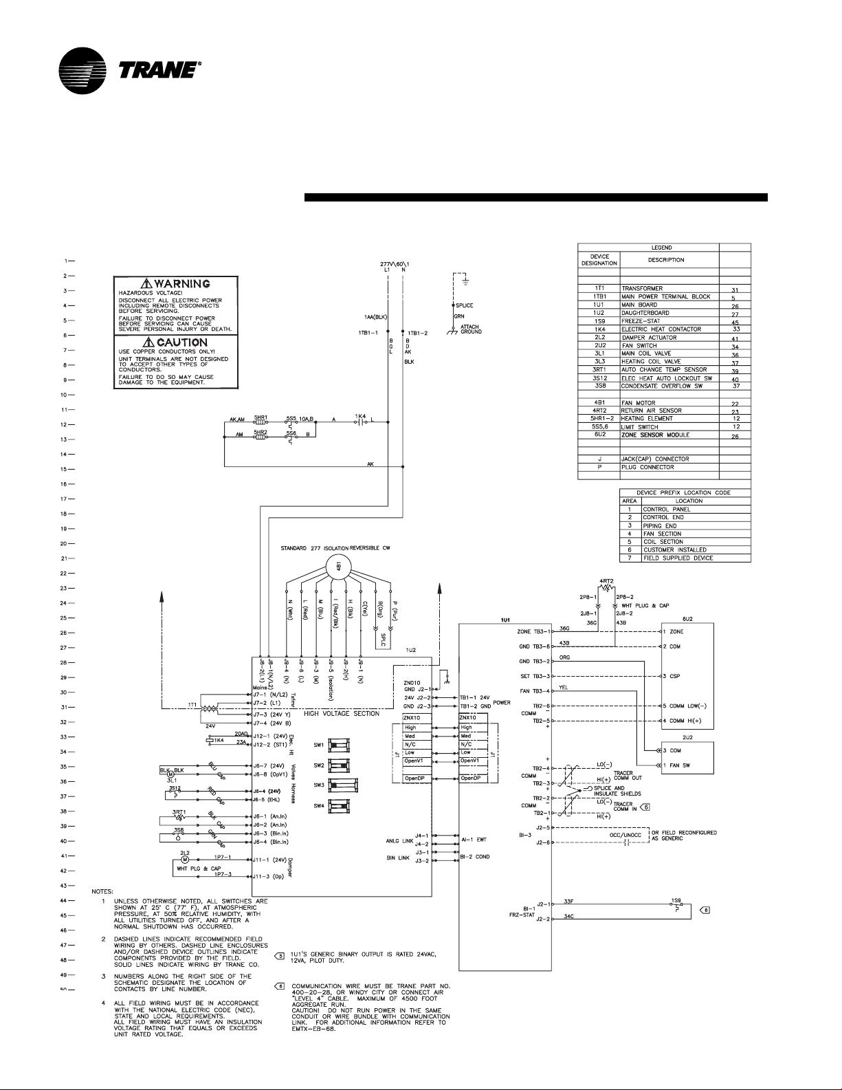
T racer ZN010 with electric heat
typical wiring
diagramMaintenance
74 UNT-SVX07A-EN
Page 75
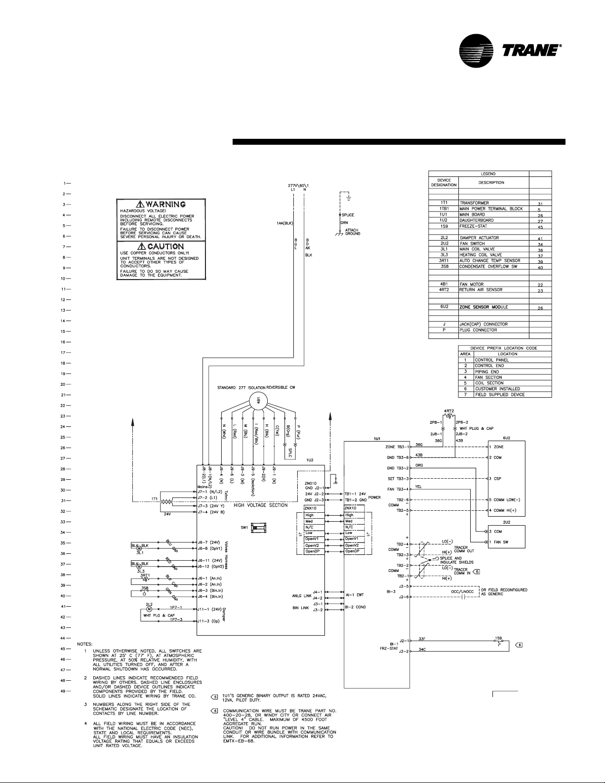
T racer ZN510 with main and auxilliary valves
typical wiring
diagramMaintenance
UNT-SVX07A-EN 75
Page 76

ZN520 with 2-stage electric heat
typical wiring
diagramMaintenance
76 UNT-SVX07A-EN
Page 77

Page 78

Page 79

Page 80

US
a business of American Standard Inc.
www.trane.com
For more information contact
your local office or e-mail us at
comfort@trane.com
Literature Order Number
File Number
Supersedes
Stocking Location
Trane has a policy of continuous product improvement and reserves the right to change design and specifications
without notice. Only qualified technicians should install and service equipment.
UNT-SVX07A-EN
PL-TD-UNT-SVX07A-EN 0405
UNT-IOM-6 04/00
LaCrosse - Inland
 Loading...