

Page 1

Installation, Operation, and
Maintenance
S&P Unit Heaters
Model Numbers:
UHSA
UHPA
May 2007 UH-SVX01A-EN
Page 2

Preface and Warnings and Cautions
Hazard Identification
Warnings and Cautions appear at
appropriate sections throughout this
literature. Read these carefully.
WARNING
Indicates a potentially hazardous
situation which, if not avoided, could
result in death or serious injury.
CAUTION
Indicates a potentially hazardous
situation which, if not avoided, may
result in minor or moderate injury. It
may also be used to alert against
unsafe practices.
CAUTION
Indicates a situation that may result
in equipment or property-damage
only accidents.
WARNING
Operational Hazards!
Improper installation, adjustment,
alteration, service or maintenance
can cause property damage, injury or
death. Read the installation,
operating and maintenance
instructions thoroughly before
installing or servicing this
equipment.
WARNING
Compliance Hazards!
Failure to comply with the general
safety information may result in
extensive property damage, severe
personal injury or death.
WARNING
Unit Alterations!
Do not alter the unit heater in any
way or damage to the unit and/or
severe personal injury or death may
occur!
WARNING
Voltage Hazard!
Disconnect all power supplies before
installing or servicing the heater. If
the power disconnect is out of sight,
lock it in the open position and tag it
to prevent unexpected application of
power. Failure to do so could result in
fatal electric shock, or severe
personal injury.
WARNING
Voltage Hazard!
Do not depend upon a thermostat or
other switch as sole means of
disconnecting power when installing
or servicing heater. Always
disconnect power at main circuit
breaker as described above. Failure
to do so could result in fatal electric
shock.
CAUTION
Equipment Damage!
Insure that all power sources
conform to the requirements of the
unit heater or damage to the unit will
result!
Follow installation instructions
CAREFULLY to avoid creating unsafe
conditions. All external wiring must
conform to applicable current local
codes, and to the latest edition of the
National Electric Code ANSI/NFPA
No. 70. In Canada, all external wiring
must conform to the Canadian
Electric Code, Part 1 CSA Standard
C22.1 All wiring should be done and
checked by a qualified electrician
using copper wire only. All steam
and hot water connections should be
made and leaktested by a suitably
qualified individual, per instructions
in this manual. Also follow
procedures listed on the “Unit
Equipment Start-Up Sheet” located
in this manual.
Make certain that the power source
conforms to the electrical
requirements of the heater.
Special attention must be given to
any grounding information
pertaining to this heater. To prevent
the risk of electrocution, the heater
must be securely and adequately
grounded. This should be
accomplished by connecting a
grounded conductor between the
service panel and the heater. To
ensure a proper ground, the
grounding means must be tested by
a qualified electrician.
Do not insert fingers or foreign
objects into the heater or its air
moving device. Do not block or
tamper with the heater in any
manner while in operation or just
after it has been turned off, as some
parts may be hot enough to cause
injury.
Note: To meet CSA and OSHA
requirements, units mounted
below 8 feet (2.4m) from the
floor must be equipped with
an OSHA fan guard.
It is good practice to have a shutoff
switch on the electrical power lines
controlling the heater. Whenever a
unit is serviced, shut power off to the
unit.
Since these units are installed in
most instances higher than 8 feet
(2.4m), proper type of ladders or
scaffolding should be used, as set up
by OSHA requirements. It is the
owner’s responsibility to provide any
scaffolding or other apparatus
required to perform emergency
service or annual/periodic
maintenance to this equipment.
In industrial plants, professional
maintenance crews should service
this equipment.
All Horizontal Unit Heaters are
shipped fully assembled and may be
used for steam or hot water
applications. Coils are factory tested
at 250 psig (1723.5 kg).
All Vertical Unit Heaters are shipped
fully assembled and may be used for
steam or hot water applications.
Coils are factory tested at 400 psig air
under water. Fans are balanced and
motors are prelubricated.
Unless otherwise specified, the
following conversions may be used
for calculating SI unit measurements:
1 foot = 0.305 m
1 inch = 25.4 mm
1 psig = 6.894 kPa
1 pound = 0.453 kg
1 gallon = 3.785 L
1 inch water column = 0.249 kPa
meter/second = FPM ÷ 196.8
liter/second = CFM x 0.472
1000 Btu per hour = 0.293 kW
1000 Btu/Cu. Ft. = 37.5 MJ/m
1 cubic foot = 0.028 m
3
3
© 2007 American Standard All Rights Reserved UH-SVX01A-EN
Page 3

Contents
Model Number Description . . . . . . . . . . . . . . . . . . . . . . . . . . . . . . . . . . . . . . . . . 4
Location . . . . . . . . . . . . . . . . . . . . . . . . . . . . . . . . . . . . . . . . . . . . . . . . . . . . . . . . . 6
Installation. . . . . . . . . . . . . . . . . . . . . . . . . . . . . . . . . . . . . . . . . . . . . . . . . . . . . . 13
Fan Guard/Louver Installation. . . . . . . . . . . . . . . . . . . . . . . . . . . . . . . . . . . . . . 21
Dimensional Data . . . . . . . . . . . . . . . . . . . . . . . . . . . . . . . . . . . . . . . . . . . . . . . . 23
Te c h n i c a l D a t a . . . . . . . . . . . . . . . . . . . . . . . . . . . . . . . . . . . . . . . . . . . . . . . . . . . 28
Options . . . . . . . . . . . . . . . . . . . . . . . . . . . . . . . . . . . . . . . . . . . . . . . . . . . . . . . . 30
Electrical Connections . . . . . . . . . . . . . . . . . . . . . . . . . . . . . . . . . . . . . . . . . . . . 32
Motor Data. . . . . . . . . . . . . . . . . . . . . . . . . . . . . . . . . . . . . . . . . . . . . . . . . . . . . . 38
Steam Performance Data . . . . . . . . . . . . . . . . . . . . . . . . . . . . . . . . . . . . . . . . . . 41
Hot Water Performance Data . . . . . . . . . . . . . . . . . . . . . . . . . . . . . . . . . . . . . . . 46
Maintenance . . . . . . . . . . . . . . . . . . . . . . . . . . . . . . . . . . . . . . . . . . . . . . . . . . . . 55
Warranty Info . . . . . . . . . . . . . . . . . . . . . . . . . . . . . . . . . . . . . . . . . . . . . . . . . . . . 57
UH-SVX01A-EN 3
Page 4

Model Number Description
UHSBA181TAA101A0A0A1
1234567891011121314151617181920
Description
Vertical hydronic unit heaters are
designed for installation requiring
down flow air delivery, offered in 15
sizes ranging from 41,300 to 705,000
BTU/Hr., and use with steam or hot
water. Low output (increased
airflow) units are available for high
ceiling applications.The designs are
certified by CSA (per CAN/CSA-C22.2
and UL1995). Do not alter these units
in any way and do not attach any
ductwork to these units. If you have
any questions after reading this
manual, contact the manufacturer.
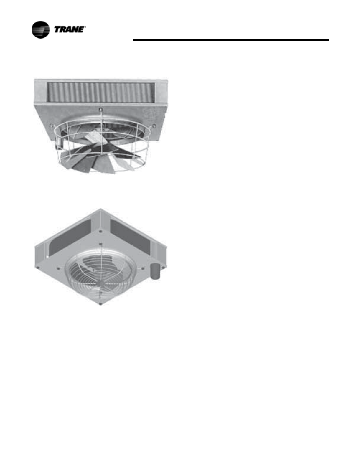
Figure 1. Vertical Unit (bottom)
Figure 2. Vertical Unit (top)
Horizontal hydronic unit heaters are
available in both serpentine and
header type units. Serpentine units
offer outputs from 8,030 to 35,900
BTU’s (2.4 to 10.5 kW) and are ideal
for hot water (only) installations with
limited clearances. Header type
horizontal units range from 18,000 to
360,000 (5.3 to 105.5 kW) and can
operate with either hot water or
steam. Both units are furnished with
totally enclosed motors, with
explosion proof motors as optional
on header types. The designs are
certified by CSA (per CAN/CSA-C22.2
and UL1995). Do not alter these
units in any way and do not
attach any ductwork to the
units. If you have any questions
after reading this manual, contact
the manufacturer.
Figure 3. Serpentine Type
Figure 4. Header Type
Service Model Number
Description
DIGIT 1,2,3 — PRODUCT TYPE
UHP
UHS
DIGIT 4— DEVELOPMENT
SEQUENCE
B
DIGIT 5, 6, 7—CAPACITY/COIL
TYPE
Hot Water Only (Coil Type A
"Serpentine")
A08 8,030 BTU/HR
A18 18,400 BTU/HR
A25 24,800 BTU/HR
A36 35,900 BTU/HR
Steam or Hot Water
042 41,300 BTU/HR
064 65,500 BTU/HR
080 80,600 BTU/HR
102 101,80 0 BTU/HR
122 124,400 BTU/HR
146 152,000 BTU/HR
166 173,000 BTU/HR
202 210,200 BTU/HR
252 249,800 BTU/HR
280 283,800 BTU/HR
336 333,400 BTU/HR
384 386,000 BTU/HR
500 496,000 BTU/HR
600 585,000 BTU/HR
720 705,000 BTU/HR
Steam or Hot Water "Header
Type Coil"
018 18,0 0 0 BTU/HR
024 24,000 BTU/HR
036 36,000 BTU/HR
048 48,000 BTU/HR
060 60,000 BTU/HR
072 72,000 BTU/HR
084 84,000 BTU/HR
096 96,000 BTU/HR
108 108,000 BTU/HR
120 120,000 BTU/HR
132 132,000 BTU/HR
144 144,000 BTU/HR
156 156,000 BTU/HR
4 UH-SVX01A-EN
Page 5

Model Number Description
180 180,000 BTU/HR
204 204,000 BTU/HR
240 240,000 BTU/HR
280 280,000 BTU/HR
300 300,000 BTU/HR
360 360,000 BTU/HR
DIGIT 8—VOLTAGE
1 115/1/60
3 230/1/60 (115 V motor with
Transformer)
4 208/3/60
5 230/3/60
6 460/3/60
7 575/60/3 (Totally Enclosed)
(P only)
DIGIT 9 - MOTOR TYPE
T Totally Enclosed
E Explosion Proof
DIGIT 10- DESIGN SEQUENCE
A
DIGIT 11- TUBE MATERIAL
A Copper
B Steel (P only)
DIGIT 17 - Manual Starter
0None
AManual Starter
DIGIT 18 - STEAM & HOT WATER
CONTROL
0None
1 Strap on Hot Water Control
2 Steam Pressure Control (Open
on rise in pressure)
3 Steam Pressure Control
(Close on rise in pressure)
4 5.0 Amp Speed Control
Switch ( Capacities 18 - 108
only)
DIGIT 19 - VERTICAL LOUVER
0None
A Vertical Louver
B Fin Diffuser (P only)
C Fin Diffuser w/ Coating (Ponly)
DIGIT 12- FAN GUARD
1 OSHA Fan Guard
2 Standard Fan Guard (3 phase
or Explosion Proof motors
only)
3 Standard Fan Guard (Unit
Capacities 240 - 360)
DIGIT 13 - SPECIAL COATING
0 No Special Coating
A Phenolic Coating (Baked)
BEpoxy
C Epoxy Phenolic
DIGIT 14 - DISCONNECT SWITCH
0None
1 Disconnect switch
DIGIT 15 - THERMOSTATS (LINE
VOLTAGE)
0None
A Light Duty TSTAT w/ subbase
Line Volts 8 Amps
B Heavy Duty TSTAT w/
subbase&guard Line Volts 16
Amps+A32
DIGIT 16 - THERMOSTAT COVER
0None
A Locking Thermostat Cover
UH-SVX01A-EN 5
Page 6
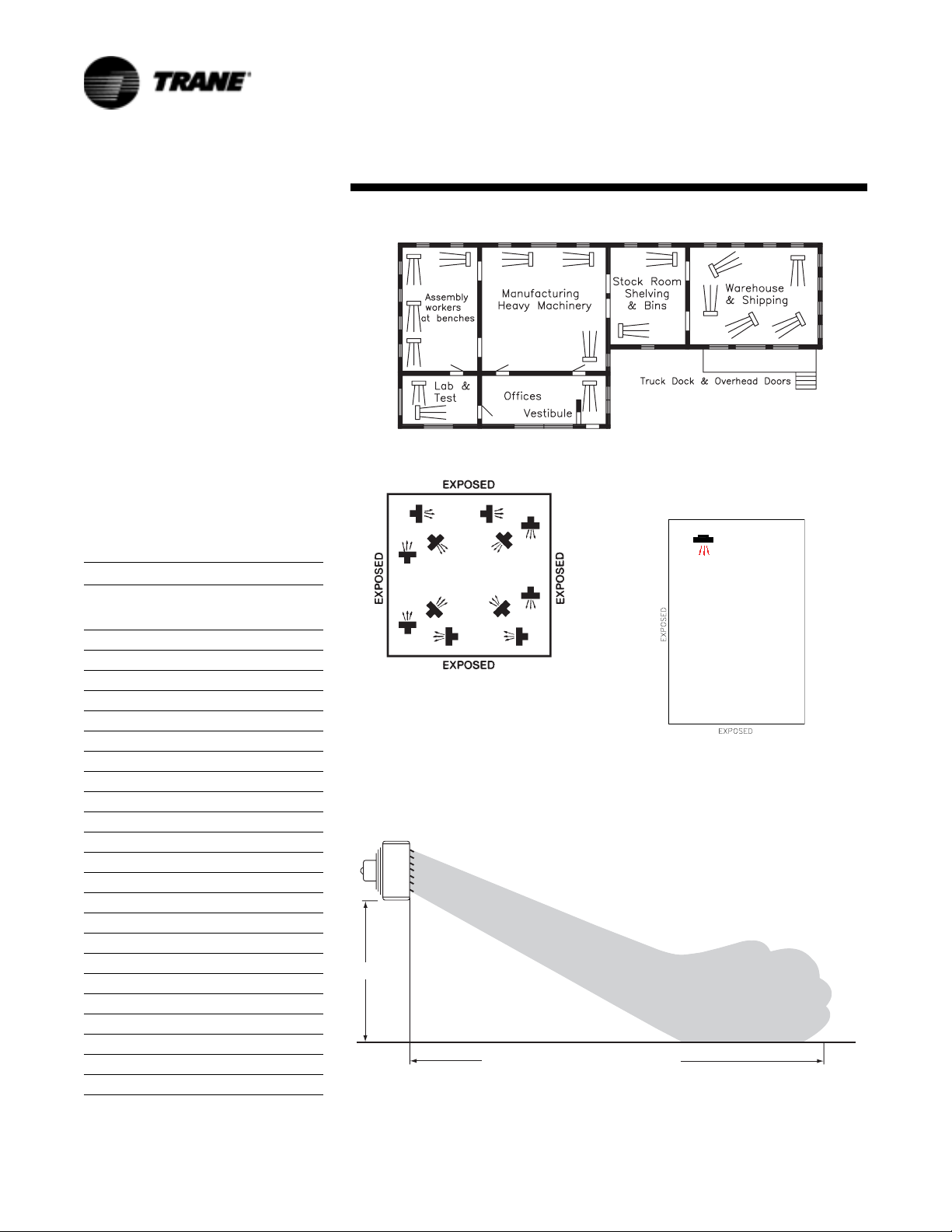
It is assumed that the design
engineer has selected, sized, and
located in the area to be heated.
However, the information given here
may be of additional help to the
installer. These sketches indicate
suggested basic locations for
different types of unit heaters.
Horizontal unit heaters should be
located to give a circulatory motion,
preferably in the outer perimeter of
the building. The units should be
spaced to properly blanket the areas
with warm air.
The unit should be suspended from
connections provided in the unit by
means of rods. The rods should then
be attached to solid supports of the
building.
Ta b l e 1.
Model
No
A08 8 (2.4) 20 (6.1)
A18 8 (2.4) 25 (7.6)
A25 9 (2.7) 29 (8.8)
A36 9 (2.7) 29 (8.8)
108 11 (3.4) 40 (12.2)
120 12 (3.7) 40 (12.2)
132 13 (4.0) 54 (16.5)
144 13 (4.0) 55 (16.8)
156 13 (4.0) 55 (16.8)
180 13 (4.0) 53 (16.2)
204 13 (4.0) 55 (16.8)
240 14 (4.3) 57 (17.4)
280 14 (4.3) 57 (17.4)
300 15 (4.6) 58 (17.7)
360 15 (4.6) 60 (18.3)
Maximum
Mounting HT.
ft (m)
18 8 (2.4) 20 (6.1)
24 8 (2.4) 24 (7.3)
36 9 (2.7) 28 (8.5)
48 9 (2.7) 30 (9.1)
60 10 (3.0) 30 (9.1)
72 10 (3.0) 29 (8.8)
84 10 (3.0) 30 (9.1)
96 11 (3.4) 38 (11.6)
Approx. Max.
Throw ft (m)
Location
Figure 5.
A narrow area with four exposed
walls either with or without roof
exposure.
Figure 6.
Figure 6 represents a large square
area with exposed walls and roof;
units are blanketing all exposed
surfaces.
Figure 7 is based on 2 PSI (13.8 kPa)
steam pressure and 60 °F (16 °C)
entering air temperature.
H
MAXIMUM DISTANCE OF THROW = T
Figure 7. Mounting Height and Approx. Heat Throw
Figure 8.
A small area with exposed walls
requiring one unit.
6 UH-SVX01A-EN
Page 7
Location
A
BC
UNIT SIZE
048/060
072
084 & 120
096/108
1-3/4
C
132/144/156
180/204
240/280
300/360
A
15-5/16
16-9/16
19-1/16
17-13/16
21-9/16
22-13/16
26-1/16
31-9/16
1-7/8
2-1/2
3"
2-1/2
3-1/2
4"
4-1/2
11-11/16
10"
6"
1"
BB
C
L
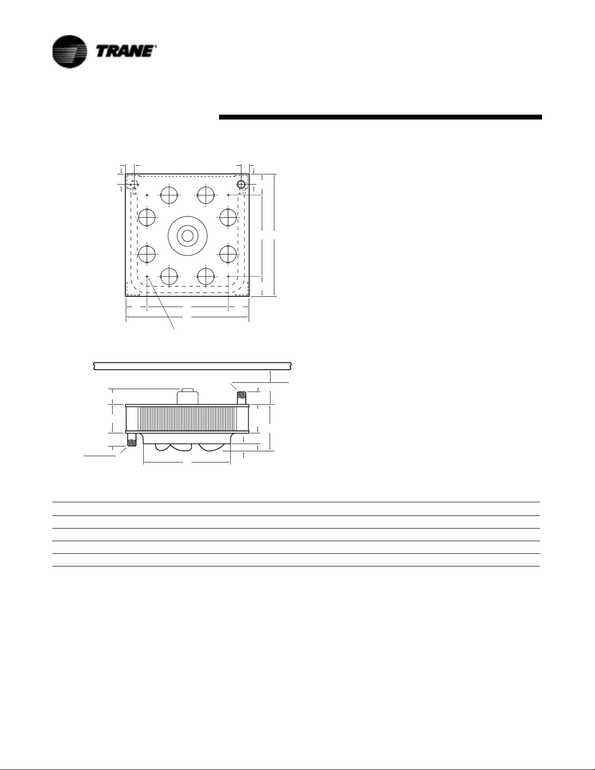
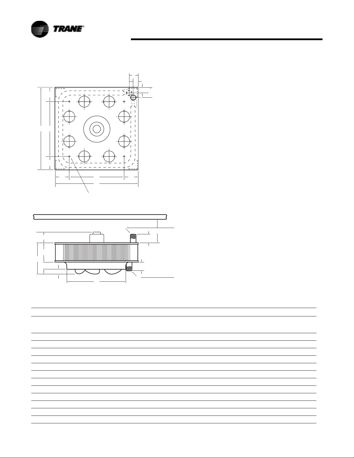
Figure 9. Four Point Suspension-Shelf Mounted Motors Only
C
1-3/4
4 PT. SUSPENSION
USE 3/8-16
THREADED RODS
(4 LOCATIONS)
C
L
D6340
UH-SVX01A-EN 7
Page 8
Location
"FORCED HOT WATER"
PET COCK
(SYSTEM VENT)
GATE VALVE
RETURN
Figure 10. Forced Hot Water
SUPPLY
GATE VALVE
D-6056
DRAIN VALVE
8 UH-SVX01A-EN
Page 9
Location
PET COCK
(SYSTEM VENT)
RETURN
GATE VALVE
"FORCED HOT WATER"
(Serpentine Units)
Figure 11. Forced Hot Water: Serpentine Unit Only
SUPPLY
GATE VALVE
DRAIN VALVE
D-6057
UH-SVX01A-EN 9
Page 10
Location
GATE VALVE
"HIGH PRESSURE STEAM"
SUPPLY
PITCH UP
RETURN
GATE VALVE
PITCH UP
PET COCK
D-6058
BUCKET TRAP
(WITH AIR BYPASS)
Figure 12. High Pressure Steam
10 UH-SVX01A-EN
STRAINER
Page 11
Location
"LOW PRESSURE STEAM GRAVITY"
SUPPLY
GATE VALVE
PITCH UP
RETURN
AIR VENT
PITCH UP
GATE VALVE
CHECK VALVE
Figure 13. Low Pressure Steam Gravity
UH-SVX01A-EN 11
MIN. SIZE 3/4
D-6059
10" MIN. (254 MM)
Page 12
Location
GATE VALVE
"LOW PRESSURE
VAPOR OR VACUUM"
SUPPLY
PITCH UP
RETURN
GATE VALVE
PITCH UP
D-6060
F & T TRAP
Figure 14. Low Pressure Vapor Or Vacuum
12 UH-SVX01A-EN
STRAINER
Page 13
Installation
Installation: P Type
Periodic Service
WARNING
Heavy Objects!
Ensure that all hardware used in the
suspension of each unit heater is
more than adequate for the job.
Failure to do so may result in
extensive property damage, severe
personal injury or death.
CAUTION
Lifting/Suspension Methods!
Make certain that the lifting
methods used to lift the heater and
the method of suspension used in
the field installation of the heater are
capable of uniformly supporting the
weight of the heater at all times.
Failure to heed this warning may
result in property damage or
personal injury!
CAUTION
Structural Integrity!
Make certain that the structure to
which the heater is mounted is
capable of supporting its weight.
Under no circumstances must the
piping or the electrical conduit be
used to support the heater; or
should any other objects (i.e. ladder,
person) lean against the heater or
the electrical conduit for support.
CAUTION
Performance Failure!
Unit heaters must be hung level
from side to side and from front to
back. Failure to do so will result in
poor performance and or premature
failure of the unit.
It is assumed that the design
engineer has selected, sized, and
located in the area to be heated by
the design engineer. However, the
information given here may be of
additional help to the installer.
Vertical unit heaters should be
located to give spot heating or a
circulatory distribution, preferably
near the outer perimeter of the
building. The units should be spaced
to properly blanket the areas with
warm air. Place the units at points of
greatest heat loss. Blanket outside
doorway and provide ample
coverage of window areas. Keep
units away from obstructions that
will impede the full and natural air
delivery of the units.
Install unit heaters to meet CSA and
OSHA requirements; Vertical Unit
Heaters mounted lower than 2.4
meters (8 feet) from the floor must
be equipped with an OSHA fan
guard. Weldnuts are provided at the
top of all units for suspension
purposes. The unit should be
suspended from connections
provided in the unit by means of
rods. The rods should then be
attached to solid supports of the
building.
Units must hang level vertically and
horizontally.
Provide sufficient clearance around
units for maintenance purposes. This
includes at least 7 inches above all
Vertical Unit Heaters even though
the motor is removable through the
bottom.
Isolators are not required but may be
desirable for some applications.
Refer to Table 2 for Unit Weights.
Table 2. Unit Weights-Lbs
Vertical Unit Heaters
Unit Weights (Lbs.)
042 26
064 32
080 36
102 51
122 54
146 69
166 69
202 75
252 115
280 120
336 120
384 126
500 267
600 210
720 260
EXAMPLE
Tabl e 4 lists maximum mounting
height and floor spread data of warm
air coverage at floor level with louver
cone diffusers. Correction factors for
various water temp. and psig of
steam are in Ta b l e 7.
An approximation of the floor spread
when operating on other than 2 lb.
Steam or 219 degree may be
obtained by ratioing the new floor
spread and the maximum mounting
height to that at 2 lb. steam or 219
degree hot water.
Following is an example:
Determine the floor spread and the
maximum mounting height of a std.
model 80 unit heater with a cone
diffuser set at 90 degrees, operating
on 280 degree hot water.
From Ta b l e 6 , maximum mounting
height of a model 80 at 219 degree
hot water is 18.5 ft. with floor
coverage of 14.0 ft. diameter. The
maximum mounting height
correction factor at 280 degree hot
water is 0.80.
18.5 ft. x 0.80 = 14.8 ft.
Maximum mounting height of a
model 80 using 280 degree hot
water.
“X” = floor spread of model 80 using
280 degree hot water.
X = 14.8 x 14.0 / 18.5
X = 207.2 / 18.5
X = 11.2 ft.
UH-SVX01A-EN 13
Page 14
Installation
Table 3. Maximum Mounting Height in Feet with and without Louver Cone Diffuser
Unit Size Steam Pressure (PSI) Unit Size Steam Pressure (PSI)
042
042*
042L
042L*
064
064*
064L
064L*
080
080*
2
(13.8)5(34.5)10(68.9)50(344.7)75(517.1)
10.5
(3.2)
12.5
(3.8)
7.5
(2.3)
9.0
(2.7)
12.5
(3.8)
14.5
(4.4)
9.0
(2.7)
10.5
(3.2)
12.0
(3.7)
14.5
(4.4)
9.5
(2.9)
11.5
(3.5)
15.0
(4.6)
19.0
(5.8)
11.5
(3.5)
14.0
(4.3)
15.0
(4.6)
18.5
(5.6)
11.0
(3.4)
13.5
(4.1)
10.0
(3.0)
12.0
(3.7)
7.5
(2.3)
8.5
(2.6)
12.0
(3.7)
14.0
(4.3)
8.5
(2.6)
10.0
(3.0)
11.5
(3.5)
14.0
(4.3)
9.0
(2.7)
11.0
(3.4)
14.5
(4.4)
18.5
(5.6)
11.0
(3.4)
13.5
(4.1)
14.5
(4.4)
18.0
(5.5)
10.5
(3.2)
13.0
(4.0)
10.0
(3.0)
12.0
(3.7)
7.5
(2.3)
8.5
(2.6)
12.0
(3.7)
13.5
(4.1)
8.5
(2.6)
10.0
(3.0)
11.5
(3.5)
14.0
(4.3)
9.0
(2.7)
11.0
(3.4)
14.5
(4.4)
18.5
(5.6)
11.0
(3.4)
13.5
(4.1)
14.0
(4.3)
17.5
(5.3)
10.5
(3.2)
13.0
(4.0)
9.0
(2.7)
11.0
(3.4)
7.5
(2.3)
7.5
(2.3)
10.5
(3.2)
12.0
(3.7)
7.5
(2.3)
9.0
(2.7)
10.0
(3.0)
12.0
(3.7)
8.0
(2.4)
9.5
(2.9)
12.5
(3.8)
16.5
(5.0)
9.5
(2.9)
12.0
(3.7)
12.0
(3.7)
15.5
(4.7)
9.0
(2.7)
11.5
(3.5)
8.0
(2.4)
10.0
(3.0)
7.5
(2.3)
7.5
(2.3)
9.5
(2.9)
11.5
(3.5)
7.5
(2.3)
8.5
(2.6)
9.5
(2.9)
11.5
(3.5)
8.0
(2.4)
9.0
(2.7)
12.0
(3.7)
16.0
(4.9)
9.0
(2.7)
11.5
(3.5)
11.5
(3.5)
15.0
(4.6)
8.5
(2.6)
11.0
(3.4)
080L
080L*
102
102*
102L
102L*
122
122L
146
146L
2
(13.8)5(34.5)10(68.9)50(344.7)75(517.1)
18.0
(5.5)
22.0
(6.7)
13.0
(4.0)
17.0
(5.2)
14.0
(4.3)
17.0
(5.2)
11.0
(3.4)
13.5
(4.1)
17.5
(5.3)
21.5
(6.6)
15.0
(4.6)
18.5
(5.6)
16.0
(4.9)
19.5
(5.9)
21.0
(6.4)
26.0
(7.9)
15.5
(4.7)
19.0
(5.8)
18.0
(5.5)
22.5
(6.9)
17.5
(5.3)
21.0
(6.4)
12.5
(3.8)
16.5
(5.0)
13.5
(4.1)
16.5
(5.0)
10.5
(3.2)
13.0
(4.0)
17.0
(5.2)
21.0
(6.4)
14.5
(4.4)
18.0
(5.5)
15.5
(4.7)
19.0
(5.8)
20.5
(6.2)
25.5
(7.8)
15.0
(4.6)
18.5
(5.6)
17.5
(5.3)
22.0
(6.7)
17.5
(5.3)
21.0
(6.4)
12.0
(3.7)
16.0
(4.9)
13.0
(4.0)
16.0
(4.9)
10.5
(3.2)
13.0
(4.0)
16.5
(5.0)
20.5
(6.2)
14.5
(4.4)
18.0
(5.5)
15.5
(4.7)
18.5
(5.6)
20.0
(6.1)
25.0
(7.6)
14.5
(4.4)
18.0
(5.5)
17.5
(5.3)
21.5
(6.6)
15.0
(4.6)
19.0
(5.8)
11.0
(3.4)
14.0
(4.3)
11.5
(3.5)
14.0
(4.3)
9.5
(2.9)
12.0
(3.7)
15.0
(4.6)
18.5
(5.6)
13.0
(4.0)
16.0
(4.9)
14.0
(4.3)
17.0
(5.2)
17.5
(5.3)
22.5
(6.9)
13.0
(4.0)
16.0
(4.9)
15.0
(4.6)
18.5
(5.6)
14.0
(4.3)
18.0
(5.5)
10.5
(3.2)
13.5
(4.1)
11.0
(3.4)
13.5
(4.1)
9.0
(2.7)
11.5
(3.5)
14.5
(4.4)
17.5
(5.3)
12.5
(3.8)
15.0
(4.6)
13.5
(4.1)
16.0
(4.9)
17.0
(5.2)
21.5
(6.6)
12.0
(3.7)
15.5
(4.7)
14.0
(4.3)
18.0
(5.5)
NOTES:
* = Low Speed
L = Low output model with all air ports open
Figures in bold face show maximum mounting height with louver cone diffusers set vertically.
Above table based on 60°F entering air temperature. In providing for the use of diffusers, it must be remembered that adjustment of a LCD to deflect air
toward horizontal immediately lowers the mounting height limit.
14 UH-SVX01A-EN
Page 15
Installation
Table 4. Maximum Mounting Height in Feet with and without Louver Cone Diffuser
Steam Pressure (PSI)
Unit Size
166
166L
202
202L
252
252L
280
280L
336
2
(13.8)5(34.5)10(68.9)50(344.7)75(517.1)
18.0
(5.5)
22.5
(6.9)
22.0
(6.7)
27.5
(8.4)
22.0
(6.7)
27.5
(8.4)
25.5
(7.8)
31.5
(9.6)
20.0
(6.1)
25.0
(7.6)
24.0
(7.3)
29.5
(9.0)
21.0
(6.4)
26.0
(7.9)
25.5
(7.8)
32.0
(9.8)
24.0
(7.3)
30.0
(9.1)
17.5
(5.3)
22.0
(6.7)
21.5
(6.6)
27.0
(8.2)
21.5
(6.6)
27.0
(8.2)
25.0
(7.6)
31.0
(9.4)
19.5
(5.9)
24.0
(7.3)
23.5
(7.2)
28.5
(8.7)
20.5
(6.2)
25.5
(7.8)
25.0
(7.6)
31.0
(9.4)
23.0
(7.0)
29.0
(8.8)
17.0
(5.2)
21.5
(6.6)
21.0
(6.4)
26.5
(8.1)
21.0
(6.4)
26.5
(8.1)
24.5
(7.5)
30.5
(9.3)
19.0
(5.8)
23.5
(7.2)
23.0
(7.0)
28.0
(8.5)
20.0
(6.1)
25.0
(7.6)
24.5
(7.5)
30.0
(9.1)
22.0
(6.7)
28.0
(8.5)
14.5
(4.4)
19.0
(5.8)
18.5
(5.6)
23.5
(7.2)
18.5
(5.6)
24.0
(7.3)
22.0
(6.7)
27.0
(8.2)
17.0
(5.2)
20.5
(6.2)
20.0
(6.1)
24.5
(7.5)
17.5
(5.3)
22.0
(6.7)
21.0
(6.4)
26.0
(7.9)
20.0
(6.1)
25.0
(7.6)
14.0
(4.3)
18.0
(5.5)
17.5
(5.3)
22.5
(6.9)
17.5
(5.3)
23.0
(7.0)
21.0
(6.4)
26.0
(7.9)
16.0
(4.9)
19.5
(5.9)
19.0
(5.8)
23.5
(7.2)
17.0
(5.2)
21.0
(6.4)
20.0
(6.1)
25.0
(7.6)
19.0
(5.8)
24.0
(7.3)
Unit Size
336L
384
384L
500
500L
600
600L
720
720L
2
(13.8)5(34.5)10(68.9)50(344.7)75(517.1)
29.0
(8.8)
36.0
(11.0)
28.5
(8.7)
35.5
(10.8)
32.5
(9.9)
41.0
(12.5)
29.5
(9.0)
36.5
(11.1)
35.0
(10.7)
43.5
(13.3)
34.0
(10.4)
42.5
(13.0)
37.0
(11.3)
46.5
(14.2)
38.5
(11.7)
48.0
(14.6)
42.5
(13.0)
53.0
(16.2)
Steam Pressure (PSI)
28.5
(8.7)
35.0
(10.7)
28.0
(8.5)
35.0
(10.7)
31.5
(9.6)
40.0
(12.2)
29.0
(8.8)
36.0
(11.0)
34.0
(10.4)
42.5
(13.0)
33.0
(10.1)
41.5
(12.6)
36.0
(11.0)
45.5
(13.9)
37.5
(11.4)
47.0
(14.3)
41.5
(12.6)
52.0
(15.8)
28.0
(8.5)
34.0
(10.4)
27.5
(8.4)
34.0
(10.4)
30.5
(9.3)
39.0
(11.9)
28.5
(8.7)
35.5
(10.8)
33.0
(10.1)
41.5
(12.6)
32.0
(9.8)
40.5
(12.3)
35.0
(10.7)
44.5
(13.6)
36.5
(11.1)
46.0
(14.0)
40.5
(12.3)
51.0
(15.5)
25.0
(7.6)
30.0
(9.1)
24.0
(7.3)
30.0
(9.1)
27.5
(8.4)
35.0
(10.7)
25.0
(7.6)
32.0
(9.8)
29.0
(8.8)
35.0
(10.7)
28.0
(8.5)
36.0
(11.0)
31.0
(9.4)
39.0
(11.9)
32.0
(9.8)
40.0
(12.2)
35.0
(10.7)
44.0
(13.4)
24.0
(7.3)
29.0
(8.8)
23.0
(7.0)
29.0
(8.8)
26.5
(8.1)
33.5
(10.2)
24.0
(7.3)
30.5
(9.3)
28.0
(8.5)
34.0
(10.4)
27.0
(8.2)
34.5
(10.5)
30.0
(9.1)
37.0
(11.3)
30.5
(9.3)
39.0
(11.9)
33.5
(10.2)
42.0
(12.8)
NOTES:
* = Low Speed
L = Low output model with all air ports open
Figures in bold face show maximum mounting height with louver cone diffusers set vertically.
Above table based on 60°F entering air temperature. In providing for the use of diffusers, it must be remembered that adjustment of a LCD to deflect air
toward horizontal immediately lowers the mounting height limit.
Table 5. Maximum Spread
MODEL No. 42 64 80 102 122 146 166 202 252 280 336 384 500 600 720
Spread ft (m) 15
Note: The "spread" is the diameter of the comfort zone at floor level. The above table represents the spread for standard units without a louver cone
diffuser and mounted at its maximum height at 2 psi (13.8 kPa) steam pressure and 60°F (16*C) entering air. (See Tables 21 and 22 for maximum moun
ing heights.)
(4.6)17(5.2)20(6.1)24(7.3)26(7.9)27(8.2)28(8.5)32(9.8)35(10.7)37(11.3)45(13.7)50(15.2)54(16.5)57(17.4)60(18.3)
UH-SVX01A-EN 15
Page 16

Installation
Table 6. Maximum Mounting Height and Diameter at Floor (Based on 60°F EAT and 219°F EWT or 2 psig steam)
Diffuser Cone 90°
See Figure 5A
Standard Low Output Standard Low Output
HDH D H D H D
Model ft (m) ft (m) ft (m) ft (m) ft (m) ft (m) ft (m) ft (m)
42 12.5
64 14.5
80 18.5
102 17.0
122 19.5
146 19.0
166 22.5
202 27.5
252 25.0
280 26.0
336 30.0
384 35.5
500 36.5
600 42.5
720 48.0
(3.8)
(4.4)
(5.6)
(5.2)
(5.9)
(5.8)
(6.9)
(8.4)
(7.6)
(7.9)
(9.1)
(10.8)
(11.1)
(13.0)
(14.6)
11.0
(3.4)
12.0
(3.7)
14.0
(4.3)
18.0
(5.5)
19.0
(5.8)
20.0
(6.1)
21.0
(6.4)
25.0
(7.6)
27.0
(8.2)
29.0
(8.8)
34.0
(10.4)
39.0
(11.9)
42.0
(12.8)
45.0
(13.7)
46.0
(14.0)
14.5
(4.4)
19.0
(5.8)
22.0
(6.7)
21.5
(6.6)
26.0
(7.9)
22.5
(6.9)
27.5
(8.4)
31.5
(9.6)
29.5
(9.0)
32.0
(9.8)
36.0
(11.0)
41.0
(12.5)
43.5
(13.3)
46.5
(14.2)
53.0
(16.2)
16.0
(4.9)
19.0
(5.8)
23.0
(7.0)
26.0
(7.9)
29.0
(8.8)
30.0
(9.1)
31.0
(9.4)
35.0
(10.7)
38.0
(11.6)
40.0
(12.2)
47.0
(14.3)
52.0
(15.8)
57.0
(17.4)
60.0
(18.3)
63.0
(19.2)
9.0
(2.7)
10.0
(3.0)
12.5
(3.8)
11.0
(3.4)
13.0
(4.0)
12.0
(3.7)
13.0
(4.0)
14.0
(4.3)
13.0
(4.0)
15.0
(4.6)
18.0
(5.5)
20.0
(6.1)
24.0
(7.3)
26.0
(7.9)
28.0
(8.5)
Diffuser Cone 45°
See Figure 5B
20.0
(6.1)
24.0
(7.3)
26.0
(7.9)
31.0
(9.4)
33.0
(10.1)
39.0
(11.9)
42.0
(12.8)
45.0
(13.7)
47.0
(14.3)
50.0
(15.2)
55.0
(16.8)
59.0
(18.0)
65.0
(19.8)
70.0
(21.3)
75.0
(22.9)
11.0
(3.4)
12.0
(3.7)
15.0
(4.6)
14.0
(4.3)
16.0
(4.9)
15.5
(4.7)
18.0
(5.5)
21.0
(6.4)
19.0
(5.8)
21.0
(6.4)
24.0
(7.3)
28.0
(8.5)
30.0
(9.1)
34.0
(10.4)
38.0
(11.6)
25.0
(7.6)
29.0
(8.8)
31.0
(9.4)
35.0
(10.7)
38.0
(11.6)
44.0
(13.4)
48.0
(14.6)
53.0
(16.2)
55.0
(16.8)
60.0
(18.3)
66.0
(20.1)
71.0
(21.6)
76.0
(23.2)
78.0
(23.8)
87.0
(26.5)
16 UH-SVX01A-EN
Page 17

Installation
Figure 15.
Notes: To meet OSHA requirements, units mounted lower than 8 feet from the floor must be equipped with an OSHA fan guard.
Table 7. Mounting Height Correction Factors
Water °F 150 160 170 180 190 200
Temperature (°C) (66) (71) (77) (82) (88) (93)
Steam PSI - - - - - -
Pressure (kPa) - - - - - -
Correction Factor 1.32 1.27 1.23 1.18 1.14 1.09
Water °F 210 219 227 239 250 259
Temperature (°C) (99) (104) (108) (115) (121) (126)
Steam PSI - 2 5 10 15 20
Pressure (kPa) - (13.8) (34.5) (68.9) (103.4) (137.9)
Correction Factor 1.05 1.00 0.97 0.94 0.89 0.86
Water °F 267 280 287 298 307 320
Temperature (°C) (131) (138) (142) (148) (153) (160)
Steam PSI 25 35 40 50 60 75
Pressure (kPa) (172.4) (241.3) (275.8) (344.7) (413.6) (517.1)
Correction Factor 0.83 0.80 0.76 0.73 0.70 0.69
UH-SVX01A-EN 17
Page 18
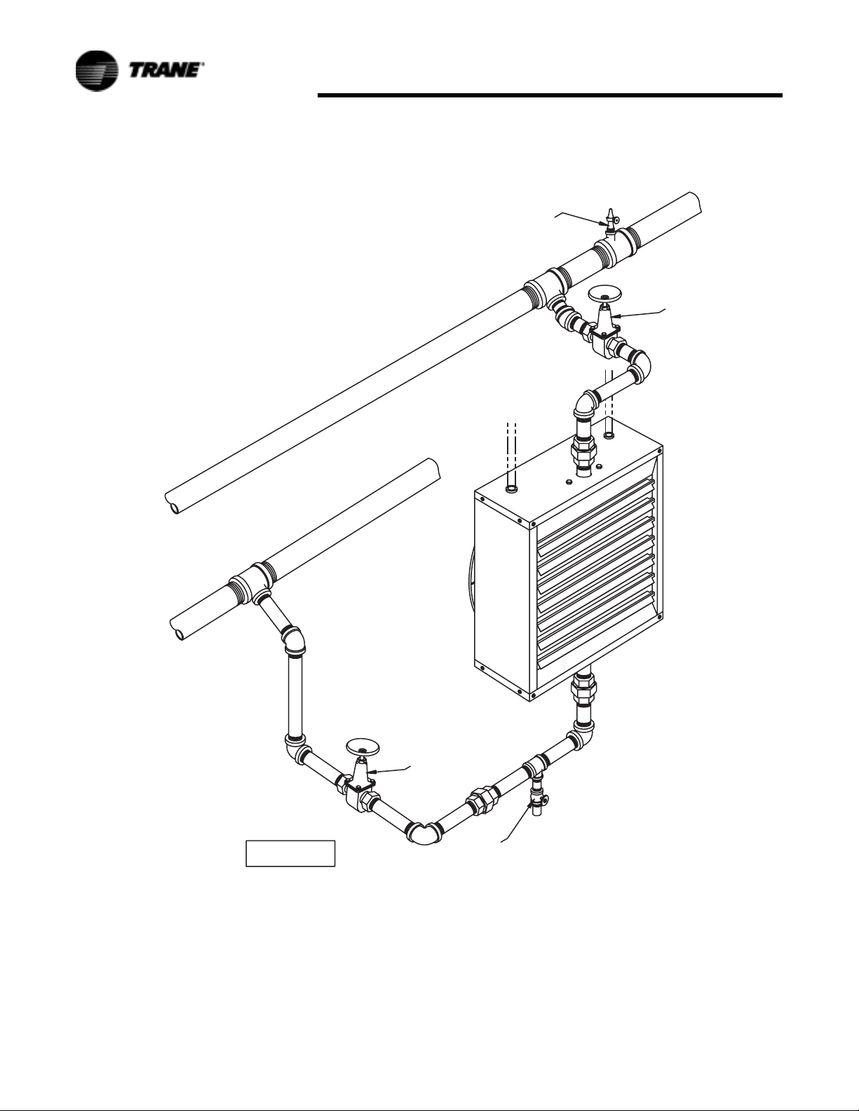
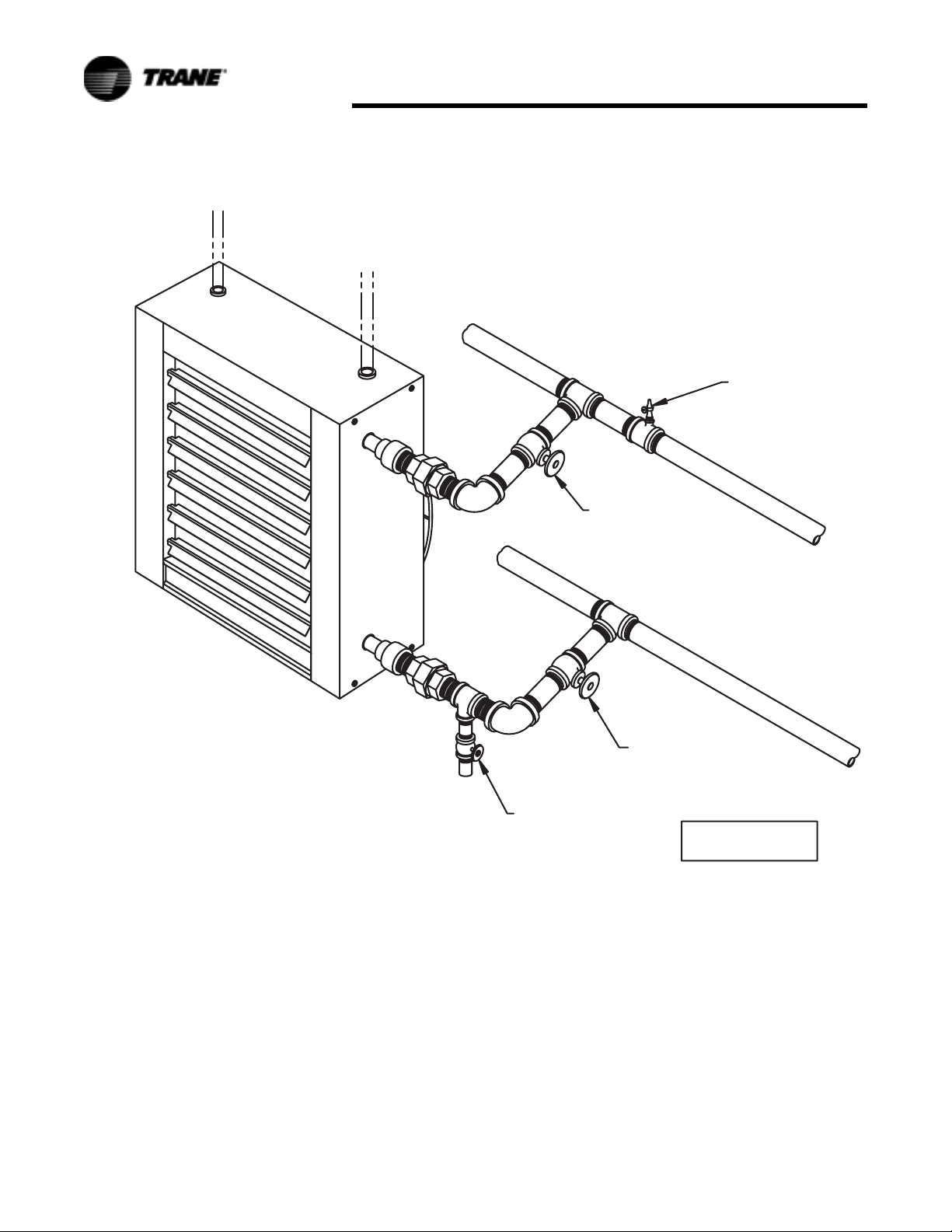
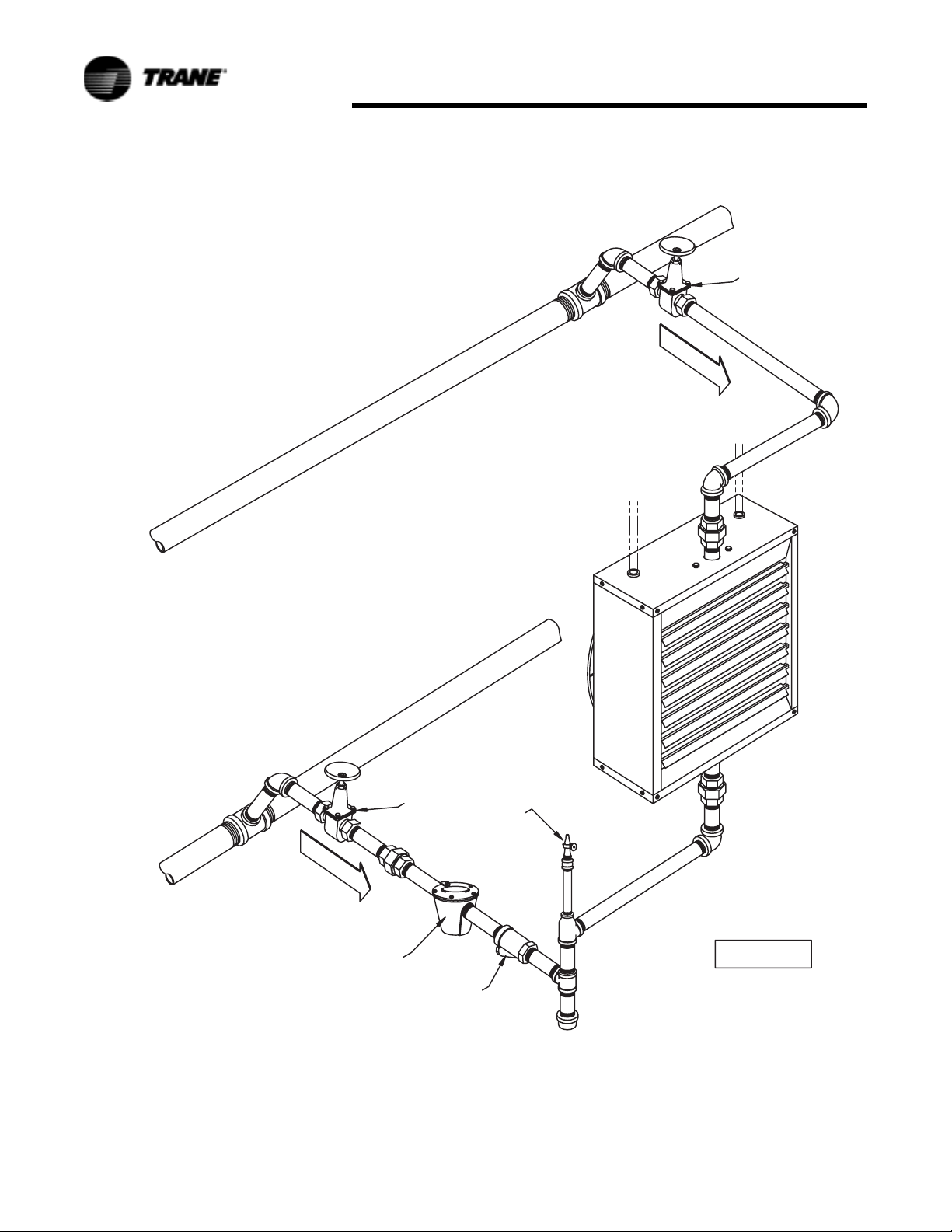
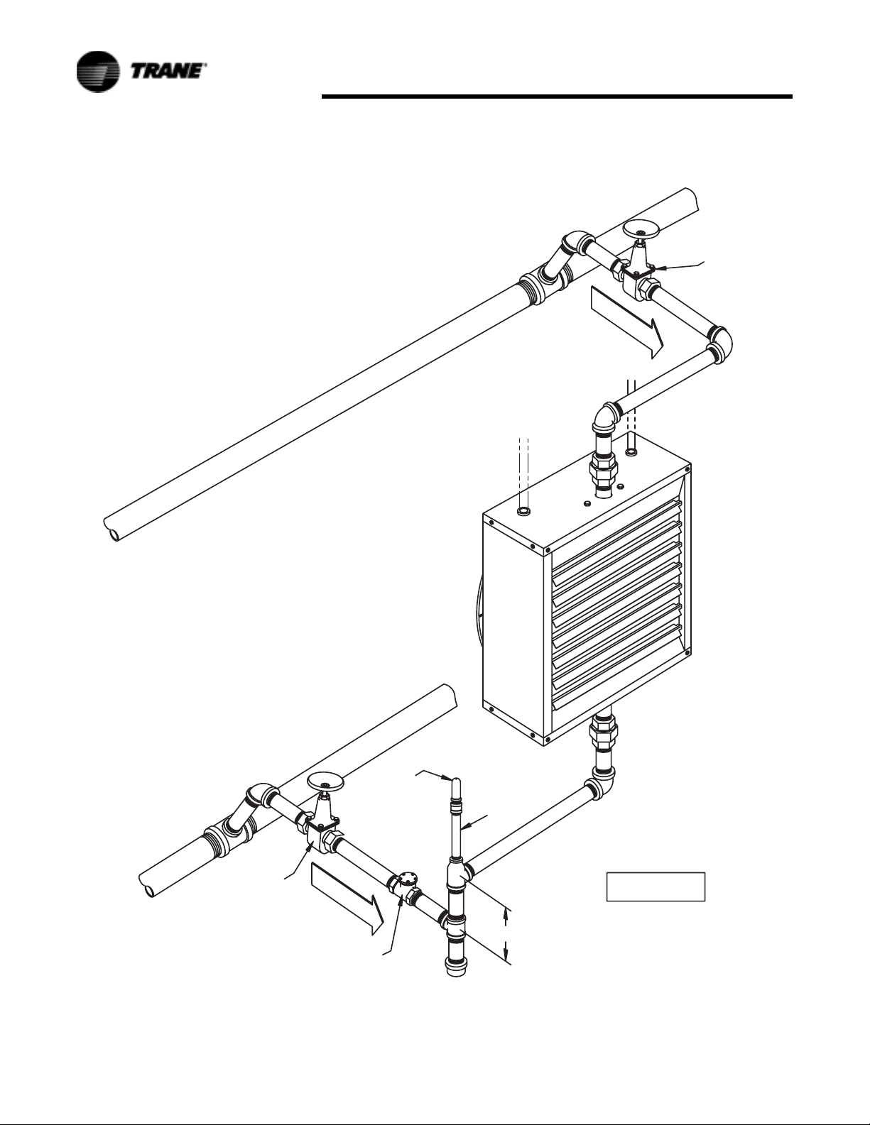
Piping
To provide proper coil operation,
follow all piping recommendations
listed in this manual.
Threaded pipe headers are provided
on all Vertical Units for piping
connections. See Figure 25.
Connections are given in Figure 18
and Figure 19 and Table 27 and
Table 28.
Follow standard practices and codes
when installing the piping. Provide
swing joints for expansion purposes,
unions and shut-off valves for
servicing purposes and as illustrated
in Figure 6 through Figure 9, valves
and traps for control purposes. Use
45 degree angle run-offs from all
supply and return mains.
Dirt pockets should be the same pipe
size as the return tapping of the unit
heater. Also, pipe size in the
branchoff should be the same size as
the tapping in the traps. Beyond the
trap, the return lateral pipe should be
increased one size up to the return
main.
Properly support all piping to unit!
Do not allow piping to place a strain
on the coil or unit. Noise or coil
failure may occur.
It is assumed that the type of system
to be used has been selected by
design engineer. The sketches shown
are for different type of steam
systems or hot water systems. For
sizing of piping, traps, filter, etc.,
consult ASHRAE guides of the
manufacturer’s literature on these
products.
Installation
Figure 16.
Figure 17.
18 UH-SVX01A-EN
Page 19
Installation
Figure 18.
Figure 19.
UH-SVX01A-EN 19
Page 20

Installation
Installation: S Type
Unit Mounting
WARNING
Heavy Objects!
Ensure that all hardware used in the
suspension of each unit heater is
more than adequate for the job.
Failure to do so may result in
extensive property damage, severe
personal injury or death.
WARNING
Structural Integrity!
Make certain that the structure to
which the heater is mounted is
capable of supporting its weight.
Under no circumstances must the
gas lines, the venting system, or the
electrical conduit be used to support
the heater; or should any other
objects (i.e. ladder, person) lean
against the heater gas lines, venting
system, electrical conduit for
support. Failure to heed these
warnings may result in property
damage, personal injury, or death.
CAUTION
Lifting/Suspension Methods!
Make certain that the lifting methods
used to lift the heater and the
method of suspension used in the
field installation of the heater are
capable of uniformly supporting the
weight of the heater at all times.
Failure to heed this warning may
result in property damage or
personal injury!
CAUTION
Performance Failure!
Unit heaters must be hung level from
side to side and from front to back.
Failure to do so will result in poor
performance and or premature failure
of the unit.
Install unit heaters to meet
Occupational Safety and Health Act
(OSHA) and CSA requirements. Unit
heaters mounted lower than 8 feet
(2.4m) from the floor must be
equipped with an OSHA fan guard.
Note: Units equipped with the
motor mounted to the fan
guard require two point
suspension. Units equipped
with a shelf mounted motor
are required to be suspended
at four points. Refer to
Figure 20 and Figure 21 for
two point suspension and
refer to Figure 9 for four point
suspension.
Nutserts are provided at the top of all
units for suspension purposes.
Support rods should support the total
unit weight to assure that no strain is
placed on supply and return piping.
Provisions for removal of the unit
from the suspension rods may be
desirable for servicing purposes.
Units must hang level vertically and
horizontally.
Provide sufficient clearance around
units for maintenance purposes.
Isolators are not required but may be
desirable for some applications.
Refer to “Dimensional Data.”
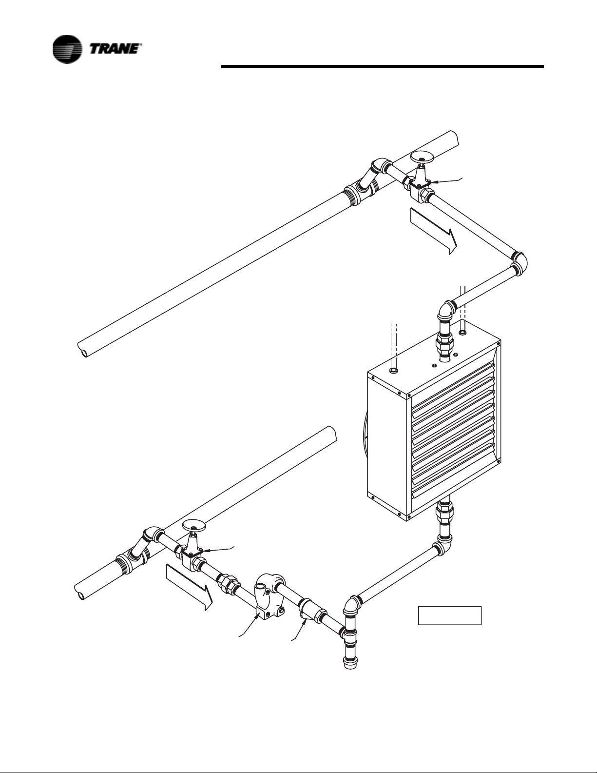
Piping
To provide proper coil operation,
follow all piping recommendations
listed in this manual.
See Figure 13 through Figure 17 for
proper pipe connections.
Follow standard practices and codes
when installing the piping. Provide
swing joints for expansion purposes,
unions and shut-off valves for
servicing purposes and as illustrated
in Figure 13 through Figure 17,
valves and traps for control
purposes. Use 45 degree angle runoffs from all supply and return mains.
Dirt pockets should be the same pipe
size as the return tapping of the unit
heater. Also, pipe size in the
branchoff should be the same size as
the tapping in the traps. Beyond the
trap, the return lateral pipe should be
increased one size up to the return
main.
It is assumed that the design
engineer has selected the type of
system to be used. The sketches
shown are for different types of
steam systems or hot water systems.
For sizing of piping, traps, filter, etc.,
consult ASHRAE guides of the
manufacturer’s literature on these
products.
It is important that the system be
kept clean. Care should be exercised
that excessive joint materials or
foreign substances be kept out of the
system.
On steam systems it is
recommended that the unit be
installed level for proper condensate
drainage. Swing joints should be
used in piping, and pipes should be
pitched down from units so that
condensate can drain freely.
20 UH-SVX01A-EN
Page 21

OSHA Fan Guard/Louver
Cone Diffuser Installation
Detail
WARNING
Hazardous Voltage
Do not mount either the Louver
Cone Diffuser or OSHA Fan Guard
while unit is in operation or severe
personal injury may occur.
Disconnect all power supplies to the
unit before installing the Louver
Cone Diffuser or OSHA Fan Guard.
The figures below show how both
the OSHA Fan Guard and the Louver
Cone Diffuser are installed on the
Vertical Steam and Hot Water Unit
Heater. Figure 20 and Figure 21
detail how the louver cone diffuser
and OSHA guard are attached to the
unit. Figure 22 and Figure 23 show
full views of the vertical steam and
hot water unit with a Louver Cone
Diffuser and OSHA Fan Guard
attached.
To meet CSA and OSHA
requirements, units mounted below
8 feet (2.4 meters) must be equipped
with an OSHA Fan Guard.
The same screws and washers are
provided with both the OSHA fan
guard and Louver Cone Diffuser. The
screws and washers are used in
conjunction with the Nutserts to
support the wire guard or diffuser to
the orifice panel (bottom of vertical
unit).
Fan Guard/Louver Installation
Figure 20. Louver Cone Diffuser
\
Figure 21. OSHA Fan Guard
UH-SVX01A-EN 21
Page 22
Fan Guard/Louver Installation
Figure 22. Vertical Unit with Louver Cone Diffuser
Figure 23. Vertical Unit with OSHA Fan Guard
22 UH-SVX01A-EN
Page 23
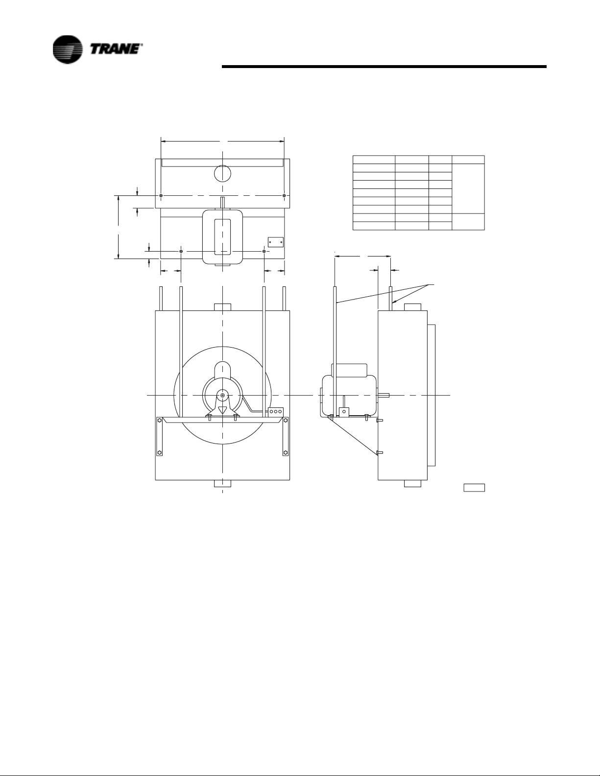
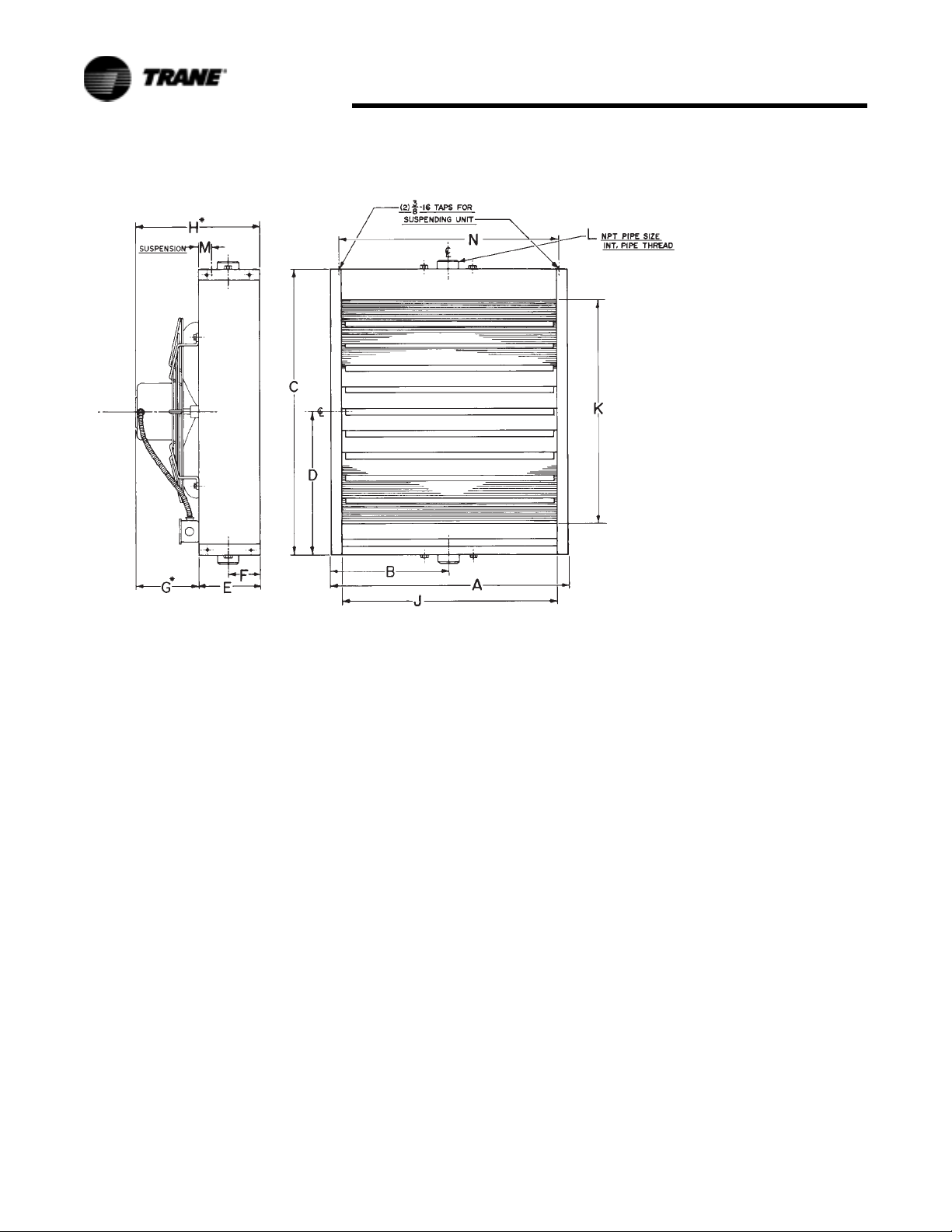
Dimensional Data: P Model
Dimensional Data
H
K
F
B
STEAM
RETURN
OR
HOT WATER
SUPPLY
T
P
Figure 24. Models 42-80
GR
A
(4) MOUNTING HOLES
THREAD TAPS
CEILING
D
H
K
R
3
/8 - 16 FOR 42P-80P
P
T
C
E
V
G A
R
L
S
STEAM
SUPPLY
OR
HOT WATER
RETURN
Table 8. Roughing in Dimensional Data - Model Size 42-80
Unit Capacity (MBH) Fan Dia. A B C D E F G H K L (Min.) P (NPT) R S T U V
042 11 1/4 18 1/4 4 5/8 1 1/4 11 3/4 3/4 4 11 1 3/8 1 7/8 7 1 1/2 3 5/8 6 5/8 2 3/4 11 3 5/8
064 13 1/2 21 1/4 4 5/8 1 5/8 14 1 4 14 1 3/8 1 7/8 7 1 1/2 3 5/8 7 1/8 2 3/4 14 3 5/8
080 13 1/2 21 1/4 6 1/8 1 5/8 14 1 3 14 1 3/8 1 7/8 7 1 1/2 3 5/8 8 5/8 2 3/4 14 3 5/8
UH-SVX01A-EN 23
Page 24
Dimensional Data
K
H
H
V
UA
V
K
GR
A
(4) MOUNTING HOLES 3/8 - 16 FOR 102P-384P
THREAD TAPS
CEILING
F
B
S
C
E
D
R
1
/2 - 13 FOR 500P-720P
P
T
T
P
L
STEAM
SUPPLY
OR
HOT WATER
RETURN
STEAM
RETURN
OR
HOT WATER
SUPPLY
Figure 25. Models 102-720
Table 9. Roughing in Dimensional Data - Model Size 102-720
Unit
Capacity
(MBH)
102 16 3/4 25 1/4 6 1/8 2 17 1/2 1 1/8 3 17 1 3/8 2 3/4 7 1 1/2 4 1/8 9 1/8 2 3/4 17 4 1/8
122 16 3/4 25 1/4 6 1/8 2 17 1/2 1 3/4 3 17 1 3/8 2 3/4 7 1 1/2 4 1/8 9 3/4 2 3/4 17 4 1/8
146 19 3/4 29 1/2 6 1/8 2 3/8 20 5/8 1 1/4 4 20 1/2 1 3/4 3 1/2 7 2 4 1/2 9 5/8 2 3/4 20 1/2 4 1/2
166 19 3/4 29 1/2 6 1/8 2 3/8 20 5/8 1 3/4 4 20 1/2 1 3/4 3 1/2 7 2 4 1/2 10 1/8 2 3/4 20 1/2 4 1/2
202 19 3/4 29 1/2 7 5/8 2 3/8 20 5/8 2 4 20 1/2 1 3/4 3 1/2 7 2 4 1/2 12 2 3/4 20 1/2 4 1/2
252 25 1/4 37 1/2 7 5/8 3 26 3/8 1 3 1/2 28 1 3/4 3 1/2 7 2 4 3/4 11 5/8 2 3/4 18 9 3/4
280 25 1/4 37 1/2 7 5/8 3 26 3/8 1 1/4 3 1/2 28 1 3/4 3 1/2 7 2 4 3/4 11 3/4 2 3/4 18 9 3/4
336 25 1/4 37 1/2 7 5/8 3 26 3/8 2 1/8 4 28 1 3/4 3 1/2 7 2 4 3/4 12 3/4 2 3/4 18 9 3/4
384 25 1/4 37 1/2 9 1/8 3 26 3/8 2 3 1/2 28 1 3/4 3 1/2 7 2 4 3/4 14 1/8 2 3/4 18 9 3/4
500 30 1/2 42 9 1/8 3 1/2 31 1/4 1 5/8 3 30 2 1/4 4 1/4 7 2 1/2 6 14 1/4 3 30 6
600 30 1/2 42 12 1/8 3 1/2 31 1/4 2 1/8 3 30 2 1/4 4 1/4 7 2 1/2 6 17 3/4 3 30 6
720 30 1/2 42 13 5/8 3 1/2 31 1/4 3 4 30 2 1/4 4 1/4 7 2 1/2 6 20 1/4 3 30 6
Fan
Dia. A B C D E F G H KL (Min.)P (NPT) R S T U V
24 UH-SVX01A-EN
Page 25
Dimensional Data: S Model
Dimensional Data
Figure 26. Serpentine Type Models A08, A18, A25, A36
Note: Motors are totally enclosed, thermally protected, sleeve bearing, with 4" (w) x 2" (h) conduit connection boxes.
3/8-16 nutserts are attached to enclosure for balanced hanging.
Table 10. Table 3- Serpentine Models
MODEL
A08 16 (406) 18 (457) 16 7/32 (412) 11 1/4 (286) 4 1/4 (108) 5 9 (229) 22 (10.0)
A18 16 (406) 18 (457) 16 7/32 (412) 11 1/4 (286) 4 1/4 (108) 5 10 (254) 24 (10.9)
A25 16 (406) 18 (457) 16 7/32 (412) 11 1/4 (286) 4 1/4 (108) 5 10 (254) 25 (11.3)
A36 18 1/2 (470) 20 1/2 (521) 18 22/32 (475) 13 3/4 (349) 5 1/8 (130) 6 12 (305) 31 (14.0)
H inches
(mm)
W inches
(mm)
A inches
(mm)
B inches
(mm)
C inches
(mm)
NO. OF
LOUVERS
NOM. FAN
DIAM. inches
(mm)
APPROX.
SHIP WT. lbs.
(kg)
UH-SVX01A-EN 25
Page 26
Dimensional Data
Figure 27. Header Type Models 18 thru 360
Note: Motors are totally enclosed, thermally protected, sleeve bearing, with 4" (w) x 2" (h) conduit connection boxes.
3/8-16 nutserts are attached to enclosure for balanced hanging.
26 UH-SVX01A-EN
Page 27

Table 11. Header Models
MODEL
inches
(mm)
18 14 5/8
(371)
243614 5/8
(371)
486017 1/8
(435)
72 18 3/8
(467)
84 20 7/8
(530)
96
19 5/8
108
(498)
120 20 7/8
(530)
132
23 3/8
144
(594)
156 23 3/8
(594)
180
24 5/8
204
(625)
240 27 7/8
(708)
280 27 7/8
(708)
300
33 3/8
360
(848)
A
B
inches
(mm)
7 5/16
(186)
7 5/16
(186)18(457)9(229)
8 9/16
(217)
9 3/16
(233)
10 7/16
(265)
9 13/16
(249)24(610)12(305)
10 7/16
(265)
11 11/16
(297)
11 11/16
(297)
12 5/16
(313)29(737)
13 15/16
(354)
13 15/16
(354)
16 11/16
(424)
C
inches
(mm)
15
(381)
20 1/2
(521)
21 3/4
(552)
24 1/4
(616)
25 1/4
(641)
27 3/4
(705)
27 3/4
(705)
30 1/4
(768)
30 1/4
(768)
37 3/4
(959)
D
inches
inches
(mm)
(mm)
7 1/2
6 1/8
(191)
(156)
6 1/8
(156)
10 1/4
10 7/8
12 1/8
12 5/8
13 7/8
13 7/8
14 1/2
15 1/8
15 1/8
18 7/8
5 7/8
(260)
(149)
(276)6(152)
6 1/8
(308)
(156)
6 5/16
(160)
6 5/16
(321)
(160)
6 5/16
(352)
(160)
6 5/16
(352)
(160)
6 3/8
(368)
(162)
8 1/8
(384)
(206)
8 1/8
(384)
(206)
(479)9(229)
Dimensional Data
E
F
inches
(mm)
2 15/16
(75)
2 15/16
(75)
2 15/16
(75)
2 15/16
(75)
2 15/16
(75)
3 3/16
(81)
3 3/16
(81)
3 3/16
(81)
3 3/16
(81)
3 3/16
(81)
3 3/16
(81)
3 3/16
(81)
3 3/16
(81)
G*
inches
(mm)
3 1/4
(83)
3 1/4
(83)
5 1/16
(129)
5 1/16
(129)
5 11/16
(144)
7 1/2
(191)
6 11/16
(170)13(330)
7 5/8
(194)14(356)21(533)
7 7/16
(189)
7 7/16
(189)
5 7/8
(149)14(356)
9-5/8
(244)
9 5/8
(244)
H*
inches
(mm)
9 3/8
(238)
9 3/8
(238)
10 15/16
(278)
11 1/16
(281)16(406)
11 13/16
(300)
13 13/16
(351)
13 3/4
(349)
13 3/4
(349)
17 3/4
(451)
18 5/8
(473)31(787)
J
inches
inches
(mm)
(mm)
12 1/4
12 1/4
14 3/4
18 1/2
17 1/4
18 1/2
22 1/4
25 1/2
25 1/2
9 1/2
(311)
(241)
12 1/2
(311)
(318)
(375)15(381)
16 1/4
(413)
18 3/4
(470)
(476)
17 1/2
(438)
(445)
18 3/4
(470)
(476)
21 1/4
(540)
21
21 1/4
(533)
(540)
22 1/2
(565)
(572)
23 3/4
(648)
(603)2(51)
23 3/4
(648)
(603)2(51)
31 1/4
(794)2(51)
K
L
inches
(mm)
1 1/4
(32)
1 1/4
(32)
1 1/4
(32)
1 1/4
(32)
1 1/4
(32)
1 1/2
(38)
1 1/2
(38)
1 1/2
(38)
1 1/2
(38)
1 1/2
(38)
M
inches
(mm)
2 1/4
(57)
2 1/4
(57)
1 3/4
(44)
1 3/4
(44)
1 3/4
(44)
1 3/4
(44)
1 3/4
(44)
1 3/4
(44)
1 3/4
(44)
1 3/4
(44)
1 3/4
(44)
1 3/4
(44)
1 3/4
(44)
N
inches
(mm)
12 7/8
(327)
12 7/8
(327)
15 3/8
(391)
16 5/8
(422)
19 1/8
(486)
17 7/8
(454)
19 1/8
(486)
21 5/8
(549)
21 5/8
(549)
22 7/8
(581)
26 1/8
(664)
26 1/8
(664)
31 5/8
(803)
NOM.
NO.
FAN
OF
DIAM.
LOU-
inches
VERS
(mm)
49
(229)26(11.8)
510
(254)30(13.6)
612
(305)41(18.6)
714
(356)44(19.9)
814
(356)47(21.3)
816
(406)49(22.2)
818
(457)59(26.7)
918
(457)74(33.5)
918
(457)74(33.5)
918
(457)90(40.8)
10 20
(508)
10 20
(508)
13 24
(610)
APPROX.
SHIP
WT. lbs.
(kg)
125
(57)
118
(53)
154
(69.8)
* Applies to standard motor with standard fan guard. When optional motors or OSHA fan guards are requested, dimensions will change according to the
substitutions made.
NOTES
1. Standard motor and standard guard shown.
2. Optional OSHA guards available for all units with 1 phase motors.
3. All 3 phase and explosion proof motors are shelf mounted.
UH-SVX01A-EN 27
Page 28
Technical Data: S Models
The performance data listed in
Tab l e 11 includes sound ratings. The
ratings provide a guide in
determining the acceptable degree
of loudness in particular occupancy
situations.
Certain general rules apply to
specific selection of unit heaters with
regard to degree of quietness (or
loudness);
• The greater the fan diameter, the
higher the sound level.
• The higher the motor RPM, the
higher the sound level. Note that
on most units the lower the
speed mode results in lowering
the sound rating one increment.
• Selecting a larger number of
smaller units generally results in
lower overall noise levels than
fewer large units.
All horizontal steam and hot water
unit heater motors, whether fan
guard or shelf-mounted, are isolated
from the mechanical mount by
resilient isolators. This mounting
along with balanced fan blades and
excellent overall construction
integrity, assures you the utmost in
quiet operation.
The following table outlines SOUND
RATING for various applications. The
lower the number, the quieter the
unit and the lower the sound
requirement.
Te c h n i c a l D a t a
CATEGORY OF AREA SOUND RATING
apartment, assembly hall, classrooms, churches, courtrooms, executive
offices, hospitals, libraries, museums, theatres
dining rooms, general offices, recreation areas, small retail stores II
restaurants, banks, cafeterias, department stores, public buildings,
service stations
gymnasiums, health clubs, laundromats, supermarkets IV
garages, small machine shops, light manufacturing V
Factories, foundries, steel mills III-VII*
*Depending on specific use in these facilities,
size of operation, etc.
Table 12. Corrections When Using Glycol Solution in System
Propylene
Glycol
Heat transfer @ 180°F (82°C) with
no increase inflow rate
G.P.M. Req'd. @ 180°F (82°C), 20°F
(11°C) ∆
curve)
Pump Head Req'd. @ 180°F (82°C)
w/increase in G.P.M.
Specify gravity (water = 1.0) 1.045-1.055*
Pounds/Gallons @ 60°F (16°C)
(water = 8.3453 Pound/Gallon)
pH @ 50% by volume 9.5
Freezing Point by volume
t (no correction to pump
*Compared to water.
20% solution .97*
50% solution .90*
1.10%*
1.23%*
8.77
55% -
50% -28°F (-33°C)
40% -13°F (-25°C)
30% + 4°F (-16°C)
20% +17°F (- 8°C)
I
III
Table 13. Approximate factors at varying altitudes
Altitude Factor
Sea level - 1000 ft. (305m) 1.00
1000 ft. - 3000 ft. (915m) .958
3000 ft. - 5000 ft. (1524m) .929
5000 ft. - 7000 ft. (2134m) .900
7000 ft. - 10000 ft. (3048m) .871
28 UH-SVX01A-EN
Page 29
Technical Data
Technical Data: P Model
The performance data listed in
Ta b l e 1 3, Ta b l e 1 4 , and Ta b l e 1 5
include sound ratings. The ratings
provide a guide in determining the
acceptable degree of loudness in
particular occupancy situations.
Certain general rules apply to specific
selection of unit heaters with regard
to degree of quietness (or loudness);
• The greater the fan diameter, the
higher the sound level.
• The higher the motor RPM, the
higher the sound level. Note that
on most units the lower the
speed mode results in lowering
the sound rating one increment.
• Selecting a larger number of
smaller units generally results in
lower overall noise levels than
fewer large units.
All vertical steam and hot water unit
heater motors, whether fan guard or
shelf-mounted, are isolated from the
mechanical mount by resilient
isolators. This mounting along with
balanced fan blades and excellent
overall construction integrity, assures
you the utmost in quiet operation.
The following table outlines sound
ratings for various applications. The
lower the number, the quieter the
unit and the lower the sound
requirement.
Category of Area Sound Rating
apartment, assembly hall, classrooms, churches, courtrooms, executive
offices, hospitals, libraries, museums, theatres
dining rooms, general offices, recreation areas, small retail stores II
restaurants, banks, cafeterias, department stores, public buildings,
service stations
gymnasiums, health clubs, laundromats, supermarkets IV
garages, small machine shops, light manufacturing V
factories, foundries, steel mills III-VII*
* Depending on specific use in these facilities,
size of operation, etc.
I
III
Table 14. Corrections When Using Glycol Solution in System
Propylene
Glycol
Heat transfer @ 180°F with no
increase inflow rate
G.P.M. Req'd. @ 180°F, 20°F ∆ t (no
correction to pump curve)
Pump Head Req'd. @ 180°F w/
increase in G.P.M.
Specify gravity (water = 1.0) 1.045-1.055*
Pounds/Gallons @ 60°F (water =
8.3453 Pound/Gallon)
pH @ 50% by volume 9.5
Freezing Point by volume
*Compared to water.
20% solution .97*
50% solution .90*
1.10%*
1.23%*
8.77
55% -
50% -28°F
40% -13°F
30% + 4°F
20% +17°F
Table 15. Approximate factors at varying altitudes
Altitude Factor
Sea level - 1000 ft. 1.00
1000 ft. - 3000 ft. .958
3000 ft. - 5000 ft. .929
5000 ft. - 7000 ft. .900
7000 ft. - 10000 ft. .871
UH-SVX01A-EN 29
Page 30
Options
Options: S Models
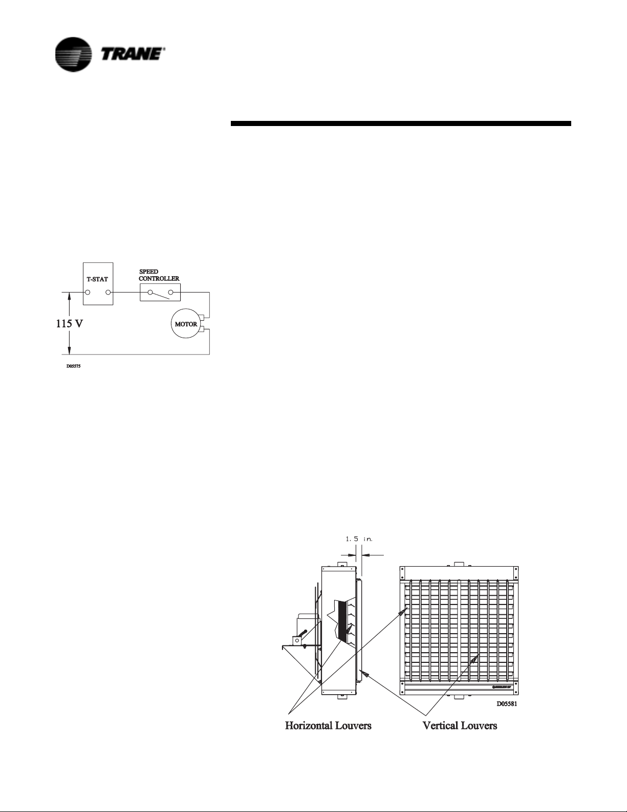
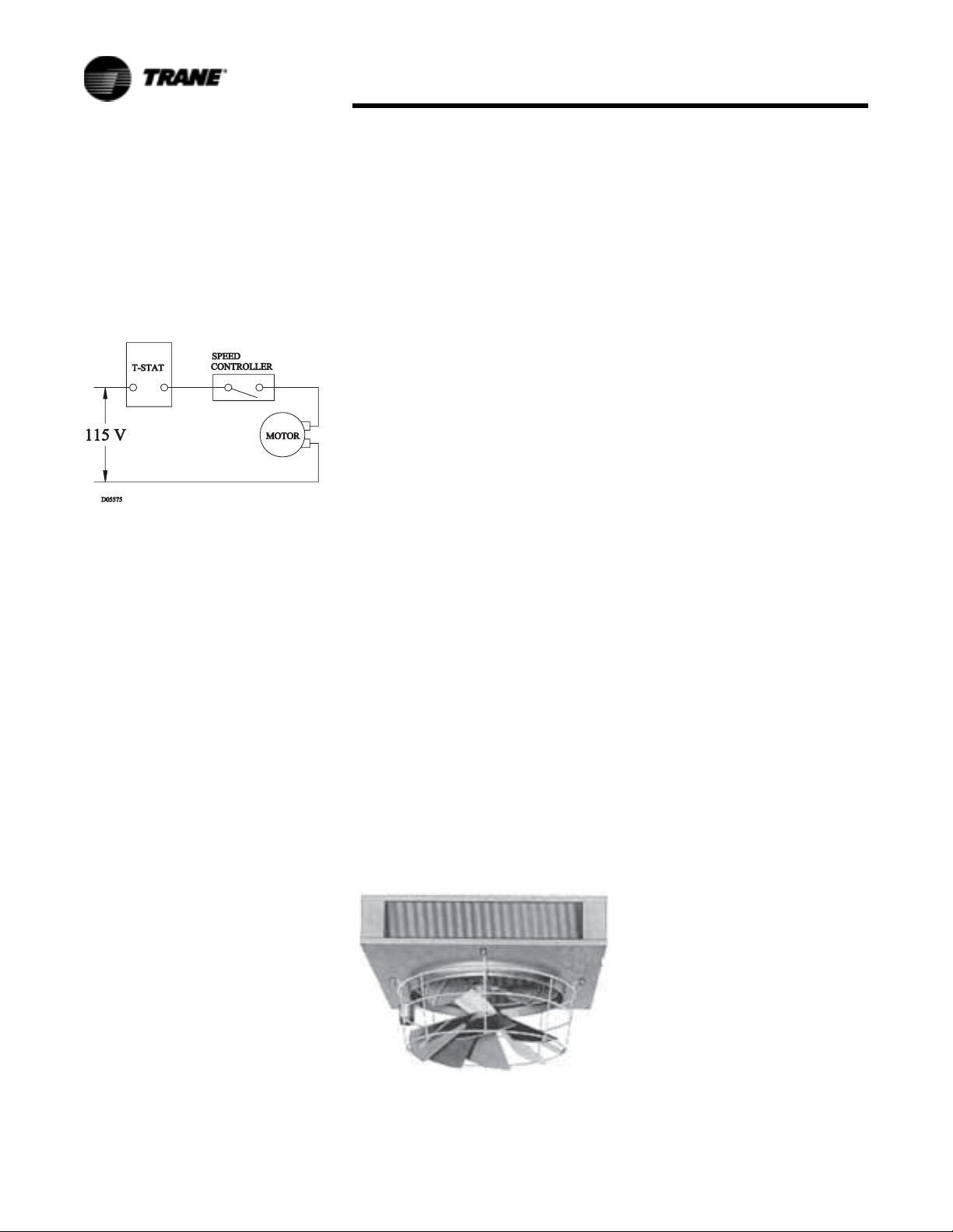
Variable Speed Control 115 Volt
Only (optional)
The solid state speed controller may
be installed at any convenient
location and is suitable for surface or
flush type mounting. A Standard
electrical single or double gang wall
box is recommended as in Figure 28.
Figure 28. Wiring Diagram of
Speed Control Installation
Installation Procedure:
1. Attach the control's leads to the
electrical leads in the control box
using wire nuts. The speed
control is to be wired in series
with the motor. See wiring
diagram in
2. Make certain wire nuts are tight
with no copper wire being
exposed.
3. Place wires and wire nuts back
into box allowing room for the
control to fit in box also.
4. Mount speed control to box
using number 6 flathead screws
provided.
Setting the Control:
1. Tu r n t h e c o n t rol shaft fully
clockwise. If the motor is not
running at the desired low
speed, adjust the trim on the
face of the control for low speed
setting using a small
screwdriver.
2. Rotate the control shaft counter
clockwise. The speed will
increase smoothly from
minimum to maximum and then
switch off.
Figure 28.
3. Mount face plate with screw
provided and attach control
knob.
Strap-On Water Control
A SPDT strap-on type hot water
control with 100° to 240°F (38 to
116°C) rated at 10 amps at 120V is
also available. Control can be used
for direct or reverse acting
applications as high or low limit.
Steam Pressure Control
SPDT switch opens on a rise in
pressure. Control is automatically
reset, has a range of 0 to 15 PSIG (0
to 103 kPa) and has an adjustable
differential. Other actions, ranges,
circuits and manual reset
models are available on request.
Horizontal and Vertical Louvers
Horizontal louvers are standard on
all models. Vertical louvers are an
optional accessory on all models.
Vertical louvers are installed on built
to order units or shipped loose for
field installation.
Thermostats
Line voltage wall thermostats are in
stock for immediate shipment. All
models are SPST with bimetal
thermometer, knob-type set point
adjustment, 40 to 90°F (5 to 30°C)
range and selector switches.
Standard duty models with "offauto" and "auto-off-fan" and a heavy
duty model with "auto-off-fan"
switching are available. Other
models available on request. Plastic
tamperproof one size fits all
thermostat guards are also available.
Manual Starters
Single and three-phase models are
available. Standard models are
single-speed, toggle-operated,
NEMA Type 1 and are surfacemounted.
Wall Mounted Speed Controllers
Units with standard motors up to
Model 108 (115/1/60) can be operated
at reduced speeds by addition of
optional speed controller. Controller
is 5 amps, pre-set at factory for
maximum and minimum speeds,
with intermediate speeds infinitely
controllable. All 1/3, 1/2 HP and 230V
motors operate only at rated speed
and CFM - See Tables.
CAUTION
When using electrical accessories,
always refer to the accessory
manufacturer's installation manual
for proper use, location and wiring
instructions.
Figure 29. Horizontal and Vertical Louver Mounting
30 UH-SVX01A-EN
Page 31
Options
Options: P Models
Variable Speed Control 115 Volt
Only (optional)
The solid state speed controller may
be installed at any convenient
location and is suitable for surface or
flush type mounting. A standard
electrical single or double gang wall
box is recommended as in Figure 30.
Figure 30. Wiring Diagram of
Speed Control Installation
Installation Procedure:
1. Attach the control's leads to the
electrical leads in the control box
using wire nuts. The speed
control is to be wired in series
with the motor. See wiring
diagram in
2. Make certain wire nuts are tight
with no copper wire being
exposed.
3. Place wires and wire nuts back
into box allowing room for the
control to fit in box also.
4. Mount speed control to box
using number 6 flathead screws
provided.
Setting the Control:
1. Turn the control shaft fully
clockwise. If the motor is not
running at the desired low
speed, adjust the trim on the face
of the control for low speed
setting using a small
screwdriver.
2. Rotate the control shaft counter
clockwise. The speed will
increase smoothly from
minimum to maximum and then
switch off.
Vertical Louver Cone Diffuser
(optional)
Rubber mounts and mounting nuts
and bolts are provided with each
louver cone diffuser. Attach the
Figure 30.
diffuser to the bottom of the unit
heater as shown in Figure 51.
Mounting holes are provided in the
unit base plate.
Adjust the diffuser to provide the
desired air pattern.
Strap-On Water Control
A SPDT strap-on type hot water
control with 100° to 240°F (38 to
116°C) rated at 10 amps at 120V is
also available. Control can be used
for direct or reverse acting
applications as high or low limit.
Steam Pressure Control
SPDT switch opens on a rise in
pressure. Control is automatically
reset, has a range of 0 to 15 PSIG (0
to 103 kPa) and has an adjustable
differential. Other actions, ranges,
circuits and manual reset models
are available on request.
Thermostats
Line voltage wall thermostats are in
stock for immediate shipment. All
models are SPST with bimetal
thermometer, knob-type set point
adjustment, 40 to 90°F (5 to 30°C)
range and selector switches.
Standard duty models with "off-auto"
and a heavy duty model with "autoofffan" switching are available. Other
models available on request. Plastic
tamperproof one size fits all
thermostat guards are also available.
Wall Mounted Speed Controllers
Motors up to and including 1/8 HP
(115V) can be operated at reduced
speeds by addition of optional speed
controller. Controller is 5 amps, preset at factory for maximum and
minimum speeds, with intermediate
Figure 31. Louver Cone Diffuser
Attached to Vertical Unit Heater
speeds indefinitely controllable. All 1/
3, 1/2 HP and 230V motors operate
only at rated speed and CFM - See
Charts.
Manual Starters
Single and three-phase models are
available. Standard models are
single-speed, toggle-operated,
NEMA Type 1 and are surfacemounted.
CAUTION:
When using electrical accessories,
always refer to the accessory
manufacturer's installation manual
for proper use, location and wiring
instructions.
UH-SVX01A-EN 31
Page 32

Electrical Connections
Electrical Connections: P
Model
WARNING
Hazardous Voltage
Disconnect all electric power
including remote disconnects before
servicing. Failure to disconnect
power before servicing can cause
severe personal injury or death.
WARNING
Hazardous Voltage
Do not use any tools (i.e.
screwdriver, pliers, etc.) across the
terminals to check for power. Use a
voltmeter. Failure to disconnect
power before servicing can cause
severe personal injury or death.
Standard units are shipped for use
on 115 volt, 60 hertz single phase
electric power. The motor nameplate
and electrical rating on the
transformer should be checked
before energizing the unit heater
electrical system. All external wiring
must conform to ANSI/NFPA No. 702002, National Electrical Code (or the
latest edition) and applicable current
local codes; in Canada, to the
Canadian Electrical Code, Part 1 CSA
Standard C22.1.
It is recommended that the electrical
power supply to each unit heater be
provided by a separate, fused and
permanently live electrical circuit. A
disconnect switch of suitable
electrical rating for each unit heater
should be located as close to the
controls as possible. Each unit heater
must be electrically grounded in
accordance with National Electric
Code, ANSI/NFPA No. 70-2002 (or
the latest edition of) or CSA
Standard C22.1. Sample wiring
connections are depicted in
Figure 38 through Figure 40.
Operation
Most basic unit heater systems are
controlled by a room thermostat.
Locate thermostat on inner wall or
column so that optimum control
could be obtained for that area. Set
thermostat for desired temperature.
On steam systems a low limit may
be used to prevent fan from blowing
cold air unless the heater has steam
passing through the coil.
Small hot water systems could have
the circulating pump controlled
directly by the room thermostat. On
large systems, zone valves could be
used to control the individual unit
heater where constant water
circulation is used on the main
system.
A louvered cone air diffuser is
readily available as an optional
accessory for vertical unit heaters.
See catalog for details.
Thermostat Wiring and Location
Note: The thermostat must be
mounted on a vertical
vibration-free surface free
from air currents and in
accordance with the
furnished instructions.
Mount the thermostat approximately
5 feet (1.5 m) above the floor in an
area where it will be exposed to a
free circulation of average
temperature air. Always refer to the
thermostat instructions as well as
our unit wiring diagram and wire
accordingly. Avoid mounting the
thermostat in the following
locations:
1. Cold areas - Outside walls or
areas where drafts may affect
the operation of the control.
2. Hot areas - Areas where the
sun’s rays, radiation, or warm air
currents may affect control
operation.
3. Dead areas - Areas where air
cannot circulate freely, such as
behind doors or in corners.
Note: For all wiring connections,
refer to the wiring diagram
on the motor nameplate.
Should any original wire
supplied with the heater
have to be replaced, it must
be replaced with wiring
material having a
temperature rating of at least
105° C .
Motors
The standard 115/1/60 motors
provided on Vertical Unit Heaters are
totally enclosed, Class “B” insulated
and have built-in thermal overload
protection.
Vertical Units 42 through 80 use
sleeve type bearings. Vertical Units
122 through 280 use permanent split
capacitor motors with ball bearings.
All sleeve bearing motors have oil
holes to allow lubrication. Ball
bearing motors are permanently
lubricated although some three
phase or special motors have
removable plugs which will allow
field installation of grease fittings.
The standard 42 through 102 motors
can be converted to variable speed
operation with the addition of the
solid state speed control.
See Figure 32 through Figure 37 for
typical wiring diagrams.
32 UH-SVX01A-EN
Page 33
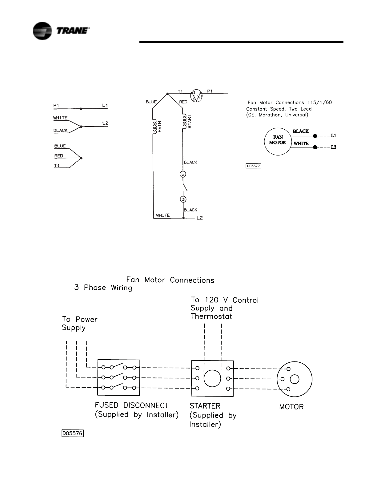
Figure 32. Fan Motor Connections
Low Voltage with Protector Select
Rotation (CCW shown)(Marathon)
For CW Rotation Interchange (Red
and black lead)
Electrical Connections
Figure 35. Fan Motor Connections
115/1/60 Constant Speed, Two Lead
(GE, Marathon, Universal)
Figure 34. Fan Motor Connections
Low Voltage CCW Internal
(Marathon)
Figure 33.
UH-SVX01A-EN 33
Page 34

Electrical Connections
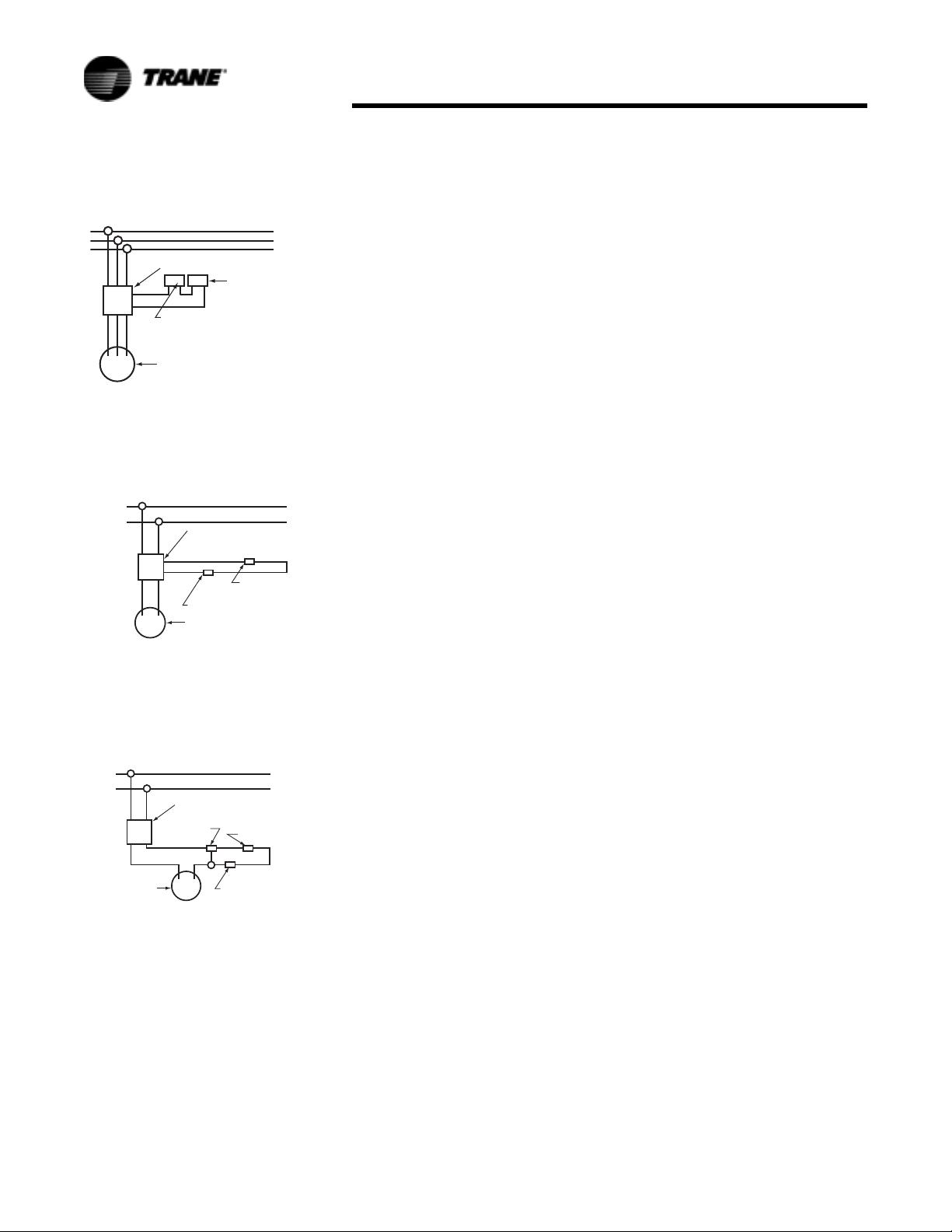
Wiring Installation: P Model
Notice
1. When using a speed controller,
always locate the thermostat
between the speed controller
and the line, not between the
motor and the controller.
2. For internal wiring and overload
protection on all starters, consult
the control manufacturer for
details.
3. When using thermostatic control
with a manual starter, be sure
that the electrical rating of the
thermostat is sufficient to carry
the motor current.
1 PHASE LINE
MANUAL STARTING
SWITCH
MOTOR
1 PHASE LINE
MAGNETIC
STARTING SWITCH
THERMOSTAT
MOTOR
THERMOSTATIC CONTROL
USING MAGNETIC STARTER
OPERATING SEVERAL UNITS
Figure 38.
1 PHASE LINE
MANUAL STARTING
SWITCH
THERMOSTAT
MOTOR
3 PHASE LINE
MANUAL STARTING
SWITCH
MOTOR
MANUAL CONTROL WITH
THREE PHASE MOTOR
Figure 41.
3 PHASE LINE
MAGNETIC
STARTING SWITCH
THERMOSTAT
MOTORS
MANUAL CONTROL WITH
SINGLE PHASE MOTOR
Figure 36.
1 PHASE LINE
MANUAL STARTING
SWITCH
MOTOR
ROOM THERMOSTAT
THERMOSTATIC CONTROL
WITH MANUAL STARTER
Figure 37.
SPEED CONTROLLER
SPEED CONTROLLER WITH
MANUAL STARTING SWITCH
Figure 39.
1 PHASE LINE
MAGNETIC
STARTING SWITCH
THERMOSTAT
SPEED CONTROLLERS WITH
MAGNETIC STARTING SWITCH
FOR OPERATING SEVERAL UNITS
MOTORS
SPEED
CONTROLLERS
Figure 40.
MOTOR
THERMOSTATIC CONTROL
OF SEVERAL THREE PHASE UNITS
Figure 42.
1 PHASE LINE
MANUAL STARTING
SWITCH
MOTOR
LIMIT CONTROLLER
ROOM THERMOSTAT
THERMOSTATIC CONTROL WITH
ACTING LIMIT CONTROLLER
AND MANUAL STARTER
REVERSE ACTING
Figure 43.
34 UH-SVX01A-EN
Page 35
Electrical Connections
3 PHASE LINE
MANUAL STARTING
SWITCH
LIMIT CONTROLLER
REVERSE ACTING
MOTOR
MANUAL CONTROL WITH
THREE PHASE MOTOR
THERMOSTAT
Figure 44.
1 PHASE LINE
MANUAL STARTER
WITH BUILT IN
SELECTOR SWITCH
THERMOSTAT
LIMIT CONTROLLER
MOTOR
THREE POSITION SELECTOR SWITCH
BUILT INTO MAGNETIC STARTER FOR
MANUAL OR THERMOSTATIC CONTROL
Figure 45.
1 PHASE LINE
MANUAL STARTING
SWITCH
SELECTOR
SWITCH
MOTOR
THREE POSITION SELECTOR SWITCH
USED FOR EITHER MANUAL
OR THERMOSTATIC CONTROL
THERMOSTAT
LIMIT CONTROLLER
Figure 46.
Electrical Connections: S
Model
WARNING
Hazardous Voltage
Disconnect all electric power
including remote disconnects before
servicing. Failure to disconnect
power before servicing can cause
severe personal injury or death.
WARNING
Hazardous Voltage
Do not use any tools (i.e. screwdriver,
pliers, etc.) across the terminals to
check for power. Use a voltmeter.
Failure to disconnect power before
servicing can cause severe personal
injury or death.
Standard units are shipped for use
on 115 volt, 60 hertz single phase
electric power. The motor nameplate
and electrical rating on the
transformer should be checked
before energizing the unit heater
electrical system. All external wiring
must conform to ANSI/NFPA No. 702002, National Electrical Code (or the
latest edition) and applicable current
local codes; in Canada, to the
Canadian Electrical Code, Part 1 CSA
Standard C22.1.
It is recommended that the electrical
power supply to each unit heater be
provided by a separate, fused and
permanently live electrical circuit. A
disconnect switch of suitable
electrical rating for each unit heater
should be located as close to the
controls as possible. Each unit heater
must be electrically grounded in
accordance with National Electric
Code, ANSI/NFPA No. 70-2002 (or the
latest edition) or CSA Standard C22.1.
Sample wiring connections are
depicted in Figure 49 through
Figure 57.
Operation
Most basic unit heater systems are
controlled by a room thermostat.
Locate thermostat on inner wall or
column so that optimum control can
be obtained for that area. Set
thermostat for desired temperature.
On steam systems a low limit may be
used to prevent fan from blowing
cold air unless the heater has steam
passing through the coil.
Small hot water systems could have
the circulating pump controlled
directly by the room thermostat. On
large systems, zone valves could be
used to control the individual unit
heater where constant water
circulation is used on the main
system.
Horizontal louvers are standard
equipment on horizontal unit
heaters, vertical louvers are available
as an optional accessory.
Thermostat Wiring and Location
Note: The thermostat must be
mounted on a vertical
vibration-free surface free
from air currents and in
accordance with the
furnished instructions.
Mount the thermostat approximately
5 feet (1.5 m) above the floor in an
area where it will be exposed to a
free circulation of average
temperature air. Always refer to the
thermostat instructions as well as our
unit wiring diagram and wire
accordingly. Avoid mounting the
thermostat in the following locations:
1. Cold areas - Outside walls or
areas where drafts may affect the
operation of the control.
2. Hot areas - Areas where the
sun's rays, radiation, or warm air
currents may affect control
operation.
3. Dead areas - Areas where air
cannot circulate freely, such as
behind doors or in corners.
Note: For all wiring connections,
refer to the wiring diagram
on the motor nameplate.
Should any original wire
supplied with the heater have
to be replaced, it must be
replaced with wiring material
having a temperature rating
of at least 105° C.
UH-SVX01A-EN 35
Page 36
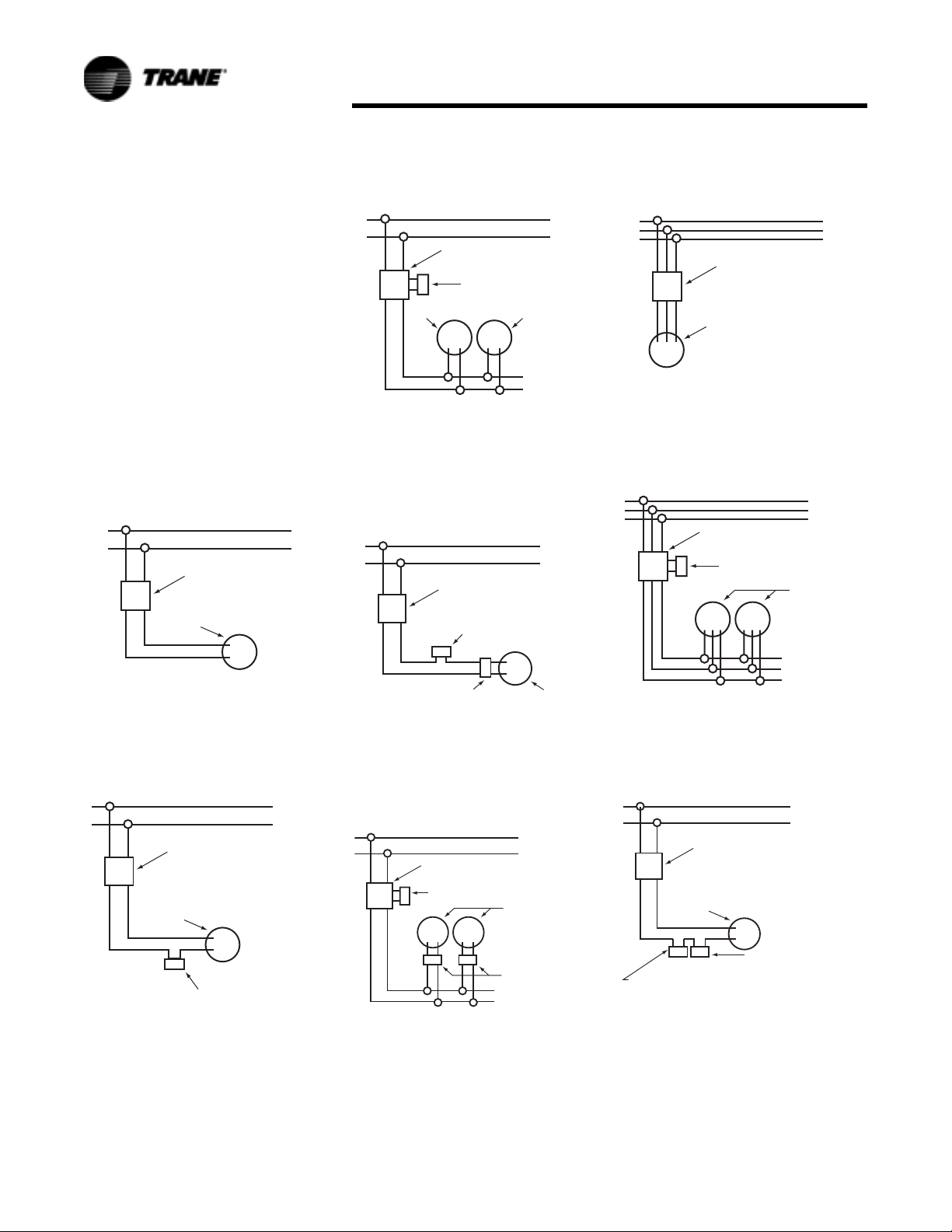
Electrical Connections
Wiring Installation: S Model
Notice
1. When using a speed controller,
always locate the thermostat
between the speed controller
and the line, not between the
motor and the controller.
2. For internal wiring and overload
protection on all starters, consult
the control manufacturer for
details.
3. When using thermostatic control
with a manual starter, be sure
that the electrical rating of the
thermostat is sufficient to carry
the motor current.
1 PHASE LINE
MANUAL STARTING
SWITCH
MOTOR
1 PHASE LINE
MAGNETIC
STARTING SWITCH
THERMOSTAT
MOTOR
THERMOSTATIC CONTROL
USING MAGNETIC STARTER
OPERATING SEVERAL UNITS
Figure 49.
1 PHASE LINE
MANUAL STARTING
SWITCH
THERMOSTAT
MOTOR
3 PHASE LINE
MANUAL STARTING
SWITCH
MOTOR
MANUAL CONTROL WITH
THREE PHASE MOTOR
Figure 52.
3 PHASE LINE
MAGNETIC
STARTING SWITCH
THERMOSTAT
MOTORS
MANUAL CONTROL WITH
SINGLE PHASE MOTOR
Figure 47.
1 PHASE LINE
MANUAL STARTING
SWITCH
MOTOR
ROOM THERMOSTAT
THERMOSTATIC CONTROL
WITH MANUAL STARTER
Figure 48.
SPEED CONTROLLER
SPEED CONTROLLER WITH
MANUAL STARTING SWITCH
Figure 50.
1 PHASE LINE
MAGNETIC
STARTING SWITCH
THERMOSTAT
SPEED CONTROLLERS WITH
MAGNETIC STARTING SWITCH
FOR OPERATING SEVERAL UNITS
MOTORS
SPEED
CONTROLLERS
Figure 51.
MOTOR
THERMOSTATIC CONTROL
OF SEVERAL THREE PHASE UNITS
Figure 53.
1 PHASE LINE
MANUAL STARTING
SWITCH
MOTOR
LIMIT CONTROLLER
ROOM THERMOSTAT
THERMOSTATIC CONTROL WITH
ACTING LIMIT CONTROLLER
AND MANUAL STARTER
REVERSE ACTING
Figure 54.
36 UH-SVX01A-EN
Page 37

3 PHASE LINE
MANUAL STARTING
SWITCH
LIMIT CONTROLLER
REVERSE ACTING
MOTOR
MANUAL CONTROL WITH
THREE PHASE MOTOR
Figure 55.
1 PHASE LINE
MANUAL STARTER
WITH BUILT IN
SELECTOR SWITCH
Electrical Connections
THERMOSTAT
THERMOSTAT
LIMIT CONTROLLER
MOTOR
THREE POSITION SELECTOR SWITCH
BUILT INTO MAGNETIC STARTER FOR
MANUAL OR THERMOSTATIC CONTROL
Figure 56.
1 PHASE LINE
MANUAL STARTING
SWITCH
SELECTOR
SWITCH
MOTOR
THREE POSITION SELECTOR SWITCH
USED FOR EITHER MANUAL
OR THERMOSTATIC CONTROL
THERMOSTAT
LIMIT CONTROLLER
Figure 57.
UH-SVX01A-EN 37
Page 38
Motor Data: P Models
Motor Data
CAUTION
Voltage Selections
Select appropriate AMP, MCA, and
MOP for the multiple voltage
motors. For example, the AMP, MCA,
and MOP for Model 40 with a 230
volt Totally Enclosed motor is 1.1,
1.4, and 2.5 respectively.
Note: All motors are constant
speed and operate at top
speed as indicated in motor
data. Models through 1/8 H.P.
can be run at reduced speed
with addition of optional
variable speed switch. This
switch is factory-calibrated
for low and high speed
ratings, with intermediate
speeds infinitely controllable.
Models 166 through 720
operate at constant speed as
indicated in motor data.
Note: Stated draw is Full Load
(FLA). AMP draw varies by
motor manufacturer ± .2
AMPS. Verify FLA on motor
data plate.
For Table 16
* Optional variable speed switch is available.
** These motors have automatic thermal over-
load protection or impedance protection.
*** These motors are 230/460 volts only.
† Models 336 through 720 are not available for
either Totally Enclosed or Explosion Proof
with Overload 115/1/60 motor types.
Table 16. Standard (Totally Enclosed) Motor Type [MT=1]
Unit Model No. AMP MCA MOP HP RPM
115/1/60† Operating Voltage
42 1.23** 1.6 2.8 1/40* 1550
64 2.1** 2.6 4.7 1/20* 1550
80
102 1.2** 1.5 2.7 1/8* 1070
122
146
166
202 3.6** 4.5 8.1 1/4 1100
252 3.6** 4.5 8.1 1/4 1100
280 5.4** 6.8 12.2 1/2 1100
208-230/460/3/60 Operating Voltage
42 0.98-1.1/0.55 1.2-1.4/0.7 2.2-2.5/1.2 1/6 1140
64 0.98-1.1/0.55 1.2-1.4/0.7 2.2-2.5/1.2 1/6 1140
80
102 0.98-1.1/0.55 1.2-1.4/0.7 2.2-2.5/1.2 1/6 1140
122
146
166
202 1.2-1.4/0.7 1.5-1.8/0.9 2.7-3.2/1.6 1/4 1140
252 1.2-1.4/0.7 1.5-1.8/0.9 2.7-3.2/1.6 1/4 1140
280 1.8-2.0/1.0 2.3-2.5/1.3 4.1-4.5/2.3 1/2 1140
336 3.1-3.2/1.6 3.9-4.0/2.0 7.0-7.2/3.6 3/4 1140
384
500 5.3-5.0/2.5 6.6-6.3/3.1 11.9-11.3/5.6 1-1/2 1160
600
720 9.9-9.8/4.9 12.4-12.3/6.1 22.3-22.1/11.0 3 1165
575/3/60 Operating Voltage
42
64
80
102
122
146
166
202
252
280 0.8 1.0 1.8 1/2 1140
336 1.3 1.6 2.9 3/4 1140
384
500 2.0 2.5 4.5 1-1/2 1160
600
720 3.8 4.7 8.4 3 1165
2.3** 2.9 5.2 1/6 1100
0.98-1.1/0.55 1.2-1.4/0.7 2.2-2.5/1.2 1/6 1140
0.6 0.8 1.4 1/3 1140
38 UH-SVX01A-EN
Page 39

Motor Data
Table 17. Explosion Proof with Thermal Overload Motor Type [MT=2]
Unit Model
No. AMP MCA MOP HP RPM
115/1/60† Operating Voltage
42 3.8 4.8 8.6 1/6 1140
64 3.8 4.8 8.6 1/6 1140
80
102 3.8 4.8 8.6 1/6 1140
122
146
166
202 4.4 5.5 9.9 1/4 1140
252 4.4 5.5 9.9 1/4 1140
280 7.8 9.8 17.6 1/2 1140
208-230/460/3/60 Operating Voltage
42 1.0-1.0/0.5 1.3-1.3/0.6 2.3-2.3/1.1 1/6 1140
64 1.0-1.0/0.5 1.3-1.3/0.6 2.3-2.3/1.1 1/6 1140
80
102 1.0-1.0/0.5 1.3-1.3/0.6 2.3-2.3/1.1 1/6 1140
122
146
166
202 1.1-1.1/0.55 1.4-1.4/0.7 2.5-2.5/1.2 1/4 1140
252 1.1-1.1/0.55 1.4-1.4/0.7 2.5-2.5/1.2 1/4 1140
280 1.9/0.95*** 2.4/1.2 4.3/2.1 1/2 1140
336 3.1-3.2/1.6 3.9-4.0/2.0 7.0-7.2/3.6 3/4 1145
384
500 5.0/2.5*** 6.5/3.3 11.7/5.9 1-1/2 1150
600
720 10.0/5.0*** 12.5/6.3 22.5/11.3 3 1150
3.8 4.8 8.6 1/6 1140
1.0-1.0/0.5 1.3-1.3/0.6 2.3-2.3/1.1 1/6 1140
in motor data. All 1/4 H.P.
motors are P.S.C.
Note: Motors under 1/3 H.P. are
totally enclosed, frame
mounted, 115/1/60 with
thermal overload protection
and permanently lubricated
sleeve bearings with optional
speed controller available. 1/3
H.P. (115/1/60) motors are
open frame constant speed
with thermal over-load
protection and ball bearings.
1/3 H.P. (230V) and 1/2 H.P.
(230V) motors are open
frame constant speed with
thermal overload protection
and ball bearings.
Note: 1/3 and 1/2 H.P. motors are
available as 230V single and 3
phase in open frame and
explosion-proof housings, all
available as options. 1/3 and
1/2 H.P. motors operate at
single speed only.
Note: Stated AMP draw is Full Load
Amp (FLA). AMP draw varies
by motor manufacturer ± 0.2
AMPS. Verify FLA per unit
motor data plate.
For Table 17
* Optional variable speed switch is available.
** These motors have automatic thermal over-
load protection or impedance protection.
*** These motors are 230/460 volts only.
† Models 336 through 720 are not available for
either Totally Enclosed or Explosion Proof
with Overload 115/1/60 motor types.
Motor Data: S Models
CAUTION
Voltage Selections
Select appropriate AMP, MCA, and
MOP for the multiple voltage motors.
For example, the AMP, MCA, and
MOP for Models 360 with a 460 volt
Totally Enclosed motor is 1.3, 1.6, and
2.9 respectively.
Also refer to Maintenance section for
additional motor data.
UH-SVX01A-EN 39
Note: All motors are constant
speed and operate at top
speed as indicated in motor
data. Models 18 through 108,
including A08, A18, A25 and
A36 can be run at reduced
speed with addition of
optional variable speed
switch. This switch is factorycalibrated for low and high
speed ratings, with
intermediate speeds infinitely
controllable. Models 120
through 360 operate at
constant speed as indicated
Page 40
Motor Data
Table 18. Totally Enclosed Motor Type
Unit Model No. AMP MCA MOP HP RPM
115/1/60
18, 24, A08, A18 0.8 1 1.8 16W* 1550
A36 1.4 1.8 3.2 1/20* 1000
36, A25 1.2 1.5 2.7 25W* 1550
48, 60, 72 1.4 1.8 3.2 1/20* 1000
84, 96, 108 2.2 2.8 5.0 1/12* 1000
120, 132, 144, 156, 180, 204, 240 4.5 5.6 10.1 1/3 1140
280, 300, 360 5.4 6.8 12.2 1/2 1100
230/1/60
18, 24, A08, A18 0.4 0.5 0.9 16W 1550
A36 1.4 1.8 3.2 1/20† 1000
36, A25 0.6 0.8 1.4 25W 1550
48, 60, 72 1.4 1.8 3.2 1/20† 1000
84, 96, 108 2.2 2.8 5.0 1/12† 1000
120, 132, 144, 156, 180, 204, 240 4.5 5.6 10.1 1/3† 1140
280, 300, 360 5.4 6.8 12.2 1/2† 1100
208-230/460/3/60
48, 60, 72, 84, 96, 108, 120, 132, 144, 156, 180, 204,
240, 280, 300, 360
2.6-2.6/1.3 3.3-3.3/1.6 5.9-5.9/2.9 1/2** 1140
*Optional variable speed switch is available.
**These motors are without thermal overload protection.
†230/1/60 unit has 115/1/60 motor supplied with field installed stepdown transformer.
Table 19. Explosion Proof with Thermal Overload Motor Type
Unit Model No. AMP MCA MOP HP RPM AMP MCA MOP HP RPM
115-230/1/60 230/460/3/60
48, 60, 72, 84, 96, 108, 120, 132 3.7 4.6 8.3 1/6† 1140 - - - - -
144, 156, 180, 204 5.4 6.8 12.2 1/4† 1140 2.2/1.1 2.8/1.4 5.0/2.5 1/3 1140
240, 280, 300 7.4-3.7 9.3-4.7 16.7-8.3 1/3*** 1140 2.2/1.1 2.8/1.4 5.0/2.5 1/3 1140
360 7.4-3.7 9.3-4.7 16.7-8.3 1/2*** 1140 2.2/1.1 2.8/1.4 5.0/2.5 1/3 1140
†230/1/60 unit has 115/1/60 motor supplied with field installed stepdown transformer.
40 UH-SVX01A-EN
Page 41

Table 20. Model S Header Type Only
Output
Unit Size
018
024
036
048
060
072
084
096
108,000
108
120 120,000
132 132,000
144 144,000
156 156,000
180 180,000
204 204,000
240 240,000
BTU/
HR*
(kW)
18,000
(5.3)
16,200
(4.7)
24,000
(7.0)
21,600
(6.3)
36,000
(10.5)
32,400
(9.5)
48,000
(14.1)
43,200
(12.7)
60,000
(17.6)
54,000
(15.8)
72,000
(21.1)
64,800
(19.0)
84,000
(24.6)
75,600
(22.2)
96,000
(28.1)
86,400
(25.3)
(31.6)
97,200
(28.5)
(35.2)
(38.7)
(42.2)
(45.7)
(52.7)
(59.8)
(70.3)
Cond.
lbs./hr.
(kg/hr)
18.0
(8.2)75(7.0)
16.2
(7.3)68(6.3)
24.5
(11.1)
22.0
(10.0)90(8.4)
37.0
(16.8)
33.0
(14.9)
49.0
(22.2)
44.0
(19.9)
61.0
(27.6)
55.0
(24.9)
73.0
(33.1)
66.0
(29.9)
85.0
(38.5)
76.0
(34.4)
97.0
(43.9)
88.0
(39.9)
110.0
(49.8)
98.0
(44.4)
122.0
(55.3)
134.0
(60.7)
146.0
(66.1)
160.0
(72.5)
190.0
(86.1)
208.0
(94.2)
244.0
(110.5)
E.D.R.
Sq. Ft.
(sq. m)
(9.3)
(13.9)
(12.5)
(18.6)
(16.7)
(23.2)
(20.9)
(27.9)
(25.1)
(32.5)
(29.3)
(37.2)
(33.4)
(41.8)
(37.6)
(46.5)
(51.1)
(55.7)
(60.4)
(71.5)
(79.0)
1000
(92.9)
100
150
135
200
180
250
225
300
270
350
315
400
360
450
405
500
550
600
650
770
850
Steam Performance Data
Final Air
Deg. °F
(Deg. °C)
102
(39)
105
(41)
109
(43)
112
(44)
119
(48)
120
(49)
119
(48) 1/20
123
(51)
121
(49) 1/20
131
(55)
120
(49) 1/20
123
(51)
115
(46) 1/12
123
(51)
123
(51) 1/12
132
(56)
115
(46) 1/12
120
(49)
118
(48)
121
(49)
120
(49)
115
(46)
135
(57)
124
(51)
123
(51)
Motor HP
(kW) RPM
16 Watts
16 Watts
25 Watts
(.037)
(.037)
(.037)
(.062)
(.062)
(.062)
1/3
(.249)
1/3
(.249)
1/3
(.249)
1/3
(.249)
1/3
(.249)
1/3
(.249)
1/3
(.249)
Nominal
CFM (m
1550 395
1350 330
1550 450
1350 380
1550 550
1350 480
1000 750
900 630
1000 900
900 700
1000 1100
900 950
1000 1400
900 1100
1000 1400
900 1100
1000 1800
900 1500
1140 1900
1140 2000
1140 2200
1140 2600
1140 2200
1140 2900
1140 3500
(.186)
(.156)
(.212)
(.179)
(.260)
(.227)
(.354)
(.297)
(.425)
(.330)
(.519)
(.448)
(.661)
(.519)
(.661)
(.519)
(.850)
(.708)
(.897)
(.944)
(1.038)
(1.227)
(1.038)
(1.369)
(1.652)
3
/s)
Outlet FPM
(m/s)
395
(2.007)
330
(1.676)
450
(2.286)
380
(1,930)
550
(2.794)
480
(2.438)
550
(2.794)
460
(2.337)
650
(3.302)
510
(2.591)
800
(4.064)
700
(3.556)
900
(4.572)
750
(3.810)
930
(4.724)
800
(4.064)
1000
(5.080)
900
(4.572)
900
(4.572)
950
(4.826)
1000
(5.080)
1150
(5.842)
800
(4.064)
1000
(5.080)
900
(4.572)
Nom. Amps
@ 115 VAC†
0.80
0.80
1.2
1.4
1.4
1.4
2.2
2.2
2.2
4.5 18
4.5 18
4.5 18
4.5 18
4.5 18
4.5 18
4.5 20
Nom. Fan
Diam. Inches
(mm)
9
(228.6)
9
(228.6)
10
(254.0)
10
(254.0)
10
(254.0)
10
(254.0)
12
(304.8)
12
(304.8)
12
(304.8)
12
(304.8)
14
(355.6)
14
(355.6)
14
(355.6)
14
(355.6)
16
(406.4)
16
(406.4)
16
(406.4)
16
(406.4)
(457.2)
(457.2)
(457.2)
(457.2)
(457.2)
(457.2)
(508.0)
UH-SVX01A-EN 41
Page 42
Steam Performance Data
Table 20. Model S Header Type Only (continued)
Output
BTU/
Unit Size
280 280,000
300 300,000
360 360,000
Performance based on 2# steam pressure (13.8 kpa) at heater with air entering @ 60°F (16°C).
For Sound Ratings See Pages 28 and 29.
Use conversion table for all metric conversions.
* For the lower output, an optional Speed Controller must be ordered.
†Stated AMP is full load for the standard motors. AMP draw varies by motor manufacturer ± 0.2 AMPS. Please see your unit's motor data plate for exact (FLA) Full Load Amp
rating.
HR*
(kW)
(82.0)
(87.9)
(105.5)
Table 21. Steam Calculations and Correction Factors
I. CAPACITY
A. For 2 lbs. steam, 60° entering air
B. For higher steam pressures and/or E.A.T.'s above
or below 60°F
II. FINAL AIR TEMPERATURE
A. For 2 lbs. steam, 60° entering air
B. For capacities calculated in I.B. (above) Output from I.B./1.085 x CFM from Tab l e 2 0 +
III. FINAL AIR VOLUME
A. For 2 lbs. steam, 60° entering air
B. For final air temperatures calculated in II.B.
(above)
IV. CONDENSATE PER HOUR
A. For 2 lbs. steam, 60° entering air
B. For capacities calculated in I.B. (above) Output from I.B. / Latent Heat From Tab l e 2 3 =
Cond.
lbs./hr.
(kg/hr)
280.0
(126.8)
310.0
(140.4)
366.0
(165.8)
E.D.R.
Sq. Ft.
(sq. m)
1100
(102.2)
1250
(116.1)
1500
(139.4)
Final Air
Deg. °F
(Deg. °C)
121
(49)
117
(47)
120
(49)
Motor HP
(kW) RPM
1/2
(.373)
1/2
(.373)
1/2
(.373)
Read output directly from Tab l e 2 0 , 24,000 BTU/
HR. (Ref., Std. 24).
Multiply output from Ta ble 2 0 by appropriate
correction factor from Tab l e 22
Read temperature directly from Tab l e 20, 109°F.
(Ref., Std. 24)
E.A.T. = Final Air Temp
460 + Final Air Temp from Ta b l e 2 0 / 530 x Nom.
CFM from Tab l e 2 0 = Final Air Volume
460 + Final Air Temp from II.B. / 530 x Nom. CFM
from Table 2 0 = Final Air Volume
Read lbs. per hour from Tab l e 20, 24.5 LBS./HR.
(Ref., Std. 24).
lbs. per hour of condensate
1100 4200
1100 5000
1100 5500
Nominal
CFM (m3/s)
(1.982)
(2.360)
(2.596)
Outlet FPM
(m/s)
980
(4.978)
700
(3.556)
1000
(5.080)
Nom. Amps
@ 115 VAC†
5.4 20
5.4 24
5.4 24
EXAMPLE:
Unit Size: ___________ 24
Steam Pressure____ 10 PSI
Entering Air Temp. ___ 40°F
24,000 x 1.29 = 30,960 BTU/HR.
30,960/1.085 x 450 + 40 = 103.4°F.
460 + 109 / 530 x 450 = 483 CFM
460 + 103.4 / 530 x 450 = 478 CFM
30,960 / 953 = 32.5 LBS./HR.
Nom. Fan
Diam. Inches
(mm)
(508.0)
(609.6)
(609.6)
Table 22. STEAM CORRECTION FACTORS BASED ON 2 PSI (13.8 kPa) STEAM AND 60 Deg. F (16 Deg. C) E.A.T.
ENTERING
AIR TEMP
Deg. F
(Deg. C)
30 -(1) 1.19 1.24 1.29 1.38 1.44 1.50 1.60 1.68 1.70 1.90 2.02 2.11 2.20
40 (4) 1.11 1.16 1.21 1.29 1.34 1.42 1.51 1.60 1.66 1.81 1.93 2.02 2.11
50 (10) 1.03 1.08 1.13 1.21 1.28 1.33 1.43 1.51 1.58 1.72 1.84 1.93 2.02
60 (16) 0.96 1.00 1.05 1.13 1.19 1.25 1.35 1.43 1.50 1.64 1.75 1.84 1.93
70 (21) 0.88 0.93 0.97 1.06 1.12 1.17 1.27 1.35 1.42 1.55 1.66 1.76 1.84
80 (27) 0.81 0.85 0.90 0.98 1.04 1.10 1.19 1.27 1.34 1.47 1.58 1.68 1.76
90 (32) 0.74 0.78 0.83 0.91 0.97 1.02 1.12 1.19 1.26 1.39 1.50 1.59 1.67
100 (38) 0.67 0.71 0.76 0.84 0.89 0.95 1.04 1.12 1.19 1.32 1.42 1.51 1.59
0
(0)2 (13.8)5 (34.5)
STEAM PRESSURE (SATURATED) - LBS. PER SQ. IN. (kPa)
10
(68.9)
15
(103.4)
20
(137.9)
30
(206.8)
40
(275.8)
50
(344.7)
75
(517.1)
100
(689.4)
125
(861.8)
150
(1,034.1)
42 UH-SVX01A-EN
Page 43
Steam Performance Data
Table 23. PROPERTIES OF SATURATED STEAM
STEAM PRESSURE IN PSIG (kPa)
Steam Pressure
psi (kPa)
Steam Temperature
Deg. F (Deg. C)
Latent Heat of Steam
Btu/lbm (KJ/Kg)
Table 24. Model P Standard Units
Unit
Capacity
(MBH)
042
064
080
102
122 124,400
146 152,000
166 173,000
202 210,200
252 249,800
280 283,800
336 333,400
384 386,000
500 496,000
600 585,000
720 705,000
Output
BTU/HR
(kW)
41,300
(12.1)
33,600
(9.8)
65,500
(19.2)
52,800
(15.5)
80,600
(23.6)
65,100
(19.1)
101,800
(29.8)
87,900
(25.8)
(36.4)
(44.5)
(50.7)
(61.6)
(73.2)
(83.2)
(97.7)
(113.1)
(145.3)
(171.4)
(206.6)
0
(0)2 (13.8)5 (34.5)
212
218.5
(100)
(103.6)
970
43
(19.5)
55
(24.9)
68
(30.8)
55
(24.9)
83
(37.6)
67
(30.4)
106
(48.0)
91
(41.2)
129
(58.4)
157
(71.1)
179
(81.1)
208
(94.2)
260
294
345
400
514
605
729
966
(2247)
(Sq. m)
E.D.R.
Sq. ft.
(16.0)
(13.0)
(25.4)
(20.5)
(31.3)
(25.2)
(39.4)
(34.0)
(48.2)
(58.9)
(67.0)
(78.0)
(96.7)
(109.8)
(129.3)
(149.8)
(192.6)
(227.0)
(273.5)
(2256)
Condensate
lbs./hr
(kg/hr)
(117.8)
(133.2)
(156.3)
(181.2)
(232.8)
(274.1)
(330.2)
227.1
(108.4)
(2235)
172
140
273
220
336
271
424
366
518
633
720
838
1040
1180
1390
1610
2070
2440
2940
(68.9)
239.4
(115.2)
961
(2217)
Final Air
Temp °F
(°C)
124
(51)
131
(55)
121
(49)
129
(54)
122
(50)
130
(54)
123
(51)
129
(54)
124
(51)
123
(51)
121
(49)
118
(48)
115
(46)
119
(48)
119
(48)
118
(48)
117
(47)
117
(47)
119
(48)3(2.237)
10
953
15
(103.4)
249.8
(121.0)
946
(2200)
Motor
H.P. (kW)
1/40
(.019)
1/20
(.037)
1/20
(.037)
1/8
(.093)
1/6
(.124)
1/6
(.124)
1/6
(.124)
1/4
(.186)
1/4
(.186)
1/2
(.373)
3/4
(.559)
3/4
(.559)
1-1/2
(1.119)
1-1/2
(1.119)
20
(137.9)
(126.0)
(206.8)
258.8
(2186)
274.0
(134.4)
940
929
(2161)
Motor
RPM
1550 595
1150 436
1550 989
1150 706
1550 1200
1150 858
1070 1490
850 1180
1100 1790
1100 2220
1100 2620
1100 3200
1100 4180
1100 4430
1140 5210
1140 6140
1175 8020
1175 9450
1165 11,000
30
(275.8)
(141.5)
Nominal
CFM (m
(.278)
(.203)
(.462)
(.329)
(.560)
(.400)
(.695)
(.551)
(.835)
(1.036)
(1.223)
(1.493)
(1.951)
(2.067)
(2.431)
(2.865)
(3.743)
(4.410)
(5.133)
40
286.7
920
(2140)
3
/s)
50
(344.7)
297.7
(147.6)
912
(2121)
Outlet Velocity
FPM (m/s) Sound Rating
(517.1)
319.9
(159.9)
(2072)
877
(4.455)
658
(3.343)
1005
(5.105)
727
(3.693)
1220
(6.198)
894
(4.542)
980
(4.978)
783
(3.978)
1170
(5.944)
1045
(5.309)
1230
(6.248)
1495
(7.595)
1205
(6.121)
1275
(6.477)
1500
(7.620)
1770
(8.992)
1640
(8.331)
1930
(9.804)
2250
(11.430)
75
891
100
(689.4)
337.9
(169.9)
881
(2049)
I
II
II
II
III
III
IV
III
IV
IV
IV
IV
IV
IV
IV
125
(891.8)
352.9
(178.3)
868
(2019)
150
(1,034.1)
365.9
(185.5)
857
(1993)
E.D.R. = Equivalent Direct Radiation
NOTES:
Constant speed units are rated at capacities shown in regular type; capacities shown in italic faced type apply only to units with multi-speed motors.
** Performance data based on 2 lbs. steam pressure at heater with air entering @60°F.
To determine BTU per hour capacities at various steam pressures and entering air temperatures, use conversion factors from Table 7. Final temperatures at new conditions can
be calculated by applying basic formula.
UH-SVX01A-EN 43
Page 44

Steam Performance Data
Table 25. "Low Output" Standard Vertical Units with All Air Ports Open
Unit
Capacity
(MBH)
042L
064L
080L
102L
122L 111,000
146L 125,000
166L 149,000
202L 176,800
252L 214,900
280L 251,800
336L 291,000
384L 344,000
500L 428,000
600L 515,000
720L 620,000
Output
BTU/HR
34,800
(10.2)36(16.3)
26,000
57,200 59 238 104
(16.8) (26.7) (22.1) (40) (.560) (6.045)
45,800 48 191 109 1150 862 858
(13.4) (21.7) (17.8) (43) (.402) (4.359)
68,000
(19.9)71(32.2)
55,000
(16.1)57(25.8)
85,400
(25.0)89(40.3)
71,200
(20.9)74(33.5)
(32.5)
(36.6)
(43.7)
(51.8)
(63.0)
(73.8)
(85.3)
(100.8)
(125.4)
(150.9)
(181.7)
(kW)
(7.6)
Condensate
lbs./hr
(kg/hr)
27
(12.2)
115
(52.1)
130
(58.9)
154
(69.8)
183
(82.9)
224
(101.5)
260
(117.8)
302
(136.8)
356
(161.3)
446
(202.0)
533
(241.4)
642
(290.8)
E.D.R.
Sq. ft.
(Sq. m)
145
(13.5)
108
(10.0)
283
(26.3)
229
(21.3)
356
(33.1)
296
(27.5)
462
(43.0)
524
(48.7)
620
(57.7)
736
(68.5)
895
(83.3)
1050
(97.7)
1210
(112.6)
1430
(133.0)
1785
(166.0)
2140
(199.1)
2580
(240.0)
Final Air
Temp. °F °CMotor H.P.
108
(42)
111
(44)
106
(41)
111
(44)
108
(42)
111
(44)
107
(42)
109
(43)
107
(42)
108
(42)
104
(40)
106
(41)
107
(42)
108
(42)
102
(39)
106
(41)
108
(42)
(kW)
1/40
(.019)
1/20
(.037)
1/20
(.037)
1/8
(.093)
1/6
(.124)
1/6
(.124)
1/6
(.124)
1/4
(.186)
1/4
(.186)
1/2
(.373)
3/4
(.559)
3/4
(.559)
1-1/2
(1.119)
1-1/2
(1.119)
3
(2.237)
Motor
RPM
1550 668
1150 470
1550 1200 1190
1550 1360
1150 995
1070 1640
850 1290
1100 2180
1100 2360
1100 2920
1100 3390
1100 4500
1100 5040
1140 5700
1140 6600
1175 9380
1175 10,300
1165 11,900
Nominal
CFM (m
(.312)
(.219)
(.635)
(.464)
(.765)
(.602)
(1.017)
(1.101)
(1.363)
(1.582)
(2.100)
(2.352)
(2.660)
(3.080)
(4.377)
(4.807)
(5.553)
Outlet Velocity
3
/s)
FPM (m/s) Sound Rating
950
(4.826)
672
(3.414)
1350
(6.858)
992
(5.039)
1050
(5.334)
827
(4.201)
1390
(7.061)
1080
(5.486)
1340
(6.807)
1560
(7.925)
1270
(6.452)
1420
(7.214)
1610
(8.179)
1870
(9.500)
1860
(9.449)
2060
(10.465)
2380
(12.090)
I
I
II
II
III
III
IV
III
IV
IV
IV
IV
IV
IV
IV
E.D.R. = Equivalent Direct Radiation
NOTES:
Constant speed units are rated at capacities shown in regular type; capacities shown in italic faced type apply only to units with multi-speed motors.
** Performance data based on 2 lbs. steam pressure at heater with air entering @60°F.
To determine BTU per hour capacities at various steam pressures and entering air temperatures, use conversion factors from Table 7. Final temperatures at new conditions can
be calculated by applying basic formula.
44 UH-SVX01A-EN
Page 45

Steam Performance Data
Table 26. STEAM CALCULATIONS AND CORRECTION FACTORS P STYLE
I. CAPACITY
A. For 2 lbs. steam, 60° entering air
B. For higher steam pressures and/or E.A.T.'s above
or below 60°F
II. FINAL AIR TEMPERATURE
A. For 2 lbs. steam, 60° entering air
B. For capacities calculated in I.B. (above) Output from I.B./1.085 x CFM from Tab l e 2 4 +
III. FINAL AIR VOLUME
A. For 2 lbs. steam, 60° entering air
B. For final air temperatures calculated In II. B.
(above)
IV. CONDENSATE PER HOUR
A. For 2 lbs. steam, 60° entering air
B. For capacities calculated in I.B. (above) Output from I.B./Latent Heat From Tab l e 2 8 = lbs.
Read output directly from Tab l e 2 4 : 41,300 BTU/
HR.
Multiply output from Ta ble 2 4 by appropriate
correction factor from Tab l e 27.
Read temperature directly from Tab l e 24: 124°F.
E.A.T. = Final Air Temp
460 + Final Air Temp from Ta b l e 2 4 530 x Nom.
CFM from Tab l e 2 4 = Final Air Volume
460 + Final Air Temp from II.B./530 x Nom. CFM
from Table 2 4 = Final Air Volume
Read lbs. per hour from Tab l e 24: 43 LBS./HR.
per hour of condensate
EXAMPLE:
UNIT SIZE __________ 042
Steam Pressure _____10 PSI
Entering Air Temp. ____ 40°F
41,300 x 1.27 = 52,451 BTU/HR.
52,451/1.085 x 595 + 40 = 121.0°F
460 + 124/530 x 595 = 655 CFM
460 + 121.0/530 x 595 = 652 CFM
52,451/953 = 55.0 LBS./HR.
Table 27. STEAM CORRECTION FACTORS BASED ON 2 LBS. STEAM 60° E.A.T.
ENTERING
AIR TEMP
°F (°C)
30° (-1°) 1.18 1.22 1.27 1.34 1.40 1.45 1.53 1.61 1.67 1.79
40° (4°) 1.11 1.15 1.20 1.27 1.32 1.37 1.46 1.53 1.59 1.71
50° (10°) 1.03 1.07 1.12 1.19 1.25 1.30 1.39 1.46 1.52 1.64
60° (16°) 0.96 1.00 1.05 1.12 1.18 1.23 1.32 1.39 1.45 1.57
70° (21°) 0.90 0.93 0.98 1.05 1.11 1.16 1.25 1.32 1.38 1.49
80° (27°) 0.83 0.86 0.91 0.98 1.04 1.09 1.18 1.25 1.31 1.42
90° (32°) 0.76 0.80 0.85 0.91 0.97 1.02 1.11 1.18 1.24 1.36
100° (38°) 0.69 0.73 0.78 0.85 0.90 0.96 1.04 1.11 1.17 1.29
0
(.0)2(13.8)5(34.5)
STEAM PRESSURE - LBS. PER SQ. IN. (SATURATED)
10
(68.9)
15
(103.4)
20
(137.9)
30
(206.8)
40
(275.8)
50
(344.7)
75
(517.1)
Table 28. PROPERTIES OF SATURATED STEAM
STEAM PRESSURE IN LBS. PER SQUARE INCH GAUGE
0 (.0) 2 (13.8) 5 (34.5) 10 (68.9) 15 (103.4) 20 (137.9) 30 (206.8) 40 (275.8) 50 (344.7) 75 (517.1)
Steam Temperature-°F (°C) 212.0
Latent Heat of Steam-Btu/
lbm (KJ/Kg)
(100.0)
(2256)
970
218.5
(103.6)
966
(2247)
227.1
(108.4)
961
(2235)
239.4
(115.2)
953
(2217)
249.8
(121.0)
946
(2200)
258.8
(126.0)
940
(2186)
274.0
(134.4)
929
(2161)
286.7
(141.5)
920
(2140)
297.7
(147.6)
912
(2121)
319.9
(159.9)
891
(2072)
Note: Ratings apply only to free inlet and discharge without diffusers.
Note: All motors are constant speed and operate at top speed as indicated in motor data. Models 42 through 102 can
be run at reduced speed with addition of optional variable speed switch. This switch is factory-calibrated for low
and high speed ratings, with intermediate speeds in?nitely controllable. Models 166 through 720 operate at
constant speed as indicated in motor data.
Note: For specific motor data refer to motor specifications in Ta b l e 16 and Ta b l e 1 7 .
Note: To correct for entering air temperatures, use 1° temperature rise for each foot in mounting height. As an
example, 60° air is r equired at work area (5 ft. above ?oor) units are to be mounted at (20 ft.) above floor.
Mounting height (20 ft.) minus work height (5 ft.) equals differential (15 ft.) or, 15° rise in air temperature at unit
air inlet. Correct for actual inlet air temperature of 75° (60° + 15° = 75° E.A.T.) on Table 6 .
UH-SVX01A-EN 45
Page 46
Hot Water Performance Data
Table 29. Model S Serpentine and Header Type
Unit Size
BTU/HR*
A08
A18
A25
A36
018
024
036
048
060
072
084
096
108 78,400
Output
(kW)
8,030
(2.4)
6,800
(2.0)
18,400
(5.4)
15,650
(4.6)
24,800
(7.3)
21,230
(6.2)
35,900
(10.5)
32,300
(9.5)
13,050
(3.8)
11,725
(3.4)
17,400
(5.1)
15,600
(4.6)
26,100
(7.6)
23,500
(6.9)
34,800
(10.2)
31,300
(9.2)
43,600
(12.8)
39,200
(11.5)
52,300
(15.3)
47,000
(13.8)
61,000
(17.9)
54,900
(16.1)
69,700
(20.4)
62,700
(18.4)
(23.0)
70,500
(20.7)
Flow Rate
GPM (L/s)
0.8
(.050)
1.9
(.120)
2.5
(.158)
3.6
(.227)
1.3
(.082)
1.8
(.114)
2.7
(.170)
3.5
(.221)
4.4
(.278)
5.3
(.334)
6.1
(.385)
7.0
(.442)
7.9
(.498)
Final Air
Deg. °F
(Deg. °C)
91
(33)
90
(32)
94
(34)
96
(36)
102
(39)
106
(41)
99
(37)
100
(38)
95
(35)
99
(37)
96
(36)
98
(37)
103
(39)
103
(39)
103
(39)
111
(44)
105
(41)
112
(44)
104
(40)
106
(41)
100
(38)
106
(41)
106
(41)
113
45
100
(38)
103
(39)
Prssr. Drop
FT./H2O
(m/water) Motor HP (kW) RPM
(.244)
(.671)
(.671)
(.914)
(.002)
(.004)
(.027)
(.037)
(.052)
(.070)
(.073)
(.088)
(.110)
0.80
2.20
2.20
3.00
0.005
0.014
0.09
0.12
0.17
0.23
0.24
0.29
0.36
16 Watts
16 Watts
25 Watts
1/20
(.037)
16 Watts
16 Watts
25 Watts
1/20
(.037)
1/20
(.037)
1/20
(.037)
1/12
(.062)
1/12
(.062)
1/12
(.062)
Nominal
CFM
(m3/s)
1550 245
1350 210
1550 500
1350 420
1550 580
1350 460
1000 850
1550 395
1350 350
1550 450
1350 380
1550 550
1350 480
1000 750
1000 900
1000 1100
1000 1400
1000 1400
1000 1800
(.116)
(.099)
(.236)
(.198)
(.274)
(.217)
(.401)
900 750
(.354)
(.186)
(.165)
(.212)
(.179)
(.260)
(.227)
(.354)
900 630
(.297)
(.425)
900 700
(.330)
(.519)
900 950
(.448)
(.661)
900 1100
(.519)
(.661)
900 1100
(.519)
(.850)
900 1500
(.708)
Outlet
FPM
(m/s)
250
(1.270)
215
(1.092)
500
(2.540)
420
(2.134)
590
(2.997)
450
(2.286)
550
(2.794)
480
(2.438)
395
(2.007)
350
(1.778)
450
(2.286)
380
(1.930)
550
(2.794)
480
(2.438)
550
(2.794)
460
(2.337)
650
(3.302)
510
(2.591)
800
(4.064)
700
(3.556)
900
(4.572)
750
(3.810)
930
(4.724)
800
(4.064)
1000
(5.080)
900
(4.572)
Nom.
Amps @
115VAC† Sound Rating
II
0.80
0.80
1.2
1.4
0.80
0.80
1.2
1.4
1.4
1.4
2.2
2.2
2.2
I
II
I
II
I
II
I
II
I
II
I
II
I
II
I
II
I
II
I
III
II
III
II
III
II
46 UH-SVX01A-EN
Page 47

Hot Water Performance Data
Table 29. Model S Serpentine and Header Type (continued)
120 87,100
132 95,800
144 104,000
156 113,000
180 118,000
204 148,000
240 174,000
280 209,100
300 230,000
360 261,300
Performance based on 200°F (93°C) EWT, 60°F (16°C) E.A.T., 20°F (11°C)TD.
For Fan Diameter see Pages 41 and 42.
* For the lower output, an optional Speed Controller must be ordered.
†Stated AMP is full load for standard motors. AMP draw varies by motor manufacturer ± 0.2 AMPS. Please see your unit's motor data plate for exact (FLA) Full Load Amp rating.
(25.5)
(28.1)
(30.5)
(33.1)
(34.6)
(43.4)
(51.0)
(61.3)
(67.4)
(76.6)
8.8
(.555)
9.6
(.606)
10.4
(.656)
11.3
(.713)
11.8
(.744)
14.9
(.940)
17.4
(1.098)
21.0
(1.325)
23.0
(1.451)
26.2
(1.653)
102
(39)
104
(40)
104
(40)
100
(38)
110
(43)
107
(42)
106
(41)
106
(41)
102
(39)
103
(39)
0.39
(.119)
0.41
(.125)
0.43
(.131)
0.53
(.162)
0.6
(.183)
0.79
(.241)
1.06
(.323)
1.33
(.405)
2.1
(.640)
2.1
(.640)
1/3
(.249)
1/3
(.249)
1/3
(.249)
1/3
(.249)
1/3
(.249)
1/3
(.249)
1/3
(.249)
1/2
(.373)
1/2
(.373)
1/2
(.373)
1140 1900
1140 2000
1140 2200
1140 2600
1140 2200
1140 2900
1140 3500
1100 4200
1100 5000
1100 5500
(.897)
(.944)
(1.038)
(1.227)
(1.038)
(1.369)
(1.652)
(1.982)
(2.360)
(2.596)
900
(4.572)
950
(4.826)
1000
(5.080)
1150
(5.842)
800
(4.064)
1000
(5.080)
900
(4.572)
980
(4.978)
700
(3.556)
1000
(5.080)
4.5 III
4.5 IV
4.5 IV
4.5 IV
4.5 III
4.5 IV
4.5 IV
5.4 IV
5.4 IV
5.4 IV
Table 30. Hot Water Calculations and Correction Factors S Type
I. CAPACITY @ 20° TD:
A. For 200° EWT, 60° EAT
B. For EWT and/or EAT above or below
Standard
II. CAPACITY AT OTHER TD's
A. For TD's from 5 to 60°F
III. GPM AT OTHER TD's
A. For TD's from 5 to 60°F
IV. CAPACITY AT OTHER RATES OF
WATER FLOW
V. PRESSURE LOSS AT OTHER TD's
A. For TD's from 5 to 60°F
Read output directly from Tab l e 29, 17,400
BTU/HR (Ref., Std. 024)
Multiply output from Tab l e 2 9 by factor from
Table 3 1
Multiply output obtained in IA. Or IB. (above)
by appropriate factor from Table 3 2
Multiply GPM of unit for 20° TD, from
Table 2 9 by appropriate factor from Ta b l e 3 2
Multiply output from Tab l e 2 9 by factor from
Table 3 4 .
Multiply P.D. of unit for 20°TD, from Ta b le 29
by appropriate factor from the Table 3 2
EXAMPLE:
UNIT SIZE: __________________ 024
Entering Water Temp. _______ 160°F
Entering Air Temp. ___________ 40°F
Water Temperature Drop _______ 10°F
17,400 x .878 = 15,277 BTU/HR.
IA-17,400 x 1.15 = 20,010 BTU/HR.
-ORIB-15,277 x 1.15 = 17,569 BTU/HR.
1.8 x 2.30 = 4.14 GPM (Applies only to units
with Std. 200° EWT, 60° EAT.) For all others
calculate using formula-GPM = BTU/500 x TD
.014 x 5.00 = .07 Ft. H
O
2
UH-SVX01A-EN 47
Page 48
Hot Water Performance Data
Table 31. HOT WATER CONVERSION FACTORS BASED ON 200° (93°C) ENTERING WATER, 60° (16°C) ENTERING AIR
AND 20° (11°C) TEMPERATURE DROP
ENTERING
AIR
TEMPERAT
URE °F (°C)
30 -(1) 0.518 0.666 0.814 0.963 1.120 1.268 1.408 1.555 1.702 1.850 1.997
40 (4) 0.439 0.585 0.731 0.878 1.025 1.172 1.317 1.464 1.609 1.755 1.908
50 (10) 0.361 0.506 0.651 0.796 0.941 1.085 1.231 1.375 1.518 1.663 1.824
60 (16) 0.286 0.429 0.571 0.715 0.857 1.000 1.143 1.286 1.429 1.571 1.717
70 (21) 0.212 0.353 0.494 0.636 0.777 0.918 1.060 1.201 1.342 1.483 1.630
80 (27) 0.140 0.279 0.419 0.558 0.698 0.837 0.977 1.117 1.257 1.397 1.545
90 (32) 0.069 0.207 0.345 0.483 0.621 0.759 0.897 1.035 1.173 1.311 1.462
100 (38) 0.000 0.137 0.273 0.409 0.546 0.682 0.818 0.955 1.094 1.230 1.371
100°
(38)
120°
(49)
140°
(60)
Table 32. HOT WATER OUTPUT, FLOW RATE AND PRESSURE LOSS FACTORS BASED ON STANDARD CONDITIONS OF
200°F (93°C) ENTERING WATER, 60°F (16°C) ENTERING AIR & 20°F (11°C) WATER DROP
USE FACTORS FROM THIS TABLE TO OBTAIN
To obtain output for other Water Temperature Drops,
multiply basic output rating by applicable Factor.
To obtain flow for other Water Temperature Drops,
multiply basic rate rating by applicable Factor.*
To obtain Pressure Loss Feet (Meters) of Water for other
temperature Drops, multiply Basic loss at 20°F (11°C)
drop by Factor.
APPROXIMATE RESULTS
ENTERING WATER TEMPERATURE - °F (°C)
160°
(71)
180°
(82)
200°
(93)
5
(3)10(6)15(8)20(11)25(14)30(17)40(22)50(28)60(33)
1.25 1.15 1.08 1.00 .94 .90 .83 .76 .72
5.00 2.30 1.44 1.00 .74 .59 .40 .30 .24
10.00 5.00 2.00 1.00 .60 .40 .20 .13 .07
220°
(104)
240°
(116)
TEMPERATURE DROP °F (°C)
260°
(127)
280°
(138)
300°
(149)
Table 33. MINIMUM WATER FLOW
MODEL No. A08 A18 A25 A36 18 24 36 48 60 72 84 96
MINIMUM GPM (L/s) 0.125
MODEL No. 108 120 132 144 156 180 204 240 280 300 360
MINIMUM GPM (L/s) 3.35
(.008)
(.211)
0.125
(.008)
3.60
(.227)
0.125
(.008)
4.09
(.258)
0.125
(.008)
4.09
(.258)
0.750
(.047)
4.09
(.258)
1.240
(.078)
4.34
(.274)
1.240
(.078)
4.34
(.274)
1.490
(.094)
4.59
(.290)
1.490
(.094)
4.59
(.290)
1.620
(.102)
6.08
(.384)
1.860
(.117)
6.08
(.384)
3.350
(.211)
Table 34. HEATING CAPACITY FACTORS FOR VARIOUS RATES OF WATER FLOW
% of Rated Water Flow 25% 50% 75% 100% 125% 150% 175%
Heating Capacity Factor .80 .89 .96 1.00 1.04 1.07 1.10
48 UH-SVX01A-EN
Page 49
Table 35. P Type Standard Output Units**
Water
Temp.
Drop
Model No.
42
42*
64
64*
80
80*
102
102*
122
°F (°C)
10°
(5.6°)
20°
(11.1°)
30°
(16.7°)
10°
(5.6°)
20°
(11.1°)
30°
(16.7°)
10°
(5.6°)
20°
(11.1°)
30°
(16.7°)
10°
(5.6)
20°
(11.1°)
30°
(16.7°)
10°
(5.6°)
20°
(11.1°)
30°
(16.7°)
10°
(5.6°)
20°
(11.1°)
30°
(16.7°)
10°
(5.6°)
20°
(11.1°)
30°
(16.7°)
10°
(5.6°)
20°
(11.1°)
30°
(16.7°)
10°
(5.6°)
20°
(11.1°)
30°
(16.7°)
Output MBH
(kW)
28.8
(8.4)
22.7
(6.7)
16.7
(4.9)
22.9
(6.7)
18.1
(5.3)
13.4
(3.9)
48.1
(14.1)
39.6
(11.6)
31.1
(9.1)
38.1
(11.2)
31.5
(9.2)
24.8
(7.3)
58.7
(17.2)
48.4
(14.2)
38.1
(11.2)
46.5
(13.6)
38.5
(11.3)
30.5
(8.9)
77.2
(22.6)
68.3
(20.0)
59.3
(17.4)
63.7
(18.7)
56.5
(16.6)
49.2
(14.4)
94.9
(27.8)
83.7
(24.5)
72.5
(21.2)
Flow Rate
G.P.M. (L/s)
5.93
(.374)
2.34
(.148)
1.15
(.073)
4.71
(.297)
1.87
(.118)
.92
(.058)
9.92
(.626)
4.08
(.257)
2.14
(.135)
7.85
(.495)
3.24
(.204)
1.71
(.108)
12.11
(.764)
4.99
(.315)
2.62
(.165)
9.59
(.605)
3.97
(.250)
2.09
(.132)
15.91
(1.004)
7.03
(.443)
4.08
(.257)
13.13
(.828)
5.82
(.367)
3.38
(.213)
19.55
(1.233)
8.63
(.544)
4.98
(.314)
Hot Water Performance Data
Final
Press. Drop
ft/water
(m/water)
.37
(.113)
.06
(.018)
.02
(.006)
.24
(.073)
.04
(.012)
.01
(.003)
1.05
(.320)
.19
(.058)
.06
(.018)
.67
(.204)
.13
(.040)
.04
(.012)
.98
(.299)
.18
(.055)
.05
(.015)
.63
(.192)
.12
(.037)
.03
(.009)
2.06
(.628)
.44
(.134)
.16
(.049)
1.43
(.436)
.31
(.095)
.11
(.034)
3.04
(.927)
.65
(.198)
.23
(.070)
Air.
Temp.
°F (°C) Motor H.P. (kW) R.P.M.
104.6°
(40.3°)
95.2°
(35.1°)
85.9°
(29.9°)
108.3°
(42.4°)
98.3°
(36.8°)
88.4°
(31.3°)
104.8°
(40.4°)
96.9°
(36.1°)
89.0°
(31.7°)
109.7°
(43.2°)
101.1°
(38.4°)
92.4°
(33.6°)
105.1°
(40.6°)
97.2°
(36.2°)
89.3°
(31.8°)
110.0°
(43.3°)
101.2°
(38.4°)
92.7°
(33.7°)
106.6°
(41.4°)
101.2°
(38.4°)
95.8°
(35.4°)
108.6°
(42.6°)
103.1°
(39.5°)
97.6°
(36.4°)
108.9°
(42.7°)
103.1°
(39.5°)
97.3°
(36.3°)
1/40
(.019)
1/40
(.019)
1/20
(.037)
1/20
(.037)
1/20
(.037)
1/20
(.037)
1/8
(.093)
1/8
(.093)
1/6
(.124)
1550 595
1150 436
1550 989
1150 706
1550 1200
1150 858
1070 1528
850 1208
1100 1790
Nominal
CFM
3
(m
/s)
(.278)
(.203)
(.462)
(.329)
(.560)
(.400)
(.713)
(.564)
(.835)
Outlet
Velocity
FPM (m/s) Sound Rating
877
(4.455)
658
(3.343)
1005
(5.105)
727
(3.693)
1220
(6.198)
894
(4.542)
980
(4.978)
783
(3.978)
1170
(5.944)
I
I
II
II
II
II
II
II
III
UH-SVX01A-EN 49
Page 50

Hot Water Performance Data
Table 35. P Type Standard Output Units** (continued)
Water
Model No.
146
166
202
252
280
336
384
500
600
Temp.
Drop
°F (°C)
10°
(5.6°)
20°
(11.1°)
30°
(16.7°)
10°
(5.6°)
20°
(11.1°)
30°
(16.7°)
10°
(5.6°)
20°
(11.1°)
30°
(16.7°)
15°
(8.3°)
20°
(11.1°)
30°
(16.7°)
15°
(8.3°)
20°
(11.1°)
30°
(16.7°)
15°
(8.3°)
20°
(11.1°)
30°
(16.7°)
15°
(8.3°)
20°
(11.1°)
30°
(16.7°)
20°
(11.1°)
30°
(16.7°)
15°
(8.3°)
20°
(11.1°)
30°
(16.7°)
Output MBH
(kW)
117.6
(34.5)
105.2
(30.8)
92.8
(27.2)
132.4
(38.8)
118.6
(34.7)
104.8
(30.7)
156.2
(45.8)
139.7
(40.9)
123.2
(36.1)
188.9
(55.3)
180.1
(52.8)
162.7
(47.7)
215.4
(63.1)
205.4
(60.2)
185.3
(54.3)
254.9
(74.7)
242.9
(71.2)
218.9
(64.1)
294.7
(86.3)
280.8
(82.3)
253.1
(74.2)
368.1
(107.9)
333.6
(97.7)
451.2
(132.2)
431.1
(126.3)
391.0
(114.6)
Flow Rate
G.P.M. (L/s)
24.24
(1.529)
10.84
(.684)
6.38
(.402)
27.29
(1.722)
12.22
(.771)
7.20
(.454)
32.20
(2.031)
14.40
(.908)
8.47
(.534)
25.95
(1.637)
18.56
(1.171)
11.18
(.705)
29.60
(1.867)
21.17
(1.335)
12.73
(.803)
35.03
(2.210)
25.03
(1.579)
15.04
(.949)
40.49
(2.554)
28.94
(1.826)
17.39
(1.097)
37.93
(2.393)
22.92
(1.446)
62.00
(3.911)
44.43
(2.803)
26.86
(1.694)
Press. Drop
ft/water
(m/water)
4.32
(1.318)
.96
(.293)
.36
(.110)
3.67
(1.119)
.81
(.247)
.30
(.092)
5.02
(1.531)
1.11
(.339)
.41
(.125)
3.92
(1.196)
2.10
(.641)
.82
(.250)
5.02
(1.531)
2.68
(.817)
1.04
(.317)
6.88
(2.098)
3.67
(1.119)
1.42
(.433)
6.60
(2.013)
3.52
(1.074)
1.36
(.415)
5.81
(1.772)
2.29
(.698)
8.78
(2.678)
4.72
(1.440)
1.86
(.567)
Final
Air.
Temp.
°F (°C) Motor H.P. (kW) R.P.M.
108.8°
(42.7°)
103.7°
(39.8°)
98.5°
(36.9°)
106.6°
(41.4°)
101.7°
(38.7°)
96.9°
(36.1°)
105.0°
(40.6°)
100.2°
(37.9°)
95.5°
(35.3°)
101.8°
(38.8°)
99.9°
(37.7°)
96.0°
(35.6°)
104.8°
(40.4°)
102.7°
(39.3°)
98.5°
(36.9°)
105.1°
(40.6°)
103.0°
(39.4°)
98.7°
(37.1°)
104.2°
(40.1°)
102.2°
(39.0°)
98.0°
(36.7°)
102.3°
(39.1°) 1-1/2
98.3°
(36.8°)
104.0°
(40.0°)
102.0°
(38.9°)
98.1°
(36.7°)
1/6
(.124)
1/6
(.124)
1/4
(.186)
1/4
(.186)
1/2
(.373)
3/4
(.559)
3/4
(.559)
(1.119)
1-1/2
(1.119)
1100 2220
1100 2620
1100 3200
1100 4162
1100 4430
1140 5210
1140 6140
1160 8020
1160 9450
Nominal
CFM
(m3/s)
(1.036)
(1.223)
(1.493)
(1.942)
(2.067)
(2.431)
(2.865)
(3.743)
(4.410)
Outlet
Velocity
FPM (m/s) Sound Rating
1045
(5.309)
1230
(6.248)
1495
(7.595)
1205
(6.121)
1275
(6.477)
1500
(7.620)
1770
(8.992)
1640
(8.331)
1930
(9.804)
III
IV
III
IV
IV
IV
IV
IV
IV
50 UH-SVX01A-EN
Page 51
Hot Water Performance Data
Table 35. P Type Standard Output Units** (continued)
Water
Temp.
Drop
20°
(11.1°)
30°
(16.7°)
Output MBH
(kW)
519.4
(152.2)
470.9
(138.0)
Model No.
**Performance based on 200° EWT, 20° T.D., 60° E.A.T. Performance at 10° & 30° T.D. is also shown. For capacities at other conditions, use the correction multipliers in the
tables on page 17.
*Speed controller option is required for reduced ratings.
°F (°C)
720
Flow Rate
G.P.M. (L/s)
53.52
(3.376)
32.35
(2.041)
Press. Drop
ft/water
(m/water)
5.29
(1.613)
2.08
(.634)
Table 36. Low Output Units Standard Vertical Unit with All Air Ports Open**
Water
Model No.
42L
42L*
64L
64L*
80L
80L*
102L
Temp.
Drop
°F (°C)
10°
(5.6°)
20°
(11.1°)
30°
(16.7°)
10°
(5.6°)
20°
(11.1°)
10°
(5.6°)
20°
(11.1°)
30°
(16.7°)
10°
(5.6°)
20°
(11.1°)
30°
(16.7°)
10°
(5.6°)
20°
(11.1°)
30°
(16.7°)
10°
(5.6°)
20°
(11.1°)
30°
(16.7°)
10°
(5.6°)
20°
(11.1°)
30°
(16.7°)
Output MBH
(kW)
23.9
(7.0)
18.9
(5.5)
14.0
(4.1)
16.7
(4.9)
13.5
(4.0)
41.5
(12.2)
34.2
(10.0)
27.0
(7.9)
32.4
(9.5)
26.9
(7.9)
21.3
(6.2)
48.9
(14.3)
40.5
(11.9)
32.0
(9.4)
38.5
(11.3)
32.0
(9.4)
25.4
(7.4)
63.7
(18.7)
56.5
(16.6)
49.2
(14.4)
Flow Rate
G.P.M. (L/s)
4.92
(.310)
1.95
(.123)
.96
(.061)
3.45
(.218)
1.39
(.088)
8.56
(.540)
3.53
(.223)
1.85
(.117)
6.68
(.421)
2.77
(.175)
1.46
(.092)
10.09
(.637)
4.17
(.263)
2.20
(.139)
7.94
(.501)
3.29
(.208)
1.75
(.110)
13.13
(.828)
5.82
(.367)
3.38
(.213)
Press. Drop
ft/water
m/water
.26
(.079)
.04
(.012)
.01
(.003)
.13
(.040).
02
(.006)
.80
(.244)
.15
(.046)
.04
(.012)
.50
(.153)
.09
(.027)
.03
(.009)
.69
(.210)
.13
(.040)
.04
(.012)
.44
(.134)
.08
(.024)
.02
(.006)
1.43
(.463)
.31
(.095)
.11
(.034)
Final
Air.
Temp.
°F (°C) Motor H.P. (kW) R.P.M.
103.5°
(39.7°) 3
99.5°
(37.5°)
Final
Air.
Temp.
°F (°C) Motor H.P. (kW) R.P.M.
92.9°
(33.8°)
86.1°
(30.1°)
79.3°
(26.3°)
92.8°
(33.8°)
86.4°
(30.2°)
91.9°
(33.3°)
86.3°
(30.2°)
80.7°
(27.1°)
94.7°
(34.8°)
88.7°
(31.5°)
82.8°
(28.2°)
93.2°
(34.0°)
87.4°
(30.8°)
81.7°
(27.6°)
95.7°
(35.4°)
89.6°
(32.0°)
83.5°
(28.6°)
93.5°
(34.2°)
89.7°
(32.1°)
85.9°
(29.9°)
(2.237) 1165
1/40
(.019)
1/40
(.019)
1/20
(.037)
1/20
(.037)
1/20
(.037)
1/20
(.037)
1/8
(.093)
1550 668
1150 470
1550 1200
1150 862
1550 1360
1150 995
1070 1752
Nominal
CFM
(m3/s)
11,000
(5.133)
Nominal
CFM
3
/s)
(m
(.312)
(.219)
(.560)
(.402)
(.635)
(.464)
(.818)
Outlet
Velocity
FPM (m/s) Sound Rating
2250
(11.430) IV
Outlet
Velocity
FPM (m/s) Sound Rating
950
(4.826)
672
(3.414)
1190
(6.045)
858
(4.359)
1350
(6.858)
992
(5.039)
1050
(5.334)
I
I
II
II
II
II
II
UH-SVX01A-EN 51
Page 52
Hot Water Performance Data
Table 36. Low Output Units Standard Vertical Unit with All Air Ports Open** (continued)
Model No.
102L*
122L
146L
166L
202L
252L
280L
336L
384L
Water
Temp.
Drop
°F (°C)
10°
(5.6°)
20°
(11.1°)
30°
(16.7°)
10°
(5.6°)
20°
(11.1°)
30°
(16.7°)
10°
(5.6°)
20°
(11.1°)
30°
(16.7°)
10°
(5.6°)
20°
(11.1°)
30°
(16.7°)
10°
(5.6°)
20°
(11.1°)
30°
(16.7°)
10°
(5.6°)
20°
(11.1°)
30°
(16.7°)
10°
(5.6°)
20°
(11.1°)
30°
(16.7°)
10°
(5.6°)
20°
(11.1°)
30°
(16.7°)
10°
(5.6°)
20°
(11.1°)
30°
(16.7°)
Output MBH
(kW)
54.5
(16.0)
48.5
(14.2)
42.4
(12.4)
83.7
(24.5)
73.9
(21.7)
64.2
(18.8)
95.4
(28.0)
85.5
(25.1)
75.6
(22.2)
112.3
(32.9)
100.7
(29.5)
89.2
(26.1)
135.8
(39.8)
121.8
(35.7)
107.3
(31.4)
168.5
(49.4)
153.8
(45.1)
139.1
(40.8)
188.9
(55.3)
180.1
(52.8)
162.7
(47.7)
220.9
(64.7)
210.6
(61.7)
189.9
(55.6)
260.7
(76.4)
248.5
(72.8)
224.2
(65.7)
Flow Rate
G.P.M. (L/s)
11.24
(.709)
4.99
(.315)
2.91
(.184)
17.24
(1.088)
7.62
(.481)
4.41
(.278)
19.66
(1.240)
8.81
(.556)
5.20
(.328)
23.15
(1.460)
10.38
(.655)
6.13
(.387)
27.98
(1.765)
12.52
(.790)
7.37
(.465)
34.72
(2.190)
15.85
(1.000)
9.56
(.603)
25.95
(1.637)
18.56
(1.171)
11.18
(.705)
30.35
(1.915)
21.70
(1.369)
13.05
(.823)
35.82
(2.260)
25.61
(1.616)
15.40
(.971)
Press. Drop
ft/water
m/water
1.06
(.323)
.23
(.070)
.08
(.024)
2.40
(.732)
.51
(.156)
.18
(.055)
2.92
(.891)
.65
(.198)
.24
(.073)
2.70
(.824)
.60
(.183)
.22
(.067)
3.85
(1.174)
.85
(.259)
.32
(.098)
6.75
(2.059)
1.56
(.476)
.61
(.186)
3.92
(1.196)
2.10
(.641)
.82
(.250)
5.26
(1.604)
2.81
(.857)
1.09
(.332)
5.24
(1.598)
2.80
(.854)
1.09
(.332)
Final
Air.
Temp.
°F (°C) Motor H.P. (kW) R.P.M.
93.5°
(34.2°)
89.8°
(32.1°)
86.1°
(30.1°)
95.4°
(35.2°)
91.3°
(32.9°)
87.1°
(30.6°)
97.3°
(36.3)
93.4°
(34.1)
89.5°
(31.9)
95.4°
(35.2)
91.8°
(33.2)
88.1°
(31.2)
96.9°
(36.1)
93.0°
(33.9)
89.2°
(31.8)
94.5°
(34.7)
91.4°
(33.0)
88.4°
(31.3)
94.5°
(34.7)
92.9°
(33.8)
89.7°
(32.1)
95.7°
(35.4)
94.1°
(34.5)
90.7°
(32.6)
96.4°
(35.8)
94.7°
(34.8)
91.3°
(32.9)
1/8
(.093)
1/6
(.124)
1/6
(.124)
1/6
(.124)
1/4
(.186)
1/4
(.186)
1/2
(.373)
3/4
(.559)
3/4
(.559)
Nominal
CFM
(m3/s)
850 1499
(.700)
1100 2180
(1.017)
1100 2360
(1.101)
1100 2920
(1.363)
1100 3390
(1.582)
1100 4507
(2.103)
1100 5040
(2.352)
1140 5700
(2.660)
1140 6600
(3.080)
Outlet
Velocity
FPM (m/s) Sound Rating
827
(4.201)
1390
(7.061)
1080
(5.486)
1340
(6.807)
1560
(7.925)
1270
(6.452)
1420
(7.214)
1610
(8.179)
1870
(9.500)
II
III
III
IV
III
IV
IV
IV
IV
52 UH-SVX01A-EN
Page 53

Hot Water Performance Data
Table 36. Low Output Units Standard Vertical Unit with All Air Ports Open** (continued)
Water
Temp.
Drop
20°
30°
10°
(5.6°)
20°
30°
20°
30°
Output MBH
(kW)
310.5
(91.0)
281.7
(82.5)
394.4
(115.6)
377.0
(110.5)
342.2
(100.3)
453.7
(132.9)
411.7
(120.6)
Model No.
500L
600L
720L
**Performance based on 200° EWT, 20° T.D., 60° E.A.T. Performance at 10° & 30° T.D. is also shown. For capacities at other conditions, use the correction multipliers in the
tables on page 17.
*Speed controller option is required for reduced ratings.
°F (°C)
(11.1°)
(16.7°)
(11.1°)
(16.7°)
(11.1°)
(16.7°)
Flow Rate
G.P.M. (L/s)
32.00
(2.019)
19.35
(1.221)
54.19
(3.418)
38.85
(2.451)
23.51
(1.483)
46.76
(2.950)
28.28
(1.784)
Press. Drop
ft/water
m/water
4.23
(1.290)
1.67
(.509)
6.83
(2.083)
3.68
(1.122)
1.45
(.442)
4.11
(1.254)
1.62
(.494)
Final
Air.
Temp.
°F (°C) Motor H.P. (kW) R.P.M.
90.5°
(32.5) 1-1/2
87.7°
(30.9)
95.3°
(35.2)
93.7°
(34.3)
90.6°
(32.6)
95.1°
(35.1) 3
91.9°
(33.3)
(1.119)
1-1/2
(1.119)
(2.237)
1160 9380
1160 10,300
1165 11,900
Nominal
CFM
(m3/s)
(4.377)
(4.807)
(5.553)
Outlet
Velocity
FPM (m/s) Sound Rating
1860
(9.449)
2060
(10.465)
2380
(12.090)
IV
IV
IV
Table 37. HOT WATER CALCULATIONS AND CORRECTION FACTOR P STYLE
I. CAPACITY @ 20° TD:
A. For 200° EWT, 60° EAT
B. For EWT and/or EAT above or below
Standard
II. CAPACITY AT OTHER TD's
A. For TD's from 5 to 60°F
III. GPM AT OTHER TD's
A. For TD's from 5 to 60°F
IV. PRESSURE LOSS AT OTHER TD's
A.ForTD's from 5 to 60°F
Read output directly from Tab l e 3 5 & Ta b l e 3 6,
22,700 BTU/HR (Ref., Std. 042, p. 12).
Multiply output from Ta ble 3 5 & Ta b l e 3 6 by factor from
Table 3 8 .
Multiply output obtained in IA. or IB.
(above) by appropriate factor from Tab l e 3 9
Multiply GPM of unit for 20° TD, from Tab l e 3 5 & Table 3 6
by appropriate factor from Tabl e 3 9
Multiply P.D. of unit for 20° TD, from Table 3 5 & Ta b l e 3 6
by appropriate factor from Tabl e 3 9
EXAMPLE:
UNIT SIZE _________________042
Entering Water Temp. _____160°F
Entering Air Temp. ________ 40°F
Water Temperature Drop ____ 10°F
22,700 x .878 = 19,931 BTU/HR.
IA - 22,700 x 1.15 = 26,105 BTU/HR.
-ORIB - 19,931 x 1.15 = 22,921 BTU/HR.
2.34 x 2.30 = 5.38 GPM (Applies only
to units with. Std. 200° EWT, 60° EAT.)
For all others calculate using formula GPM = BTU/500 x TD
.06 x 5.00 = .30 Ft. H
O
2
UH-SVX01A-EN 53
Page 54
Hot Water Performance Data
Table 38. HOT WATER CONVERSION FACTORS BASED ON 200° ENTERING WATER 60° ENTERING AIR 20° TEMPERATURE DROP
ENTERING AIR
TEMPERATURE
°F (°C)
30° (-1) 0.518 0.666 0.814 0.963 1.120 1.268 1.408 1.555 1.702 1.850 1.997
40° (4) 0.439 0.585 0.731 0.878 1.025 1.172 1.317 1.464 1.609 1.755 1.908
50° (10) 0.361 0.506 0.651 0.796 0.941 1.085 1.231 1.375 1.518 1.663 1.824
60° (16) 0.286 0.429 0.571 0.715 0.857 1.000 1.143 1.286 1.429 1.571 1.717
70° (21) 0.212 0.353 0.494 0.636 0.777 0.918 1.060 1.201 1.342 1.483 1.630
80° (27) 0.140 0.279 0.419 0.558 0.698 0.837 0.977 1.117 1.257 1.397 1.545
90° (32) 0.069 0.207 0.345 0.483 0.621 0.759 0.897 1.035 1.173 1.311 1.462
100° (38) 0 0.137 0.273 0.409 0.546 0.682 0.818 0.955 1.094 1.230 1.371
To obtain the BTU capacity for conditions other than those in the basic capacity tables, multiply the basic rating (200° entering water, 60° entering air) by the proper constant
from the above tables.
100°
(38°)
120°
(49°)
Table 39. HOT WATER BTU, GPM AND PRESSURE LOSS FACTORS BASED ON STANDARD CONDITIONS OF 200°F ENTERING
WATER 60°F ENTERING AIR & 20°F WATER DROP
USE FACTORS FROM THIS TABLE TO OBTAIN
To obtain BTU for other Water Temperature Drops,
multiply basic BTU rating by applicable Factor.
To obtain GPM for other Water Temperature Drops,
multiply basic GPM rating by applicable Factor.*
To obtain Pressure Loss Feet of Water for other
temperature Drops, multiply Basic loss at 20° drop by
Fact or.
APPROXIMATE RESULTS
ENTERING WATER TEMPERATURE -20° WATER TEMPERATURE DROP
140°
(60°)
160°
(71°)
5 (3) 10 (6) 15 (8) 20 (11) 25 (14) 30 (17) 40 (22) 50 (28) 60 (33)
10.00 5.00 2.00 1.00 .60 40 .20 .13 .07
180°
(82°)
1.25 1.15 1.08 1.00 .94 .90 .83 .76 .72
5.00 2.30 1.44 1.00 .74 .59 .40 .30 .24
200°
(93°)
220°
(104°)
TEMPERATURE DROP °F (°C)
240°
(116°)
260°
(127°)
280°
(138°)
300°
(149°)
Table 40. *MINIMUM WATER FLOW - GPM
MODEL No. 42 64 80 102 146 166 202 252 336 384
MIN. GPM (L/s) .55
(.035)
.55
(.035)
.55
(.035)
.55
(.035)
.82
(.052)
.82
(.052)
1.10
(.069)
1.10
(.069)
1.10
(.069)
1.10
(.069)
Table 41. *HEATING CAPACITY FACTORS FOR VARIOUS RATES OF WATER FLOW
% of Rated Water Flow 25% 50% 75% 100% 125% 150% 175%
Btu/Hr Heating Capacity .80 .89 .96 1.00 1.04 1.07 1.10
54 UH-SVX01A-EN
Page 55

Maintenance
Periodic Service
WARNING
Hazardous Voltage
Open all disconnect switches and
secure in that position before
servicing unit. Failure to do so may
result in personal injury or death
from electrical shock.
CAUTION
Rotating Components
Allow rotating fans to stop before
servicing to avoid serious injury to
fingers and hands.
Because of the simple design of the
steam and hot water unit heaters,
they are nearly maintenance free.
However, depending on the
environment, simple maintenance
practices should be adopted.
Periodically check the finned
surfaces and vacuum these as often
as necessary to remove any
accumulation of lint and dirt. Check
fan blades and remove dirt
accumulation. If fan blades are not
cleaned they tend to become
unbalanced.
Most of the motors supplied on the
unit heaters have either ball bearings
or sleeve bearings and should not
require lubrication for long periods
of time. It is however advisable that
motor maintenance and lubrication
recommended by the motor
manufacturer be followed.
Check motors for dirt and dust
accumulation, and remove any
accumulation as often as necessary.
Open type motors may overheat if
the dirt or dust is not removed from
ventilation openings.
Motor Lubrication
Sleeve Bearings
Motors with oilers or oil holes are
lubricated before shipment with a
good grade of electric motor oil.
Refill when necessary, with the
motor at a stand-still, until oil
reaches the proper level.
Use SAE 20W non detergent oil for
motors operatingin ambient
temperatures of 32°F to 100°F (0°C to
38°C). Below 32°F (0°C), SAE 10W
non detergent oil will be required.
The frequency of oiling will depend
upon operating conditions and
length of running time. Inspect the
oilers or oil holes when cleaning the
unit. If the unit has a fractional
horse-power motor, lubricate at least
once a year. Under high ambient
conditions or constant fan operation,
fractional horse-power motors
should be lubricated every 90 days.
On those motors without oilers or oil
holes, follow the instructions given
on the motor nameplate.
Ball Bearings
Ball bearing motors are prelubricated and normally not
equipped with grease fittings.
However, motors are equipped with
removable grease plugs to allow
installation of grease fittings if
desired by owner. Motor
manufacturers do not recommend or
require on the job lubrication of ball
bearing motors.
If on the job lubrication is required
by the owner, use the following
procedure: With the motor at a
stand-still, remove the vent and
grease plugs. Install grease fitting
and add grease sparingly. Remove
the old grease from the vent relief
chamber. Operate the motor a few
minutes before reinstalling the vent
plug to allow excess grease to
escape. If there is evidence of grease
working out around the motor shaft,
less grease should be added and the
greasing periods lengthened. If
grease continues to appear, take the
motor to the motor manufacturer’s
authorized service station for repair.
Note: Consult local motor
manufacturer’s service
facility for information on
type of grease and oil to be
used.
Note: The heater system should be
checked once a year by a
qualified technician. All
maintenance/service
information should be
recorded accordingly on the
inspection sheet provided in
this manual.
Should maintenance be required,
perform the following inspection and
service routine:
Inspect the area near the unit to be
sure that there is no combustible
material located within the minimum
clearance requirements listed in this
manual.
Cleaning the Unit
The unit casing, fan, diffuser and coil
should be cleaned thoroughly once a
year. Coil heat transfer efficiency
depends on cleanliness. The
following recommended procedures
may be performed when lubricating
the motor and cleaning the coil.
1. Wipe all excess lubricant from
the motor, fan and casing. Clean
the motor thoroughly. A dirty
motor will run hot and
eventually cause internal
damage.
2. Clean the coil:
a. Loosen the dirt with a brush
on the fan side of the coil.
Operate the motor allowing
the fan to blow the loosened
dirt through the unit.
b. Use high pressure air or
steam on the side of the coil
away from the fan.
Note: A piece of cheesecloth or
a burlap bag may be
used to collect the large
particles during the
cleaning process.
3. Clean the casing, fan blades, fan
guard and diffuser using a damp
cloth. Any rust spots on the
casing should be cleaned and
repainted.
4. Tighten the fan guard, motor
frame and fan bolts. Check the
fan for clearance in the panel
orifice and free rotation.
UH-SVX01A-EN 55
Page 56
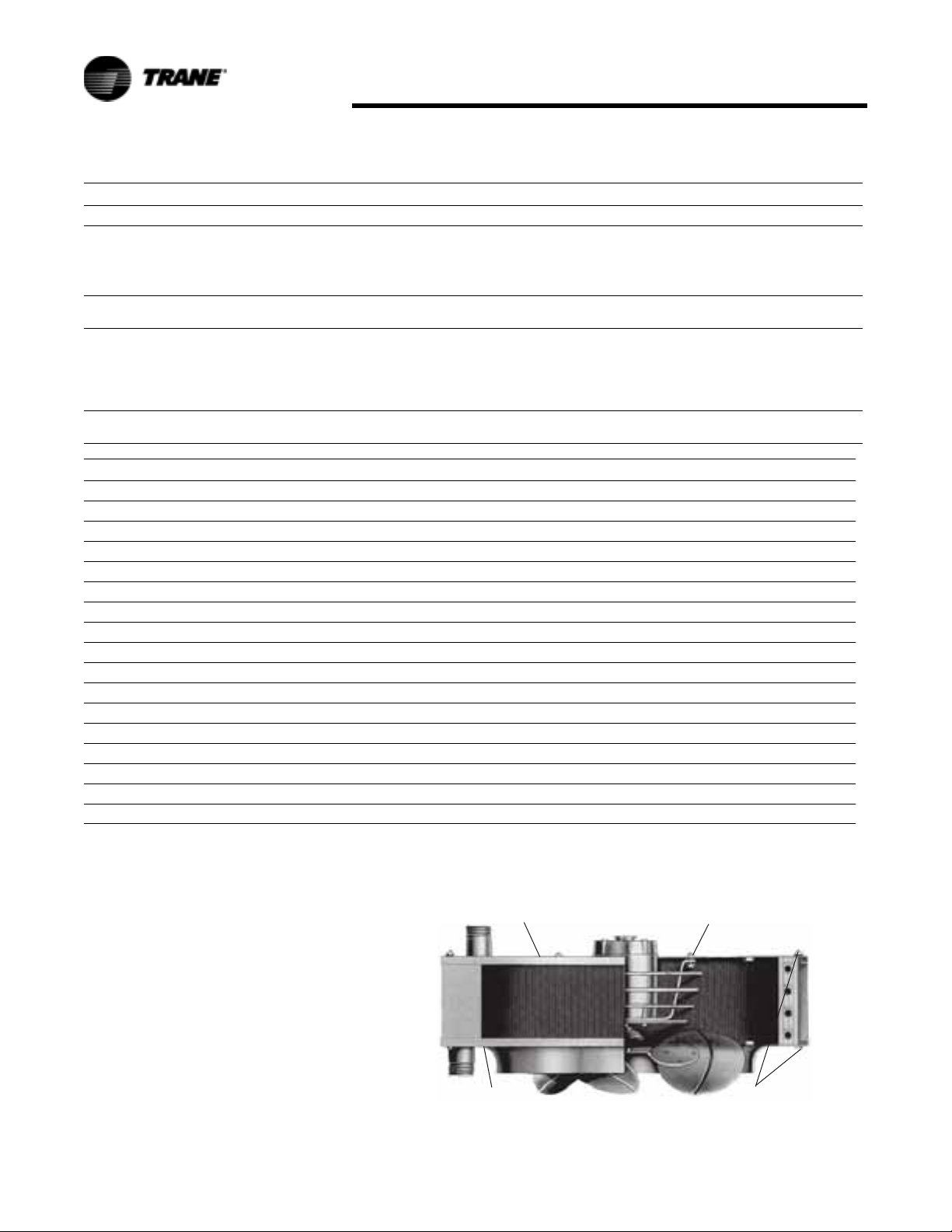
Maintenance
Table 42. Troubleshooting Guide
Symptoms Possible Cause(s) Corrective Action
A. Leaking coil 1. Frozen coil.
B. Poor output on steam 1. Check for air in coil.
C. Poor output on steam or hot water 1. No circulation of water through coil.
D. Noisy or vibrating unit 1. Damaged fan blade.
2. Defective coil.
3. Corrosion.
4. Leak in joint.
2. Lint on coil fins
2. Short cycling of motor.
3. Backward rotating motor.
2. Dirty fan blade.
Table 43. Unit Equipment Start-Up
Customer____________________________________________ Job Name & Number___________________________________
Pre-Inspection Information (with power off)
Type of equipment: Unit Heater
Serial Number________________________________________ Model Number________________________________________
Name Plate Voltage___________________________________ Name Plate Amperage_________________________________
Steam______________________________________________ Hotwater____________________________________________
1. Replace.
2. Replace.
3. Replace
4. Braze joint if joint is exposed where leak has
occurred.
1. Repair or replace thermostatic air vent.
2. Clean coil and fins. Check filter and clean.
1. Check circulation pump. Check for blocked tubes.
2. Check voltage and correct. Check for linted coil and
clean. Check for defective overload and repair or replace
motor.
3. On single phase motor replace motor. On three phase
motor, reverse two leads to change rotation.
1. Change fan blade.
2. Clean fan blade.
Questions/Checklist
Are all panels in place?
Has the unit suffered any external damage? If so, what:____________________________________________________________
Does the piping and electric wiring appear to be installed in a professional manner?
Has the piping and electric been inspected by the local authority having jurisdiction?
Is the supply properly sized for the equipment?
Were the installation instructions followed when the equipment was installed?
Have all field installed controls been installed?
Do you understand all the controls on this equipment?
the four panel mounting bolts. See
Additional "P" Model
Figure 58.
Instructions
Fan and Motor Assembly
For cleaning or maintenance
purposes, the fan and motor
assembly may be removed easily
from the Unit Heater. The motor is
attached to the fan guard which is, in
turn, mounted to the top or back
panel of the unit as shown in
Figure 58.
On Vertical Units, reach up through
the fan and remove the fan guard
mounting screws. Lower the motor,
fan and fan guard assembly down
through the fan outlet. If desired, the
top and bottom panels may be
removed from the coil by taking out
Top
Panel
Bottom
Panel
Figure 58. Cross Section View
Fan Guard
Mounting Screws
Panel Mounting
Bolts
56 UH-SVX01A-EN
Page 57

Warranty Info
LIMITED WARRANTY: S
Model
HORIZONTAL STEAM & HOT
WATER UNIT HEATERS
The Manufacturer warrants to the
original owner at the original
installation site that the Horizontal
Steam and Hot Water Unit Heaters
(the “Product”) will be free from
defects in material and workmanship
for a period not to exceed one (1)
year from startup or eighteen (18)
months from date of shipment from
the factory, whichever occurs first. If
upon examination by the
Manufacturer the Product is shown
to have a defect in material or
workmanship during the warranty
period, the Manufacturer will repair
or replace, at its option, that part of
the Product which is shown to be
defective.
This limited warranty does not apply:
a. if the Product has been
subjected to misuse or
neglect, has been
accidentally or intentionally
damaged, has not been
installed, maintained or
operated in accordance with
the furnished written
instructions, or has been
altered or modified in any
way.
b. to any expenses, including
labor or material, incurred
during removal or
reinstallation of the defective
Product or parts thereof.
c. to any workmanship of the
installer of the Product.
This limited warranty is conditional
upon:
a. shipment, to the
Manufacturer, of that part of
the Product thought to be
defective. Goods can only be
returned with prior written
approval from the
Manufacturer. All returns
must be freight prepaid.
b. determination, in the
reasonable opinion of the
Manufacturer, that there
exists a defect in material or
workmanship.
Repair or replacement of any part
under this Limited Warranty shall not
extend the duration of the warranty
with respect to such repaired or
replaced part beyond the stated
warranty period.
THIS LIMITED WARRANTY IS IN
LIEU OF ALL OTHER WARRANTIES,
EITHER EXPRESS OR IMPLIED, AND
ALL SUCH OTHER WARRANTIES,
INCLUDING WITHOUT LIMITATION
IMPLIED WARRANTIES OF
MERCHANTABILITY OR FITNESS
FOR A PARTICULAR PURPOSE, ARE
HEREBY DISCLAIMED AND
EXCLUDED FROM THIS LIMITED
WARRANTY. IN NO EVENT SHALL
THE MANUFACTURER BE LIABLE IN
ANY WAY FOR ANY
CONSEQUENTIAL, SPECIAL, OR
INCIDENTAL DAMAGES OF ANY
NATURE WHATSOEVER, OR FOR
ANY AMOUNTS IN EXCESS OF THE
SELLING PRICE OF THE PRODUCT
OR ANY PARTS THEREOF FOUND
TO BE DEFECTIVE. THIS LIMITED
WARRANTY GIVES THE ORIGINAL
OWNER OF THE PRODUCT SPECIFIC
LEGAL RIGHTS. YOU MAY ALSO
HAVE OTHER RIGHTS WHICH MAY
VARY BY EACH JURISDICTION.
LIMITED WARRANTY: P
Model
VERTICAL STEAM & HOT WATER
UNIT HEATERS
The Manufacturer warrants to the
original owner at the original
installation site that the Vertical
Steam and Hot Water Unit Heaters
(the “Product”) will be free from
defects in material and workmanship
for a period not to exceed one (1)
year from startup or eighteen (18)
months from date of shipment from
the factory, whichever occurs first. If
upon examination by the
Manufacturer the Product is shown
to have a defect in material or
workmanship during the warranty
period, the Manufacturer will repair
or replace, at its option, that part of
the Product which is shown to be
defective.
This limited warranty does not apply:
a. if the Product has been
subjected to misuse or
neglect, has been
accidentally or intentionally
damaged, has not been
installed, maintained or
operated in accordance with
the furnished written
instructions, or has been
altered or modified in any
way.
b. to any expenses, including
labor or material, incurred
during removal or
reinstallation of the defective
Product or parts thereof.
c. to any workmanship of the
installer of the Product.
This limited warranty is conditional
upon:
a. shipment, to the
Manufacturer, of that part of
the Product thought to be
defective. Goods can only be
returned with prior written
approval from the
Manufacturer. All returns
must be freight prepaid.
b. determination, in the
reasonable opinion of the
Manufacturer, that there
exists a defect in material or
workmanship.
Repair or replacement of any part
under this Limited Warranty shall not
extend the duration of the warranty
with respect to such repaired or
replaced part beyond the stated
warranty period.
THIS LIMITED WARRANTY IS IN
LIEU OF ALL OTHER WARRANTIES,
EITHER EXPRESS OR IMPLIED, AND
ALL SUCH OTHER WARRANTIES,
INCLUDING WITHOUT LIMITATION
IMPLIED WARRANTIES OF
MERCHANTABILITY OR FITNESS
FOR A PARTICULAR PURPOSE, ARE
HEREBY DISCLAIMED AND
EXCLUDED FROM THIS LIMITED
WARRANTY. IN NO EVENT SHALL
THE MANUFACTURER BE LIABLE IN
ANY WAY FOR ANY
CONSEQUENTIAL, SPECIAL, OR
INCIDENTAL DAMAGES OF ANY
NATURE WHATSOEVER, OR FOR
ANY AMOUNTS IN EXCESS OF THE
UH-SVX01A-EN 57
Page 58

SELLING PRICE OF THE PRODUCT
OR ANY PARTS THEREOF FOUND TO
BE DEFECTIVE. THIS LIMITED
WARRANTY GIVES THE ORIGINAL
OWNER OF THE PRODUCT SPECIFIC
LEGAL RIGHTS. YOU MAY ALSO
HAVE OTHER RIGHTS WHICH MAY
VARY BY EACH JURISDICTION.
Warranty Info
58 UH-SVX01A-EN
Page 59

Page 60

Tr a n e
A business of American Standard Companies
www.trane.com
For more information, contact your local Trane
office or e-mail us at comfort@trane.com
Literature Order Number UH-SVX01A-EN
Date 05/07
Supersedes UH-IM-2F (09/99)
Trane has a policy of continuous product and product data improvement and reserves the right to
change design and specifications without notice.
 Loading...