

Page 1
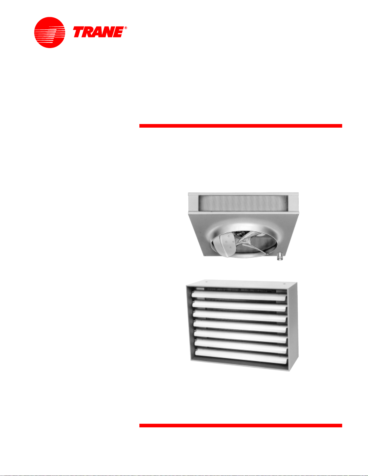
Propeller Unit
Heaters/Unitary
17.4 to 705.6 MBh
Two Versatile Models - Various Sizes
Easy Installation
October 1999
UH-PRC00 1 -EN
Page 2
Introduction
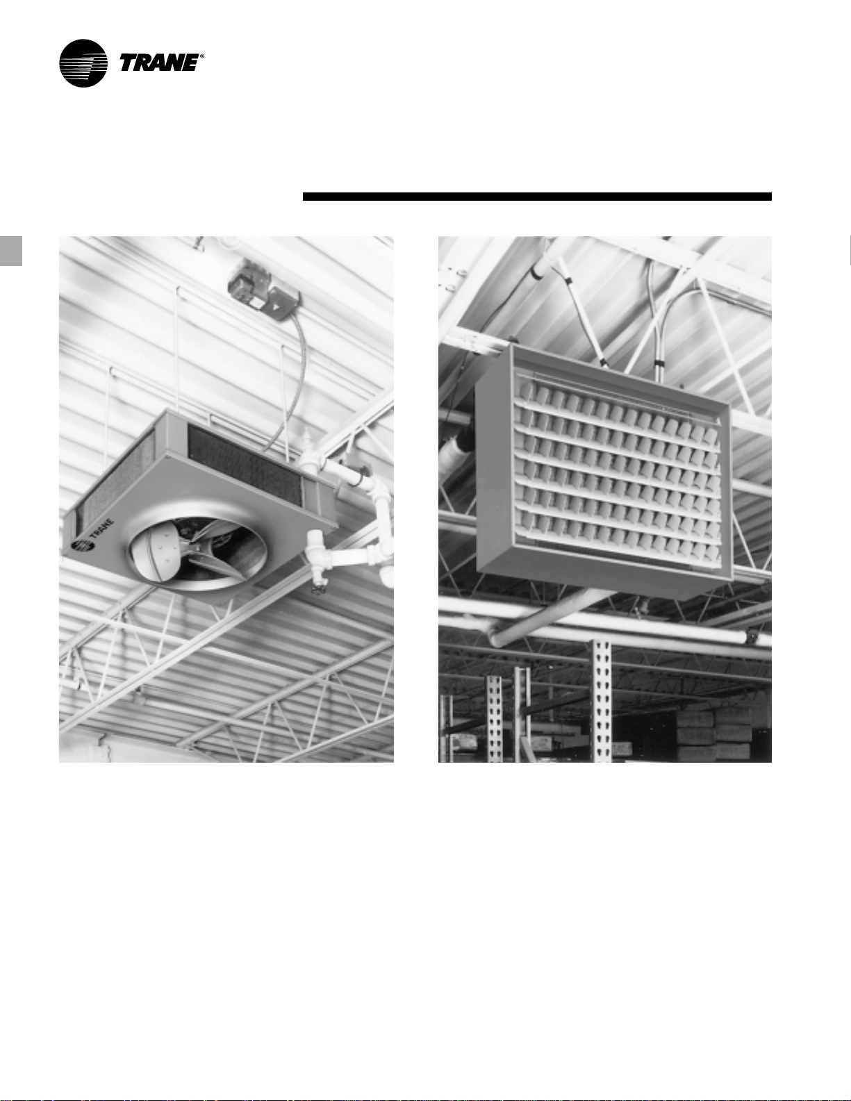
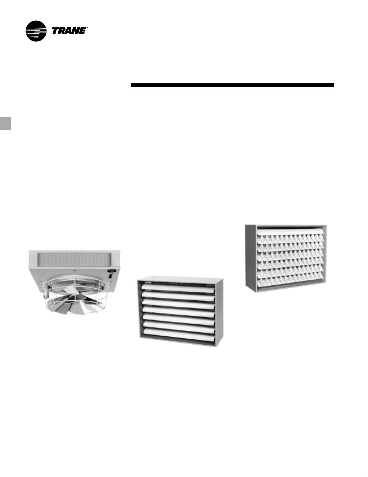
The Industrial Designed Model P Unit Heater
The square, compact design of the
Model P and rectangular Model S allow
easy handling and installation. In most
cases, only one person is needed to
carry a unit. And because both feature
compact Sigma-Flo
lightweight, making them easy to hoist
and put into place.
©American Standard Inc. 2000
®
fins they’re
The Clean-Line Appearance of the Model S Unit Heater
What’s more, the Model P can be stored
standing on end. This means several
units can be loaded on a single skid for
moving from one point to another. Trane
maintains a complete stock of both
Model P and S units that are available to
ship anywhere in the United States.
Y et, the benefits of this compact design
go beyond ease of installation. They
continue with attractive styling. The
Model S unit’s simple, clean-line
symmetry and the Model P unit’s classic
modern shape enhance any industrial
facility.
UH-PRC001-EN
Page 3

Contents
Introduction
Featur es and Benefits
Application Considerations
Selection Procedur e
Manual Selection Procedure
Model Number Description
P erformance Data
Electric P o wer
Dimension and W eights
Mechanical Specifications
2
4
8
11
19
21
23
44
47
50
UH-PRC001-EN
3
Page 4
Features and
Benefits
Two Units in One – the Versatile Model P
The T rane Model P can be quic kly field
converted from standard to low final
temperature PL design simply by
removing the unit’s patented knockout
air ports. This unique two-in-one design
allows the stocking wholesaler to cut
inventories in half and still meet most
customer application requirements.
T rane propeller unit heaters feature the
largest selection of standard sizes from
any line in the industry . In fact, vertical
Model P and horizontal Model S unit
heaters provide enough ‘of f-the-shelf’
selections to fit almost any application.
The versatile two-in-one Model P is
available in 15 sizes with capacities from
41 .3 MBh to 705.6 MBh while the
companion standard and bypass Model
The Space-Saving Model S
The Model S features attractive,
functional styling in a space-saving,
compact design.
In addition, T rane of fers an exclusive
bypass Model S design to meet low final
temperature, high cfm requirements. This
design uses a modified coil which allows
some of the air to flow over the top of the
coil without being heated. This cooler
band of air prevents the heated air from
rising so warm air throw is increased
while efficiency is improved.
S is available in 29 sizes with the
capacities from 17.4 MBh up to 404 MBh.
Both are designed for durability,
attractiveness and compactness. These
features combined with economical
operation, give strategically sized T rane
unit heaters an edge unmatched by any
other manufacturer.
Put Heat Where It’s Needed
Exclusive louver fin diffusers featured on
T rane unit heaters put heat where it’s
needed.
Patented Trane louver cone diffusers allow
directional flexibility of heated air.
Trane Model S features louve red disc har ge as
standard.
These patented T rane dif fusers provide
an unlimited combination of air diffusion
patterns as well as greater air throw
distance. In fact, when the louver cone
diffuser is added to the Model P, up to 45
percent greater air throw distance is
possible.
On Model S units, the combination of
horizontal louver blades and patented
vertical diffuser fins provide fourdirectional control of air delivery.
Optional low cost louver fin diffusers can
be adjusted to provide up to 25 percent
more air throw.
UH-PRC001-EN4
Page 5
Features and
Benefits
The Model S Coil
The Model S unit heater features a
unique single tube serpentine coil. This
compact, efficient coil has piping
connections at the back for added space
savings, convenience and appearance.
Model S single circuit coils use threaded
connectors at the back of the unit.
The Model P Motor
The Model P motor is mounted below
the top panel inside the heater casing.
This reduces unit height and permits the
unit to be installed closer to the ceiling
for added headroom.
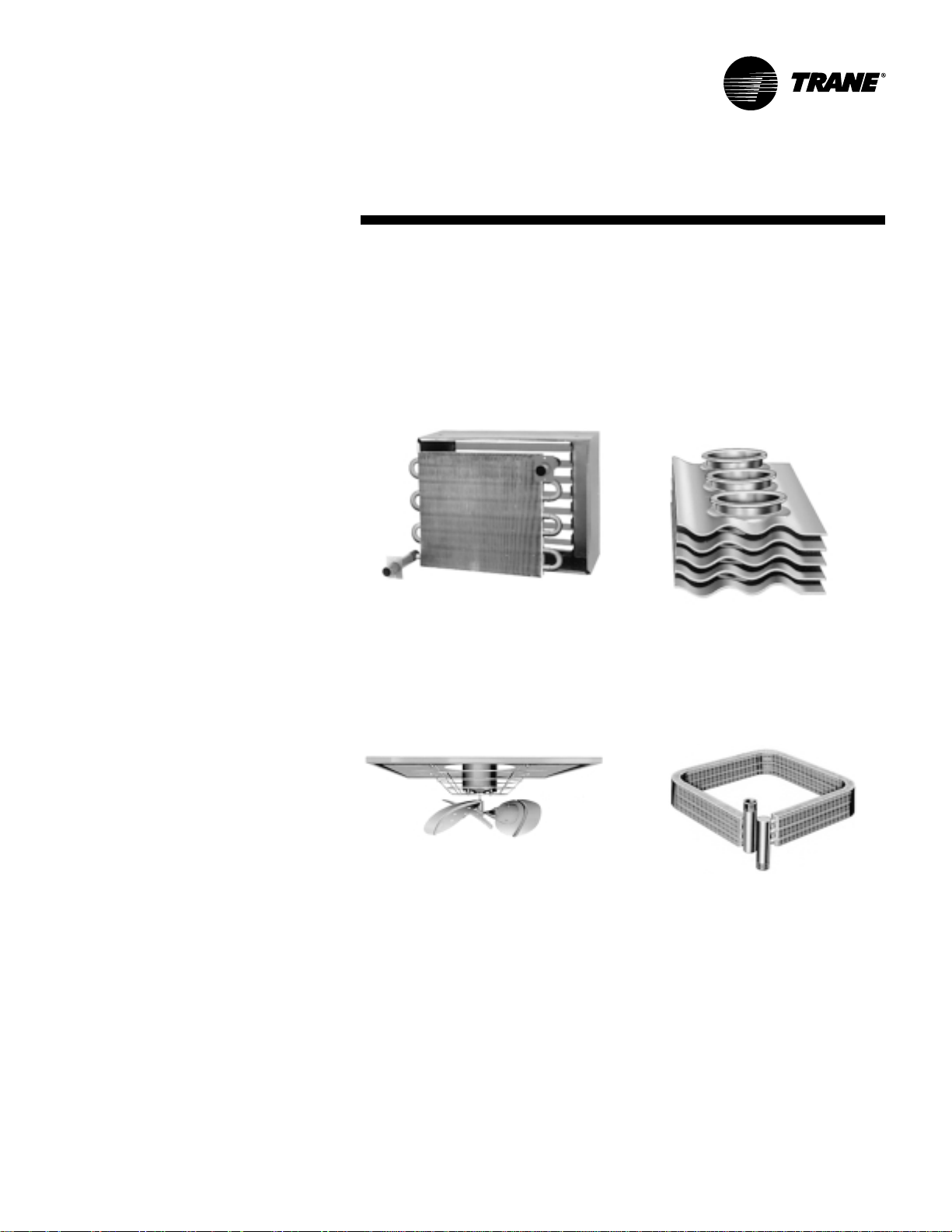
Compact Design
T rane designed Model S and P propeller
unit heaters for easy installation and low
maintenance. The Trane Sigma-Flo
design allows coil size to be reduced
while maintaining high capacity
performance equal to larger flat-fin coils.
Reduced size and weight makes T rane
unit heaters easy to handle and install.
Rectangular Draw -Thr u Coils
The Model P draw-thru coils use short
lengths of steel pipe threaded for supply
and return connections. These features
make piping connections much easier
for the installer.
®
fin
5UH-PRC001-EN
Page 6
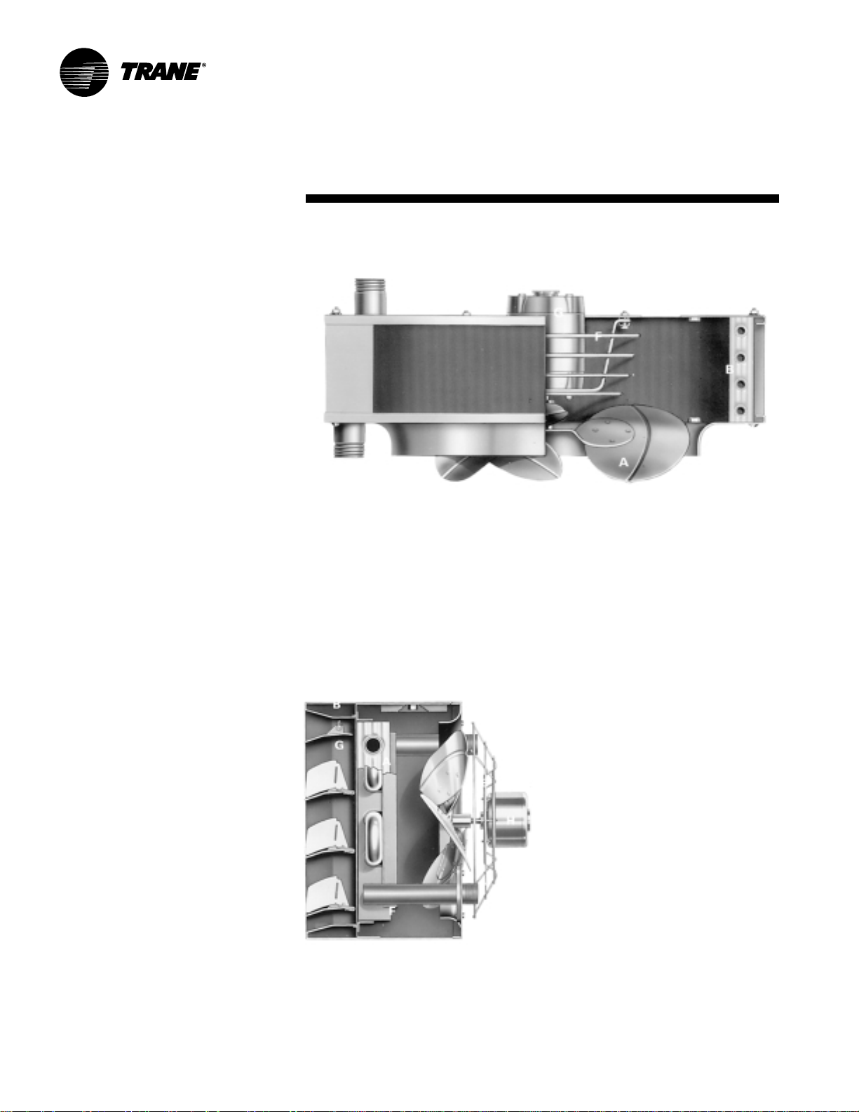
Model P
A
Exclusive T rane designed aluminum fans
provide smooth, nonsurge performance.
This, in turn, provides efficient, quiet
operation.
B
High performance Sigma-Flo
one-row coil have more efficient heat
transfer characteristics than flat fin coils.
C
Steel pipe headers are electrically
induction-brazed to coil tubes.
D
Top panel features knockout air ports
that, when removed, convert the unit
from standard to low final air
temperature, higher cfm operation.
E
Bottom plate provides drawn fan orifice
to assure smooth airflow.
F
Sturdy motor mounts absorb vibration
and anchor the motor securely .
G
Totally enclosed industrial designed
motors feature built-in overload
protection.
®
fins in a
Features and
Benefits
C
B
C
G
A
F
G
F
D
B
E
A
Model S
A
Exclusive, compact one-row
serpentine coil features high
performance Sigma-Flo fins.
B
One-piece wraparound casing with
picture-frame front panel combines
attractiveness with durability.
C
Heavy-gauge, one-piece bac k panel
can be easily removed for quick coil
access.
E
H
D
D
Rear connections and a compact
design provide more headroom than
conventional units.
E
Sturdy fan guard provides stronger
motor mount and quiet operation.
F
Unique coil supports anc hor coil
tubes without restricting expansion.
G
T rane horiz ontal louvers stay in
position with the exclusive louver
keeper design.
H
Totally enclosed industrial design
motors feature built-in overload
protection.
UH-PRC001-EN6
Page 7

Model P
Simple Hanger and Piping Connections
The Model P uses weldnut type hanger
connections, while the Model S uses a
nutsert type hanger connection. Hanger
rods screw easily into threaded anchor
points. Piping connections can be made
equally as easy. Model P units pro vide
threaded connections for inlet and outlet,
top and bottom.
Features and
Benefits
Model S
Fully A ccessible f or Easy Maintenance
Model S and P unit heaters are fully
accessible for maintenance. Only four
main bolts are needed to disassemble
the Model P. And when quick access is
needed, the Model S features a
one-piece back that can be easily
removed and slid over pipes without
breaking connections.
Motors can also be easily removed. Both
units feature totally enclosed motors
with thermal overload protection. As an
added benefit, Model P fan-motor
assemblies can be conveniently
removed from below through the fan
outlet.
External Couplings
The Model S provides threaded
connections for supply and return on the
back of its casing. In addition, bac k
connections reduce the amount of space
needed for installation.
7UH-PRC001-EN
Page 8

General Rules
In locating or spotting Trane Propeller
Unit Heaters – either the Model S
Horizontal or Model P Projection Unit
Heater – the following general rules
should be considered.
1 . Spot units at points of greatest heat
loss. Blanket outside doorways
effectively and provide ample coverage
for exposed window areas.
2. Units, especially in the case of the
Model S Horizontal Unit Heater , should
be arranged to blow toward or along
exposed walls, preferably striking the
wall at a slight angle so that the heated
air exerts a wiping effect along the w all.
Balance of units required to supply Btu
requirements should be spaced
strategically in balance of the area.
3. Unit heaters should be arranged to
blow into open spaces such as aisles and
not directly at any worker. An exception
to this rule involves the use of the Model
P Unit Heater equipped with the Louver
Cone Diffuser . This combination can be
used effectively over closely spaced bins
or machines without regard for open
space. But not even the Model P Unit
Heater with Louver Cone Diffuser should
be in such close proximity to the workers
to cause discomfort.
4. The T rane solid-state speed control will
provide maximum capacity flexibility and
quieter operation. Note that this speed
controller is available only on selected
models.
5. Mounting heights and distance of
throw recommendations as given
elsewhere in this catalog should be
carefully observed.
6. In the case of Model P Units, they
should be spotted so that they will most
effectively prevent stratification of
excessively warm air at the ceiling. By
carefully observing this rule, this type of
unit may be used between seasons to
tap waste heat at the ceiling and drive it
down to occupied zones, thereby
eliminating the need for added heat on
the system.
7. Do not spot units close to any
obstruction that will impede the full and
natural air delivery of the unit.
Typical Factory
In the typical industrial building, where
ceilings are high, Model P Unit Heaters
may be used without diffusers.
Application Considerations
Figure A C-1 – The floor plan and elevation of a typical industr ial building showing ho w a
Trane Unit Heater System will heat var ious par ts. Where ceilings are high in the main
manufactur ing section, l arg e Projection Heat ers without dif fusers are used. Where ceilings
are exceptionally high, as in cr ane bays, Model P Units with Louver Cone Dif fusers pr ovide
up to 45% greater thr ow t o top the “ceiling heat r eservoir.” Model P Units with half closed
Louver Cones blanket doorwa ys. Model S Units with Louver Fins blank et windows.
In plants where the ceilings are
exceptionally high, such as in crane bays
as illustrated in Figure AC-1, Model P
Units with Louver Cone Diffusers can
increase the downward projection of
heat by as much as 45% over units
without diffusers.
Model P Units with the Louver Cone
Diffusers can also be used to blanket
doorways effectively, as shown in Figure
AC-1 by simply adjusting half of the
louvers vertically, and half closed.
Model S horizontal-type units are ideal
for mounting in plant areas where
ceilings are low. In fact, due to the
extremely small height of the Model S,
and because all piping connections are
made at the back of the unit, the Model S
provides a greater saving in headroom
than other horizontal unit heater makes.
As illustrated in Figure AC-1, the Model S
Unit Heaters may be mounted
conveniently from the ceiling, or from
building structural supports and beams.
With Louver Fin Diffusers, they are ideal
for blanketing windows, and Model S
“Bypass” Unit Heaters, provide further
flexibility of application where greater
throw and more effective distribution of
air in the living zone is required.
UH-PRC001-EN8
Page 9
Application
Considerations
General Notes
The following general notes on piping
propeller unit heaters are presented
based on competent engineering and
installation practice:
1 . Suspend unit heaters securely with
provisions for easy removal.
2. Make certain units hang level vertically
and horizontally .
3. Provide for expansion in supply lines
(note swing joints in suggested piping
arrangements).
4. Provide unions adjacent to unit heaters
in both supply and return laterals. Also
provide shut-off valves in all supply
laterals.
5. Use 45' angle runoffs from all supply
and return mains.
6. Provide at least 7" (more if necessary)
clearance above tops of Model P
Projection Unit Heaters. Motors are
removable from below on all sizes.
It is desirable to form dirt poc kets with
pipe of the same size as the return
tapping of the unit heater. Pipe in the
branch-of f should be the same siz e as the
tapping in the trap. Beyond the trap, the
return lateral should be increased one
size to the return main.
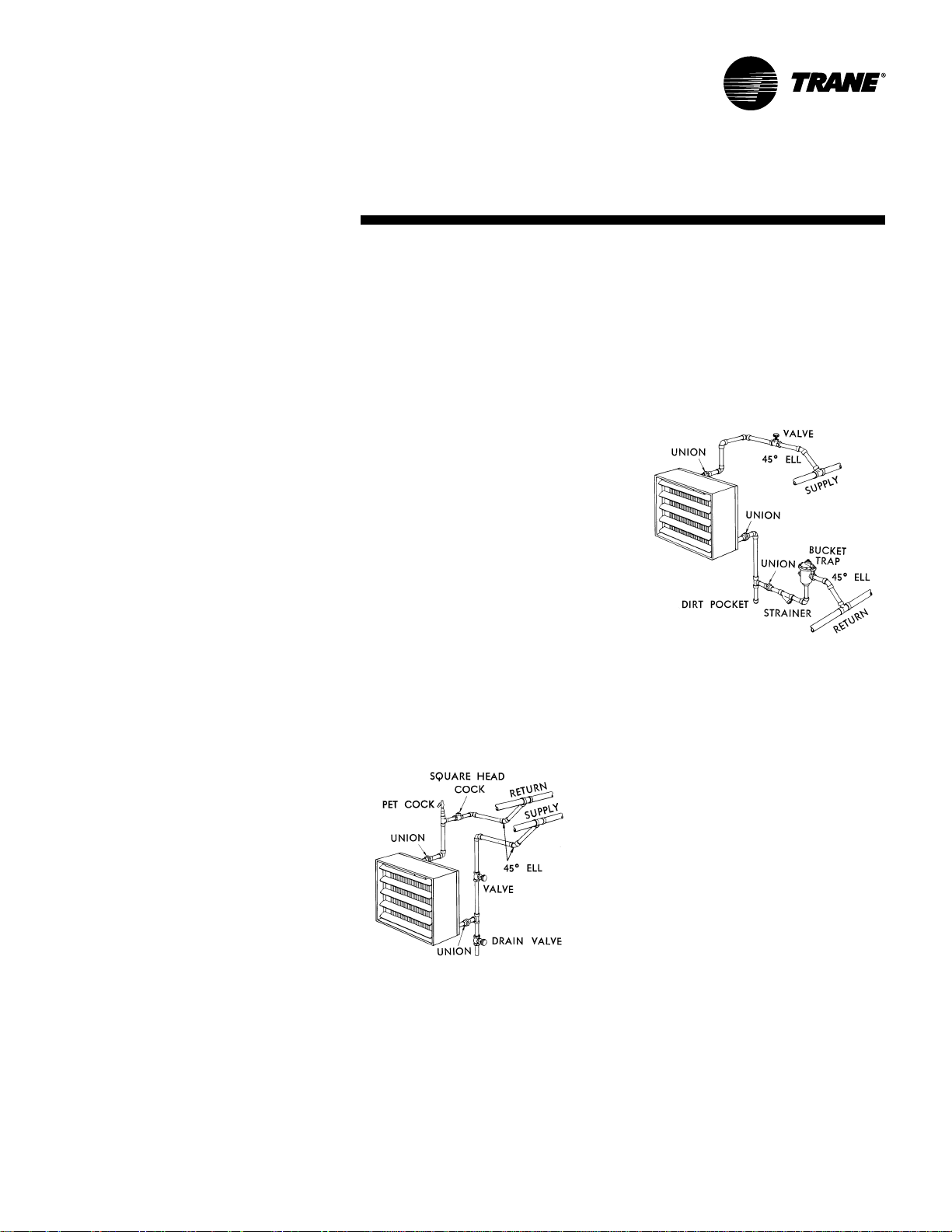
Hot Water System – Using Cir culating
Pump
Overhead supply and return mains are
used with bottom connections to mains.
Manual vent (pet cock) is used at high
point on return main. Automatic air vent
may be substituted if desired. Refer to
Figure AC-2.
Figure AC-3
High Pressure Steam Syst em
Overhead supply main is used with
lower return main. Where steam
pressure fluctuates over a wide range, a
swing chec k valve should be placed in
the return lateral between strainer and
bucket trap to prevent reverse flow of
condensate of flash steam when
pressure drops suddenly. Top of buc ket
trap must be located below return outlet
of coil for complete drainage of
condensate. Refer to Figure A C-3.
Figure AC-2
9UH-PRC001-EN
Page 10
Application
Considerations
Figure AC-4
Table AC-1 - Model P Coil F ace Area
Unit Numbers Fin Area In Sq. Ft
42-P & P-L 1 .20
64-P & P-L 1 .49
80-P & P-L 1 .98
102-P & P-L 3.28
122-P & P-L 3.28
146-P & P-L 3.88
166-P & P-L 4.85
202-P & P-L 4.85
252-P & P-L 6.52
280-P & P-L 6.52
336-P & P-L 6.52
384-P & P-L 7 .82
500-P & P-L 8.72
600-P & P-L 11.63
720-P & P-L 13.08
Table AC-2 - Supply and Retur n Sizes at 2 Psi
Capacity In Lbs. Of Size Of Size Of
Steam Per Hour Supply Gravity Return
39 1” 3/4”
87 1 1/4” 3/4”
134 1 1/2” 1”
272 2” 1 1/4”
449 2 1/2” 1 1/2”
822 3” 2”
Note: This table is based on 1/2 lb. drop per 100 ft. of
equivalent run of steam line and approximately 1/4 lb. drop
in the return line per 100 ft. increase steam run-outs one
size if more than 8 ft. long.
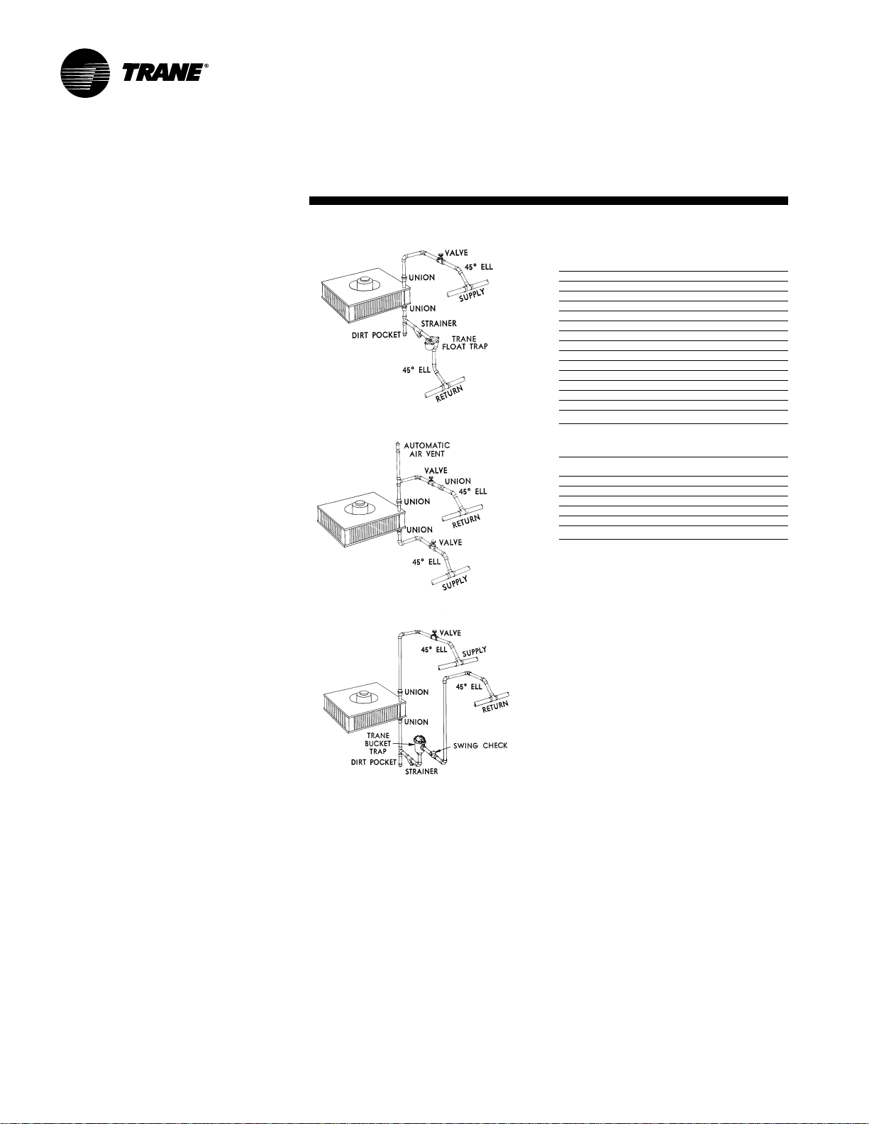
Figure AC-5
Figure AC-6
V apor or V acuum S ystem
Lower supply and return mains are used.
Piping should be similar to that used with
overhead supply main if it is separately
vented and trapped. Bottom supply for
steam mains may be used if steam is dry.
Refer to Figure A C-4. F or proper pipe size,
refer to T able AC-2.
Hot Water System with Cir culating
Pump
Lower supply and return mains are
shown. Overhead supply and return
main connections, similar to those in
Figure AC-2 may be used. The automatic
air vent is shown here but a manual vent
(pet cock) may be substituted. Refer to
Figure AC-5.
High Pressure Steam S ystem
Overhead supply and return mains are
used. The top of the bucket trap must be
located below bottom return outlet of coil
for complete drainage of condensate.
Refer to Figure A C-6.
UH-PRC001-EN10
Page 11

Selection Pr ocedure
Trane Propeller Unit Heaters
Both Model S and Model P Propeller
Unit Heaters are ideally suited to such a
wide variety of installations that there
can be no hard and fast rules regulating
their selection.
In determining the type and size of the
units for any building, the following
points are generally considered:
BTU Requirements
While the choice of units depends upon
several important factors, the total Btu
requirement is usually determined first.
In calculating heat loss, methods as
recommended by the ASHRAE Guide
may be used, or any other procedure
which is known to be acceptable.
Type of Building
Once the total Btu requirement is known,
the type of building together with its
architecture and its purpose is
considered.
In the many cases where a combination
of space characteristics is found, a
combination of Model S and Model P
Unit Heaters may be used to create the
most satisfactory heating system.
The Model P Unit Heater has the natural
ability to tap the reservoir of heated air
which collects at the ceiling level and
return it to active service in the floor
zone.
The Model P can be used on either high
or low ceilings. From high mounting
positions the Model P will allow ample
clearance for moving objects and can
project heat down into occupied areas
regardless of obstacles which would
restrict the flow of air from horizontal
units.
From low mounting positions the Model
P, with proper diffusion, can be used
without disturbing nearby occupants
with direct blasts of high velocity heated
air, or requiring return lines so low as to
leave insufficient head room.
The superior horizontal action of the
Model S, on the other hand, is ideal for
creating a wiping effect of warm air
along exposed walls which neutraliz es
drafts at their source, beaming heat
down narrow aisles and production
lines, and blanketing large windows,
doors and other points of high heat loss.
Spacing of Units
It is the usual practice to divide the
building into areas with like exposures,
or in relation to heat load distribution
desired.
In general, Model S Unit Heaters may
be selected for buildings where direct
horizontal air currents are desired and
where there are no obstacles to
interrupt the flow of air from the
heaters.
Model P Unit Heaters are successfully
used where high or low mounting
heights are required and should
ordinarily be specified with diffusers,
depending upon the mounting height
and application.
Mounting Heights
maximum
The
height is determined by the outlet
temperature of the air, the outlet
velocity, the cfm for whic h the heater is
designed, and if a diffuser is used – the
setting of its blades.
The higher the outlet temperature of
the air, the more dif ficult it is to force it
down into the living zone.
The cfm also affects the mounting
height as a large volume of air will
travel farther than a small volume
under the same initial conditions of
temperature and velocity.
In the preliminary planning stages, it is
well to remember that the lowest
possible mounting height is desirable in
order to get the most heat down to the
floor line and to allow the greatest
possible diffusion adjustment to
provide tailor-made distribution for
each area.
effective mounting
In providing for the use of diffusers
please remember, adjustment of a
Louver Cone Diffuser to deflect the air
toward the horizontal immediately
lowers the mounting height limit.
Adjustment for lateral deflection with
the Louver Fin Diffuser shor tens the
distance of throw.
Diffusion
The use of T rane L ouver Cone or
Louver Fin Diffusers influences the
selection of units in two principal ways:
First: It is seldom necessary to install
oversized heaters to extend the
maximum effective mounting height of
the Model P or the distance of throw of
the Model S. Conversely, Trane Diffusers
enable extremely low mounting since the
adjustable blades direct heat where it is
wanted without creating uncomfortable
hot spots near the units.
Second: Af ter the original selection has
been made, units may be located with
confidence because adjustments in heat
distribution are possible to
accommodate future changes or
unforeseen draft conditions.
Air Changes
Better diffusion and more even
temperatures can be maintained in a
heated space when the rate of air
recirculation through the heaters is
relatively high. For buildings where large
numbers of people are engaged, it is
desirable to provide for a greater number
of air changes than for sparsely occupied
areas.
A greater number of small units are used
where wide diffusion and even
temperatures are necessary. A few
centrally located units of large capacity
would be used where there are few
occupants.
Comfort Conditions and Econom y
Air circulation, diffusion and spacing of
units are closely related to economy and
comfort in the selection of unit heaters.
The more units used to provide the
required number of Btu’s, the more
comfortable will be the conditions for
personnel. On the other hand, a few
large units can be selected to provide
plenty of heat at low first cost, but may
be slower in response and thorough
distribution of heat.
Here again, adjustable diffusion
equipment can go a long way toward
saving the buyer first cost expense while
still providing completely satisfactory
comfort conditions.
11UH-PRC001-EN
Page 12

Selection
Pr ocedure
Formula
The following formula is used to arrive at
final air temperature volume when 70 F
(Standard Air Basis) is known or vice
versa:
Cfm at final temp. =
Cfm at 70 F x
Cfm at 70 F =
Cfm final air x
Determining Special Steam Capacities
Where capacity of the unit under
standard conditions is known – 2 lbs.
steam, 60 F entering air – and it is
desired to know the capacity of this
same unit under different steam and air
conditions, follow instructions given in
Example 1 below.
Where a set of conditions is given – Btu,
temperature rise, final temperature, cfm,
steam pressure available, etc. Refer to
Example 2.
Useful Data
Btu
= Sq. ft. of radiation (EDR)
240
Sq. ft. of radiation =Lbs. of condensate
Btu
Latent heat
460 + Final temp.
460 + 70
460 + 70
460 + Final temp.
4 per hour
= Lbs. of water per hour
Example 1
Given: Model 60S Horizontal Propeller
Unit Heater with a rated capacity of
60,500 Btu at 2 lbs. steam with 60 F
entering air.
Desired: Capacity of this unit using
15 lbs. steam and 40 F entering air.
Under 40 F and across from 15 lbs. in
SP-2, page 14, we find the factor 1.34.
60,500 x 1.34 = 81,070 Btu per hour .
Equivalent Direct Radiation
If working in EDR, rather than Btu,
multiply the EDR by the same factor in
the same way. Thus:
252 (From Table 3) x 1.34 =
81,070
338 sq. ft. or
Determining Amount of Condensate
To determine the amount of condensate,
divide the capacity in BTU by the latent
heat of steam:
81,070
945
945 = Latent Heat of Steam at 15 psi.
240
= 86 lbs per hour.
(See Table SP -9, page 18.)
Determining Final Temperature
Final temperature of air leaving T rane
Unit Heaters may be determined as
follows:
Inlet Air T emp. + Btu rating = FinalTemp
Cfm at 70F x 1 .085
Inlet Air Temp. 40F + 81,070 = FinalTemp
815(from table 3) x 1 .085
Example 2:
Problem: A Trane Model S Horizontal
Unit Heater is desired to deliver 280,000
Btu per hour in a garage where
ventilation is required. Entering air
temperature is 40 F. Steam at 30 lbs.
pressure is available. Temperature to be
maintained is 70 F.
Solution: Under 40 F and across from 30
lbs. in Table SP-2 page 1 4, find the factor
1 .51.
Equivalent capacity of required unit at
2 lbs. steam 60 F entering air is
Required Btu per hour = 280,00 =185,400
F 1 .51 Btu
From Table SP -3, page 15, select a
Number 186S Unit Heater with a
capacity of 185,200 Btu per hour with
standard coil, and at 2 lbs. steam and 60
F entering air.
Cfm x Temp. rise x 1.085 = Btu.
Specific heat of air (70 F) = .241
Specific weight of one cubic foot of air
(70 F) =.075.
Cfm x 60 = cfh.
Therefore, .241 x .075 x 60 = 1 .085
The capacity of this unit at 30 lbs. steam
and 40 F entering air is
1 .51 x 1 85,200 = 279,650 Btu per hour.
Surplus Capacity
While the ventilation load is being
handled, any air entering the space over
the desired room temperature should be
considered in the heating calculations.
This surplus capacity can be found by
multiplying the difference between the
final temperature leaving the heater and
the room temperature to be maintained
by 1 .085 and that by the cfm. That
amount of heat can be used to offset
heat losses.
UH-PRC001-EN12
Page 13

Selection
Pr ocedure
Model S Nomenclature
UHS A 0 1 8 S 2 E A A 1 T A W D A D B E
123 4 5 6 7 8 9 10 11 12 13 1 4 1 5 1 6 17 18 19 20 21
Digits 1,2,3 – Product T ype
Digit 4 – Development Sequence
Digits 5,6,7 – Unit Size
Digit 8 – Coil T ype
S = Hot Water or Steam
W= Hot W ater with Turbulators
Digit 9 – Fin Series
2 = 132
8 = 108
Digit 10 – Design Sequence
Digit 1 1 – Tube Material
Digit 12 – Fin Material
Digit 13 — Voltage
Digit 14 — Motor Type
Digit 15 — Motor Mount/Fan Guar d
Digit 16 — Special Coatings
Table SP-1 – Max. Mounting Heights and Distance of Throw for Model S Units
(Based on 2 Lbs. Steam Pressure 60 F Entering Air)
Unit V elocity CFM (F) Height Diffuser Maximum Throw
18-S 162 280 117 8 12 15
20-S2 186 318 118 8 15 18
38-S 319 544 126 9 18 22
42-S 347 590 125 9 20 25
60-S 343 815 129 9 22 27
70-S 454 1 1 00 1 17 10 28 35
90-S 382 1214 127 1 1 28 35
100-S 47 6 1535 118 12 28 35
126-S 41 1 1760 126 13 32 40
168-6 452 2380 127 14 40 50
186-S 528 2808 121 14 45 56
230-S 431 3300 124 15 40 50
260-S 529 4100 118 15 50 62
320-S 442 4480 127 15 50 62
354-S 550 5660 118 15 60 75
400-S 583 6017 122 15 65 80
19-S2 220 390 106 8 18 22
31-S 359 635 104 8 20 25
45-S 363 897 107 9 25 31
53-S 439 1090 105 10 28 35
69-S 407 1337 108 12 30 37
77 -S 458 1510 107 13 32 40
91-S 394 1740 108 14 32 40
127-S 448 2440 108 15 40 50
137-S 495 2700 107 15 45 56
181-S 430 3392 109 15 42 52
207-S 514 4059 107 15 48 60
243-S 439 4607 108 15 55 68
273-S 536 5644 105 15 60 75
Outlet Temp. Mounting Without Set for
Final With Louver Fin
Maximum Throw
Digit 17 — Diffuser
Digit 18 — Manual Starter
Digit 19 — Speed Controller (1 15/60/1
standard motors)
Digit 20 — Thermostats
Digit 21 — Subbase
Digit 22 — Voltage
13UH-PRC001-EN
Page 14

Selection
Pr ocedure
Model S
Maximum mounting heights for Model
S Unit Heaters are given in Table SP-1.
When equipped with standard Louver
Fin Diffusers the distance of throw may
be increased as much as 25% by “toeing-
in” the ver tical blades.
Distance of throw
decreases in proportion to the amount of
deflection given the airstream to either
side of the heater.
Mounting the unit at or below maximum
mounting height will insure that heated
air reaches the living zone.
Model P
Maximum mounting heights for Model P
Unit Heaters are given in Table SP-1 0,
page 19. These distances are figured
from the floor line to the bottom plate of
the unit heater.
Where ceilings are unusually low, a
nearly horizontal flow of air can be
obtained by equipping these units with
Louver Cone Diffusers. The individually
adjustable blades of the Louver Cone
permit an infinite variety of adjustments
to meet any on-the-job problems. By
setting the blades vertically to straighten
the airstream, as much as 45% increase
in throw can be obtained.
Table SP-2 – Factors for Det er mining Steam Capacity of Model S Horizontal Unit Heaters at Various Pressures and Temperatures
Through 15 1.80 1 .71 1.61 1.53 1.44 1.34 1 .28 1.1 9 1.1 2 1.04 0.97 0.90
Notes:
To determine the Btu per hour capacity of a Model S Horizontal Unit Heater at any steam pressure and entering air temperature multiply rated capacity at 2 psig steam 60 F entering air (Table
SP-3) by factor from above table. Factors in italics: Units should not be operated when entering air is below freezing at steam pressures below 10 psig.
T able Based on 2 PSIG and 60 F Entering Air
Steam T emperature of Entering Air (F)
Pressure PSIG -10 0 10 20 30 40 50 60 70 80 90 100
Blow- 10
Type 20 1.86 1 .77 1.68 1.58 1.50 1.42 1 .33 1.25 1 .17 1.1 0 1.02 0.95
0
2
5
30 1.97 1.87 1.78 1.68 1.60 1.51 1 .43 1 .35 1.27 1.1 9 1.12 1.04
40 2.06 1 .96 1.86 1.77 1.68 1.60 1 .51 1.43 1 .35 1.27 1.19 1.12
50 2.13 2.04 1.94 1 .85 1.76 1.67 1.58 1.50 1 .42 1.34 1.26 1.19
60 2.20 2.09 2.00 1.90 1 .81 1.73 1.64 1 .56 1.47 1.39 1.31 1.24
70 2.26 2.16 2.06 1.96 1 .87 1.78 1.70 1 .61 1.53 1.45 1.37 1.29
75 2.28 2.18 2.09 1 .99 1.90 1.81 1 .72 1 .64 1 .55 1.47 1.40 1.32
1.54 1.45 1.37 1.27 1 .1 9
1.59 1.50 1.41 1.32 1.24
1.64 1.55 1.46 1.37 1.29
1.73 1.64 1.55 1.46 1.38
1.11 1.03 0.96 0.88 0.81 0.74 0.67
1 .16 1.08 1 .00 0.93 0.85 0.78 0.71
1.21 1.13 1 .05 0.97 0.90 0.83 0.76
1.29 1.21 1 .13 1 .06 0.98 0.91 0.84
UH-PRC001-EN14
Page 15

Selection
Pr ocedure
Table SP-3 – Model S Horizontal Unit Heat er Steam Capacities
2 Lbs. Steam 60 F Entering Air Temp
Size HP RPM P er Hour EDR Lbs Per Hr T emp Air Basis Velocity Weight
18-S 1/50
20-S2 1/50
38-S 1/20
42-S 1/20
60-S 1/20
70-S 1/8
90-S 1/8
100-S 1/8
126-S 1/6 1 100 125,700 525 130 126 1760 411 100
168-8 1/6 1100 172,000 716 178 127 2380 452 145
186-S 1/4 1 1 00 185,200 775 191 121 2808 528 145
230-S 1/4 1 100 229,700 957 237 124 3300 431 190
260-S 1/2 1 100 256,300 1070 265 118 4100 529 195
320-S 1/2 1 1 00 324,000 1350 335 127 4480 442 245
354-8 1/2 1 100 355,500 1480 368 118 5660 550 250
400-S 3/4 11 45 404,073 1684 418 122 6017 583 260
Notes:
1. Constant speed units are rated at capacities shown in regular type: Capacities in italic faced type apply only to
units with multi-speed motors.
2. Capacities based on 2 psi steam and 60 F entering air.
Motor Motor BTU Condensate Final CFM 70 F Outlet Oper.
Standard Units
1050 17,400 72 18 1 17 280 162
950 16,600 69 17 1 18 266 154 40
800 13,900 58 14 1 18 224 130
1050 20,000 84 21 118 318 186
950 19,000 79 20 120 298 173 40
800 15,500 64 17 120 250 145
1550 38,700 162 40 126 544 319
1300 35,900 150 37 130 472 279 40
1100 32,700 136 33 135 399 238
1550 41,600 174 43 125 590 347
1300 38,000 158 39 130 495 294 40
1100 34,700 145 35 136 420 251
1550 60,500 252 64 129 815 343
1300 56,000 234 58 133 706 300 55
1100 51,200 214 52 139 597 256
1550 68,200 285 70 117 1 100 454
1300 64,900 271 67 123 953 397 60
1100 59,700 248 61 128 806 339
1550 87 ,600 366 90 127 1214 382
1300 81,200 340 84 131 1053 334 75
1100 74,200 310 76 137 891 285
1550 96,000 400 99 118 1535 476
1300 91,500 380 94 123 1330 417 85
1100 84,000 350 86 128 1 126 356
15UH-PRC001-EN
Page 16

Selection
Pr ocedure
Table SP-4 – Model S Horizontal Unit Heat er Steam Capacities con’t
2 Lbs. Steam 60 F Entering Air T emp
Size HP RPM P er Hour EDR Lbs Per Hr Temp Air Basis Velocity Weight
19-S2 1/25
31-S 1/20
45-S 1/20
53-S 1/8
69-S 1/8
77-S 1/8
91-S 1/6 1 100 91,000 380 94 108 1740 394 95
127-S 1/6 1100 125,800 524 130 108 2440 448 135
137-S 1/4 1 100 135,800 567 140 107 2700 495 135
181-S 1/4 1100 180,700 755 187 109 3392 430 180
207-S 1/2 1100 206,900 863 214 107 4059 514 185
243-S 1/2 1100 238,700 995 248 108 4607 439 230
273-S 1/2 1100 272,200 1135 283 105 5644 536 235
Notes:
1. Constant speed units are rated at capacities shown in regular type: Capacities in italic faced type apply only to units with multi-speed motors.
2. Capacities based on 2 psi steam and 60 F entering air.
Motor Motor BTU Condensate Final CFM 70 F Outlet Oper.
Low Final Temp. “Bypass” Units
1050 19,300 80 20 1 06 390 220
950 18,300 77 19 1 08 360 205 40
800 16,300 68 17 11 0 300 173
1550 30,400 127 31 104 635 359
1300 27,800 116 29 109 520 302 40
1100 25,300 106 26 1 1 2 450 257
1550 45,800 191 47 107 897 363
1300 41,300 173 43 1 1 2 740 304 55
1100 37,300 156 39 116 630 259
1550 53,300 223 55 105 1090 439
1300 50,200 209 52 109 940 383 55
1100 46,200 192 48 1 14 795 327
1550 69,400 290 72 108 1337 407
1300 63,400 264 66 112 1125 346 70
1100 57,600 240 60 116 955 295
1550 76,600 320 79 107 1510 458
1300 71,700 299 74 111 1304 300 80
1100 65,800 274 68 1 1 6 1100 341
UH-PRC001-EN16
Page 17

Selection
Pr ocedure
Table SP-5 – Model P Projection Unit Heater Steam Capacities
2 Lbs. Steam 60 F Entering Air T emperature
Motor Motor BTU Condensate Final CFM 70 F CFM at Outlet Oper.
Size HP RPM Per Hour EDR Lbs Per Hr Temp. Air Basis Final Temp. Velocity Weight Lbs.
42-P 1/25 1550 41,300 172 43 124 595 660 877 30
64-P 1/20 1550 65,500 273 68 121 989 1085 1005 35
80-P 1/20 1550 80,600 336 83 122 1200 1320 1220 40
102-P 1/8 1070 101,800 424 106 123 1490 1635 980 55
122-P 1/6 1070 124,400 518 129 124 1790 1970 1170 55
146-P 1/6 1 070 152,000 633 157 123 2220 2440 1045 80
166-P 1/6 1 070 173,000 720 179 121 2620 2870 1230 80
202-P 1/4 1070 210,200 838 208 118 3200 3490 1495 85
252-P 1/4 1070 249,800 1040 260 115 4180 4550 1205 135
280-P 1/2 1070 283,800 1180 294 1 1 9 4430 4840 1275 135
336-P 3/4 1120 333,400 1390 345 1 19 5210 5690 1500 135
384-P 3/4 1120 386,000 1610 400 1 18 6140 6700 1770 175
500-P 1-1/2 1120 496,000 2070 514 117 8020 8750 1640 250
600-P 1-1/2 1120 585,000 2440 605 1 17 9450 10,300 1 930 260
720-P 3 1 120 705,000 2940 729 1 1 9 1 1,000 12,020 2250 325
42-P-L 1/25 1150 34,800 145 36 108 668 716 950 30
64-P-L 1/20 1550 57 ,200 238 59 104 1200 1280 1 1 90 35
80-P-L 1/20 1550 68,000 283 71 106 1360 1455 1350 40
102-P-L 1/8 1070 85,400 356 89 108 1640 1760 1050 55
122-P-L 1/6 1070 111,000 462 115 107 2180 2330 1390 55
146-P-L 1/6 1070 125,800 524 130 109 2360 2530 1080 80
166-P-L 1/6 1070 149,000 620 154 107 2920 3130 1340 80
202-P-L 1/4 1070 176,800 736 183 108 3390 3640 1560 85
252-P-L 1/4 1070 214,900 895 224 104 4500 4800 1270 135
280-P-L 1/2 1070 251,800 1 050 260 106 5040 5380 1420 135
336-P-L 3/4 1120 291,000 121 0 302 107 5700 6100 1610 135
384-P-L 3/4 1120 344,000 1430 356 108 6600 7080 1870 175
500-P-L 1-1/2 1120 428,000 1785 446 102 9380 9940 1860 250
600-P-L 1-1/2 1120 515,000 2140 533 106 10,300 11,000 2060 260
720-P-L 3 1 120 620,000 2580 642 108 1 1,900 12,750 2380 325
Notes:
Constant speed units are rated at capacities shown in regular type; capacities in italic faced type apply only to units with multi-speed motors.
To determine BTU per hour capacities at various steam pressures and entering air temperatures, use conversion factors from Table SP-7, page 18.
Final temperatures at new conditions can be calculated by applying basic formula.
1150 33,600 140 35 131 436 495 658
1150 52,800 220 55 129 706 785 727
1150 65,100 271 67 130 858 954 894
850 87,900 366 91 129 1 1 80 1315 783
Low Final Temperature Models - Standard Model P Units With All Air P or ts Open
1150 26,000 108 27 1 11 470 506 672
1150 45,800 191 48 109 862 925 858
1150 55,000 229 57 1 11 995 1070 992
850 71,200 296 74 111 1290 1390 827
Standard Models
Table SP-6 – Maximum Spread (Ft.)
Unit No. 42P 64P 80P 102P 122P 146P 166P 202P 252P 280P 336P 384P 500P 600P 720P
Spread (Ft.) 15 17 20 24 26 27 28 32 35 37 45 50 54 57 60
Note:
The “spread” is the diameter of the comfort zone at floor level, projected by the Model P unit without the louver cone diffuser, based on two pounds steam pressure and 60 F entering air.
17UH-PRC001-EN
Page 18

Selection
Pr ocedure
Model P Nomenclature
Digit 15 – Fan Guard
UHP A 0 4 2 P 4 C A A 1 T A R C A D B E
123 4 5 6 7 8 9 10 11 12 13 14 15 16 17 18 19 20 21
Digits 1,2,3 – Product T ype
Digit 4 – Development Sequence
Digits 5,6,7 – Unit Size
Digit 8 – Coil T ype
Digit 9 – Fin Series
Table SP-7 – Factors F or Deter mining St eam Capacity Of Model P Projection Unit Heat ers At Various Pressures And Temperatur es
Note:
To determine the Btu per hour capacity of a Model P projection unit heater at any steam pressure and entering air temperature, multiply rated capacity at 2 psig steam 60 F entering air (Table
SP-5) by factor from above table.
T able Based on 2 PSIG and 60 F Entering Air
Steam T emperature of Entering Air (F)
Pressure PSIG -10 0 10 20 30 40 50 60 70 80 90 100
0 1.49 1 .41 1.33 1.25 1.18 1 .11 1.03 0.96 0.90 0.83 0.76 0.69
2 1.52 1 .45 1.37 1.29 1.22 1.15 1 .07 1.00 0.93 0.86 0.80 0.73
5 1.58 1. 50 1.42 1.34 1.27 1.20 1.12 1.05 0.98 0.91 0.85 0.78
Draw- 15 1 .70 1.62 1.55 1.47 1.40 1.32 1 .25 1 .18 1.11 1.04 0.97 0.90
Through 20 1.75 1 .67 1.60 1.52 1.45 1.37 1 .30 1.23 1.16 1 .09 1.02 0.96
Unit 30 1.83 1.75 1.68 1 .61 1.53 1.46 1.39 1.32 1 .25 1.18 1.11 1.04
10 1.64 1 .57 1.49 1.41 1.34 1.27 1 .1 9 1.12 1 .05 0.98 0.91 0.85
40 1.90 1.82 1.75 1.68 1.61 1.53 1 .46 1.39 1.32 1.25 1.18 1.11
50 1.96 1.87 1.81 1.74 1.67 1.59 1 .52 1.45 1.38 1.31 1.24 1 .17
60 2.02 1 .94 1.87 1.79 1.72 1.64 1 .57 1.50 1.43 1 .36 1.29 1.22
70 2.07 1 .99 1.92 1.84 1 .7 6 1.69 1.62 1.55 1 .47 1.40 1.33 1.27
75 2.10 2.02 1.94 1 .86 1.79 1.71 1.64 1.57 1 .49 1.42 1.36 1.29
Digit 10 – Design Sequence
Digit 1 1 – Tube Material
Digit 12 – Fin Material
Digit 13 – Voltage
Digit 14 – Motor T ype
Digit 16 – Unit Coating
Digit 17 – Diffuser
Digit 18 – Manual Starter
Digit 19 – Speed Controller (1 15/60/1
standard motors)
Digit 20 – Thermostats
Digit 21 – Subbase
Additional Selection Da ta
Motor and Fan Speeds
Motor and fan speeds are selected to
provide efficient performance. The
solid-state speed control will provide an
infinite number of speeds between the
highest and the lowest cataloged fan
speeds. The speed control is not
calibrated in specific fan speeds. For use
on units with 115 volt/60 cycle/
1 phase, 1/8 hp and smaller standard
motors only.
Standard and Bypass Units
Standard models meet most
requirements and are most economical.
Bypass units meet conditions as
mentioned above, and are also used
where low final temperature is specified.
25 and 50 Cycle Unit Heat Capacities
Table SP-8 shows the Btu, cfm, and the
hp required on unit heaters when
operated on 25 or 50 cycle circuits.
The multipliers in T able SP-8 may be
applied to standard 60 cycle unit
capacities to determine the capacities of
the same unit when operating on
25 or 50 cycle current. These multipliers
may be used on units cataloged at
1050 to 1150 RPM.
For the smaller T rane Unit Heaters
cataloged at 1550 RPM, the capacity data
in the catalog may be applied to either
25 or 50 cycle service.
Table SP-8 – Factors for Det er mining Unit
Heater Capacities at 25 or 50 Cycles
RPM 60-Cycle 11 00 RPM Ratings
25 CY 50 CY BTU CFM HP
1425 1425 1.17 1 .2 5 1 .9 5
710 710 .7 .623 .242
Table SP-9 – Properties of Steam
950 .87 .833 .572
Gauge Pressure Temp. Latent
Lbs. F Heat
2 219 965
5 227 960
10 239 952
15 250 945
20 259 939
25 267 933
30 274 928
40 287 919
50 298 911
60 307 904
70 316 897
75 320 891
Multiplier T o Be Applied To
UH-PRC001-EN18
Page 19

Selection
Pr ocedure
Table SP-10 - Maximum Mounting Heights in F eet f or Model P Unit Heaters
with and without Louver Cone Diffuser
Unit Steam Pressure (PSI)
Size 2 5 10 50 75
42-P 10.5 10.0 10.0 9.0 8.0
42-P LS* 8.0 8.0 8.0 8.0 8.0
42-P-L** 12.5 12.0 12.0 10.5 9.5
42-P-L LS 9.0 8.5 8.5 8.0 8.0
64-P 12.0 11.5 11.5 10.0 9.5
64-P LS 9. 5 9.0 9.0 8.0 8.0
64-P-L 15.0 14.5 14.5 12.5 12.0
64-P-L LS 1 1.5 11.0 11.0 9.5 8.0
80-P 15.0 14.5 14.0 12.0 4.5
80-P LS 11.0 10.5 10.5 9.0 8.5
80-P-L 18.0 17.5 17.5 15.0 14.0
80-P-L LS 13.0 12.5 12.0 11.0 10.5
102-P 14.0 13.5 13.0 11.5 11.0
102-P LS 11.0 10.5 10.5 9.5 9.0
102-P-L 17.5 17 .0 16.5 15.0 14.5
102-P-L LS 15.0 14.5 14.5 13.0 12.5
122-P 16.0 15.5 15.5 14.0 13.5
122-P-L 21.0 20.5 20.0 17.5 17.0
146-P 15.5 15.0 14.5 13.0 12.0
Notes:
*LS = Low speed.
**PL = Model P low final temperature model with all air ports open.
Figures in bold face show maximum mounting height with louver cone diffusers set vertically.
To meet CSA and OSHA requirements, Model P Unit Heaters mounted lower than 8.0 ft. from the floor must be equipped with
an OSHA fan guard. Above table based on 60 F entering air temperature. In providing for the use of diffusers, it must be
remembered that adjustment of a LCD to deflect air toward horizontal immediately lowers the mounting height limit.
12.5 12.0 12.0 11.0 10.0
9.0 8.5 8.5 8.0 8.0
14.5 14.0 13.5 12.0 11.5
10.5 10.0 10.0 9.0 8.5
14.5 14.0 14.0 12.0 11.5
1 1.5 11.0 11.0 9.5 9.0
19.0 18.5 18.5 16.5 16.0
14.0 13.5 13.5 12.0 11.5
18.5 18.0 17.5 15.5 13.5
13.5 13.0 13.0 11.5 11.0
22.0 21 .0 21.0 19.0 18.0
17.0 16.5 16.0 14.0 13.5
17.0 16.5 16.0 14.0 13.5
13.5 13.0 13.0 12.0 11.5
21 .5 21.0 20.5 18.5 17.5
18.5 18.0 18.0 16.0 15.0
19.5 19.0 18.5 17.0 16.0
26.0 25.5 25.0 22.5 21.5
19.0 18.5 18.0 16.0 15.5
Unit Steam Pressure (PSI)
Size 2 5 10 50 75
146-P-L 18.0 17.5 1 7.5 15.0 14.0
166-P 18.0 17.5 1 7.0 14.5 14.0
166-P-L 22.0 21.5 21 .0 18.5 17 .5
202-P 22.0 21.5 21.0 18.5 17.5
202-P-L 25.5 250 24.5 22.0 21.0
252-P 20.0 19.5 19.0 17 .0 16.0
252-P-L 24.0 23.5 23.0 20.0 19.0
280-P 21.0 20.5 20.0 17.5 17.0
280-P-L 25.5 25.0 24.5 21.0 20.0
336-P 24.0 23.0 22.0 20.0 19.0
336-P-L 29.0 28.5 28.0 25.0 24.0
384-P 28.5 28.0 27.5 24.0 23.0
384-P-L 32.5 31.5 30.5 27.5 26.5
500-P 29.5 29.0 28.5 25.0 24.0
500-P-L 35.0 34.0 33.0 29.0 28.0
600-P 34.0 33.0 32.0 28.0 27.0
600-P-L 37.0 36.0 35.0 31.0 30.0
720-P 38.5 37.5 36.5 32.0 30.5
720-P-L 42.5 41.5 40.5 35.0 33.5
22.5 22.0 21.5 18.5 18.0
22.5 22.0 21.5 19.0 18.0
27.5 27.0 26.5 23.5 22.5
27.5 27.0 26.5 24.0 23.0
31 .5 31.0 30.5 27.0 26.0
25.0 24.0 23.5 20.5 19.5
29.5 28.5 28.0 24.5 23.5
26.0 25.5 25.0 22.0 21.0
32.0 31 .0 30.0 26.0 25.0
30.0 29.0 28.0 25.0 24.0
36.0 35.0 34.0 30.0 29.0
35.5 35.0 34.0 30.0 29.0
41 .0 40.0 39.0 35.0 33.5
36.5 36.0 35.5 32.0 30.5
43.5 42.5 41.5 35.0 34.0
42.5 41 .5 40.5 36.0 34.5
46.5 45.5 44.5 39.0 37.0
48.0 47 .0 46.0 40.0 39.0
53.0 52.0 51.0 44.0 42.0
Hot W ater Selection Example
Selection Procedure
Select the proper size of unit heater for
whatever application desired, as
illustrated by the following examples.
Example 1:
Select a Model S horizontal unit heater to
deliver 95 MBH with 220°F entering
water temperature (EWT), 70°F entering
air temperature (EA T) and a 30°F water
temperature drop (WTD).
Step 1 .
Determine GPM:
Btu/hr = 95000 = 6.53
GPM =
Step 2.
Refer to Table SP -11 to select the
conversion factor at 220° EWT and 70°
EA T. Factor is 1.058.
Step 3.
Determine equivalent MBH at standard
conditions (200° EWT, 60° EAT).
Equiv. MBH =
Step 4.
Select unit size by entering the hot water
tables at the 200 °F EWT column. Select
the unit which will provide 89.8 MBH at
6.53 GPM. In this example, the selection
indicates a Model S
from Table PD-2, page 28.
To determine the actual capacity of this
Model S
(220° EWT and 70° EA T) proceed as
follows.
(485) WTD 485 x 30
MBH = 95 = 89.8
Factor 1 .058
126W2 unit heater,
126W2 at operating conditions
Step 1 .
Determine the MBH at 6.53 GPM by
interpolation in the 200° column. (In this
90.8 MBH.) Multiply this MBH by the
case
conversion factor 90.8 MBH x 1 .058 = 96
MBH.
Step 2.
The GPM remains constant = 6.53 GPM.
Step 3.
Calculate the water temperature drop
WTD =
Btu/hr = 96000 = 30.3
GPM x 485 (6.53) (485)
19UH-PRC001-EN
Page 20

Selection
Pr ocedure
Step 4.
Determine the pressure drop at 6.53
GPM. Pressure drops are cataloged for
both standard wall (SWT) and heavy
wall. (HWT) tube coils. In this example, if
a SWT coil is selected the pressure drop,
by interpolation is
2.38 feet of water.
Example 2
Determine the capacity of a Model 336P
unit heater operating at 180° (EWT), 100°
(EA T) and 15° (WTD).
Step 1 .
Find conversion factor (in T able SP-11)
= 0.546
Step 4.
WTD = 27.5 x 0.546 = 15°
Step 5.
Btu/hr =123,000
GPM =
485xWTD (485)(15)
Step 6.
= 16.9
Pressure drop interpolated at 27.5° WTD
Step 5.
Calculate the final air temperature
F.T. = E.A.T. +
= 70 +
Btu/hr
CFM x 1 .085
96000 =
1661 x 1.085
70 + 53.2 = 123.2°
Step 2.
Adjust the water temperature drop
Adj. WTD =
15
.546
= 27.5°
Step 3.
Multiply the MBH (interpolated) at
27.5° WTD, 200° EWT and 60° EAT by the
factor to obtain the MBH at desired
for a SWT coil is 1 .82 feet of water.
Step 7.
Calculate final temperature
F.T. = E.A.T. +
= 100° +
Btu/hr
CFM x 1.085
123,000
5210 x 1.085
= 121 .8°
conditions.
Note:
If a constant water temperature drop is desired, apply the conversion factor to the WTD and to the desired MBH and enter 200° EWT column at these conditions. Select the unit which will
provide the equivalent MBH at the adjusted WTD. The GPM can then be interpolated from the table at the adjusted WTD. To determine the actual capacity at operating conditions proceed as
outlined in example #2.
If a constant GPM is desired, enter the 200° EWT column at the given or calculated GPM. Select the unit which will provide the equivalent MBH at this GPM. To determine the actual capacity
at operating conditions in this case proceed as outlined in example #1.
Table SP-1 1 – Unit Heater Hot Water Con version Factors (Applies To Tables PD-1 - PD-5)
Ent.
Air Entering Water T emperature
T emp. 160 170 180 190 200 210 220 230 240 250 260 270 280 290 300 310 320 330 340 350 360 370 380 390 400
30 .962 1 .036 1.110 1 .182 1.259 1.331 1.408 1.482 1.554 1 .627 1.702 1 .780 1.850 1.925 2.000 2.070 2.142 2.220 2.295 2.370 2.440 2.515 2.590 2.660 2.735
40 .880 .954 1 .024 1.100 1 .171 1.249 1 .318 1.391 1.468 1.539 1.612 1 .686 1.759 1.831 1.909 1.976 2.048 2.120 2.193 2.268 2.348 2.417 2.488 2.560 2.632
50 .795 .869 .940 1.011 1.085 1.158 1.230 1.301 1 .37 4 1.448 1.520 1 .590 1.664 1 .735 1.809 1 .882 1.953 2.024 2.095 2.168 2.242 2.312 2.388 2.459 2.530
60 .715 .785 .859 .929 1.000 1.071 1.141 1 .215 1.285 1 .359 1.429 1.500 1.571 1.642 1 .715 1.785 1 .858 1.930 2.000 2.070 2.140 2.215 2.285 2.360 2.430
70 .634 .704 .774 .845 .917 .988 1.058 1.129 1.200 1.270 1.340 1.41 0 1.482 1.552 1 .622 1.694 1.764 1.838 1.907 1.976 2.045 2.116 2.188 2.258 2.332
80 .568 .628 .698 .768 .838 .908 .978 1.048 1.118 1.188 1.258 1 .328 1.398 1 .468 1.538 1.604 1.674 1.742 1 .815 1.884 1 .952 2.020 2.091 2.162 2.230
90 .484 .552 .622 .690 .760 .829 .898 .967 1 .036 1.106 1 .173 1.244 1 .311 1.380 1.450 1.515 1.585 1.655 1.723 1.795 1.862 1.930 1.998 2.067 2.137
100 .410 .478 .546 .615 .684 .753 .820 .889 .957 1.025 1 .095 1.161 1.230 1.300 1.368 1 .433 1.499 1 .569 1.638 1.705 1.776 1.843 1.91 0 1.977 2.046
Apply to the 200 F entering water capacities only.
0.546 x 224.9 = 123.0 MBH
Corr ection F actors for Pr opylene
Glycol/W ater
When sizing equipment for systems that
will utilize a propylene glycol solution,
consider the following factors:
1 . Heat transfer @1 80F with no increase
in flow rate
Propylene
Glycol
20% solution .97*
50% solution .90*
Table SP-12 – Trane Unit Heater Nomenclature (Applies T o Tables PD-1 - PD-5)
Abbreviations Definitions
MBH 1000 BTU Per Hour
GPM Gallons Per Minute
FT Final Temperature °F
PD-S.W.T. Feet Of Water Pressure Drop - Standard Wall Tubes.
PD-H.W.T Feet Of Water Pressure Drop - Heavy Wall Tubes
Propylene
2. GPM required @180F, Glycol
20°D (no correction to
pump curve) 1 .10%
3. Pump head required
7. pH@50% by volume. 9.5
8. Freezing Point 55% by volume —
@180F w/increase in
GPM 1 .23%*
4. Specific gravity
(water = 1.0) 1 .045-1.055*
**Compared to water
5. Pounds/Gallons@60F
(water = 8.3453
Pounds/Gallons) 8.77
Propylene
Glycol
50% -28F
40% -13F
30% +28F
20% +17F
UH-PRC001-EN20
Page 21

Model Number Description
MODEL P UNIT HEATER
UHP A 0 4 2 P 4 C A A 1 T A R C A D B E
123 4 5 6 7 8 9 10 11 12 1 3 1 4 1 5 1 6 17 18 19 20 21
Digits 1,2,3 — Product Type
UHP
Digit 4 — Development Sequence
A
Digits 5,6,7 — Unit Size
042
064
080
102
122
146
166
202
252
280
336
384
500
600
720
Digit 8 — Coil T ype
P = Steam or Hot W ater*
Digit 9 — Fin Series
4 = 144*
Digit 10 — Design Sequence
C
Digit 1 1 — Tube Material
A = Copper*
C = Red Brass
F = Steel
Digit 12 — Fin Material
A = Aluminum*
C = Copper
Digit 13 — Voltage
1 = 1 1 5/60/1*
2 = 208/60/3
3 = 230/60/3
4 = 460/60/3
5 = 575/60/3 (T otally Enclosed)
Digit 14 — Motor Type
T = T otally Enclosed*
E = Explosion Proof
Digit 15 — Fan Guard
0 = Standard*
A = OSHA Guard**
Digit 16 — Unit Coating
0 = None
R = Epoxy
T = Epoxy Phenollic
W = Baked Phenolic
Digit 17 — Diffuser
0 = None
A = Fin Diffuser
C = Fin Diffuser w/coating
Digit 18 — Manual Starter
0 = None
A = Manual Starter w/o overload protection
Digit 19 — Speed Controller (115/60/1
standard motors)
0 = None
D = Solid-State Speed Controller
(only available up to unit size 102)
Digit 20 — Thermostats
0 = None
B = Light-Duty T -stat
C = Heavy-Duty T -stat
Digit 21 — Subbase
0 = None
E = Light-Duty
F = Heavy-Duty
Motors
Standard motors are 1 1 5/60/1, totally
enclosed, with thermal overload
protection for all units through size 280P.
Standard motors for 42P, 64P and 80P
are standard pole, sleeve bearing. The
102P motor is permanent split capacitor
type with sleeve bearings. Motor for unit
sizes 122P through 280P are permanent
split capacitor type with permanently
lubricated ball bearings. Motors used on
unit sizes 336P through 720P are 230/460/
60/3, totally enclosed, with permanently
lubricated ball bearings. Unit sizes
smaller than 336P are also available with
230/460/60/3 motors.
All motors, fractional hp and integral hp,
have Class “B” insulation. The 115/60/1
motors used as standard on unit sizes
42P through 102P can be operated at
multiple speeds with the addition of a
solid-state control.
All units available with explosion-proof
motors.
* Standard features of stock vertical heaters.
**For the 3-phase and explosion-proof motors, the OSHA
guard ships separately.
21UH-PRC001-EN
Page 22

Model
Number
Description
MODEL S UNIT HEA TER
UHS A 0 1 8 S 2 E A A 1 T A W D A D B E
123 4 5 6 7 8 9 10 11 12 1 3 1 4 1 5 16 17 18 1 9 20 21
Digits 1,2,3 — Product Type
UHS
Digit 4— Development Sequence
A
Digits 5,6,7 — Unit Size
Standard Modified
018 019
020 031
038 045
042 053
060 069
070 077
090 091
100 127
126 137
168 181
186 207
230 243
260 273
320
354
400
Digit 8 — Coil T ype
S = Steam or Hot W ater*
W = Hot W ater (Adds a Spiral)
Digit 9 — Fin Series
2 = 132
8 = 108**
DIGIT 10 — Design Sequence
E
Digit 1 1 — Tube Material
A = Copper*
C = Red Brass
F = Steel
Digit 12 — Fin Material
A = Aluminum*
C = Copper
Digit 13 — Voltage
1 = 1 15/60/1*
2 = 208/60/3
3 = 230/60/3
4 = 460/60/3
5 = 575/60/3 (T otally Enclosed)
Digit 14 — Motor T ype
T = T otally Enclosed*
E = Explosion Proof
Digit 15 — Motor Mount/Fan Guar d
0 = Standard**
A = OSHA Fan Guard/Motor Mount (1 15 v olt
totally enclosed motors ONL Y)
B = Standard Fan Guard with Motor Base (3
phase or explosion proof motors ONL Y)
Digit 16 — Special Coatings
0 = No Special Coatings
R = Epoxy Coating
T = Epoxy Phenolic Coating
W = Baked Phenolic Coating
Digit 17 — Diffuser
0 = None
B = Fin Diffuser
D = Fin Diffuser w/coating
Digit 18 — Manual Starter
0 = None
A = Manual Starter w/o overload protection
(Single Phase Only)
Digit 19 — Speed Controller (1 15/60/1
standard motors)
0 = None
D = Solid-State Speed Controller
(only available up to unit size 100)
Digit 20 — Thermostats
0 = None
B = Light-Duty T -stat
C = Heavy-Duty T -stat
Motors
Totally enclosed, 11 5/60/1 Class “B”
insulated, shaded pole and PSC motors
are STD. 1/25 through 1/8 hp are sleeve
bearing. 1/6 through 3/4 hp are ball
bearing. All single phase motors have
built-in overload protection. Sleeve
bearing motors can be oiled. Ball
bearing motors are permanently
lubricated. The
115/60/1 motors used as standard on unit
sizes 18S through 1 00S can be operated
at multiple speeds with the addition of a
solid-state control.
All units available with explosion-proof
motors.
*Standard features of stock horizontal unit heaters.
**Units equipped with 115 volt totally enclosed motors
come with a standard fan guard/motor mount. Units
equipped with 3 phase or explosion proof motors come
with no guard and the motors are base mounted.
Digit 21 — Subbase
0 = None
E = Light-Duty
F = Heavy-Duty
UH-PRC001-EN22
Page 23

P erformance Data
Table PD-1 – Model S Unit Heater Hot Water Capacities – 60°F Ent. Air Temp.
(Conversion Factors in Table SP-11 Apply Only to 200 F Entering Water Temperature Columns)
Water 180 F 200 F 220 F 240 F
Unit T emp. PD PD PD PD PD PD PD PD
Size Drop °F MBH GPM FT S.W.T. H.W.T. MBH GPM FT S.W.T. H.W.T MBH GPM FT S.W.T. H.W.T MBH GPM FT S.W.T. H.W.T.
18-S 5 9.9 4.07 92.4 .17 .21 12.0 4.94 99.4 .24 .28 14.1 5.81 106.4 .31 .37 16.2 6.69 1 13.3 .39 .47
CFM 280 10 7.0 1.45 83.1 .03 .03 9.2 1.89 90.1 .04 .05 1 1.3 2.32 97.0 .06 .07 13.4 2.76 104.0 .08 .10
RPM 1075 15 4.2 .58 73.8 .01 .01 6.3 .87 80.8 .01 .01 8.4 1.16 87.7 .02 .02 10.6 1.45 94.7 .03 .03
HP 1/50
20-S2 5 1 1.8 4.86 94.5 .24 .28 14.3 5.90 101.9 .33 .39 16.9 6.95 109.4 .43 51 19.4 8.00 116.8 .54 .64
CFM 315 10 8.3 1.71 84.2 .04 .04 10.8 2.23 91.7 .06 .07 13.4 2.76 99.1 .08 .10 15.9 3.28 106.6 .1 1 .13
RPM 1075 15 4.8 .66 74.0 .0 1 .01 7 .3 1.01 81 .5 .0 1 .02 9.9 1.36 88.9 .02 .03 12.4 1 .71 96.4 .04 .04
HP 1/50
38-S 10 21.4 4.42 96.4 .28 .33 26.2 5.40 104.5 .38 .46 31.0 6.38 112.5 .51 .61 35.7 7.36 120.6 .64 .77
CFM 543 15 17.9 2.46 90.3 .10 .12 22.6 3.11 98.4 .14 .17 27 .4 3.76 106.5 .20 .24 32.2 4.42 11 4.6 26 .31
RPM 1550 20 14.3 1.47 84.3 .04 .05 19.1 1.97 92.4 .06 .08 23.8 2.46100.5 .09 .11 28.6 2.95 108.5 .13 .15
HP 1/20 25 10.8 .89 78.2 .02 .02 15.5 1.28 86.3 .03 .04 20.3 1.67 94.4 .05 .06 25.0 2.06 102.5 .07 .08
42-S 10 22.5 4.64 95.1 .30 .36 27.5 5.67 102.9 .42 .50 32.5 6.69 110.7 .55 .66 37 .5 7.72 118.4 .70 .84
CFM 591 15 18.8 2.58 89.3 .11 .13 23.8 3.26 97.1 .16 .19 28.8 3.95 104.8 .22 .26 33.7 4.64 1 1 2.6 28 .34
RPM 1550 20 15.0 1.55 83.5 .04 .05 20.0 2.06 91.2 .07 .09 25.0 2.58 99.0 .10 .12 30.0 3.09 106.8 .14 .17
HP 1/20 25 11.3 .93 77.6 .02 .02 16.3 1.34 85.4 .03 .04 21.3 1.7 6 93.2 .05 .06 26.3 2.17 101.0 07 .09
60-S 10 35.2 7.25 99.8 .83 1.00 42.3 8.72 107.8 1 .12 1.34 49.5 1 0.1 9 115.9 1.45 1.7 4 56.6 11.67 124.0 1.81 2.17
CFM 815 15 31 .3 4.30 95.4 .33 .40 38.4 5.28 103.5 .46 .55 45.6 6.26 111.6 .62 .74 52.7 7.25 11 9.6 .78 .94
RPM 1550 20 27.4 2.83 91.0 .16 .19 34.6 3.56 99.1 .23 .28 41 .7 4.30 107.2 .32 .38 48.9 5.04 115.3 .41 .49
HP 1/20 25 23.6 1.94 86.7 .08 .10 30.7 2.53 94.7 .13 .15 37.9 3.12 102.8 .18 .22 45.0 3.71 11 0.9 .24 .29
70-S 15 36.6 5.03 90.7 .44 .52 45.0 6.18 97.7 .61 .73 53.3 7.33 104.7 .81 .97 61 .7 8.48 1 11.7 1.03 1.24
CFM 1100 20 32.1 3.30 86.9 .21 .25 40.4 4.17 93.9 .30 .36 48.8 5.03100.9 .42 .50 57.2 5.89 107.9 .54 .65
RPM 1550 25 27 .5 2.27 83.0 .11 .13 35.9 2.96 90.1 .17 .20 44.3 3.65 97.1 .24 .28 52.6 4.34 104.1 .32 .38
HP 1/8 30 23.0 1.58 79.2 .06 .07 31.3 2.15 86.2 .1 0 .1 1 39.7 2.73 93.3 .14 .17 48.1 3.30 100.3 .20 .23
90-S 20 45.3 4.67 94.4 .47 .56 55.7 5.74 102.3 .65 .78 66.1 6.81 1 10.2 .86 1.03 76.5 7.88 118.1 1.10 1.32
CFM 1214 25 41.0 3.38 91.1 .26 .32 51.4 4.24 99.0 .38 .45 61.8 5.09 106.9 .52 .62 72.2 5.95 1 1 4.8 .67 .80
RPM 1550 30 36.7 2.52 87.9 .16 .19 47.1 3.24 95.8 .24 .28 57.5 3.95 103.7 .33 .40 67.9 4.67 111.6 .44 .52
HP 1/8 40 28.1 1.45 81 .3 .06 .07 38.5 1.98 89.2 .10 .12 48.9 2.52 97.1 .15 .18 59.3 3.06 105.0 .21 .25
100-S 20 50.8 5.23 90.5 .57 .68 62.5 6.44 97.5 .80 .95 74.2 7 .65104.6 1.06 1.27 86.0 8.86 111.6 1.35 1.62
CFM 1535 25 45.9 3.78 87.5 .32 .39 57.6 4.75 94.6 .47 .56 69.3 5.72 101 .6 .63 .76 81.1 6.68 108.7 .82 .98
RPM 1550 30 41.0 2.82 84.6 .19 .23 52.7 3.62 91.6 .29 .35 64.4 4.43 98.7 .40 .48 76.2 5.23 105.7 .53 .64
HP 1/8 40 31.2 1.61 78.7 .07 .09 42.9 2.21 85.8 .12 .15 54.6 2.82 92.8 .18 .22 66.4 3.42 99.9 .25 .30
126-S 20 69.8 7.20 96.6 1.23 1.47 84.9 8.74104.4 1.68 2.01 99.9 10.29112.3 2.20 2.64 1 14.9 11.84120.2 2.77 3.32
CFM 1760 25 64.8 5.34 93.9 .73 .87 79.8 6.58 101.8 1.02 1.22 94.8 7.82 109.6 1.36 1.62 109.8 9.05 1 17.5 1 .73 2.07
RPM 1 100 30 59.7 4.10 91.3 .46 .55 74.7 5.13 99.1 .66 .79 89.7 6.16 107.0 .89 1.07 104.7 7 .20 114.9 1.15 1.38
HP 1/6 40 49.5 2.55 85.9 .20 .24 64.6 3.33 93.8 .31 .37 79.6 4.10 10 1.7 .44 .52 94.6 4.87 109.5 .58 .70
5 25.0 10.30 102.4 1 .23 1.48 29.8 12.27 11 0.5 1.64 1 .96 34.5 14.23 11 8.6 2.09 2.50 39.3 16.19 126.7 2.58 3.09
30 ———— —11.9 .82 80.3 .01 .02 16.7 1.15 88.4 .02 .03 21.5 1.47 96.4 .04 .06
5 26.2 10.81 100.9 1.34 1.61 31.2 12.87 108.7 1.78 2.13 36.2 14.93 116.5 2.28 2.72 41.2 16.98 124.3 2.81 3.36
30 ———— — 1 2.6 .86 79.6 .02 .02 17.6 1.21 87.4 .03 .03 22.6 1.55 95.2 .04 .05
5 39.0 16.09 104.1 3.40 4.07 46.2 19.03 112.2 4.46 5.33 5.33 21.98 120.3 5.65 6.76 —————
30 19.7 1.35 82.3 .04 .05 26.9 1.84 90.4 .07 .09 34.0 2.34 98.5 .1 1 .13 41 .1 2.83 106.5 .15 .18
40 12.0 .62 73.5 .01 .01 19.1 .99 81.6 .02 .03 26.3 1.35 89.7 .04 .05 33.4 1.72 97 .8 .06 .07
5 45.7 18.84 98.3 4.49 5.38 54.1 22.29 105.3 5.90 7.06 ————— —————
10 41.1 8.48 94.5 1.10 1.32 49.5 10.21 101.5 1.48 1.77 57.9 11.93 108.5 1.92 2.30 66.3 13.66 115.5 2.40 2.87
40 13.9 .71 71 .6 .01 .02 22.2 1.15 78.6 .03 .04 30.6 1.58 85.6 .05 .06 39.0 2.01 92.7 .08 .10
10 53.9 1 1.10 100.9 2.14 2.56 64.3 13.25 108.8 2.84 3.40 74.7 15.39 11 6.7 3.64 4.36 85.1 17.54 124.6 4.50 5.39
15 49.6 6.81 97.6 .91 1.08 60.0 8.24 105.5 1.23 1.47 70.4 9.67 113.4 1.60 1.92 80.8 11.10 121 .3 2.01 2.40
50 19.5 .80 7 4.8 .02 .03 29.9 1.23 82.7 .04 .05 40.3 1.66 90.6 .07 .09 50.7 2.09 98.5 .11 .13
10 60.6 12.48 96.4 2.63 3.15 72.3 14.90 103.4 3.50 4.19 84.0 17 .32 1 10.5 4.49 5.37 95.8 19.7 4 117.5 5.55 6.64
15 55.7 7.65 93.4 1 .11 1.33 67.4 9.26 100.5 1.51 1.81 79.1 10.87 107.5 1 .97 2.36 90.9 12.48 114.6 2.47 2.96
50 21.4 .88 72.8 .03 .03 33.1 1.37 79.9 .05 .06 44.8 1.85 86.9 .09 .10 56.6 2.33 94.0 .13 .15
60 ———— —23.3 .80 74.0 .02 .02 35.0 1.20 81.0 .04 .05 46.8 1.61 88.1 .07 .08
10 80.0 16.48 101.9 5.29 6.33 95.0 19.58 109.7 6.97 8.34 110.0 22.68 117.6 8.88 10.62 —————
15 74.9 10.29 99.2 2.31 2.76 89.9 12.36 107.1 3.09 3.70 104.9 14.42 11 5.0 3.99 4.78 120.0 16.48 122.8 4.97 5.95
50 39.4 1.62 80.6 .09 .11 54.4 2.24 88.5 .15 .19 69.4 2.86 96.4 .23 .28 84.4 3.48 104.2 .32 .39
60 29.2 1.00 75.3 .04 .05 44.3 1.52 83.2 .08 .09 59.3 2.04 91.0 .13 .15 74.3 2.55 98.9 .19 .22
Entering Water T emperature
23UH-PRC001-EN
Page 24

P erformance
Data
Table PD-1 (Continued) — Model S Unit Heater Hot Water Capacities – 60°F Ent. Air Temp.
(Conversion Factors in Table SP-1 1 Apply Only to 200 F Entering Water Temperature Columns)
Water 180 F 200 F 220 F 240 F
Unit T emp. PD PD PD PD PD PD PD PD
Size Drop °F MBH GPM FT S.W.T. H.W.T. MBH GPM FT S.W.T. H.W.T MBH GPM FT S.W.T. H.W.T MBH GPM FT S.W.T. H.W.T.
168-S 25 89.6 7.38 94.7 1 .51 1 .81 109.4 9.02 102.4 2.08 2.48 129.3 10.66 110.0 2.7 4 3.28 149.1 12.29 117.7 3.47 4.15
CFM 2381 30 83.6 5.75 92.4 .97 1 .1 7 103.5 7.11 100.1 1.37 1.63 123.4 8.47 107.7 1.83 2.19 143.2 9.84 115.4 2.34 2.80
RPM 1100 40 71.8 3.70 87.8 .45 .54 91.7 4.72 95.5 .67 .80 111.5 5.75 103.2 .92 1 .11 131 .4 6.77 11 0.9 1.21 1.45
HP 1/6 50 60.0 2.47 83.2 .22 .27 79.8 3.29 90.9 .36 .43 99.7 4.11 98.6 .51 .61 119.5 4.93 106.3 .69 .83
186-S 25 97.5 8.04 92.0 1.76 2.10 11 9.1 9.81 99.1 2.41 2.88 140.6 11.59 106.1 3.18 3.80 162.1 13.36 113.2 4.02 4.81
CFM 2808 30 91.2 6.27 89.9 1 .14 1.36 112.7 7.74 97 .0 1 .59 1.90 134.3 9.22 104.1 2.13 2.54 155.8 10.70 111.1 2.72 3.25
RPM 1100 40 78.6 4.05 85.8 .53 .63 100.1 5.16 92.8 .78 .93 121.6 6.27 99.9 1.08 1 .29 143.1 7.37 107.0 1.41 1.69
HP 1/4 50 65.9 2.72 81.6 .26 .32 87.4 3.60 88.7 .42 .50 109.0 4.49 95.8 .60 .72 130.5 5.38 102.8 .81 .97
230-S 25 123.6 10.1 9 94.5 .63 .75 152.2 12.54 102.5 .88 1.05 180.7 14.90 11 0. 5 1 .17 1.40 209.3 17.25 118.5 1 .4 9 1 .7 8
CFM 3299 30 114.1 7.84 91.9 .40 .47 142.6 9.80 99.8 .57 .68 171.2 11.76 107.8 .77 .92 199.7 13.72 115.8 .99 1.19
RPM 1100 40 95.0 4.89 86.5 .17 .21 123.5 6.36 94.5 .27 .32 152.1 7.84 102.5 .38 .45 180.6 9.31 110.5 .50 .60
HP 1/4 50 75.8 3.13 81.2 .08 .10 104.4 4.30 89.2 .13 .16 133.0 5.48 97.1 .20 .24 161.5 6.66 105.1 .28 .33
260-S 25 138.0 11.38 91.0 .76 .92 170.2 14.03 98.3 1.07 1. 28 202.3 16.68 105.5 1.42 1 . 70 234.5 19.33 112.7 1.82 2.17
CFM 4099 30 127.1 8.73 88.6 .48 .58 159.2 10.94 95.8 .69 .82 191.4 13.15 103.0 .94 1.12 223.5 15.35 1 10.3 1 .21 1.45
RPM 1100 40 105.1 5.42 83.6 .21 .25 137.3 7 .07 90.9 .32 .38 169.4 8.73 98.1 .46 .55 201.6 10.39 105.3 .61 .73
HP 1/2 50 83.2 3.43 78.7 .09 .11 115.3 4.75 85.9 .16 .19 147.5 6.08 93.2 .24 .29 179.6 7.40 100.4 .34 .40
320-S 30 171 .7 1 1.79 95.3 .97 1.16 211.6 14.54 103.5 1.34 1 . 61 251 .6 17.28 111 .7 1.79 2.15 291.5 20.03 120.0 2.29 2.74
CFM 4481 40 149.0 7 .68 90.6 .46 .55 189.0 9.74 98.9 .67 .80 228.9 11.79 107.1 .92 1.10 268.9 13.85 115.3 1.20 1.43
RPM 1100 50 126.3 5.21 86.0 .23 .28 166.3 6.85 94.2 .36 .43 206.2 8.50 102.4 .52 .62 246.2 10.15 110.6 .69 .83
HP 1/2 60 103.7 3.56 81.3 .12 .14 143.6 4.93 89.5 .20 .24 183.6 6.31 97.8 .30 .36 223.5 7.68 106.0 .42 .51
354-S 30 193.7 13.31 91.5 1 .20 1 .43 239.0 16.42 98.9 1 . 67 1 . 99 284.2 19.53 106.3 2.22 2.66 329.5 22.63 113.6 2.84 3.40
CFM 5661 40 167.8 8.65 87.3 .56 .67 213.1 10.98 94.7 .83 .99 258.3 13.31 102.1 1.13 1 .36 303.5 15.64 109.4 1.48 1.77
RPM 1100 50 141.9 5.85 83.1 .28 .34 187.2 7.71 90.5 .45 .53 232.4 9.58 97.8 .64 .76 277.6 11.44 105.2 .86 1.03
HP 1/2 60 1 1 6.0 3.99 78.9 .15 .17 161.3 5.54 86.3 .25 .30 206.5 7.09 93.6 .38 .45 251.7 8.65 10 1.0 .52 .63
400-S 30 229.0 15.73 94.3 1 .52 1 .73 286.0 19.66 102.8 2.29 2.59 345.0 23.71 111.6 3.16 3.83 403.0 27.69 120.8 4.21 5.13
CFM 6017 40 198.0 10.20 89.5 .68 .88 256.0 13.19 98.3 1.11 1.32 314.0 16.18 107.0 1.61 1.82 372.0 19.17 115.6 2.17 2.47
RPM 1140 50 168.0 6.93 85.1 .37 .43 227.0 9.36 94.0 .60 .73 283.0 11.67 102.3 .89 1.07 341.0 14.06 111.0 1.26 1.45
HP 3/4 60 143.0 4.91 81.4 .21 .28 196.0 6.74 89.3 .34 .42 252.0 8.66 97.7 .53 .65 314.0 10.79 107.0 .78 .92
See Table SP-12 for abbreviations.
15 101.4 13.93 99.2 4.60 5.51 121.2 16.66 106.9 6.12 7.33 141.1 19.39 1 1 4.6 7 .87 9.41 161.0 22.12 122.3 9.75 11.67
20 95.5 9.84 97.0 2.50 2.99 11 5.3 11.88 104.6 3.37 4.04 135.2 13.93 112.3 4.39 5.26 155.015.98120.0 5.50 6.58
60 48.1 1.65 78.6 .11 .13 68.0 2.34 86.3 .20 .23 87.9 3.02 94.0 .30 .36 107.7 3.70 10 1.7 .42 .50
15 11 0.2 15.14 96.2 5.33 6.38 131.7 18.10 103.2 7.09 8.48 153.2 21.05 11 0.3 9.10 10.89 —————
20 103.9 10.70 94.1 2.90 3.47 125.412.92 101.2 3.91 4.68 146.9 15.1 4108.2 5.09 6.09 168.4 17.36 115.3 6.37 7.62
60 53.3 1.83 77.5 .13 .16 74.8 2.57 84.5 .23 .28 96.3 3.31 91.6 .35 .42 117.8 4.05 98.7 .49 .59
15 142.7 19.61 99.9 1.98 2.37 171 .3 23.53 107.8 2.65 3.18 199.8 27.46 115.8 3.43 4.1 0 228.4 31.38 123.8 4.26 5.10
20 133.213.72 97.2 1 .06 1 .27 161.716.67105.2 1.44 1.73 190.319.61 113.2 1.89 2.26 218.822.55 121.1 2.38 2.85
60 56.7 1.95 75.9 .03 .04 85.3 2.93 83.8 .07 .08 113.9 3.91 91.8 .11 .13 142.4 4.89 99.8 .16 .19
70 ———— —66.2 1.95 78.5 .03 .04 94.8 2.79 86.5 .06 .07 123.3 3.63 94.5 .10 .1 1
15 160.0 21.98 96.0 2.43 2.91 192.1 26.40 103.2 3.25 3.89 224.3 30.81 110.4 4.20 5.03 256.4 35.23 117.7 5.23 6.26
20 149.015.35 93.5 1.29 1 .55 181 .118.67100.7 1.77 2.11 213.3 21.98 108.0 2.32 2.77 245.4 25.29 11 5.2 2.92 3.49
60 61.3 2.10 73.8 .04 .05 93.4 3.21 81.0 .08 .10 125.6 4.31 88.2 .13 .16 157.7 5.42 95.5 .19 .23
70 ———— —71.5 2.10 76.1 .04 .05 103.6 3.05 83.3 .07 .09 135.8 4.00 90.5 .11 .14
15 205.7 28.26 102.3 4.47 5.35 245.6 33.75 110.5 5.93 7.09 285.6 39.24 118.7 7.60 9.10 325.5 44.73 127.0 9.41 1 1.27
20 194.420.03100.0 2.44 2.92 234.3 24.15108.2 3.28 3.93 274.328.26 116.4 4.26 5.10 314.232.38 124.6 5.33 6.37
70 81.0 2.38 76.7 .06 .07 120.9 3.56 84.9 .12 .14 160.9 4.74 93.1 .18 .22 200.8 5.91 101.3 .27 .32
80 ———— —98.3 2.53 80.2 06 .08 138.2 3.56 88.4 .1 1 .13 178.2 4.59 96.6 .17 .21
15 232.6 31.96 97.9 5.55 6.65 277 .8 38.17 105.2 7.37 8.82 323.1 44.38 112.6 9.46 11.32 —————
20 219.622.63 95.8 3.03 3.63 264.9 27.30 103.1 4.08 4.88 310.1 31 .96 1 10.5 5.30 6.34 355.436.62 117 .9 6.62 7.92
70 90.1 2.65 74.7 .07 .09 135.3 3.99 82.0 .14 .17 180.6 5.32 89.4 .23 .27 225.8 6.65 96.8 .33 .40
80 ———— —109.4 2.82 77.8 .08 .09 154.7 3.99 85.2 .14 .16 199.9 5.15 92.5 .21 .25
15 278.0 38.21 101.6 7.36 8.69 335.0 46.18 11 0.3 10.06 11 .81 391.0 53.74 1 1 8.5 12.80 15.14 —————
20 263.5 27.16 99.4 4.06 4.95 321.033.09 108.0 5.79 6.91 379.039.07 11 6.7 7.65 9.02 435.544.89 125.1 9.60 11.28
70 1 18.0 3.47 77 .7 .11 .13 166.0 4.89 84.8 .21 .28 222.0 6.54 93.2 .32 .41 285.0 8.39 102.6 .51 .62
80 ———— — ——— —— ————— —————
Entering Water T emperature
UH-PRC001-EN24
Page 25

P erformance
Data
Table PD-1 (Continued) — Model S Unit Heater Hot W a ter Capacities – 60°F Ent. Air Temp.
(Conversion Factors in Table SP-11 Apply Only to 200 F Entering Water Temperature Columns)
Water 260 F 300 F 340 F 380 F
Unit T emp. PD PD PD PD PD PD PD PD
Size Drop °F MBH GPM FT S.W.T. H.W.T. MBH GPM FT S.W.T. H.W.T MBH GPM FT S.W.T. H.W.T MBH GPM FT S.W.T. H.W.T.
18-S 10 15.5 3.19 111.0 .10 .12 19.7 4.07 124.9 .15 .18 24.0 4.94 138.8 .21 .25 28.2 5.81 152.7 .27 .32
CFM 280 20 9.8 1.01 92.3 .01 .02 14.1 1 .45 106.3 .02 .03 18.3 1 .89 120.2 .04 .05 22.5 2.32 134.1 .05 .06
RPM 1075 30 ———— —8.4 .58 87.6 .00 .01 12.6 .87 10 1.5 .01 .01 16.9 1.16 1 1 5.5 .02 .02
HP 1/50 40 ———— — ——— —— ————— 1 1.2 .58 96.8 .00 .01
38-S 20 33.4 3.44 116.6 .16 .20 42.9 4.42 132.8 .25 .30 ————— —————
CFM 543 30 26.2 1.80 104.5 .05 .06 35.7 2.46 120.7 .09 .10 45.3 3.11 136.8 .13 .15 —————
RPM 1550 40 19.1 .98 92.4 .02 .02 28.6 1.47 108.6 .04 .04 38.1 1.97 124.7 .06 .07 47.7 2.46 140.9 .08 10
HP 1/20 50 ———— —21.5 .89 96.5 .01 .02 31 .0 1.28 112.7 .03 .03 40.5 1.67 128.8 04 .05
42-S 20 35.0 3.61 114.6 .18 .21 45.0 4.64 130.2 .27 .32 55.0 5.67 145.7 .37 .44 —————
CFM 591 30 27 .6 1.89 103.0 .06 .07 37.5 2.58 118.5 .1 0 .11 47.5 3.26 134.1 .14 .17 —————
RPM 1550 40 20.1 1.04 91.3 .02 .02 30.1 1.55 106.9 .04 .05 40.1 2.06 122.5 .06 .07 50.1 2.58 138.1 .09 .11
HP 1/20 50 ———— —22.6 .93 95.3 .02 .02 32.6 1.34 1 10.9 .03 .04 42.6 1.76 126.4 .05 .05
60-S 40 40.6 2.09 105.9 .09 .10 54.9 2.83 122.0 .14 .17 69.2 3.56 138.2 .20 .25 —————
CFM 815 50 32.8 1.35 97 .1 .04 .05 47.1 1.94 113.3 .07 .09 61.4 2.53 129.5 .11 .13 75.7 3.12 145.6 .16 .19
RPM 1550 60 25.1 .86 88.4 .02 .02 39.4 1.35 104.6 .04 .05 53.7 1.84 120.7 .06 .08 68.0 2.34 136.9 .09 .11
HP 1/20 80 ———— — ——— ——38.3 .99 103.3 .02 .03 52.5 1.35 1 19.4 .04 .04
70-S 40 47 .4 2.44 99.7 .11 .14 64.1 3.30 1 13.7 .1 9 .22 80.8 4.17 127.7 .27 .32 97.6 5.03 141 .8 .36 .43
CFM 1100 50 38.3 1.58 92.1 .05 .06 55.0 2.27 106.1 .10 .12 71.8 2.96 120.1 .15 .18 88.5 3.65 134.2 .21 .25
RPM 1550 60 29.2 1.00 84.4 .02 .03 45.9 1.58 98.5 .05 .06 62.7 2.15 112.5 .08 .10 79.4 2.73 126.5 .12 .15
HP 1/8 80 ———— —27.7 .71 83.2 .01 .02 44.5 1.15 97 .2 .03 .03 61.2 1.58 1 11.3 .05 .06
90-S 50 61 .1 2.52 106.4 .15 .17 82.0 3.38 122.2 .24 .28 102.8 4.24 138.0 .34 .40 —————
CFM 1214 60 52.6 1.81 99.9 .08 .10 73.4 2.52 1 15.7 .14 .17 94.2 3.24 131.5 .21 .25 115.0 3.95 147.3 .29 .34
RPM 1550 80 35.4 .91 86.9 .02 .03 56.2 1.45 102.7 .05 .06 77 .0 1.98 1 18.5 .09 .11 97.8 2.52 134.3 .13 .16
HP 1/8 100 ———— —39.0 .80 89.6 .02 .02 59.8 1.23 105.4 .04 .05 80.7 1.66 121.2 .06 .08
100-S 60 58.5 2.01 95.1 .10 .12 82.0 2.82 109.2 .17 .20 105.4 3.62 123.3 .26 .31 128.9 4.43 137.4 .35 .42
CFM 1535 80 38.9 1.00 83.4 .03 .03 62.4 1.61 97.4 .06 .08 85.8 2.21 111.5 .1 1 .13 109.3 2.82 125.6 .16 .19
RPM 1550 100 19.3 .40 71.6 .01 .01 42.8 .88 85.7 .02 .03 66.2 1.37 99.8 .05 .06 89.7 1 .85 113.9 .08 .09
HP 1/8 120 ———— — ——— ——46.6 .80 88.0 .02 .02 70.1 1.20 102.1 .04 .04
126-S 80 69.0 1.78 96.1 .10 .12 99.1 2.55 1 11.9 .18 .21 129.1 3.33 127.6 .27 .33 159.2 4.10 143.3 .38 .46
CFM 1760 100 48.7 1.00 85.5 .04 .04 78.8 1.62 101.3 .08 .10 108.8 2.24 1 17.0 .14 .17 138.9 2.86 132.7 .20 .24
RPM 1100 120 28.4 .49 74.9 .01 .01 58.5 1.00 90.6 .03 .04 88.5 1.52 106.4 .07 .08 118.6 2.04 122.1 .1 1 .14
HP 1/6 140 ———— — ——— ——68.2 1.00 95.7 .03 .04 98.3 1.45 111.5 .06 .07
168-S 60 127 .6 4.38 109.4 .56 .67 167.3 5.75 124.8 .87 1.04 207.0 7.11 140.1 1.22 1.46 —————
CFM 2381 80 103.9 2.68 100.2 .23 .28 143.6 3.70 1 15.6 .40 .48 183.3 4.72 131.0 .60 .71 223.0 5.75 146.3 .81 .97
RPM 1100 100 80.2 1 .65 91.1 .10 .12 120.0 2.47 106.4 .20 .24 159.7 3.29 121.8 .32 .38 199.4 4.11 137.2 .45 .54
HP 1/6 120 56.6 .97 81.9 .04 .05 96.3 1.65 97.3 .10 .12 136.0 2.34 112.6 .17 .21 175.7 3.02 128.0 .26 .32
10 40.5 8.34 128.7 .79 .94 50.0 10.30 144.9 1.10 1.32 ————— —————
60 ———— — ——— ——23.9 .82 100.6 .01 .01 33.4 1.15 116.7 ’02 .03
10 42.5 8.75 126.2 .86 1.02 52.4 10.81 141.8 1.20 1.43 ————— —————
60 ———— — ——— ——25.2 .86 99.2 .01 .02 35.1 1 .21 114.8 .02 .03
20 56.0 5.77 123.4 .51 .62 70.3 7.25 139.5 .74 .89 ————— —————
30 48.3 3.32 114.6 .19 .23 62.6 4.30 130.8 .30 .35 ————— —————
100 ———— — ——— —— ————— 37.1 .76 101 .9 .01 .02
20 65.5 6.75 114.9 .68 .81 82.3 8.48 129.0 .98 1.17 99.0 10.21 143.0 1.31 1.56 —————
30 56.4 3.88 107.3 .26 .31 73.2 5.03 121.3 .39 .47 89.9 6.18 135.4 .54 .65 —————
100 ———— — ——— —— —————43.0 .89 96.0 .02 .02
40 69.7 3.59 112.9 .27 .32 90.6 4.67 128.7 .41 .50 ————— —————
120 ———— — ——— ——42.7 .73 92.4 .02 .02 63.5 1.09 108.2 .03 .04
40 78.1 4.02 106.9 .33 .40 1 01.6 5.23 121.0 .51 .61 125.0 6.44 135.1 .71 .84 —————
50 68.3 2.82 101.0 .18 .21 91.8 3.78 115.1 .29 .34 115.2 4.75 129.2 .41 .49 138.7 5.72 143.3 .55 .66
140 ———— — ——— ——27.0 .40 76.2 .01 .01 50.5 .74 90.3. .02 .02
50 99.5 4.10 112.1 .42 .51 129.5 5.34 127.8 .65 .78 159.6 6.58 143.6 .90 1.08 —————
60 89.3 3.07 106.8 .25 .30 11 9.4 4.10 122.5 .41 .49 149.4 5.13 138.2 .59 .70 —————
160 ———— — ——— ——47.9 .62 85.1 .01 .02 78.0 1.00 100.8 .03 .04
40 151 .2 7.79 118.5 1.53 1.83 191.0 9.84 133.9 2.23 2.66 ————— —————
50 139.4 5.75 114.0 .90 1.07 179.1 7.38 129.3 1.35 1.61 218.8 9.02 144.7 1.84 2.21 —————
140 ———— —72.6 1.07 88.1 .05 .05 112.3 1.65 103.5 .1 0 .1 1 152.1 2.24 1 1 8.9 .16 .19
160 ———— —49.0 .63 79.0 02 .02 88.7 1.14 94.3 .05 .06 128.4 1.65 109.7 .09 .11
180 ———— — ——— ——65.0 .74 85.2 .02 .03 104.7 1 .20 100.5 .05 .06
Entering Water T emperature
25UH-PRC001-EN
Page 26

P erformance
Data
Table PD-1 (Continued) — Model S Unit Heater Hot Water Capacities – 60°F Ent. Air Temp.
(Conversion Factors in Table SP-1 1 Apply Only to 200 F Entering Water Temperature Columns)
Water 260 F 300 F 340 F 380 F
Unit T emp. PD PD PD PD PD PD PD PD
Size Drop °F MBH GPM FT S.W.T. H.W.T. MBH GPM FT S.W.T. H.W.T MBH GPM FT S.W.T. H.W.T MBH GPM FT S.W.T. H.W.T.
186-S 80 11 4.1 2.94 97.4 .28 .33 157.1 4.05 111.6 .47 .56 200.2 5.16 125.7 .70 .83 243.2 6.27 139.8 .94 1.13
CFM 2808 100 88.8 1.83 89.1 .12 .14 131.8 2.72 103.3 .23 .28 174.9 3.60 117.4 .37 .45 217.9 4.49 131.5 .53 .63
RPM 1100 120 63.5 1 .09 80.8 .05 .06 106.5 1.83 95.0 .12 .14 149.6 2.57 109.1 .21 .25 192.6 3.31 123.2 .31 .37
HP 1/4 140 ———— — 81.2 1 .20 86.7 .06 .07 124.3 1.83 100.8 .11 .14 167 .3 2.46 1 1 4.9 .19 .22
230-S 60 171 .0 5.87 107.8 .22 .26 228.1 7.84 123.7 .35 .42 285.2 9.80 139.7 .50 .60 —————
CFM 3299 80 132.8 3.42 97.1 .09 .10 189.9 4.89 1 1 3.1 .15 .19 247.0 6.36 129.0 .24 .28 304.1 7.84 145.0 .33 .39
RPM 1100 100 94.6 1 .95 86.4 .03 .04 151.7 3.13 102.4 .07 .08 208.8 4.30 118.3 .12 .14 265.9 5.48 134.3 .18 .21
HP 1/4 120 ———— —113.5 1 .95 91.7 .03 .04 170.6 2.93 107.7 .06 .07 227.7 3.91 123.6 .10 .12
260-S 60 189.8 6.52 102.7 .26 .32 254.1 8.73 1 1 7.1 .43 .51 318.4 10.94 131 .6 .61 .73 382.7 13.15 146.1 .82 .98
CFM 4099 80 146.0 3.76 92.8 .10 .12 210.3 5.42 107.3 .19 .22 274.6 7.07 121.7 .29 .34 338.8 8.73 136.2 .40 .48
RPM 1100 100 102.1 2.10 83.0 .04 .04 166.4 3.43 97.4 .08 .10 230.7 4.75 1 11.9 .14 .17 295.0 6.08 126.3 .21 .25
HP 1/2 120 ———— —122.5 2.10 87.6 .04 .04 186.8 3.21 102.0 .07 .09 251 .1 4.31 11 6.5 .12 .14
320-S 80 218.1 5.62 104.9 .24 .29 298.0 7.68 121.3 .41 .49 377.9 9.74 137.7 .59 .71 —————
CFM 4481 100 172.8 3.56 95.5 .11 .13 252.7 5.21 112.0 .21 .25 332.6 6.85 128.4 .32 .39 412.5 8.50 144.8 .45 .54
RPM 1100 120 127.4 2.19 86.2 .05 .06 207.3 3.56 102.6 .11 .13 287.2 4.93 119.1 .18 .22 367.1 6.31 135.5 .27 .32
HP 1/2 140 ———— —162.0 2.38 93.3 .05 .06 241.9 3.56 109.8 .10 .12 321 .8 4.74 126.2 .16 .20
354-S 80 245.2 6.32 99.9 .30 .36 335.6 8.65 114.6 .50 .60 426.1 10.98 129.4 .74 .88 516.6 13.31 144.1 .99 1.19
CFM 5661 100 193.4 3.99 91.5 .13 .16 283.8 5.85 106.2 .25 .30 374.3 7 .71 120.9 .40 .48 464.8 9.58 135.7 .56 .67
RPM 1100 120 141.5 2.43 83.0 .06 .07 232.0 3.99 97.8 .13 .15 322.5 5.54 11 2.5 .22 .27 413.0 7.09 127.2 .33 .40
HP 1/2 140 ———— — 180.2 2.65 89.3 .06 .08 270.7 3.99 104.1 .13 .15 361.2 5.32 118.8 .20 .24
400-S 80 306.0 7.88 105.8 .46 .54 425.0 10.95 123.6 .81 .95 540.0 13.91 140.8 1.22 1.42 662.0 17 .06 159.0 1.80 2.61
CFM 6017 100 244.0 5.03 96.5 .21 .28 362.0 7.46 114.1 .41 .52 478.0 9.85 131.5 .67 .80 596.0 12.28 149.1 .98 1 .1 8
RPM 1 140 120 180.0 3.09 86.9 .18 .19 300.0 4.15 104.9 .22 .30 415.0 7.13 122.1 .37 .48 530.0 9.10 139.3 .57 .71
HP 3/4 140 ———— —235.0 3.46 95.1 .13 .15 350.0 5.15 1 1 2.3 .21 .29 461.0 6.78 129.0 .35 .42
40 164.7 8.48 114.0 1.78 2.13 207.7 10.70 128.2 2.58 3.09 250.8 12.92 142.3 3.47 4.15 —————
50 152.0 6.27 109.9 1 .04 1.25 195.1 8.04 124.0 1.56 1 .87 238.1 9.81 138.2 2.14 2.56 —————
60 139.4 4.79 105.7 .65 .78 182.4 6.27 119.9 1.01 1.21 225.5 7 .7 4 134.0 1.42 1 .69
160 ———— —55.9 .72 78.4 .02 .03 99.0 1.28 92.5 .06 .07 142.0 1.83 106.6 .11 .13
180 ———— — ——— ——73.7 .84 84.2 .03 .04 1 16.7 1.34 98.3 .06 .08
40 209.2 10.78 1 18.4 .64 .76 266.3 13.72 134.4 .94 1.13 ————— —————
50 190.1 7.84 113.1 .36 .44 247.2 10.19 129.1 .56 .67 304.3 12.54 145.0 .78 .93 —————
140 ———— — ——— ——13.4 1.95 97 .0 .03 .04 189.5 2.79 112.9 ‘.05 .07
160 ———— — ——— ——94.2 1.21 86.3 .01 .02 151.3 1 .95 102.3 .03 .04
40 233.7 12.04 112.5 .78 .93 298.0 15.35 127.0 1.15 1.38 362.3 18.67 141.5 1 .57 1.87 —————
50 211.8 8.73 107.6 .44 .53 276.1 11.38 122.1 .68 .81 340.3 14.03 136.5 .95 1.14 —————
140 ———— — ——— ——1 43.0 2.10 92.1 .03 .04 207.2 3.05 106.6 .06 .08
160 ———— — ——— ——99.1 1.28 82.3 .01 .02 163.4 2.10 96.7 .03 .04
40 308.8 15.91 123.5 1.50 1.80 388.7 20.03 140.0 2.17 2.60 ————— —————
50 286.1 11.79 1 18.9 .89 1.06 366.0 15.09 135.3 1.32 1.58 ————— —————
60 263.5 9.05 114.2 .56 .67 343.4 11.79 130.6 .86 1.03 ————— —————
160 ———— —11 6.6 1 .50 84.0 .02 .03 196.5 2.53 100.4 .06 .07 276.4 3.56 1 16.9 .10 .12
180 ———— — ——— ——151.2 1.73 91.1 .03 .04 231.1 2.65 107.5 .06 .07
50 322.9 13.31 112.6 1.10 1.32 413.4 17.04 127.3 1.64 1.96 503.8 20.77 142.0 2.24 2.68 —————
60 297.0 10.20 108.4 .69 .83 387 .5 13.31 123.1 1.06 1.27 477.9 16.42 137.8 1.48 1.78 —————
160 ———— —128.4 1.65 80.9 .03 .03 218.9 2.82 95.6 .07 .08 309.4 3.99 110.4 .12 .15
180 ———— — ——— ——167.1 1.91 87.2 .03 .04 257 .6 2.95 101 .9 .07 .09
50 400.0 16.49 119.8 1.67 1.88 520.0 21.44 137.8 2.66 3.11 641 .0 26.43 155.9 3.88 4.71 —————
60 371.0 12.75 115.5 1.02 1.23 490.0 16.83 133.3 1.71 1.94 610.0 20.96 151.7 2.56 2.96 —————
160 ———— —171 .0 2.20 85.6 .04 .05 285.0 3.67 192.6 .13 .15 394.9 5.08 118.9 .21 .30
180 ———— — ——— ——220.0 2.52 92.9 .04 .05 325.0 3.72 108.6 .12 .13
Entering Water T emperature
UH-PRC001-EN26
Page 27

P erformance
Data
Table PD-2 – Model S Unit Heater Hot W at er Capacities – 60°F Ent. Air Temp. Hot Water with Turbulators and 132 Fin Series
(Conversion Factors in Table SP-11 Apply Only to 200 F Entering Water Temperature Columns)
Water 180 F 200 F 220 F 240 F
Unit T emp. PD PD PD PD PD PD PD PD
Size Drop °F MBH GPM FT S.W.T. H.W.T. MBH GPM FT S.W.T. H.W.T MBH GPM FT S.W.T. H.W.T MBH GPM FT S.W.T. H.W.T.
20-W2 10 1 1.5 2.36 93.6 .1 1 .14 14.0 2.88 100.9 .15 .18 16.5 3.39 108.2 .20 .23 18.9 3.91 115.4 .24 .29
CFM 315 15 9.7 1.34 88.5 .04 .05 12.2 1.68 95.8 .06 .07 14.7 2.02 103.1 .08 .10 17.2 2.36 110.4 .10 .12
RPM 1075 20 8.0 .82 83.4 .02 .02 10.5 1.08 90.7 .03 .04 13.0 1.34 98.0 .04 .05 15.5 1.59105.3 .05 .06
HP 1/50 25 6.3 .52 78.3 .01 .01 8.7 .72 85.6 .01 .02 11.2 .93 92.9 .02 .03 13.7 1 .13 100.2 .03 .04
38-W2 10 26.3 5.42 107.2 .75 .89 31.4 6.47 11 6.3 .96 1 .1 5 36.5 7.52 125.4 1.20 1.43 41.6 8.56 134.5 1.45 1.74
CFM 514 15 24.2 3.33 103.4 .33 .40 29.3 4.03 1 12.5 .44 .52 34.4 4.72 121.6 .55 .66 39.5 5.42 130.8 .68 .81
RPM 1550 20 22.1 2.28 99.7 .18 .21 27.2 2.80 108.8 .24 .28 32.3 3.33 117.9 .31 .37 37.4 3.85 127.0 .38 .46
HP 1/20 25 20.0 1.65 95.9 .11 .13 25.1 2.07 105.0 .14 .17 30.2 2.49 1 14.1 .19 .23 35.3 2.91 123.2 .24 .29
42-W2 15 24.6 3.38 102.8 .34 .41 29.8 4.09 111.8 .45 .53 34.9 4.80 120.7 .57 .68 40.1 5.51 129.7 .70 .83
CFM 530 20 22.5 2.32 99.1 .18 .22 27.6 2.85 108.1 .24 .29 32.8 3.38 117.0 .32 .38 38.0 3.91 126.0 .39 .47
RPM 1550 25 20.4 1.68 95.4 .11 .13 25.5 2.10 104.4 .15 .18 30.7 2.53 113.4 .20 .23 35.8 2.95 122.3 .25 .29
HP 1/20 30 18.2 1.25 91.7 .07 .08 23.4 1.61 100.7 .10 .11 28.6 1.96 109.7 .13 .15 33.7 2.32 118.6 .17 .20
60-W2 20 35.6 3.67 103.4 .54 .65 43.1 4.44 112.6 .71 .84 50.6 5.22 121.8 .90 1.07 58.2 6.00 131 .0 1.10 1 .31
CFM 755 25 33.1 2.73 100.5 .34 .40 40.7 3.35 109.7 .44 .53 48.2 3.98 11 8.9 .57 .68 55.8 4.60 128.1 .71 .85
RPM 1550 30 30.7 2.11 97.5 .22 .26 38.3 2.63 106.7 .30 .36 45.8 3.15 115.9 .39 .46 53.3 3.67 125.1 .49 .58
HP 1/20 40 25.9 1.33 91.6 .10 .13 33.4 1.72 100.8 .15 .18 41.0 2.11 110.0 .20 .24 48.5 2.50 1 1 9.2 .26 .31
70-W2 20 40.8 4.21 97.5 .68 .82 49.5 5.10105.4 .89 1.06 58.1 5.99 1 13.3 1.13 1.35 66.7 6.88 121.2 1.38 1.65
CFM 1004 25 38.1 3.14 95.0 .42 .51 46.7 3.85 102.9 .56 .67 55.4 4.56 11 0.8 .72 .86 64.0 5.28 118.7 .89 1.06
RPM 1550 30 35.4 2.43 92.5 .28 .33 44.0 3.02 100.4 .38 .45 52.6 3.62 108.3 .49 .59 61 .3 4.21 116.2 .61 .73
HP 1/8 40 30.0 1.54 87 .5 .13 .16 38.6 1.99 95.4 .19 .23 47.2 2.43 103.3 .26 .31 55.8 2.88 111.2 .33 .39
5 13.2 5.45 98.7 .46 .56 15.7 6.47 106.0 .66 .72 18.2 7.50 113.2 .75 .90 20.7 8.53 120.5 .91 1.08
30 ———— — 7.0 .48 80.5 .01 .01 9.5 .65 87.8. .01 .0 1 12.0 .82 95.1 .02 .02
5 28.4 11.71 110.9 2.70 3.22 33.5 13.80 120.0 3.41 4.07 38.6 15.89 129.1 4.21 5.03 43.6 17.99 138.3 5.05 6.03
30 17.9 1.23 92.2 .07 .08 23.0 1.58 101.3 .09 .1 1 28.1 1.93 110.4 .13 .15 33.2 2.28 1 19.5 .16 .19
5 28.8 11.89 11 0.2 2.77 3.31 34.0 14.02 1 19.1 3.50 4.18 39.2 16.14 128.1 4.32 5.16 44.3 18.27 137.1 5.18 6.19
10 26.7 5.51 106.5 .77 .92 31.9 6.57 115.4 .99 1.18 37.0 7.63 124.4 1.23 1.47 42.2 8.70 133.4 1.49 1.78
40 14.0 .72 84.3 .03 .03 19.2 .99 93.3 .04 .05 24.3 1.25 102.3 .06 .07 29.5 1.52 111.3 .08 .10
10 40.4 8.33 109.3 2.10 2.50 47.9 9.88 118.5 2.66 3.17 55.5 11.43 127 .7 3.30 3.94 63.0 12.99 136.9 3.97 4.73
15 38.0 5.22 106.4 .97 1 .16 45.5 6.25 115.6 1.24 1.48 53.1 7.29 124.8 1.56 1 .86 60.6 8.33 134.0 1.89 2.26
50 21.1 .87 85.7 .05 .06 28.6 1.18 94.9 .08 .10 36.1 1.49 104.1 .1 1 .14 43.7 1.80 113.3 .15 .18
10 46.3 9.54 102.5 2.63 3.14 54.9 11.32 110.4 3.33 3.98 63.5 13.10 118.3 4.14 4.94 72.2 14.87 126.2 4.97 5.94
15 43.6 5.99 100.0 1.22 1.45 52.2 7.17 107.9 1.56 1 .86 60.8 8.36 115.8 1.96 2.34 69.4 9.54 123.7 2.38 2.84
50 24.5 1.01 82.5 .07 .08 33.1 1.37 90.4 .10 .12 41.8 1.72 98.3 .15 .17 50.4 2.08 106.2 .19 .23
60 19.1 .65 77 .5 .03 .04 27.7 .95 85.4 .06 .07 36.3 1.25 93.3 .09 .10 44.9 1.54 101.3 .12 .14
Entering Water T emperature
27UH-PRC001-EN
Page 28

P erformance
Data
Table PD-2 (Continued) – Model S Unit Heater Hot Water Capacities – 60°F Ent. Air Temp. Hot Water with Turbulators and 132 Fin Series
(Conversion Factors in Table SP-1 1 Apply Only to 200 F Entering Water Temperature Columns)
Water 180 F 200 F 220 F 240 F
Unit T emp. PD PD PD PD PD PD PD PD
Size Drop °F MBH GPM FT S.W.T. H.W.T. MBH GPM FT S.W.T. H.W.T MBH GPM FT S.W.T. H.W.T MBH GPM FT S.W.T. H.W.T.
90-W2 20 55.1 5.67 103.7 1.48 1 .77 66.2 6.82 112.5 1 .89 2.26 77.3 7.97 121.3 2.38 2.84 88.5 9.12130.2 2.89 3.45
CFM 1162 25 52.1 4.30 10 1.3 .94 1.12 63.3 5.22 110.2 1.22 1.45 74.4 6.13 119.0 1.55 1.85 85.5 7.05 127.8 1.90 2.26
RPM 1550 30 49.2 3.38 99.0 .64 .76 60.3 4.14 107.9 .84 1.00 71.5 4.91 11 6.7 1.07 1.28 82.6 5.67 125.5 1.33 1.58
HP 1/8 40 43.3 2.23 94.4 .33 .39 54.5 2.81 103.2 .45 .53 65.6 3.38 1 12.0 .58 .70 76.7 3.95 120.9 .73 .88
100-W2 20 60.7 6.26 99.2 1.74 2.08 73.0 7.53 107.2 2.23 2.66 85.3 8.79 115.1 2.91 3.35 97.7 10.06123.1 3.41 4.07
CFM 1427 25 57 .5 4.74 97.1 1.11 1.32 69.8 5.75 105.1 1.43 1.71 82.1 6.77 113.0 1.82 2.17 94.4 7.78 121.0 2.23 2.66
RPM 1550 30 54.2 3.72 95.0 .75 .89 66.5 4.57 102.9 .98 1 .1 7 78.8 5.41 1 10.9 1 .26 1.51 91 .1 6.26 118.8 1.56 1.86
HP 1/8 40 47 .6 2.45 90.8 .38 .46 59.9 3.09 98.7 .52 .63 72.3 3.72 106.7 .68 .82 84.6 4.36 11 4.6 .86 1.03
126-W2 25 77.4 6.38 102.9 2.42 2.88 93.4 7.70 111 .8 3.09 3.69 109.4 9.02 120.7 3.90 4.65 125.4 10.34 129.6 4.74 5.65
CFM 1661 30 73.7 5.06 100.9 1.66 1.98 89.7 6.16 109.8 2.15 2.57 105.7 7.26 118.6 2.73 3.26 121.7 8.36 127.5 3.35 3.99
RPM 1100 40 66.2 3.41 96.7 .88 1 .05 82.2 4.24 105.6 1.18 1 .41 98.2 5.06 114.5 1 .52 1.81 11 4.2 5.88 123.4 1.89 2.25
HP 1/6 50 58.8 2.42 92.6 .51 .61 74.8 3.08 101.5 .71 .85 90.8 3.74 11 0.4 .93 1.11 106.8 4.40 1 1 9.2 1 .1 8 1.41
168-W2 25 104.1 8.58 102.3 4.85 5.78 125.3 10.33 110.9 6.16 7.34 146.4 12.07 119.5 7.73 9.22 167.5 13.81 128.1 9.36 1 1.17
CFM 2267 30 99.6 6.84 100.5 3.37 4.01 120.7 8.29 109.1 4.32 5.15 141.9 9.75 1 1 7.7 5.45 6.50 163.0 11.20 126.3 6.65 7.93
RPM 1100 40 90.5 4.66 96.8 1.82 2.17 1 11 .6 5.75 105.4 2.41 2.87 132.8 6.84 114.0 3.07 3.66 153.9 7.93 122.6 3.80 4.53
HP 1/6 50 81.4 3.36 93.1 1.08 1.29 102.6 4.23 101.7 1.48 1.7 6 123.7 5.10 110.3 1.91 2.27 144.8 5.97 1 18.9 2.40 2.86
10 60.9 12.56 108.3 5.44 6.49 72.1 14.85 117.2 6.84 8.17 83.2 17 .15 126.0 8.45 10.08 —————
15 58.0 7.97 106.0 2.58 3.08 69.1 9.50 1 14.8 3.27 3.90 80.3 1 1.03 123.7 4.07 4.86 91.4 12.56 132.5 4.91 5.85
50 37.5 1.54 89.7 .18 .22 48.6 2.00 98.5 .26 .31 59.7 2.46 107.4 .35 .42 70.9 2.92 116.2 .45 .53
60 31.6 1.09 85.1 .10 .12 42.7 1.47 93.9 .16 .19 53.9 1.85 102.7 .22 .26 65.0 2.23 1 11 .6 .29 .35
10 67 .3 13.87 103.5 6.42 7.66 79.6 16.40 1 11.4 8.07 9.63 ————— —————
15 64.0 8.79 101.3 3.04 3.62 76.3 10.49 109.3 3.85 4.60 88.6 12.18 117.2 4.80 5.73 100.9 13.87 125.2 5.79 6.90
50 41.1 1.69 86.5 .21 .25 53.4 2.20 94.5 .30 .36 65.7 2.71 102.4 .41 .49 78.0 3.22 11 0.4 .53 .63
60 34.6 1.19 82.3 .12 .14 46.9 1 .61 90.3 .18 .22 59.2 2.03 98.2 .26 .30 71.5 2.45 106.2 .34 .40
15 84.8 11.66 107.1 6.44 7 .68 100.8 13.86 116.0 8.10 9.66 116.8 16.05 124.8 10.04 1 1.98 132.8 18.25 133.7 12.05 14.38
20 81 .1 8.36 105.0 3.75 4.47 97.1 10.01 113.9 4.75 5.66 113.1 11.66 122.8 5.93 7.03 129.113.31 131.6 7.17 8.55
60 51.3 1 .7 6 88.5 .31 .37 67 .3 2.31 97 .3 .45 .54 83.3 2.86 106.2 .60 .72 99.3 3.41 115.1 .78 .93
20 108.7 11.20 104.2 7.45 8.89 129.813.37 11 2.8 9.39 11.20 150.9 15.55 121.4 11.70 13.95 172.1 17.73130.0 14.0916.81
60 72.4 2.49 89.4 .67 .80 93.5 3.21 98.0 .96 1.14 114.6 3.94 106.6 1.26 1 .50 135.8 4.66 1 15.2 1.61 1.92
Entering Water T emperature
UH-PRC001-EN28
Page 29

P erformance
Data
Table PD-2 (Continued) – Model S Unit Heater Hot Water Capacities – 60°F Ent. Air Temp. Hot Water with Turbulators and 132 Fin Series
(Conversion Factors in Table SP-11 Apply Only to 200 F Entering Water Temperature Columns)
Water 180 F 200 F 220 F 240 F
Unit T emp. PD PD PD PD PD PD PD PD
Size Drop °F MBH GPM FT S.W.T. H.W.T. MBH GPM FT S.W.T. H.W.T MBH GPM FT S.W.T. H.W.T MBH GPM FT S.W.T. H.W.T.
186-W2 30 107.8 7.41 96.9 3.83 4.57 130.7 8.98 104.8 4.92 5.87 153.5 10.55 1 1 2.6 6.21 7.41 176.4 12.12 120.4 7.58 9.04
CFM 2690 40 98.0 5.05 93.6 2.08 2.47 120.9 6.23 10 1.4 2.74 3.27 143.7 7.41 109.2 3.50 4.17 166.6 8.58 1 1 7.1 4.33 5.16
RPM 1100 50 88.2 3.63 90.2 1.23 1.47 111.0 4.58 98.0 1.68 2.01 133.9 5.52 105.9 2.17 2.59 156.8 6.46 113.7 2.73 3.26
HP 1/4 60 78.3 2.69 86.8 .76 .91 101.2 3.48 94.7 1.09 1.30 124.1 4.26 102.5 1.43 1.70 147.0 5.05 110.4 1.83 2.19
230-W2 25 149.4 12.32 103.0 2.19 2.61 180.3 14.86 1 11.9 2.80 3.33 211.2 17.41 120.8 3.52 4.20 242.1 19.96 129.7 4.28 5.11
CFM 3200 30 142.2 9.77 10 1.0 1.51 1.80 173.1 1 1.89 109.9 1.95 2.33 204.0 14.01 118.7 2.47 2.95 234.9 16.14 127.6 3.03 3.61
RPM 1100 40 127.8 6.59 96.8 .80 .96 158.7 8.18 105.7 1.07 1.28 189.6 9.77 11 4.6 1 .38 1.64 220.5 11.36 123.5 1.71 2.04
HP 1/4 50 113.4 4.68 92.7 .46 .55 144.3 5.95 101.6 .65 .77 175.2 7.22 11 0.5 .84 1.00 206.1 8.50 11 9.4 1 .07 1.27
260-W2 30 157.0 10.79 96.8 1.78 2.12 191.2 13.14 104.8 2.30 2.74 225.5 15.49 112.8 2.92 3.48 259.7 17.84 120.9 3.57 4.26
CFM 3933 40 140.9 7.26 93.0 .94 1.12 175.1 9.02 101.0 1.26 1.50 209.4 10.79 109.1 1.62 1.93 243.6 12.55 117.1 2.02 2.40
RPM 1100 50 124.8 5.14 89.2 .54 .65 159.0 6.56 97.3 .76 .90 193.3 7.97 105.3 .99 1 .1 8 227.5 9.38 113.3 1.26 1.50
HP 1/2 60 108.7 3.73 85.5 .33 .39 142.9 4.91 93.5 .48 .57 177.1 6.08 101.5 .64 .76 211.4 7.26 109.5 .83 .99
320-W2 30 204.8 14.07 103.4 3.63 4.33 248.0 17.04 112.5 4.64 5.53 291.2 20.01 121.7 5.84 6.96 334.5 22.98 130.9 7 .10 8.47
CFM 4350 40 186.6 9.61 99.5 1.98 2.36 229.8 1 1.84 108.7 2.60 3.10 273.0 14.07 11 7.8 3.30 3.94 316.3 16.30 127.0 4.07 4.86
RPM 1100 50 168.4 6.94 95.7 1.18 1.41 21 1.6 8.72 104.8 1.60 1.91 254.8 10.50 11 4.0 2.06 2.46 298.1 12.29 123.2 2.58 3.08
HP 1/2 60 150.2 5.16 91.8 .74 .88 193.4 6.64 10 1.0 1 .05 1.25 236.6 8.13 110.1 1.36 1.63 279.9 9.61 11 9.3 1.74 2.08
354-W2 30 229.3 15.76 98.2 4.37 5.21 277.8 19.08 106.3 5.59 6.66 326.2 22.41 114.4 7.03 8.38 374.6 25.73 122.5 8.55 10.20
CFM 5528 40 209.0 10.77 94.8 2.38 2.84 257.4 13.26 102.9 3.13 3.73 305.8 15.76 111.0 3.97 4.74 354.2 18.25 119.1 4.90 5.85
RPM 1100 50 188.6 7.77 91.4 1 .42 1.69 237 .0 9.77 99.5 1 .93 2.30 285.4 11.76 107.6 2.48 2.96 333.8 13.76 115.7 3.11 3.71
HP 1/2 60 168.2 5.78 88.0 .89 1.06 216.6 7.44 96.1 1.26 1.50 265.0 9.10 104.2 1 .64 1 .96 313.4 10.77 112.3 2.10 2.50
400-W2 30 260.0 17 .87 98.9 4.91 5.84 313.0 21 .51 106.8 6.66 7.97 369.0 25.36 115.2 8.82 10.36 428.0 29.42 124.0 11.05 13.10
CFM 6017 40 235.0 12.11 95.1 2.61 3.06 289.0 14.90 103.2 3.65 4.24 346.0 17.84 111.7 4.88 5.81 405.0 20.88 120.6 6.32 7.61
RPM 1140 50 213.0 8.78 91.9 1.56 1.94 266.0 10.97 99.8 2.21 2.62 323.0 13.32 108.3 3.03 3.51 381.0 15.71 1 17.0 3.97 4.60
HP 3/4 60 190.0 6.53 88.4 1.04 1.31 243.0 8.35 96.3 1.43 1.82 298.0 10.24 104.6 1 .96 2.39 357 .0 12.27 1 13.4 2.65 3.14
20 11 7.612.12100.3 8.49 10.12 140.514.48108.1 10.7112.77 163.416.84 1 1 6.013.3315.90 —————
25 1 12.7 9.29 98.6 5.52 6.59 135.6 11.18 106.5 7.01 8.36 158.5 13.06 11 4.3 8.81 10.50 181 .3 14.95 122.1 10.67 12.73
70 68.5 2.02 83.5 .48 .58 91.4 2.69 91.3 .73 .87 11 4.3 3.36 99.1 .98 1.17 137.1 4.04 107.0 1.28 1 .53
80 ———— —81.6 2.10 87.9 .49 .59 104.4 2.69 95.8 .69 .82 127.3 3.28 103.6 .92 1.09
15 163.8 22.50 107.2 5.82 6.94 194.7 26.75 1 16.1 7.32 8.73 225.6 30.99 125.0 9.07 10.81 256.4 35.24 133.9 10.88 12.97
20 156.6 16.1 4105.1 3.39 4.04 187.5 19.32 1 14.0 4.29 5.12 218.422.50 122.9 5.36 6.40 249.2 25.69 131.8 6.47 7.72
60 99.0 3.40 88.5 .28 .33 129.9 4.46 97.4 .41 .49 160.8 5.52 106.3 .55 .65 191.7 6.59 115.2 .71 .84
70 84.7 2.49 84.4 .17 .20 115.6 3.40 93.3 .27 .32 146.4 4.31 102.2 .37 .44 177.3 5.22 111.1 .49 .58
80 ———— — ——— —— —————162.9 4.20 106.9 .34 .41
20 173.1 17.84100.6 4.00 4.77 207.4 21.37108.6 5.07 6.05 241 .624.90 116.6 6.34 7.56 275.828.42 124.6 7.65 9.13
25 165.1 13.61 98.7 2.58 3.08 199.3 16.43 106.7 3.30 3.93 2335 19.25 1 14.7 4.16 4.96 267 .8 22.07 122.7 5.06 6.05
70 92.6 2.73 81.7 .20 .24 126.8 3.73 89.7 .31 .37 161.0 4.74 97.7 .43 .51 195.3 5.75 105.8 .57 .68
80 ———— —110.7 2.85 85.9 .20 .24 144.9 3.73 94.0 .30 .35 179.1 4.62 102.0 .40 .48
20 223.022.98 107.2 7.98 9.51 266.2 27.43 116.4 10.02 11.95 309.4 31.89125.612.4514.95 352.7 36.34134.714.96 17.84
25 213.9 17.63 105.3 5.21 6.21 257 .1 21 .20 1 14.5 6.59 7.86 300.3 24.76 123.6 8.25 9.84 343.6 28.32 132.8 9.97 11.89
70 132.0 3.89 88.0 .47 .56 175.2 5.16 97.1 .70 .84 218.5 6.43 106.3 .94 1.12 261.7 7.70 115.4 1.22 1.46
80 ———— —157.0 4.05 93.3 .48 .57 200.3 5.16 102.4 .67 .80 243.5 6.27 111.6 .88 1.05
20 249.725.73 101.6 9.61 11.46 298.130.72 109.7 12.0714.40 346.5 35.71 1 17.815.00 17.89 —————
25 239.5 19.75 99.9 6.28 7.48 287.9 23.74 108.0 7.93 9.46 336.4 27.73 116.1 9.94 11.85 384.8 31.72 124.2 12.01 14.33
70 147.8 4.35 84.6 .57 .68 196.2 5.78 92.7 .85 1 .01 244.6 7.20 100.8 1.13 1.35 293.1 8.63 108.9 1.47 1.75
80 ———— —175.8 4.53 89.3 .58 .69 224.3 5.78 97.4 .80 .96 272.7 7.02 105.5 1 .06 1 .26
20 282.529.12 102.310.88 12.90 340.035.05 110.8 14.25 17.23 396.0 40.92 1 1 9.2 17.59 21 .10 454.046.80 127 .921.2526.20
25 270.0 22.27 100.4 7.10 8.47 324.0 26.72 108.5 9.53 11.25 382.0 31.51 11 7.1 12.25 14.62 440.0 36.29 125.8 14.95 18.10
70 168.0 4.95 85.1 .75 .96 221.0 6.51 93.1 1.04 1.28 276.0 8.13 10 1.3 1.37 1.72 335.0 9.87 11 0.1 1 .87 2.30
90 ———— —197.0 5.08 89.5 .77 .98 252.0 6.49 97.7 1.05 1 .30 312.0 8.04 106.7 1.35 1 .71
Entering Water T emperature
29UH-PRC001-EN
Page 30

P erformance
Data
Table PD-2 (Continued) – Model S Unit Heater Hot Water Capacities – 60°F Ent. Air Temp. Hot Water with Turbulators and 132 Fin Series
(Conversion Factors in Table SP-1 1 Apply Only to 200 F Entering Water Temperature Columns)
Water 260 F 300 F 340 F 380 F
Unit T emp. PD PD PD PD PD PD PD PD
Size Drop °F MBH GPM FT S.W.T. H.W.T. MBH GPM FT S.W.T. H.W.T MBH GPM FT S.W.T. H.W.T MBH GPM FT S.W.T. H.W.T.
20-W2 30 14.5 .99 102.4 .02 .03 19.5 1.34 1 16.9 .04 .04 24.4 1.68 131.5 .05 .06 29.4 2.02 146.1 .07 .08
CFM 315 40 1 1.0 .57 92.2 .01 .01 16.0 .82 106.8 .02 .02 21 .0 1.08 121 .3 .02 .03 26.0 1.34 135.9 .03 .04
RPM 1075 50 ———— —12.5 .52 96.6 .01 .01 17 .5 .72 1 11.2 .01 .01 22.5 .93 125.7 .02 .02
HP 1/50 60 ———— — ——— ——14.0 .48 101.0 .01 .01 19.0 .65 115.6 .01 .01
38-W2 60 25.7 .88 106.1 .03 .04 35.9 1.23 124.3 .05 .06 46.0 1 .58 142.5 .08 .09 —————
CFM 514 80 17 .3 .45 91.1 .01 .01 27.5 .71 109.3 .02 .03 37.7 .97 127.5 .03 .04 47.8 1.23 145.8 .05 06
RPM 1550 100 ———— —19.1 .39 94.3 .01 .01 29.3 .60 1 12.5 .02 .02 39.5 .81 130.8 .02 .03
HP 1/20 120 ———— — ——— ——20.9 .36 97.5 .01 .01 31.1 .53 115.7 .01 .01
42-W2 60 26.2 .90 105.5 .03 .04 36.5 1.25 123.4 .06 .07 46.8 1 .61 141.4 .08 .09 —————
CFM 530 80 17.7 .46 90.7 .01 .01 28.0 .72 108.7 .02 .03 38.3 .99 126.6 .04 .04 48.6 1.25 144.6 .05 .06
RPM 1550 100 ———— —19.5 .40 93.9 .01 .01 29.8 .61 111.9 .02 .02 40.2 .83 129.8 .03 .03
HP 1/20 120 ———— — ——— ——21.4 .37 97.1 .01 .01 31 .7 .54 1 15.1 .01 .02
60-W2 60 46.4 1 .59 116.6 .12 .14 61.5 2.11 135.0 .18 .22 ————— —————
CFM 755 80 36.7 .95 104.8 .05 .06 51.8 1.33 123.2 .09 .10 66.9 1.72 141.6 .12 .15 —————
RPM 1550 100 27.1 .56 93.0 .02 .03 42.1 .87 111 .4 .04 .05 57.2 1.18 129.8 .07 .08 72.3 1.49 148.2 .09 .1 1
HP 1/20 120 17 .4 .30 81 .2 .01 .01 32.5 .56 99.6 .02 .03 47 .5 .82 1 18.0 .04 .04 62.6 1.08 136.4 .05 .07
70-W2 60 53.6 1 .84 109.2 .15 .18 70.8 2.43 125.0 .23 .27 88.1 3.02 140.8 .31 .37 —————
CFM 1004 80 42.7 1.10 99.2 .07 .08 59.9 1.54 11 5.0 .11 .13 77.2 1.99 130.8 .16 .19 94.4 2.43 146.7 .20 .24
RPM 1550 100 31.8 .65 89.2 .03 .03 49.0 1.01 105.0 .06 07 66.3 1.37 120.8 .09 .10 83.5 1.72 136.7 .12 .14
HP 1/8 120 20.9 .36 79.2 .01 .01 38.1 .65 95.0 .03 .03 55.4 .95 1 10.8 .05 .06 72.6 1.25 126.7 .07 .08
90-W2 100 52.7 1.09 101.8 .09 .1 1 74.9 1.54 1 1 9.4 .15 .18 97.2 2.00 137.1 .21 .25 —————
CFM 1162 120 40.9 .70 92.5 .04 .05 63.2 1.09 110.1 .08 .10 85.5 1.47 127.8 .13 .15 107.7 1.85 145.4 .18 .21
RPM 1550 140 29.2 .43 83.2 .02 .02 51.5 .76 100.8 .05 .06 73.7 1.09 118.5 .08 .10 96.0 1.41 136.1 .12 .14
HP 1/8 160 17 .5 .23 73.9 .01 .01 39.7 .51 91.5 .03 .03 62.0 .80 109.2 .05 .06 84.3 1.09 126.8 .08 .09
100-W2 80 70.7 1.82 105.6 .20 .24 95.3 2.45 121 .5 .31 .37 11 9.9 3.09 137.4 .43 .51 —————
CFM 1427 100 57.6 1.19 97.2 .10 .12 82.2 1.69 1 13.1 .17 .21 106.8 2.20 129.0 .25 .30 131.4 2.71 144.9 .33 .39
RPM 1550 120 44.5 .76 88.7 .05 .06 69.1 1.19 104.6 .10 .12 93.7 1.61 120.5 .15 .18 118.3 2.03 136.4 .21 .25
HP 1/8 140 31 .4 .46 80.3 .02 .03 56.0 .82 96.2 .05 .06 80.6 1.19 112.1 .09 .11 105.2 1 .55 128.0 .13 .16
126-W2 100 85.5 1.7 6 107.4 .26 .31 117 .5 2.42 125.2 .42 .50 149.5 3.08 143.0 .58 .69 —————
CFM 1661 120 70.6 1.21 99.2 .14 .17 102.6 1.7 6 116.9 .25 .30 134.6 2.31 134.7 .37 .44 —————
RPM 1100 140 55.7 .82 90.9 .08 .09 87.7 1.29 108.7 .15 .18 11 9.7 1.76 126.4 .24 .29 151.7 2.23 144.2 .33 .39
HP 1/6 160 40.8 .53 82.6 .04 .05 72.8 .94 100.4 .09 .11 104.8 1.35 1 18.2 .16 .19 136.8 1 .7 6 135.9 .23 .27
20 18.0 1.85 112.6 .07 .08 22.9 2.36 127.1 .10 .1 1 27.9 2.88 141.7 .13 .15 —————
40 34.1 1.76 121.1 .10 .12 44.2 2.28 139.3 .15 .18 ————— —————
50 29.9 1.23 113.6 .06 .07 40.1 1.65 131.8 .09 .10 ————— —————
140 ———— — ——— —— —————22.7 .33 100.7 .01 .01
40 34.6 1.78 120.2 .10 .12 45.0 2.32 138.2 .15 .18 ————— —————
50 30.4 1.25 112.9 .06 .07 40.7 1.68 130.8 .09 .11 ————— —————
140 ———— — ——— —— —————23.2 .34 100.3 .01 .01
40 56.1 2.89 128.4 .32 .38 71.1 3.67 146.8 .45 .54 ————— —————
50 51.2 2.11 122.5 .19 .23 66.3 2.73 140.9 .28 .33 ————— —————
140 ———— —22.8 .34 87 .8 .01 .01 37.9 .56 106.2 .02 .02 52.9 .78 124.6 .03 .04
160 ———— — ——— ——28.2 .36 94.4 .01 .01 43.3 .56 112.8 .02 .02
40 64.4 3.32 1 19.2 .40 .48 81 .7 4.21 135.0 .57 .67 ————— —————
50 59.0 2.43 114.2 .24 .29 76.3 3.14 130.0 .35 .42 93.5 3.85 145.8 .46 .55 —————
140 ———— —27.2 .40 85.0 .01 .01 44.5 .65 100.8 .03 .03 61 .7 .91 11 6.7 .04 .05
160 ———— — ——— ——33.6 .43 90.8 .01 .02 50.8 .65 106.7 .02 .03
50 82.0 3.38 125.0 .55 .66 104.3 4.30 142.7 .77 .92 ————— —————
60 76.1 2.62 120.4 .37 .44 98.4 3.38 138.0 .52 .63 ————— —————
80 64.4 1.66 111.1 .17 .21 86.7 2.23 128.7 .27 .32 108.9 2.81 146.4 .37 .44 —————
180 ———— —28.0 .32 82.2 .01 .01 50.3 .58 99.9 .03 .03 72.5 .83 1 17.5 .05 .06
40 96.9 4.99 122.6 1.05 1.25 121.5 6.26 138.5 1.43 1.71 ————— —————
50 90.3 3.72 118.3 .65 .78 1 1 4.9 4.74 134.2 .91 1.09 ————— —————
60 83.8 2.88 114.1 .43 .51 108.4 3.72 130.0 .62 .73 133.0 4.57 145.9 .81 .96 —————
160 18.3 .24 71.8 .01 .01 42.9 .55 87.7 .03 .03 67.5 .87 103.6 .06 .07 92.1 1 .1 9 119.5 .09 .11
180 ———— —29.8 .34 79.3 .01 .02 54.4 .62 95.2 .03 .04 79.0 .91 111.1 .06 .07
60 1 15.3 3.96 124.0 .97 1.1 6 147.3 5.06 141.7 1.36 1.62 ————— —————
80 100.4 2.59 115.7 .49 .58 132.4 3.41 133.5 .72 .86 164.4 4.24 151 .2 .97 1.15 —————
180 25.9 .30 7 4.4 .02 .02 57.9 .66 92.1 .05 .06 89.9 1.03 109.9 .10 .12 121.9 1.40 127.6 .16 .19
Entering Water T emperature
UH-PRC001-EN30
Page 31

P erformance
Data
Table PD-2 (Continued) – Model S Unit Heater Hot Water Capacities – 60°F Ent. Air Temp. Hot Water with Turbulators and 132 Fin Series
(Conversion Factors in Table SP-11 Apply Only to 200 F Entering Water Temperature Columns)
Water 260 F 300 F 340 F 380 F
Unit T emp. PD PD PD PD PD PD PD PD
Size Drop °F MBH GPM FT S.W.T. H.W.T. MBH GPM FT S.W.T. H.W.T MBH GPM FT S.W.T. H.W.T MBH GPM FT S.W.T. H.W.T.
168-W2 80 138.8 3.57 116.4 1 .02 1 .22 181.0 4.66 133.6 1.49 1 .77 ————— —————
CFM 2267 100 120.6 2.49 109.9 .57 .68 162.9 3.36 126.2 .88 1.05 205.2 4.23 143.4 1.20 1.43 —————
RPM 1100 120 102.5 1.7 6 101.7 .33 .39 144.7 2.49 118.8 .55 .65 187.0 3.21 136.0 .78 .93 —————
HP 1/6 140 84.3 1.24 94.3 .19 .23 126.6 1.86 111.5 .35 .41 168.9 2.49 128.7 .52 .62 211.1 3.11 145.8 .70 .83
186-W2 80 150.2 3.87 111.5 1.17 1.39 195.9 5.05 127.1 1.69 2.02 241 .7 6.23 142.8 2.24 2.67 —————
CFM 2690 100 130.6 2.69 104.7 .65 .78 176.3 3.63 120.4 1.00 1 .20 222.1 4.58 136.1 1.37 1.63 —————
RPM 1100 120 110.9 1.90 98.0 .38 .45 156.7 2.69 11 3.7 .62 .74 202.4 3.48 129.4 .89 1.06 248.2 4.26 145.0 1.16 1 .38
HP 1/4 140 91.3 1.34 91 .3 .21 .26 137.0 2.02 106.9 .39 .47 182.8 2.69 122.6 .59 .71 228.5 3.36 138.3 .80 .95
230-W2 100 165.1 3.40 107.5 .24 .28 226.9 4.68 125.3 .38 .45 288.6 5.95 143.1 .53 .63 —————
CFM 3200 120 136.3 2.34 99.3 .13 .16 198.1 3.40 117.1 .23 .27 259.9 4.46 134.8 .33 .40 —————
RPM 1100 140 107.5 1.58 91.0 .07 .08 169.3 2.49 108.0 .14 .17 231.1 3.40 126.6 .22 .26 292.9 4.31 144.4 .30 .36
HP 1/4 160 78.8 1.01 82.7 .03 .04 140.6 1.81 100.5 .08 .10 202.3 2.61 1 1 8.3 .14 .17 264.1 3.40 136.1 .21 .25
260-W2 80 213.4 5.50 1 10.0 .52 .62 281.8 7.26 126.0 .77 .92 350.3 9.02 142.1 1.03 1.23 —————
CFM 3933 100 181.2 3.73 102.5 .28 .33 249.6 5.14 1 18.5 .44 .53 318.1 6.56 134.5 .62 .74 —————
RPM 1100 120 148.9 2.56 94.9 .15 .18 217.4 3.73 11 0.9 .27 .32 285.8 4.91 127.0 .39 .47 354.3 6.08 143.0 .52 .62
HP 1/2 140 116.7 1.72 87 .3 .08 .10 185.2 2.73 103.4 .16 .19 253.6 3.73 1 19.4 .25 .30 322.1 4.74 135.5 .35 .42
320-W2 100 250.3 5.16 113.0 .63 .75 336.8 6.94 131.4 .96 1.14 ————— —————
CFM 4350 120 213.9 3.67 105.3 .37 .44 300.4 5.16 123.0 .60 .71 386.8 6.64 142.0 .85 1.01 —————
RPM 1100 140 177.5 2.61 97.6 .21 .25 264.0 3.89 1 1 5.9 .38 .46 350.4 5.16 134.3 .57 .68 —————
HP 1/2 160 141.1 1.82 89.9 .12 .14 227.6 2,93 108.2 .25 .29 314.1 4.05 126.5 .39 .46 400.5 5.16 144.9 .54 .64
354-W2 80 321.1 8.27 113.5 1 .34 1 .60 417.9 10.77 129.7 1.93 2.31 514.7 13.26 145.8 2.54 3.03 —————
CFM 5528 100 280.3 5.78 106.7 .76 .90 377.1 7.77 122.9 1.15 1.38 474.0 9.77 139.0 1.57 1 .87 —————
RPM 1100 120 239.6 4.11 99.9 .44 .53 336.4 5.78 1 16.1 .72 .86 433.2 7.44 132.2 1.02 1 .22 —————
HP 1/2 140 198.8 2.93 93.1 .26 .31 295.6 4.35 109.3 .46 .55 392.4 5.78 125.4 .69 .82 489.3 7.20 141.6 .92 1.09
400-W2 80 372.0 9.59 115.6 1.78 2.18 489.0 12.60 133.1 2.79 3.26 620.0 15.98 152.7 4.09 4.77 —————
CFM 6017 100 326.0 6.72 108.8 1.08 1 .33 443.0 9.13 126.3 1 .62 2.03 590.0 11.96 146.7 2.58 3.03 —————
RPM 1140 120 280.0 4.81 1 01.9 .70 .92 397 .0 6.82 119.4 1 .10 1.37 540.0 9.28 140.8 1.69 2.04 —————
HP 3/4 140 234.0 3.45 95.0 .51 .71 351.0 5.17 112.5 .78 1.00 501 .0 7.38 134.9 1.22 1.53 612.0 9.01 151.5 1 .60 2.00
60 156.9 5.39 123.8 1.98 2.36 199.2 6.84 141.0 2.75 3.28 ————— —————
160 66.2 .85 86.9 .11 .13 108.5 1.40 104.1 .22 .26 150.7 1.94 121 .3 .35 .42 193.0 2.49 138.5 .49 .59
180 48.1 .55 79.5 .05 .06 90.3 1.03 96.7 .14 .16 132.6 1.52 113.9 .24 .28 174.9 2.00 131.1 .35 .42
50 179.7 7.41 121.6 3.31 3.95 225.4 9.29 137.2 4.51 5.38 ————— —————
60 169.8 5.83 118.2 2.25 2.69 215.6 7.41 133.9 3.13 3.73 ————— —————
160 71 .6 .92 84.5 .12 .14 1 17.4 1 .51 100.2 .25 .30 163.1 2.10 115.9 .40 .48 208.9 2.69 131.6 .56 .67
180 52.0 .60 77 .8 .06 .07 97.7 1.12 93.5 .15 .18 143.5 1.64 109.2 .27 .32 189.2 2.17 124.8 .40 .48
60 222.6 7.65 124.1 .88 1.05 284.4 9.77 141.9 1.23 1 .47 ————— —————
80 193.8 4.99 115.8 .44 .53 255.6 6.59 133.6 .65 .78 ————— —————
180 50.0 .57 7 4.4 .01 .02 1 11.8 1 .28 92.2 .05 .06 173.6 1.99 110.0 .09 .1 1 235.4 2.69 127.8 .14 .17
50 261 .7 10.79 121 .3 1.54 1.83 330.2 13.61 137.4 2.1 1 2.52 ————— —————
60 245.6 8.44 117.6 1 .03 1.23 314.0 10.79 133.6 1.45 1 .73 ————— —————
160 84.5 1.09 79.8 .04 .05 152.9 1.97 95.8 .10 .11 221 .4 2.85 1 11.9 .17 .20 289.8 3.73 127.9 .24 .29
180 52.3 .60 72.2 .02 .02 120.7 1.38 88.3 .05 .06 189.2 2.17 104.3 .11 .13 257.6 2.95 120.4 .17 .20
60 323.1 11.10 128.5 2.14 2.55 ——— —— ————— —————
80 286.7 7.39 120.7 1.11 1.33 373.2 9.61 139.1 1.61 1.92 ————— —————
180 104.8 1.20 82.2 .06 .08 191.2 2.19 100.5 .15 .18 277.7 3.18 118.8 .27 .32 364.1 4.17 137.1 .39 .46
50 382.2 15.76 123.7 3.76 4.49 479.1 19.75 139.9 5.10 6.08 ————— —————
60 361 .8 12.43 120.3 2.57 3.07 458.7 15.76 136.5 3.55 4.24 ————— —————
160 158.0 2.04 86.3 .15 .17 254.9 3.28 102.5 .30 .35 351 .7 4.53 1 1 8.6 .47 .56 448.5 5.78 134.8 .65 .78
180 117.3 1 .34 79.6 .08 .09 214.1 2.45 95.7 .19 .22 310.9 3.56 111.8 .32 .38 407.7 4.67 128.0 .47 .56
50 440.0 18.14 125.8 5.00 5.92 559.0 23.05 143.5 7.55 8.97 ————— —————
60 417 .0 14.33 122.4 3.41 3.95 535.0 18.38 140.0 5.13 6.16 ————— —————
160 188.0 2.42 88.1 .35 .52 305.0 3.93 105.6 .57 .78 461 .0 5.94 128.9 .91 1.21 568.0 7.37 144.9 1.20 1.52
180 143.0 1.64 81 .4 .23 .43 259.0 2.97 98.7 .42 .62 422.0 4.83 123.1 .71 .92 527.0 6.04 138.8 .96 1.14
Entering Water T emperature
31UH-PRC001-EN
Page 32

P erformance
Data
Table PD-3 – Model P Unit Heater Hot W at er Capacities – 60°F Ent. Air Temp.
(Conversion Factors in Table SP-1 1 Apply Only to 200 F Entering Water Temperature Columns)
Water 180 F 200 F 220 F 240 F
Unit T emp. PD PD PD PD PD PD PD PD
Size Drop °F MBH GPM FT S.W.T. H.W.T. MBH GPM FT S.W.T. H.W.T MBH GPM FT S.W.T. H.W.T MBH GPM FT S.W.T. H.W.T.
42-P 15 20.8 2.86 92.2 .09 .12 25.7 3.54 99.9 .14 .18 30.7 4.22 107.6 .19 .25 35.7 4.90 115.3 .25 .33
CFM 595 20 17.8 1.83 87.5 .04 .05 22.7 2.34 95.2 .06 .08 27.7 2.86 102.9 .09 .12 32.7 3.37 110.6 .12 .16
RPM 1550 25 14.8 1.22 82.9 .02 .02 19.7 1.63 90.6 .03 .04 24.7 2.04 98.3 .05 .06 29.7 2.45 105.9 .07 .09
HP 1/40 30 ———— —16.7 1.15 85.9 .02 .02 21.7 1.49 93.6 .03 .03 26.7 1.83 101.3 .04 .05
42-P 15 16.6 2.27 95.0 .06 .08 20.5 2.82 103.3 .09 .12 24.4 3.36 111.6 .12 .16 28.4 3.90 120.0 .16 .21
CFM 436 20 14.2 1.46 90.0 .03 .03 18.1 1.87 98.3 .04 .05 22.1 2.27 106.7 .06 .08 26.0 2.68 11 5.0 .08 .10
RPM 1150 25 ———— —15.8 1.30 93.3 .02 .03 19.7 1.63 101.7 .03 .04 23.7 1.95 110.0 .04 .06
HP 1/40 30 ———— —13.4 .92 88.4 .01 .01 17.4 1 .1 9 96.7 .02 .02 21 .3 1.46 105.0 .02 .03
64-P 20 31.5 3.25 89.4 .13 .17 39.6 4.08 96.9 .19 .26 47.7 4.19104.4 .27 .36 55.8 5.75 112.0 .36 .49
CFM 989 25 27.3 2.25 85.4 .06 .08 35.3 2.91 92.9 .10 .14 43.4 3.58 100.5 .15 .20 51.5 4.25 108.0 .21 .27
RPM 1550 30 23.0 1.58 81.4 .03 .04 31.1 2.14 89.0 .06 .08 39.2 2.69 96.5 .09 .12 47.3 3.25 104.0 .12 .16
HP 1/20 40 ———— —22.6 1.16 81.0 .02 .02 30.7 1.58 88.6 .03 .04 38.8 2.00 96.1 .05 .07
64-P 20 25.1 2.58 92.7 .08 .11 31 .5 3.24 101.1 .13 .17 37.8 3.90 109.4 .18 .23 44.2 4.56 117.7 .23 .31
CFM 706 25 21.8 1.79 88.4 .04 .06 28.2 2.32 96.7 .07 .09 34.5 2.85 105.1 .10 .13 40.9 3.37 113.4 .13 .18
RPM 1150 30 18.5 1.27 84.1 .02 .03 24.8 1.71 92.4 .04 .05 31.2 2.15 100.8 .06 .08 37.6 2.58 109.1 .08 .11
HP 1/20 40 ———— — ——— ——24.6 1.27 92.1 .02 .03 31.0 1 .60 100.5 .03 .04
80-P 20 38.6 3.97 89.6 .12 .15 48.4 4.99 97.2 .18 .23 58.3 6.01 104.8 .25 .33 68.2 7.02 11 2.3 .34 .44
CFM 1200 25 33.4 2.75 85.7 .06 .08 43.3 3.57 93.2 .10 .12 53.1 4.38 100.8 .14 .18 63.0 5.19 108.4 .19 .25
RPM 1550 30 28.2 1.94 81.7 .03 .04 38.1 2.62 89.3 .05 .07 48.0 3.30 96.8 .08 .10 57.8 3.97 104.4 .11 .15
HP 1/20 40 ———— —27.8 1.43 81 .3 .02 .02 37.7 1.94 88.9 .03 .04 47.5 2.45 96.5 .05 .06
80-P 20 30.7 3.16 93.0 .08 .10 38.5 3.97 101.4 .12 .15 46.3 4.77109.7 .16 .21 54.1 5.57 1 18.1 .22 .28
CFM 858 25 26.7 2.20 88.7 .04 .05 34.5 2.84 97.0 .06 .08 42.3 3.49 105.4 .09 .12 50.1 4.13 1 13.8 .12 .16
RPM 1150 30 22.7 1.56 84.4 .02 .03 30.5 2.09 92.7 .03 .04 38.3 2.63 101.1 .05 .07 46.1 3.16 109.5 .07 .10
HP 1/20 40 ———— — ——— ——30.2 1.56 92.5 .02 .03 38.0 1 .96 100.9 .03 .04
See Table SP-12 for abbreviations.
10 23.8 4.90 96.9 .26 .34 28.8 5.93 104.6 .37 .49 33.7 6.95 1 12.2 .49 .65 38.7 7.98 119.9 .64 .84
40 ———— — ——— —— —————20.6 1.06 91.9 .01 .02
10 18.9 3.90 100.0 .17 .22 22.9 4.71 108.3 .24 .31 26.8 5.52 116.6 .32 .42 30.7 6.33 125.0 .41 .54
40 ———— — ——— —— —————16.6 .85 95.0 .01 .01
10 40.0 8.25 97.3 .75 1.00 48.1 9.92 104.8 1 .05 1.40 56.2 11.58 112.4 1.40 1.86 64.3 13.25 1 19.9 1 .80 2.39
15 35.8 4.91 93.3 .28 .37 43.9 6.03 100.9 .41 .54 51 .9 7 .1 4 108.4 .56 .74 60.0 8.25 115.9 .73 .97
50 ———— — ——— ——22.2 .91 80.7 .01 .02 30.2 1 .25 88.2 .02 .03
10 31.7 6.53 101.4 .48 .64 38.1 7.85 109.7 .67 .90 44.5 9.17 1 18.1 .90 1.19 50.9 10.48 126.4 1.15 1.53
15 28.4 3.90 97.1 .18 .24 34.8 4.78 105.4 .26 .35 41.2 5.66 113.7 .36 .48 47.5 6.53 122.1 .47 .62
50 ———— — ——— —— —————24.4 1 .00 91.8 .01 .02
10 48.9 10.07 97.5 .70 .90 58.7 12.11 105.1 .98 1.27 68.6 14.14 1 1 2.7 1 .31 1.69 78.5 16.17 120.3 1.68 2.16
15 43.7 6.01 93.6 .26 .34 53.6 7.36 101.2 .38 .49 63.5 8.72 108.7 .52 .67 73.3 10.07 116.3 .68 .87
50 ———— — ——— —— ————— 37.2 1.53 88.6 .02 .02
10 38.7 7.99 101.6 .45 .58 46.5 9.59 11 0.0 .63 .81 54.3 11.20 1 18.4 .84 1.08 62.1 12.81 126.7 1 .07 1.38
15 34.7 4.77 97.3 .17 .22 42.5 5.84 105.7 .24 .31 50.3 6.91 114.1 .33 .43 58.1 7.99 122.4 .43 .56
50 ———— — ——— —— —————30.0 1.24 92.2 .01 .02
Entering Water T emperature
UH-PRC001-EN32
Page 33

P erformance
Data
Table PD-3 (Continued) – Model P Unit Heater Hot W at er Capacities – 60°F Ent. Air Temp.
(Conversion Factors in Table SP-11 Apply Only to 200 F Entering Water Temperature Columns)
Water 180 F 200 F 220 F 240 F
Unit T emp. PD PD PD PD PD PD PD PD
Size Drop °F MBH GPM FT S.W.T. H.W.T. MBH GPM FT S.W.T. H.W.T MBH GPM FT S.W.T. H.W.T MBH GPM FT S.W.T. H.W.T.
102-P 20 56.0 5.77 93.8 .31 .40 68.3 7 .03 101.2 .44 .58 80.6 8.30108.6 .59 .78 92.9 9.57 11 6.0 .77 1.00
CFM 1528 25 51 .5 4.24 91.1 .17 .23 63.8 5.26 98.5 .25 .33 76.1 6.27 105.9 .35 .46 88.4 7.29 113.3 .46 .60
RPM 1070 30 47.0 3.23 88.4 .10 .14 59.3 4.08 95.8 .16 .21 71.6 4.92 103.2 .22 .29 83.9 5.77 11 0.6 .30 .39
HP 1/8 40 38.1 1.96 83.0 .04 .05 50.4 2.60 90.4 .07 .09 62.7 3.23 97.8 .10 .13 75.0 3.86 105.2 .14 .18
102-P 20 46.3 4.77 95.4 .22 .28 56.5 5.82 103.1 .31 .40 66.6 6.86 110.8 .41 .54 76.7 7.91 118.6 .53 .70
CFM 1208 25 42.7 3.52 92.6 .12 .16 52.9 4.36 100.3 .18 .23 63.0 5.19 108.1 .24 .32 73.1 6.03 115.8 .32 .42
RPM 850 30 39.1 2.69 89.8 .07 .10 49.2 3.38 97.6 .11 .15 59.4 4.08 105.3 .16 .20 69.5 4.77 113.0 .21 .27
HP 1/8 40 31.9 1.64 84.3 .03 .04 42.0 2.16 92.0 .05 .06 52.1 2.69 99.8 .07 .09 62.3 3.21 107.5 .10 .13
122-P 20 68.6 7.06 95.3 .45 .59 83.7 8.63 103.1 .65 .85 98.9 10.1 9 110.9 .87 1 .14 1 1 4.0 11.75 118.7 1.13 1.48
CFM 1790 25 63.0 5.19 92.4 .25 .33 78.1 6.44 100.2 .37 .49 93.3 7.69 108.0 .51 .67 108.4 8.94 115.8 .68 .88
RPM 1100 30 57.4 3.94 89.5 .15 .20 72.5 4.98 97.3 .23 .30 87.7 6.02 105.1 .32 .42 102.8 7 .06 112.9 .43 .57
HP 1/6 40 46.2 2.38 83.8 .06 .08 61.4 3.16 91.6 .1 0 .13 76.5 3.94 9.94 .15 .19 91.7 4.72 107.2 .20 .27
146-P 20 86.7 8.93 96.0 .68 .91 105.2 10.84103.7 .96 1.29 123.812.76 111.4 1.28 1.72 142.414.67 119.1 1.64 2.20
CFM 2220 25 80.5 6.63 93.4 .39 .52 99.0 8.16 101.1 .56 .76 1 1 7.6 9.70 108.8 .77 1.03 136.2 11.23 116.5 .99 1.33
RPM 1 100 30 74.3 5.10 90.8 .24 .32 92.8 6.38 98.5 .36 .48 111.4 7 .65 106.3 .49 .66 130.0 8.93 11 4.0 .65 .87
HP 1/6 40 61.9 3.19 85.7 .10 .14 80.5 4.15 93.4 .16 .22 99.0 5.10 101.1 .23 .31 117.6 6.06 108.8 .31 .42
166-P 20 97.7 10.07 94.4 .58 .77 11 8.612.22 101.7 .81 1 .08 139.5 14.38109.1 1.09 1.45 160.416.53 116.4 1.39 1.95
CFM 2620 25 90.8 7.49 92.0 .33 .44 1 11.7 9.21 99.3 .48 .64 132.6 10.93 106.6 .65 .87 153.5 12.65 11 4.0 .85 1.12
RPM 1100 30 84.0 5.77 89.5 .20 .27 104.8 7.20 96.9 30 .40 125.7 8.64 104.2 .42 .56 146.6 10.07 1 11.6 .55 .79
HP 1/6 40 70.2 3.62 84.7 .09 .11 91.1 4.69 92.0 .14 .18 111.9 5.77 99.4 .20 .26 132.8 6.84 106.7 .27 .36
See Table SP-12 for abbreviations.
10 64.9 13.38 99.1 1.50 1.96 77.2 15.91 106.6 2.06 2.68 89.5 18.45 114.0 2.69 3.50 101.8 20.98 121.4 3.40 4.42
15 60.4 8.30 96.4 .61 .80 72.7 9.99 103.9 .85 1 .11 85.0 11.68 1 11.3 1 .1 3 1.48 97.3 13.38 118.7 1.45 1.88
50 ———— —41.5 1.71 85.0 .03 .04 53.8 2.22 92.4 .05 .07 66.1 2.72 99.9 .07 .09
60 ———— — ——— ——44.8 1.54 87 .0 .03 .03 57.1 1.96 94.5 .04 .05
10 53.6 11.04 100.9 1.04 1.36 63.7 13.13 108.6 1 .43 1 .86 73.8 15.22 11 6.3 1 .87 2.43 84.0 17.31 124.1 2.36 3.07
15 50.0 6.86 98.1 .43 .56 60.1 8.26 105.8 .59 .78 70.2 9.65 1 13.6 .79 1.03 80.4 11.04 121 .3 1.01 1.31
50 ———— —34.8 1.43 86.5 .02 .03 44.9 1.85 94.2 .04 .05 55.0 2.27 102.0 .05 .07
60 ———— — ——— ——37.6 1.29 88.7 .02 .02 47.8 1.64 96.5 .03 .04
10 79.7 16.43 101.1 2.22 2.89 94.9 19.55 108.9 3.04 3.96 110.0 22.68 116.7 3.99 5.18 125.2 25.80 124.5 5.04 6.55
15 74.1 10.1 9 98.2 .90 1.17 89.3 12.27 106.0 1 .26 1.64 104.4 14.35 113.8 1 .67 2.18 11 9.6 16.43 121.6 2.14 2.78
50 ———— —50.2 2.07 85.8 .04 .06 65.3 2.69 93.6 07 .09 80.5 3.32 101.4 .10 .14
60 ———— —39.0 1.34 80.1 .02 .03 54.2 1.86 87 .9 .04 .05 69.3 2.38 95.7 .06 .07
10 99.0 20.41 101.1 3.18 4.27 117 .6 24.24 108.8 4.32 5.81 136.2 28.07 116.5 5.61 7.54 154.8 31 .89 124.2 7.05 9.47
15 92.8 12.76 98.5 1.32 1.77 111.4 15.31 106.3 1.83 2.45 130.0 17 .86 114.0 2.40 3.23 148.6 20.41 121.7 3.04 4.09
50 49.5 2.04 80.6 .04 .06 68.1 2.81 88.3 .08 .10 86.6 3.57 96.0 .12 .16 105.2 4.34 103.7 .17 .23
60 ———— —55.7 1.91 83.1 .04 .05 74.3 2.55 90.8 .06 .09 92.8 3.19 98.5 .10 .13
10 11 1.5 22.98 99.2 2.70 3.59 132.4 27 .29 106.6 3.67 4.88 153.3 31.59 113.9 4.77 6.34 174.2 35.89 121.3 6.00 7.96
15 104.6 14.38 96.8 1.12 1 .49 125.5 17.24 104.1 1.55 2.06 146.4 20.1 1 1 11.5 2.04 2.71 167.3 22.98 118.8 2.59 3.44
50 56.4 2.32 79.8 .04 .05 77.3 3.19 87.2 .07 .09 98.2 4.05 94.5 .10 .14 1 19.0 4.91 10 1.9 .14 .19
60 ———— —63.5 2.18 82.3 .03 .04 84.4 2.90 89.7 .06 .07 105.3 3.62 97.0 .08 .11
Entering Water T emperature
33UH-PRC001-EN
Page 34

P erformance
Data
Table PD-3 (Continued) – Model P Unit Heater Hot W at er Capacities – 60°F Ent. Air Temp.
(Conversion Factors in Table SP-1 1 Apply Only to 200 F Entering Water Temperature Columns)
Water 260 F 300 F 340 F 380 F
Unit T emp. PD PD PD PD PD PD PD PD
Size Drop °F MBH GPM FT S.W.T. H.W.T. MBH GPM FT S.W.T. H.W.T MBH GPM FT S.W.T. H.W.T MBH GPM FT S.W.T. H.W.T.
42-P 50 19.6 .81 90.3 .01 .01 29.5 1.22 105.7 .02 .02 39.4 1.63 121.1 .03 .04 49.4 2.04 136.5 .04 .06
CFM 595 60 ———— —23.5 .81 96.4 .01 .01 33.4 1.15 1 11 .8 .02 .02 43.4 1.49 127.2 .02 .03
RPM 1550 80 ———— — ——— —— —————31.3 .81 108.5 .01 .01
HP 1/40
42-P
CFM 436 50 ———— —23.7 .98 110.0 .01 .02 31.5 1 .30 126.7 .02 .03 39.4 1 .63 143.4 .03 .04
RPM 1150 60 ———— — ——— ——26.8 .92 1 1 6.7 .01 .01 34.7 1.19 133.4 .02 .02
HP 1/40
64-P 50 38.3 1.58 95.7 .03 .04 54.5 2.25 11 0 .8 .06 .08 70.7 2.91 125.9 .10 .13 86.9 3.58 141 .0 .14 .19
CFM 989 60 29.8 1 .02 87.8 .01 .02 46.0 1.58 102.9 .03 .04 62.2 2.14 117.9 .05 .07 78.4 2.69 133.0 .08 .11
RPM 1550 80 ———— —29.0 .75 87.0 .01 .01 45.2 1.16 102.1 .02 .02 61 .3 1.58 117.2 .03 .04
HP 1/20 100 ———— — ——— —— —————44.3 .91 101.3 .01 .01
64-P 50 30.8 1.27 100.1 .02 .03 43.5 1.79 1 16 .8 .04 .05 56.3 2.32 133.5 .06 .08 69.1 2.85 150.2 .09 .12
CFM 706 60 24.1 .83 91.5 .01 .01 36.9 1.27 108.2 .02 .03 49.7 1.71 124.9 .03 .05 62.5 2.15 141.5 .05 .07
RPM 1150 80 ———— — ——— ——36.4 .94 107.6 .01 .02 49.2 1.27 124.2 .02 .03
HP 1/20 100 ———— — ——— —— —————36.0 .74 106.9 .01 .01
80-P 50 47.1 1.94 96.2 .03 .04 66.8 2.75 111.3 .06 .07 86.5 3.57 126.5 .09 .12 106.3 4.38 141 .6 .13 .17
CFM 1200 60 36.8 1.26 88.2 .01 .02 56.5 1.94 103.4 .03 .04 76.2 2.62 1 1 8.5 .05 .06 96.0 3.30 133.7 .08 .10
RPM 1550 80 ———— — ——— ——55.6 1.43 102.7 .02 .02 75.3 1.94 .117.9 .03 .04
100 — ———— — ——— —— ————54.7 1.1 3 102.0 .01 .01
80-P 50 37.8 1.56 100.6 .02 .02 53.4 2.20 117 .3 .04 .05 69.0 2.84 134.1 .06 .08 84.6 3.49 150.8 .08 .1 1
CFM 858 60 29.8 1 .02 92.0 .01 .01 45.3 1.56 108.7 .02 .02 60.9 2.09 125.5 .03 .04 76.5 2.63 142.2 .05 .06
RPM 1150 80 ———— — ——— ——44.9 1.16 108.2 .01 .01 60.5 1.56 125.0 .02 .02
HP 1/20
102-P 60 69.4 2.39 101.9 .06 .07 94.0 3.23 1 16.7 .10 .13 118.7 4.08 131 .6 .15 .19 143.3 4.92 146.4 .21 .27
CFM 1528 80 51.6 1 .33 91.1 .02 .02 76.2 1.96 105.9 .04 .05 100.8 2.60 120.8 .06 .08 125.4 3.23 135.6 .09 .12
RPM 1070 100 ———— —58.3 1.20 95.2 .02 .02 82.9 1.71 1 1 0.0 .03 .04 107.5 2.22 124.9 .05 .06
HP 1/8 120 ———— — ——— ——65.0 1 .12 99.2 .01 .02 89.6 1.54 1 1 4.1 .02 .03
102-P 60 57.9 1.99 104.2 .04 .05 78.2 2.69 119.7 .07 .09 98.5 3.38 135.1 .10 .13 11 8.7 4.08 150.6 .14 .19
CFM 1208 80 43.4 1.12 93.1 .01 .02 63.7 1.64 108.6 .03 .04 84.0 2.16 124.1 .04 .06 104.3 2.69 139.5 .07 .09
RPM 850 100 ———— —49.2 1.01 97 .6 .01 .01 69.5 1.43 113.0 .02 .03 89.8 1.85 128.5 .03 .04
HP 1/8 120 ———— — ——— ——55.0 .95 102.0 .01 .01 75.3 1.29 1 17.4 .02 .02
122-P 60 84.5 2.90 103.5 .08 .11 1 1 4.8 3.94 11 9.1 .14 .18 145.1 4.98 134.7 .21 .28 175.4 6.02 150.3 .30 .39
CFM 1790 80 62.1 1 .60 92.0 .03 .03 92.4 2.38 107.6 .05 .07 122.7 3.16 123.2 .09 .12 163.0 3.94 138.8 .14 .18
RPM 1100 100 ———— —70.1 1.44 96.1 .02 .03 100.4 2.07 111 .7 .04 .05 130.7 2.69 127.3 .07 .09
HP 1/6 120 ———— — ——— ——78.0 1 .34 100.2 .02 .02 108.3 1 .86 115.8 .03 .04
146-P 80 86.6 2.23 96.0 .05 .07 123.8 3.19 111.4 .09 .12 160.9 4.15 126.8 .15 .20 198.1 5.10 142.2 .21 .29
CFM 2220 100 61.9 1.28 85.7 .02 .02 99.0 2.04 10 1.1 .04 .05 136.1 2.91 116.5 .07 .10 173.3 3.57 131 .9 .11 .15
RPM 1100 120 ———— —74.2 1.28 90.8 .02 .02 111 .4 1 .91 106.2 .04 .05 148.5 2.55 121 .7 .06 .08
HP 1/6 140 ———— — ——— ——86.6 1 .28 96.0 .02 .02 123.8 1.82 111.4 03 .04
166-P 80 98.6 2.54 94.7 .04 .06 140.4 3.62 109.4 .08 .1 1 182.1 4.69 124.1 .13 .17 223.9 5.77 138.8 .18 .24
CFM 2620 100 ———— —112.8 2.32 99.7 .03 .05 154.6 3.19 114.4 .06 .08 196.3 4.05 129.1 .09 .12
RPM 1100 120 ———— —85.3 1.46 90.0 .01 .02 127.0 2.18 104.7 .03 .04 168.8 2.90 1 19.4 .05 .07
HP 1/6 140 ———— — ——— ——99.5 1 .46 95.0 .01 .02 141.2 2.08 109.7 .03 .04
50 78.4 3.23 107.3 .10 .13 103.0 4.24 122.1 .16 .21 127.6 5.26 137.0 .24 .31 152.2 6.27 151 .8 .33 .42
140 ———— — ——— —— —————71.8 1.06 103.3 .01 .02
50 65.2 2.69 109.7 .07 .09 85.4 3.52 125.2 .11 .15 105.7 4.36 140.6 .17 .22 126.0 5.19 156.1 .23 .30
50 95.6 3.94 109.2 .14 .19 125.9 5.19 124.8 .24 .31 156.2 6.44 140.4 .35 .45 186.5 7.69 156.0 .48 .62
140 ———— — ——— —— —————86.0 1.27 104.3 .02 .02
50 123.8 5.10 111.4 .23 .30 160.9 6.63 126.8 .36 .48 198.1 8.16 142.2 .52 .70 235.2 9.70 157 .7 .70 .94
60 111.4 3.83 106.2 .13 .18 148.5 5.10 121.7 .22 .30 185.7 6.38 137.1 .33 .44 222.8 7.65 152.5 .45 .61
160 ———— — ——— —— —————99.0 1.28 101.1 .02 .02
50 139.9 5.77 109.2 .19 .26 181.7 7 .49 123.9 .31 .41 223.5 9.21 138.6 .44 .59 265.2 10.93 153.3 .60 .80
60 126.2 4.33 104.4 .1 1 .15 167.9 5.77 119.1 .19 .25 209.7 7.20 133.8 .28 .37 251.4 8.64 148.4 .39 .51
160 ———— — ——— —— —————113.7 1.46 100.0 .01 .02
Entering Water T emperature
UH-PRC001-EN34
Page 35

P erformance
Data
Table PD-4 – Model P Unit Heater Hot W at er Capacities – 60°F Ent. Air Temp.
(Conversion Factors in Table SP-11 Apply Only to 200 F Entering Water Temperature Columns)
Water 180 F 200 F 220 F 240 F
Unit T emp. PD PD PD PD PD PD PD PD
Size Drop °F MBH GPM FT S.W.T. H.W.T. MBH GPM FT S.W.T. H.W.T MBH GPM FT S.W.T. H.W.T MBH GPM FT S.W.T. H.W.T.
202-P 20 115.1 11.86 93.1 .78 1 .04 139.7 14.40100.2 1.11 1.47 164.416.94 107.4 1.48 1.97 189.1 19.49 114.5 1.90 2.52
CFM 3200 25 106.8 8.80 90.8 .45 .60 131 .5 10.84 97.9 .65 .87 156.2 12.87 105.0 .89 1.18 180.8 14.91 1 1 2.1 1 .1 5 1.53
RPM 1100 30 98.5 6.77 88.4 .28 .37 123.2 8.47 95.5 .41 .55 147.9 10.16 102.6 .57 .76 172.6 11.86 109.7 .75 1.00
HP 1/4 40 82.0 4.23 83.6 .11 .15 106.7 5.50 90.7 .18 .25 131.4 6.77 97.8 .27 .36 156.1 8.04 105.0 .36 .48
252-P 20 149.415.40 93.1 1.51 2.01 180.1 18.56 99.9 2.10 2.80 210.9 21.73106.7 2.77 3.69 241.624.90 11 3.5 3.52 4.69
CFM 4162 25 140.7 11.60 91.2 .89 1.19 171.4 14.13 98.0 1.26 1.68 202.1 16.66 104.8 1.69 2.25 232.9 19.20 1 11.6 2.17 2.89
RPM 1100 30 131.9 9.06 89.2 .57 .75 162.7 11.18 96.0 .82 1.09 193.4 13.29 102.8 1.11 1.48 224.1 15.40 109.6 1.44 1.92
HP 1/4 40 1 1 4.5 5.90 85.3 .26 .34 145.2 7.48 92.2 .39 .52 175.9 9.06 99.0 .55 .73 206.6 10.65 105.8 .73 .97
280-P 25 160.2 13.21 93.3 1.14 1 .52 195.3 16.10 100.6 1 .61 2.15 230.4 19.00 107.9 2.16 2.88 265.5 21.89 115.2 2.77 3.69
CFM 4430 30 150.2 10.32 91.2 .72 .96 185.3 12.73 98.5 1.04 1.39 220.4 15.14 105.8 1.42 1.89 255.4 17.55 11 3.1 1.84 2.45
RPM 1100 40 130.1 6.70 87.1 .32 .43 165.1 8.51 94.4 .49 .66 200.2 10.32 101.7 .70 .93 235.3 12.12 109.0 .92 1.23
HP 1/2 50 109.9 4.53 82.9 .16 .21 145.0 5.98 90.2 .26 .34 180.1 7.42 97.5 .38 .50 215.2 8.87 104.8 .52 .69
336-P 25 189.3 15.61 93.5 1.55 2.07 230.9 19.04 100.8 2.21 2.94 272.5 22.46 108.2 2.95 3.93 314.0 25.89 115.6 3.80 5.05
CFM 5210 30 177.3 12.18 91.4 .98 1.31 218.9 15.04 98.7 1.42 1 .90 260.5 17 .89 106.1 1.93 2.58 302.0 20.75 1 13.4 2.51 3.35
RPM 1140 40 153.3 7.90 87.1 .44 .59 194.9 10.04 94.5 .67 .90 236.4 12.18 101.8 .95 1.26 278.0 14.32 109.2 1 .26 1.68
HP 3/4 50 129.3 5.33 82.9 .21 .28 170.8 7.04 90.2 .35 .47 212.4 8.76 97.6 .51 .69 254.0 10.47 104.9 .71 .94
384-P 25 218.9 18.05 92.9 1.48 2.00 267 .0 22.01 100.1 2.11 2.84 315.0 25.97 107.3 2.83 3.80 363.1 29.93 114.5 3.65 4.89
CFM 6140 30 205.1 14.09 90.8 .94 1.26 253.1 17.39 98.0 1.36 1 .83 301.2 20.69 105.2 1.85 2.49 349.2 23.99 112.4 2.41 3.24
RPM 1140 40 177.4 9.14 86.6 .42 .57 225.4 11.61 93.8 .64 .87 273.4 14.09 10 1.0 .91 1.22 321.5 16.56 108.3 1.21 1.62
HP 3/4 50 149.6 6.17 82.5 .20 .27 197.7 8.15 89.7 .33 .45 245.7 10.13 96.9 .49 .66 293.8 12.11 104.1 .67 .91
500-P 25 288.4 23.78 93.1 2.49 3.39 350.8 28.92 100.3 3.52 4.79 413.3 34.07 107.5 4.69 6.38 475.7 39.22 114.7 6.00 8.17
CFM 8020 30 271.1 18.63 91.2 1 .59 2.16 333.6 22.92 98.3 2.29 3.11 396.0 27.21 105.5 3.09 4.20 458.5 31 .50 112.7 3.99 5.43
RPM 1160 40 236.6 12.19 87.2 .73 .99 299.1 15.41 94.4 1.10 1.49 361.5 18.63 10 1.5 1.53 2.09 424.0 21.84 108.7 2.03 2.76
HP 1-1/2 50 202.1 8.33 83.2 .36 .49 264.6 10.90 90.4 .58 .79 327.0 13.48 97.6 .84 1.15 389.4 16.05 104.8 1.15 1.56
600-P 25 338.0 27.86 93.0 2.02 2.65 411.1 33.89 100.1 2.86 3.73 484.1 39.91 107.2 3.81 4.97 557 .2 45.93 11 4.3 4.88 6.36
CFM 9450 30 317.9 21.84 91 .0 1.29 1.69 391.0 26.86 98.1 1.86 2.43 464.0 31.88 105.3 2.51 3.28 537.1 36.90 112.4 3.24 4.24
RPM 1160 40 277.8 14.31 87.1 .59 .78 350.8 18.08 94.2 .89 1.17 423.9 21.84 1 01.3 1.25 1.63 496.9 25.61 108.5 1 .65 2.15
HP 1-1/2 50 237.6 9.79 83.2 .29 .39 310.7 12.81 90.3 .47 .62 383.7 15.82 97.4 .69 .90 456.8 18.83 104.6 .93 1.22
720-P 25 407.1 33.56 94.1 2.27 3.10 495.1 40.82 101.5 3.20 4.38 583.2 48.08 108.9 4.27 5.85 671.3 55.34 116.2 5.46 7.49
CFM 1 1,000 30 382.8 26.30 92.1 1.45 1 .97 470.9 32.35 99.5 2.08 2.84 558.9 38.40 106.8 2.81 3.85 647.0 44.45 114.2 3.63 4.98
RPM 1165 40 334.2 17.22 88.0 .66 .90 422.3 21.76 95.4 1.00 1.36 510.4 26.30 102.8 1.40 1 .91 598.4 30.83 11 0.1 1 .85 2.52
HP 3 50 285.7 1 1.78 83.9 .33 .45 373.7 15.41 91.3 .53 .72 461 .8 19.04 98.7 .77 1.05 549.9 22.67 106.1 1 .05 1.43
See Table SP-12 for abbreviations.
10 131.6 27.11 97 .9 3.69 4.90 156.2 32.20 105.0 5.02 6.66 ————— —————
15 123.3 16.94 95.5 1.53 2.03 148.0 20.33 102.6 2.12 2.81 172.7 23.72 109.7 2.79 3.70 197.3 27 .11 116.8 3.54 4.70
50 65.5 2.70 78.9 .05 .07 90.2 3.72 86.0 .09 .12 1 1 4.9 4.74 93.1 .14 .18 139.6 5.75 100.2 .19 .26
60 ———— —73.7 2.53 81.2 .04 .06 98.4 3.38 88.3 .07 .10 123.1 4.23 95.4 .11 .15
10 166.9 34.40 97.0 6.75 8.98 ——— —— ————— —————
15 158.1 21.73 95.0 2.86 3.82 188.9 25.95 10 1.8 3.92 5.22 219.6 30.17 108.6 5.12 6.80 250.3 34.40 115.4 6.45 8.57
50 97.0 4.00 81.5 .12 .17 127.7 5.26 88.3 .20 .27 158.4 6.53 95.1 .30 .40 189.2 7.80 101.9 .41 .54
60 79.5 2.73 77.6 .06 .08 110.2 3.79 84.4 .11 .15 141.0 4.84 91.2 .17 .23 171 .7 5.90 98.0 .24 .32
15 180.4 24.78 97.5 3.66 4.88 215.4 29.60 104.8 5.02 6.67 250.5 34.42 112.1 6.55 8.71 —————
20 170.3 17.55 95.4 1.93 2.57 205.4 21.1 7102.7 2.68 3.57 240.524.78 11 0.0 3.54 4.72 275.628.40 117.3 4.51 6.00
60 89.8 3.08 78.7 .08 .10 124.9 4.29 86.0 .14 .19 160.0 5.50 93.3 .22 .29 195.1 6.70 100.6 .31 .41
15 213.4 29.32 97.7 5.02 6.68 254.9 35.03 105.1 6.88 9.14 ————— —————
20 201 .320.75 95.6 2.63 3.51 242.925.03 103.0 3.67 4.89 284.5 29.32 1 1 0.3 4.86 6.46 326.033.60 117.7 6.18 8.22
60 105.2 3.61 78.6 .10 .14 146.8 5.04 86.0 .19 .25 188.4 6.47 93.3 .29 .39 229.9 7.90 100.7 .42 .56
15 246.7 33.89 97.0 4.81 6.46 294.7 40.49 104.2 6.60 8.86 ————— —————
20 232.823.99 94.9 2.52 3.39 280.328.94 102.2 3.52 4.73 328.933.89 109.4 4.66 6.26 376.938.84 116.6 5.94 7.97
60 121 .9 4.19 78.3 .10 .13 170.0 5.84 85.5 .18 .24 218.0 7.49 92.7 .28 .38 266.0 9.14 99.9 .40 .54
20 305.7 31.50 95.1 4.19 5.71 368.1 37.93102.3 5.81 7.91 ————— —————
60 167 .6 5.76 79.3 .18 .25 230.0 7.90 86.4 .32 .44 292.5 10.05 93.6 .49 .67 354.9 12.19 100.8 .69 .94
15 378.1 51.96 96.9 6.43 8.40 451.2 62.00 104.0 8.78 11.46 ————— —————
20 358.136.90 94.9 3.41 4.45 431.144.43 102.0 4.72 6.17 504.2 51.96109.2 6.22 8.12 —————
60 197.4 6.78 79.3 .15 .20 270.5 9.29 86.4 .26 .34 343.6 11.80 93.5 .40 .53 416.6 14.31 100.6 .56 .74
15 455.6 62.60 98.2 7.21 9.88 ——— —— ————— —————
20 431 .344.45 96.1 3.82 5.22 519.453.52 103.5 5.29 7.25 607.5 62.60 110.9 6.97 9.56 —————
60 237 .1 8.15 79.9 .17 .23 325.2 11.17 87.2 .29 .40 413.3 14.20 94.6 .45 .61 501.3 17.22 102.0 .63 .86
Entering Water T emperature
35UH-PRC001-EN
Page 36

P erformance
Data
Table PD-4 (Continued) – Model P Unit Heater Hot W at er Capacities – 60°F Ent. Air Temp.
(Conversion Factors in Table SP-1 1 Apply Only to 200 F Entering Water Temperature Columns)
Water 260 F 300 F 340 F 380 F
Unit T emp. PD PD PD PD PD PD PD PD
Size Drop °F MBH GPM FT S.W.T. H.W.T. MBH GPM FT S.W.T. H.W.T MBH GPM FT S.W.T. H.W.T MBH GPM FT S.W.T. H.W.T.
202-P 80 114.7 2.96 93.0 .06 .07 164.1 4.23 107.3 .11 .14 213.4 5.50 121.5 .17 .23 262.8 6.77 135.7 .25 .33
CFM 3200 100 ———— —131.1 2.70 97 .8 .05 .06 180.4 3.72 112.0 .08 .11 229.8 4.74 126.2 .13 .17
RPM 1100 120 ———— —98.1 1.68 88.2 .02 .03 147.4 2.53 102.5 .04 .05 196.8 3.38 116.7 .07 .09
HP 1/4 140 ———— — ——— ——11 4.4 1 .68 92.9 .02 .03 163.8 2.41 107.2 .04 .05
252-P 80 167.5 4.31 97 .1 .13 .18 228.9 5.90 110.7 .23 .31 290.4 7.48 124.3 .36 .47 351.8 9.06 137.9 .50 .66
CFM 4162 100 132.5 2.73 89.3 .06 .08 194.0 4.00 103.0 .11 .15 255.4 5.26 116.6 .19 .25 316.9 6.53 130.2 .27 .36
RPM 1100 120 ———— —159.0 2.73 95.2 .06 .08 220.5 3.79 108.8 .10 .14 281.9 4.84 122.4 .16 .21
HP 1/4 140 ———— —124.1 1.83 87.5 .03 .04 185.5 2.73 101.1 .06 .07 247.0 3.64 114.7 .09 .12
280-P 100 149.7 3.08 91.1 .07 .10 219.9 4.53 105.7 .14 .19 290.0 5.98 120.3 .24 .31 360.2 7 .42 134.9 34 .46
CFM 4430 120 109.4 1 .88 82.8 .03 .04 179.6 3.08 97.4 .07 .10 249.8 4.29 112.0 .13 .17 320.0 5.50 126.6 20 .26
RPM 1100 140 ———— —139.4 2.05 89.0 .03 .05 209.5 3.08 103.6 .07 .09 279.7 4.12 118.2 .12 .16
HP 1/2 160 ———— — ——— ——169.3 2.18 95.2 .04 .05 239.5 3.08 109.8 07 .09
336-P 100 175.4 3.61 91.0 .10 .13 258.5 5.33 105.7 .20 .26 341 .7 7 .04 120.4 .32 .43 424.8 8.76 135.1 .47 .63
CFM 5210 120 127.3 2.19 82.5 .04 .05 210.5 3.61 97.2 .10 .13 293.6 5.04 111.9 .17 .23 376.7 6.47 126.6 .27 .36
RPM 1140 140 ———— —162.4 2.39 88.7 .04 .06 245.6 3.61 103.4 .09 .12 328.7 4.84 118.1 .16 .21
HP 3/4 160 ———— — ——— ——1 97.5 2.54 94.9 .05 .07 280.6 3.61 109.6 .09 .12
50 164.2 6.77 107.3 .26 .35 213.6 8.80 121.5 .42 .55 263.0 10.84 135.7 .60 .80 312.3 12.87 150.0 .82 1.08
60 147.7 5.07 102.6 .15 .20 1 97.1 6.77 116.8 .25 .34 246.4 8.47 131.0 .38 .50 295.8 10.16 145.2 .52 .70
160 ———— — ——— —— —————130.7 1.68 97 .7 .02 .02
50 219.9 9.06 108.7 .53 .71 281.4 11.60 122.3 .82 1.09 342.8 14.13 135.9 1.16 1.54 404.3 16.66 149.5 1.55 2.06
60 202.4 6.95 104.8 .33 .43 263.9 9.06 118.4 .52 .69 325.3 11.18 132.0 .75 1.00 386.8 13.29 145.7 1.0 1 1.35
160 ———— — ——— ——- 150.6 1.94 93.3 .03 .04 212.0 2.73 107.0 .05 .07
180 ———— — ——— —— —————177.1 2.03 99.2 .03 .04
200 ———— — ——— —— —————142.2 1.46 91.5 .02 .02
50 250.3 10.32 1 12.1 .68 .90 320.5 13.21 126.7 1.04 1.39 390.6 16.10 141.3 1.48 1.97 460.8 19.00 155.9 1 .98 2.63
60 230.2 7.91 107.9 .41 .55 300.3 10.32 122.5 .66 .88 370.5 12.73 137.1 .95 1.27 440.7 15.14 151.7 1 .30 1.72
80 189.9 4.89 99.5 .17 .23 260.1 6.70 11 4.1 .30 .40 330.3 8.51 128.7 .45 .60 400.5 10.32 143.3 .63 .85
180 ———— — ——— —— —————199.2 2.28 10 1.5 .04 .05
200 ———— — ——— —— —————159.0 1.64 93.1 .02 .03
50 295.5 12.18 1 12.3 .92 1.23 378.7 15.61 127.0 1 .43 1 .90 461.8 19.04 141.7 2.02 2.69 544.9 22.46 156.4 2.71 3.60
60 271.5 9.33 108.0 .56 .75 354.6 12.18 122.7 .90 1.20 437.8 15.04 137.4 1.30 1.74 520.9 17.89 152.1 1.77 2.36
80 223.4 5.76 99.5 .23 .31 306.6 7.90 114.2 .40 .54 389.7 10.04 128.9 .62 .82 472.9 12.18 143.6 .87 1.15
180 ———— — ——— ——149.4 1.71 86.4 .02 .03 232.6 2.66 101.1 .05 .07
200 ———— — ——— —— —————104.5 1.90 92.6 .03 .04
Entering Water T emperature
UH-PRC001-EN36
Page 37

P erformance
Data
Table PD-4 (Continued) – Model P Unit Heater Hot W at er Capacities – 60°F Ent. Air Temp.
(Conversion Factors in Table SP-11 Apply Only to 200 F Entering Water Temperature Columns)
Water 260 F 300 F 340 F 380 F
Unit T emp. PD PD PD PD PD PD PD PD
Size Drop °F MBH GPM FT S.W.T. H.W.T. MBH GPM FT S.W.T. H.W.T MBH GPM FT S.W.T. H.W.T MBH GPM FT S.W.T. H.W.T.
384-P 100 203.2 4.19 90.5 .09 .13 299.3 6.17 104.9 .19 .25 395.4 8.15 119.3 .31 .41 491 .4 10.13 133.8 .45 .60
CFM 6140 120 147.8 2.54 82.2 .04 .05 243.8 4.19 96.6 .09 .12 339.9 5.84 1 11.0 .17 .22 436.0 7.49 125.4 .26 .35
RPM 1140 140 ———— —188.4 2.77 88.3 .04 .06 284.5 4.19 102.7 .09 .12 380.6 5.60 117.1 .15 .20
HP 3/4 160 ———— — ——— ——229.1 2.95 94.4 .05 .06 325.1 4.19 108.8 .09 .10
500-P 100 279.3 5.76 92.1 .17 .23 404.2 8.33 106.5 33 .45 529.1 10.90 120.8 .53 .72 654.0 13.48 135.2 .77 1.04
CFM 8020 120 210.3 3.61 84.2 .07 .1 0 335.2 5.76 98.5 .17 .23 460.1 7.90 112.9 .29 .40 585.0 10.05 127.2 .45 .61
RPM 1160 140 ———— —266.1 3.92 90.6 .08 .11 391 .0 5.76 104.9 .16 .22 515.9 7.60 119.3 .27 .36
HP 1-1/2 160 ———— —197.1 2.54 82.7 .04 .05 322.0 4.15 97.0 .09 .12 446.9 5.76 111.4 .16 .22
600-P 100 329.1 6.78 92.1 .14 .18 475.2 9.79 106.3 .27 .35 621.3 12.81 120.6 .43 .56 767.5 15.82 134.8 .63 .82
CFM 9450 120 248.8 4.27 84.3 .06 .08 394.9 6.78 98.5 .14 .18 541.0 9.29 112.8 .24 .31 687.1 11.80 127.0 .36 .48
RPM 1160 140 ———— —314.6 4.63 90.7 .07 .09 460.7 6.78 104.9 .13 .18 606.8 8.93 1 19.2 .22 .29
HP 1-1/2 160 ———— —234.3 3.02 82.8 .03 .04 380.4 4.90 97.1 .07 .10 526.5 6.78 111.4 .13 .17
720-P 100 395.2 8.15 93.1 .16 .21 571.4 11.78 107.9 .30 .41 747.5 15.41 122.6 .48 .66 923.6 19.04 137.4 .70 .96
CFM 1 1,000 120 298.1 5.12 85.0 .07 .09 474.2 8.15 99.7 .15 .21 650.4 11.17 114.5 .27 .36 826.5 14.20 129.3 .41 .56
RPM 1165 140 ———— —377 .1 5.55 91.6 .08 .10 553.3 8.15 106.4 .15 .20 729.4 10.74 121.1 .24 .33
HP 3 160 ———— —280.0 3.61 83.5 .03 .05 456.2 5.88 98.2 .08 .11 632.3 8.15 1 13.0 .15 .20
50 341 .8 14.09 1 11.3 .88 1 .19 437.9 18.05 125.7 1.37 1.84 534.0 22.01 140.2 1.94 2.61 630.0 25.97 154.6 2.61 3.50
60 314.1 10.79 107.1 .54 .72 410.2 14.09 121.6 .86 1.16 506.2 17.39 136.0 1.25 1.68 602.3 20.69 150.4 1.70 2.28
80 258.6 6.66 98.8 .22 .30 354.7 9.14 1 13.2 .39 .52 450.8 11.61 127.7 .59 .79 546.9 14.09 142.1 .83 1.12
180 ———— — ——— ——173.6 1.99 86.1 .02 .03 269.7 3.09 100.5 .05 .07
200 ———— — ——— —— —————214.3 2.21 92.2 .03 .04
50 451 .9 18.63 1 11.9 1.49 2.03 576.8 23.78 126.3 2.28 3.11 701.7 28.92 140.6 3.21 4.37 826.6 34.07 155.0 4.28 5.82
60 417 .4 14.34 108.0 .92 1.25 542.3 18.63 122.3 1.45 1.98 667.2 22.92 136.7 2.09 2.84 792.1 27.21 151 .0 2.81 3.83
80 348.3 8.97 100.0 .39 .53 473.2 12.19 114.4 .66 .90 598.1 15.41 128.7 1.00 1 .36 723.0 18.63 143.1 1.39 1.90
180 ———— — ——— ——253.0 2.90 89.1 .05 .06 377.9 4.33 103.4 .1 0 .13
200 ———— — ——— —— —————308.8 3.18 95.5 .05 .07
50 529.9 21.84 1 11.7 1.21 1.58 676.0 27.86 125.9 1.86 2.42 822.1 33.89 140.2 2.61 3.41 968.2 39.91 154.4 3.48 4.54
60 489.7 16.82 107.8 .75 .98 635.8 21 .84 122.0 1 .1 8 1 .54 781 .9 26.86 136.3 1.70 2.22 928.1 31.88 150.5 2.29 2.99
80 409.4 10.55 99.9 .32 .41 555.5 14.31 1 1 4.2 .54 .71 701.6 18.08 182.4 .82 1.07 847.8 21.84 142.7 1.14 1.48
180 ———— — ——— ——300.1 3.44 89.3 .04 .05 446.2 5.11 103.5 .08 .10
200 ———— — ——— —— —————365.9 3.77 95.7 .04 .06
50 638.0 26.30 113.5 1.36 1.85 814.1 33.56 128.2 2.08 2.85 990.3 40.82 143.0 2.93 4.02 1 166.4 48.08 157 .7 3.89 5.36
60 589.4 20.25 109.4 .84 1.1 4 765.6 26.20 124.1 1.32 1.81 941 .7 32.35 138.9 1.90 2.61 1117.8 38.40 153.7 2.56 3.52
80 492.3 12.68 101.2 .35 .48 668.5 17.22 1 16.0 .61 .83 844.6 21 .76 130.8 .91 1.25 1020.7 26.30 145.5 1.27 1.74
180 ———— — ——— ——359.1 4.11 90.1 .04 .06 535.2 6.13 104.8 .09 .12
200 ———— — ——— —— —————438.1 4.51 96.7 .05 .07
Entering Water T emperature
37UH-PRC001-EN
Page 38

P erformance
Data
Table PD-5 – Model P-L Unit Heater Hot Water Capacities – 60°F Ent. Air Temp. (Capacities shown are f or units with all Air Ports open)
(Conversion Factors in Table SP-1 1 Apply Only to 200 F Entering Water Temperature Columns)
Water 180 F 200 F 220 F 240 F
Unit T emp. PD PD PD PD PD PD PD PD
Size Drop °F MBH GPM FT S.W.T. H.W.T. MBH GPM FT S.W.T. H.W.T MBH GPM FT S.W.T. H.W.T MBH GPM FT S.W.T. H.W.T.
42-P -L 15 17 .3 2.37 83.8 .06 .09 21.4 2.94 89.5 .10 .13 25.5 3.50 95.2 .13 .18 29.6 4.07 100.9 .18 .23
CFM 668 20 14.8 1.53 80.4 .03 .04 18.9 1.95 86.1 .04 .06 23.0 2.37 91 .8 .06 .08 27 .1 2.80 97.5 .09 .11
RPM 1550 25 12.3 1.02 77 .0 .01 .02 16.4 1.36 82.7 .02 .03 20.6 1.69 88.4 .03 .04 24.7 2.03 94.0 .05 .06
HP 1/40 30 ———— —14.0 .96 79.3 .01 .02 18.1 1.24 85.0 .02 .02 22.2 1.53 90.6 .03 .04
42-P -L 15 12.2 1.68 84.0 .03 .04 15.1 2.08 89.6 .05 .07 18.0 2.47 95.2 .07 .09 20.8 2.86 100.8 .09 .12
CFM 470 20 10.6 1.09 80.8 .01 .02 13.5 1.39 86.4 .02 .03 16.3 1.68 92.0 .03 .04 19.2 1 .98 97.6 .04 .06
RPM 1150 25 ———— —11.8 .98 83.2 .01 .02 14.7 1.21 88.8 .02 .02 17.6 1.45 94.4 .02 .03
HP 1/40 30 ———— — ——— ——13.1 .90 85.6 .01 .01 15.9 1.09 91.2 .01 .02
64-P-L 20 27.3 2.81 81 .0 .10 .13 34.2 3.53 86.3 .15 .20 41.2 4.25 91.7 .21 .28 48.2 4.97 97 .0 .28 .37
CFM 1200 25 23.6 1.95 78.2 .05 .06 30.6 2.52 83.5 .08 .10 37.6 3.10 88.9 .11 .15 44.6 3.67 94.2 .16 .21
RPM 1550 30 20.0 1.37 75.4 .03 .03 27.0 1.85 80.7 .04 .06 33.9 2.33 86.1 .07 .09 40.9 2.81 91 .4 09 .12
HP 1/20 40 ———— —19.7 1 .01 75.1 .01 .02 26.7 1.37 80.5 .02 .03 33.6 1.73 85.8 .04 .05
64-P-L 20 21.4 2.21 82.9 .06 .08 26.9 2.77 88.7 .09 .12 32.3 3.33 94.5 .13 .17 37.7 3.89100.3 .17 .23
CFM 862 25 18.7 1.54 80.0 .03 .04 24.1 1.99 85.8 .05 .07 29.5 2.43 91.5 .07 .10 34.9 2.88 97.3 .10 .13
RPM 1150 30 15.9 1.09 77 .0 .02 .02 21.3 1 .46 82.8 .03 .04 26.7 1.84 88.6 .04 .06 32.2 2.21 94.4 .06 .08
HP 1/20 40 ———— — ——— ——21.2 1.09 82.6 .02 .02 26.6 1.37 88.4 .02 .03
8O-P -L 20 32.3 3.33 81 .9 .08 .11 40.5 4.17 87.4 .13 .17 48.7 5.02 93.0 .18 .23 56.9 5.86 98.6 .24 .31
CFM 1360 25 28.1 2.31 79.0 .04 .05 36.3 2.99 84.6 .07 .09 44.5 3.66 90.1 .10 .13 52.7 4.34 95.7 .14 .18
RPM 1550 30 23.8 1.64 76.1 .02 .03 32.0 2.20 81.7 .04 .05 40.2 2.76 87.3 .06 .07 48.4 3.33 92.8 .08 .11
HP 1/20 40 ———— — ——— ——31.8 1.64 81.5 .02 .03 40.0 2.06 87.1 .03 .04
80-P -L 15 28.8 3.96 86.7 .12 .15 35.2 4.84 92.6 .17 .22 41.7 5.73 98.6 .23 .30 48.1 6.61 104.6 .30 .39
CFM 995 20 25.5 2.63 83.6 .05 .07 32.0 3.29 89.6 .08 .1 1 38.4 3.96 95.6 .11 .15 44.8 4.62 101.5 .15 .20
RPM 1150 25 22.2 1.83 80.6 .03 .04 28.7 2.36 86.6 .04 .06 35.1 2.89 92.5 .06 .08 41.6 3.43 98.5 09 .11
HP 1/20 30 ———— —25.4 1.75 83.5 .02 .03 31.8 2.19 89.5 .04 .05 38.3 2.63 95.5 .05 .07
See Table SP-12 for abbreviations.
10 19.7 4.07 87.2 .18 .24 23.9 4.92 92.9 .26 .34 28.0 5.77 98.61 .34 .46 32.1 6.61 104.3 .44 .59
40 ———— — ——— —— —————- 17.3 .89 83.8 .01 .01
10 13.9 2.86 87.2 .09 .12 16.7 3.45 92.8 .13 .17 1 9.6 4.04 98.4 .17 .23 22.5 4.63 104.1 .22 .30
10 34.6 7.12 86.5 .57 .76 41.5 8.56 91.9 .80 1.06 48.5 10.00 97.2 1.06 1.41 55.5 11.43 102.6 1.36 1.80
15 30.9 4.25 83.7 .21 .28 37.9 5.21 89.1 .31 .41 44.9 6.16 94.5 .42 .56 51 .8 7 .1 2 99.8 .55 .73
50 ———— — ——— —— —————26.4 1.09 80.2 .02 .02
10 27 .0 5.56 88.9 .35 .47 32.4 6.68 94.7 .50 .66 37 .8 7.80 100.4 .66 .88 43.3 8.91 106.2 .84 1 .12
15 24.2 3.33 85.9 .13 .18 29.6 4.07 91 .7 .19 .26 35.1 4.82 97.5 .26 .35 40.5 5.56 103.3 .34 .46
50 ———— — ——— —— —————21.1 .87 82.5 .01 .01
10 40.7 8.40 87.6 .49 .64 48.9 10.09 93.2 .69 .89 57.1 11.78 98.7 .92 1.19 65.4 13.47 104.3 1.1 8 1.52
15 36.5 5.02 84.7 .18 .24 44.7 6.14 90.3 .27 .35 52.9 7.27 95.9 .37 .47 61 .1 8.40 101.4 .48 .62
50 ———— — ——— —— —————31.5 1.30 81.3 .01 .02
10 32.1 6.61 89.7 .31 .40 38.5 7.94 95.7 .44 .56 44.9 9.26 101.6 .58 .75 51 .4 10.59 107.6 .74 .96
40 ———— — ——— ——25.3 1.30 83.4 .01 .02 31.7 1.63 89.4 .02 .03
Entering Water T emperature
UH-PRC001-EN38
Page 39

P erformance
Data
Table PD-5 (Continued) – Model P-L Unit Heater Hot Water Capacities – 60°F Ent. Air Temp. (Capacities shown are for units with all Air Ports open)
(Conversion Factors in Table SP-11 Apply Only to 200 F Entering Water Temperature Columns)
Water 180 F 200 F 220 F 240 F
Unit T emp. PD PD PD PD PD PD PD PD
Size Drop °F MBH GPM FT S.W.T. H.W.T. MBH GPM FT S.W.T. H.W.T MBH GPM FT S.W.T. H.W.T MBH GPM FT S.W.T. H.W.T.
102-P-L 20 46.3 4.77 84.4 .22 .23 56.5 5.82 89.7 .31 .40 66.6 6.86 95.0 .41 .54 76.7 7.91 100.4 .53 .70
CFM 1752 25 42.7 3.52 82.5 .12 .16 52.9 4.36 87.8 .18 .23 63.0 5.19 93.1 .24 .32 73.1 6.03 98.5 .32 .42
RPM 1070 30 39.1 2.69 80.6 .07 .10 49.2 3.38 85.9 .11 .15 59.4 4.08 91.2 .16 .20 69.5 4.77 96.6 .21 .27
HP 1/8 40 31.9 1.64 76.8 .03 .04 42.0 2.16 82.1 .05 .06 52.1 2.69 87.4 .07 .09 62.3 3.21 92.8 .10 .13
102-P-L 20 39.8 4.10 84.5 .16 .21 48.5 4.99 89.8 .23 .30 57.1 5.89 95.1 .31 .40 65.8 6.78100.4 .40 .52
CFM 1499 25 36.8 3.03 82.6 .09 .12 45.4 3.75 87.9 .13 .18 54.1 4.46 93.3 .18 .24 62.7 5.17 98.6 .24 .31
RPM 850 30 33.8 2.32 80.8 .06 .07 42.4 2.91 86.1 .08 .11 51.1 3.51 91.4 .12 .15 59.7 4.10 96.7 .16 .20
HP 1/8 40 ———— —36.4 1.87 82.4 .04 .05 45.0 2.32 87.7 .05 .07 53.7 2.76 93.0 .07 .10
122-P-L 20 60.6 6.24 85.6 .36 .47 73.9 7.62 91.3 .51 .67 87.3 8.99 96.9 .69 .90 100.610.37102.5 .89 1.16
CFM 2180 25 55.7 4.59 83.6 .20 .26 69.1 5.69 89.2 .30 .39 82.4 6.79 94.8 .41 .53 95.8 7.89 100.5 .53 .70
RPM 1100 30 50.9 3.49 81.5 .12 .16 64.2 4.41 87.1 .18 .24 77.6 5.33 92.8 .26 .34 90.9 6.24 98.4 .34 .45
HP 1/6 40 41.1 2.12 77.4 .05 .06 54.5 2.81 83.0 .08 .1 0 67.8 3.49 88.7 .12 .15 81.2 4.18 94.3 .16 .21
146-P-L 20 70.5 7.26 87.5 .46 .62 85.5 8.81 93.4 .65 .87 100.6 10.36 99.3 .87 1.16 115.6 11.91 105.0 1.11 1.49
CFM 2360 25 65.5 5.40 85.6 .27 .36 80.6 6.64 91.5 .38 .52 95.6 7.88 97.3 .52 .70 110.7 9.12 103.2 .67 .90
RPM 1100 30 60.6 4.16 83.7 .16 .22 75.6 5.20 89.5 .24 .33 90.7 6.23 95.4 .34 .45 105.7 7.26 101.3 .44 .59
HP 1/6 40 50.7 2.61 79.8 .07 .09 65.8 3.39 85.7 .1 1 .15 80.8 4.16 91.6 .16 .21 95.8 4.94 97.4 .21 .29
166-P-L 20 83.0 8.56 86.2 .43 .57 100.7 10.38 91.8 .60 .80 1 18.412.21 97.4 .80 1.06 136.114.03103.0 1.02 1.36
CFM 2920 25 77.3 6.37 84.4 .25 .33 95.0 7.83 90.0 .35 .47 112.7 9.29 95.6 .48 .64 130.4 10.75 10 1.1 .62 .83
RPM 1100 30 71.5 4.91 82.6 .15 .20 89.2 6.13 88.1 .22 .30 106.9 7.34 93.7 .31 .41 124.6 8.56 99.3 .41 .54
HP 1/6 40 59.9 3.09 78.9 .06 .09 77.6 4.00 84.5 .10 .14 95.3 4.91 90.1 .15 .20 113.0 5.82 95.7 .20 .26
See Table SP-12 for abbreviations.
10 53.6 11.04 88.2 1.04 1.36 63.7 13.13 93.5 1 .43 1.86 73.8 15.22 98.8 1.87 2.43 84.0 17.31 104.2 2.36 3.07
15 50.0 6.86 86.3 .43 .56 60.1 8.26 91.6 .59 .78 70.2 9.65 96.9 .79 1.03 80.4 11.04 102.3 1.0 1 1 .31
50 ———— —34.8 1.43 78.3 .02 .03 44.9 1.85 83.6 .04 .05 55.0 2.27 88.9 .05 .07
60 ———— — ——— ——37.6 1.29 79.8 .02 .02 47.8 1.64 85.1 .03 .04
10 45.9 9.45 88.2 .78 1.02 54.5 11.24 93.5 1.06 1 .39 63.2 13.02 98.8 1.39 1.81 71.8 14.80 104.2 1.75 2.28
15 42.8 5.89 86.3 .32 .42 51.5 7.07 91 .7 .44 .58 60.1 8.26 97.0 .59 .77 68.8 9.45 102.3 .75 .98
50 ———— — ——— ——39.0 1.61 84.0 .03 .04 47.6 1.96 89.3 .04 .05
60 ———— — ——— —— —————41.6 1.43 85.5 .02 .03
10 70.3 14.49 89.7 1.75 2.28 83.7 17.24 95.4 2.40 3.12 97 .0 19.99 101.0 3.14 4.08 11 0.4 22.74 106.7 3.97 5.15
15 65.5 8.99 87.7 .71 .93 78.8 10.83 93.3 .99 1.30 92.1 12.66 99.0 1.32 1.72 105.5 14.49 104.6 1.69 2.19
50 31.4 1.29 73.3 .02 .02 44.8 1.84 78.9 .04 .05 58.1 2.39 84.6 .06 .08 71 .4 2.94 90.2 .08 .11
60 ———— — ——— ——48.4 1.66 80.4 .03 .04 61.7 2.12 86.1 .05 .06
10 80.4 16.56 91.4 2.15 2.89 95.4 19.66 97.3 2.92 3.92 110.4 22.76 103.1 3.78 5.08 125.5 25.86 109.0 4.75 6.37
15 75.4 10.36 89.5 .89 1.20 90.5 12.43 95.3 1.23 1 .66 105.5 14.50 101.2 1.62 2.18 120.5 16.56 107.1 2.05 2.76
50 40.9 1.68 76.0 .03 .04 55.9 2.30 81.8 .05 .07 70.9 2.92 87.7 .08 .11 86.0 3.54 93.6 .12 .16
60 ———— —46.0 1.58 78.0 .03 .04 61.1 2.10 83.8 .04 .06 76.1 2.61 89.7 .07 .09
10 94.6 19.50 89.9 1.98 2.64 112.3 23.15 95.4 2.70 3.58 130.0 26.80 101.0 3.50 4.65 147.7 30.44 106.6 4.40 5.83
15 88.8 12.21 88.0 .82 1.10 106.5 14.64 93.6 1.14 1.52 124.2 17.07 99.2 1.50 1 .99 141.9 19.50 104.8 1.90 2.52
50 ———— —66.0 2.72 80.8 .05 .07 83.7 3.45 86.4 .08 .10 101.4 4.18 92.0 .11 .14
60 ———— —54.5 1.87 77.2 .02 .03 72.2 2.48 82.8 .04 .06 89.9 3.09 88.4 .06 .08
Entering Water T emperature
39UH-PRC001-EN
Page 40

P erformance
Data
Table PD-5 (Continued) – Model P-L Unit Heater Hot Water Capacities – 60°F Ent. Air Temp. (Capacities shown are for units with all Air Ports open)
(Conversion Factors in Table SP-1 1 Apply Only to 200 F Entering Water Temperature Columns)
Water 260 F 300 F 340 F 380 F
Unit T emp. PD PD PD PD PD PD PD PD
Size Drop °F MBH GPM FT S.W.T. H.W.T. MBH GPM FT S.W.T. H.W.T MBH GPM FT S.W.T. H.W.T MBH GPM FT S.W.T. H.W.T.
42-P-L
CFM 668 50 ———— —24.7 1 .02 94.0 .01 .02 32.9 1.36 105.4 .02 .03 41 .1 1.69 1 16.7 .03 .04
RPM 1550 60 ———— — ——— ——27.9 .96 98.6 .01 .01 36.2 1.24 109.9 .02 .02
HP 1/40
42-P-L
CFM 470 50 ———— —18.0 .74 95.2 .01 .01 23.7 .98 106.4 .01 .01 29.4 1.21 117.6 .02 .02
RPM 1150 60 ———— — ——— —— —————26.1 .90 111.2 .01 .01
HP 1/40
64-P -L 50 33.3 1.37 85.6 .02 .03 47.3 1.95 96.3 .05 .06 61.2 2.52 107.0 .07 .10 75.2 3.1 0 117.7 .11 .14
CFM 1200 60 26.1 .90 80.0 .01 .01 40.0 1.37 90.7 .02 .03 53.9 1.85 101.4 .04 .05 67 .9 2.33 112.1 .06 .08
RPM 1550 80 ———— — ——— ——39.4 1.01 90.3 .01 .02 53.3 1.37 101.0 .02 .03
HP 1/20 100 ———— — ——— —— —————38.8 .80 89.8 .01 .01
64-P -L 50 26.5 1.09 88.3 .02 .02 37.3 1 .54 99.9 .03 .04 48.2 1.99 111.5 .05 .06 59.0 2.43 123.1 .07 .09
CFM 862 60 ———— —31.8 1.09 94.0 .02 .02 42.6 1.46 105.6 .03 .03 53.5 1.84 117.2 .04 .05
RPM 1150 80 ———— — ——— ——31.5 .81 93.7 .01 .01 42.4 1.09 105.3 .01 .02
HP 1/20
80-P -L 50 39.7 1.64 86.9 .02 .03 56.1 2.31 98.0 .04 .05 72.5 2.99 109.1 .06 .08 88.9 3.66 120.3 .09 .12
CFM 1360 60 31.2 1 .07 81.2 .01 .0 1 47.6 1.64 92.3 .02 .03 64.0 2.20 103.4 .04 .05 80.4 2.76 114.5 .05 .07
RPM 1550 80 ———— — ——— ——47.1 1.21 91.9 .01 .01 63.5 1.64 103.0 02 .03
HP 1/20 100 ———— — ——— —— —————46.6 .96 91.6 .01 .01
80-P -L 50 31.6 1.30 89.3 .01 .02 44.5 1.83 101.2 .03 .03 57.4 2.36 1 1 3.1 .04 .05 70.2 2.89 125.1 .06 .08
CFM 995 60 ———— —37.9 1.30 95.1 .01 .02 50.8 1.75 107.1 .02 .03 63.7 2.19 1 1 9.0 .03 .04
RPM 1150 80 ———— — ——— ——37.7 .97 94.9 .01 .01 50.6 1.30 106.8 .01 .02
HP 1/20
102-P-L 50 65.2 2.69 94.3 .07 .09 85.4 3.52 104.9 .11 .15 105.7 4.36 115.6 .17 .22 126.0 5.19 126.3 .23 .30
CFM 1752 60 57.9 1.99 90.5 .04 .05 78.2 2.69 101.1 .07 .09 98.5 3.38 111.8 .10 .13 118.7 4.08 122.5 .14 .19
RPM 1070 80 43.4 1.12 82.9 .01 .02 63.7 1.64 93.5 .03 .04 84.0 2.16 104.2 .04 .06 104.3 2.69 114.8 .07 .09
HP 1/8 100 ———— —49.2 1.01 85.9 .01 .01 69.5 1.43 96.6 .02 .03 89.8 1.85 107.2 .03 04
102-P-L 60 50.2 1.72 90.9 .03 .04 67.5 2.32 101.5 .05 .07 84.8 2.91 112. 2 .08 .10 102.1 3.51 122.8 .11 .14
CFM 1499 80 ———— —55.4 1.43 94.1 .02 .03 72.7 1.87 104.7 .03 .04 90.0 2.32 11 5.3 .05 .07
RPM 850 100 ———— — ——— ——60.6 1.25 97.3 .02 .02 77 .9 1.61 107.9 .03 .03
HP 1/8 120 ———— — ——— —— —————65.8 1 .13 100.5 .01 .02
122-P-L 60 75.1 2.58 91.1 .06 .08 101.7 3.49 103.0 .11 .15 128.4 4.41 114.3 .17 .22 155.1 5.33 125.6 .24 .31
CFM 2180 80 55.6 1.43 83.5 .02 .03 82.3 2.12 94.8 .04 .06 109.0 2.81 106.1 .07 .10 135.7 3.49 11 7.4 .11 .14
RPM 1100 100 ———— —62.8 1.29 86.6 .02 .02 89.5 1.84 97 .8 .03 .04 116.2 2.39 109.1 .05 .07
HP 1/6 120 ———— — ——— ——70.0 1 .20 89.6 .01 .02 96.7 1.66 100.9 .03 .04
146-P-L 80 71.4 1 . 84 87 .9 .03 .05 1 0 1.5 2.61 99.6 .06 .09 131.5 3.39 111.4 .01 .14 161.6 4.16 123.1 .15 .19
CFM 2360 100 ———— —81.7 1.68 91.9 .03 .04 111.8 2.30 103.7 .05 .07 141.9 2.92 115.4 .08 .10
RPM 1100 120 ———— — ——— ——92.0 1.58 95.9 .02 .03 122.1 2.10 107.7 .04 .05
HP 1/6 140 ———— — ——— ——72.3 1 .06 88.2 .01 .02 102.4 1.51 100.0 .02 .03
166-P-L 80 84.4 2.17 86.6 .03 .04 119.8 3.09 97.8 .06 .08 155.2 4.00 109.0 .09 .12 190.6 4.91 120.2 .13 .18
CFM 2920 100 ———— —96.7 1 .99 90.5 .03 .03 132.1 2.72 101.7 .05 .06 167.5 3.45 112.9 .07 .09
RPM 1100 120 ———— — ——— ——108.9 1.87 94.4 .02 .03 144.3 2.48 105.6 .04 .05
HP 1/6 140 ———— — ——— ——85.8 1 .26 87.1 .01 .01 121.2 1.78 98.2 .02 .03
120 ———— — ——— ——55.0 .95 88.9 .01 .01 75.3 1.29 99.6 .02 .02
50 56.3 2.32 94.6 .05 .07 73.6 3.03 105.2 .09 .11 90.9 3.75 115.9 .12 .16 108.2 4.46 126.5 .17 .22
50 84.8 3.49 95.8 .11 .15 111.5 4.59 107.1 .19 .24 138.2 5.69 1 18.4 .28 .36 164.8 6.79 129.7 .38 .49
140 ———— — ——— —— —————77.3 1.14 92.7 .01 .02
50 101 .0 4.16 99.4 .15 .21 131.1 5.40 111.2 .24 .33 161.2 6.64 122.9 .35 .47 191.2 7.88 134.7 .48 .64
60 91.1 3.13 95.6 .09 .12 121.2 4.16 107.3 .15 .20 151.3 5.20 1 1 9.1 .22 .30 181.4 6.23 130.8 .31 .41
160 ———— — ——— —— —————82.6 1.06 92.3 .01 .02
50 11 9.1 4.91 97 .6 .14 .19 154.5 6.37 108.8 .23 .30 189.9 7.83 119.9 .33 .43 225.3 9.29 131 .1 .44 .59
60 107.6 3.69 93.9 .08 .11 142.9 4.91 105.1 .14 .19 178.3 6.13 116.3 .21 .27 213.7 7.34 127.5 .28 .38
160 ———— — ——— —— —————98.0 1.26 90.9 .01 .01
Entering Water T emperature
UH-PRC001-EN40
Page 41

P erformance
Data
Table PD-5 (Continued) – Model P-L Unit Heater Hot Water Capacities – 60°F Ent. Air Temp. (Capacities shown are for units with all Air Ports open)
(Conversion Factors in Table SP-11 Apply Only to 200 F Entering Water Temperature Columns)
Water 180 F 200 F 220 F 240 F
Unit T emp. PD PD PD PD PD PD PD PD
Size Drop °F MBH GPM FT S.W.T. H.W.T. MBH GPM FT S.W.T. H.W.T MBH GPM FT S.W.T. H.W.T MBH GPM FT S.W.T. H.W.T.
202-P -L 20 100.1 10.32 87.2 .60 .80 121.512.52 93.0 .85 1 .1 3 142.9 14.73 98.9 1.1 4 1.51 164.416.94 104.7 1.46 1.94
CFM 3390 25 93.0 7.67 85.3 .35 .46 114.4 9.43 91.1 .50 .67 135.8 11.20 96.9 .68 .91 157.3 12.96 102.8 .88 1.18
RPM 1100 30 85.9 5.90 83.3 .21 .28 107.3 7 .37 89.2 .32 .42 128.7 8.84 95.0 .44 .58 150.1 10.32 100.8 .58 .77
HP 1/4 40 71.6 3.69 79.5 .09 .12 93.1 4.80 85.3 .14 .19 114.5 5.90 91.1 .21 .27 135.9 7 .00 97 .0 .28 .37
252-P -L 20 12 7.613.15 86.1 1.12 1 .50 153.8 1 5.85 91.4 1 .56 2.08 180.018.54 96.8 2.06 2.74 206.1 21.24102.2 2.62 3.48
CFM 4507 25 120.3 9.92 84.6 .67 .89 146.4 12.07 89.9 .94 1.26 172.6 14.23 95.3 1.26 1.68 198.8 16.39 100.6 1.61 2.15
RPM 1100 30 112.9 7 .76 83.1 .42 .57 139.1 9.56 88.4 .61 .82 165.3 11.35 93.8 .83 1.10 191.4 13.15 99.1 1.07 1.43
HP 1/4 40 98.3 5.06 80.1 .19 .26 124.4 6.41 85.4 .29 .39 150.6 7.76 90.8 .41 .55 176.7 9.11 96.1 .54 .72
280-P -L 20 149.4 15.40 87.3 1.51 2.01 180.118.56 92.9 2.10 2.80 210.9 21.73 98.6 2.77 3.69 241.624.90 104.2 3.52 4.69
CFM 5040 25 140.7 11.60 85.7 .89 1 .19 171.4 14.13 91.3 1.26 1 .68 202.1 16.66 97.0 1.69 2.25 232.9 19.20 102.6 2.17 2.89
RPM 1100 30 131.9 9.06 84.1 .57 .75 162.7 11.18 89.7 .82 1.09 193.4 13.29 95.4 1 .11 1.48 224.1 15.40 101.0 1.44 1.92
HP 1/2 40 1 1 4.5 5.90 80.9 .26 .34 145.2 7.48 86.6 .39 .52 175.9 9.06 92.2 .55 .73 206.6 10.65 97.8 .73 .97
336-P -L 25 164.3 13.54 86.6 1.19 1.59 200.2 16.51 92.4 1.69 2.25 236.2 19.48 98.2 2.26 3.01 272.2 22.44 104.0 2.91 3.87
CFM 5700 30 153.9 10.57 84.9 .75 1.00 189.9 13.05 90.7 1.09 1.46 225.9 15.52 96.5 1.48 1.98 261.9 17.99 102.3 1.92 2.56
RPM 1140 40 133.3 6.87 81.5 .34 .45 169.2 8.72 87.4 .52 .69 205.2 10.57 93.2 .73 .97 241.2 12.43 99.0 .97 1.29
HP 3/4 50 112.6 4.64 78.2 .16 .22 148.6 6.12 84.0 .27 .36 184.6 7.61 89.8 .40 .53 220.5 9.09 95.7 .54 .72
384-P -L 25 193.9 15.98 87.1 1.18 1.59 236.4 19.49 93.0 1 .68 2.26 278.8 22.99 98.9 2.25 3.03 321 .3 26.49 104.9 2.90 3.89
CFM 6600 30 181.7 12.48 85.4 .75 1 .00 224.2 15.40 91.3 1.09 1 .46 266.6 18.32 97.2 1.48 1 .98 309.1 21.24 103.2 1.92 2.57
RPM 1140 40 157.3 8.11 82.0 .34 .45 199.8 10.30 87.9 .51 .69 242.3 12.48 93.8 .72 .97 284.7 14.67 99.8 .96 1.29
HP 3/4 50 133.0 5.48 78.6 .16 .22 175.4 7.23 84.5 .27 .36 217.9 8.98 90.4 .39 .53 260.4 10.73 96.4 .54 .72
500-P-L 25 243.5 20.07 83.9 1.82 2.47 296.1 24.41 89.1 2.56 3.49 348.7 28.75 94.3 3.41 4.65 401.3 33.08 99.4 4.37 5.94
CFM 9380 30 229.1 15.74 82.5 1.16 1.58 281.7 19.35 87.7 1.67 2.27 334.3 22.97 92.8 2.25 3.07 386.9 26.58 98.0 2.91 3.96
RPM 1160 40 200.2 10.32 79.7 .53 .73 252.8 13.03 84.8 .80 1.09 305.4 15.74 90.0 1.12 1.52 358.0 18.45 95.2 1.48 2.0 1
HP 1-1/2 50 171.4 7 .06 76.8 .27 .36 224.0 9.23 82.0 .43 .58 276.6 11.40 87.2 .62 .84 329.2 13.57 92.3 .84 1.14
600-P-L 25 295.8 24.39 86.5 1.58 2.07 359.6 29.65 92.2 2.23 2.91 423.4 34.91 97.9 2.97 3.87 487.2 40.17 103.6 3.79 4.95
CFM 10,300 30 278.4 19.13 84.9 1.01 1.32 342.2 23.51 90.6 1.45 1.90 406.0 27.89 96.3 1.96 2.56 469.8 32.28 102.0 2.53 3.30
RPM 1160 40 243.6 12.55 81.8 .46 .61 307.4 15.84 87.5 .70 .92 371.2 19.13 93.2 .97 1.27 435.0 22.41 98.9 1.29 1.68
HP 1-1/2 50 208.8 8.61 78.7 .23 .30 272.6 11.24 84.4 .37 .49 336.4 13.87 90.1 .54 .70 400.2 16.50 95.8 .73 .95
720-P -L 25 355.9 29.34 87.6 1.77 2.41 432.7 35.67 93.5 2.49 3.40 509.6 42.01 99.5 3.32 4.54 586.4 48.34 105.4 4.24 5.82
CFM 1 1,900 30 334.8 23.00 85.9 1 .1 3 1 .54 41 1.7 28.28 91.9 1.62 2.21 488.5 33.56 97.8 2.19 2.99 565.4 38.84 103.8 2.83 3.87
RPM 1165 40 292.7 15.08 82.7 .52 .70 369.6 19.04 88.6 .78 1.06 446.4 23.00 94.6 1.09 1.48 523.3 26.96 100.5 1.44 1.96
HP 3 50 250.7 10.33 79.4 .26 .35 327 .5 13.50 85.4 .42 .56 404.4 16.67 91.3 .60 .82 481.2 19.83 97 .3 .82 1.11
10 1 1 4.3 23.56 91.1 2.83 3.76 135.8 27.98 96.9 3.85 5.11 157 .2 32.39 102.7 5.01 6.64 —————
15 107.2 14.73 89.1 1.17 1.56 128.6 17.67 95.0 1.63 2.16 150.1 20.62 100.8 2.14 2.84 171.5 23.56 106.6 2.72 3.60
50 57.4 2.37 75.6 .04 .05 78.8 3.25 81.4 .07 .09 100.3 4.13 87.3 .11 .14 121 .7 5.02 93.1 .15 .20
60 ———— —64.6 2.22 77.6 .03 .05 86.0 2.96 83.4 .06 .06 107.5 3.69 89.2 .09 .11
10 142.3 29.33 89.1 5.01 6.66 168.5 34.72 94.5 6.75 8.98 ————— —————
15 135.0 18.54 87.6 2.13 2.84 161.1 22.14 93.0 2.91 3.88 187.3 25.73 98.3 3.80 5.05 213.5 29.33 103.7 4.78 6.36
50 83.6 3.44 77.1 .09 .13 109.7 4.52 82.4 .15 .21 135.9 5.60 87.8 .22 .30 162.1 6.68 93.1 .31 .41
60 68.9 2.37 74.1 .05 .06 95.0 3.26 79.4 .08 .11 121.2 4.16 84.8 .13 .17 147.4 5.06 90.1 .18 .24
10 166.9 34.40 90.5 6.75 8.98 ——— —— ————— —————
15 158.1 21.73 88.9 2.86 3.82 188.9 25.95 94.5 3.92 5.22 219.6 30.17 100.2 5.12 6.80 250.3 34.40 105.8 6.45 8.57
50 97.0 4.00 77.7 .12 .17 127.7 5.26 83.4 .20 .27 158.4 6.53 89.0 .30 .40 189.2 7.80 94.6 .41 .54
60 79.5 2.73 74.5 .06 .08 110.2 3.79 80.2 .1 1 .15 141 .0 4.84 86.5 .17 .23 171.7 5.90 91.4 .24 .32
15 184.9 25.41 89.9 3.84 5.11 220.9 30.35 95.7 5.26 6.99 256.9 35.30 10 1.5 6.87 9.13 —————
20 17 4.6 17.99 88.2 2.02 2.69 210.6 21.70 94.1 2.81 3.74 246.625.41 99.9 3.71 4.94 282.6 29.12105.7 4.73 6.28
60 91.9 3.16 74.9 .08 .11 127.9 4.39 80.7 .15 .20 163.9 5.63 86.5 .23 .30 199.9 6.87 92.3 .32 .43
15 218.3 29.99 90.5 3.82 5.13 260.7 35.82 96.4 5.24 7.04 303.2 41.66 102.3 6.86 9.20 —————
20 206.1 21.24 88.8 2.01 2.70 248.525.61 94.7 2.80 3.76 291.029.99 100.6 3.70 4.97 333.5 34.36106.6 4.72 6.33
60 108.6 3.73 75.2 .08 .11 151.1 5.19 81.1 .14 .20 193.6 6.65 87.0 .23 .30 236.0 8.11 93.0 .32 .43
15 272.3 37.42 86.8 5.77 7.85 ——— —— ————— —————
20 257 .926.58 85.3 3.06 4.1 6 310.532.00 90.5 4.23 5.76 363.1 37.42 95.7 5.57 7.58 —————
60 142.6 4.90 74.0 .14 .19 195.2 6.70 79.2 .24 .32 247.8 8.51 84.3 .36 .49 300.4 10.32 89.5 .51 .69
15 330.6 45.43 89.6 5.01 6.54 394.4 54.19 95.3 6.83 8.91 ————— —————
20 313.232.28 88.0 2.65 3.47 377.0 38.85 93.7 3.68 4.80 440.8 45.43 99.4 4.84 6.32 504.652.00105.2 6.14 8.00
60 174.0 5.98 75.6 .12 .16 237.8 8.17 81.3 .21 .27 301.6 10.36 87 .0 .31 .41 365.4 12.55 92.7 .44 .58
15 397.9 54.68 90.8 5.60 7.67 ——— —— ————— —————
20 376.938.84 89.2 2.97 4.06 453.7 46.76 95.1 4.1 1 5.63 530.654.68 101.1 5.41 7.42 607.4 62.60 107.0 6.86 9.42
60 208.6 7.17 76.2 .13 .18 285.4 9.80 82.1 .23 .31 362.3 12.44 88.1 .35 .48 439.1 15.08 94.0 .49 .67
Entering Water T emperature
41UH-PRC001-EN
Page 42

P erformance
Data
Table PD-5 (Continued) – Model P-L Unit Heater Hot Water Capacities – 60°F Ent. Air Temp. (Capacities shown are for units with all Air Ports open)
(Conversion Factors in Table SP-1 1 Apply Only to 200 F Entering Water Temperature Columns)
Water 260 F 300 F 340 F 380 F
Unit T emp. PD PD PD PD PD PD PD PD
Size Drop °F MBH GPM FT S.W.T. H.W.T. MBH GPM FT S.W.T. H.W.T MBH GPM FT S.W.T. H.W.T MBH GPM FT S.W.T. H.W.T.
202-P -L 80 100.4 2.59 87.3 .04 .06 143.3 3.69 99.0 .08 .11 186.1 4.80 110.6 .13 .17 229.0 5.90 122.3 .19 .25
CFM 3390 100 ———— —11 4.8 2.37 91.2 .04 .05 157 .7 3.25 102.9 .06 .08 200.5 4.13 11 4.5 .10 .13
RPM 1100 120 ———— —86.4 1.48 83.5 .02 .02 129.2 2.22 95.1 .03 .04 172.1 2.96 106.8 .05 .07
HP 1/4 140 ———— — ——— ——100.8 1.48 87.4 .01 .02 143.6 2.11 99.0 .03 .04
252-P -L 80 144.2 3.71 89.5 .10 .14 196.5 5.06 100.2 .18 .24 248.8 6.41 110.9 .27 .36 301.2 7.76 121.6 .37 .50
FM 4507 100 1 14.8 2.37 83.5 .04 .06 167.1 3.44 94.2 .09 .12 219.5 4.52 104.9 .14 .19 271 .8 5.60 11 5.6 .20 .27
RPM 1100 120 ———— —137.8 2.37 88.2 .04 .06 190.1 3.26 98.9 .08 .10 242.4 4.16 109.6 .12 .16
HP 1/4 140 ———— —108.4 1.60 82.2 .02 .03 160.7 2.37 92.9 .04 .06 213.1 3.14 103.6 .07 .09
280-P -L 80 167.5 4.31 90.6 .13 .18 228.9 5.90 101.9 .23 .31 290.4 7.48 113.1 .36 .47 351.8 9.06 124.3 .50 .66
FM 5040 100 132.5 2.73 84.2 .06 .08 194.0 4.00 95.5 .11 .15 255.4 5.26 106.7 .19 .25 316.9 6.53 117.9 .27 .36
RPM 1100 120 ———— —159.0 2.73 89.1 .06 .08 220.5 3.79 100.3 .10 .14 281.9 4.84 111 .6 .16 .21
HP 1/2 140 ———— —124.1 1.83 82.7 .03 .04 185.5 2.73 93.9 .06 .07 247.0 3.64 105.2 .09 .12
336-P -L 100 153.2 3.16 84.8 .08 .10 225.2 4.64 96.4 .15 .20 297 .1 6.12 108.0 .25 .33 369.1 7.61 119.7 .36 .48
CFM 5700 120 111.8 1 .92 78.1 .03 .04 183.8 3.16 89.7 .07 .10 255.8 4.39 101.4 .13 .18 327.8 5.63 11 3.0 .21 .28
RPM 1140 140 ———— —142.5 2.10 83.0 .04 .05 214.5 3.16 94.7 .07 .10 286.4 4.22 106.3 .12 .16
HP 3/4 160 ———— — ——— ——173.1 2.23 88.0 .04 .05 245.1 3.16 99.6 .07 .10
50 143.1 5.90 98.9 .20 .27 186.0 7.67 110.6 .32 .43 228.8 9.43 122.2 .46 .61 271.7 11.20 133.9 .63 .83
60 128.9 4.43 95.0 .12 .16 171 .7 5.90 106.7 .20 .26 214.6 7.37 118.3 .29 .39 257.4 8.84 130.0 .40 .54
160 ———— — ——— —— —————115.2 1.48 91.3 .01 .02
50 188.2 7.76 98.5 .40 .53 240.6 9.92 109.2 .61 .81 292.9 12.07 119.9 .86 1.15 345.2 14.23 130.6 1.15 1.53
60 173.5 5.96 95.5 .24 .33 225.9 7.76 106.2 .39 .52 278.2 9.56 116.9 .56 .74 330.5 11.35 127.6 .76 1.01
160 ———— — ——— ——131.4 1.69 86.9 .02 .03 183.7 2.37 97.6 .04 .06
180 ———— — ——— —— —————154.3 1.77 91 .6 .02 .03
50 219.9 9.06 100.2 .53 .71 281.4 11.60 111.5 .82 1.09 342.8 14.13 122.7 1.16 1.54 404.3 16.66 133.9 1.55 2.06
60 202.4 6.95 97.0 .33 .43 263.9 9.06 108.3 .52 .69 325.3 11.18 119.5 .75 1.00 386.8 13.29 130.7 1.01 1.35
160 ———— — ——— ——150.6 1.94 87 .5 .03 .04 212.0 2.73 98.8 .05 .07
180 ———— — ——— —— —————177.1 2.03 92.4 .03 .04
200 ———— — ——— —— —————142.2 1.46 86.0 .02 .02
50 256.5 10.57 101.5 .71 .94 328.5 13.54 11 3.1 1.09 1.46 400.5 16.51 124.8 1.55 2.06 472.5 19.48 136.4 2.07 2.76
60 235.9 8.10 98.1 .43 .58 307.8 10.57 109.8 .69 .92 379.8 13.05 121 .4 1.00 1.33 451.8 15.52 133.1 1.36 1.81
80 194.5 5.01 91.5 .18 .24 266.5 6.87 103.1 .31 .41 338.5 8.72 1 1 4.7 .47 .63 410.5 10.57 126.4 .66 .89
180 ———— — ——— —— —————203.8 2.33 92.9 .04 .05
200 ———— — ——— —— —————162.4 1.67 86.3 .02 .03
Entering Water T emperature
UH-PRC001-EN42
Page 43

P erformance
Data
Table PD-5 (Continued) – Model P-L Unit Heater Hot Water Capacities – 60°F Ent. Air Temp. (Capacities shown are for units with all Air Ports open)
(Conversion Factors in Table SP-11 Apply Only to 200 F Entering Water Temperature Columns)
Water 260 F 300 F 340 F 380 F
Unit T emp. PD PD PD PD PD PD PD PD
Size Drop °F MBH GPM FT S.W.T. H.W.T. MBH GPM FT S.W.T. H.W.T MBH GPM FT S.W.T. H.W.T MBH GPM FT S.W.T. H.W.T.
384-P -L 80 229.8 5.92 92.1 .18 .24 314.7 8.11 103.9 .31 .42 399.6 10.30 11 5.8 .47 .63 484.6 12.48 127 .7 .66 .89
CFM 6600 100 181.0 3.73 85.3 .08 .10 266.0 5.48 97.1 .15 .20 350.9 7.23 109.0 .24 .33 435.8 8.98 120.9 .36 .48
RPM 1140 120 132.3 2.27 78.5 .03 .04 217.2 3.73 90.3 .07 .10 302.2 5.19 102.2 .13 .18 387.1 6.65 114.1 .21 .28
HP 3/4 140 ———— —168.5 2.48 83.5 .03 .05 253.5 3.73 95.4 .07 .10 338.4 4.98 107.3 .12 .16
500-P-L 80 295.3 7.61 89.0 .29 .39 400.5 10.32 99.3 .49 .66 505.7 13.03 109.7 .73 1.00 610.9 15.74 120.0 1.02 1 .39
CFM 9380 100 237.6 4.90 83.3 .13 .17 342.8 7.06 93.7 .24 .33 448.0 9.23 104.0 .39 .53 553.2 11.40 1 1 4.4 .56 .76
RPM 1160 120 179.9 3.09 77.7 .06 .07 285.1 4.90 88.0 .12 .17 390.3 6.70 98.4 .22 .29 495.5 8.51 108.7 .33 .45
HP 1-1/2 140 ———— —227.4 3.35 82.3 .06 .08 332.6 4.90 92.7 .12 .17 437.8 6.45 103.0 .20 .27
600-P-L 80 359.6 9.26 92.2 .25 .33 487.2 12.55 103.6 .42 .56 614.8 15.84 115.0 .64 .83 742.4 19.13 126.4 .89 1.16
CFM 10,300 100 290.0 5.98 86.0 .1 1 .15 417 .6 8.61 97.4 .21 .28 545.2 11.24 108.8 .34 .44 672.8 13.87 120.2 .49 .64
RPM 1160 120 220.4 3.79 79.7 .05 .06 348.0 5.98 91.1 .11 .14 475.6 8.17 102.6 .19 .25 603.2 10.36 114.0 .29 .37
HP 1-1/2 140 ———— —278.4 4.10 84.9 .05 .07 406.0 5.98 96.3 .1 1 .14 533.6 7.86 107.8 .17 .23
720-P -L 80 431 .8 1 1.12 93.4 .28 .38 585.5 15.08 105.3 .47 .65 739.2 19.04 1 17.2 .71 .97 892.9 23.00 129.2 .99 1.36
CFM 1 1,900 100 347.6 7.17 86.9 .12 .17 501.3 10.33 98.8 .24 .32 655.0 13.50 1 10.7 .38 .52 808.7 16.67 122.6 .55 .75
RPM 1165 120 263.5 4.53 80.4 .05 .07 417.2 7.17 92.3 .12 .16 570.9 9.80 104.2 .21 .29 724.5 12.44 1 16.1 .32 .43
HP 3 140 —————- 333.0 4.90 85.8 .06 .08 486.7 7.17 97.7 .12 .16 640.4 9.43 109.6 .19 .26
50 302.8 12.48 102.3 .70 .95 387 .8 15.98 11 4.2 1.09 1.46 472.7 19.49 126.0 1.55 2.08 557.6 22.99 137.9 2.07 2.78
60 278.5 9.57 98.9 .43 .58 363.4 12.48 110.7 .69 .92 448.3 15.40 122.6 1.00 1.34 533.3 18.32 134.5 1.35 1.82
160 ———— — ——— ——204.7 2.64 88.6 .04 .05 289.7 3.73 100.4 .07 .10
180 ———— — ——— —— —————240.9 2.76 93.6 .04 .05
200 ———— — ——— —— —————192.2 1.98 86.8 .02 .03
50 381 .8 15.74 97.5 1.09 1.48 487.0 20.07 107.9 1.66 2.26 592.2 24.41 118.2 2.34 3.19 697.4 28.75 128.5 3.11 4.24
60 353.0 12.12 94.7 .67 .92 458.2 15.74 105.0 1.06 1 .44 563.4 19.35 11 5.4 1 .52 2.07 668.6 22.97 125.7 2.05 2.79
160 ———— — ——— ——274.9 3.54 87.0 .07 .09 380.1 4.90 97.4 .12 .16
180 ———— — ——— ——217.3 2.49 81.3 .04 .05 322.5 3.69 91.7 .07 .10
200 ———— — ——— —— —————264.8 2.73 86.0 .04 .06
50 464.0 19.13 101.5 .95 1 .24 591.6 24.39 1 12.9 1 .45 1 .89 719.2 29.65 124.4 2.04 2.66 846.9 34.91 135.8 2.71 3.53
60 429.2 14.74 98.4 .59 .77 556.8 19.13 109.8 .92 1.21 684.4 23.51 121.2 1.32 1.73 812.1 27 .89 132.7 1.78 2.33
160 ———— — ——— ——336.4 4.33 90.1 .06 .08 464.0 5.98 101 .5 .10 .14
180 ———— — ——— ——266.8 3.06 83.9 .03 .04 394.4 4.52 95.3 .06 .08
200 ———— — ——— —— —————324.8 3.35 89.1 .04 .05
50 558.0 23.00 103.2 1.06 1.44 711.7 29.34 115.1 1.62 2.21 865.4 35.67 127.0 2.27 3.12 1019.1 42.01 138.9 3.03 4.16
60 516.0 17.72 100.0 .65 .89 669.6 23.00 111.9 1 .03 1.41 823.3 28.28 123.8 1.48 2.03 977 .0 33.56 135.7 1.99 2.74
160 ———— — ——— ——402.5 5.19 91.2 .07 .09 556.2 7.17 103.1 .12 .16
180 ———— — ——— ——318.4 3.65 84.7 .03 .05 472.1 5.41 96.6 .07 .09
200 ———— — ——— —— —————387 .9 4.00 90.0 .04 .05
Entering Water T emperature
43UH-PRC001-EN
Page 44

Electric Power
Table EP-1 Electric Power — Model S Unit Heat er — Motor
Model Motor Operating MAX
Number Type Voltage AMP MCA FUSE HP RPM
18,19,20 Totally Enclosed 115/60/1 0.35 0.4 15 1/50* 1075
31,38,42,45,60 Totally Enclosed 115/60/1 2.1 2.6 15 1/20* 1550
53,69,70,77,90,100 Totally Enclosed 115/60/1 1.7** 2.1 15 1/8* 1550
91,126,127,168 Totally Enclosed 115/60/1 2.3** 2.9 15 1/6 1100
137,181,186,230 Totally Enclosed 115/60/1 3.6** 4.5 15 1/4 1100
207,243,260,273,320,354 Totally Enclosed 115/60/1 5.4** 6.8 15 1/2 1100
18,19,20 Totally Enclosed 208-230/460/60/3 0.98-1.1/0.55 1.2-1.4/0.7 15-15/15 1/6 1140
31,38,42,45,60 Totally Enclosed 208-230/460/60/3 0.98-1.1/0.55 1.2-1.4/0.7 15-15/15 1/6 1140
53,69,70,77,90,100 Totally Enclosed 208-230/460/60/3 0.98-1.1/0.55 1.2-1.4/0.7 15-15/15 1/6 1140
91,126,127,168 Totally Enclosed 208-230/460/60/3 0.98-1.1/0.55 1.2-1.4/0.7 15-15/15 1/6 1140
137,181,186,230 Totally Enclosed 208-230/460/60/3 1.2-1.4/0.7 1.5-1.8/0.9 15-15/15 1/4 1140
207,243,260,273,320,354 Totally Enclosed 208-230/460/60/3 1.8-2.0/1.0 2.3-2.5/1.3 15-15/15 1/2 1140
400 Totally Enclosed 208-230/460/60/3 3.1-3.2/1.6 3.9-4.0/2.0 15-15/15 3/4 1140
*Optional variable speed switch is available.
**These motors have automatic thermal overload protection or impedance protection.
Table EP-2 Electric P ow er — Model S Unit Heat er — Motor
Model Motor Operating MAX
Number Type Voltage AMP MCA FUSE HP RPM
18,19,20 with Thermal Overload 115/60/1 3.8 4.8 15 1/6 1140
31,38,42,45,60 with Thermal Overload 115/60/1 3.8 4.8 15 1/6 1140
53,69,70,77,90,100 with Thermal Overload 115/60/1 3.8 4.8 15 1/6 1140
91,126,127,168 with Thermal Overload 115/60/1 3.8 4.8 15 1/6 1140
137,181,186,230 with Thermal Overload 115/60/1 4.4 5.5 15 1/4 1140
207,243,260,273,320,354 with Thermal Overload 115/60/1 7.8 9.8 15 1/2 1140
18,19,20 with Thermal Overload 208-230/460/60/3 1.0-1.0/0.5 1.3-1.3/0.6 15-15/15 1/6 1140
31,38,42,45,60 with Thermal Overload 208-230/460/60/3 1.0-1.0/0.5 1.3-1.3/0.6 15-15/15 1/6 1140
53,69,70,77,90,100 with Thermal Overload 208-230/460/60/3 1.0-1.0/0.5 1.3-1.3/0.6 15-15/15 1/6 1140
91,126,127,168 with Thermal Overload 208-230/460/60/3 1.0-1.0/0.5 1.3-1.3/0.6 15-15/15 1/6 1140
137,181,186,230 with Thermal Overload 208-230/460/60/3 1.1-1.1/0.55 1.4-1.4/0.7 15-15/15 1/4 1140
207,243,260,273,320,354 with Thermal Overload 208-230/460/60/3 3.1-3.2/1.6 3.9-4.0/2.0 15-15/15 3/4 1145
400 with Thermal Overload 208-230/460/60/3 3.1-3.2/1.6 3.9-4.0/2.0 15-15/15 3/4 1145
Explosion Proof
Explosion Proof
Explosion Proof
Explosion Proof
Explosion Proof
Explosion Proof
Explosion Proof
Explosion Proof
Explosion Proof
Explosion Proof
Explosion Proof
Explosion Proof
Explosion Proof
Accessory
Accessory
Table EP-3Electric Power — Model S Unit Heat er —Motor
Model Motor Operating MAX
Number Type Voltage AMP MCA FUSE HP RPM
18-230 Totally Enclosed 575/60/3 0.6 0.8 15 1/3 1140
207,243,260,273,320,354 Totally Enclosed 575/60/3 0.8 1.0 15 1/2 1140
400 Totally Enclosed 575/60/3 1.3 1.6 15 3/4 1140
CAUTION: Select appropriate AMP, MCA, and MAX FUSE for the multiple voltage motors. For example, the AMP, MCA, and MAX FUSE for Model 18 with a 230 volt Totally Enclosed motor is
1.1, 1.4, and 15 respectively.
Accessory
UH-PRC001-EN44
Page 45

Electric
Power
Table EP-4 Electric Power — Model P Unit Heat er — Motor
Model Motor Operating MAX
Number Type Voltage AMP MCA FUSE HP RPM
42 Totally Enclosed 115/60/1 1 .23** 1.6 15 1/40* 1550
64,80 Totally Enclosed 115/60/1 2.1 2.6 15 1/20* 1550
102 T otally Enclosed 1 1 5/60/1 1.2** 1 .5 15 1/8* 1070
122,146,166 Totally Enclosed 1 15/60/1 2.3** 2.9 15 1/6 1 100
202 T otally Enclosed 1 1 5/60/1 3.6** 4.5 15 1/4 1100
252 T otally Enclosed 1 1 5/60/1 3.6** 4.5 15 1/4 1100
280 T otally Enclosed 1 1 5/60/1 5.4** 6.8 15 1/2 1100
42 Totally Enclosed 208-230/460/60/3 0.98-1.1/0.55 1.2-1 .4/0.7 15-15/15 1/6 11 40
64,80 Totally Enclosed 208-230/460/60/3 0.98-1.1/0.55 1.2-1 .4/0.7 15-15/15 1/6 11 40
102 Totally Enclosed 208-230/460/60/3 0.98-1 .1/0.55 1.2-1.4/0.7 15-15/15 1/6 1140
122,146,166 Totally Enclosed 208-230/460/60/3 0.98-1.1/0.55 1.2-1.4/0.7 15-15/15 1/6 1 1 40
202 T otally Enclosed 208-230/460/60/3 1.2-1.4/0.7 1.5-1.8/0.9 15-15/15 1/4 1 1 40
252 T otally Enclosed 208-230/460/60/3 1.2-1.4/0.7 1.5-1.8/0.9 15-15/15 1/4 1 1 40
280 T otally Enclosed 208-230/460/60/3 1.8-2.0/1.0 2.3-2.5/1.3 15-15/15 1/2 1 1 40
336,384 T otally Enclosed 208-230/460/60/3 3.1-3.2/1.6 3.9-4.0/2.0 15-15/15 3/4 1 1 40
500,600 T otally Enclosed 208-230/460/60/3 5.3-5.0/2.5 6.6-6.3/3.1 15-15/15 1-½ 1160
720 T otally Enclosed 208-230/460/60/3 9.9-9.8/4.9 12.4-12.3/6.1 20-20/15 3 1 165
*Optional variable speed switch is available.
**These motors have automatic thermal overload protection or impedance protection.
CAUTION: Select appropriate AMP, MCA, and MAX FUSE for the multiple voltage motors. For example, the AMP, MCA, and MAX FUSE for Model 720 with a 230 volt Totally Enclosed motor
is 9.8, 12.3, and 20 respectively.
Accessory
Table EP-5 Electric Power — Model P Unit Heat er — Motor
Model Motor Operating MAX
Number Type Voltage AMP MCA FUSE HP RPM
42 with Thermal Overload 115/60/1 3.8 4.8 15 1/6 1140
64,80 with Thermal Overload 115/60/1 3.8 4.8 15 1/6 1140
102 with Thermal Overload 115/60/1 3.8 4.8 15 1/6 1140
122,146,166 with Thermal Overload 115/60/1 3.8 4.8 15 1/6 1140
202 with Thermal Overload 115/60/1 4.4 5.5 15 1/4 1140
252 with Thermal Overload 115/60/1 4.4 5.5 15 1/4 1140
280 with Thermal Overload 115/60/1 7.8 9.8 20 1/2 1140
42 with Thermal Overload 208-230/460/60/3 1.0-1.0/0.5 1.3-1.3/0.6 15-15/15 1/6 1140
64,80 with Thermal Overload 208-230/460/60/3 1.0-1.0/0.5 1.3-1.3/0.6 15-15/15 1/6 1140
Explosion Proof
Explosion Proof
Explosion Proof
Explosion Proof
Explosion Proof
Explosion Proof
Explosion Proof
Explosion Proof
Explosion Proof
Accessory
45UH-PRC001-EN
Page 46

Electric
Power
Table EP – 6 Electric Power — Model P Unit Heat er — Motor
Model Motor Operating MAX
Number Type Voltage AMP MCA FUSE HP RPM
102 with Thermal Overload 208-230/460/60/3 1.0-1.0/0.5 1.3-1.3/0.6 15-15/15 1/6 1140
122,146,166 with Thermal Overload 208-230/460/60/3 1.0-1.0/0.5 1.3-1.3/0.6 15-15/15 1/6 1140
202 with Thermal Overload 208-230/460/60/3 1.1-1.1/0.55 1.4-1.4/0.7 15-15/15 1/4 1140
252 with Thermal Overload 208-230/460/60/3 1.1-1.1/0.55 1.4-1.4/0.7 15-15/15 1/4 1140
280 with Thermal Overload 208-230/460/60/3 1.9-1.9/0.95 2.4-2.4/1.2 15-15/15 1/2 1140
336,384 with Thermal Overload 208-230/460/60/3 3.1-3.2/1.6 3.9-4.0/2.0 15-15/15 3/4 1145
500,600 with Thermal Overload 230/460/60/3 5.2/2.6 6.5/3.3 15/15 1-½ 1150
720 with Thermal Overload 208-230/460/60/3 10.0-10.0/5.0 12.5-12.5/6.3 20-20/15 3 1150
Explosion Proof
Explosion Proof
Explosion Proof
Explosion Proof
Explosion Proof
Explosion Proof
Explosion Proof
Explosion Proof
Table EP - 7 Electric Power — Model P Unit Heat er — Motor
Model Motor Operating MAX
Number Type Voltage AMP MCA FUSE HP RPM
42-252 Totally Enclosed 575/60/3 0.6 0.8 15 1/3 1140
280 Totally Enclosed 575/60/3 0.8 1.0 15 1/2 1140
336,384 Totally Enclosed 575/60/3 1.3 1.6 15 3/4 1140
500,600 Totally Enclosed 575/60/3 2.0 2.5 15 1-½ 1160
720 Totally Enclosed 575/60/3 3.75 4.7 15 3 1165
Accessory
Accessory
CAUTION: Select appropriate AMP, MCA, and MAX FUSE for the multiple voltage motors. For example, the AMP, MCA, and MAX FUSE for Model 720 with a 230 volt Explosion Proof motor
is 10.0, 12.5, and 20 respectively.
UH-PRC001-EN46
Page 47

Figure D W -1
Dimensions
and Weights
Motor Mount Type-1
Note:
Motor Mount Type-1 is used on all standard single-phase motors.
Motor Mount Type-2 is used on three-phase, explosion proof 1 or 3-phase, and other special motors.
Motor Mount Type-2
Table DW-1 – Model S Unit Heater Roughing-In Dimensions (Figur e D W-1)*
Model Dia. A B C D DD E EE F G H J K L Louvers-Std. Diffusers
18, 19 & 20 111/4 207/8 141/4 93/8 153/8 205/8 6111/4 31/8 85/8 25/8 – 13/4 11/4
31 111/4 207/8 141/4 93/8 161/8 205/8 63/4 111/4 31/8 85/8 – 25/8 13/4 11/4 43
38 & 42 1 1
45 131/2 237/8 171/4 10 17 211/4 7111/4 31/2 115/8 25/8 – 211/4
60 131/2 237/8 171/4 10 17 211/4 7111/4 31/2 145/8 -25/8 211/4 54
53 13
70 131/2 237/8 171/4 10 171/4 211/4 71/4 111/4 31/2 145/8 -25/8 211/4
69 131/2 263/4 201/4 111/4 181/2 221/2 71/4 111/4 41/8 145/8 -25/8 211/4 65
90 13
77 163/4 263/4 201/4 111/4 183/4 221/2 71/2 111/4 41/8 145/8 – 25/8 211/4 65
100 163/4 263/4 201/4 111/4 183/4 221/2 71/2 111/4 41/8 175/8 25/8 – 211/4
91 163/4 311/8 231/4 111/4 21 221/2 93/4 111/4 41/8 145/8 -25/8 21/2 11/2
126 163/4 311/8 231/4 111/4 21 221/2 93/4 111/4 41/8 205/8 -25/8 21/2 11/2 76
168 193/4 333/4 261/4 123/8 221/8 235/8 93/4 111/4 45/8 235/8 25/8 -21/2 11/2
186 193/4 333/4 261/4 123/8 221/8 245/8 93/4 121/4 45/8 235/8 25/8 -21/2 11/2 87
127 19
137 193/4 333/4 261/4 123/8 221/8 245/8 93/4 121/4 45/8 175/8 25/8 -21/2 11/2
181 193/4 393/8 321/4 131/4 23 251/2 93/4 121/4 51/8 235/8 25/8 -21/2 11/2
230 193/4 393/8 321/4 131/4 23 251/2 93/4 121/4 51/8 221/8 -25/8 211/2 10 9
207 251/4 393/8 321/4 131/4 241/2 26 111/4 123/4 51/8 235/8 25/8 – 21/2 11/2
260 25 1/4 393/8 321/4 131/4 241/2 26 111/4 123/4 51/8 231/8 – 25/8 211/2 10 9
320 & 354 25 /4 521/8 321/4 133/4 25 261/2 111/4 123/4 53/8 221/8 -25/8 211/2 10 9
243 & 273 25
400 251/4 521/8 321/4 133/4 -261/2 -123/4 53/8 221/8 – 25/8 211/2 10 9
*Note: All dimensions approximate in inches for roughing-in purposes. Detailed certified drawings available on request.
Fan Horizontal Louver-Fin.
1
/4 207/8 141/4 93/8 161/8 205/8 63/4 111/4 31/8 115/8 25/8 -13/4 11/4
1
/2 237/8 171/4 10 171/4 211/4 71/4 111/4 31/2 115/8 25/8 -21
1
/2 263/4 201/4 111/4 181/2 221/2 71/4 111/4 41/8 175/8 25/8 -21
3
/4 333/4 261/4 123/8 221/8 235/8 93/4 111/4 45/8 175/8 25/8 -21/2 11/2
1
/4 521/8 321/4 133/4 25 261/2 111/4 123/4 53/8 235/8 25/8 -21/2 11/2
Number Of Number Of
1
/4
1
/4
47UH-PRC001-EN
Page 48

Dimensions
and Weights
Table DW-2 - Model P Unit Heater Roughing In Dimensions (Figur e D W-2)*
Unit Fan LP
Size Dia. A B C D E F G H K (Min.) (NPT) R S T U V
102 163/4 251/4 61/8 2171/2 11/8 317 13/8 23/4 71
122 163/4 251/4 61/8 2171/2 13/4 317 13/8 23/4 71
146 193/4 291/2 61/8 23/8 205/8 11/4 4201/2 13/4 31/2 724
166 193/4 291/2 61/8 23/8 205/8 13/4 4201/2 13/4 31/2 724
202 1 93/4 291/2 75/8 23/8 205/8 24201/2 13/4 31/2 724
252 251/4 371/2 75/8 3263/8 131/2 28 13/4 31/2 724
280 251/4 371/2 75/8 3263/8 11/4 31/2 28 13/4 31/2 724
336 251/4 371/2 75/8 3263/8 21/8 428 13/4 31/2 724
384 251/4 371/2 91/8 3263/8 231/2 28 13/4 31/2 724
500 30 42 91/8 31/2 311/4 15/8 330 21/4 41/4 72
600 30 42 121/8 31/2 311/4 21/8 330 21/4 41/4 72
720 30 42 135/8 31/2 311/4 343021/4 41/4 72
1
/2 41/8 91/8 23/4 17 41/8
1
/2 41/8 93/4 23/4 17 41/8
1
/2 95/8 23/4 201/2 41/2
1
/2 101/8 23/4 201/2 41/2
1
/2 12 23/4 201/2 41/2
3
/4 115/8 23/4 18 93/4
3
/4 113/4 23/4 18 93/4
3
/4 123/4 23/4 18 93/4
3
1
/2 6141/4 3306
1
/2 6173/4 3306
1
/2 6201/4 3306
/4 141/8 23/4 18 93/4
Figure D W -2
UH-PRC001-EN48
Page 49
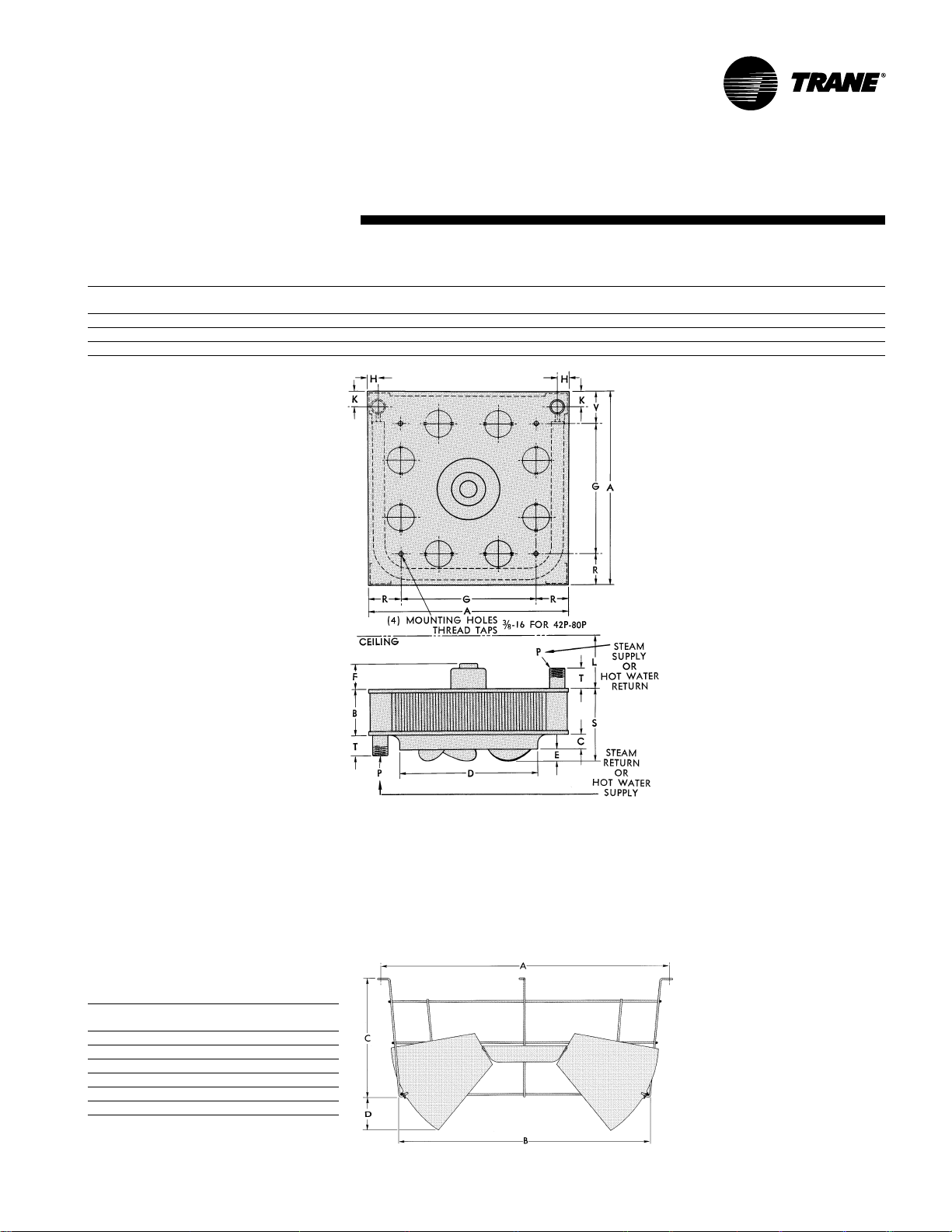
Dimensions
and Weights
Table DW-3 - Model P Unit Heater Roughing In Dimensions (Figur e D W-3)*
Unit Fan LP
Size Dia. A B C D E F G H K (Min.) (NPT) R S T U V
42 1 11/4 181/4 45/8 11/4 113/43/4 411 13/8 17/8 71
64 131/2 211/4 45/8 15/8 14 1 4 14 13/8 17/8 71
80 131/2 211/4 61/8 15/8 14 1 3 14 13/8 17/8 71
1
/2 35/8 65/8 23/4 11 35/8
1
/2 35/8 71/8 23/4 14 35/8
1
/2 35/8 85/8 23/4 14 35/8
Table DW-4 - Louver Cone Dif fuser Roughing
In Dimensions (Figure DW-4)*
Unit Size A B C D Louvers
42 161/2 141/4 61/2 25/8 8
64 & 80 20 17 8 31/8 8
102 & 122 241/4 21 93/4 315/16 8
146, 166 & 202 283/8 243/4 111/2 45/8 8
252, 280, 336 & 384
500, 600 & 720 411/2 371/4 17 43/4 12
*Note:
All dimensions approximate in inches for roughing-in
purposes. Detailed certified drawings available on request.
351/2 311/2 133/4 412
No. of
Figure D W -3
Figure DW-4
49UH-PRC001-EN
Page 50

Mec hanical Specifications
Model P
General
The “NRTLC/C” indicator adjacent to the
CSA mark signifies that the product has
been evaluated to the applicable ANSI/
UL and CSA Standards, for use in the
U.S. and Canada.
NRTL, i.e. Nationally Recognized Testing
Laboratory, is a designation granted by
the U.S. Occupational Safety and Health
Administration to laboratories which
have been recognized to perform
certification to U.S. Standards.
Casing
Formed by two square steel plates.
Bottom plate forms orifice for air
delivery. Air por ts stamped in top plate
as standard for easy removal for low
final air temperature.
Fan
T rane high ef ficiency Model A fan with
aluminum blades is quiet, factory
balanced and sturdy for standard or
spark-proof applications.
Model S
General
The “NRTLC/C” indicator adjacent to the
CSA mark signifies that the product has
been evaluated to the applicable ANSI/
UL and CSA Standards, for use in the
U.S. and Canada.
NRTL, i.e. Nationally Recognized Testing
Laboratory, is a designation granted by
the U.S. Occupational Safety and Health
Administration to labortories which have
been recognized to perform certification
to U.S. Standards.
Casing
T wo-piece with “picture frame” front
formed into wraparound sides, top and
bottom. Adjustable horizontal louvers
are standard. 18 gauge bac k panel with
deep-draw fan orifice for extreme
rigidity. Steel supply and return pipe tap
connectors bolted to back. Casings
phosphatized to prevent corrosion and
painted with blue gray baked enamel.
Fan
T rane designed and built high ef ficiency
Model A fan with aluminum blades is
quiet, factory balanced and sturdy for
standard or sparkproof applications.
Coils
Hot water-steam coils are rectangular
3 or 4-sided, one-pass, multiple circuit,
with aluminum Sigma-Flo
mechanically bonded to tubes. Standard
coils are seamless copper tubing. Coils
tested at 375 psi under water. Supply
and return connections are steel pipe.
Standard coils have .025 copper tubing
suitable for use on steam pressure to 75
psi or hot water up to 225 psi or 325 F.
When Specified) Heavy .049 red brass
tubing suitable for 75 psi steam or up to
425 deg. F water at 300 psi – .049 cupro-
nickel tubing suitable for 75 psi steam or
up to 450 deg. F water at 400 psi – .049
steel tubing suitable for 450 deg. F water
at 400 psi.
Motors
Standard motors are 1 1 5/60/1, totally
enclosed, with thermal overload
protection for all units through size 280P.
Standard motors for 42P, 64P and 80P
are shaded pole, sleeve bearing. The
102P motor is permanent split capacitor
Coils
Hot water -steam headerless coils are
single tube, single serpentine on all sizes
except 230 thru 354 which have two
circuits. Fins are aluminum
Sigma-Flo, mechanically bonded to
seamless copper tubing. All coils
one-row deep in air flow direction.
Coils tested at 400 psi air under water.
Standard coils have .031 copper tubing
suitable for use on steam pressures to 75
psi or hot water up to 200 psi or
325 F.
(When Specified) Heavy .049 red brass
tubing suitable for 75 psi steam or 390
deg. F water at 260 psi — .031 cupronickel tubing suitable for 450 deg. F
water at 400 psi — .049 steel tubing
suitable for 450 deg. F water at 400 psi.
(When Specified) Coils with turbulators
(Suffix W) available for high performance
on hot water.
(When Specified) Coils with fin series
132 (Suffix 2) for high performance on
hot water or steam.
(When Specified) Bypass Model S units
with modified coils for air bypass. Unit
®
fins
type with sleeve bearings. Motor for unit
sizes 122P through 280P are permanent
split capacitor types with permanently
lubricated ball bearings. Motors used on
unit sizes 336P through 720P are 230/460/
60/3, totally enclosed, with permanently
lubricated ball bearings. Unit sizes
smaller than 336P are also available with
230/400/60/3 motors.
All motors fractional hp and integral hp,
have Class “B” insulation. The (115/60/1
motors used as standard on unit sizes
42P through 102P can be operated at
multiple speeds with the addition of a
solid-state control.
All units available with explosion-proof
motors. Only sizes 42P, 64P, 102P and
146P are available from stoc k with
115/60/1 explosion-proof motors.
Louver Cone Diffuser
(When Specified) Available for complete
versatility in air diffusion patterns.
Adjustable 18-gauge steel blades held in
set position by spring steel clips.
sizes have odd numbers (19, 77, 243,
etc.).
Motors
Totally enclosed, 11 5/60/1 Class “B”
insulated shaded pole and PSC motors
are STD.
bearing,
bearing. All single phase motors have
built in overload protection. Sleeve
bearing motors can be oiled. Ball
bearing motors are permanently
lubricated.
The 115/60/1 motors used as standard on
unit sizes 18S through 1 00S can be
operated at multiple speeds with the
addition of a solid- state control.
All units available with explosion-proof
motors. Only sizes 18S, 42S, 90S and
126S are available from stock with
115/60/1 explosion-proof motors.
Louver Fin Diffuser
(When Specified) For versatility in lateral
diffusion, used with standard louvers,
provides four -direction control. Ships
separately and clips onto horizontal
louvers.
1
/50 through 1/8 hp are sleeve
1
/6 through 3/4 hp are ball
UH-PRC001-EN50
Page 51

Page 52

NRTL/C
The T rane Company
Unitary Products Group
2701 Wilma Rudolph Blvd.
Clarksville, TN 37040
www.trane.com
An American Standard Company
Literature Order Number
File Number
Supersedes
Stocking Location
The Trane Company has a policy of continuous product and product data impro vement, it reserves the right
to change product design and specifications without notice.
UH-PRC001-EN
PL-UN-UH-000-PRC001-10-99
UH-DS-1 8/96
Inland - LaCrosse
 Loading...