

Page 1
UCM-CLD
Chiller Control System
Owner
Manual
RLC-SVU02F-E4
Page 2

© 2009 Trane
General information
RLC-SVU02F-E4
Foreword
These instructions are given as a
guide to the operation of the
controller(s) mounted on Trane
RTAD/RTWB/RTRA chillers. They do
not contain full service procedures
necessary for the continued
successful operation of this
equipment. The services of a qualified
technician should be employed
through the medium of a
maintenance contract with a
reputable service company. Read
this manual thoroughly before unit
start-up.
Warnings and cautions
Warnings and Cautions appear at
appropriate sections throughout this
manual. Your personal safety and the
proper operation of this machine
require that you follow them
carefully. The constructor assumes no
liability for installations or servicing
performed by unqualified personnel.
WARNING! : Indicates a potentially
hazardous situation which, if not
avoided, could result in death or
serious injury.
CAUTION! : Indicates a potentially
hazardous situation which, if not
avoided, may result in minor or
moderate injury. It may also be
used to alert against unsafe
practices or for equipment or
property-damage-only accidents.
Safety recommendations
To avoid death, injury, equipment or
property damage, the following
recommendations should be
observed during maintenance and
service visits:
1. The maximum allowable pressures
for system leak testing on low and
high pressure side are given in the
chapter "Installation". Always provide
a pressure regulator.
2. Disconnect the main power supply
before any servicing on the unit.
3. Service work on the refrigeration
system and the electrical system
should be carried out only by
qualified and experienced personnel.
Reception
On arrival, inspect the unit before
signing the delivery note.
Reception in France only:
In case of visible damage: The
consignee (or the site representative)
must specify any damage on the
delivery note, legibly sign and date
the delivery note, and the truck driver
must countersign it. The consignee
(or the site representative) must
notify Trane Epinal Operations Claims team and send a copy of the
delivery note. The customer (or the
site representative) should send a
registered letter to the last carrier
within 3 days of delivery.
Note: for deliveries in France, even
concealed damage must be looked
for at deli
very and immediately
treated as visible damage.
Reception in all countries except
France:
In case of concealed damage: The
consignee (or the site representative)
must send a registered letter to the
last carrier within 7 days of delivery,
claiming for the described damage.
A copy of this letter must be sent to
Trane Epinal Operations - Claims
team.
Warranty
Warranty is based on the general
terms and conditions of the
manufacturer. The warranty is void if
the equipment is repaired or
modified without the written
approval of the manufacturer, if the
operating limits are exceeded or if
the control system or the electrical
wiring is modified. Damage due to
misuse, lack of maintenance or
failure to comply with the
manufacturer's instructions or
recommendations is not covered by
the warranty obligation. If the user
does not conform to the rules of this
manual, it may entail cancellation of
warranty and liabilities by the
manufacturer.
Maintenance contract
It is strongly recommended that you
sign a maintenance contract with
your local Service Agency. This
contract provides regular
maintenance of your installation by a
specialist in our equipment. Regular
maintenance ensures that any
malfunction is detected and corrected
in good time and minimizes the
possibility that serious damage will
occur. Finally, regular maintenance
ensures the maximum operating life
of your equipment. We would remind
you that failure to respect these
installation and maintenance
instructions may result in immediate
cancellation of the warranty.
Training
To assist you in obtaining the best
use of it and maintaining it in perfect
operating condition over a long
period of time, the manufacturer has
at your disposal a refrigeration and
air conditioning service school. The
principal aim of this is to give
operators and technicians a better
knowledge of the equipment they are
using, or that is under their charge.
Emphasis is particularly given to the
importance of periodic checks on the
unit operating parameters as well as
on preventive maintenance, which
reduces the cost of owning the unit
by avoiding serious and costly
breakdown.
Page 3

Contents
3RLC-SVU02F-E4
General Information 2
Principles of operation
of the UCM-CLD module 4
General Information 4
Operator’s Interface 5
Operational Features 9
Diagnostics 16
Diagnostics 16
Default Description 17
Controller for hydraulic module/
free cooling / heat recovery / RTWB
heat pump applications 22
Hydraulic module control 23
Control logic 23
Module and outputs/inputs 24
Hydraulic module option 25
Data display menu 26
Configuration menu 27
Alarms messages - hydraulic module application 30
Mask and menu chart 31
Free cooling application 32
Heat recovery application 38
RTWB heat pump application 40
Page 4
Principles of Operation of the
Module UCM-CLD
RLC-SVU02F-E44
General Information
This UCM-CLD chiller control is
composed of eight electronic
modules, which each have their
own 115V or 24V power supply and
communicate with each other via a
serial link. The names of the
modules are linked to their
functions.
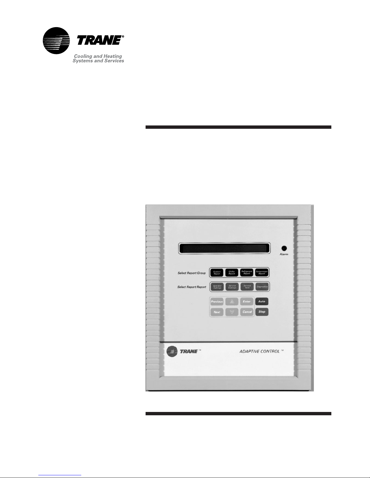
Figure 1 : Operator’s interface
Compressor
Report
Refrigerant
Report
Chiller
Report
Custom
Report
Select Report Group
Diagnostics
Service
Tests
Service
Settings
Operator
Settings
Alarm
AutoEnterPrevious
StopCancelNext
Select Setting Group
ADAPTIVE CONTROL™
Module Functions
MCSP (Motor Compressor Start and Protection)
CPM (Chiller Protection and Management) Safety, protection, and control of the chiller
EXV (Electronic Expansion Valves) Control of both electronic expansion valves
CSR (Communication and Setpoint Reset) ,
Local CLD (Local Clear Language Display) Operator interface located in the front panel of the unit
Remote CLD (Remote Clear Language Display)
TCI IV, COM 3 (Tracer Communication Interface 4, COM 3)
Safety, protection, and control of the helical-rotary compressor and
its components
Control of the serial communication, unit external setpoints and
ice-making mode (optional module)
Operator interface located up to 1500m from the unit, able to
communicate with up to four units of the same type (optional module)
TCI IV, IPCB (Tracer Communication Interface 4, Inter Processor
Communication Buffer)
Protection of the internal communication bus in the unit from external
interferences (optional factory-mounted module, compulsory when
using a Remote CLD)
Interface between the control of the unit and a Building Management
System using Trane COMM 3 serial link
Page 5
Principles of Operation of the
Module UCM-CLD
5RLC-SVU02F-E4
Operator's Interface
Digital Display
The display of control regulation and
operating parameters, diagnostics,
and error messages is a 2-line, 40character, liquid-crystal display. The
display has a LED backlight to read
in low-light conditions and to warm
up the display under low ambient
temperatures. When powering up
the system, the display is not lit and
the message [SELF-TEST IN
PROGRESS] is displayed. The screen
can display error codes, settings of
various setpoints, specified
temperature and pressure values,
and the status of operating
parameters and options.
Keyboard
A 16-key touchpad allows both
navigation between menus and the
modification of parameters and
setpoints. The keys are divided into
two groups:
Individual Menu Keys Control Keys
Chiller Report Menu + key
Custom Report Menu
- key
Refrigerant Menu Previous key
Compressor Menu Next key
Operator Settings Menu Enter key
Service Settings Menu* Cancel key
Service Test Menu* Auto key
Diagnostics Menu Stop key
* Levels 2 and 3 of the Service Settings Menu and the Service Test Menu are protected by a
password and are reserved for Trane Service Engineers.
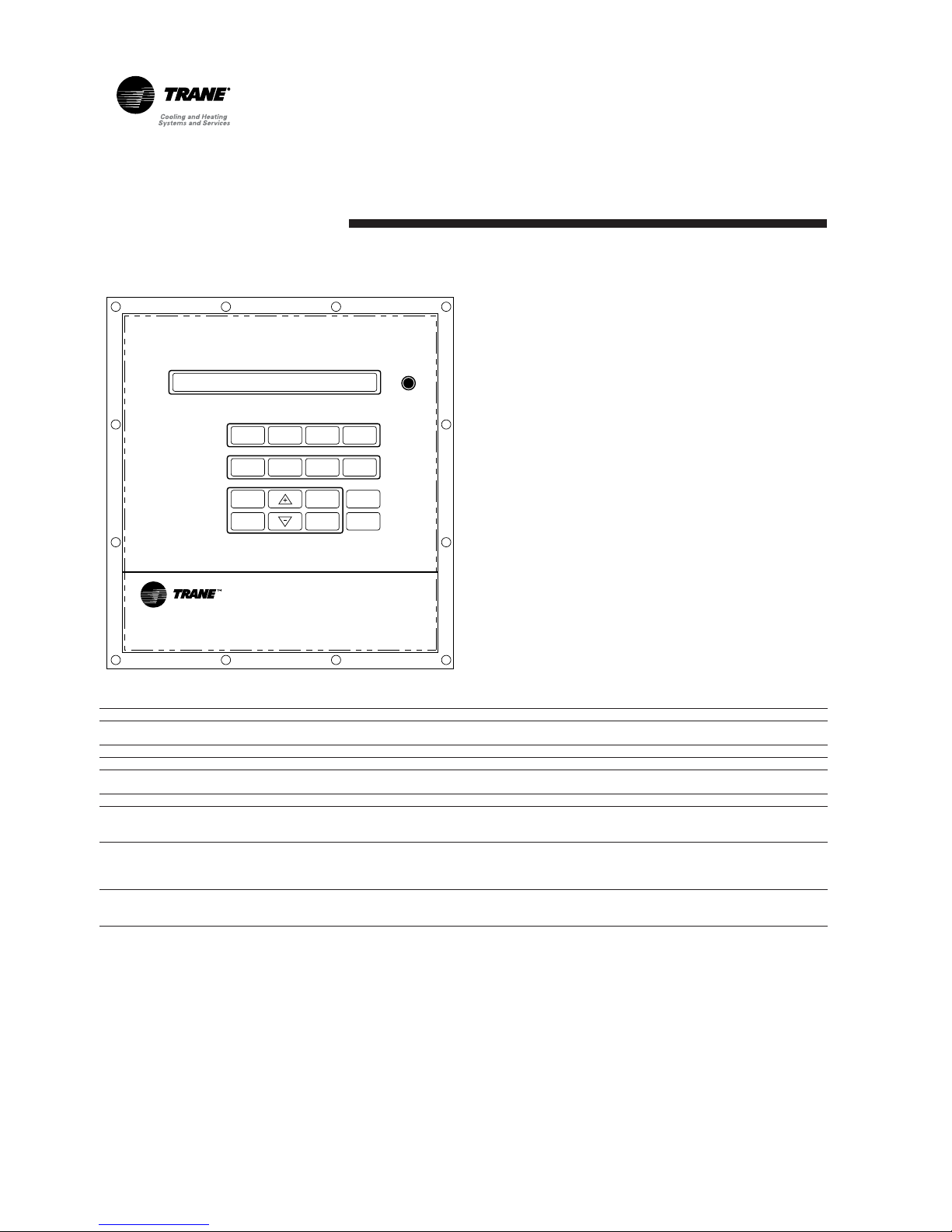
Figure 2 : Control panel mounted on a model RTWA unit
Page 6

Principles of Operation of the
Module UCM-CLD
RLC-SVU02F-E46
Control Key Functions
[+] key If the information displayed
is read-only, pressing this key will
add it to the operator's menu. If the
information can be modified,
pressing this key will increase the
value without exceeding the
maximum possible value.
[-] key If the information displayed
is read-only, pressing this key will
remove it from the operator's menu.
If the information can be modified,
pressing this key will decrease the
value without exceeding the
minimum possible value.
[Previous] key Pressing this key
allows the operator to scroll up to
the previous information in the
current menu. Each menu is
looped, making it possible to scroll
from the first item in the menu to
the last item.
[Next] key Pressing this key allows
the operator to scroll down to the
next information in the current
menu. Each menu is looped, making
it possible to scroll from the last item
in the menu to the first item.
[Enter] key Pressing this key allows
the operator to validate a value after
modification.
[Cancel] keyThis key should be
pressed if a modified setting should
not be saved.
[Auto key] Pressing this key allows
the unit to be in Auto mode if it was
previously placed in Stop mode
with the [Stop] key. The unit cannot
be forced into Auto mode if an
external contact or the serial link
has stopped it. When the unit is
stopped by the remote interface
(Remote CLD), the local mode order
has priority.
[Stop] key Pressing this key allows
the unit to be in Stop mode. In
every case, and whatever the origin
(except a local stop), the stop order
and stop status have priority over a
run order. The stop generated is a
soft stop - the unit unloads before
stopping.
Whether a [Stop] or [Auto]
command will be accepted and
stored is based on the following
hierarchy:
1. Local Stop will always replace
Local Auto, Remote Auto, and
Remote Stop.
2. Local Auto will always replace
Local Stop, Remote Auto, and
Remote Stop.
3. Remote Stop will always replace
Local Auto and Remote Auto. It
will not replace Local Stop.
4. Remote Auto will always replace
Local Auto and Remote Stop. It
will not replace Local Stop.
Pressing the [Stop] key twice within
five seconds will result in an
Emergency Stop. The chiller will not
unload.
Page 7
Principles of Operation of
the Module UCM-CLD
7RLC-SVU02F-E4
Parameters and setpoints within each menu
Menu Parameters/setpoints Range
Minimum/Maximum
Chiller Report Menu Active Chilled Water Setpoint
Evaporator Entering/ Leaving Chilled Water Temperature
Condenser Entering / Leaving Chilled Water Temperature
Active Ice-Storing Setpoint
Active Hot Water Setpoint
Entering/Leaving Hot Water Temperature
Current Active Setpoint limits -17.8°/18.3°C
Evaporator/Condenser Waterflow
Ambient Air Temperature
Sources of setpoints (Tracer, local CLD, external)
Custom Report Menu Custom-built by the operator (Can contain up to 20 settings)
Refrigerant Report Menu Condenser/Evaporator Refrigerant Pressures
Refrigerant Temperature in Condenser
Refrigerant Temperature in Evaporator
Compressor Report Menu Compressor Status
Time and Start Counters
Amps (% RLA)
Oil Temperature (GP compressor only)
Operator Settings Menu Setpoint Source
External Chilled Water Setpoint
External Hot Water Setpoint
Chilled Water Pump Operation
Chilled Water Pump Off Delay 1 min/30 min
Ice Machine Control*
Panel Ice Termination Setpoint -6.6°/-0.5°C
Low Ambient Lockout
Low Ambient Lockout Setpoint -28.8°/15.5°C
Front Panel Current Limit Setpoint 40%/120%
Front Panel Hot Water Setpoint 25°/60°C
Front Panel Chilled Water Setpoint -17.8°/18.3°C
Design Delta Temperature Setpoint 2.2°/16.6°C
External Current Limit Setpoint
Differential to Start Setpoint 1.1°/16.6°C
Chilled Water Reset Type
Type Reset Ratio
Type Start Reset Setpoint
Type Max Reset Setpoint 0.0°/11.1°C
Page 8
Principles of Operation of
the Module UCM-CLD
RLC-SVU02F-E48
Service Settings Menu** LEVEL ONE-Information adjusted by customer
Unit Line Voltage
Over/Undervoltage Protection
Restart Inhibit Time 30/120 sec
Balanced Compressor Starts and Hours
Display Language and Units
Programmable Relay Set-up 1/12
External Circuit Lockout
LEVEL TWO- Information adjusted by Service Engineer
Address of Serial Link 0/64
Display Lock Feature
Leaving Water Temperature Setpoint
Low Refrigerant Temperature Cutout Setpoint
Low Water Temperature EXV Air Compressor
Condenser Limit Setpoint 60/120%
Phase Unbalance Protection
Phase Reversal Protection
Superheat Setpoint 2.2°/11.1°C
EXV Control Response Circuit 1 2/200
EXV Control Response Circuit 2 2/200
Leaving Water Temperature Control Response Setpoint
Fan Control Deadband bias Circuit 1 -50/50
Fan Control Deadband bias Circuit 2 -50/50
LEVEL THREE-Configuration/Protection Information
Compressor Model Number Prefix
Number of Compressors
Oil Loss Differential Setpoint
Compressor A Ton
Compressor B Ton
Compressor C Ton
Compressor D Ton
Fan Control
Variable Speed Fan Circuit 1
Variable Speed Fan Circuit 2
Number of Fans Circuit 1
Number of Fans Circuit 2
Reduced Inrush Starting
Current Overload Compressor A
Current Overload Compressor B
Current Overload Compressor C
Current Overload Compressor D
Low Ambient Unit Half Air Flow Fan
Low Ambient Unit Two-Speed Motor
Night Noise Setback
Number of EXV Circuit 1
Number of EXV Circuit 2
Refrigerant Type
Service Tests Menu Perform Expansion Valve Test
Perform Circuit locking or Pump-out Test
Perform Compressor Test
Diagnostics Menu Current Diagnostics
History of Diagnostics
Manual Reset of Diagnostics
Erase History of Diagnostics
* Option
** This menu has three access levels. The control has a display lock feature that can be locked at request after level one.
Page 9

Principles of Operation of
the Module UCM-CLD
9RLC-SVU02F-E4
Operational features
Entering evaporator water
temperature
When one or both compressors are
running, the UCM continually
monitors and compares the
entering and leaving evaporatorwater temperatures. If the
temperature of the entering water
drops more than 1°C below the
leaving water temperature for more
than
55°C- seconds, the UCM uses this to
indicate a loss of water flow
through the evaporator. This will
shut down that circuit's compressor
and will display MMR diagnostic.
Current Limit Setpoint (CLS)
The current limit setpoints for the
system are entered through the
Clear Language Display menus. The
current limit Setpoint for each
compressor is shown in Table 1.
Table 1 – Compressor current limit
Setpoint versus Chiller current
limit Setpoint
System
CLS One Two
120% 120 120
100 % 120 100
80% 120 80
60% 120 60
40% 80 40
Based upon current levels received
at the UCM, the compressor slide
valve is modulated to prevent the
actual chiller current from
exceeding the CLS.
When a compressor is turned off,
the CLS for the remaining running
compressor shall be reset upward
immediately. When a compressor is
added, the CLS for the running
compressor shall be ramped
downward at a rate not less than
10% RLA per minute to the new
Setpoint.
Numbers of compressor in
operation
Electronic expansion valve
(EXV) test
This test can be performed only when
the “Stop“ key has been pressed. It
will confirm proper operation of the
electronic expansion valve and the
EXV module.
After the test has been initiated at
the Clear Language Display, the
UCM will:
1. Overdrive the EXV closed
(25 seconds)
2. Overdrive the EXV open
(25 seconds)
3. Overdrive the EXV closed
(25 seconds)
4. Reset the display to disable and
end the test
The EXV produces an audible
clicking sound when it is driven
against its end stops. Step 1 drives
the EXV to its closed position,
during which time service personnel
can move from the CLD to the EXV.
Note: A tool may be needed to aid
in hearing the clicking of the EXV,
such as a screwdriver held between
the EXV and the ear.
Current overload protection
The UCM continually monitors
compressor current to provide unit
protection in the event of an
overcurrent or locked-rotor
condition. Protection is based on
the phase with the highest current
and, if limits are exceeded, the UCM
will shut down the compressor and
will display an MMR diagnostic.
Leaving chilled-water temperature
control
If the Auto key is pressed and a
remote chilled-water Setpoint has
been communicated, the UCM will
control to that Setpoint. Otherwise,
it will control to the front-panel
Setpoint. Control is accomplished
both by staging compressors and
by modulating the slide valves on
each compressor.
Upon start-up, if the leaving chilledwater temperature is dropping 0.8°C
per minute or faster, the chiller will
not load further.
Page 10

Principles of Operation of
the Module UCM-CLD
RLC-SVU02F-E410
Chilled-Water Reset (CWR)
As an option, the UCM will reset the
chilled-water temperature setpoint,
based on either the return water
temperature or the outdoor air
temperature. The CSR module is
necessary to perform CWR.
The following are selectable:
One of four reset types, from top to
bottom in order of reset:
no CWR
RETURN WATER TEMPERATURE
RESET
ZONE TEMPERATURE RESET
OUTDOOR AIR TEMPERATURE
RESET
Leaving-water temperature cutout
This temperature cutout provides
protection against freezing caused
by low leaving-water temperature.
The setpoint is both factory-set and
adjustable from the Service Setting
Menu. Temperatures below the
setpoint will cause the UCM to
accelerate reduction of chiller
capacity, even to the point of
compressor shutdown. A nonlatching diagnostic will be
generated if the LWT is below the
cutout for more than 16°C-seconds.
There must be a minimum of 2.7°C
between the cutout temperature
and both the front-panel and activechilled-water setpoints. The Clear
Language Display will not permit
setting of either the front-panel or
active-chilled-water temperatures
less than 2.7°C above the cutout
temperature. The second line will
state:
Limited by Cutout Setpoint (+)
to change
If the leaving-water temperature
cutout is set upward, the Clear
Language Display will maintain the
2.7°C minimum and will
automatically raise the settings on
the front-panel and active-chilledwater setpoints, if necessary.
If the front-panel or active-chilledwater setpoints were adjusted, the
display will show the following
when the “enter“ key is pressed:
FRONT PANEL CHILLED WATER
SETPOINT HAS BEEN
INCREMENTED DUE TO CUTOUT
SETPOINT CHANGE
If the leaving-water temperature
drops below the cutout setpoint
while the compressors are deenergized, it will produce an IFW
diagnostic. If the leaving-water
temperature drops below the cutout
setpoint while the compressors are
energized for 16°C-seconds, the unit
will shut down on an MAR
diagnostic.
Page 11
Principles of Operation of
the Module UCM-CLD
11RLC-SVU02F-E4
Low refrigerant temperature cutout
Both circuits are protected from a
saturated-evaporator refrigerant
temperature that goes below this
setting. The cutout Setpoint must be
at a minimum of 8°C lower than the
front panel or active chilled-water
setpoints. See Table 2 for proper
settings.
There must be a minimum of 8°C
between the cutout temperature
and active chilled-water setpoints.
The Clear Language Display will not
permit setting of the chilled-water
temperature less than 8°C above
this cutout temperature, and the
display will flash the last valid
temperature.
If the leaving-water temperature
cutout is set upward, the Clear
Language Display will maintain the
8°C minimum and will raise the
settings of the chilled-water
setpoints, if necessary.
If the chilled-water setpoints were
adjusted, the display will show the
following when the “Enter“ key is
pressed:
FRONT PANEL CHILLED WATER
SETPOINT HAS BEEN
INCREMENTED DUE TO CUTOUT
SETPOINT CHANGE
If the saturated-evaporator
refrigerant temperature for a circuit
drops below this Setpoint for longer
than 16°C-seconds, the circuit will
be shut down and a CMR diagnostic
will be displayed.
Table 2 – Leaving fluid temperature setpoints
°C °C °C % °C
5 1.5 -3.9 0 0
4 1 -4.4 10 -4
3 0 -5.4 13 -5
2-1 -6.416-7
1-2 -7.418-8
0-3 -8.420-9
-1 -4 -9.4 22 -10
-2 -5 -10.4 24 -11
-3 -6 -11.4 26 -13
-4 -7 -12.4 27 -13
-5 -8 -13.4 29 -15
-6 -9 -14.4 31 -16
-7 -10 -15.4 32 -17
-8 -11 -16.4 33 -18
-9 -12 -17.4 34 -19
-10 -13 -18.4 36 -20
-11 -14 -19.4 36 -20
-12 -15 -20.4 37 -21
Leaving
chilled-water
temperature
Leaving-water
temperature
cutout
Low refrigerant
temperature
cutout
Recommended
%EG
Solution
freeze
point
Page 12
Principles of Operation of
the Module UCM-CLD
RLC-SVU02F-E412
Balanced compressor starts
and hours
This feature is enabled/disabled in
balanced starts and hours (service
setting menu). When enabled, the
UCM will start the compressor with
the fewest starts and stop the
compressor with the greatest number
of operating hours, as determined by
the “compressor starts“ accumulator
and the “compressor hours“
accumulator. This will tend to balance
out hours and starts equally over both
compressors.
Phase imbalance protection
The Clear Language Display
monitors the current in each phase
and calculates the percentage of
imbalance as follows:
% imbalance = (Ix - I average)
I average
I average = (I1 + I2 + I3) / 3
Ix = phase with greatest difference
from I average (without regard
to sign).
If phase-unbalanced protection
(service setting menu) is enabled
and the average three-phase current
is greater than 80% RLA, and the
percent of imbalance is calculated
to exceed 15%, the UCM will shut
down the compressor and display a
CMR diagnostic.
Reverse rotation protection
The Clear Language Display
monitors incoming current during
start-up and will shut down the
compressor within one second if
phase reversal is detected.
CCAAUUTTIIOONN
Phase relationship during
installation of unit power must be
carefully controlled to ensure
compressor protection against
reversed rotation.
Oil failure protection
The logic of the UCM uses a
comparison of the entering oil
temperature at the compressor, to
the saturated-condenser
temperature, to determine if there is
an oil line restriction.
The differential between the
entering-oil and the saturatedcondenser temperatures is referred
to as the “oil loss differential
setpoint“ in the service settings
menu.
If the entering oil temperature drops
2°C below the saturated-condenser
temperature for more than
30 minutes, the circuit will shut
down on a CMR diagnostic. The
diagnostic will be presented as:
OIL SYSTEM FAULT - CKT X
DIP switch settings
Compressor overload DIP switches.
IPC address
The IPC address sets the address for Inter-Processor Communications of the
Clear Language Display modules. The following are the IPC DIP switch
settings for the modules.
Module
IPC DIP A20-1 A20-2 A52 A9
Switch SW1 SW2 SW1 SW2 SW1 SW1
1 OFF Based OFF Based OFF OFF
2 OFF On OFF On OFF OFF
3 Motor Motor
4 RLA RLA
5
Page 13
Principles of Operation of
the Module UCM-CLD
13RLC-SVU02F-E4
2-10 V (dc)/4-20 mA input for External
Chilled-Water Setpoint (CWS) or
Current limit Setpoint (CLS)
When either external CWS or
external CLS is used on the optional
module A9, DIP switch SW1
positions 1 and/or 2 must be set to
accommodate the type of of signal
source the customer has chosen,
either 2-10 V (dc) or 4-20 mA.
Position SW1-1 sets 2-10 V (dc)/420 mA for external CLS. The “OFF“
setting configures the external input
for 2-10 V (dc)/4-20 mA for external
CLS. The “OFF“ setting configures
the external input for 2-10V (dc), the
“ON“ setting configures the
external input for 4-20 mA.
Leaving Condenser-Water
Temperature control option Model RTWB
If the machine is delivered with the
LCWT control option (digit 49
position 3), the DIP switch on the
module A9 must be set at position
“ON.“ This option controls the
condenser (CDS) leaving-water
temperature (LCWT) based on a Hot
Water Temperature setpoint (HWSP).
Mechanical control settings
The settings for the High Pressure switch are shown below:
Pressure Switch Approval Close Open
B51 PED 19-20 bar 22-23 bar
High Pressure Czech republic
Poland
B23 PED 1.5 bar 0.5 bar
Low Pressure Czech republic
Poland
-4°C<LWTE<+15°C
B23 PED 1.2 bar 0.2 bar
Low Pressure Czech republic
Poland
-12°C<LWTE<-4°C
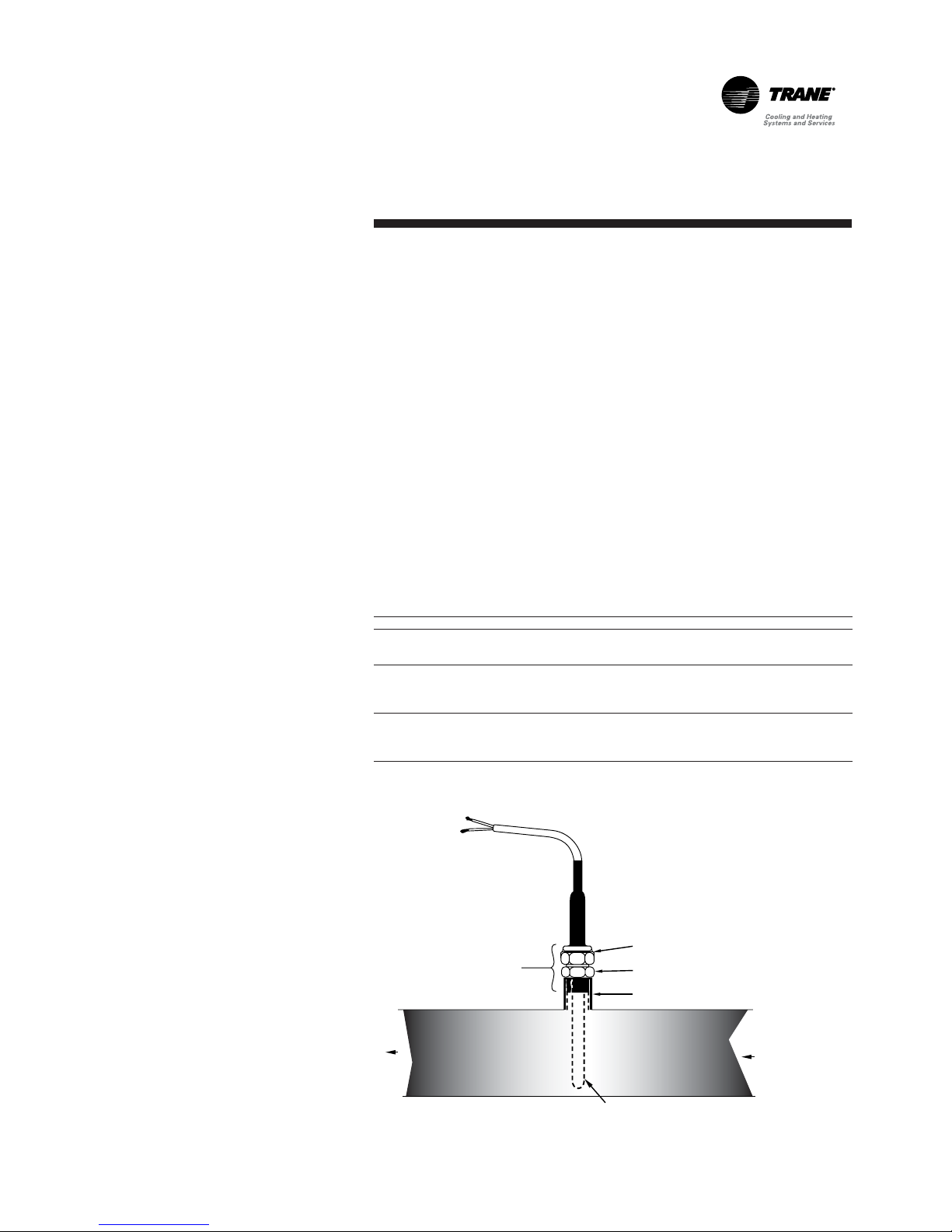
Figure 3 - Water Temperature Sensor Installation - Model RTWB
Compression
Fitting
Clamping Nut
Fitting Body
1/2" NPT x 1-1/2" Large Coupling
Limitations
In the heating mode, the chiller is
not able to provide chilled water for
a process. The leaving chilled-water
temperature is not controlled. The
UCM will only take care of safeties
(water flow and freezing).
The option will provide contact to
start/stop the evaporator and the
condenser pumps. Any other devices
such as valves (2 ways/3 ways), heat
exchangers, variable-volume pumps,
or other equipment will have to be
controlled by another system.
Condenser Water Temperature
Sensors - RTAD Total and Partial
Heat Recovery
UCM-CLD will not display leaving
and entering water temperature
above 70.1°C, whereas on Total Heat
Recovery units, the temperature on
the additional controller could be
higher. These conditions would
appear in cooling mode only. This is
not harmful to the operation of the
chiller.
Page 14

Principles of Operation of
the Module UCM-CLD
RLC-SVU02F-E414
Hot-Water Mode Control
Module - Option Model
RTWB
Scope of Supply
The following parts will be installed
in the control panel of the unit:
• One Additional Board A70 with
display
• One CDS LWT sensor + immersion
well to be installed by the customer
The sensor will be connected to
terminals B3 and GND on terminal
block J2 of the A70 module.
Sequence of Operation
• Cooling Mode
The unit will operate as a standard
chiller (i.e., the chiller controls the
leaving chilled-water temperature).
The condenser pump will be driven
by the UCM relay. The chiller uses
the cooling setpoint defined in the
A70 Module.
• Heating Mode
In the heating mode, the chiller will
control the condenser leaving-water
temperature. The temperature sensor
connected to the A70 Module should
be located in the condenser leavingwater connection downstream from
the condenser. The control is done by
loading or unloading the chiller. To
load or unload the chiller, a chilledwater setpoint reset is applied (i.e.,
setpoint decrease = load; setpoint
increase = unload). The condenser
pump is always in operation. The
evaporator pump is still controlled by
the UCM and is always in operation.
The chiller uses the heating setpoint
defined in the A70 Module.
The chiller will be stopped if the
condenser leaving-water
temperature is greater than the
setpoint + the “differential to stop”.
The chiller will start if the condenser
leaving-water temperature is lower
than the setpoint - the “differential
to start”.
• Sensor Failure
In the heating mode, and if the CDS
leaving-water temperature sensor
fails, the chiller is stopped and the
alarm relay of the A70 Module is
energized. The chiller can operate in
the cooling mode if the CDS
leaving-water temperature sensor
has failed.
A70 Module and UCM interaction
Chilled-Water setpoint: The A70
Module drives the chilled-water
setpoint using a linear signal from
an Analog Output of the A70
Module to the external chilled-water
setpoint input of the UCM.
Chiller Enable/Disable: The A70
Module drives the chiller (on or off)
using a dry contact from the A70
Module to the external start/stop
input of the UCM.
CDS pump relay: The A70 Module
drives the condenser pump relay.
In heating mode, the chiller controls
the condenser leaving-water
temperature. The A70 Heat Pump
Module sends an external chilledwater setpoint to the UCM. This
analog signal (factory set at 420mA) is constantly reset to match
the heating load.
• Setpoint decreases Æ load the
chiller
• Setpoint increases Æ unload the
chiller
Note that the UCM still operates as
a chilled-water controller.
On the UCM-CLD, the parameter
“External Chilled Water setpoint”
has to be enabled.
Page 15

Principles of Operation of
the Module UCM-CLD
15RLC-SVU02F-E4
Local/ External unit control mode
From the Settings menu, the end
user can select the Control mode.
- Control Mode: No
In this case, the active cool and heat
setpoints and Heat/Cool selection
will come from the front panel (User
Settings 1).
- Control Mode: Partial
In this case, the active cool and heat
setpoints will come from the front
panel (User Settings 1). The active
Heat/Cool selection will come from
the external Cool/Heat input.
- Control Mode: Full
In this case, the active cool and heat
setpoints and Heat/Cool selection
will come from the external analog
and digital inputs.
- AI: External cooling setpoint input
(configurable)
This input will be powered in 0-1V
or 4..20mA. The configuration
(available from menu “User
Settings 2) will allowed 0-1V or
4..20mA signals. This signal will
create a cooling setpoint between
-17.8°C and 18.3°C.
Note: The A70 module will scale
automatically the value between
-12°C and 15°C.
Note: The input configuration must
be done before any signal
connection.
Refer to Table 4 for the setting rule.
- AI: External heating setpoint input
(configurable)
This input will be powered in 0-1V
or 4..20mA. The configuration will
allowed 0-1V or 4..20mA signals.
This signal will create a heating
setpoint between 25°C and 60°C.
Note: The input configuration must
be done before any signal
connection.
Refer to Table 3 for the setting rule.
- DI: External ON/OFF input
This input will be normally powered
in 24Vac. This input will be the
external Auto/Off unit.
0V "Open" : unit disabled
24Vac "Close" : unit enabled
- DI: External Heat/Cool input
(configurable)
This input will be normally powered
in 24Vac. This input will be the
external Heat/Cool mode switch.
0V "Open" : Cooling mode
24Vac "Close" : Heating mode
Table 4 - Input values vs. External chilled-water setpoint
3.6 7.2 -10
4.6 9.2 -5
5.6 11.3 0
6.7 13.3 5
7. 7 1 5 . 4 10
Resulting hot-water
set point
(°C)
Voltage
(V(dc))
Current
(mA)
Page 16

Diagnostics
RLC-SVU02F-E416
When a circuit shutdown - manual
reset (CMR) or a machine shutdown
- manual reset (MMR) occurs, the
red LED to the right of the display
will flash. Otherwise this alarm LED
is de-energized.
If there are no diagnostic messages,
the selected menu item will be
displayed continuously. If the
diagnostics key is pressed and there
are no active diagnostics, the
readout on the display will be:
When a system malfunction occurs,
one of the following appropriate
diagnostic messages will be
displayed:
*** Informational warning ***
An informational warning occurred
but has cleared “press (Next)”
*** A circuit shutdown has
occurred ! ***
A circuit shutdown occurred
but has cleared “press (Next)”
*** A machine shutdown has
occurred ! ***
A machine shutdown occurred
but has cleared “press (Next)”
NO ACTIVE DIAGNOSTICS
PRESENT
If more than one diagnostic is
present, only the highest priority
active diagnostic will be explained
in detail. For example, if the
diagnostics occur in the following
order before the operator returns IFW, MMR, CMR - the display will
read:
because the MMR has the highest
priority. However, as the operator
moves through the diagnostic menu
to the “Last diagnostic,” the
[Diagnostic description] will show
the CMR diagnostic as well as the
IFW. If the “Next” key is pressed,
the display will show all the other
active and historic diagnostics.
The active diagnostic priorities,
listed from highest to lowest are:
Machine shutdown - manual reset
(MMR)
Machine shutdown - automatic reset
(MAR)
Circuit shutdown - manual reset
(CMR)
Circuit shutdown - automatic reset
(CAR)
Informational warning (IFW)
*** A machine shutdown has
occurred ! ***
Page 17

Diagnostics
17RLC-SVU02F-E4
Default description
Displayed Code Type Description
Fault 87
Check External Chilled Water Setpt : IFW - Value out of range
Fault 89
Check External Current Limit Setpt : IFW - Value out of range
Fault 8A
Chilled Water Flow (Ent Wtr Temp) : MMR 1) Entering water temperature < leaving WT
2) No water flow
3) Defective EVP sensor
Fault 8E
Evaporator Entering Water Temp Sensor : MMR - Defective sensor
Fault 8F
Condenser Rfgt Temp Sensor - Ckt 1 : MMR -Defective sensor
Fault 90
Condenser Rfgt Temp Senspr - Ckt 2 : MMR - Defective sensor
Fault 93
Evaporator Rfgt Temp Sensor - Ckt 1 : MMR - Defective sensor
Fault 94
Evaporator Rfgt Temp Sensor - Ckt 2 : MMR - Defective sensor
Fault 9A
Condenser Entering Water Temp Sensor : IFW - Defective sensor
Fault 9b
Condenser Leaving Water Temp Sensor : IFW - Defective sensor
Fault A0
Zone Temp Sensor : IFW - Defective sensor
Fault A1
Outdoor Air Temp Sensor : IFW - Defective sensor
Fault Ab
Evaporator Leaving Wtr Temp Sensor : MMR - Defective sensor
Fault b5
Low Pressure Cutout - Ckt 1 : CMR - LP pressure switch open
Fault b6
Low Pressure Cutout - Ckt 2 : CMR - LP pressure switch open
Fault bA
Overload trip - Cprsr A : CMR - Current exceeded
Fault bb
Overload Trip - Cprsr B : CMR - Current exceeded
Fault bC
Overload trip - Cprsr C : CMR - Current exceeded
Fault bd
Overload trip - Cprsr D : CMR - Current exceeded
Fault bE
High Pressure Cutout - Cprsr C : CMR - HP too high
Fault bF
High Pressure Cutout - Cprsr D : CMR - HP too high
Fault C5
Low Chilled Water Temp (Unit Off) : IFW - Antifreeze protection
Fault C6
Low Chilled Water Temp (Unit On) : MAR - Antifreeze protection
Fault CA
Contactor - Cprsr A : MMR - Welded compressor contactor
Fault Cb
Contactor - Cprsr B : MMR - Welded compressor contactor
Fault CC
Contactor - Cprsr C : MMR - Welded compressor contactor
Fault Cd
Contactor - Cprsr D : MMR - Welded compressor contactor
Fault d7
Over Voltage : MAR - Voltage 10% > nominal
Fault d8
Under Voltage : MAR - Voltage 10% < nominal
Fault Ed
Chilled Water Flow Interlock : MAR - Flow switch open more than 6 sec.
Fault F5
High Pressure Cutout - Cprsr A : MMR - HP too high
Fault F6
High Pressure Cutout - Cprsr B : MMR - HP too high
Fault Fd
Emergency Stop Input : MMR - Emergency stop input open
Page 18

Diagnostics
RLC-SVU02F-E418
Default description
Displayed Code Type Description
Fault 180
Starter Transition - Cprsr A : CMR 1) Transition proof signal not received
2) Proof input shunted
Fault 181
Starter Transition - Cprsr B : CMR 1) Transition proof signal not received
2) Proof input shunted
Fault 182
Starter Transition - Cprsr C : CMR 1) Transition proof signal not received
2) Proof input shunted
Fault 183
Starter Transition - Cprsr D : CMR 1) Transition proof signal not received
2) Proof input shunted
Fault 184
Phase Reversal - Cprsr A : CMR - Phase reversed
Fault 185 :
Phase reversal - Cprsr B CMR - Phase reversed
Fault 186
Phase reversal - Cprsr C : CMR - Phase reversed
Fault 187
Phase reversal - Cprsr D : CMR - Phase reversed
Fault 190
Low Superheat - Ckt 1 : CMR - Superheat < 1°C during more than 1333°C x sec
Fault 191
Low Superheat - Ckt 2 : CMR - Superheat < 1°C during more than 1333°C x sec
Fault 194
Low Evap Rfgt Temp. - Ckt 1 : CMR
Fault 195
Low Evap Rfgt Temp. - Ckt 2 : CMR
Fault 198
Low Oil Flow - Cprsr A : CMR - Oil flow switch open during more than 20 sec
Fault 199
Low Oil Flow - Cprsr B : CMR - Oil flow switch open during more than 20 sec
Fault 19A
low Oil Flow - Cprsr C : CMR - Oil flow switch open during more than 20 sec
Fault 19b
Low Oil Flow - Cprsr D : CMR - Oil flow switch open during more than 20 sec
Fault 19C
Phase Loss - Cprsr A : CMR - Loss of 1 or more phases
Fault 19d
Phase Loss - Cprsr B : CMR - Loss of 1 or more phases
Fault 19E
Phase Loss - Cprsr C : CMR - Loss of 1 or more phases
Fault 19F
Phase Loss - Cprsr D : CMR - Loss of 1 or more phases
Fault 1A0
Power Loss - Cprsr A : CAR - Loss of all three phases in operation
Fault 1A1
Power Loss - Cprsr B : CAR - Loss of all three phases in operation
Fault 1A2
Power Loss - Cprsr C : CAR - Loss of all three phases in operation
Fault 1A3
Power Loss - Cprsr D : CAR - Loss of all three phases in operation
Fault 1A4
Tracer Communication Loss : IFW - Loss of external information
Fault 1A5
Oil Flow Control - Cprsr A : CMR - Problem on oil circuit
Fault 1A6
Oil Flow Control - Cprsr B : CMR - Problem on oil circuit
Fault 1A7
Oil Flow Control - Cprsr C : CMR - Problem on oil circuit
Fault 1A8
Oil Flow Control - Cprsr D : CMR - Problem on oil circuit
Fault 1A9
EXV Elec Drtive Ckt - Rfgt Ckt 1 : CMR 1) EXV wiring
2) Defective UCM
3) Defective EXV
4) Defective EXV relay
- Refrigerant temperature < Setpoint during more than
30°C x sec
- Refrigerant temperature < Setpoint during more than
30°C x sec
Page 19

Diagnostics
19RLC-SVU02F-E4
Default description
Displayed Code Type Description
Fault 1AA
EXV Elec Drtive Ckt - Rfgt Ckt 2 : CMR 1) EXV wiring
2) Defective UCM
3) Defective EXV
4) Defective EXV relay
Fault 1Ad
Memory Error Type I : IFW
Fault 1AE
Low Differential Pressure - Ckt 1 : CMR - Delta P< 2,8bar during more than 2 min.
Fault 1AF
Low Differential pressure - Ckt 2 : CMR - Delta P< 2,8bar during more than 2 min.
Fault 1b2
Severe Phase Unbalance - Cprsr A : CMR
Fault 1b3
Severe Phase Unbalance - Cprsr B : CMR
Fault 1b4
Severe Phase Unbalance - Cprsr C : CMR
Fault 1b5
Severe Phase Unbalance - Cprsr D : CMR
Fault 1b6
Compressor Overload Setting - Cprsr A : IFW - Check setting of compressor overload
Fault 1b7
Compressor Overload Setting - Cprsr B : IFW - Check setting of compressor overload
Fault 1b8
Compressor Overload Setting - Cprsr C : IFW - Check setting of compressor overload
Fault 1b9
Compressor Overload Setting - Cprsr D : IFW - Check setting of compressor overload
Fault 1bA
Phase Unbalance - Cprsr A : CMR - Phase imbalance >15%
Fault 1bb
Phase Unbalance - Cprsr B : CMR - Phase imbalance >15%
Fault 1bC
Phase Unbalance - Cprsr C : CMR - Phase imbalance >15%
Fault 1bd
Phase Unbalance - Cprsr D : CMR - Phase imbalance >15%
Fault 1bE
Winding Temp - Cprsr A : CMR - Winding temperature > 105°C
Fault 1bF
Winding Temp - Cprsr B : CMR - Winding temperature > 105°C
Fault 1C0
Winding Temp - Cprsr C : CMR - Winding temperature > 105°C
Fault 1C1
Winding Temp - Cprsr D : CMR - Winding temperature > 105°C
Fault 1C6
High Differential Pressure - Ckt 1 : CMR - LB/HP pressure differential > 24,5 bar
Fault 1C7
High Differential Pressure - Ckt 2 : CMR - LB/HP pressure differential > 24,5 bar
Fault 1d1
Memory Error Type II : IFW - RAM error
Fault 1d2
Memory Error Type III : IFW - RAM error
Fault 1d3
Cprsr Suction Temp Sensor - Ckt 1 : CMR - Defective sensor
Fault 1d4
Cprsr Suction Temp Sensor - Ckt 2 : CMR - Defective sensor
Fault 1d7
Phase Reversal Prot Lost - Cprsr A : CMR - Phase reversal protection not operative
Fault 1d8
Phase Reversal Prot Lost - Cprsr B : CMR - Phase reversal protection not operative
Fault 1d9
Phase Reversal Prot Lost - Cprsr C : CMR - Phase reversal protection not operative
Fault 1dA
Phase Reversal Prot Lost - Cprsr D : CMR - Phase reversal protection not operative
Fault 1db
Slaved EXV Elec Drive Ckt - Rfgt Ckt 1 : CMR - EXV electric drive defective
Fault 1dC
Slaved EXV Elec Drive Ckt - Rfgt Ckt 2 : CMR - EXV electric drive defective
Fault 1dd
High Oil Temp - Cprsr A : CMR - Oil temperature > 77°C
- Phase imbalance >30%, check current transformer
and unit power supply
- Phase imbalance >30%, check current transformer
and unit power supply
- Phase imbalance >30%, check current transformer
and unit power supply
- Phase imbalance >30%, check current transformer
and unit power supply
- NOVRAM problem, unit is placed on default
setting operating
Page 20

Diagnostics
RLC-SVU02F-E420
Default description
Displayed Code Type Description
Fault 1dE
High Oil Temp - Cprsr B : CMR - Oil temperature > 77°C
Fault 1dF
High Oil Temp - Cprsr C : CMR - Oil temperature > 77°C
Fault 1E0
High Oil Temp - Cprsr D : CMR - Oil temperature > 77°C
Fault 1E1
Oil System Fault - Cprsr A : CMR
Fault 1E2
Oil System Fault - Cprsr B : CMR
Fault 1E3
Oil System Fault - Cprsr C : CMR
Fault 1E4
Oil System Fault - Cprsr D : CMR
Fault 1E5
Entering Oil Temp Sensor - Cprsr A : CMR - Defective sensor
Fault 1E6
Entering Oil Temp Sensor - Cprsr B : CMR - Defective sensor
Fault 1E7
Entering Oil Temp Sensor - Cprsr C : CMR - Defective sensor
Fault 1E8
Entering Oil Temp Sensor - Cprsr D : CMR - Defective sensor
Fault 2A1
Cond Fan Vari Speed Drive Fault - Ckt 1 : IFW - Defective fan variator speed after 5 attemps
Fault 2A2
Cond Fan Vari Speed Drive Fault - Ckt 2 : IFW - Defective fan variator speed after 5 attemps
Note :
MMR : Machine shutdown manual reset.
MAR : Machine shutdown automatic reset.
CMR : Circuit shutdown manual reset.
CAR : Circuit shutdown automatic reset.
IFW : Informational warning.
- Oil temperature < condenser saturated temperature
during more than 30 min
- Oil temperature < condenser saturated temperature
during more than 30 min
- Oil temperature < condenser saturated temperature
during more than 30 min
- Oil temperature < condenser saturated temperature
during more than 30 min
Page 21

Diagnostics
21RLC-SVU02F-E4
Communication Failures
Displayed Code Description
Fault 410 Loss of Local Display Panel Comm
Fault 412 Chiller Mod to Option Mod Comm Failure
Fault 413 Chiller Mod to EXV Mod Comm Failure
Fault 414 Chiller Mod to Cprsr A Mod Comm Failure
Fault 415 Chiller Mod to Cprsr B Mod Comm Failure
Fault 416 Chiller Mod Cprsr C Mod Comm Failure
Fault 417 Chiller Mod to Cprsr D Mod Comm Failure
Fault 418 Chiller Mod to Slv EXV Mod Comm Failure
Fault 431 EXV Mod to Chiller Mod Comm Failure
Fault 434 EXV Mod to Cprsr A Mod Comm Failure
Fault 435 EXV Mod to Cprsr B Mod Comm Failure
Fault 436 EXV Mod to Cprsr C Mod Comm Failure
Fault 437 EXV Mod to Cprsr D Mod Comm Failure
Fault 441 Cprsr A Mod to Chiller Mod Comm Failure
Fault 443 Cprsr A Mod to EXV Mod Comm Failure
Fault 445 Cprsr A Mod to Cprsr B Mod Comm Failure
Fault 451 Cprsr B Mod to chiller Mod Comm Failure
Fault 453 Cprsr B Mod to EXV Mod Comm Failure
Fault 454 Cprsr B Mod to Cprsr A Mod Comm Failure
Fault 461 Cprsr C Mod to Chiller Mod Comm Failure
Fault 463 Cprsr C Mod to EXV Mod Comm Failure
Fault 467 Cprsr C Mod to Cprsr D Mod Comm Failure
Fault 471 Cprsr D Mod to Chiller Mod Comm Failure
Fault 473 Cprsr D Mod to EXV Mod Comm Failure
Fault 476 Cprsr D Mod to Cprsr C Mod Comm Failure
Fault 481 Slv EXV Mod to Chiller Mod Comm Failure
Fault 483 Slv EXV Mod to EXV Mod Comm Failure
Fault 484 Slv EXV Mod to Cprsr A Mod Comm Failure
Fault 485 Slv EXV Mod to Cprsr B Mod Comm Failure
Fault 486 Slv EXV Mod to Cprsr C Mod Comm Failure
Fault 487 Slv EXV Mod to Cprsr D Mod Comm Failure
Page 22

Controller for hydraulic module/
free cooling / heat recovery /
RTWB heat pump applications
RLC-SVU02F-E422
The aim of this section is to list available screens on the additional
controller used to control Free Cooling /Heat Recovery application (version
1.0) and hydraulic modules. The built-in control terminal features:
• An LCD display (1), 4 lines x 20 characters with back lighting
• 6 buttons (2) to (7)
User interface
2 = Alarm button: Used for displaying or manually resetting the alarms.
The red LED lights up, when at least one alarm has been detected.
3 = Program button: Allows the various operating parameters to be set
(safety parameters, thresholds).
4 = Escape button: Allows the return to default display
5, 6 = Downward and Upward arrows: Allow management of currently
displayed screen and setting of values of control parameters
7 = Validation button Allows to move from line to line in the currently
displayed screen and to confirm the set data.
Note: In addition to the mask definition, the setting range (within
parentheses or bold for discrete data) and the default value (under
lined) of
each parameter are indicated.
Prg Esc
1 2 3 4
5 6
7
Page 23

Hydraulic module control
23RLC-SVU02F-E4
Control logic
Turning the control on
When switching on, all the outputs
will be disabled.
Reaction in case of failure
• Failure on entering water
temperature sensor (EWT):
A failure on this sensor (value out
of range) will disable the return
water temperature control during
the freeze protection by pump
activation.
• Failure on ambient Air temperature
sensor (OAT):
A failure on this sensor (Value out
of range) will turn on the heater
output and enable the freeze
protection by pump activation.
• No water flow while pump is
activated (demanded) or WFP:
If the water flow input is open (no
flow) for more than 20s while
pump is demanded for cooling or
for freeze protection by pump
activation, then an automatic
latching alarm is activated. During
the 10 first seconds of this flow
alarm, the module will switch to
the backup pump to try to obtain a
water flow.
• Water flow without pump
activation (demand):
If the water flow input is closed
(flow detected) for more than 30s
without pump demand and
without manual forced activation,
then an automatic latching alarm
will be activated.
Freeze protection resistance control
This application must control the
electric heater command to protect
the unit during low ambient
temperature when UCM-CLD
doesn't demand pump activation.
Electric Heater ON/OFF
If the ambient air temperature is
lower than the heater activation
setpoint -1°C, then the heater output
is activated. When the ambient
temperature reaches +1°C over the
setpoint, the output is deactivated.
Pump control
This application must control 2
pumps mounted in parallel on the
evaporator circuit of a RTAD unit.
• Pump start and stop
When a pump demand is sent by
the UCM-CLD module and when
the system is enabled, the control
is in charge of the activation of on
the 2 pumps (1 at a time). A
hardware safety exists on the
electrical panel not to start both
pumps at the same time.
• Automatic change-over on a pump
failure:
When a failure appears on a pump
in operation, the control will
automatically switch on the other
pump and will stop the faulty
pump.
• Automatic change-over on failure
on water flow:
When a water flow loss is detected,
the control will automatically
switch on the backup pump to try
to keep water flow in the loop. If
the alarm remains or if the second
pump is out of order, an auto
latching alarm is triggered.
• Pump change-over on pump start:
When a new demand to start a
pump appears, a pump changeover will be done on the pump to
preserve pump mechanical seals.
• Freeze protection by pump
activation:
When UCM-CLD does not require
pump activation and that ambient
temperature is lower than the
electric heater freeze protection
setpoint but over 0°C, then a
water pump is cyclically activated
(5 min ON, 10 min OFF
programmable). If the ambient
temperature is lower than 0°C,
the pump is operating
continuously. This protection may
be deactivated.
However, if the ambient air
temperature is lower than the low
ambient setpoint (as a default
-18°C), the freeze protection by
pump activation is reactivated.
In all cases, a temperature control
on the return water temperature
will limit the water temperature of
the loop. If this temperature goes
over +15°C (programmable)
during 5mn, then the pump is
stopped during 10mn
(programmable) and then will
cycle according to these timers.
Page 24

Hydraulic module control
RLC-SVU02F-E424
Module and outputs/inputs
Use of the inputs-outputs
Name Function Terminal
EWT J2 : B1(+) / GND(0)
OAT Ambient Air Temperature Sensor J2 : B2(+) / GND(0)
Power for binary inputs 24V J4 : IDC1(0)
Pump1_In Failure Pump 1 J4 : ID1(ac) / IDC1(0)
Pump2_In Failure Pump 2 J4 : ID2(ac) / IDC1(0)
FS_In Flow Switch Input J4 : ID3(ac) / IDC1(0)
System System ON/OFF Input J4 : ID4(ac) / IDC1(0)
Pump_Req J4 : ID5(ac) / IDC1(0)
Common Relays Outputs J9 : C1
Pump1_Out Pump 1 Output J9 : N01(ac) / C1
Pump2_Out Pump 2 Output J9 : N02(ac) / C1
Heaters Electric Heaters Output J9 : N03(ac) / C1
Common Relays Outputs J10 : C4
FS_Out Flow Switch Output to the UCM-CLD J10 : N04(ac) / C4
Yes_Alarm Customer Information Output J11 : N05(ac) / C5
J11: C5
Yes_Alarm Customer Information Output J11 : NC5(ac) / C5
Power input to the module pCO
XS
(50VA mini for the module only)
Entering Water Temperature
Sensor EVP
Pump Activation Demand from
the UCM-CLD
Common Relays Outputs
Customer information
J1 : G(24Vac) / G0
(neutral, connected to
the earth)
Page 25

Hydraulic module control
25RLC-SVU02F-E4
Hydraulic module option
Permanent display
Access to this mask using the
Esc
key from any mask. The program will
return automatically into it after 5 min.
1 = Application name and version number
2 = Current date and time
3 = Ambient Air temperature
4 = Unit status:
"Pump 1 Running" Pump 1 is running
"Pump 2 Running" Pump 2 is running
"No Pump Request" No pump request sent by the UCM-CLD
"Pump 1 OVD" Manual Override on pump 1
"Pump 2 OVD" Manual Override on pump 2
"System OFF" System is OFF
"WFP Active" Winter Freeze Protection by pump is active
"Alarm" An Alarm is present
Access to sub-menus
Access to this mask using the
Prg
key. The sub-menu will be selected using
the Upand
Down
keys and selected using the
Enter
button.
1 = Data display menu
2 = Settings menu
3 = Clock menu
4 = Unit configuration menu
Page 26

Hydraulic module control
RLC-SVU02F-E426
Data display menu
The following mask will be accessed using the Upand
Down
keys
Analog Inputs
1 = Customer return water temperature
2 = Ambient air temperature
Digital Inputs
1 = Pump 1 (Failed, Normal)
2 = Pump 2 (Failed, Normal)
3 = Water Flow (No, Yes)
4 = System Validation (No, Yes)
5 = Pump request (No,Yes)
Digital Outputs
1 = Pump 1 Output (No, Yes)
2 = Pump 2 Output (No, Yes)
3 = Heaters Output (No, Yes)
4 = Flow Switch Output (No,Yes)
5 = Alarm Output (No, Yes)
Counters
1 = Pump 1 Running hours
2 = Pump 2 Running hours
Pump 1 : 000000 hrs
Pump 2 : 000000 hrs
Pump 1 : Yes Pump 2 : No
Heaters : No
FS_Out : Yes
Alarm : No
5
Pump 1 Status:
Pump 2 Status:
Water flow:
Syst: Yes Pump In: Yes
Normal
Normal
Yes
5
Return Wat T
Outside Air T
Page 27

Hydraulic module control
27RLC-SVU02F-E4
Settings Menu
Access to each field within a mask using the
Enter
key. Change the field
value using the Upand
Down
keys and confirmation by
Enter
.
1 = Access via password, 0000 to 9999
User Settings
1 = Pumps Rotation (No, Yes)
Clock Menu
1 = Access via password, 0000 to 9999
Clock Settings
1 = Weekday (Mon, Tue, Wed, Thu, Fri, Sat or Sun)
2 = Time setting
3 = Date setting (dd/mm/yy)
Page 28

Hydraulic module control
RLC-SVU02F-E428
Alarms Messages - Hydraulic module application
Alarm Screen
History Events
Record
Reset Type Comments Description
No Alarm No Alarm - none
See Application
status on Main
display
Alarm
EWT Sensor
Faulty EWT
Sensor
Auto
No control on
EWT during WFP
Faulty sensor, out of
range -38..+70°C
during +30s
Alarm
OAT Sensor
Faulty OAT
Sensor
Auto
Heaters ON
WFP activation
Faulty sensor, out of
range -38..+70°C
during +30s
Alarm
Pump 1
Faulty Pump 1 Manual Pump 1 OFF Failure on pump 1
Alarm
Pump 2
Faulty Pump 2 Manual Pump 2 OFF Failure on pump 2
Alarm
Flow Switch On
But no pump
required
Water Flow w/o
Pump
Auto
Could be due to
a faulty water
flow switch
Water Flow is
established but there
is no pump required
Alarm
No Water Flow
No Water Flow Auto No water flow
Water Flow is not
established within
20s
Page 29

Free Cooling Application
29RLC-SVU02F-E4
Free Cooling Application
Permanent display
Access to this mask using the
Esc
key from any mask. The program will
return automatically into it after 5 min.
1 = Application name and version number
2 = Current date and time
3 = Leaving water temperature
4 = Unit status:
"Chiller Low Ambient" Chiller stopped by low ambient temperature
"FC Low Ambient" Free Cooling stopped by low ambient temperature
"Chiller" Chiller is running
"Chiller, wait => FC" Chiller is switching to Free Cooling
"Chiller => FC" Free Cooling is switching to Chiller
"Free Cooling" Free Cooling is running
"FC, wait => Chiller" Free Cooling is waiting for the end of timer to switch to Chiller
"FC => Chiller" Chiller is waiting for the end of timer to switch to Free Cooling
"Chiller, PLC Failure" Chiller is enabled, PLC (Programmable Logic Controller) is in alarm mode
"PLC Failure" Chiller is not enabled, PLC is in alarm mode
"Stopped" System is OFF
Access to Sub-menus
Access to this mask using the
Prg
key. The sub-menu will be selected using
the Upand
Down
keys and selected using the
Enter
button.
1 = Data display menu
2 = Settings menu
3 = Clock menu
4 = Unit configuration menu
Page 30

Free Cooling Application
RLC-SVU02F-E430
Data display menu
The following mask will be accessed using the
Up
and
Down
keys
Analog Inputs
1 = Entering water temperature
2 = Leaving water temperature
3 = Ambient air temperature
4 = Active chilled water setpoint
Setpoint Source
1 = Setpoint Source (Front Panel, External, Air Reset, Return Water Reset)
2 = Active chilled water setpoint
"Front Panel" Setpoints come from local source
"External" Setpoints come from external source
"Air Reset" Setpoints adjusted according to readings
from air temperature sensor
"Return Water Reset" Setpoints adjusted according to readings
from return water temperature sensor
Page 31

Free Cooling Application
31RLC-SVU02F-E4
Digital Inputs
1 = System (Off, On); NNSB (Off, On)
2 = UCM Pump (Not Req., Required)
3 = Flow Switch (OK, Not OK)
4 = Free Cooling (Disable, Enable)
Digital Outputs
1 = Fans 1, 2 and 3 (Off, On)
2 = Fan Speed (Low, High)
3 = FC status (Off, On)
4 = UCM enabled (Off, On)
5 = System Pump (Off, On)
6 = Flow Switch (Off, On)
7 = PRG Relay (Off, On)
Page 32

Free Cooling Application
RLC-SVU02F-E432
3 Way Valve IO
1 = 3WV Input Position (Value and Input Analog Voltage)
2 = 3WV Output Position (Value and Output Analog Voltage)
Chilled Water Setpoint IO
1 = External Chilled Water Setpoint (Value and Input Analog Voltage)
2 = Adjusted Water Setpoint Output (Value and Output Analog Voltage)
Settings Menu
Access to each field within a mask using the
Enter
key. Change the field
value using the Upand
Down
keys and confirmation by
Enter
.
1 = Access via password, 0000 to 9999
User Settings
1 = Leaving Water Temp SP (-17.8°C (or LAW+2.8°C)..15°C (or HCWSP): 7°C)
2 = Chiller Delta Temp SP (2°C..10°C: 5°C)
3 = Pump OFF Delay Timer (0..30min: 1min)
4 = Programmable Relay Function (PLC ON, PLC Fault, FC ON)
Speed
Low
Relay
Off
Page 33

Free Cooling Application
33RLC-SVU02F-E4
Chilled Water Reset CWR
1 = Reset Type (None, External, Based on OAT, Based on Ret Wat)
"None" No reset has been requested
"External" Reset comes from external source
"Based on OAT" Reset is based on outdoor air temperature
"Based on Ret Wat" Reset is based on return water temperature
2 = Ratio (-80%..120%: 25%)
3 = Start Temperature (-15.5°C..54.4°C: 10°C)
4 = Maximum CWR (0°C..11.1°C: 2.7°C)
Clock Menu
1 = Access via password, 0000 to 9999
Clock Settings
1 = Weekday (Mon, Tue, Wed, Thu, Fri, Sat or Sun)
2 = Time setting
3 = Date setting (dd/mm/yy)
Page 34

Free Cooling Application
RLC-SVU02F-E434
Alarm Messages - Free Cooling Application
Alarm Screen
History Events
Record
Reset
Ty p e
Unit status Description
No Alarm No Alarm -
Free Cooling ON
Chiller ON
See unit status on
Main display
Alarm LWT Sensor
Faulty LWT
Sensor
Auto
Free Cooling OFF
Chiller ON
Faulty sensor,
out of range
-38..+ 60°C during + 30s
Alarm EWT Sensor
Faulty EWT
Sensor
Auto
Free Cooling OFF
Chiller ON
Faulty sensor,
out of range
-38..+ 60°C during + 30s
Alarm OAT Sensor
Faulty OAT
Sensor
Auto
Free Cooling OFF
Chiller ON
Faulty sensor,
out of range
-38..+ 60°C during + 30s
Alarm Flow Switch Flow Switch Auto
Free Cooling OFF
Chiller OFF
No water flow during 6s
Alarm
Low LWT or EWT
Low LWT or EWT Auto
Free Cooling OFF
Chiller OFF
LWT or EWT
below LAW for
more than 16.6°C*s
Alarm
Int (LWT-EWT)
>120°C*s
LWT > EWT
during +120s
Manual
Free Cooling OFF
Chiller OFF
LWT-EWT
above 120°C*s
Alarm
3WV Position
Diff In vs Out > 10%
3WV Delta
In vs Out
Manual
Free Cooling OFF
Chiller OFF
Diff between 3WV
In and Out > 10% for
more than 2*Valve
Stroke Time
Page 35

Heat Recovery Application
35RLC-SVU02F-E4
Permanent display
Access to this mask using the Esc key from any mask. The program will
return automatically into it after 5min.
1 = Application name and version number
2 = Current date and time
3 = Hot water temperature
4 = Unit status:
"Cool Mode Running" Chiller is running in Cool Mode
"Cool&HR Mode Running" Chiller is running in Cool and Heat Recovery Mode
"Cool&HR Mode Stopped" Chiller is stopped in Cool and Heat Recovery Mode
"Cool Mode Stopped" Chiller is stopped in Cool Mode
"HR is Starting" Heat Recovery is starting
"HR is Stopping" Heat Recovery is stopping
"Alarm" Chiller is stopped by Alarm
HR Application
00/00/00
Hot Wat Temp:
Cool&HR Mode
V1.0
00:00
00.0°C
Running
Page 36

Heat Recovery Application
RLC-SVU02F-E436
Access to Sub-menus
Access to this mask using the Prg key. The sub-menu will be selected using
the Up and Down keys and selected using the Enter button.
1 = Data display menu
2 = Settings menu
3 = Clock menu
4 = Unit configuration menu
Data display menu
The following mask will be accessed using the Up and Down keys
Analog Inputs
1 = Customer return hot water temperature
2 = Circuit 1 pressure
3 = Circuit 2 pressure
4 = Active hot water setpoint
Hot Water Temp:
C1 pressure:
C2 pressure:
Active HWSP:
00.0°C
00.0b
00.0b
00.0°C
Page 37

Heat Recovery Application
37RLC-SVU02F-E4
Digital Inputs
1 = Circuit 1 (Stopped, Running)
2 = Circuit 2 (Stopped, Running)
3 = Heat Recovery Status (Disabled, Enabled)
4 = Night Noise Set Back (Off, On)
Digital Outputs
1 = Circuit 1 Fans stages (Off, On) Circuit 1 Enable Output (Off, On)
2 = Circuit 2 Fans stages (Off, On) Circuit 2 Enable Output (Off, On)
3 = Programmable Relay (Off, On)
Analog Outputs
1 = 3-Way valve Output (Value and Output Analog Voltage)
2 = C1 Speed Inverter Output (Value and Output Analog Voltage)
3 = C2 Speed Inverter Output (Value and Output Analog Voltage)
000.0% (00.0V)
000.0% (00.0V)
000.0% (00.0V)
3WV:
DV1:
DV2:
CKT
On
On
FAN1:
FAN2:
PRG Relay:
1
Off
Off
On
2
Off
Off
3
Off
Off
Circuit 1:
Circuit 2:
HR Status:
NNSB:
Running
Running
Enabled
Off
Page 38

Heat Recovery Application
RLC-SVU02F-E438
Settings Menu
Access to each field within a mask using the Enter key. Change the field
value using the Up and Down keys and confirmation by Enter.
1 = Access via password, 0000 to 9999
User Settings
1 = Hot Water Temp SP (40..60°C: 50°C)
2 = Programmable Relay Function (PLC ON, PLC Fault, HR ON)
Clock Menu
1 = Access via password, 0000 to 9999
Clock Settings
1 = Weekday (Mon, Tue, Wed, Thu, Fri, Sat or Sun)
2 = Time setting
3 = Date setting (dd/mm/yy)
Hot Water SP:
PRG Relay:
50°C
HR ON
Page 39

Heat Recovery Application
39RLC-SVU02F-E4
Alarms Messages - Heat Recovery Application
Alarm Screen
History Events
Record
Reset Type Unit status Description
No Alarm No Alarm -
Heat
Recovery ON
Chiller ON
See unit status on
Main display
Alarm HWT
Sensor
Faulty HWT
Sensor
Auto
Heat
Recovery OFF
Chiller ON
Faulty sensor, out of range
-38..+ 85°C during + 30s
Alarm PRS1
Sensor
Faulty PRS1
Sensor
Auto
Heat
Recovery ON
Circuit 1 OFF
Faulty sensor, out of range
-0.5..+ 30 bars during + 15s
Alarm PRS2
Sensor
Faulty PRS2
Sensor
Auto
Heat
Recovery ON
Circuit 2 OFF
Faulty sensor, out of range
-0.5..+ 30 bars during + 15s
Page 40

RTWB Heat Pump Application
RLC-SVU02F-E440
Permanent display
Access to this mask using the "Esc" key from any mask. The program will
return automatically into it after 5 min.
1 = Application name and version number
2 = Current date and time
3 = Condenser Leaving Water Temperature
4 = Unit status:
Access to sub-menus
Access to this mask using the "
Prg
" key
1 = Data display menu
2 = Settings menu
3 = Clock menu
4 = Unit configuration menu
The sub-menu will be selected using the Upand
Down
keys and selected
using the
Enter
button.
Data display menu
The following mask will be accessed using the
Up
and
Down
keys
Binary and Analog Inputs
1 = Condenser Leaving Water Temperature
2 = ON/OFF Unit input (Stop, Auto)
3 = External Mode input (Heat, Cool): displayed if Ext Ctrl enabled
4 = Pump Request input (No pump, Pump Req)
none no alarm
"Alarm" An Alarm is present
Page 41

RTWB Heat Pump Application
41RLC-SVU02F-E4
Binary Outputs
1 = Active Mode (Heating, Cooling)
2 = Unit Status (Stopped, Running)
3 = CDS Pump Status (Stopped, Running)
4 = Sensor Alarm (Normal, Alarm)
Active Setpoints
1 = Active Mode (Heating, Cooling)
2 = Heating Setpoint (displayed if Heating Mode)
3 = Cooling Setpoint (displayed if Cooling Mode)
Note: "
Ext
" is displayed according to the External Control setting (No,
Partial (Mode only), Full (Mode + SP))
Page 42

RTWB Heat Pump Application
RLC-SVU02F-E442
Settings Menu
Access to each field within a mask using the "
Enter
" key. Change the field
value using the Upand
Down
keys and confirmation by "
Enter
".
1 = (0000 to 9999)
User Settings 1
1 = Front Panel Heat Setpoint (25.0°C..60.0°C: 35.0°C)
2 = Front Panel Cool Setpoint (-12.0°C..18.0°C: 6.0°C)
3 = Front Panel Heat/Cool switch (Heat, Cool)
4 = External Control (No, Partial, Full)
User Settings 2
1 = External Heat Setpoint Input Type (0-1V, 4-20mA)
2 = External Cool Setpoint Input Type (0-1V, 4-20mA)
Note: This screen is displayed if the External Control setting is "Full" (Mode
+ SP)
Page 43

RTWB Heat Pump Application
43RLC-SVU02F-E4
Clock Menu
1 = Access via password, 0000 to 9999
Clock Settings
1 = Weekday (Mon, Tue, Wed, Thu, Fri, Sat or Sun)
2 = Time setting
3 = Date setting (dd/mm/yy)
Alarms Messages - RTWB Heat pump application
Alarm
Screen
History
Events Record
Reset
Type
Comments Description
No Alarm No Alarm - none
See Application status on Main
display
Alarm CDS
LWT Sensor
Faulty CDS
LWT Sensor
Auto
Chiller
stopped (in
Heating
mode only)
Faulty sensor, out of range
-38..+70°C during +60s
Page 44

Literature Order Number RLC-SVU02F-E4
Date 0209
Supersedes RLC-SVU02E-E4_0508
Trane has a policy of continuous product and product data improvement and reserves the right to
change design and specifications without notice. Only qualified technicians should perform the
installation and servicing of equipment referred to in this publication.
www.trane.com
For more information, contact your local
sales office or e-mail us at comfort@trane.com
Trane bvba
Registered Office: 1789 Chaussée de Wavre, 1160 Brussels - Belgium
 Loading...