

Page 1
Installation/
Operator
Programming
UCM 4.0 and
Wireless VAV
Communication
May 2001
VAV-SVX01B-EN
Page 2

Contents
Chapter 1 – General Information 4
UCM Control Module 4.0 (UMC 4.0)
Specifications
UCM 4.0 Enhancements
UCM 4.0 Features
Shipping
Storage
Chapter 2 – VAV Start-Up/Check-Out Procedure 6
Pre-power Up Checkout for the UCM 4.0
UCM Operational LEDs
Zone Sensor Checkout
Chapter 3 – UCM 4.0 Installation and Wiring 7
UCM 4.0 Power Wiring
Zone Sensor Wiring
Communication Wiring
DIP Switch Settings
Chapter 4 – UCM 4.0 Programming and Operation 14
Typical UCM Operating Behavior
UCM Status
UCM Set Points
UCM Setup
Chapter 5 – Sequence of Operations 24
Single Duct Units
Parallel Fan-Powered Units
Series Fan-Powered Units
Zone Sensor Ffunctions
Flow Sensor
Failure Modes
©American Standard Inc. 1999 VAV-SVX01B-EN
Page 3

Contents
Chapter 6 – Air and Water Balancing 28
Air Balancing
Water Balancing
Chapter 7 – Wireless VAV Systems 30
Chapter 8 – Trouble-Shooting 38
UCM 4.0 Problems
Wireless Receiver Problems
Chapter 9 – Appendix 42
VAV-SVX01B-EN 3
Page 4

General
Information
Chapter Overview
This chapter contains information
about the following
Unit Control Module 4.0 (UCM 4.0)
Specifications
UCM 4.0 Enhancements
UCM 4.0 Features
Shipping
Storage
CHAPTER 1: GENERAL INFORMATION
Unit Control Module 4.0
(UCM 4.0)
The UCM 4.0 is a microprocessorbased, Direct Digital Controller (DDC)
for the (Variable Air Volume) VAV
terminal unit. It contains the control
logic to modulate the flow of supply air
through the VAV terminal in response
to the load requirements within the VAV
zone.
The function of the UCM is to control
the VAV terminal unit to vary the
volumetric airflow rate to the zone. VAV
units are available with either
pneumatic, analog electronic, or
microprocessor controls (DDC VAV).
This manual discusses only terminal
units with DDC/VAV controls. Factory
installed DDC/VAV controls are
available with all single duct terminal
units, including parallel fan-powered,
and series fan-powered units. Two
UCMs are required for dual duct units
(one for the heating duct and one for
the cooling duct).
The UCM modulates a VAV’s damper
blade based on a zone temperature,
measured airflow, and set points to
continuously control conditioned air
delivery to the space. The volume of
incoming air is monitored and the
damper adjusts to provide accurate
control independent of the duct
pressure. The damper modulates
between operator set points depending
on space conditions. Additionally, fan
and heat outputs may be energized
depending on the application. Available
inputs include a twisted/shielded
communication link, zone sensor,
auxiliary temperature sensor (optional),
CO2 Sensor (optional), and Occupy/
Unoccupy Sensor (optional), and 24
VAC power.
Specifications
Power Requirements
The UCM 4.0 requires 24 VAC, 50/60 Hz,
and up to 50 VA, depending on the
number of heat outputs (stages), which
consume 10 VA each.
Operating Environments – UCM 4.0
0°– 140°F (0°– 60°C), 10% to 90% relative
humidity, non-condensing
Storage Environments – UCM 4.0
-40°– 150°F (-40°–65.6°C), 10% to 90%
relative humidity, non-condensing
Mounting
Typically, the UCM 4.0 is factory
installed. However, UCM 4.0 is available
with retrofit kits, in which case it must
be field installed.
See Chapter 8 for wireless system
mounting.
Tracer Summit and UCM 4.0
Communications Link Wiring
Communications Link wiring must be
18 AWG twisted shielded pair wire.
Each conductor must be stranded
tinned copper. The maximum total wire
length is 5,000 feet (1,524 m). Refer to
Chapters 2 and 3 for further information
about wire selection.
UCM 4.0 Enhancements
The enhanced VAV UCM is backward
compatible with VariTrane
boxes (VXXD and VXXE) VariTrac
dampers, and VariTrac II dampers.
UCM 4.0 adds support for operation
with VariTrane Series F valves (¼-turn
blade dampers) via 90-second drive
time.
UCM 4.0 adds a second, CO
interfacing, mode of operation to the
auxiliary analog input (TB3-5). This is a 1
to 10 volt DC input with a mapping of
input voltage to CO
of 200 parts per million (PPM) of CO
per volt. The use of this new auxiliary
analog input as an interface to a CO
detector is mutually exclusive with the
use of the input as auxiliary
temperature input. Therefore, the use of
the C0
not recommended for stand-alone
applications requiring auto-changeover.
UCM 4.0 adds a binary 24 VAC, dry
contact input. It can be configured
either as a generic input or as an
occupancy detector input.
UCM 4.0 adds a VariTrac Bypass
Damper mode of operation. In this
®
D VAV
®
2
output data value
2
2
2
interfacing mode of operation is
2
4
VAV-SVX01B-EN
Page 5
General
Information
mode, supply air temperature and
supply air pressure is made available
on the Com 4 link. The damper position
is a COM 4-control parameter. A Com 4
configurable failsafe position was
added. The supply air temperature uses
a new “s” input (TB3-7). The use of this
new input is mutually exclusive with the
Zone temp input (TB3-1).
UCM 4.0 now assumes the hot water
valve is closed after reset. This prevents
a reset during hot water override from
causing the valve to stop moving. This
also changes the behavior after reset,
when there is a reheat demand, the hot
water valve now opens (from assumed
closed position) to the desired reheat
position.
In a wireless system, the hard-wired
sensor can now be configured as not
present. The hard-wired sensor failures
will not be reported as long as at least
one wireless zone sensor is reporting
valid temperature values.
For standalone units, series or parallel
fan operation will use the unoccupied
fan control when the local unoccupied
request (** function) is received. In
UCM 3.3 and prior, the fan would
operate as if occupied during local
unoccupied request
UCM 4.0 adds a local minimum heating
flow set point. The use of and value of
this set point is configurable.
UCM 4.0 Backward Compatibility
UCM 4.0 can be used to replace UCM I,
UCM II, and UCM III with no compatibility issues. However, if the communicating device (i.e. Command Unit I or
Comfort Manager™ I) is a COM 3
device (1992 or earlier), then you will
need an upgrade chip. The Comfort
Manager chip upgrade is Kit 1511 and
the Command Unit chip upgrade is Kit
1512.
UCM 4.0 Features
Heat and Fan Outputs
All fan outputs are rated for 10 VA each.
Magnetic contactors are rated for 10
VA. Mercury contactors are rated for 12
VA.
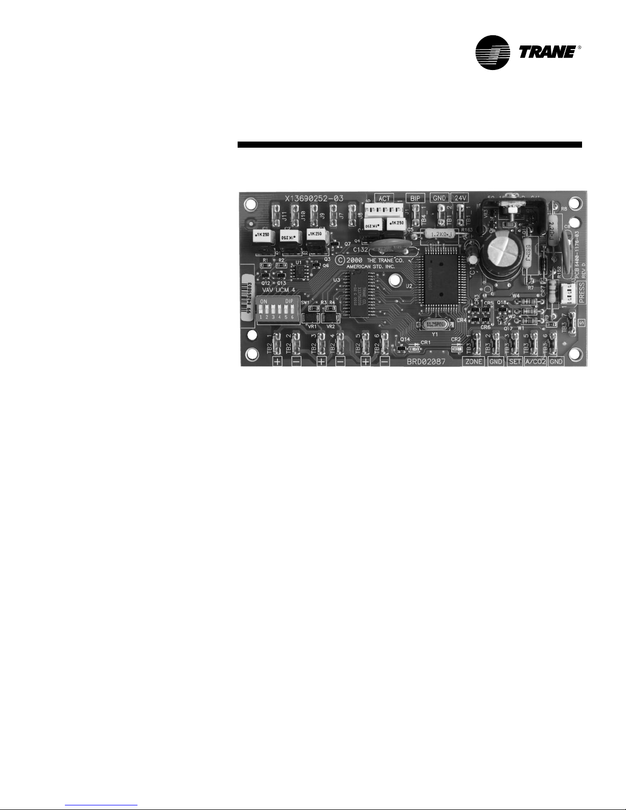
Wiring Diagram
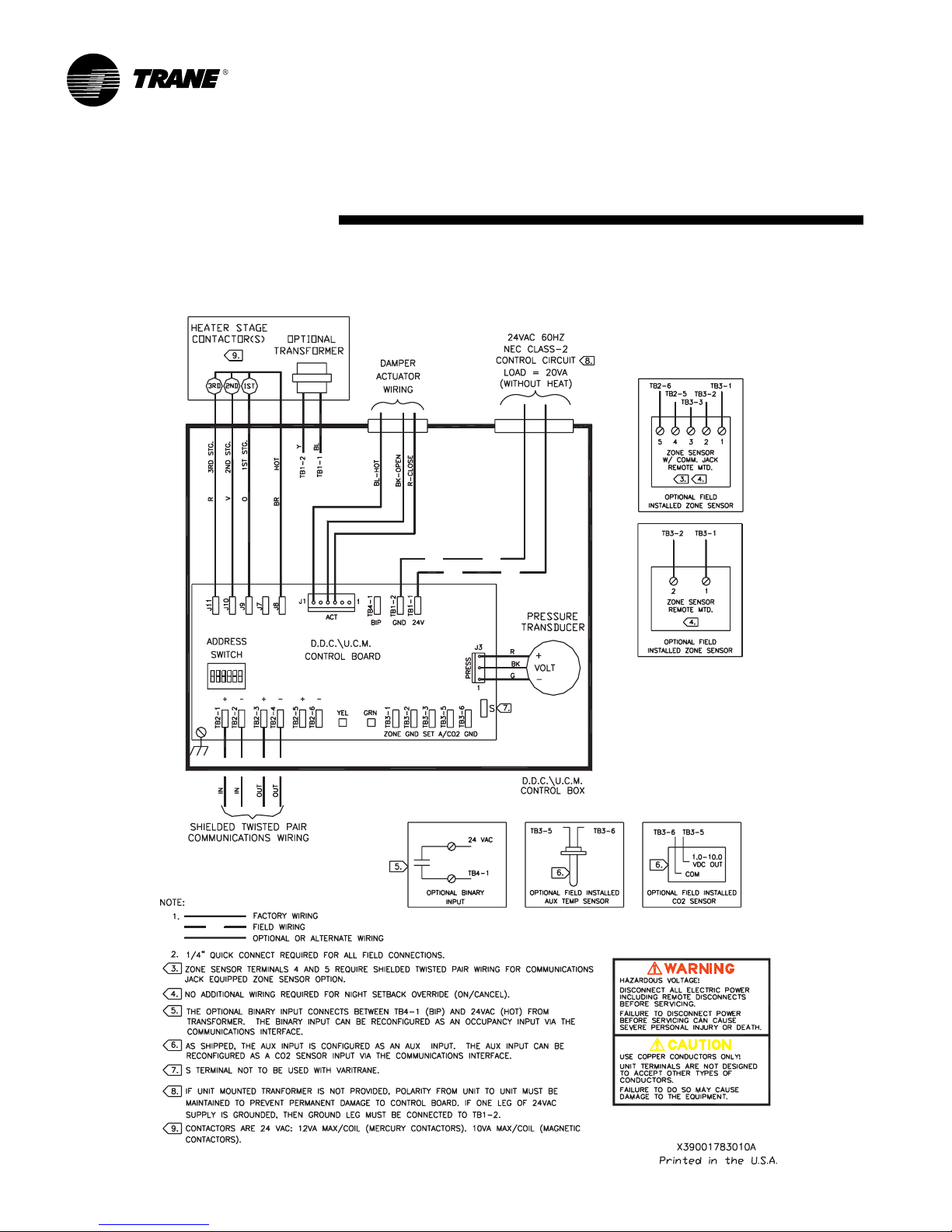
Figure 1 shows a typical wiring diagram
for the redesigned UCM hardware. The
new service part number is BRD 2087.
VAV-SVX01B-EN 5
Figure 1. UCM 4.0 Board Layout
Zone Sensor, Auxiliary Sensor, and
Thumbwheel Set Point Calibration
If there is a discrepancy between a
measured temperature and what the
UCM reports, a calibration offset value
can be edited in the UCM setup screen
to correct the displayed value.
Flow Sensor Calibration
If there is a discrepancy between a
measured flow and what the UCM
reports, the measured value can be
entered, which automatically calculates
a calibration multiplier to correct the
displayed value.
Water Valve Override
Each UCM that has proportional or
staged hot water heat outputs can be
edited to override the water valve to its
maximum position.
Ventilation Set Points and Ratio
Calculation
Set point values needed for a space to
satisfy indoor air quality requirements
are provided. A resultant ventilation
ratio can be used to calculate an air
handler’s outside air damper minimum
position or other control strategies.
Water Heat Output Configuration
UCMs that have hot water heat outputs
can be configured for normally open or
normally closed.
Zone Sensor Functions
Zone sensor functions now include: air
valve drive to maximum, use unoccupied set points, timed override, and
cancel timed override.
Slaving of Zone Sensors
Up to three (3) UCM 4.0s may be
connected to a single zone sensor.
Generic UCM Capability
UCM 4.0 can be configured to control
non-Trane VAV boxes.
Shipping
Each VAV product and its service
literature are shipped in the same
package. When unpacking, make sure
that the literature is not lost or discarded with the packing material.
Visually inspect the individual components for obvious defects or damage.
All components are thoroughly
inspected before leaving the factory.
Any claims for damage incurred during
shipment must be filed with the carrier.
Storage
When any component of the VAV
system and/or field installed accessories must be stored for a period of time
prior to being installed, they must be
protected from the elements. The
storage location temperature should be
between -40° – 150°F (-40°– 65.6°C) and
the relative humidity should be 10% to
90%, non-condensing.
The warranty will not cover damage to
the VAV system or controls due to
negligence during storage. A controlled
indoor environment must be used for
storage.
Page 6
VAV Start-Up/
Check-Out Procedure
Chapter Overview
This chapter contains information
pertaining to the following:
Pre-power up check-out for the UCM
4.0
UCM operational LEDs
Zone Sensor check-out
UCM 4.0 Pre-Power
Check-out
[ ]Check the supply voltage at TB1. Proper
polarity must be maintained. TB1-1 is
the hot side (+) and TB1-2 is the ground
side (-) of the 24 VAC input. The UCM
cannot be powered from a common 24
VAC transformer that is supplying
power to a device containing a fullwave rectifier bridge in its power
supply. The acceptable voltage is 20 to
28 VAC (24 VAC cataloged). However,
voltages at either extreme may result in
increased system instability.
[ ]Verify that communications wiring has
properly been terminated atTB2-1 (+)
and TB2-2 (-). Polarity is very important
on the communications link.
[ ]Verify that the zone sensor connections
are correct as detailed in the UCM
wiring chapter.
[ ]Verify that the proper unit DIP switch
settings have been set on each UCM.
[ ]Verify that the tubing is properly
connected to the transducer.
CHAPTER 2: VAV START-UP/CHECK-OUT PROCEDURE
Light Emitting Diode (LED)
Operations
The UCM has one green LED located
near TB3 and one yellow LED located
near TB2 on the UCM circuit board. These
LED’s are used to help diagnose communication (yellow) or circuit board problems (green).
The green LED (red on older boards) is a
power indicator. It is steady on when the
power is on and the software is
functioning correctly. If it blinks with a 1
second on 1 second off cycle when
power is applied, then the board is not
functioning and must be replaced.
Table 1 - Green LED Power Function Indication
LED State Indication
“On” Board functioning correctly
Blinking Board malfunction (Replace Board)
“Off” Board does not have power
The yellow LED functions as the
communication indicator. The indication
from the yellow LED is as follows:
Table 2 – Yellow LED Communication Indicator
Function
LED State Indication
“On” Incorrect (reversed)
Blinking slowly Communication is occurring on the
approx. 1 link but not for that particular UCM.
blink/sec.
Blinking quickly Communication is occurring on the
(multiple blinks link, specifically with that UCM.
blinks/sec.
“Off” Polarity is correct and no
communication polarity, no
connection, or shorted lines.
communication is occurring on the
link
Zone Sensor Check-out
If an erroneous temperature is being
reported to the UCM, use the Zone
Sensor Temperature-Resistance Table to
verify the integrity of the adjustable set
point potentiometer or sensor. The
resistance should be measured across
the terminals to which the device is
connected.
Note: Disconnect the zone sensor from
the UCM when making the checks listed
in the table below.
Table 3 – Zone Sensor Temperature-Resistance
Table
Temp. Resistance Resistance
(°F) (Ohms) (k Ohms)
55 792 17.0
56 772 16.5
57 753 16.1
58 733 15.7
59 714 15.4
60 694 15.0
61 675 14.6
62 656 14.3
63 636 14.0
64 617 13.6
65 597 13.3
66 578 13.0
67 558 12.6
68 539 12.3
69 519 12.1
70 500 11.8
71 481 11.5
72 461 11.2
73 442 11.0
74 422 10.7
75 403 10.4
76 383 10.2
77 364 10.0
78 344 9.7
79 325 9.5
80 306 9.3
81 286 9.0
82 267 8.8
83 247 8.6
84 228 8.4
85 208 8.2
Thermostat
Thumbwheel Sensor
6
Note: Thumbwheel resistance checks
are made at terminal 2 and 3 on the zone
sensor. Temperature sensor resistance is
measured at terminal 1 and 2 of the zone
sensor.
VAV-SVX01B-EN
Page 7
UCM 4.0 Installation
and Wiring
CHAPTER 3: UCM 4.0 INSTALLATION AND WIRING
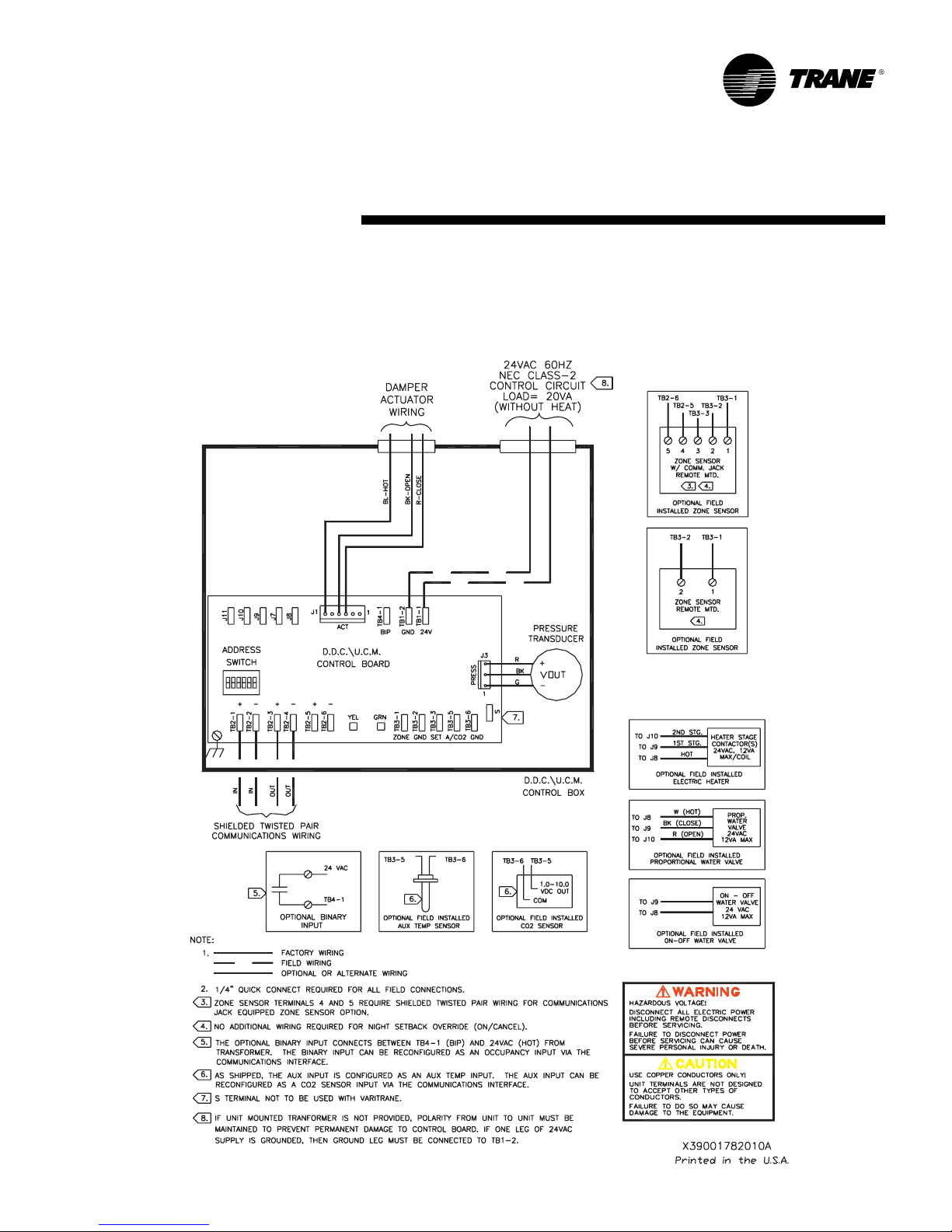
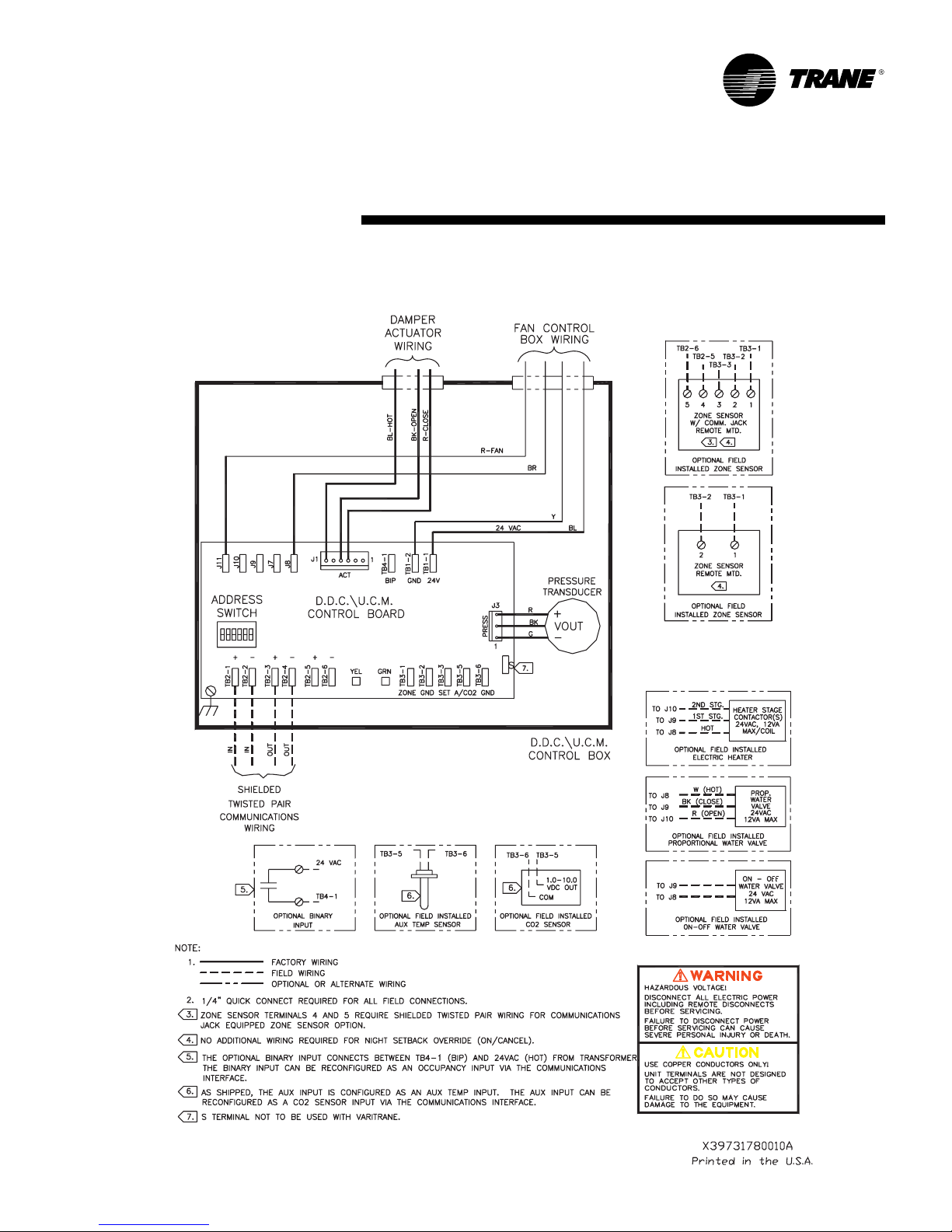
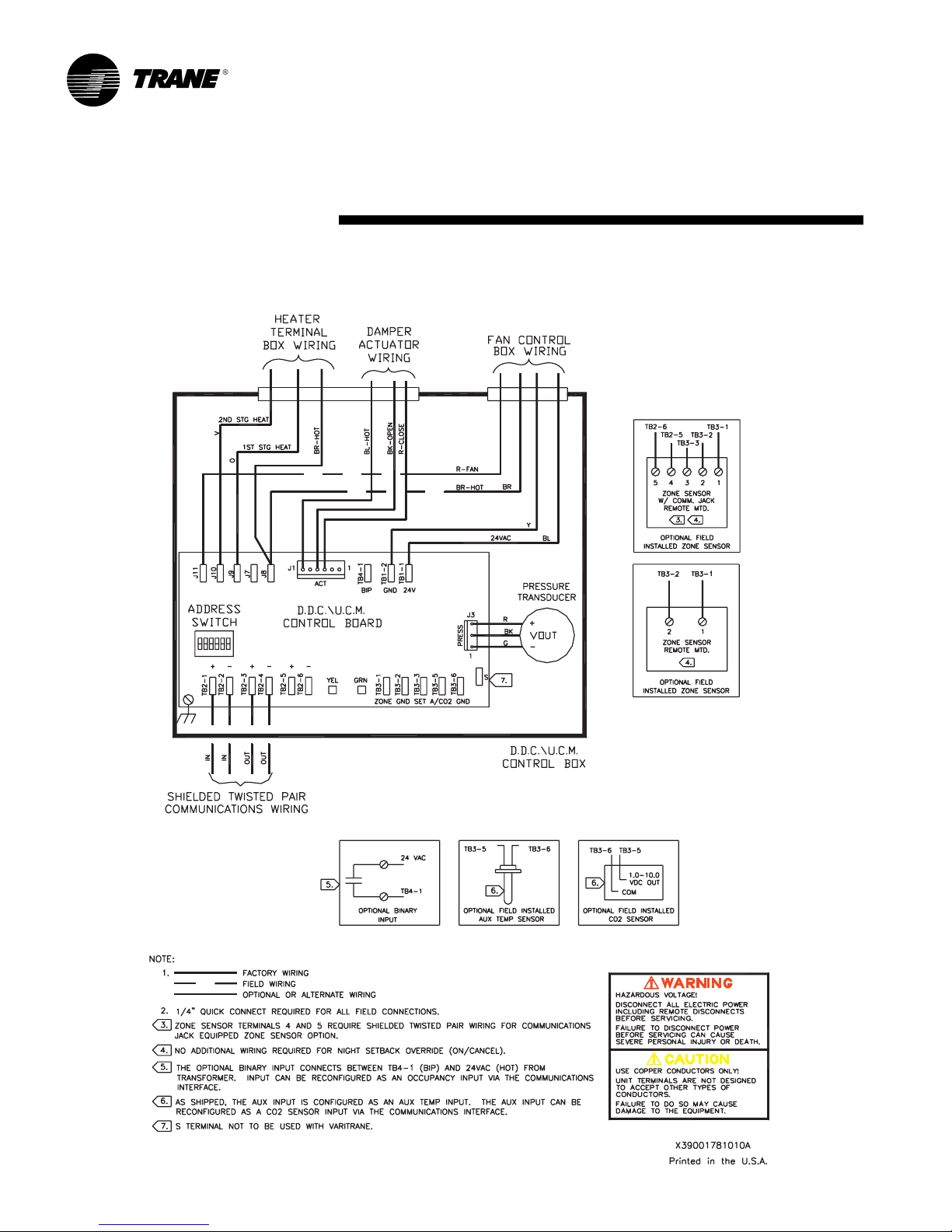
Figures 2 – 5 show wiring diagrams for typical applications of UCM 4.0
Figure 2. Wiring Diagram for Single Duct Units with Field Installed Re-heat
VAV-SVX01B-EN 7
Page 8
UCM 4.0 Installation
and Wiring
Figure 3. Wiring Diagram for Single Duct Units with Factory Installed Electric Re-heat
8
VAV-SVX01B-EN
Page 9
UCM 4.0 Installation
and Wiring
Figure 4. Wiring Diagram for Fan-Powered Units with Field Installed Re-heat
VAV-SVX01B-EN 9
Page 10
UCM 4.0 Installation
and Wiring
Figure 5. Wiring Diagram for Fan-Powered Units with Factory Installed Electric Re-heat
10
VAV-SVX01B-EN
Page 11

UCM 4.0 Installation
and Wiring
Chapter Overview
This chapter contains information
about the following:
UCM 4.0 Power Wiring
Zone Sensor Wiring
Communication Wiring
DIP switch Settingsire Selection
UCM 4.0 Power Wiring
Power Requirements
Caution: Disconnect all power external
to the unit to prevent injury or death
from electrical shock. Use copper
conductors only. The use of aluminum
or other types of wire may result in
overheating and equipment damage.
Use at least 16 AWG for power wiring
and connect to terminal TB1-1 (+) and
TB1-2 (-). 24 VAC is required to power
the UCM control and has an acceptable
voltage tolerance of 20 to 28 VAC.
Replace the UCM control box cover
after field wiring to prevent any
electromagnetic interference.
NOTE: A dedicated 24 VAC, 50VA NEC
class 2 transformer is recommended to
power the UCM. When powering
multiple UCM’s from one transformer,
polarity must be maintained. Terminal
TB1-1 is designated positive (+) and
terminal TB1-2 is negative (-) to the unit
casing ground. All wiring must comply
with the National Electric Code (NEC)
and local codes. Maximum wire lengths
should be based on NEC specifications.
The power consumption for cooling
only Series F Models (VariTrac and
VariTrane) is 12 VA (4 VA for the air
valve/actuator and 8 VA for the board).
Units with fans and/or reheat outputs
are rated at 10 VA maximum for
magnetic contactors and 12 VA
maximum for mercury contactors for
each output. To determine the total UCM
power requirement, add the power
consumption per stage to the circuit
board power requirement. For example,
a Series F unit containing magnetic
contactors with three stages of reheat
would consume 42 VA.
NOTE: VariTrane and VariTrac cooling only
Series D and E models consume 20 VA
(12 VA for the actuator and 8 VA for the
board). The heating output ratings
remain the same.
Refer to Figure 1 for UCM terminal
locations.
Zone Sensor Wiring
Location and Mounting
A zone sensor in each control zone
should be located in the most critical
area of the zone. Sensors should not be
mounted in direct sunlight or in the
area’s supply air stream. Subdivision of
the zone may be necessary for adequate control and comfort.
Avoid mounting zone sensors in areas
subject to the following:
Drafts or “dead spots” behind doors or
corners.
Hot or cold air ducts.
Radiant heat from the sun or
appliances.
Concealed pipes or chimneys.
Unheated or uncooled surfaces behind
the sensor such as outside walls.
Air flows from adjacent zones or other
units.
Wiring
Each unit must be controlled by a zone
sensor that is designated specifically
for use with the UCM control. Field
wiring for the zone sensors must meet
the following requirements:
Must be 14 to 18 AWG.
Refer to the sensor instructions for
terminal connections.
If local codes require enclosed
conductors, the zone sensor wires
should be installed in conduit. Do not
route zone sensor wires in conduit with
24 VAC or other high power conducting
wires.
Multiple UCM’s Per Zone Sensor
Up to three (3) UCM’s may be connected to a single zone sensor and
thumbwheel set point.
Connect terminal connections TB3-1,
TB3-2, and TB3-3 in parallel (i.e. daisy
chain) from the master UCM to the
slaved UCM(s). NOTE: Proper polarity
must be maintained.
Cut jumper wires W1 and W2 on the
slaved UCM’s (never cut jumper wires
W1 and W2 on the master UCM).
VAV-SVX01B-EN 11
Page 12
UCM 4.0 Installation
and Wiring
Multiple UCM’s per Auxiliary Duct
Temperature Sensor
Up to three (3) UCMs may be connected to a single auxiliary duct
temperature sensor.
Connect terminal connections TB3-5
and TB3-6 in parallel (i.e. daisy chain)
from the master UCM to the slaved
UCM(s). NOTE: Proper polarity must be
maintained.
Cut jumper wire W4 on the slaved
UCMs (never cut jumper wire W4 on
the master UCM).
Zone Sensor Options
Depending on the zone sensor options
used, a maximum of five wires may be
required to run from the UCM to the
zone sensor. The zone sensor options
are:
Zone sensor only (2 wires) – Part
Number X13510609-01.
Zone sensor with external adjustable
set point and communications jack (5
wires) – Part Number X13510606-01.
Zone sensor with external adjustable
night set back, timed override (TOV) on/
cancel button, and communications
jack (5 wires) – Part Number
X13510606-02.
Sensor with night set back, timed
override (TOV) on/cancel button, and
communications jack (4 wires) – Part
Number X13510606-03.
Digital zone sensor - Part Number
X13511067-01
NOTE: All wiring from the zone sensor to
the Com link must be twisted shielded
pair wiring.
Communication Wiring
Communication Link Wiring
The “Communication Link” is the
communication wiring between Tracer
Summit and all VAV box Unit Control
Modules (UCM). Tracer Summit
be connected to the UCM communication link in a “daisy chain” configuration.
®
can
Note: It is not necessary for each UCM
to be connected to the line in sequential
order by address. Also, multiple
communication links may be run and
terminated at the Tracer Summit.
However, a consistent, documented
wiring path will help troubleshoot
communication problems after
installation.
Field wiring for the communication
link must meet the following
requirements:
1. All wiring must be in accordance with
the National Electrical code and local
codes.
2.Communication link wiring must be at
least 18 AWG twisted shielded pair
wire. Shields must be grounded at the
Tracer Summit or Central Control
Panel (CCP) only. More than one
ground reference will cause
communications failures. Shields
must be daisy chained. Tape the shield
at the last VAV UCM to prevent any
connection between the shield and
ground. Wire specifications are as
follows:
Plenum Cable
Stranded, tinned copper insulated
with extruded FEP. Conductors cabled
and shielded with overall aluminum/
Mylar tape and stranded, tinned
copper drawn wire. Extruded jacket,
300 volt, 150°C NEC 725-2 (b) class 2,
type CL2P, 25 pF/ft.
Non-Plenum Cable
Stranded tinned copper insulated with
polyethylene. Conductors cabled and
shielded with overall aluminum/
polyester tape and stranded, tinned
copper drain wire. Chrome gray PVC
jacket, 300 volt, 60°C NEC type CM, 24
pF/ft.
Wire Capacitance
Wire capacitance must comply with the
following table:
Max. Communication Max.
Link Wiring Length Wire Capacitance
1,000 feet (304.8m) Up to 60 pF/ft. (196.9 pF/m)
2,000 feet (609.6 m) Up to 50 pF/ft. (164.0 pF/m)
3,000 feet (914.4m) Up to 40 pF/ft. (131.2 pF/m)
4,000 feet (1,219.2 m) Up to 30 pF/ft. (98.4 pF/m)
5,000 feet (1,524 m) Up to 25 pF/ft. (82.0 pF/m)
3.The maximum wire length should not
exceed 5,000 feet (1,524 m).
4.Communication link wiring cannot pass
between buildings.
5.A maximum of 63 UCMs can be
connected to each COM Link. Daisy
chaining is a typical configuration.
“STAR” chaining is also acceptable.
Note: Polarity is extremely important
and must be observed on communication link connections.
6.At the VAV box, communication link
wires must be connected to TB2-1, 3 (+)
and TB2-2, 4 (-) terminals on the UCM.
7. Verify that the UCM address is properly
set (DIP switch SW1). See Table 4 for
proper DIP switch settings.
12
VAV-SVX01B-EN
Page 13
UCM 4.0 Installation
and Wiring
DIP Switch Settings
DIP Switch SW1 contains six switches
for addressing the UCM. These
switches allow a user to set a unique
communication address for each UCM.
Each UCM on a given communication
link must have a unique address in
order for Tracer Summit or the CCP to
communicate to it. Refer to Table 3 for
UCM 4.0 DIP switch settings.
Note: When using Eware to communicate to the UCM, you must add 64 to the
DIP switch address. For example, a UCM
with the DIP switch address set to 1
would be UCM Number 65 in Eware.
Table 4 – DIP Switch Settings for UCM 4.0
UCM Eware
Unit # Address Dip 1 Dip 2 Dip 3 Dip 4 Dip 5 Dip 6
1 65 OFF ON ON ON ON ON
2 66 ON OFF ON ON ON ON
3 67 OFF OFF ON ON ON ON
4 68 ON ON OFF ON ON ON
5 69 OFF ON OFF ON ON ON
6 70 ON OFF OFF ON ON ON
7 71 OFF OFF OFF ON ON ON
872 ONONONOFFONON
9 73 OFF ON ON OFF ON ON
10 74 ON OFF ON OFF ON ON
11 75 OFF OFF ON OFF ON ON
12 76 ON ON OFF OFF ON ON
13 77 OFF ON OFF OFF ON ON
14 78 ON OFF OFF OFF ON ON
15 79 OFF OFF OFF OFF ON ON
16 80 ON ON ON ON OFF ON
17 81 OFF ON ON ON OFF ON
18 82 ON OFF ON ON OFF ON
19 8 3 OFF OFF ON ON OFF ON
20 84 ON ON OFF ON OFF ON
21 85 OFF ON OFF ON OFF ON
22 86 ON OFF OFF ON OFF ON
23 87 OFF OFF OFF ON OFF ON
24 88 ON ON ON OFF OFF ON
25 89 OFF ON ON OFF OFF ON
26 90 ON OFF ON OFF OFF ON
27 91 OFF OFF ON OFF OFF ON
28 92 ON ON OFF OFF OFF ON
29 93 OFF ON OFF OFF OFF ON
30 94 ON OFF OFF OFF OFF ON
31 95 OFF OFF OFF OFF OFF ON
32 96 ON ON ON ON ON OFF
33 97 OFF ON ON ON ON OFF
34 98 ON OFF ON ON ON OFF
35 99 OFF OFF ON ON ON OFF
36 100 ON ON OFF ON ON OFF
37 101 OFF ON OFF ON ON OFF
38 102 ON OFF OFF ON ON OFF
39 103 OFF OFF OFF ON ON OFF
40 104 ON ON ON OFF ON OFF
41 105 OFF ON ON OFF ON OFF
42 106 ON OFF ON OFF ON OFF
43 107 OFF OFF ON OFF ON OFF
44 108 ON ON OFF OFF ON OFF
45 109 OFF ON OFF OFF ON OFF
46 110 ON OFF OFF OFF ON OFF
47 111 OFF OFF OFF OFF ON OFF
48112 ONONONONOFFOFF
49 113 OFF ON ON ON OFF OFF
50 114 ON OFF ON ON OFF OFF
51 115 OFF OFF ON ON OFF OFF
52 116 ON ON OFF ON OFF OFF
53 117 OFF ON OFF ON OFF OFF
54 118 ON OFF OFF ON OFF OFF
55 119 OFF OFF OFF ON OFF OFF
56 120 ON ON ON OFF OFF OFF
57 121 OFF ON ON OFF OFF OFF
58 122 ON OFF ON OFF OFF OFF
59 123 OFF OFF ON OFF OFF OFF
60 124 ON ON OFF OFF OFF OFF
61 125 OFF ON OFF OFF OFF OFF
62 126 ON OFF OFF OFF OFF OFF
63 127 OFF OFF OFF OFF OFF OFF
VAV-SVX01B-EN 13
Page 14

UCM Programming
and Operation
Chapter Overview
This chapter contains information
about the following:
Typical UCM Operating Behavior
UCM Status
UCM Set Points
UCM Setup
CHAPTER 4: UCM PROGRAMMING & OPERATION
Typical UCM Operating
Behavior
VariTrac Bypass Damper Mode of
operation
In the VariTrac Bypass Damper mode of
operation, the decisions of damper
position are made by a higher-level
system controller, e.g., the VariTrac 4.0
Central Control Panel (CCP). The
VariTrac bypass mode supports the
reporting of supply air temperature
(SAT), supply air static pressure (SAP),
and supply air CO
(CO2). This mode supports the following:
Control of damper position from the
higher-level system controller.
The control of the damper to a failsafe
bypass position upon lack of
communication to the VAV UCM for a
period of one minute.
Damper calibration from the fully open
position while the system fan is off.
Upon power up, damper calibration
and then damper movement to its
failsafe bypass position.
By convention of the VariTrac 4.0
system, DIP switch setting of 63 has
been reserved for the VariTrac Bypass
Damper. Note: DIP switch setting 63 can
be used for non-VariTrac systems.
Typical UCM Operating Behavior
VariTrane and VariTrac (zone damper,
not bypass damper) Modes of
operation
Unoccupied Mode:
Zone temperature is controlled to the
unoccupied set points. If the AHU
system fan is off the valve will be
operating in a pressure dependent
mode.
Normally the minimum flow set point is
not enforced. This allows the control
algorithm to close the valve in response
to zone temperature and set points. If
the minimum flow set points are being
enforced the valve will position itself at
a percentage equivalent to the
minimum flow set point.
concentration
2
Morning Warm Up:
Tracer Summit places the UCM in heat
mode and drives the UCM to maximum
flow. The AHU system fan is turned on
and the UCM operates in pressure
independent mode and controls the
airflow to the maximum flow set point.
NOTE: VariTrac units
pressure dependent mode.
Morning Cool Down:
Tracer Summit places the UCM into
cool mode and drives the UCM to
maximum flow. The AHU system fan is
turned on and the UCM operates in
pressure independent mode and
controls the airflow to the maximum
flow set point. NOTE: VariTrac units
always operate in pressure dependent
mode.
Occupied:
Zone temperature is controlled to the
occupied set points. Set points are
determined from the local thumbwheel
if enabled.
Cooling:
Zone temperature is controlled to the
cooling set point. Both types of reheat
(hot water and electric) are available if
needed to keep the zone from cooling
below the heating set point.
Heating:
Zone temperature is controlled to the
heating set point. Hot water reheat will
always be available if needed to keep
the zone from cooling below the
heating set point. Electric reheat may be
permitted to turn on if using auto
changeover and the supply air temp (or
auxiliary temperature for stand-alone
units) is not too high.
The following table briefly describes the
typical behavior of various UCM
configurations during normal operating
modes.
always operate in
14
VAV-SVX01B-EN
Page 15

UCM Programming
and Operation
The following table briefly describes the typical behavior of various UCM configurations during normal operating modes.
Single Control to cooling Control to heating Tracer may place Tracer may place Control to cooling Control to heating
Duct setpoint. setpoint. UCM in max flow and UCM in max flow setpoint. setpoint.
Reheat All types of local Electric reheat is Electric reheat is All types of local All types of local Electric reheat is
Fan Fan runs until valve Fan runs until valve Fan on. Fan on. Fan on. Fan on.
Series is fully closed
Fan Fan off unless local Fan off unless local Fan off unless local Fan off unless local Fan on if needed Fan on if needed
Parallel reheat is on. reheat is on. reheat is on. reheat is on. for heat. for heat.
(temp.)
Fan Fan off unless local Fan off unless local Fan off unless local Fan off unless local Fan on if needed Fan off unless local
Parallel reheat is on. reheat is on. reheat is on. reheat is on. for ventilation or reheat is on.
(flow) reheat is on.
Cooling Heating Morning Warm Up Morning Cool Down Cooling Heating
reheat available to available if using auto available if using auto reheat available to reheat available to available if using auto
keep zone above changeover and the changeover and the keep zone above keep zone above changeover and the
heating setpoint. supply air temperature supply air temperature heating setpoint. eating setpoint. supply air temperature
reheat is off. reheat is off.
Unoccupied Transition to occupied Occupied
supplies hot air. and supplies cold
Control to heating air. Control to
setpoint. cooling setpoint.
(or auxiliary temperature) (or auxiliary temperature) (or auxiliary temperature)
is below 70
hot water reheat is hot water reheat is hot water reheat is
always available to always available to always available to
keep the zone above keep the zone above keep the zone above
the heating setpoint. the heating setpoint. the heating setpoint.
AND is fully closed AND
o
F. Local is below 70oF. Local is below 70oF. Local
VAV-SVX01B-EN 15
Page 16

UCM Programming
and Operation
Calibration of Flow Sensor and Position
of Valves (Air and Water)
Calibration that is initiated via a reset is
staggered to prevent duct over pressurization. The calibration process consists
of 2 steps:
1.Establishing the true valve position.
This is done by overdriving the valve
closed (open in the case when UCM4 is
configured for VariTrac Bypass Damper
Mode of operation) for 30 seconds
beyond the configured stroke time (water
valve stroke time plus 15 seconds).
2.Adjusting the D/A output to correct any
transducer offset.
The D/A output is fed into an op amp
along with the signal from the transducer
to remove any zero offset voltage from
the pressure transducer.
Communication Protocol Selection
UCM 4.0 can communicate using either
COM 3 or COM 4 protocols. The UCM will
automatically determine whether the
front-end system is a COM 3 or COM 4
device.
Adjustable Air Valve Stroke Times
Stroke times are adjustable for all units
over the communication link as long as
the communication protocol used is
COM 4. If the UCM is in COM 3 mode, the
stroke time is only configurable for
generic and VariTrane Series F configurations. Stroke times for non-generic, nonseries F COM 3 systems are hard coded
into the UCM for the following valves:
Series F All sizes 90 seconds
Series D & E Sizes 3, 6, and 11 6 min. 24 sec.
Series D & E Sizes 17, 24, 32, and 42 6 minutes
VariTrac Round 57 seconds
VariTrac Rectangular 60 seconds
Series C Sizes all but 20, 40 7 min. 12 sec.
Series C Sizes 20, 40 9.25 min.
Timed Override (TOV) Button Functions
There are two buttons that the user can
access. Pushing the timed override
button (on) in an unoccupied period
provides two hours of occupied control.
The UCM will switch into occupied mode
and control to the occupied set points for
two hours. The cancel button stops a
timed override sequence and returns to
unoccupied control. The UCM will revert
back to unoccupied mode immediately.
Timed override (TOV) and cancel
buttons are recognized if they have
been pushed for at least 0.5 seconds
and no more than 15 seconds. Pushing
the buttons for longer than 15 seconds
will simulate a zone temperature sensor
failure. The failure is non-latching and
ceases as soon as the button is
released.
“*” And “**” Functions
Also in conjunction with the
thumbwheel, the timed override button
can cause an override to maximum
flow or unoccupied. The TOV button
must be pushed for at least 2 seconds
and no more than 15 seconds with the
thumbwheel in one of the override
positions to recognize an override
condition. With the thumbwheel in the
“*” position an override to maximum
flow is generated. With the thumbwheel
in the “**” position an override to
unoccupied is generated. The maximum flow and unoccupied overrides
are held until the thumbwheel is moved
into the normal operating region.
Note: If the thumbwheel is not enabled,
locally generated overrides (“*” or “**”)
are not possible.
Local Occupancy detector.
Local occupancy detection was added
with UCM4 on input TB4-1. TB4-1 is a 24
VAC input operated in a negative logic
mode wherein the absence of signal
indicates occupancy and the presence
of 24 VAC indicates non-occupancy. The
occupancy detector’s interface is two
dry relay contacts. Relay closure (short
between two dry relay contacts and
presence of 24 VAC at TB4-1) shall
indicate unoccupancy. The VAV UCM
has a COM 4 configuration bit to
indicate if the VAV UCM has an occupancy sensor connected.
When configured for an occupancy
sensor and communications are active,
an occupancy input state will be
reflected by the UCM to an upper level
system controller. The upper level
system controller is responsible for
causing any system changes necessary
to provide occupied control.
When configured for an occupancy
sensor and communications are not
active and occupancy is detected, the
UCM shall transition to the occupied
mode of operation. Upon loss of the
occupancy indication from the
occupancy detector, the VAV UCM will
revert back to unoccupied mode.
When configured for an occupancy
sensor and communications are active,
loss of COM 4 communications does
not result in the VAV UCM defaulting to
occupied mode.
When configured as a generic input
and communications are active an
occupancy input state will be reflected
by the UCM to an upper level system
controller. The upper level system
controller shall be responsible for
causing any system changes necessary
to provide occupied control. When
configured for generic mode, loss of
COM 4 communications will result in
the UCM defaulting back into occupied
mode.
Reheat Control
Reheat operation is allowed provided
the following conditions are satisfied:
1. The unit is not calibrating.
2.Flow overrides (open or closed) are not
in affect.
3.Reheat lockout is not enabled.
4.If maximum flow override or fan
lockout is present then parallel fan with
any electric heat is not allowed.
5.If the zone temperature sensor has
failed cold (open), reheat is not allowed.
6.While in the heat mode only hot water
heat can be used. If using auto
changeover, UCM 3.3 and later will
enable electric heat in the heat mode if
the auxiliary temperature is less than
the electric heat on set point and will
disable electric heat when the auxiliary
air temperature is greater than the
electric heat off set point.
Modulating Hot Water Reheat
When the zone temperature reaches the
heating set point + 0.5°F the reheat is
turned completely off. The modulating
hot water valve is over driven closed
(by 15 seconds) any time reheat is no
longer required.
16
VAV-SVX01B-EN
Page 17

UCM Programming
and Operation
Pulse Width Modulation (PWM)
Pulse Width Modulation (PWM)
modulates 2 stages 0 to 100% with a 3minute time base. The first stage (J9) of
PWM modulates 0 to 100% to supply 0
to 50% of the reheat need. The second
stage (J10) modulates 0 to 100% to
supply 51% to 100% of the reheat need.
Hot Water Heat Maximum Override
(Maximum Heat Required)
A UCM with hot water outputs can be
commanded to override the water valve
position to maximum position. For
units with 1 - 3 stages hot water will
turn on all of its water outputs (possible
fan is not affected). For units with
proportional hot water the hot water
valve will be driven open, and if no fan
is present, output 3 (J11) will energize.
The hot water override can be commanded via communications and can
be used to assist in water balancing.
See Chapter 7 for Water Balancing
Procedure.
Auto Changeover
Auto changeover is based on zone
temperature and the supply air temperature as communicated or measured by the auxiliary temperature
sensor.
1. When the supply air temperature is 10
degrees above the zone temperature
the control action will be Heat.
2.When the supply air temperature is
below or equal to the zone temperature
the control action will be Cool.
3.If the supply air temperature is between
the zone temperature and the zone
temperature +10
supply air temperature < zone
temperature + 10
remains the same and the UCM
controls to the minimum flow set point.
Flow Overrides
During flow overrides of drive to
minimum or maximum the flow is
controlled to the appropriate set point.
With UCM 3.3 and prior during flow
overrides of open or closed, the valve is
continuously driven in that direction
forever. UCM 3.3 and prior rely on the
limit switches to protect the drive train.
UCM 4.0 drives for the stroke time, then
stops.
o
F (zone temperature <
o
F), the control action
Enforce Minimum Flow Set Points
The UCM can be told not to enforce the
minimum flow set point (energy saver)
via communications. This allows the
control algorithm to choose any value
from 0 to the maximum flow set point.
The primary use of this is VariTrac
systems, but it is available for any
configuration.
Calculated Cool Ventilation Ratio (Z
Factor)
As a measurement of zone ventilation,
a “Z” factor is computed and available
over communications (only if using the
COM 4 protocol). The UCM does not
use this value for any control purposes.
It is computed as follows:
Z = (Ventilation Target)/Sensed Flow
Where the ventilation target is
dependent on occupancy and ranges
from 0 to 100.
Z will be set to zero if the active
minimum flow set point is 0.
Z will be set to zero if the sensed flow
(or valve position) is 0.
If position control is being used the
sensed flow is replaced with the valve
position.
The Z factor may then be used by BAS
equipment to satisfy ASHRAE 62-89
and calculate the outside air flow set
point.
IAQ Set Point Modification
Ventilation rate change for IAQ purposes is accomplished by setting the
active minimum flow set point to the
edited cooling minimum flow set point
* IAQ multiplier when no heat is being
supplied to the zone. When heat is
being supplied (heat mode or reheat
active) the active minimum flow set
point is the greater of heating minimum
flow and cooling minimum flow * IAQ
multiplier. The result of cooling minimum flow * IAQ multiplier is limited to
the maximum flow set point. Reheat
continues to stage on/off based upon
the heating minimum flow set point.
The IAQ multiplier range is from 0.0 to
10.0 in tenths.
Wireless Compatibility
Up to five wireless sensors may be
assigned to a UCM. Four sensors may
be classed as “averaging”; one sensor
can be classed as “backup”. The
hardwired sensor is optional and can
be classified as:
“Averaging” (A peer with the averaging
wireless sensors)
“Primary Backup” (Supersedes any
backup wireless sensor)
“Secondary Backup” (Used only if the
wireless backup sensor is not
functional)
“Not Present” (UCM 4.0 only, UCM 3.3
and prior treated this selection the
same as Secondary Backup)
The backup sensors are optional.
Backup sensors for temperature and
set point inputs only affect the UCM if
all averaging sensors are failed. Backup
button functions are always used. Any
combination of backup strategies is
permitted.
Although the hardwired sensor is
optional in a wireless system, having
one provides valid set point and zone
temperature values for the UCM to use
during the time between a reset (power
cycle or via communication) and the
reception of the next wireless data
update. During this time, if there is no
hardwired sensor the zone temperature
used by the UCM is 0
and hardwired set point and zone
temperature will be indicated as failed.
In a wireless system with a hardwired
sensor enabled and configured as
averaging, primary backup or
secondary backup after a reset the
UCM will use the hardwired sensor
values until the wireless sensor values
are received.
Button pushes from any sensor
assigned to a UCM will be accepted
and used without regards to source,
(i.e., any assigned sensor can cause
any button function). The priority of
button pushes is: 1. Override to
maximum flow, 2. Override to
unoccupied, 3. Timed override, and 4.
Cancel. Any sensor that is generating a
local override will not be used to
calculate the local thumbwheel setting.
The UCM must receive an update from
a wireless sensor at least every 24
minutes for that sensor to continue to
affect the zone control. Sensors that do
o
F and the global
VAV-SVX01B-EN 17
Page 18

UCM Programming
and Operation
not update at least every 24 minutes will
be viewed as failed.
Composite zone temperatures and
thumbwheel settings are derived from
the transmitted data and the hardwired
sensor if applicable. Data for the zone
temperature and thumbwheel value
comes first from the averaging sensors
then the primary backup, then the
secondary backup. Zone temperature is
the simple average of the available
sensors. The thumbwheel setting is the
weighted average of the available
sensors.
zone temperature = (measured
temperature + zone temperature
correction)/(Number of sensors)
thumbwheel setting = ((thumbwheel
setting + thumbwheel
correction)*weighting factor))/(weighting
factor)
Flow (or Supply Pressure in the case of
bypass damper mode)
Each VAV valve contains a “flow ring.” It
is a multi-ported Pitot tube. The differential flow transducer connects to the flow
ring. One side of the flow ring is exposed
to the duct static pressure, the other is
exposed to static and velocity pressure.
The difference is velocity pressure. By
knowing the air velocity in the duct and
the size of the air valve, the air volume
can be calculated. See Chapter 7 for Air
Balancing Procedures.
UCM STATUS
The status display does not contain any
editable data. If Communications are
down (UCM NOT COMMUNICATING is
shown), the rest of the status display will
not appear. Note: The following screen
shots are taken from Trane EveryWare™
Software (Eware). When communicating
with a UCM 4.0 or greater via Eware,
you must have Eware software revision
1.35 or greater. The display will be similar
when using a CCP. However, when
communicating to VAV UCM using
Tracer Summit, although the display will
be completely different, the various
functions of the UCM perform the same.
Please reference the VariTrac Operators
Guide or the Tracer Summit System
Programming Guide (BMTW-SVP01AEN) for exact CCP and Summit (respectively) displays.
When viewed from the Eware, the UCM status display appears as follows:
Following are descriptions of each line on the UCM status screen.
Zone Temperature
This line displays the temperature as recorded by the zone sensor. If the zone sensor
has failed, this line will read FAIL.
Active Cooling Set Point and Active Heating Set Point
These set points are the active (actual) cooling and heating set points currently used
by the UCM. If the zone sensor is enabled, the zone sensor set point will be used as
the Active Cooling set point during occupied mode.
Control Mode
This line shows whether the UCM is in the occupied or unoccupied mode. The
control mode determines which heating and cooling set points to use.
Control Action
This line shows the heat or cool control action of the UCM. The cool control action
will modulate the air valve as if the supply duct air is colder than the space temperature. The heat control action will modulate the air valve opposite the cool control
action (supply duct air is warmer than the space temperature).
Flow
This line displays the unit’s airflow rate expressed in the flow units selected in the
setup menu. This line will not be shown if the UCM is using position control instead
of flow control. The UCM will use position control if the flow sensor is failed or not
installed. The UCM will also use position control if the unit’s airflow rate is less than
5% or greater than 110% of the unit’s cataloged CFM. For example, the UCM will use
position control for a size 600 CFM unit if the flow is less than 30 CFM (5%) or greater
than 660 CFM (110%). NOTE: Although the UCM will read flow down to 5% of
cataloged and up to 110% of cataloged, the range of MIN FLOW settings is 0%, or
10% to 100% of cataloged. The range of MAX FLOW settings is 100% of cataloged. In
the example above, the lowest allowable MIN FLOW set point is 60 CFM (zero is also
permissible) and 600 CFM is the highest allowable MAX FLOW set point.
Flow Control
This line displays the actual flow control override of the UCM. These overrides can be
AUTO, OPEN, CLOSED, MIN, and MAX.
Position
This line displays the UCM’s air valve position.
18
VAV-SVX01B-EN
Page 19

UCM Programming
and Operation
Present Minimum
If the UCM is using flow control, this
line will show the present minimum
expressed in the flow units selected in
the setup menu. If the UCM is using
position control, the minimum will be
expressed as the percentage open.
Ventilation Ratio
The ventilation ratio is equal to the
“outside air requirement” divided by
the air valve flow. The UCM set points
screen provides entry for the occupied
and unoccupied outside air requirement.
Zone Sensor Set Point
This line will not be shown if the zone
sensor thumbwheel functions have
been edited to DISABLE on the UCM
setup menu nor on zone sensors
without the thumbwheel.
The following describes what may be
displayed on this line:
Zone sensor set point 70.1
This text displays the current zone
sensor set point.
Zone sensor set point MAX
This text will be displayed if “*” appears
on the zone sensor thumbwheel and
has been overridden to MAX (“*”
means the high limit and TOV
pushbutton have been depressed).
Zone sensor set point UNOCC
This text will be displayed if “**”
appears on the zone sensor
thumbwheel and has been overridden
to UNOCC (“**” means the low limit
and TOV pushbutton have been
depressed).
Zone sensor set point FAIL
Displayed if no zone sensor module is
supplying the UCM with a valid set
point.
Unit Type, Heat Type, and Fan Type
These lines show the different types of
units, the type of heat and the type of
fan. Further descriptions of these types
are found under the UCM setup
section.
Auxiliary Temperature
The displayed value will reflect the
auxiliary sensor temperature. This field
will not be shown if the unit does not
have an auxiliary sensor.
Software Revision
This line shows the version of the UCM
firmware that is being used.
The following lines will only appear if
the condition exists:
UCM Memory Failure
This text will be displayed if the UCM’s
EEPROM has failed.
Calibrating
This will be displayed if the UCM is
calibrating. The UCM will calibrate after
a power-up or as commanded by an
ICS device.
Control Offset Active
This line will be shown if the control
offset is currently being used. It will
only be shown if the edited occupied
set points are being used and the
control offset is active for the UCM.
Max Hot Water Override
This line will be shown if Max hot water
override is edited to YES on the UCM
setup menu.
UCM SET POINTS
In Eware, the UCM set points display
appears as follows:
Following are descriptions of each line
on the UCM set points screen.
Active Cooling Set Point
Active Heating Set Point
The set points cannot be edited and
reflect the set points currently being
used for temperature control.
Occupied Cooling Set Point
Occupied Heating Set Point
Both set points have a range of 30.0°–
100.0°F (-1.1° – 37.8°C). If a zone sensor
thumbwheel set point is not being
used, these set points will be used as
the UCM’s active set points during
occupied times. The cooling set point
must be greater than or equal to the
heating set point plus 2.0°F (1.1°C).
NOTE: Occupied cooling and heating set
points must be set within the cooling set
point high limit and the heating set point
low limit in order to control to the proper
set points.
Unoccupied Cooling Set Point
Unoccupied Heating Set Point
Both set points have a range of 30.0° –
100.0°F (-1.1° – 37.8°C). These set points
are used when the UCM is unoccupied.
The unoccupied cooling set point must
be greater than or equal to the unoccupied heating set point plus 2.0°F (1.1°C).
VAV-SVX01B-EN 19
Page 20

UCM Programming
and Operation
NOTE: Unoccupied cooling and heating
set points must be set within the cooling
set point high limit and the heating set
point low limit in order to control to the
proper set points.
Cooling Set Point Low Limit
Heating Set Point High Limit
These limits apply to both occupied and
unoccupied modes of operation. Both
limits have a range of 30.0° – 100.0°F
(-1.1° – 37.8°C). The set point limits will
be applied to the active set points by
the UCM but will not restrict operator
entry of set points.
NOTE: These limits are allowed to cross
(i.e. the cooling set point low limit can be
greater than, less than, or equal to the
heating set point high limit).
The UCM will enforce these limits
regardless of the source of the active
set points.
Cooling Set Point High Limit
Heating Set Point Low Limit
These limits apply to both occupied and
unoccupied mode. Occupied and
unoccupied cooling and heating set
points are subject to high and low
limits. The cooling set point high limit
and the heating set point low limit
“cap” your unoccupied set points,
which directly impacts energy savings.
The upper level device is responsible
for preventing the resulting set points
from being crossed. This may happen if
the heating set point low limit is above
the cooling set point high limit. Having
the cooling set point high limit and the
heating set point low limit set to the
factory defaults (cooling high limit =
102°F, heating low limit = 43°F) should
prevent them from impacting field
operation.
Heat Offset
The set point has a range of 2° – 10°F
(1.1° – 5.6°C). When a zone sensor
thumbwheel set point is being used, the
cooling set point will equal the zone
sensor thumbwheel set point and the
heating set point will equal the zone
sensor set point minus the Zone
Sensor Heating Set Point Offset. The
offset will always be displayed and will
always be editable even if a zone sensor
set point is not being used.
Control Offset Value
The Control Offset has a range of 0° –
5°F (0° – 2.8°C). When Control Offset is
active, this value will be added to the
edited occupied cooling set point and
subtracted from the edited occupied
heating set point to determine the
active set points.
Note: The control-offset value will not
effect a zone sensor thumbwheel set
point.
Fan Control Set Point
The entry on this line determines when
a parallel fan will be turned ON and OFF.
If “Parallel fan control” has been edited
to “DEG” the fan control offset will be
entered as a temperature offset (2° –
10°F) which will be added to the heating
set point. If “Parallel fan control” has
been edited to “FLOW” this line will be
entered as a percent (0 to 100%) if the
unit is a VariTrane unit. The entry field on
this line will appear as “—“ if the unit
does not have a parallel fan.
BP Failsafe Position
This setting only applies to VariTrac
Bypass mode of operation. If the CCP
stops communicating with the Bypass
Damper UCM for more than 60
seconds, the UCM will drive to the
failsafe position.
BP Command Position
This setting only applies to VariTrac
Bypass mode of operation. The CCP
uses this parameter to set the proper
position of the Bypass damper.
Maximum Flow/Position
This range is 10% to 100% of the unit’s
cataloged CFM size. Cooling and
heating flow can be edited to zero.
Minimum Flow/Position
Although the UCM will read flow down
to 5% of cataloged, the range of MIN
FLOW settings is 0%, or 10% to 100% of
cataloged.
Min Heating Flow
The UCM will not drive its position/flow
below this value under normal operating conditions while in the HEAT mode
(warm air in the supply duct) or while it
is using local heat. The Min Heating
Flow value must be less than or equal
to the Maximum Flow value. If the Min
Local Heat Flow is enabled, then the
Min Local Heat Flow is used to determine the minimum position/flow
instead of the Min Heating Flow when
local heat is on.
Min Local Heat Flow
This input allows a separate heating
minimum flow set point to be used for
local reheat. When local reheat is on,
your active minimum flow can not be
less than your minimum local heat flow
set point.
20
VAV-SVX01B-EN
Page 21

UCM Programming
and Operation
UCM SETUP
In Eware, the UCM SETUP display appears as follows:
The following are descriptions of each line on the UCM setup screen.
Unit Type
The possible Unit Types are, VariTrac Rectangular, VariTrane F Rectangular, VariTrane F
Round, Bypass-Damper Rectangular, Bypass Damper Round, Generic, VariTrane D,
VariTrac Round, and VariTrane C.
Editing the unit type will affect the following:
Heat type (defaults to NONE)
Fan type (defaults to NONE)
Unit size (defaults to the smallest unit size)
Air Valve drive time
Control algorithm gains (KP, reset times, valve flow constant) for air valve and water
valve.
Note: This means that the unit type should be edited before any of the items in the list
are edited.
Heat Type
The heat type assignment identifies what kind of heat control algorithm is to be used
by the UCM. Possible selections include the following:
NONE – No heat available
1-3 stages electric
Slow pulse width modulation – Electric (3 min. time base).
Prop hot water and aux. output
1-3 stages hot water/perimeter
If the unit type is edited, the heat type will automatically be changed to NONE. If the
heat type is edited or changed automatically, all 3 of the UCM outputs will be set to
Normally Open and the “Max hot water override” will be canceled if it is active.
Fan Type
This entry identifies the fan type to be
controlled by the UCM (None, Series or
Parallel) and shows whether the unit’s
fan has been enabled or disabled. The
enable/disable field on this line will not
appear if the unit has a series fan and
only indicates if the parallel fan has
been disabled. The UCM may lockout
the fan on its own if any of the following
apply: control action HEAT; flow
override to drive OPEN, CLOSE, or
MAX; or if the zone temperature sensor
has failed.
NOTE: This line will not appear if the unit
does not have a fan.
BIP Configuration (Default is Generic)
The BIP Configuration interface is for
dry relay contacts. There are two modes
of operation available at TB4-1, Generic
BIP and OCC Detector. In generic mode,
the state of the input is only passed on
from the UCM to Summit. CPL code
must be written in order for Summit to
utilize any signal received from this
generic input. When configured as a
generic input and communications are
active, an occupancy input state will be
reflected by the UCM to the upper level
system controller. The upper level
system controller shall be responsible
for causing any system changes
necessary to provide occupied control.
When configured for generic mode,
loss of communications will result in
the UCM defaulting back into occupied
mode.
In occupancy detector mode, the
absence of a 24 VAC signal at TB4-1
indicates occupancy and the presence
of 24 VAC indicates non-occupancy.
When configured for an occupancy
sensor and communications are active,
an occupancy input state will be
reflected by the UCM to an upper level
system controller. The upper level
system controller shall be responsible
for causing any system changes
necessary to provide occupied control.
When configured for an occupancy
sensor and communications are not
active and occupancy is detected, the
UCM shall transition to the occupied
mode of operation. Upon loss of the
occupancy indication from the
VAV-SVX01B-EN 21
Page 22

UCM Programming
and Operation
occupancy detector, the VAV UCM will
revert back to unoccupied mode.
However, when configured for an
occupancy sensor and
communications are active, loss of
communications does not result in the
VAV UCM defaulting to occupied mode.
Unit Size
The unit size range is dependent on the
unit type selected.
Use Local Heat Set Point (Default is No)
When “No” is selected, the UCM will
use the Min Heating Flow. When “Yes”
is selected, the UCM will use the Min
Local Heat Flow Set Point. See UCM set
points for more information regarding
Min Heating Flow and Min Local Heat
Flow Set Points.
Thumbwheel Set Point
If DISABLE is selected, the following
features of the UCM’s zone sensor
thumbwheel functions will be disabled:
set point; ability to generate a “drive to
max” command; ability to generate a
“go unoccupied” command.
Note: Disabling thumbwheel functions
does not disable the ON/Cancel
pushbutton feature.
Aux Input Select (Defaults to Aux Tmp
Sensor)
This entry determines the configuration
of the A/CO
the UCM. Selecting AUX TMP SENSOR
configures the input to use an auxiliary
temperature sensor. Selecting CO
Sensor configures the input to use a
CO2 sensor.
Parallel Fan Control
This entry will determine if a parallel fan
will be controlled based on zone
temperature or on flow conditions. If
“Parallel fan control” has been edited to
“DEG” the fan control offset will be
entered as a temperature offset (2° –
10°F) which will be added to the heating
set point. If “Parallel fan control” has
been edited to “FLOW” this line will be
entered as a percent (0 to 100%) if the
unit is a VariTrane unit. The entry field on
this line will appear as “—“ if the unit
does not have a parallel fan.
input on terminal TB3-5 of
2
2
Note: See the Sequence of Operations
section of this manual for details on
parallel fan operation.
Auxiliary Temperature
The current auxiliary temperature will
be displayed on this line. If the auxiliary
temperature sensor has failed or is not
present, “—“ will be displayed instead
of the temperature.
Output “X” Normally
These lines will always be shown as
Normally Open or Normally Closed, but
can only be edited if the heat type is “1-3
stages hot water”. If the unit has a fan,
output 3 will be set to Normally Open
and will not be editable. If output 3 is
not controlling a fan, it is editable for
proportional hot water units. If the unit’s
heat type is changed, all of the outputs
will be set Normally Open.
Aux Temp Calibration
This line allows an auxiliary temperature calibration offset to be entered with
a range of -10.0°– 10.0°F (-5.6° – 5.6°C).
The UCM will add the offset to the value
being read by the UCM’s auxiliary
temperature sensor. For example, if the
auxiliary temperature sensor is indicating that the temperature is 74°F (23.3°C),
and the auxiliary temperature calibration offset is -1.5°F (-0.8°C), the actual
temperature used by the UCM and
reported to the ICS will be 72.5°F
(22.5°C).
Wired Zone Temperature
This is the temperature being reported
by the zone sensor. The temperature
will be displayed with the temperature
calibration offset applied. If the temperature sensor has failed or been
disabled, “—“ will be displayed instead
of the temperature.
Wired Zone Temp Calib
The zone sensor calibration offset has a
range of -10° – 10°F (-5.6° – 5.6°C). The
temperature will be displayed with the
temperature calibration offset applied.
The UCM will add the offset to the value
being read by the UCM’s zone temperature sensor. For example, if the temperature sensor is indicating that the
temperature is 74.0°F (23.3°C) and the
temperature calibration offset is -1.5°F
(-0.8°C), the actual temperature used by
the UCM and reported to the ICS will be
72.5°F (22.5°C).
Max Hot Water Override
Entering YES for this line forces the
UCM to turn on all of its hot water
outputs or drive open its proportional
hot water valve. This may be useful for
water system balancing (see Chapter 7
for water balancing information).
Only units with the following heat types
will be affected:
1-3 stages hot water
All three of the heat outputs will be
energized. If the unit has a fan, output 3
will not be affected.
Proportional hot water and aux. output
The hot water valve connected to
outputs 1 and 2 will be driven open.
Output 3 will energize if it is not
controlling a fan.
The UCM will maintain the “Max hot
water override” condition over power
failures. The only way to cancel a “Max
hot water override” is by editing this
line to NO.
If the unit does not have “1-3 stages hot
water” or “proportional hot water and
aux. output”, “—“ will be displayed
instead of the ON/OFF descriptor.
Note: Unit heat must be enabled in
order for the Max hot water override to
be effective.
Wired Thumbwheel Set Point
This is the set point being reported by
the zone sensor. The set point will be
displayed with the set point calibration
offset applied. If the zone sensor has
failed or been disabled, “—“ will be
displayed instead of the set point.
Flow Override
The flow override entered on this line
has the highest priority of all the flow
overrides (group, binary inputs, or
upper level system functions). Possible
entries include AUTO, OPEN, CLOSED,
MIN, and MAX. When a non-auto flow
override is edited from the UCM level,
the flow override will be maintained
over power failures. See Sequence of
Operations for more information.
22
VAV-SVX01B-EN
Page 23

UCM Programming
and Operation
Wired Thumbwheel Calib
The thumbwheel calibration offset has
a range of -10° – 10°F (-5.6° – 5.6°C). The
set point will be displayed with the set
point calibration offset applied. The
UCM will add the offset to the value
being read by the UCM’s thumbwheel.
Cooling Flow Correct
Present Cooling Flow
Measured Cooling Flow
This Present Cooling Flow shows the
current flow being reported by the
UCM. If the Present Cooling Flow is
incorrect, the operator can enter the
Measured Cooling Flow and the
Cooling Flow Correct calibration factor
will automatically be recalculated. For
example, if a measured flow indicates
330 CFM, and the UCM’s flow sensor
reports 300 CFM, the measured flow
(330) can be entered, which will calculate a calibration factor of 1.10. If the
UCM is using position control, the
current flow reported by the UCM
should be 0 and any entry on the line
will generate an “Entry too large.” See
Chapter 7 for more information.
Wired Sensor Type
This line is used to edit the type of
temperature sensor being used. The
sensor type can be selected as either
Thermistor or RTD. Note: Factory
supplied sensors are Thermistors.
Wired Sensor Use
This input determines the function of
the wired zone temperature sensor.
Select Averaged to use the sensor as
part of a wired system OR to use the
sensor as an averaging sensor in a
wireless system. Average will use the
sensed temperature in the temperature
averaging calculation and set point
temperature will be averaged according
to the set point vote. If this is the only
sensor the average will be the sensed
temperature. Backup means the UCM
will use this temperature only if the
primary sensor assigned to the UCM
has stopped communicating. First
backup means the UCM will look for a
wired sensor first if the wireless sensor
fails. Second backup means the UCM
will look for a wireless backup sensor
first if the wireless sensor fails. Select
not used if no sensor is present or to
ignore the wired zone sensor.
Wired Set Point Vote
Set point vote determines the weighting
of the set point vote. The range is 0-9.
This number represents the number of
votes the sensor gets when the set
points are averaged. If “0” is selected
the sensor gets no vote.
VAV-SVX01B-EN 23
Page 24

Sequence Of
Operations
Chapter Overview
This chapter describes the sequence of
operation of the available unit types.
Unit operation during the available
override commands will also be
described. This chapter contains
sequence of operations pertaining to
the following:
Single Duct Units
Parallel Fan-Powered Units
Series Fan-Powered Units
Zone sensor functions
Flow Sensor
Failure Modes
24
CHAPTER 5: SEQUENCE OF OPERATIONS
Single Duct Units
When the UCM control action is COOL,
the UCM controls the modulation of the
air valve as a cooling source to maintain the “active cooling set point”.
Airflow is varied between the minimum
and maximum flow set points to
maintain temperature set points. A PI
control algorithm is utilized to minimize
the measured difference between the
active zone set point and the actual
zone temperature.
It is possible for units to utilize electric
or hot water heating coils to maintain
temperature set points. After the
temperature loop calls for minimum
cooling flow and the zone temperature
is at or below the heating set point,
these units shall control to their
respective “Minimum Heating Flow”.
Once this “Minimum Heating Flow” is
established, heat is allowed to operate
according to the “Heat Control Type”
specified for the controller. For electric
heat units, this heating minimum flow
set point must be at or above 20% of
the unit cataloged airflow. Electric heat
may be pulse width modulation or
staged electric heat. Staging has the
following ON and OFF switch points.
UCM 3.3 and later allow hot water to
turn on regardless of flow/position.
Stage ON Switch point Off Switch point
1 At the heating 0.5°F above the
set point heating set point
2 1°F below the 0.5°F below the
heating set point heating set point
3 2°F below the 1.5°F below the
heating set point heating set point
Hot water heat control may be either
ON/OFF or proportional. ON/OFF hot
water is activated on the same schedule
as staged of electric heat.
Utilization of the “Heating Minimum
Flow” set point allows separate
minimum flows to be active depending
on whether or not the unit heat is
active.
Override Conditions
Unoccupied
If the control mode is unoccupied
(either as edited by software or as
determined by the binary input), the
unoccupied cooling and heating
temperature set points are used for
temperature control. Heat outputs
remain active.
Heating
If the control action is edited to HEAT,
the UCM controls the air valve as a
heating source rather than cooling.
Electric reheat is available the supply air
temperature (or auxiliary temperature)
is below 70
always available to keep the zone above
the heating set point. The “Heating
Minimum Flow Set Point” will set the
minimum flow.
Flow Control Override
Flow control may be overridden by any
of the following commands:
Drive Air Valve Fully Open
The air valve will be fully open and heat
outputs disabled.
Drive Air Valve Fully Closed
The air valve is driven fully closed and
heat outputs disabled.
Drive Air Valve to Minimum Flow
The air valve is driven to the minimum
airflow set point. The heat outputs
remain operational.
Drive Air Valve to Maximum Flow
The air valve is driven to the maximum
airflow set point. The heat outputs
remain operational.
Heat Control Override
Heat control can be disabled, locking
out heat outputs.
Control Offset
Control offset may be enabled, which
adjusts the edited cooling and heating
set points.
Recalibrate (Reset)
The recalibrate function can be enabled.
If enabled, the unit will perform a
recalibration.
(Single Duct)
The UCM occupied controls can be
overridden by the following override
commands:
o
F. Local hot water reheat is
VAV-SVX01B-EN
Page 25

Sequence Of
Operations
Fan-Powered Units
Fan Actuation Schedule
FAN TYPE OCCUPIED UNOCCUPIED
Series ON OFF if valve closed
Parallel based on Cool mode: ON if zone temp Cool mode: OFF if zone OFF unless local
Temperature <heating set point + fan temp > heating set point + reheat is on
Parallel based Cool mode: ON if flow < fan Cool mode: OFF if flow > OFF unless local
on Flow set point OR if flow < active fan set point + 5% AND reheat is on
Parallel Fan-Powered Units
Occupied Units
Air valve control for parallel fanpowered units is the same as for single
duct units.
The first heat output is utilized to
control the fan. The remaining outputs
are utilized to control heat. Fan
energization is a function of the
“Parallel Fan Control Offset”. The
parallel fan control can be specified as
an offset temperature in degrees above
the heating set point or as a flow offset
in CFM. The fan will be energized above
the fan control offset if reheat is
required.
offset fan offset + 0.5°F Heat mode: fan off unless
Heat mode: fan off unless reheat is on
reheat is on
minimum flow set point flow > active minimum
Heat mode: fan off unless flow set point
reheat is on Heat mode: fan off unless
reheat is on
Heat stages are energized on the
following schedule:
Stage ON Switch point OFF Switch
point
1 At the heating 0.5°F above the
set point heat set point
2 1°F below the 0.5°F below the
heat set point heat set point
Whenever the fan is energized, the
primary airflow is controlled at the
“Heating Minimum Flow” set point.
Override Conditions
(Parallel Fans)
The UCM occupied controls can be
overridden by the following override
commands:
Note: The fan control offset is entered in
CFM when used on a VariTrane unit.
If the fan control is based on flow, the
unit fan will be energized whenever
primary airflow is below this set point.
For this parallel fan configuration, the
fan control point, if specified in a
percentage of unit airflow, must be set
between 15% and 30% of the units
cataloged airflow to assure proper
operation. A differential of 5% exists to
avoid excessive fan cycling.
When the fan control offset is in terms
of a temperature above the heating set
point, the fan shall be energized
whenever the zone temperature is
below the heating set point plus the fan
control offset. A differential of 0.5°F
shall apply to this switch over to avoid
fan cycling.
Unoccupied
If the control mode is unoccupied, the
unoccupied cooling and heating
temperature set points are used for
temperature control. Fan and heat
outputs are activated at the unoccupied
heating set point.
Heating
If the control action is HEAT, the UCM
controls the air valve as a heating
source rather than cooling. Fan and
heat outputs are disabled for parallel
units with electric heat. If the heat type
is hot water heat, then the fan will
remain on if the heat is on during the
heating control action.
Flow Control Override
Flow control may be overridden by any
of the following commands:
Drive Air Valve Fully Open
The air valve will be driven fully open.
Fan and heat outputs are disabled.
AND reheat off
Drive Air Valve Fully Closed
The air valve is driven fully closed. Fan
and heat outputs are disabled.
Drive Air Valve to Minimum Flow
The air valve is driven to the minimum
airflow set point. The fan and heat
outputs remain operational.
Drive Air Valve to Maximum Flow
The air valve is driven to the maximum
airflow set point. The fan and electric
heat outputs are disabled (hot water
heat remains enabled).
Heat Control Override
Heat control can be disabled, locking
out heat outputs.
Fan Control Override
Fan control can be disabled, locking out
both fan and heat outputs. This affects
only parallel fan-powered units.
Control Offset
Control Offset may be enabled, which
adjusts the edited cooling and heating
set points.
Recalibrate (Reset)
The recalibrate function can be enabled.
Series Fan-Powered Units
Occupied Units
Air valve control for series fan-powered
units is the same as both single duct
and parallel fan-powered units.
During the occupied mode of
operation, the series fan is continuously
energized. Heat stages are energized on
the following schedule:
Stage ON Switch point OFF Switch point
1 At the heating 0.5°F above the
set point heating set point
2 1°F below the 0.5°F below the heat
heat set point set point
Override Conditions
(Series Fan)
The UCM occupied controls can be
overridden by the following override
commands:
Unoccupied
If the control mode is edited to unoccupied, the unoccupied cooling and
heating temperature set points are used
for temperature control. The series fan
and heat outputs will be activated as
VAV-SVX01B-EN 25
Page 26

Sequence Of
Operations
necessary to maintain the current
unoccupied set points. The fan control
point is not utilized on series units. On
electric heating and hot water heating
units, the fan and heat are energized at
the unoccupied heating set point. The
minimum cooling flow set point is reset
to zero unless minimums are being
enforced by a group override. A series
fan will be energized anytime the air
valve’s position is greater than 0%.
Heating
If the control action is edited to HEAT,
the UCM controls the air valve as a
heating source rather than cooling. The
unit fan remains operational. Unit heat
on an electric heat unit is locked out,
but remains active on hot water units.
Flow Control Override
Flow control may be overridden by any
of the following commands:
Drive Air Valve Fully Open
The air valve will be driven fully open.
Fan operation is unaffected, but heat
outputs are locked out.
Drive Air Valve Fully Closed
The air valve is driven fully closed. The
fan and heat outputs are locked out.
Drive Air Valve to Minimum Flow
The air valve is driven to the minimum
airflow set point. The fan and heat
outputs remain operational.
Drive Air Valve to Maximum Flow
The air valve is driven to maximum
airflow set point. The fan and heat
outputs remain operational.
Heat Control Override
Heat control can be disabled locking
out heat outputs.
Fan Control Override
Fan control override does not affect fan
operation on series fan-powered units.
Control Offset
Control offset may be enabled which
adjusts the edited cooling and heating
set points.
Recalibrate (Reset)
The recalibrate function can be enabled.
Zone Sensor Functions
The zone sensor utilizes a thermistor
element to measure zone temperature.
The zone sensor has the following
options:
Zone Temperature
Each zone sensor module includes a
zone temperature sensor.
Set Point
A UCM will only use the zone sensor
thumbwheel set point (during occupied
time) if “Zone sensor thumbwheel
functions” is edited to ENABLE on the
UCM setup screen.
ON Timed Override (TOV) and CANCEL
Timed Override (TOV)
The ON (TOV) and CANCEL (TOV)
commands can be issued by pressing
the ON or CANCEL buttons on any of
the UCM zone sensor modules.
When an ON button on a zone sensor
is pressed (shorting the zone
temperature sensor circuit), the UCM
will set a TOV signal, clear the TOV
cancel signal if it is set, and start the
two hour timed override timer. The TOV
signal will be maintained for two
minutes.
When a CANCEL button on a zone
sensor module is pressed for at least
two seconds, the UCM must set a TOV
cancel signal, clear the TOV signal if it is
set, and set the timed override timer to
zero.
Pressing any zone sensor module’s ON
or CANCEL button will not affect the
zone temperature reported from the
UCM.
Note: TOV pushbuttons should be
pressed for at least 2 seconds and not
more than 15 seconds.
Drive to Max and Go Unoccupied
When a zone sensor thumbwheel is
turned to its high-end limit, indicated by
a “*” on the thumbwheel, and the ON
button is pressed, the UCM will initiate
a “Drive to Max” command. When a
zone sensor thumbwheel is turned to
its low limit, indicated by a “**” on the
thumbwheel, and the ON button is
pressed, the UCM will initiate a “Go
UNOCCUPIED” command. The UCM
will maintain the command until the
zone sensor set point is adjusted to
within the range of 50° to 85°. Any zone
sensor module that has a thumbwheel
and ON (TOV) button can initiate these
commands.
Notes:
The UCM will not send these
commands if “Zone sensor
thumbwheel functions” is edited to
DISABLE on the UCM setup screen.
When an ICS is connected to the UCM,
the UCM will pass the commands to
the ICS without taking any control
action of its own. Since this is true, it
may take a minute or so after the
command is initiated before the UCM
actually goes unoccupied or is driven to
maximum.
The UCM will not generate a TOV signal
when a Drive Max or Unoccupied
command is initiated.
Pressing the ON button will not affect
the zone temperature reported from the
UCM.
The UCM will remain in the Drive Max
or Unoccupied status over power
failures IF “*” or “**” (respectively)
have been initiated prior to the power
failure.
Note: TOV pushbuttons should be
pressed for at least 2 seconds and not
more than 15 seconds.
Flow Sensor
The flow control is pressure independent utilizing the VariTrane flow-sensing
ring. The flow ring provides one of the
most accurate differential pressure flow
measurements in the industry by
averaging pressure differentials across
16 sensing points. These sensing
points, arranged in a ring configuration
to compensate for various inlet duct
configurations, provide a signal
accurate to within +/-5% of cataloged
CFM provided there is 1½-inlet diameters of straight ductwork upstream of
the VAV box.
The pressure differential signal from
the flow ring is then converted to an
electrical signal, which is utilized in the
control algorithm of the unit controller.
It is recommended that the recalibrate
sequence be initiated on a weekly basis.
Assuming ½ inlet diameters of straight
duct work and proper system
recalibration, total system flow
26
VAV-SVX01B-EN
Page 27

Sequence Of
Operations
measurement accuracy (flow ring,
transducer, and UCM controller) during
the occupied mode should be +/- 8% of
cataloged airflow over the typical
operating range of 20% to 100% of unit
cataloged airflow.
Failure Modes
Each UCM has diagnostic capabilities,
which allow it to sense various failure
conditions. This diagnostic capability
aids in maintenance and trouble
shooting of the system. Along with
reporting these failure conditions, the
UCM will follow a pre-programmed
operating sequence designed to
maintain zone comfort during a failure.
The failure conditions and backup
operating sequences are explained
below.
Temperature Sensor Failure
Failure of a zone temperature sensor
(open or below low limit of 0°F (-17.8°C))
will cause fan and heat outputs to be
disabled and airflow to be controlled to
the minimum cooling flow set point. If
the measured temperature fails above
the high limit (short or above 100°F
(37.8°C)), the airflow shall be controlled
to the maximum flow set point.
Flow Sensor Failure
If a flow sensor failure is reported
(open, short, fails calibration, or is out
of the normal range of 5% to 110% of
box cataloged), the UCM will immediately revert to a position-based,
pressure dependent control algorithm.
This allows full operation of the unit
and maintains the ability to control the
zone temperature. If a flow sensor has
failed, it is periodically checked for
proper operation. If found to be
operating properly, the UCM will be
switched to the standard pressure
independent control. Otherwise,
position control is used as long as the
flow signal remains out of range.
Local Thermostat Set Point Failure
Failure of a local thermostat set point
adjustment potentiometer will cause
the UCM to revert to the edited occupied cooling and heating set point.
Communications Failure
A fifteen-minute failure in communications between the UCM and Tracer
Summit will cause the UCM to:
Operate in the occupied mode
(provided that no occupancy sensor is
present on input TB4-1).
Set the IAQ multiplier to 1.0.
Disable the control offset.
Use the control action as determined by
the auxiliary sensor. The auxiliary
temperature is compared to the zone
temperature. If the supply air
temperature is 10
zone temperature, then the control
action will be heat. If the supply air
temperature is less than or equal to the
zone temperature, the control action
will be cool. If the supply air
temperature is between the zone
temperature and the zone temperature
o
F (zone temperature < supply air
+10
temperature < zone temperature +
o
F), the control action remains the
10
same and the UCM controls to the
minimum flow set point.
If an auxiliary sensor is not installed and
the VAV unit is not under Tracer Summit
control, the UCM will retain the last
control action in effect.
o
F
greater
than the
VAV-SVX01B-EN 27
Page 28

Air Balancing and
Water Balancing
Chapter Overview
This chapter contains information
about the following:
VAV air balancing
VAV water balancing
CHAPTER 6: AIR BALANCING & WATER BALANCING
Air Balancing
After the unit has been mounted and all
electrical and duct connections have
been made, the air distribution system
should be balanced. The proper variable
air volume balancing procedures
depend on the type of VAV system used
and the options specified on the
VariTrane unit. This section will cover
the basic balancing procedures and
calibrations needed to balance an air
distribution system using VariTrane
units. This section suggests only one
balancing procedure. Since there are
many possible air balancing procedures, keep in mind that these procedures are only suggestions.
Note: Before performing these balancing
procedures, the calibration command
should be initiated at least 15 minutes
prior to the balancing procedure.
1.System Checkout
Check the VAV system installation for
conformity to design.
Walk the entire system from air
handling equipment to the terminal unit
to determine variations of installation
from the plans.
Check for inadvertent obstructions in
the ductwork (such as closed fire
dampers).
Insure that any turning vanes, filters,
and dampers (both volume and fire) are
installed in the correct position.
There should be a 1.5 duct diameter
long run of straight ducting into the
valve.
Set the outside air dampers to their
minimum position.
Start the supply and return air fan(s).
2.Before we can balance the system, we
need to ensure that there is enough
CFM for all zones.
A.Drive all VAV boxes MAX.
Starting with each individual branch
duct, open all the VAV units in that
branch duct to the maximum cooling
position.
This can be done using EveryWare by
giving each UCM a “Drive Max”
command or by rotating the Zone
sensor set point knob to the “ * “
position, and hold the TOV ON button
for two seconds.
The damper will remain at its maximum
set point until the zone sensor knob is
moved back into the normal operating
range.
B.Read airflow at the most remote unit.
In most systems, this will be the VAV
unit located furthest from the fan.
This will be the unit in the system that
will be critical from an air delivery
set point.
A.If airflow is not adequate, increase the
supply fan CFM to achieve adequate
airflow.
B.Make the required adjustments to
pulley sizes, motor sizes and electrical
connections to accommodate fan-
speed changes.
3.With all VAV boxes fully open, take a
measurement of the total CFM.
CFM is determined by using this flow
signal and the chart on the side of the
unit (different size units have different
charts).
If the CFM is at or above design, the
system can now be balanced. If the
measured CFM is below design, insure
the VariTrane unit is in full cooling
position.
If the air delivery through this VariTrane
unit is still below the design
requirements, the supply fan rpm
should be increased until the correct
design airflow is obtained or the fan
reaches its maximum capacity.
If after adjusting the fan to its maximum
capacity there is still a shortage of
airflow, shut off part of the system to
provide enough airflow to balance the
other part of the system. This can be
done using the “Override to
Unoccupied” command (“**”) at the
zone sensor.
4.After determining that there is enough
CFM for all zones, drive all the VAV
boxes to MIN.
28
VAV-SVX01B-EN
Page 29

Air Balancing and
Water Balancing
Note: If the VAV boxes have already been
assigned to groups and these groups are
separate thermal zones, then the
balancing can be done on a group basis.
5.Select a group to balance and give that
group a flow override Drive MAX
command.
Note: If the VAV boxes have not been
placed in a group, each individual UCM
can be overridden to Drive MAX in the
UCM Setup Menu. However, this will be
more time consuming.
6.Adjust each VAV box maximum flow
set point required for its zone using the
UCM set points menu.
7. After balancing a group/box, return that
group/box flow override to AUTO.
Continue to the next group/box
repeating steps 6 through 8 until each
unit is delivering the correct CFM.
8.Upon completion of the VAV air
balancing:
Remove all overrides.
Initiate a recalibrate command.
Water Balancing
Each VAV UCM can have its hot water
valve overridden to drive fully OPEN (2position and proportional). This can be
done in the UCM setup menu and can
be used to assist in water balancing.
1. Log on to the UCM with EveryWare
software.
2.Select a VAV box to balance, and drive
its hot water valve open (max hot water
override).
3.Using hydraulic pressure gauges,
measure the flow across the high and
low ports. Convert this data from a
pressure differential to gallons per
minute (GPM).
4.Adjust the circuit setter until it is within
design specifications.
5.Once achieved, lock the circuit setter in
place. Mark the position with a
permanent indicator.
6.Remove all gauges and software
overrides.
7. Initiate a recalibrate command.
VAV-SVX01B-EN 29
Page 30

Wireless VAV
Systems
Chapter Overview
This chapter describes the wireless
zone sensor system including system
layout, component functionality, and
specifications.
CHAPTER 7: WIRELESS VAV SYSTEMS
General Information
Spread Spectrum
Trane Wireless VAV Systems apply
spread spectrum technology to
accomplish wireless communication.
Spread spectrum technology is a
technique for spreading a data signal’s
information over a frequency range that
is substantially larger than is required,
thus increasing the redundancy of the
communication. Upon reception, the
receiver “unspreads” the signal and
reads the information. Any receiver that
does not have a matching encoding
sequence can not unspread the signal
and sees the transmission as RF noise.
This spreading and unspreading
enhances the security of the system
and its ability to operate in the same
environment as other systems using
the same frequencies.
The sensor/transmitter simultaneously
broadcasts identical information over
two separate frequencies (911 and 918
MHz), making interference even less
likely.
Purpose of the Wireless System
The wireless system is a method for
eliminating the problems associated
with a wired sensor such as having to
run wire through solid or decorative
walls or having to move the sensor
after the occupant has redecorated the
space. The benefits are the flexibility in
system design and sensor location.
Zone sensor operation with wireless
offers some new capabilities. The first
feature is averaging. If more than one
sensor is assigned as an averaging
sensor to a UCM their temperature
readings are averaged. This gives the
ability to get a more accurate sample of
a large space supplied by one VAV box.
It also provides better control when 1
VAV box serves multiple zones such as
small offices. Under the averaging
scheme, the local set point requests are
also averaged. The set point average
can be weighted by changing the set
point Vote value from 0 to 9. The
number assigned represents the
number of votes the sensor gets. A
Value of “0” removes this sensor from
the set point voting scheme.
For example:
Sensor Value Vote Value
T1 75 x 3 = 225
T2 65 x 1 =
Calculation: 290/4 = 72.5°F Final Set Point Value
This allows someone who is more
affected by the temperature or in an
area that has a varying load such as
cold or hot outside walls to have more
impact on the set point.
An additional capability of the system is
the ability to use a sensor as a backup
to another sensor. If the primary sensor
stops communicating for some reason
the UCM automatically begins using
the backup sensor input.
Another added feature is the ability to
assign one sensor to multiple boxes.
This is a function of the way the sensor
transmits its information.
When the sensor broadcasts its
temperature it also sends the serial
number, the set point and the battery
Set Point Set Point Extended
Total 4 290
65
30
Figure 6. Wireless Zone Sensor and Receiver
VAV-SVX01B-EN
Page 31

Wireless VAV
Systems
status. Each receiver that receives this
signal checks to see if any of the UCMs
on its VAV link needs that sensor’s
value. If a UCM needs the value the
receiver sends the information down
the link and the UCM reads it. This
process means all UCM’s could use the
same sensor.
Specifications
Wireless Receiver Power Requirements
Input Voltage Connections: The receiver
requires 24 VAC and 60 HZ from a
dedicated 40 VA transformer (not
provided with the receiver).
Blue Wire: 24VAC (HOT wire)
Yellow Wire: 24VAC (NEUTRAL wire)
Green Wire: Earth GROUND
Red Wire: To Positive (+)
Communication Link
Black Wire: To Negative (-)
Communication Link
NOTE: A dedicated 24 VAC, 40VA class 2
transformer is required to power the
Wireless Receiver. Failure to comply will
result in malfunction of the Receiver due
to electrical noise.
All wiring must comply with the
National Electric Code (NEC) and local
codes. Use 16 AWG for power wiring.
Maximum wire lengths should be
based on NEC specifications.
Zone Sensor Power Requirements
The zone sensors require two 3-volt “2/
3 A” lithium batteries. Each sensor
ships with two batteries, and the
average expected battery life is approximately 1.5+ years.
NOTE: Excessive transmissions will
shorted the battery life span. See
Frequently Asked Questions for more
details.
Both batteries must be installed for
sensor/transmitter to operate properly.
Acceptable replacement battery model
numbers are Varta 123A, Panasonic
CR123A, or Duracell 123A.
Wireless Receiver Mounting
The receiver will work best if mounted below the ceiling grid with the antennae
pointing down. The receiver is to be hung from the roof structure like a light fixture. A
hook on the back is provided for connection of a chain. A threaded nipple is provided
for attaching a handy-box when the wiring must be run in conduit.
Ideally, the receiver should be located an equal distance from all its assigned zone
sensors.
NOTE: Do not mount the wireless system near RF barriers such as elevators. Failure to
do so may result in wireless system malfunction.
Zone Sensor Mounting
Zone sensors are installed in areas where temperature control is to be maintained.
The sensor mounts directly to the wall by either using Velcro or by attaching the
backplate and then snapping the sensor body into place.
Dimensions
Receiver Sensor
Enclosure: Sheet metal/Plastic Plastic
Height: 2.5” (64 mm) 4.0” (102 mm)
Width: 8.5” (216 mm) 5.0” (127 mm)
Depth: 9.0” (229 mm) 1.5” (38mm)
Product Specifications
At least one (1) wireless receiver is required per com link
Receivers per CCP: 6
Receivers per Tracer Summit: 31
Total Zone Sensors per CCP or Tracer Summit: 255
Backup Zone Sensors per VAV box: 1
Averaging Zone Sensors per VAV box: 4
Zone Sensors associated with one VAV box: 5
Maximum number of VAV UCMs per link: 63
Maximum Distance from Receiver to Sensor: 1000ft.(304 m)
Minimum Time between Transmission: 30 sec
Loss of Sensor Communications Alarm: 24 min
Average Battery Life: 1.5 years
Use 18 gauge twisted shielded pair communications wire for the ICS communication
link to the receiver. The communications link is polarity sensitive.
VAV-SVX01B-EN 31
Page 32

Wireless VAV
Systems
NOTE: A dedicated 24 VAC, 40VA NEC
class 2 transformer is required to power
the Wireless Receiver. Failure to comply
will result in malfunction of the Receiver
due to electrical noise.
All wiring must comply with the
National Electric Code (NEC) and local
codes. Use 16 AWG for power wiring.
Maximum wire lengths should be
based on NEC specifications.
General Information
Zone Sensor Range:
Cataloged 1000 feet (304 meters) lineof-sight, indoors
Receiver Setup/Normal Switch:
DIP switch 8.
Receiver RJ11 Jack:
Jack for temporary connection of an
external sounder for test purposes.
Receiver Sounder:
Built-in Piezo sounder
Receiver VAV Link Wiring:
The Receiver must be daisy-chained
into the VAV link wiring that connects
all of the UCMs and Tracer Summit. As
specified in Chapter 2, the VAV link
wiring must be twisted shielded pair. A
pigtail is provided for wiring. The red
wire is positive, the black wire is
negative, and the green wire is shielded
Figure 7. Receiver Wiring Connections
ground. Polarity must be maintained
throughout the VAV link.
Wireless System Architecture
Wireless Zone Sensor
The wireless zone sensor is designed
for use in a temperature control
system, operating in conjunction with a
centrally located Wireless Receiver.
Zone sensors are installed in areas
where temperature control is to be
maintained and are responsible for
transmitting temperature, set point, and
the On/Cancel command to the
receiver. The zone sensor measures
temperature and periodically transmits
that information via RF signals to its
assigned receiver.
Wireless Receiver
The receiver is designed for use in a
temperature control system, operating
in conjunction with wireless zone
sensors, which are installed in areas
where temperature control is to be
maintained. The receiver functions as a
communications translator between
the spread spectrum radio communications and the VAV communications link.
As a Spread Spectrum Receiver, the
device receives, correlates and decodes
a spread spectrum coded transmission.
The serial number of the transmitting
device is checked against a list of valid
serial numbers field programmed into
the Translators by the Tracer BAS
system user. The receiver maintains this
list of valid serial numbers. If the
transmission is valid, the message will
be transmitted over the Trane VAV link.
RF signals from wireless zone sensors
are received by the receiver, which then
sends appropriate messages via
communication wires to specific
heating and air conditioning equipment
assigned to it. This information is also
sent to a central controller for system
monitoring.
Note: A minimum of one receiver per
communication link is required.
Unit Control Module (UCM)
After the zone temperature is received
by the Receiver from the wireless zone
sensor module and broadcast over the
VAV Communication link, the UCM
receives the message packet. The UCM
accepts only those messages having a
sensor serial number that matches the
serial number field programmed into it.
Zone sensor serial numbers are
maintained by the UCM.
Upon receipt of the zone temperature
value, local set point, or On/Cancel
requests, the UCM will take the
32
VAV-SVX01B-EN
Page 33

Wireless VAV
Systems
appropriate action. In addition, a
twenty-four minute timer is initiated. If a
new zone temperature value is not
received within this time, a sensor
failure indicator is generated.
If all the averaging sensors have failed
and a backup zone sensor serial
number was programmed into the
UCM, the zone temperature value, set
point, and On/Cancel status from that
sensor will then be used for control. The
UCM will continue to monitor the link
for the averaging sensor information. If
received, normal operation is restored
and the sensor failure indicator cleared.
While in many cases a single sensor
and backup sensor are programmed in
the UCM, it is also possible to define up
to three additional optional zone sensor
serial numbers. The UCM will then use
the average of all of the programmed
sensors (except the backup sensor) as
the value representing the space
temperature. Values from sensors that
have been flagged as not reporting
within the last fifteen minutes will not
be used in the calculation. While an
averaging scheme is used to determine
the space temperature when multiple
sensors are used, a weighted average
scheme is used to determine the set
point. This scheme allows the user to
select the relative priority of each zone
sensor for the purpose of determining
the desired set point. However, any of
the sensors may be used to initiate On/
Cancel requests.
Wireless System Installation
Building Location
The receiver should be located centrally
to all of the zone sensors. Large
ductwork, metal covered walls or
reinforced concrete can block the signal
and should be avoided. Elevator shafts
are typically sources of interference and
therefore should also be avoided.
Maximum range is 1000 feet (304.8 m)
line of sight indoors (a maximum of 500
feet (152.4 m) total is recommended).
Setting the Receiver Address
The address is set using the DIP
switches mounted on the receiver. The
receiver is a “COM 4” master and does
not replace a UCM address. Up to 6
receivers may reside on a Communica-
tion Link when using a CCP and up to 31 receivers may reside on a Communication
Link when using a Tracer Summit.
DIP switches 6 and 7 are not used and should be set to their “ON” position. DIP
switch 8 is the setup/normal switch and is only used when the unit is being assigned
sensors using the set-up tool. When assigning zone sensors to the receiver using the
set-up tool, set DIP switch 8 to the Off (Down) position. During normal operation, DIP
switch 8 should be in the ON (Up) position. The following chart shows the switch
positions for addresses 1 through 31.
Table 5 – VAV Wireless Receiver DIP Switch Settings
UCM VAV Wireless Receiver DIP Switch Settings
Address DIP 1 DIP 2 DIP 3 DIP 4 DIP 5 DIP 6 DIP 7 DIP 8
1 OFF ON ON ON ON ON ON ON*
2 ON OFF ON ON ON ON ON ON*
3 OFF OFF ON ON ON ON ON ON*
4 ON ON OFF ON ON ON ON ON*
5 OFF ON OFF ON ON ON ON ON*
6 ON OFF OFF ON ON ON ON ON*
7 OFF OFF OFF ON ON ON ON ON*
8 ON ON ON OFF ON ON ON ON*
9 OFF ON ON OFF ON ON ON ON*
10 ON OFF ON OFF ON ON ON ON*
11 OFF OFF ON OFF ON ON ON ON*
12 ON ON OFF OFF ON ON ON ON*
13 OFF ON OFF OFF ON ON ON ON*
14 ON OFF OFF OFF ON ON ON ON*
15 OFF OFF OFF OFF ON ON ON ON*
16 ON ON ON ON OFF ON ON ON*
17 OFF ON ON ON OFF ON ON ON*
18 ON OFF ON ON OFF ON ON ON*
19 OFF OFF ON ON OFF ON ON ON*
20 ON ON OFF ON OFF ON ON ON*
21 OFF ON OFF ON OFF ON ON ON*
22 ON OFF OFF ON OFF ON ON ON*
23 OFF OFF OFF ON OFF ON ON ON*
24 ON ON ON OFF OFF ON ON ON*
25 OFF ON ON OFF OFF ON ON ON*
26 ON OFF ON OFF OFF ON ON ON*
27 OFF OFF ON OFF OFF ON ON ON*
28 ON ON OFF OFF OFF ON ON ON*
29 OFF ON OFF OFF OFF ON ON ON*
30 ON OFF OFF OFF OFF ON ON ON*
31 OFF OFF OFF OFF OFF ON ON ON*
Power Checkout
The receiver has three (3) LEDs.
Green (Power/operational)
Yellow (Radio communication activity)
Red (VAV Link activity)
The green LED will remain on to indicate steady power. The yellow LED will flash to
indicate the receiver is receiving radio communication for the sensors. The red LED
will flash to indicate the receiver has passed the information to the VAV link.
The zone sensor has one (1) LED. It is located next to the service tool connection at
the bottom of the sensor. Pressing the ON or Cancel buttons causes a transmission
to occur and the green LED should flash. This indicates the sensor has power and
should be transmitting.
VAV-SVX01B-EN 33
Page 34

Wireless VAV
Systems
Programming and Operation
Wireless Receiver Setup Using Tracer Summit
1. To setup the Receiver, go to the Main Menu of the Tracer Summit.
2. From the Main Menu, select the Setup Pull Down Menu and select the Site Configuration option.
3. Highlight the site name to be configured to enter the site configuration editor
4. Select the Devices tab.
5. Highlight the BCU to be modified and select the Create UCM Editor. See Figure 8.
6. Select the Non-Isolated link, which has the receiver connected to it. See Figure 9.
7. Change the UCM Type from Absorption Chiller (UCP2) to Wireless Receiver. See Figure 9.
8. Give the receiver a unique name, address, and specify how many receivers are going to be added to the network. See Figure 9.
9. Click the create button.
10. Click the save button to save the changes to the BCU.
Figure 8: Site Configuration, Devices Tab
34
VAV-SVX01B-EN
Page 35

Wireless VAV
Systems
Figure 9: Create UCM’s Dialog
Select a Non-Isolated Com 4 Link.
Select the Wireless
Receiver UCM Type.
Name the Wireless Receiver,
select and address, and specify
the quantity of Receiver UCMs
to create.
Click here to create the
Wireless Receiver UCM(s)
Wireless Receiver Summary Using Tracer Summit
This option only shows up after the wireless receiver has been setup as described above. This option will show the summary of the
information that the receiver is receiving, including zone sensor number (the serial number), TR Time Sec. (Time since the last
transmission was received in seconds) and RSSI (Receiver Signal Strength Indication). TR Time should not exceed 420 and RSSI
should be between 30 and 255. If TR exceeds 1440, the 24-minute timer has expired and the sensor will show a failure.
1. From the Main Menu, select the Setup Pull Down Menu
2.Highlight the Unit Controllers option and select the VariTrane UCM II/III/IV... Editor
3.Select any UCM that is connected to the receiver and press the “OK” button
4.In the UCM II/III/IV... Editor, open the wireless folder
5.Change the Wireless Receiver Name from Not Assigned to the correct name of the receiver and wait approximately 15 seconds.
The receiver summary will include all sensors from which the receiver is receiving information and should look like the following:
Zone Sensor Receiver Signal Zone Transmission
# SN Strength Indicator Temp (seconds)
1 00004F 125 75.4 120
2 000017 135 71.5 30
3 00005F 75 76.2 200
4 0000163 140 73.8 170
5 00004B 110 72.0 100
6 00014A 120 70.6 90
Time Since Last
Notes: 1Average will use the sensed temperature in the temperature averaging calculation. If this is the only sensor the average will
be the sensed temperature.
2
Backup means the UCM will use this temperature only if the primary sensor assigned to the UCM has stopped communicating.
3
Set point vote determines the weighting of the set point vote. The range is 0-9. This number represents the number of votes the
sensor gets when the set points are averaged. If “0” is selected the sensor gets no vote. This is used to disable the thumbwheel.
VAV-SVX01B-EN 35
Page 36

Wireless VAV
Systems
Wireless Zone Sensor Setup Using Tracer
Summit
1. From the Main Menu, select the Setup
Pull Down Menu
2. Highlight the Unit Controllers option
and select the VariTrane UCM II/III/IV...
Editor
3. Select the UCM to be modified and
press the “OK” button
4. In the UCM II/III/IV... editor, open the
wireless folder. See Figure 11.
5. Change the Wireless Receiver Name
from Not Assigned to the correct
name of the receiver. Click on the first
available “Edit Average Zone Sensor”
or the “Edit Backup Zone Sensor”
2
menu, depending on if the sensor is to
be an Averaging sensor or a Backup
sensor. See Figure 11.
6. Open the plastic cover of the zone
sensor, and type the serial number
from the ID tag into the “Average Zone
Sensor Serial Number” field. The valid
range is 000000 to FFFFFF.
7. Adjust the value desired in the “Set
Point Weight”
3
field.
8. Click the “Add this Sensor” button to
add to the UCM’s database. See Figure
11.
9. Repeat steps 5 through 8 to add
additional sensors. You may add up to
four (4) Average Zone Sensors per
VAV UCM.
10. Once complete, press the exit button
to return to the UCM editor.
11. Click the “Save” button to save the
changes to the UCM.
Figure 10: VAV UCM Editor, Wireless Tab
Select the Wireless Receiver
corresponding to the edited VAV UCM.
1
Monitor Wireless Zone Sensors Here.
Figure 11: Average Zone Sensor Setup Dialog
Add and/or
Edit Zone Sensor
Enter the Wireless Zone
Sensor Serial Number.
Notes:
1
Average will use the sensed temperature
in the temperature averaging calculation. If
this is the only sensor the average will be
the sensed temperature.
2
Backup means the UCM will use this
temperature only if the primary sensor
assigned to the UCM has stopped communicating.
3
Set point vote determines the weighting
of the set point vote. The range is 0-9. This
number represents the number of votes
the sensor gets when the set points are
averaged. If “0” is selected the sensor gets
no vote. This is used to disable the
thumbwheel.
36
Click Here to Add this Sensor.
VAV-SVX01B-EN
Page 37

Wireless VAV
Systems
Wired Zone Sensor Setup Using Tracer
Summit
If a wired sensor is also attached to the
UCM, the next step will be to make the
wired sensor a backup or an averaged
input. This can be done as follows:
1. From the Main Menu, select the Setup
Pull Down Menu
2.Highlight the Unit Controllers option
and select the VariTrane UCM II/III/IV...
Editor
3.Select the UCM to be modified and
press the “OK” button
4.In the UCM II/III/IV... Editor, open the
wireless folder
5.Change the Wireless Receiver Name
from Not Assigned to the correct name
of the receiver. Open the first available
“Edit Wired Zone Sensor”
1
6.Averaged
, Primary Backup2, or
1
menu.
Secondary Backup3.
7. Adjust the value desired in the “Set
Point Weight”
4
field.
8.Once complete, press the okay button
to return to the UCM editor.
9.Press the “Save” button to save the
changes to the UCM.
Notes:
1
The Averaging choice means the sensed
temperature will be averaged with the
wireless sensors and set point temperature will be averaged according to the
set point vote selected in option 20.
2
First backup means the UCM will look
for a wired sensor first if the wireless
sensor fails.
3
Second backup means the UCM will
look for a wireless backup sensor first if
the wireless sensor fails.
4
Wired Set Point Weight determines the
weighting of the set point vote. The
range is 0-9. The number chosen is the
number of votes the sensor gets in the
determination of the set point. If “0” is
selected the sensor gets no vote. This is
used to disable the thumbwheel.
Wireless Zone Sensor Setup Using the
Setup Tool:
The setup tool has a Green LED to
indicate power and red LED to signal a
transmission.
1. The first step is to move DIP switch 8 on
the receiver to the setup mode.
2.To setup the sensor, remove the front
cover of the zone sensor, insert the plug
into the keyed socket at the bottom of
the circuit board.
The display reads:
Trane Setup Tool
Press Any Key
Pressing any key produces the
following display
UCM Address? 00
Add Average 1
To assign the sensor as an averaging
sensor to a specific UCM enter the
UCM Address (1-63) and press send.
The receiver will beep 3 times to
indicate a successful assignment.
The setup tool provides additional
capabilities as well. The sensor can be
added as an averaging sensor or as a
backup to another Wireless sensor. A
maximum of four (4) averaging sensors
and one (1) backup may be assigned to
a UCM. The set point vote can be
changed from 0-9 by pressing the “Set
Point Vote” button. The sensor use is
toggled by pressing the “AVERAGE/
BACKUP” button on the setup tool. The
send button executes the command.
The receiver will beep 3 times to
indicate a successful assignment.
In addition to adding a sensor the setup
tool allows the user to delete an
assigned sensor or purge all sensors
assigned to a particular UCM. These
options are selected by pressing the
“ADD/DELETE/PURGE” button. The
send button executes the command.
The receiver will beep 3 times to
indicate a successful assignment.
The service tool can be used to check if
the receiver is receiving the RF
transmissions. While in the default
screen:
UCM Address? 00
Add Average 1
Press “Send.” The receiver will beep
twice to indicate it received the signal.
The “BATTERY/SERIAL#” on the setup
tool reads and displays the sensor’s
serial number and battery level.
To return to the main screen at any time
press the “Clear Screen” button.
The setup tool has an energy saver
mode that initiates after approximately
1 minute of inactivity. Pressing any key
twice will wake up the setup tool. While
in the energy saver mode the LCD
blanks and the red and green LED’s
flash.
VAV-SVX01B-EN 37
Page 38

Trouble
Analysis
Chapter Overview
This chapter contains the trouble
analysis for UCM 4.0 problems,
wireless receiver problems, and
provides answers to frequently asked
questions pertaining to wireless
receivers.
CHAPTER 8: TROUBLE-SHOOTING
UCM 4.0 Problems
In the event that the UCM does
not communicate, properly
inspect the following:
Incorrect supply voltage
1.
The green LED indicates power and
should be “steady” ON.
Measure the power input to TB1-1
(common) and TB1-2 (ground) of the
UCM board. The supply voltage should
be between 20 and 28 VAC (24 VAC
cataloged). However, voltages at either
extreme may result in system
instability.
Communication link polarity is
2.
reserved.
The yellow LED will be ON indicating a
reversed polarity. Switch the
communication link connection.
UCM is not addressed correctly
3.
Verify the DIP switch settings on the
UCM.
Communication link signal has
4.
interference
Communication link should not be
routed near or with any voltage source.
Incorrect wire used
5.
Recommended wire is twisted shielded
pair. See Chapter 2 for the wiring
specifications for the UCM.
Defective UCM board
6.
Be sure all other recommended actions
listed above have been taken.
Disconnect the communication link
from the board and check the board’s
ability to communicate with the Trane
EveryWare Software. If
communications do not exist, the
board is assumed defective.
In the event that the UCM will not
display data, properly inspect the
following:
UCM not correctly addressed or two
1.
UCM’s addressed the same
Check the DIP switches on the first VAV
box and remove the communication
link from the second VAV box.
Communication wiring error (shorts,
2.
open, or reversed polarity)
Remove the communication link past
the first VAV box and verify the polarity.
Check resistance across the
communication wires for possible
shorts or open circuitry.
UCM has no power
3.
Check the green power LED and check
the 24 volts AC supply at TB1 on the
UCM board. Voltage should be between
20 volts AC and 28 volts AC (24 VAC
cataloged). However, voltages at either
extreme may result in system
instability.
Failed UCM on the communication link
4.
One UCM failure can bring down all
UCM communications.
In the event that the UCM reports
an incorrect zone temperature or
set point, properly inspect the
following:
Zone sensor wired incorrectly
1.
Check wiring for the correct
connections. See Chapter 2 for further
details on zone sensor wiring.
Defective zone sensor
2.
Disconnect the zone sensor terminal
plug from the UCM and using an
Ohmmeter, measure the resistance
across the plug terminals TB3-1 and
TB3-2 for the set point. Compare the
resistance to temperature using Table 8
in Chapter 5.
Additionally, measure these values at
terminals 2 and 3 on the zone sensor.
These values should be near those
measured above. If not, the connecting
wire is faulty.
In the event that the zone sensor is
reading incorrectly, properly inspect the
following:
Zone sensors open or shorted out
1.
Check the resistance across the wires
at the UCM and compare the resistance
to the values shown in Table 8.
Actual room temperature is higher or
2.
lower than what the UCM reads
Check the location and installation of
the zone sensor. Change the calibration
factor in the UCM setup screens.
38
VAV-SVX01B-EN
Page 39

3.
More than one UCM connected to a
single zone sensor
Cut jumper wires (W1 and W2) on all
slave units.
In the event that the UCM is not
reading or incorrectly reading the
set point knob, properly inspect
the following:
Open circuit or shorted wiring to set
4.
point knob
Check the resistance across the wires
at the UCM and compare the resistance
to the values shown in Table 8.
Zone Sensor set point wheel is disabled
5.
Enable the zone sensor in the UCM
setup menu.
More than one UCM connected to a
6.
single zone sensor
Cut jumper wires (W1 and W2) on all
slave units.
In the event that the measured
flow reads incorrectly (i.e.
different from the balance report),
properly inspect the following:
The tubing or flow ring is off, reversed,
1.
plugged, or has a leak
Check with a magnehelic gauge and
compare with the delta pressure (DP)
chart located on the VAV box.
Check the tubing for reversal and/or
leaks.
Check the flow ring for plugged holes.
Wrong unit size downloaded into the
2.
UCM setup menu
Verify that the actual unit size matches
the unit’s nameplate.
Poor inlet configuration
3.
Trane recommends 1½-duct diameters
of straight duct before the inlet of the
box (a 12-inch box should have 18
inches of straight run duct before the
inlet).
UCM going through a recalibrate
4.
Check the recalibrate override and wait
for the unit to finish the calibration.
Measured flow reading from flow hood
5.
differs from UCM’s flow reading
After verifying that none of the above
conditions exist, follow the steps for
calibration listed under the Air Valve
Reading Position Instead of Flow
section. If a discrepancy between the
flow hood CFM and the UCM CFM still
Trouble
Analysis
exists, change the flow calibration
factor by entering the actual CFM as the
“Measured Cooling Flow” in the UCM
setup menu.
In the event that the fan and/or
heat outputs are not energizing,
properly inspect the following:
UCM downloaded incorrectly
1.
Check fan and heat type parameter.
2.
Minimum heating CFM is not being
met, airflow is too low
Increase the airflow or lower the
minimum heating flow.
Fan/Heat relays have failed
3.
Remove fan/heat wires from UCM and
apply 24 VAC directly.
Note: UCM Outputs are switched to
ground. Do not jumper 24 VAC to J9, J10,
or J11 because damage will occur.
4.
Tracer Summit has the fan/heat outputs
disabled
Check group, global, and/or Tracer
overrides.
A flow override exists locking out the
5.
fan/heat outputs
Check group, global, and/or Tracer
overrides.
Outputs on the UCM are configured as
6.
normally closed
Verify the output configuration in the
UCM setup menu.
Zone temperature is at or above the
7.
heating set point
Increase the UCM heating set point.
In the event that the air valve is
not modulating, properly inspect
the following:
Tracer Summit or UCM has
1.
enabled an override function
The overrides are Open, Closed, Min, or
Max. Disable all overrides.
UCM is going through a recalibrate
2.
(reset) command
Wait for calibration to finish.
3.
Air valve motor has failed
Check motor by applying 24 VAC
directly to common (blue) and open
(black)/close (red) wires.
Note: UCM Outputs are switched to
ground. Do not jumper 24 VAC to J1-3 or
J1-4 because damage will occur.
4.
Zone temperature is greater than the
heat set point or less than the cool set
point
Change the heat and/or cool set points.
In the event that the air valve is
reading position instead of flow,
properly inspect the following:
Airflow is below 5% or above 110%
1.
cataloged
The UCM reverts to pressure
dependent mode (position control) and
position is displayed rather than CFM.
Unit type is not VariTrane nor Generic
2.
Change the unit type to VariTrane or
Generic.
Transducer has failed
3.
Pressure transducers are responsible
for reading the airflow across the flow
ring and converting it to an electronic
signal. This signal is sent back to the
UCM board and flow is read at the
UCM status and setup screens. When a
pressure transducer fails, the air valve
will assume pressure dependent
operation and reverts to position
control. To determine whether or not the
transducer has failed, perform the
following steps:
A.Check the 24 volts AC supply at TB1 on
the UCM board. Voltage should be
between 20 volts AC and 28 volts AC.
B.Read the input voltage to the
transducer from the UCM controller
between the green and red wires on J3
of the UCM board. The voltage should
be between 4.50 volts DC and 5.50 volts
DC (5 volts DC cataloged).
C.Remove the high and low tubes from
the transducer (to simulate no flow).
Read the transducer output voltage on
J3 of the UCM board between the green
and the black wires with a voltmeter.
The voltage should be between 0.20
volts DC and 0.30 volts DC (0.25 volts
DC is the null voltage output of the
transducer indicating zero flow).
D.Replace the tubes on the transducer.
Check the transducer tubes and the
flow ring to make sure that they are
positioned correctly and properly
VAV-SVX01B-EN 39
Page 40

Trouble
Analysis
attached. With flow going across the
flow ring, read the transducer output
voltage between the green and the
black wires. The difference between this
voltage and the zero flow voltage
should be 0.100 volts DC minimum (1”
Delta P equals 1.0 VDC, and voltage
should increase as flow increases). If a
0.100 volts DC minimum is not present,
check the transducer tubing with a
Magnehelic differential pressure gauge
and compare it with the delta pressure
(Delta P) chart located on the VAV box
to ensure that there are no clogs or
plugs. In order to see if the flow ring is
clogged or leaks, check with a
Magnehelic differential pressure gauge
to see if there is flow going across the
flow ring.
E.Calibrate the transducer. Calibration is
issued from EveryWare software
revision 1.35 by command function 6
(F6) (see the following procedure). This
will take effect immediately.
Note: Cycling power to the VAV board
will automatically cause the unit to
calibrate, however, following the procedure outlined below will provide a more
accurate calibration. It is only necessary
to perform this procedure in instances
where you are experiencing incorrect
flow readings or if the unit reverts to
pressure dependent mode despite being
above 5% and below 110% of cataloged
flow and performing a “normal calibration” (i.e. hitting F6) does not correct the
problem.
Steps for Calibration:
1. Log on to the UCM with EveryWare
software.
2.Turn the central air handler “off.” If this
is not possible, Trane recommends
pulling the transducer tubes off during
the calibration process to simulate this.
3.Select the “calibrate unit” option by
pressing command function 6 (F6).
4.EveryWare software will indicate that
calibration is taking place.
5.When calibration is complete, the box
will release to auto.
6.Drive the box open to make sure that
the box is not below 5% of its cataloged
CFM. The controller is accurate in
reading flow from 5% to 110% of
cataloged CFM. For example, a size 17
air valve is accurate between 85 CFM
and 1870 CFM.
7. Release the box to auto and perform
any necessary balancing work.
Wireless Receiver Trouble
Analysis
Wireless Zone Sensor Functional
Electrical Test
This check should be performed after a
zone sensor has been mounted and the
batteries have been installed. The cover
must be off.
If the sensor is equipped with a
temperature control, set the control dial
with “70” in the 9 o’clock position.
Press either one of the two push button
switches on the upper left side of the
sensor. The green LED near the bottom
of the circuit board should flash each
time the push button is pressed. If it
does not, check that both batteries are
good and are properly seated in the
holders.
In normal use, the green LED will flash
each time the zone sensor transmits a
message, usually several minutes
apart.
Checking Receiver Operation
This check should be performed after
all zone sensors for the receiver have
been installed. When power is applied,
check the operation of the three LED’s
on the receiver as follows.
Green LED (Power Indicator): Indicates
24VAC power to receiver. Should be lit
continuously. If not lit, check 24-volt
transformer connections. If 24 VAC is
present but Green LED is off, return
receiver for service.
Red LED (VAV Link Activity
Communications Indicator): Will be lit
for a few seconds after power is
applied; when initialization is
completed, this LED will blink
periodically, indicating RS-485
communications to specific heating
and air conditioning equipment
assigned to the receiver.
Yellow LED (Radio Communication
Activity Signal Indicator): Will be lit for a
few seconds after power is applied:
when initialization is completed, this
LED will blink when a RF signal is being
received from a sensor.
Receiver will not upload from Receiver
Summary
1. Verify power to the receiver.
2.Verify the address on the receiver.
3.Verify polarity of the VAV Link.
4.Verify that the receiver is grounded.
Receiver uploads but no sensors are
reporting
1. The receiver/translator polls all of the
UCM’s periodically to see if a new
sensor has been assigned then the
receiver/translator adds the serial
number to its list of sensors to monitor.
This process can take approximately 8
minutes.
2.Verify that the sensor is transmitting by
pressing the On or Cancel buttons on
the sensor and observing the green
LED on the sensor’s circuit board next
to the setup tool connection. It should
flash to indicate a transmission.
3.If the sensor is transmitting, move it
within 20-30- feet, line of sight, of the
receiver and press the On or Cancel
buttons. The yellow LED on the receiver
should flash indicating that the signal
was received and immediately
afterwards the red LED should flash
indicating the message has been
translated and sent on the VAV link.
4.To check for a completed transmission,
plug the service tool into the sensor
and perform the RF transmission test
by pressing the “Send “ key from the
default menu. The receiver will beep
twice to indicate a successful
transmission.
RSSI’s are too low
1. Verify the antenna is properly installed
and making good contact with the
socket. The antenna must be vertically
oriented.
2.Check the location. Place the receiver in
an ideal location for radio reception to
verify it is working properly and then
move it to a more aesthetically pleasing
location while maintaining adequate
reception. An ideal location would be
central to all transmitters and not close
to any electrical equipment or large
metal structures.
40
VAV-SVX01B-EN
Page 41

Trouble
Analysis
Frequently Asked Wireless
Receiver Questions
What is the life expectancy of the
battery?
The battery life is expected to be 1.5+
years depending on the environment in
which the sensor is installed. The
sensor is designed to minimize the
frequency of communication while
maintaining space temperature control.
The sensor transmits on demand, such
as when the temperature changes, the
On/Cancel button is pushed, or the
thumbwheel is turned. The more
frequently the sensor transmits its
information the shorter the battery life.
A sensor in an entry will transmit the
temperature swing every time the door
opens but a sensor in an interior office
will transmit much less frequently.
The battery life of wireless zone
sensors is primarily due to the number
of times that the sensor reports to the
receiver. The sensor “senses” the
temperature every 10 seconds. The
maximum time a sensor will go without
reporting to the receiver is 420 seconds.
The minimum time the sensor will go
before reporting is 30 seconds.
Obviously, the more times the sensor
reports to the receiver, the shorter the
battery life will be.
What causes the sensor to report it’s
“sensed” readings? There are two
things that cause the sensor to report:
1) changes or adjustments to the
thumbwheel set point, and 2)
temperature fluctuations greater than 1
degree F. The more the sensor reports,
the shorter the battery life will be. To
reduce the number of reports and thus
increase the battery life, avoid placing
the sensor in locations where
temperatures frequently fluctuate. Trane
recommends avoiding placing the
sensor in locations where “drafting” is
an issue such as lobby’s, walkways, and
near computers. Also, sensors should
be placed at least at eye level to reduce
the effects of “drafts” created by people
walking by.
What if I have other wireless systems
such as for security systems or
telephones? Can they interfere?
Trane Wireless VAV Systems apply
spread spectrum technology to
accomplish wireless communication.
Spread spectrum technology enhances
system security and allows the system
to operate in the same environment as
other systems using the same frequencies. Upon reception, the receiver
“unspreads” the signal and reads the
information. Any receiver that does not
have a matching encoding sequence
can not unspread the signal and sees
the transmission as RF noise. This
spreading and unspreading enhances
the security of the system and its ability
to operate in the same environment as
other systems using the same frequencies.
The sensor simultaneously broadcasts
identical information over two separate
frequencies (911 and 918 MHz) with a 5
MHz bandwidth, making interference
even less likely.
What about interference due to
building construction?
The spread spectrum technology is
very good at finding a way through the
building. However, if a building or an
area is enclosed in metal, the signal will
most likely not find a clean path to the
receiver. A large metal plane is the most
detrimental source of interference and
will most likely block the signal.
The signal will also have problems
penetrating steel reinforced concrete.
This means that unless there is a large
opening in the floor the signal may not
pass from floor to floor and a receiver
should be used on each floor. If a
system is configured using the
minimum amount of receivers and the
transmissions are getting lost the
obvious fix is to add a receiver.
Are there any environmental concerns?
The major environmental concern,
regarding batteries is mercury. The
battery that Trane uses contains no
mercury and thus is considered
environmentally friendly.
VAV-SVX01B-EN 41
Page 42

Appendix
CHAPTER 9: APPENDIX
Commonly Used Acronyms
AC Alternating Current
AHU Air Handling Unit
AIP Analog Input
AOP Analog Output
AVG Average
AWG American Wire Gauge
BCU Building Control Unit
BIP Binary Input
BMS Building Management
System
BOP Binary Output
o
C Celsius
CCP Central Control Panel
CFM Cubic Feet per Minute
CMS Cubic Meters per
Second
CO
2
Carbon Dioxide
COM Communication
CPL Custom Program
Language
CU Command Unit
DDC Direct Digital Control
DEG Degree
DP Differential Pressure
EEPROM Electrically Erasable
Programmable Read
Only Memory
o
F Fahrenheit
Hz Hertz
ICS Integrated Comfort™
System
I/O Input/Output
IOP Installation, Operation,
and Programming
LED Light Emitting Diode
MAX Maximum
MIN Minimum
NEC National Electric Code
PPM Parts Per Million
PROM Programmable Read
Only Memory
PWM Pulse Width Modula-
tion
RSSI Receiver Signal
Strength Indicator
RTD Resistance Tempera-
ture Detector
SAP Supply Air Pressure
SAT Supply Air Tempera
ture
TB Terminal Block
TOV Timed Override
TR Time since last
transmission was
received
UCM Unit Control Module
UL Underwriter’s Labora
tories
VA Voltage Ampere
VAC Voltage Alternating
Current
VAV Variable Air Volume
ZSM Zone Sensor Module
42
VAV-SVX01B-EN
Page 43

The Trane Company
An American Standard Company
www.trane.com
For more information contact
your local district office or
e-mail us at comfort@trane.com
Literature Order Number VAV-SVX01B-EN
File Number
Supersedes VAV-SVX01A-EN
Stocking Location La Crosse
Since The Trane Company has a policy of continuous product improvement, it reserves the right to change
specifications and design without notice. Only qualified, experienced personnel should perform installation
and servicing of the equipment referred to in this booklet.
 Loading...