

Trane TZEMT524AA21MA Installation Manual
18-HD46D1-1
Customer Service: (877) 288-7707
The Trane TZEMT524 Touchscreen Comfort Control is
compatible with single and multistage forced air systems,
including:
• Gas furnace systems
• Oil furnace systems
• Electric furnace systems
• Heat pump systems
• Air conditioning systems
The Trane TZEMT524 Touchscreen Comfort Control may
be compatible with some other system types, including:
• Boiler systems
• Geothermal systems
• Multi-zoned systems
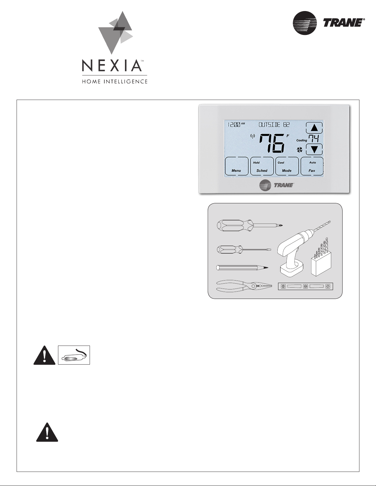
Touchscreen
Comfort Control
Model TZEMT524AA21MA
Installation Instructions and User Guide
Call (877) 288-7707 to verify compatibility.
The Trane TZEMT524 Touchscreen Comfort Control is not
compatible with the following system types:
• Radiant floor systems
• Wall heating systems
#2
1/8”
Tools Needed
Î NOTE: A 24 Volt common and hot wire
MUST be connected to the control for
operation.
MERCURY NOTICE
When this Comfort Control is replacing an old thermostat that contains mercury in a sealed tube, do not
dispose of your old thermostat in the trash. Dispose of properly. Contact your local waste management
authority for instructions regarding recycling and proper disposal of the old thermostat.
A listing of heating, ventilating and air conditioning wholesalers that participate in the Thermostat Recycling
Corporation’s recycling program are available at www.thermostat-recyle.org.
CAUTION: ELECTRICAL HAZARD
Can cause electrical shock or equipment damage. Disconnect power to heating and cooling equipment before beginning installation.

INSTALLATION GUIDE
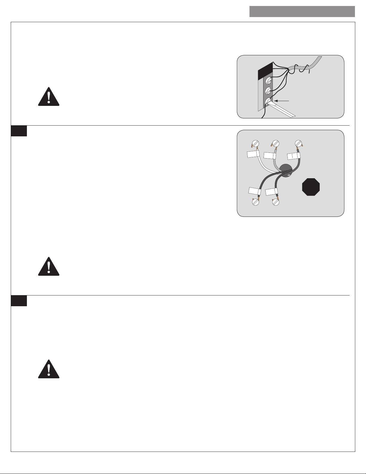
Thermostat
wire bundle
Wiring Terminals at Furnace
G
W
R
C
Unused
wires
1 Prepare for Installation
Unpack your new 524 Control and locate the 524 Control, Base Plate, mounting screws, wall anchors and wire labels.
Rc
R
R
Rc
Rh
R
R
Rh
X2 T W1 W2 W3 X Y
X2TW1W2W3XY
B C E F G O L Y1 Y2
BCEFGOLY1Y2
524 Control
Base Plate
Mounting Screws Wall Anchors Wire Labels
P516-001 Rev. 03/09-a
2 Disconnect Power at the Breaker
Located your breaker box and remove or disconnect electrical power to your HVAC system. You may need to disconnect power at
both the indoor unit and the outdoor unit.
CAUTION: ELECTRICAL HAZARD
Failure to remove power can cause electrical shock and/or equipment damage.
3 Remove your existing thermostat cover
Carefully remove the cover of your existing thermostat leaving with wires connected. Consult instructions that came with the existing
thermostat as necessary. DO NOT remove the thermostat wires yet.
4 Determine if your system has a 24V common wire connected
1. If your system is a heat pump, skip to “6 Label and remove old thermostat wires” on page 3.
2. If your existing thermostat has a terminal named C, COM, X or B* with a wire connected to it, skip to “6 Label and remove old
thermostat wires” on page 3.
* The B terminal on Trane, American Standard, Weathertron and York thermostats is the 24V Common terminal. On all other
thermostats it servers another purpose.
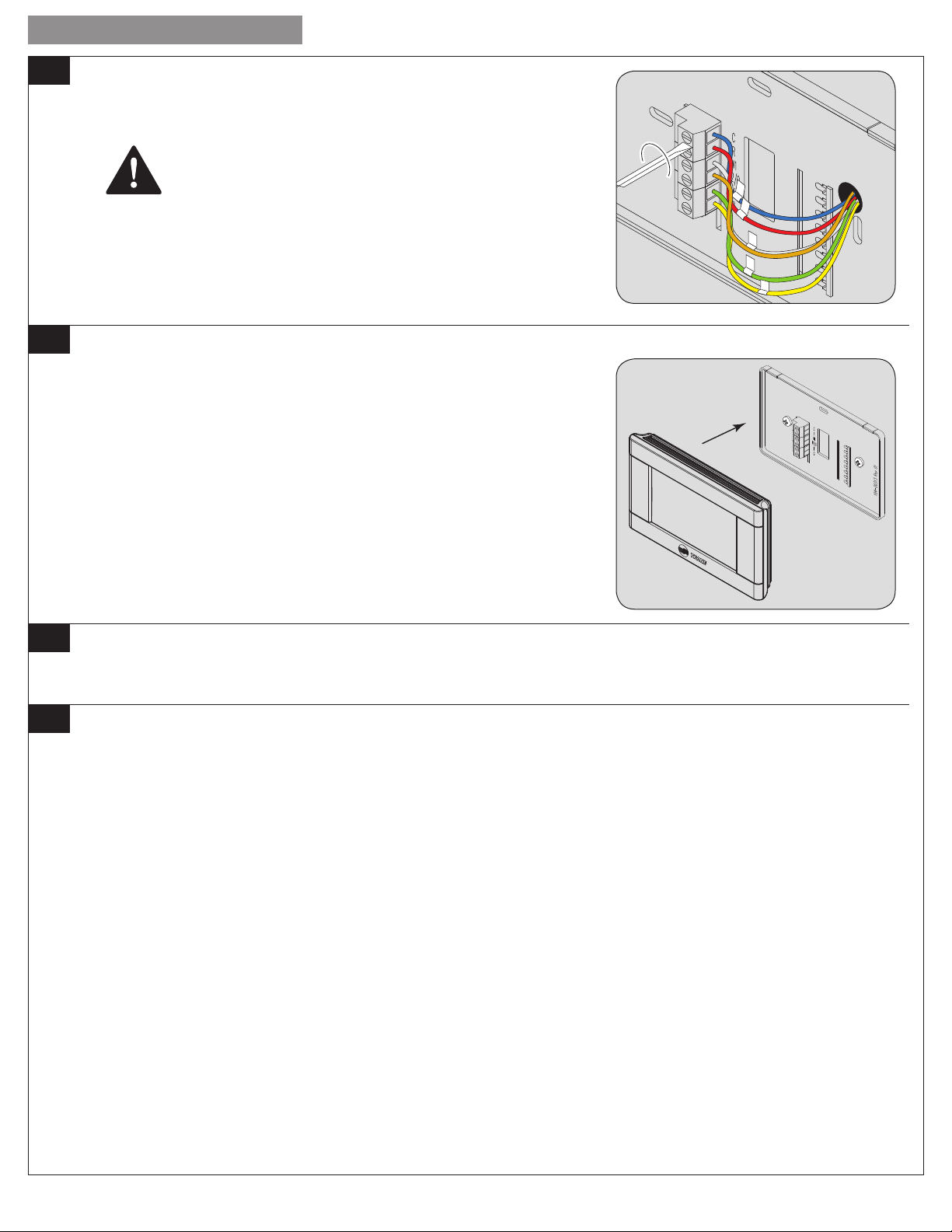
5 Connecting a 24V common wire
1. Locate all unused (disconnected) wires from the thermostat wire bundle and write
down the colors. The 24V Common wire is typically (but not always) colored blue.
2. Go to your indoor HVAC unit and remove the cover(s) to access the 24 VAC
furnace wire terminals.
3. Find the wiring terminals at the furnace and then identify the 24 VAC common
terminal identified with the letter C, X, B, or COM.
This terminal may already have a wire connected to it but it may not be a wire
that goes to the thermostat.
4. Locate the thermostat wire bundle inside the furnace panel. This wire bundle is
routed from the thermostat, through the walls, and into the furnace panel. This
bundle can be identified at the furnace by checking the wire colors connected
and not connected and comparing to the wire bundle at the thermostat.
2
Thermostat
wire bundle
Unused wires
18-HD46D1-1
INSTALLATION GUIDE
5. Find a wire from the thermostat bundle that is unused at the thermostat and at the furnace.
It is possible that one of the unused wires at the thermostat will already be connected to the 24 VAC common terminal at the
furnace. If so, go to “6 Label and remove old thermostat wires” on page 3.
6. Connect the unused wire to the 24 VAC terminal, then replace the furnace cover.
The 24 VAC common wire is typically (but not always) blue in color. If the blue
wire has been unused, it is recommended that you use the blue wire.
G
W
If you are unsure about connecting this wire or you do not have any
unused wires at the thermostat, contact Customer Service at 877-288-7707.
6 Label and remove old thermostat wires
1. Label the wires on your existing thermostat to match terminal names.
DO NOT USE WIRE COLORS TO CHOSE LABELS. THE TERMINAL NAME IS
WHAT IS IMPORTANT.
2. Locate the wiring labels included with the new thermostat.
3. Observe where each wire is connected to the existing thermostat and find the
letter shown next to that wire terminal.
4. Attach the corresponding label the wire.
IMPORTANT NOTES:
If you have a short jumper wire between two terminals, remove the jumper and
do not label it. This jumper wire is not required on the new thermostat.
If you had to connect a new 24 VAC common wire, you will use the “C” label on
that wire.
If you have a W terminal, use the W1 label on that wire.
If your thermostat has any terminals with names that do not match any on the label, write down the terminal names and wire
colors for later reference.
R
C
Y G
Y
G
W1
W1 C
Connect
wire
R
R
Rc
C
!
Wire colors and
letters may vary
TAKE A PICTURE
It is recommended that you take a picture that clearly shows the wires attached to your existing thermostat terminals. This could be
needed later if you have troubles with your installation.
7 Remove existing wall plate.
The 524 Control is designed for installation in climate controlled living spaces. It is recommended to place the unit in a central
location with good circulation. Avoid exterior walls and areas near windows, doors, vents or concealed pipes or chimneys.
NOTE: DURING THIS PROCESS, MAKE SURE THAT THE WIRES DO NOT PULL BACK INTO WALL OPENING.
5. Detach all wires from wall plate.
6. Remove all screws attaching the wall plate to the wall and remove wall plate.
7. See “MERCURY NOTICE”.
MERCURY NOTICE
When this control is replacing a control that contains mercury in a sealed tube, dispose of the old control properly. Contact
your local waste management authority for instructions regarding recycling and proper disposal. A listing of heating, ventilating
and air conditioning wholesalers that participate in the Thermostat Recycling Corporation’s recycling program are available at
www.thermostat-recyle.org .
524 Control Installation and User Guide
3
INSTALLATION GUIDE
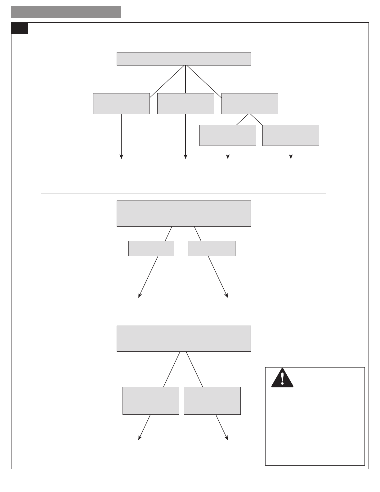
8 Identify your system type
Assuming your existing thermostat is wired correctly, these steps will help you determine what type of equipment is installed in your
home. You will use this information when you program your 524 Control.
INDOOR UNIT TYPE
You have an ELECTRIC
furnace or an
air handler
You have a
BOILER and an
air handler
Electric
Your Indoor Unit Type is:
You have a
GAS furnace
Gas Hydronic
With Fan
If you have any questions regarding your system equipment, consult a qualified HVAC professional before proceeding.
You have a
BOILER
You have a
BOILER and a radiator
or baseboard heaters
Hydronic
Without Fan
INDOOR HEAT STAGES
Observe the wires connected to your
existing thermostat and follow the decision tree.
Does NOT have
W2 wire label
Has a
W2 wire label
Your Indoor Heat Stages:
1 Stage 2 Stages
OUTDOOR UNIT TYPE
Observe the wires connected to your
existing thermostat and follow the decision tree.
Existing thermostat
does NOT have a wire
connected to the
O or (B and C) terminal
Your Outdoor Unit Type is:
4
AC
Existing thermostat
DOES have a wire
connected to the
O or (B and C) terminal
Heat
Pump
DAMAGE HAZARD
Improper system type selection can
lead to equipment damage and/
or high utility costs. Follow these
instructions to properly determine
and select the 524 Control to ensure
proper heating and cooling system
operation. If you are uncertain
about your equipment, please call a
qualified HVAC contractor.
CAUTION: EQUIPMENT
18-HD46D1-1
INSTALLATION GUIDE
Anchors
9 Prepare to install the 524 Control
1. Separate the 524 Control from the Base Plate by applying pressure to the two tabs at the top of the 524 Control.
NOTE: It is not recommended that this Z-wave™ Control be mounted onto metal structures. Metal may adversely affect the radio
frequency (RF) communication between the Control and the Z-wave™ bridge.
2. Pull the wires through the hole in the center of the 524 Control base plate.
3. Mark the position of the two mounting holes on the wall using the 524 Control
Base Plate as a template.
4. Position the new wall plate over the existing opening.
5. Mark the two holes.
6. Use a level to verify that the two hole locations are level.
7. Correct hole locations as needed.
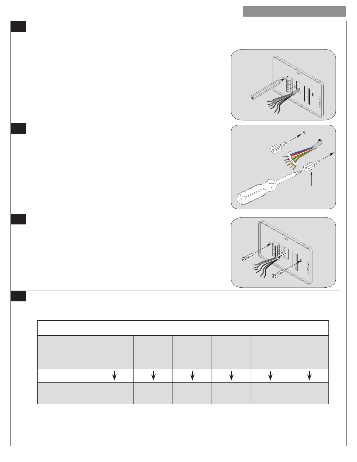
10 Prepare the mounting holes
1. Drill 1/16” pilot holes in the two locations that were marked in step 9. If mounting
to drywall with no studs behind it, enlarge pilot holes to 1/8” for anchors.
2. If using anchors, screw them into the holes.
11 Attach the new base plate to the wall
1. Pull the wires through the hole in center of wall plate.
2. Position the new wall plate over the existing opening.
3. Attach wall plate to wall using the two screws provided. Do not overtighten.
12 Review the wiring chart information
Refer the chart below to determine which wires connect to the corresponding terminal on the 524 Control.
Note than you may have more than one wire connected to a single terminal on the 524 Control.
If you have wires connected to any of these terminals,
connect it to the corresponding terminal on the 524 Control
THERMOSTAT
BEING
REPLACED
Connects to
NEW 524 CONTROL
Connect it to this
terminal on the 524
*If your existing thermostat has a “V” or “VR” wire label, connect that wire to “R” on the new thermostat, then connect the wire labeled “R” to
“W2/O/B” on the new thermostat
**On thermostats other than Trane. American Standard, Weathertron or York.
***If your existing thermostat has an independent wire connected to the RC terminal and an independent wire connected to the RH terminal, the
524 Control is incompatible with your system.
***If your existing thermostat has a wire connected to the Y2 terminal, the 524 Control is incompatible with your system.
524 Control Installation and User Guide
B
C
COM
X
C R W1 W2/O Y1 G
R
RC***
RH***
V*
VR*
AUX
E
W
W1
X2
B**
O
W2
R*
Y
Y1****
F
G
5
INSTALLATION GUIDE
13 Attach all wires securely to the 524 Control
• Note: A wire must be connected to “C” to power the thermostat.
• Use 1/8” blade screwdriver to secure wires in terminals.
CAUTION: EQUIPMENT DAMAGE HAZARD
Improper wiring can lead to equipment damage. Follow the Terminal
Connection information from “12 Review the wiring chart information”
on page 5 and carefully to ensure the control is wired properly.
After wires are secure, bare wires MUST NOT touch each other.
14 Attach the 524 Control face plate to the base plate
1. Carefully align the face plate to the wall plate while aligning pins into wire
terminals.
2. Once 524 Control face is properly aligned, apply pressure at top and bottom of
524 Control face until it is secure.
15 Turn system power back on
The 524 Control display should turn on and begin displaying information. You will now identify your system type and enter that
information into the 524 Control.
16 Programming Equipment Settings
Before your 524 Control will operate properly, you must program the equipment settings. Equipment settings are programmed from
the Service Menu.
1. From the Home Screen, press Menu. Press Next repeatedly until Service is displayed.
2. Press and hold Select until Installer Settings is displayed.
3. Press Select, Equipment Type is Displayed.
4. Press Select. Outdoor Unit Type (with the current selection) is displayed.
5. Press Select. Using the up and down arrows, navigate to the type of outdoor unit you have as you determined in “8 Identify your
system type” on page 4.
6. Press Done. Press Next. Indoor Unit Type (with the current selection) is displayed.
7. Press Select. Using the up and down arrows, navigate to the type of indoor unit you have as you determined in “8 Identify your
system type” on page 4.
8. Press Done. Press Next. Indoor Heat Stages (with the current selection) is displayed.
9. Press Select. Using the up and down arrows, navigate to the number of indoor heat stages you have as you determined in “8
Identify your system type” on page 4.
10. Press Done. If you do not have a heat pump, skip the next step.
11. Press Select. Using the up and down arrows, navigate to the setting that reflects when your heat pump’s reversing valve is
energized. Press Done.
12. Press Done. You have successfully entered your equipment type and your system should be operational.
There are many other settings in the Installer Settings section of the 524 Control that will optimize your system’s performance. The
following tables describe all of the available settings and provide a brief description of each.
WHEN YOU HAVE COMPLETED ENTERING THE INSTALLER SETTINGS, YOU WILL FURTHER CUSTOMIZE THE 524
CONTROL WITH USER SETTINGS.
6
18-HD46D1-1
 Loading...