

Trane TAM7A0C36H31SB, TAM7A0B30H21SB, TAM7A0C42H31SB, TAM7A0C60H51SB, TAM7B0C60H51SA User Manual
...Page 1
Variable Speed Modular
Multi-position
Air Handlers
2-5 Tons
TAM7A0A24H21SB
TAM7A0B30H21SB
TAM7A0C36H31SB
TAM7A0C42H31SB
TAM7A0C48H41SB
TAM7A0C60H51SB
TAM7B0C60H51SA
PUB. NO. 22-1847-03
Page 2

Features
and Benefits
• Unique cabinet design
– 2% or less air leakage
– Precision applied - durable door
seals
– Specially designed air seal around
refrigerant, condensate and
conduit connections
– Double wall foamed cabinet system
– R-4.2 Insulating Value (Avg Insulat-
ing Value R-8.2)
– No loose ber design
– Smooth cleanable interior design
– Sweat eliminating design
– Composite foamed cabinet doors
– Water proof cabinet design
– Integrated horizontal drain pans
– Modular cabinet
• Multi-position up/down ow horizontal
left/right
• Side return option (sold as accessory)
• Control board protection pocket built
into cabinet wall
• Premarked Conduit Connection
Locations
• Alert port to view control board codes
without door removal
• Alert code notication
• Low voltage terminal connection point
• Phillips head door fasteners
• Vortica® blower with polarized plug
connections and integrated slide
deck for easy removal
• Aluminum coil with integrated slide
deck for easy removal and polarized plug connections on coil EEV
• Patented enhanced coil n
• Electronic Expansion Valve (EEV) with
low ambient and low superheat
compressor protection
• Dual refrigerant compatible as shipped
• Slide in electric heaters with polarized
plug connections (sold as
accessory)
• Slide in hot water coils with polarized
plug connections (sold as
accessory)
• UVC light kit with safety switch and
polarized plug connections (sold as
accessory)
• Labeled panels and connections
• Molded in 1" standard lter rail
• Variable speed ECM motor
• Soft start fan motor operation
• Comfort RTM mode
• Built in fan delay modes
• Maximum width of 23.5"
• Compact 20.8" depth with doors
removed
• Fused 24v power
• Safety door switch
• 5 year warranty
• 10-year warranty registered
• Optional extended warranty avail-
able
© 2012 Trane
2 Pub. No. 22-1847-03
Page 3

Contents
Features and Benefits 2
Optional Equipment 4
Unique Cabinet Design Features and Benets 5
General Data 6
TAM7A0A24H21SB 6
TAM7A0B30H21SB 6
TAM7A0C36H31SB 6
TAM7A0C42H31SB 6
TAM7A0C48H41SB 6
TAM7A0C60H51SB 6
TAM7B0C60H51SA 6
Performance Data 7
Electrical Data 13
Field Wiring 20
Convertibility 24
Dimensions 25
Pub. No. 22-1847-03 3
Page 4
Optional Equipment
OPTIONAL EQUIPMENT FOR AIR HANDLERS
Accessory Number Description Fits Cabinet Size
BAYEVAC05BK1AA Electric Heater, 5kW, Breaker, RS-485 Control, 1 Ph A to C
BAYEVAC05LG1AA Electric Heater, 5kW, Lugs, RS-485 Control, 1 Ph A to C
BAYEVAC08BK1AA Electric Heater, 8kW, Breaker, RS-485 Control, 1 Ph A to C
BAYEVAC08LG1AA Electric Heater, 8kW, Lugs, RS-485 Control, 1 Ph A to C
BAYEVAC10BK1AA Electric Heater, 10kW, Breaker, RS-485 Control, 1 Ph A to C
BAYEVAC10LG1AA Electric Heater, 10kW, Lugs, RS-485 Control, 1 Ph A to C
BAYEVBC15BK1AA Electric Heater, 15kW, Breaker, RS-485 Control, 1 Ph B to C
BAYEVBC20BK1AA Electric Heater, 20kW, Breaker, RS-485 Control, 1 Ph C
BAYEVCC25BK1AA Electric Heater, 25kW, Breaker, RS-485 Control, 1 Ph C
BAYEVAC10LG3AA Electric Heater, 10kW, Lugs, RS-485 Control, 3 Ph A to C
BAYEVBC15LG3AA Electric Heater, 15kW, Lugs, RS-485 Control, 3 Ph B to C
BAYSUPFLGAA Supply Duct Flange A A
BAYSUPFLGBA Supply Duct Flange B B
BAYSUPFLGCA Supply Duct Flange C C
BAYRETFLGAA Return Duct Flange A A
BAYRETFLGB Return Duct Flange B B
BAYRETFLGCA Return Duct Flange C C
BAYSRKIT100A Side Return Kit A to C
TASB175SB Plenum Stand with integrated sound baffle A A
TASB215SB Plenum Stand with integrated sound baffle B B
TASB235SB Plenum Stand with integrated sound baffle C C
MITISRKIT01A Side Return Kit with filter A to C
BAYICSKIT01A Internal Condensate Switch Kit A to C
BAYHHKIT001A Horizontal Hanger Kit A to C
BAYUVCLK001A UVC Lights A to C
BAYLVKIT100A Low Voltage Conduit Entry Kit A to C
BAYSPEKT200A Single Power Entry Kit A to C
BAYWVAA05SC1AA Hydronic Coil - 50,000 BTUH - Slide-in with control A to A
BAYWVBB07SC1AA Hydronic Coil - 70,000 BTUH - Slide-in with control B to B
BAYWVCC08SC1AA Hydronic Coil - 80,000 BTUH - Slide-in with control C to C
BAYWACC11SC1AA Hydronic Coil - 100,000 BTUH - Add-on C to C
BAYWVBRD485A RS-485 Control for BAYWACC11SC1AA C to C
4 Pub. No. 22-1847-03
Page 5
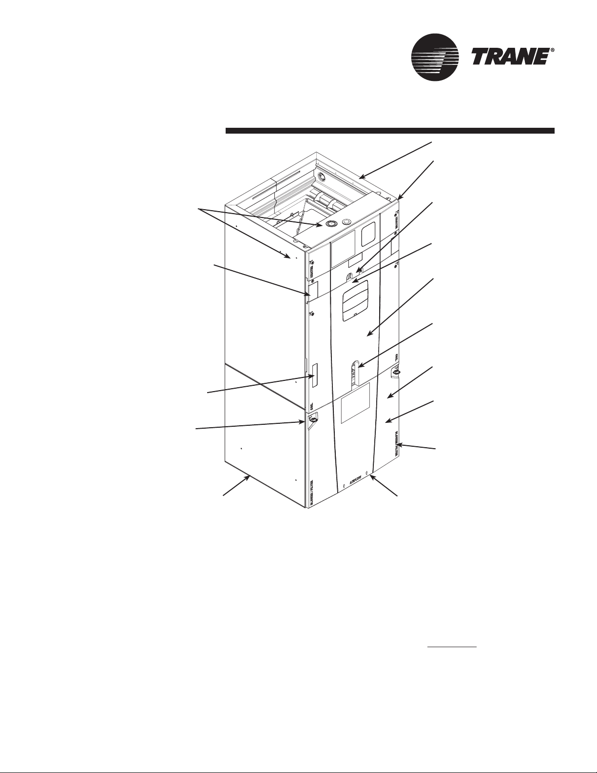
Unique Cabinet Design
Features and Benefits
1 Unique Cabinet Design
2 Precision Durable
Door Seals
5 Conduit
Connections
Locations
r Integrated Horizontal
Drain Pans
7 Alert Code Viewport
6 Tool-less Door
Fasteners
q Electronic Expansion
Valve (EEV)
3 Refrigeration
Connections
9 All Aluminum Coil
4 Condensate
Connections
t Safety Door Switch
8 VorticaTM Blower
and Deck
0 Labeled Panels
and Connections
e Compact 20.8” Depth
with Doors Removed
1 Unique Cabinet Design
- Double wall foamed cabinet system
- Waterproof Cabinet Design
- R-4.2 Insulating Value (Avg Insulating Value R-8.2)
- Composite Foamed Cabinet Doors
- Sweat Eliminating Cabinet Design
- Loose Fiber Eliminating Design
- Smooth Cleanable Cabinet Design
2 Precision Durable Door Seals
3 Refrigeration Connections
4 Condensate Connections
5 Conduit Connection Locations - Dimples or target to
mark Conduit Connection locations on Left, Right, and Top
6 Tool-less Door Fasteners
7 Alert Code Viewport
- Alert Codes can be Viewed Without Door Removal
- Control Protection Pocket
Pub. No. 22-1847-03 5
w Maximum width
is 23.5”
8 VorticaTM Blower and Deck - Polarized Plug on
Blower
9 All Aluminum Coil
- Integrated Slide Deck for Easy Removal
- Polarized Plug connections on Coil EEV
- Patented Enhanced Coil Fin
0 Labeled Panels and Connections
q Electronic Expansion Valve (EEV)
- Low Ambient and Low Superheat Protection
- Dual Refrigerant Compatible as Shipped
w Maximum width is 23.5”
e Compact 20.8” Depth with Doors Removed
r Integrated Horizontal Drain Pans
t Safety Door Switch - Fused 24V Power
y Modular Cabinet
Page 6
General
Data
MODEL TAM7A0A24H21SB
RATED VOLTS/PH/HZ. 200-230/1/60
RATINGS 1
INDOOR COIL — Type Plate Fin
Rows — F.P.I. 3 - 14
Face Area (sq. ft.) 3.67
Tube Size (in.) 3/8
Refrigerant Control EEV
Drain Conn. Size (in.) 2 3/4 NPT
DUCT CONNECTIONS
INDOOR FAN — Type Centrifugal
Diameter-Width (In.) 11 X 8
No. Used 1
Drive - No. Speeds Direct - Variable
CFM vs. in. w.g. See Fan Performance Table
No. Motors — H.P. 1 - 1/2
Motor Speed R.P.M. Variable ECM
Volts/Ph/Hz 208-230/1/60
F.L. Amps 3.0
FILTER
Filter Furnished? No
Type Recommended Throwaway
No.-Size-Thickness 1 - 16 X 20 - 1 in.
REFRIGERANT R-410A
Ref. Line Connections Brazed
Coupling or Conn. Size — in. Gas 3/4
Coupling or Conn. Size — in. Liq. 3/8
DIMENSIONS H x W x D
Crated (In.) 51-1/2 x 19 x 23-1/2
Uncrated 49-7/8 x 17-1/2 x 21-3/4
WEIGHT
Shipping (Lbs.) / Net (Lbs.) 127/116
MODEL TAM7A0C42H31SB
RATED VOLTS/PH/HZ. 200-230/1/60
RATINGS 1
INDOOR COIL — Type Plate Fin
Rows — F.P.I. 4 - 14
Face Area (sq. ft.) 5.04
Tube (in.) 3/8
Refrigerant Control EEV
Drain Conn. Size (in.) 2 3/4 NPT
DUCT CONNECTIONS
INDOOR FAN — Type Centrifugal
Diameter-Width (In.) 11 X 10
No. Used 1
Drive - No. Speeds Direct - Variable
CFM vs. in. w.g. See Fan Performance Table
No. Motors — H.P. 1 - 1/2
Motor Speed R.P.M. Variable ECM
Volts/Ph/Hz 208-230/1/60
F.L. Amps 3.0
FILTER
Filter Furnished? No
Type Recommended Throwaway
No.-Size-Thickness 1 - 22 X 20 - 1 in.
REFRIGERANT R-410A
Ref. Line Connections Brazed
Coupling or Conn. Size — in. Gas 7/8
Coupling or Conn. Size — in. Liq. 3/8
DIMENSIONS H x W x D
Crated (In.) 57-1/4 x 25-1/4 x 23-1/2
Uncrated 56-15/16 x 23-1/2 x 21-3/4
WEIGHT
Shipping (Lbs.) / Net (Lbs.) 162/151
1 These Air Handlers are AHRI. certied with various Split System Air Conditioners and Heat Pumps (AHRI STANDARD 210/240). Refer to the Split System Outdoor Unit
Product Data Guides for performance data.
2 3/4" Male Plastic Pipe (Ref.: ASTM 1785-76)
See O.D. Specications
See Outline Drawing
See O.D. Specications
See Outline Drawing
PRODUCT SPECIFICATIONS
PRODUCT SPECIFICATIONS
TAM7A0B30H21SB
200-230/1/60
See O.D. Specications
See Outline Drawing
Direct - Variable
See Fan Performance Table
Variable ECM
208-230/1/60
1 - 20 X 20 - 1 in.
56-1/2 x 23 x 23-1/2
55-11/16 x 21-5/16 x 21-3/4
TAM7A0C48H41SB
200-230/1/60
See O.D. Specications
See Outline Drawing
Direct - Variable
See Fan Performance Table
Variable ECM
208-230/1/60
Throwaway
1 - 22 X 20 - 1 in.
62-3/4 x 25-1/4 x 23-1/2
61-3/4 x 23-1/2 x 21-3/4
Plate Fin
3 - 14
5.04
3/8
EEV
3/4 NPT
Centrifugal
11 X 10
1
1 - 1/2
3.0
No
Throwaway
R-410A
Brazed
3/4
3/8
H x W x D
150/138
Plate Fin
4 - 14
5.96
3/8
EEV
3/4 NPT
Centrifugal
11 X 10
1
1 - 3/4
4.2
No
R-410A
Brazed
7/8
3/8
H x W x D
175/163
TAM7A0C36H31SB
200-230/1/60
See O.D. Specications
Plate Fin
3 - 14
5.50
3/8
EEV
3/4 NPT
See Outline Drawing
Centrifugal
11 X 10
1
Direct - Variable
See Fan Performance Table
56-15/16 x 23-1/2 x 21-3/4
TAM7A0C60H51SB,TAM7B0C60H51SA
See Fan Performance Table
61-11/16 x 23-1/2 x 21-3/4
1 - 1/2
Variable ECM
208-230/1/60
3.0
No
Throwaway
1 - 22 X 20 - 1 in.
R-410A
Brazed
7/8
3/8
H x W x D
57-1/4 x 25-1/4 x 23-1/2
157/146
200-230/1/60
See O.D. Specications
Plate Fin
4 - 14
5.96
3/8
EEV
3/4 NPT
See Outline Drawing
Centrifugal
11 X 10
1
Direct - Variable
1 - 1
Variable ECM
208-230/1/60
5.5
No
Throwaway
1 - 22 X 20 - 1 in.
R-410A
Brazed
7/8
3/8
H x W x D
62-3/4 x 25-1/4 x 23-1/2
175/163
6 Pub. No. 22-1847-03
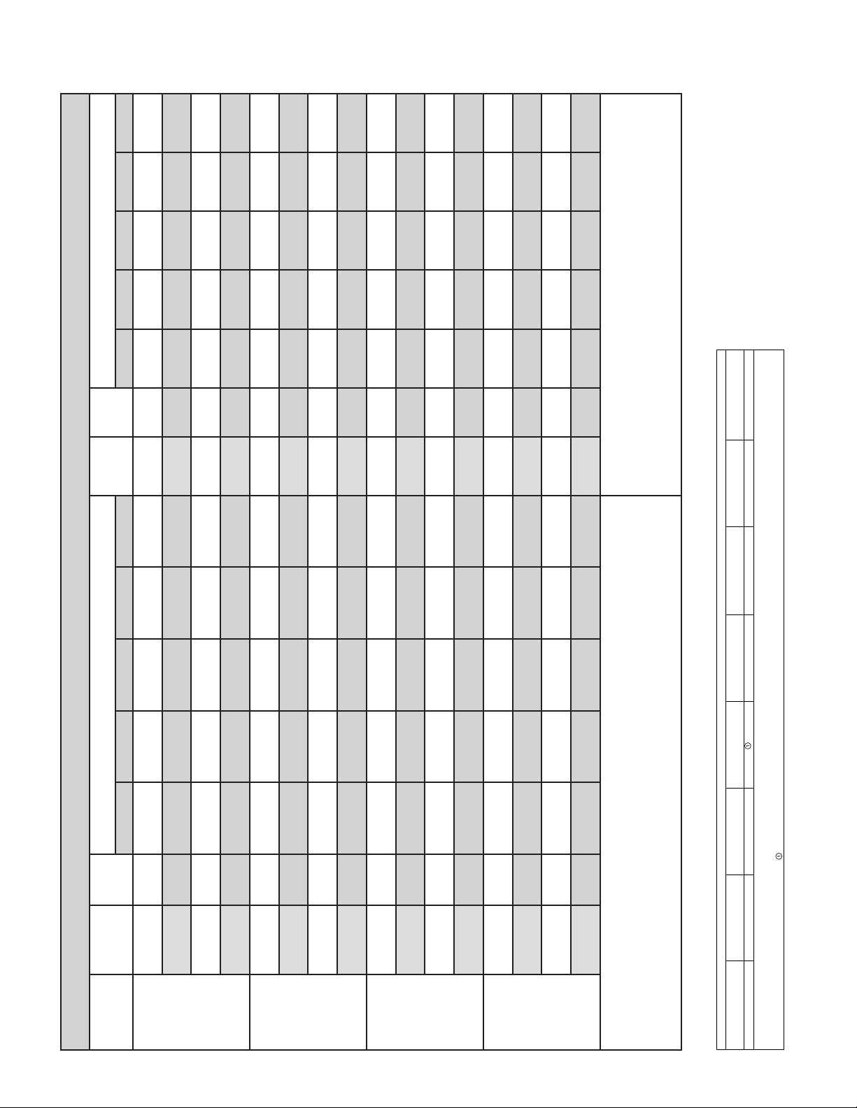
Page 7
595
A
A
A
A
A
A
A
A
A
B
X
192
599
153
600
115
80
599
EXTERNAL STATIC PRESSURE
46
586
CFM
Watts
Powe r
Airow
390
HEATING
AIRFLOW
CFM/ton
SETTING
629
202
637
163
636
124
88
633
53
618
CFM
Watts
410
CFM/ton
660
212
672
174
669
134
96
665
59
650
CFM
Watts
430
CFM/ton
696
225
704
185
703
144
696
104
66
681
CFM
Watts
450
CFM/ton
802
268
811
227
809
182
800
137
94
780
CFM
Watts
390
CFM/ton
842
287
851
244
848
198
838
151
818
106
CFM
Watts
410
CFM/ton
881
307
889
262
887
215
876
167
856
119
CFM
Watts
430
CFM/ton
920
327
927
282
925
233
913
183
894
134
CFM
Watts
450
CFM/ton
992
370
322
1000
997
271
986
218
964
164
CFM
Watts
390
CFM/ton
400
1040
353
1049
299
1045
244
1034
188
1013
CFM
Watts
410
CFM/ton
434
1089
385
1097
331
1095
273
1083
214
1063
CFM
Watts
430
CFM/ton
469
1135
420
1145
365
1145
305
1135
243
1114
CFM
Watts
450
CFM/ton
486
1157
453
1189
397
1190
337
1181
272
1160
CFM
Watts
390
CFM/ton
477
1146
486
1230
444
1249
384
1244
317
1225
CFM
Watts
410
CFM/ton
468
1135
476
1217
486
1298
434
1305
368
1291
CFM
Watts
430
CFM/ton
460
1124
467
1206
475
1285
485
1361
422
1355
CFM
Watts
450
CFM/ton
water column.
3. Torque mode will reduce airow when static is above approximately 0.3"
4. All heating modes default to Constant CFM
5. Cooling airow values are with wet coil, no lter
BAYEVBC20BK1A
BAYEVBC15BK1A
541 / NA
175 / NA
581 / NA
185 / NA
618 / NA
196 / NA
653 / NA
207 / NA
748 / 428
242 / 153
788 / 500
259 / 168
827 / 561
276 / 183
866 / 615
294 / 199
923 / 709
324 / 232
971 / 766
351 / 255
380 / 280
411 / 307
431 / 325
472 / 364
483 / 408
1019 / 821
1066 / 877
1095 / 910
1151 / 978
1164 / 1046
547 / NA
TAM7A0A24 AIRFLOW PERFORMANCE
548 / 407
148 / 94
137 / NA
588 / 167
101 / 78
110 / 87
587 / 464
625 / 325
158 / 101
660 / 406
119 / 96
624 / 513
659 / 556
168 / 112
756 / 563
201 / 144
128 / 105
754 / 666
158 / 133
796 / 617
216 / 159
835 / 666
793 / 710
172 / 146
832 / 751
873 /712
233 / 174
250 / 189
187 / 161
870 / 792
203 / 175
930 / 796
278 / 222
978 / 849
927 / 869
229 / 207
974 / 918
304 / 244
332 / 270
1026 / 901
253 / 230
279 / 255
1022 / 967
362 / 297
1074 / 953
1071 / 1018
382 / 315
1103 / 985
308 / 282
327 / 301
1101 / 1048
423 / 355
1161 / 1050
1218 / 1115
367 / 341
1160 / 1111
1220 / 1175
CONSTANT CFM MODE / CONSTANT TORQUE MODE
EXTERNAL STATIC PRESSURE
Airow
AIRFLOW
COOLING
547 / 559
0.1 0.3 0.5 0.7 0.9 0.1 0.3 0.5 0.7 0.9
542 / 652
CFM
Powe r
360
SETTING
67 / 71
75 / 78
583 / 593
38 / 59
43 / 65
574 / 679
CFM
Watts
Watts
380
CFM/ton
CFM/ton
82 / 85
618 / 626
651 / 658
49 / 71
605 / 705
636 / 731
CFM
CFM
Watts
400
420
CFM/ton
90 / 93
743 / 746
115 / 118
55 / 78
75 / 101
723 / 809
CFM
Watts
Watts
360
CFM/ton
CFM/ton
782 / 784
128 / 131
820 / 821
86 / 113
761 / 843
799 / 877
CFM
CFM
Watts
380
400 †
CFM/ton
141 / 144
858 / 858
155 / 158
97 / 125
836 / 911
109 / 139
CFM
Watts
Watts
420
CFM/ton
CFM/ton
914 / 930
179 / 189
962 / 976
892 / 979
130 / 168
939 / 1024
CFM
CFM
Watts
360
380
CFM/ton
201 / 211
225 / 236
1009 / 1023
149 / 190
170 / 215
986 / 1070
CFM
Watts
Watts
400
CFM/ton
CFM/ton
251 / 264
1058 / 1072
1035 / 1118
CFM
420
269 / 282
1088 / 1102
194 / 242
209 / 261
1065 / 1148
CFM
Watts
Watts
360
CFM/ton
CFM/ton
307 / 322
1149 / 1164
1211 / 1227
244 / 301
1126 / 1209
1190 / 1271
CFM
CFM
Watts
380
400
CFM/ton
475 / 455
1151 / 1113
467 / 399
483 / 448
1237 / 1180
412 / 386
459 / 435
1278 / 1239
350 / 368
397 / 418
1273 / 1289
285 / 347
331 / 397
1255 / 1334
CFM
Watts
Watts
420
CFM/ton
CFM/ton
600/713 -- -- --
BAYEVAC10LG3AA BAYEVCB15LG3A
/900
WITHOUT HEAT PUMP / WITH HP
675 1
BAYEVAC10LG1A
BAYEVAC10BK1A
MINIMUM HEATER AIRFLOW CFM - HEATER MATRI
SEE AIR HANDLER NAMEPLATE FOR APPROVED COMBINATIONS
Heater not qualified for 208V when installed in horizontal left position without Heat Pump
1
BAYEVAC08LG1A
BAYEVAC08BK1A
638/713 638/900
BAYEVAC05LG1A
BAYEVAC05BK1A
(TONS)
OUTDOOR
MULTIPLIER
Pub. No. 22-1847-03 7
1.5 tons
2 tons †
2.5 tons
3 tons
NOTES:
1. † Factory Setting
2. Status LED will blink once per 100 CFM requested. In torque mode, actual airow may be lower.
MODEL NO.
TAM7A0A24H21S
Minimum Heating Airow Settings
NOTE: Minimum auxiliary heating airow is automatically congured by the air handler model and
the auxiliary heater model number. This is not eld adjustable.
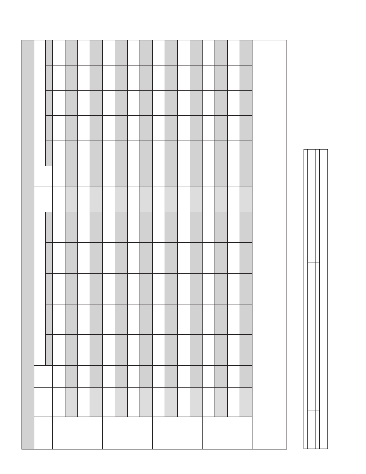
Page 8
540
A
A
A
B
8
0
0
8
3
5
X
161
566
128
96
588
65
609
EXTERNAL STATIC PRESSURE
35
630
CFM
Watts
Powe r
Airow
390
HEATING
AIRFLOW
CFM/ton
SETTING
578
169
601
136
621
102
70
639
38
657
CFM
Watts
410
CFM/ton
614
177
636
143
653
109
75
669
42
683
CFM
Watts
430
CFM/ton
649
186
669
151
685
115
80
698
45
709
CFM
Watts
450
CFM/ton
766
219
781
180
791
139
99
797
60
800
CFM
Watts
390
CFM/ton
810
233
822
192
830
150
834
107
66
834
CFM
Watts
410
CFM/ton
853
248
864
205
869
161
871
116
73
868
CFM
Watts
430
CFM/ton
895
263
905
219
908
172
908
126
80
902
CFM
Watts
450
CFM/ton
974
295
982
247
982
196
977
145
95
967
CFM
Watts
390
CFM/ton
318
1027
268
1034
214
1033
160
1025
106
1012
CFM
Watts
410
CFM/ton
342
1078
290
1087
234
1084
176
1074
119
1057
CFM
Watts
430
CFM/ton
366
1128
314
1139
255
1136
194
1124
133
1104
CFM
Watts
450
CFM/ton
389
1170
336
1185
276
1184
211
1170
147
1147
CFM
Watts
390
CFM/ton
418
1223
367
1245
306
1247
238
1233
168
1208
CFM
Watts
410
CFM/ton
446
1271
398
1300
337
1309
267
1298
193
1271
CFM
Watts
430
CFM/ton
472
1314
427
1350
369
1368
299
1363
221
1338
CFM
Watts
450
CFM/ton
0.35" water column.
3. Torque mode will reduce airow when static is above approximately
4. All heating modes default to Constant CFM
5. Cooling airow values are with wet coil, no lter
--
BAYEVBC20BK1AA
850/110
482 / NA
150 / NA
524 / NA
158 / NA
562 / NA
166 / NA
581 / NA
170 / NA
704 / NA
200 / NA
748 / NA
213 / NA
792 / NA
227 / NA
813 / 180
234 / 132
898 / 454
264 / 148
951 / 538
285 / 163
307 / 180
318 / 189
344 / 210
374 / 236
403 / 265
417 / 281
1224 / 931
351 / 263
306 / 279
1245 / 1055
290 / 252
305 / 267
1247 / 1162
765/106
BAYEVCB15LG3AA BAYEVBC15BK1AA
680/80
BAYEVAC10LG3AA
509 / NA
118 / NA
547 / NA
TAM7A0B30 AIRFLOW PERFORMANCE
87 / 63
533 / 299
569 / 359
125 / NA
584 / NA
132 / NA
93 / 68
99 / 73
604 / 410
602 / NA
136 / NA
719 / 344
102 / 76
620 / 434
731 / 575
163 / 99
762 / 419
174 / 107
125 / 96
771 / 622
134 / 104
803 / 484
186 / 117
824 / 513
811 / 667
144 / 113
831 / 689
192 / 122
907 / 658
219 / 150
150 / 118
909 / 804
172 / 144
1003 / 614
958 / 718
237 / 165
1010 / 779
959 / 856
188 / 158
1009 / 908
1029 / 650
257 / 182
268 / 190
1036 / 808
205 / 174
214 / 182
1034 / 934
1085 / 727
1444 / 809
292 / 211
1094 / 873
1156 / 945
236 / 201
1091 / 993
1153 / 1059
1198 / 890
321 / 235
1216 / 1018
262 / 225
1216 / 1127
CONSTANT CFM MODE / CONSTANT TORQUE MODE
EXTERNAL STATIC PRESSURE
Airow
AIRFLOW
COOLING
560 / 538
0.1 0.3 0.5 0.7 0.9 0.1 0.3 0.5 0.7 0.9
591 / 685
CFM
Powe r
360
SETTING
58 / 56
62 / 60
593 / 572
30 / 41
33 / 45
618 / 711
CFM
Watts
Watts
380
CFM/ton
CFM/ton
67 / 65
624 / 605
639 / 621
37 / 49
645 / 738
659 / 751
CFM
CFM
Watts
400
420
CFM/ton
69 / 67
87 / 85
741 / 726
38 / 50
51 / 66
750 / 840
CFM
Watts
Watts
360
CFM/ton
CFM/ton
95 / 92
779 / 764
816 / 802
57 / 72
784 / 874
818 / 908
CFM
CFM
Watts
380
400 †
CFM/ton
103 / 100
834 / 820
107 / 104
62 / 79
66 / 83
835 / 924
CFM
Watts
Watts
420
CFM/ton
CFM/ton
908 / 921
125 / 129
955 / 968
80 / 105
904 / 1017
947 / 1061
CFM
CFM
Watts
360
380
CFM/ton
138 / 142
152 / 156
1002 / 1016
89 / 117
100 / 131
991 / 1106
CFM
Watts
Watts
400
CFM/ton
CFM/ton
159 / 164
1026 / 1040
1013 / 1129
CFM
420
177 / 182
1080 / 1095
106 / 138
120 / 156
1063 / 1182
CFM
Watts
Watts
360
CFM/ton
CFM/ton
199 / 205
1140 / 1157
1120 / 1241
CFM
380
224 / 231
1202 / 1221
137 / 178
157 / 203
1179 / 1304
CFM
Watts
Watts
400
CFM/ton
CFM/ton
237 / 246
1233 / 1255
168 / 217
1210 / 1337
CFM
Watts
420
CFM/ton
WITHOUT HEAT PUMP / WITH HP
765/102
BAYEVAC10LG1AA
BAYEVAC10BK1A
MINIMUM HEATER AIRFLOW CFM - HEATER MATRI
SEE AIR HANDLER NAMEPLATE FOR APPROVED COMBINATIONS
723/102
BAYEVAC08LG1AA
BAYEVAC08BK1A
723/80
BAYEVAC05LG1AA
BAYEVAC05BK1A
(TONS)
OUTDOOR
MULTIPLIER
8 Pub. No. 22-1847-03
1.5 tons
2 tons †
2.5 tons
3 tons
NOTES:
1. † Factory Setting
2. Status LED will blink once per 100 CFM requested. In torque mode, actual airow may be lower.
MODEL NO.
TAM7A0B30H21S
Minimum Heating Airow Settings
NOTE: Minimum auxiliary heating airow is automatically congured by the air handler model and
the auxiliary heater model number. This is not eld adjustable.
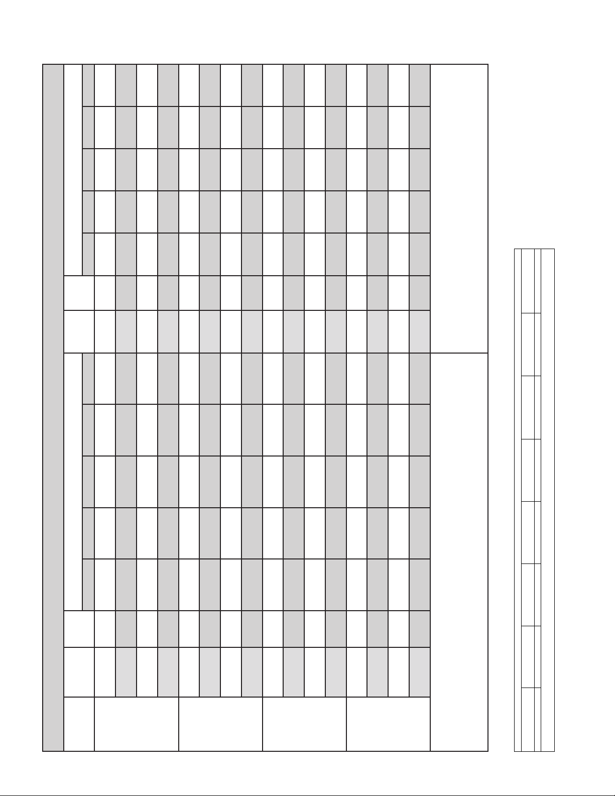
Page 9
806
A
A
A
A
A
A
A
A
A
B
9
6
6
9
8
9
2
X
215
849
799
174
841
794
133
835
94
797
837
EXTERNAL STATIC PRESSURE
57
813
849
228
185
142
102
63
891
883
876
876
884
242
197
153
110
69
912
902
897
895
902
249
203
158
114
72
287
1014
237
1005
998
188
991
138
91
992
307
1064
256
1057
204
1048
152
1040
101
1036
1116
1110
1099
1089
1081
330
277
221
167
113
341
1141
287
1136
231
1125
174
1113
119
1105
377
1215
321
1214
261
1203
200
1189
140
1175
406
1272
351
1275
288
1267
223
1251
159
1234
435
1325
381
1335
318
1331
250
1315
180
1295
449
1350
396
1364
264
1362
264
1348
192
1327
1389
1409
1414
1403
1380
472
422
360
289
214
476
1395
456
1467
397
1481
327
1478
248
1459
472
1388
478
1504
433
1542
366
1550
287
1538
470
1385
477
1501
450
1570
385
1583
307
1575
CFM
CFM
Watts
Powe r
Airow
400
420
HEATING
AIRFLOW
TAM7A0C36 AIRFLOW PERFORMANCE
CFM/ton
SETTING
698 / 19
185 / 163
148 / 90
695 / 297
111 / 85
694 / 530
742 / 84
740 / 387
738 / 585
CONSTANT CFM MODE / CONSTANT TORQUE MODE
EXTERNAL STATIC PRESSURE
77 / 77
704 / 706
744 / 747
CFM
Watts
Watts
440
CFM/ton
CFM/ton
197 / 135
786 / 213
209 / 120
158 / 98
783 / 460
169 / 107
120 / 93
780 / 635
129 / 102
84 / 84
91 / 91
784 / 787
CFM
CFM
Watts
450
400
CFM/ton
827 / 329
222 / 123
884 / 488
824 / 524
180 / 117
881 / 639
822 / 683
139 / 111
877 / 776
99 / 99
823 / 826
876 / 905
CFM
Watts
Watts
420
CFM/ton
CFM/ton
240 / 143
936 / 565
258 / 157
197 / 138
932 / 702
213 / 151
153 / 130
927 / 830
167 / 142
110 / 116
924 / 952
121 / 127
CFM
CFM
Watts
440
450
CFM/ton
987 / 634
277 / 172
1039 / 700
983 / 762
230 / 166
1034 / 820
977 / 883
181 / 155
1028 / 935
971 / 999
133 / 139
1020 / 1047
CFM
Watts
Watts
400
CFM/ton
CFM/ton
298 / 187
308 / 196
1064 / 731
248 / 181
257 / 189
1060 / 848
197 / 170
206 / 177
1053 / 961
146 / 153
153 / 160
1044 / 1070
CFM
CFM
Watts
Watts
420
440
CFM/ton
CFM/ton
334 / 217
1123 / 805
1122 / 916
1114 / 1024
1102 / 1129
363 / 240
1184 / 877
282 / 209
309 / 231
1184 / 984
227 / 196
251 / 218
1176 / 1087
171 / 178
191 / 198
1161 / 1188
CFM
CFM
Watts
Watts
450
400
CFM/ton
CFM/ton
391 / 264
389 / 262
1242 / 948
1237 / 942
337 / 256
335 / 254
1246 / 1051
1241 / 1046
277 / 241
274 / 239
1238 / 1152
1233 / 1146
213 / 221
211 / 219
1223 / 1249
1218 / 1244
CFM
CFM
Watts
Watts
420
440
CFM/ton
CFM/ton
423 / 294
1300 / 1025
1311 / 1126
1307 / 1223
1291 / 1317
456 / 329
1358 / 1108
370 / 285
405 / 320
1378 / 1206
307 / 270
343 / 304
1380 / 1301
240 / 249
273 / 282
1367 / 1393
CFM
Watts
450
3. Torque mode will reduce airow when static is above approximately
CFM/ton
478 / 367
1394 / 1189
440 / 357
1438 / 1286
380 / 341
1449 / 1379
309 / 319
1442 / 1468
0.35" water column.
4. All heating modes default to Constant CFM
5. Cooling airow values are with wet coil, no lter
1236/144
BAYEVBC20BK1A
1030/133
BAYEVBC15BK1A
927/128
824/97
BAYEVAC10LG3AA BAYEVCB15LG3A
WITHOUT HEAT PUMP / WITH HP
927/123
BAYEVAC10LG1A
BAYEVAC10BK1A
MINIMUM HEATER AIRFLOW CFM - HEATER MATRI
0.1 0.3 0.5 0.7 0.9 0.1 0.3 0.5 0.7 0.9
44 / 63
49 / 69
54 / 75
60 / 82
68 / 97
77 / 107
86 / 118
724 / 858
759 / 892
795 / 924
830 / 957
879 / 1026
923 / 1067
968 / 1110
CFM
CFM
CFM
CFM
CFM
CFM
Watts
Watts
Watts
Watts
Powe r
Airow
350
370
390
CFM/ton
SETTING
AIRFLOW
COOLING
(TONS)
OUTDOOR
MULTIPLIER
Pub. No. 22-1847-03 9
CFM/ton
410
CFM/ton
2 tons
Watts
350
CFM/ton
CFM/ton
Watts
370
CFM/ton
CFM
390
2.5 tons
96 / 130
1012 / 1153
CFM
Watts
Watts
410
CFM/ton
CFM/ton
102 / 137
116 / 154
1036 / 1175
1090 / 1229
CFM
CFM
Watts
Watts
350
370 †
CFM/ton
CFM/ton
132 / 173
1145 / 1285
CFM
Watts
390
CFM/ton
3 tons †
150 / 195
149 / 193
1204 / 1343
1199 / 1338
CFM
CFM
Watts
Watts
410
350
CFM/ton
CFM/ton
172 / 222
1269 / 1408
CFM
370
200 / 255
1342 / 1481
CFM
Watts
Watts
390
CFM/ton
CFM/ton
3.5 tons
232 / 291
1419 / 1555
CFM
Watts
410
CFM/ton
NOTES:
1. † Factory Setting
2. Status LED will blink once per 100 CFM requested. In torque mode, actual airow may be lower.
Minimum Heating Airow Settings
SEE AIR HANDLER NAMEPLATE FOR APPROVED COMBINATIONS
876/123
BAYEVAC08LG1A
BAYEVAC08BK1A
876/97
BAYEVAC05LG1A
BAYEVAC05BK1A
MODEL NO.
TAM7A0C36H31S
NOTE: Minimum auxiliary heating airow is automatically congured by the air handler model and
the auxiliary heater model number. This is not eld adjustable.
Page 10

901
A
A
A
A
A
A
A
A
A
B
3
0
0
3
8
5
0
X
264
951
895
217
946
893
170
943
897
125
945
EXTERNAL STATIC PRESSURE
82
912
956
283
234
185
137
92
304
1002
997
253
992
201
992
151
102
1000
325
1052
273
1047
219
1042
166
1040
114
1044
339
1082
285
1078
230
1072
175
1069
122
1071
368
1142
312
1139
254
1132
195
1127
138
1126
1201
1200
1193
1186
1181
399
341
280
218
157
432
1259
373
1261
309
1256
243
1247
177
1239
432
1259
373
1261
309
1256
243
1247
177
1239
470
1323
412
1331
346
1329
276
1319
205
1308
475
1332
452
1398
386
1401
313
1394
237
1381
470
1323
481
1443
429
1471
355
1468
275
1456
472
1326
475
1434
410
1441
337
1436
258
1423
466
1317
477
1436
459
1517
386
1520
304
1511
461
1308
470
1426
472
1536
437
1599
356
1598
456
1301
464
1417
471
1534
451
1620
409
1679
CFM
CFM
Watts
Powe r
Airow
360
380
HEATING
AIRFLOW
TAM7A0C42 AIRFLOW PERFORMANCE
CFM/ton
SETTING
813 / 208
232 / 143
815 / 523
191 / 128
820 / 712
149 / 125
866 / 353
867 / 597
870 / 768
CONSTANT CFM MODE / CONSTANT TORQUE MODE
EXTERNAL STATIC PRESSURE
832 / 861
108 / 114
880 / 909
CFM
Watts
Watts
400
CFM/ton
CFM/ton
250 / 144
918 / 458
268 / 155
162 / 141
918 / 665
222 / 155
162 / 137
920 / 823
176 / 151
119 / 126
926 / 956
130 / 139
CFM
CFM
Watts
420
360
CFM/ton
969 / 546
288 / 169
983 / 570
968 / 729
240 / 170
984 / 748
969 / 877
191 / 165
984 / 892
143 / 152
973 / 1003
987 / 1017
CFM
Watts
Watts
380
CFM/ton
CFM/ton
294 / 174
320 / 194
1045 / 662
246 / 175
269 / 196
1045 / 821
196 / 170
217 / 189
1044 / 956
147 / 156
164 / 174
1043 / 1074
CFM
CFM
Watts
Watts
400
420
CFM/ton
CFM/ton
348 / 217
1107 / 747
1106 / 893
1103 / 1019
1100 / 1132
379 / 242
1168 / 828
294 / 218
322 / 242
1167 / 964
239 / 210
264 / 234
1164 / 1083
183 / 195
203 / 217
1159 / 1190
CFM
CFM
Watts
Watts
360
380
CFM/ton
CFM/ton
370 / 236
1152 / 808
1152 / 946
1148 / 1067
1143 / 1175
407 / 268
1222 / 901
315 / 236
350 / 267
1224 / 1028
257 / 228
288 / 257
1220 / 1142
198 / 211
224 / 239
1212 / 1245
CFM
CFM
Watts
Watts
400
420
CFM/ton
CFM/ton
445 / 303
1289 / 991
1295 / 1110
1293 / 1218
1283 / 1317
479 / 343
1345 / 1080
387 / 301
427 / 340
1364 / 1192
323 / 291
361 / 328
1366 / 1295
254 / 272
289 / 308
1357 / 1390
CFM
CFM
Watts
Watts
360
380
CFM/ton
CFM/ton
459 / 330
1313 / 1053
1321 / 1167
1318 / 1272
1309 / 1368
477 / 378
1339 / 1153
401 / 327
447 / 374
1398 / 1260
336 / 316
381 / 361
1401 / 1360
266 / 296
307 / 340
1394 / 1542
CFM
CFM
Watts
Watts
400
420
CFM/ton
CFM/ton
470 / 429
1327 / 1248
1451 / 1350
1481 / 1445
1479 / 1534
465 / 481
1315 / 1333
482 / 425
475 / 476
1438 / 1432
428 / 411
470 / 462
1544 / 1525
354 / 389
403 / 439
1561 / 1611
0.35" water column.
3. Torque mode will reduce airow when static is above approximately
4. All heating modes default to Constant CFM
5. Cooling airow values are with wet coil, no lter
1380/161
BAYEVBC20BK1A
1150/149
BAYEVBC15BK1A
1035/143
920/109
BAYEVAC10LG3AA BAYEVCB15LG3A
WITHOUT HEAT PUMP / WITH HP
1035/138
BAYEVAC10LG1A
BAYEVAC10BK1A
MINIMUM HEATER AIRFLOW CFM - HEATER MATRI
0.1 0.3 0.5 0.7 0.9 0.1 0.3 0.5 0.7 0.9
68 / 96
76 / 107
85 / 118
95 / 131
853 / 988
896 / 1030
939 / 1072
983 / 1115
CFM
CFM
CFM
Watts
Powe r
Airow
330
SETTING
AIRFLOW
COOLING
(TONS)
OUTDOOR
10 Pub. No. 22-1847-03
MULTIPLIER
Watts
350
CFM/ton
CFM/ton
Watts
370
CFM/ton
2.5 tons
CFM
390
99 / 135
996 / 1128
CFM
Watts
Watts
330
CFM/ton
CFM/ton
112 / 152
1049 / 1180
CFM
350
127 / 171
1101 / 1233
CFM
Watts
Watts
370
CFM/ton
CFM/ton
3 tons
144 / 192
1156 / 1288
CFM
390
140 / 187
1142 / 1274
CFM
Watts
Watts
330
CFM/ton
CFM/ton
162 / 214
1208 / 1340
CFM
350
187 / 245
1274 / 1408
CFM
Watts
Watts
370 †
CFM/ton
CFM/ton
3.5 tons †
215 / 280
196 / 268
1344 / 1479
1299 / 1457
CFM
CFM
Watts
Watts
390
330
CFM/ton
CFM/ton
232 / 312
1380 / 1538
CFM
350
273 / 359
1466 / 1618
CFM
Watts
Watts
370
CFM/ton
CFM/ton
4 tons
320 / 409
1553 / 1693
CFM
Watts
390
CFM/ton
NOTES:
1. † Factory Setting
2. Status LED will blink once per 100 CFM requested. In torque mode, actual airow may be lower.
Minimum Heating Airow Settings
SEE AIR HANDLER NAMEPLATE FOR APPROVED COMBINATIONS
978/138
BAYEVAC08LG1A
BAYEVAC08BK1A
978/109
BAYEVAC05LG1A
BAYEVAC05BK1A
MODEL NO.
TAM7A0C42H31S
NOTE: Minimum auxiliary heating airow is automatically congured by the air handler model and
the auxiliary heater model number. This is not eld adjustable.
Page 11

330
A
A
A
X
1141
286
1150
237
1154
184
1155
EXTERNAL STATIC PRESSURE
128
1150
CFM
Watts
Powe r
Airow
380
HEATING
AIRFLOW
CFM/ton
SETTING
356
1199
310
1207
259
1210
203
1210
145
1204
CFM
Watts
400
CFM/ton
384
1258
335
1264
282
1267
224
1266
162
1259
CFM
Watts
420
CFM/ton
413
1316
363
1322
307
1324
246
1322
182
1314
CFM
Watts
440
CFM/ton
418
1325
368
1331
250
1333
250
1331
185
1323
CFM
Watts
380
CFM/ton
457
1395
403
1399
343
1400
279
1398
211
1388
CFM
Watts
400
CFM/ton
497
1463
441
1469
379
1468
312
1465
240
1455
CFM
Watts
420
CFM/ton
542
1534
483
1538
418
1538
347
1534
272
1523
CFM
Watts
440
CFM/ton
529
1514
471
1518
406
1518
337
1514
262
1502
CFM
Watts
380
CFM/ton
581
1591
522
1598
454
1598
382
1594
302
1582
CFM
Watts
400
CFM/ton
638
1669
577
1678
508
1680
421
1675
348
1664
CFM
Watts
420
CFM/ton
668
1708
634
1755
565
1760
486
1758
400
1748
CFM
Watts
440
CFM/ton
659
1697
598
1707
528
1710
451
1706
367
1695
CFM
Watts
380
CFM/ton
661
1700
664
1792
594
1799
515
1799
428
1790
CFM
Watts
400
CFM/ton
648
1683
656
1783
662
1884
584
1889
496
1885
CFM
Watts
420
CFM/ton
636
1667
643
1765
652
1871
655
1973
568
1976
CFM
Watts
440
CFM/ton
water column.
3. Torque mode will reduce airow when static is above approximately 0.4"
4. All heating modes default to Constant CFM
5. Cooling airow values are with wet coil, no lter
6. ** Not an actual OD size.
994 / 654
270 / 174
292 / 194
315 / 215
341 / 238
334 / 232
365 / 259
399 / 288
435 / 320
412 / 308
455 / 346
502 / 388
553 / 434
505 / 391
563 / 444
625 / 503
1053 / 738
232 / 173
1006 / 786
1065 / 859
TAM7A0C48 AIRFLOW PERFORMANCE
190 / 163
1015 / 907
1072 / 972
1112 / 816
252 / 192
274 / 212
1122 / 929
208 / 180
227 / 199
1128 / 1035
1170 / 890
1156 / 872
297 / 233
1180 / 996
1185 / 1097
291 / 227
1165 / 980
248 / 219
242 / 214
1171 / 1082
1224 / 955
1292 / 1036
319 / 253
1232 / 1056
1236 / 1153
350 / 281
1299 / 1132
268 / 238
296 / 265
1302 / 1224
1361 / 1115
1316 / 1088
384 / 312
1367 / 1207
1369 / 1295
362 / 301
1323 / 1181
327 / 295
307 / 284
1326 / 1271
1395 / 1177
1475 / 1267
402 / 338
1401 / 1266
1403 / 1352
446 / 379
1480 / 1352
343 / 321
384 / 361
1481 / 1435
1554 / 1356
1480 / 1272
495 / 425
449 / 382
1560 / 1439
1485 / 1357
430 / 406
387 / 364
1560 / 1519
1486 / 1440
1568 / 1373
1655 / 1475
505 / 434
1575 / 1455
1664 / 1554
439 / 415
1575 / 1535
1666 / 1632
666 / 567
1708 / 1576
565 / 493
630 / 558
1751 / 1653
497 / 474
561 / 539
1756 / 1728
CONSTANT CFM MODE / CONSTANT TORQUE MODE
EXTERNAL STATIC PRESSURE
143 / 143
158 / 160
175 / 177
194 / 196
189 / 191
212 / 215
237 / 241
265 / 270
247 / 260
280 / 295
317 / 335
359 / 380
319 / 337
367 / 389
422 / 447
1017 / 1020
1073 / 1078
1129 / 1136
1185 / 1194
1171 / 1179
1235 / 1246
1300 / 1313
1366 / 1381
1324 / 1358
1399 / 1436
1476 / 1516
1555 / 1597
1481 / 1521
1570 / 1613
1661 / 1707
483 / 512
1754 / 1801
0.1 0.3 0.5 0.7 0.9 0.1 0.3 0.5 0.7 0.9
92 / 117
106 / 132
120 / 149
136 / 167
132 / 162
152 / 185
174 / 210
198 / 238
212 / 228
212 / 262
245 / 301
283 / 346
247 / 304
290 / 354
340 / 412
1101 / 1127
1067 / 1180
1122 / 1233
1177 / 1287
1164 / 1274
1228 / 1336
1292 / 1400
1356 / 1465
1315 / 1443
1389 / 1517
1465 / 1594
1543 / 1673
1470 / 1599
1558 / 1688
1649 / 1780
CFM
CFM
CFM
CFM
CFM
CFM
CFM
CFM
CFM
CFM
CFM
CFM
CFM
CFM
Watts
Watts
Watts
Watts
Watts
Watts
Watts
Watts
Watts
Watts
Watts
Watts
390
CFM/ton
Watts
330
CFM/ton
Powe r
Airow
330
350
370
390
330
350
370
390
AIRFLOW
COOLING
CFM/ton
SETTING
CFM/ton
CFM/ton
CFM/ton
CFM/ton
CFM/ton
CFM/ton
330
CFM/ton
CFM/ton
350 †
CFM/ton
370
CFM/ton
Watts
350
CFM/ton
CFM
370
397 / 477
1742 / 1873
CFM
Watts
Watts
390
CFM/ton
CFM/ton
WITHOUT HEAT PUMP / WITH HP
MINIMUM HEATER AIRFLOW CFM - HEATER MATRI
SEE AIR HANDLER NAMEPLATE FOR APPROVED COMBINATIONS
BAYEVAC10LG1AA BAYEVAC10LG3AA BAYEVCB15LG3AA BAYEVBC15BK1AA BAYEVBC20BK1AA BAYEVCC25BK1AA
BAYEVAC10BK1A
BAYEVAC08LG1AA
BAYEVAC08BK1A
BAYEVAC05LG1AA
BAYEVAC05BK1A
(TONS)
OUTDOOR
MULTIPLIER
Pub. No. 22-1847-03 11
3 tons
3.5 tons
4 tons †
4.5 tons **
NOTES:
1. † Factory Setting
2. Status LED will blink once per 100 CFM requested. In torque mode, actual airow may be lower.
MODEL NO.
Minimum Heating Airow Settings
TAM7A0C48H41SB 1063/1188 1063/1500 1125/1500 1000/1188 1125/1563 1250/1625 1500/1750 1625/1813
NOTE: Minimum auxiliary heating airow is automatically congured by the air handler model and
the auxiliary heater model number. This is not eld adjustable.
Page 12

440
A
A
A
1410
391
1419
337
1426
275
1424
EXTERNAL STATIC PRESSURE
205
1404
CFM
Watts
Powe r
Airow
400
HEATING
AIRFLOW
CFM/ton
SETTING
456
1441
407
1451
351
1457
289
1455
218
1437
CFM
Watts
410
CFM/ton
474
1474
423
1482
367
1489
303
1487
230
1467
CFM
Watts
420
CFM/ton
491
1505
441
1515
382
1519
317
1516
244
1500
CFM
Watts
430
CFM/ton
543
1592
490
1601
428
1604
360
1600
285
1586
CFM
Watts
400
CFM/ton
566
1629
512
1638
449
1640
379
1636
303
1622
CFM
Watts
410
CFM/ton
591
1667
535
1675
471
1677
399
1672
322
1659
CFM
Watts
420
CFM/ton
616
1705
559
1712
493
1713
421
1708
342
1695
CFM
Watts
430
CFM/ton
671
1783
611
1788
543
1789
467
1782
385
1769
CFM
Watts
400
CFM/ton
704
1827
643
1832
572
1831
495
1826
411
1811
CFM
Watts
410
CFM/ton
739
1872
676
1877
604
1875
525
1869
439
1854
CFM
Watts
420
CFM/ton
777
1918
711
1921
637
1919
556
1913
468
1898
CFM
Watts
430
CFM/ton
833
1985
766
1988
689
1985
606
1978
515
1963
CFM
Watts
400
CFM/ton
880
2038
811
2040
733
2037
647
2029
554
2014
CFM
Watts
410
CFM/ton
928
2090
859
2093
779
2090
691
2082
595
2066
CFM
Watts
420
CFM/ton
980
2143
909
2147
828
2143
738
2136
640
2120
CFM
Watts
430
CFM/ton
water column.
3. Torque mode will reduce airow when static is above approximately 0.4"
4. All heating modes default to Constant CFM
5. Cooling airow values are with wet coil, no lter
6. ** Not an actual OD size.
406 / 280
1308 / 1033
1338 / 1074
364 / 276
1320 / 1146
1352 / 1183
314 / 260
1328 / 1244
1359 / 1278
CONSTANT CFM MODE / CONSTANT TORQUE MODE
EXTERNAL STATIC PRESSURE
TAM7A0C60H51SB, TAM7B0C60H51SA AIRFLOW PERFORMANCE
Airow
AIRFLOW
COOLING
1328 / 1330
0.1 0.3 0.5 0.7 0.9 0.1 0.3 0.5 0.7 0.9
1316 / 1404
CFM
Powe r
370
SETTING
258 / 234
1360 / 1362
194 / 201
1349 / 1435
CFM
Watts
380
CFM/ton
422 / 295
439 / 310
1370 / 1115
380 / 290
396 / 304
1383 / 1220
329 / 273
344 / 287
1390 / 1312
272 / 247
286 / 260
1391 / 1394
207 / 213
220 / 225
1381 / 1466
CFM
Watts
Watts
390
CFM/ton
CFM/ton
456 / 325
1402 / 1154
1415 / 1256
1421 / 1346
1422 / 1426
1413 / 1496
CFM
400
498 / 370
1475 / 1263
412 / 319
452 / 362
1486 / 1357
360 / 301
398 / 342
1493 / 1441
300 / 273
337 / 314
1493 / 1516
234 / 238
269 / 278
1485 / 1583
CFM
Watts
Watts
370
CFM/ton
CFM/ton
520 / 389
1511 / 1305
1522 / 1396
1528 / 1479
1529 / 1552
1521 / 1618
CFM
380
544 / 409
1548 / 1347
474 / 380
496 / 400
1559 / 1436
418 / 360
440 / 379
1564 / 1516
356 / 331
376 / 350
1564 / 1589
287 / 295
306 / 313
1557 / 1654
CFM
Watts
Watts
390
CFM/ton
CFM/ton
568 / 430
1585 / 1389
1595 / 1475
1600 / 1554
1600 / 1625
1593 / 1689
CFM
400
610 / 465
1646 / 1456
519 / 420
559 / 454
1655 / 1540
462 / 399
500 / 433
1660 / 1616
397 / 369
433 / 403
1659 / 1685
326 / 332
360 / 365
1652 / 1748
CFM
Watts
Watts
370 †
CFM/ton
CFM/ton
641 / 491
1688 / 1503
1697 / 1548
1701 / 1659
1701 / 1727
1694 / 1789
CFM
380
673 / 518
1732 / 1549
589 / 480
620 / 506
1740 / 1629
528 / 458
558 / 484
1744 / 1703
460 / 427
489 / 454
1742 / 1770
386 / 390
413 / 416
1736 / 1831
CFM
Watts
Watts
390
CFM/ton
CFM/ton
707 / 546
1776 / 1597
1783 / 1675
1786 / 1747
1785 / 1813
1778 / 1873
CFM
400
748 / 580
1826 / 1650
653 / 534
692 / 568
1832 / 1726
590 / 512
627 / 545
1835 / 1797
519 / 481
555 / 515
1833 / 1862
442 / 443
475 / 476
1826 / 1921
CFM
Watts
Watts
370
CFM/ton
CFM/ton
791 / 616
1876 / 1703
1882 / 1778
1884 / 1848
1882 / 1912
1875 / 1971
CFM
380
836 / 654
1927 / 1758
733 / 603
777 / 641
1933 / 1832
667 / 581
710 / 619
1935 / 1900
593 / 550
634 / 588
1932 / 1963
512 / 512
551 / 550
1924 / 2021
CFM
Watts
Watts
390
CFM/ton
CFM/ton
884 / 695
1979 / 1814
824 / 682
1985 / 1886
755 / 660
1986 / 1953
678 / 629
1983 / 2015
593 / 590
1975 / 2073
CFM
Watts
400
CFM/ton
WITHOUT HEAT PUMP / WITH HP
MINIMUM HEATER AIRFLOW CFM - HEATER MATRIX
SEE AIR HANDLER NAMEPLATE FOR APPROVED COMBINATIONS
BAYEVAC10LG1AA BAYEVAC10LG3AA BAYEVCB15LG3AA BAYEVBC15BK1AA BAYEVBC20BK1AA BAYEVCC25BK1AA
BAYEVAC10BK1AA
Heater not qualified for 208V when installed in horizontal left position without Heat Pump
1
BAYEVAC08LG1AA
BAYEVAC08BK1A
BAYEVAC05LG1AA
BAYEVAC05BK1A
(TONS)
OUTDOOR
12 Pub. No. 22-1847-03
MULTIPLIER
3.5 tons
4 tons
4.5 tons**†
5 tons
NOTES:
1. † Factory Setting
2. Status LED will blink once per 100 CFM requested. In torque mode, actual airow may be lower.
MODEL NO.
TAM7B0C60H51S
Minimum Heating Airow Settings
TAM7A0C60H51SB 1063/1188 1063/1500 1125/1500 1000/1188 1125/1563 1250/1625 1500/1750 1625 1 /1813
NOTE: Minimum auxiliary heating airow is automatically congured by the air handler model and
the auxiliary heater model number. This is not eld adjustable.
Page 13

Electrical
kW BTUH kW BTUH
No Heater 0 - - 3.0** 4 15 - - 3.0** 4 15
BAYEVAC05++1 1 4.80 16400 20.0 29 30 3.60 12300 17.3 25 25
BAYEVAC08++1 1 7.68 26200 32.0 44 45 5.76 19700 27.7 38 40
BAYEVAC10++1 1
1 9.60 32800 40.0 54 60 7.20 24600 34.6 47 50
BAYEVAC10LG3 1-3 PH 9.60 32800 23.1 32 35 7.20 24600 20.0 28 30
Minimum
Circuit
Ampacity
Maximum
Overload
Protection
Capacity Heater
Amps per
Circuit
Minimum
Circuit
Ampacity
Maximum
Overload
Protection
Heater Attribute Data
TAM7A0A24H21SB
Heater Model No.
No. of
Circuits
240 Volt 208 Volt
Capacity Heater
A
mps per
Circuit
Note: ** Motor Amps
1 Heater not qualified for 208V when installed in horizontal left position without Heat Pump.
A
Data
Heater Attribute Data
TAM7A0B30H21SB
240 Volt 208 Volt
Heater Model No.
No Heater 0 - - 3.0** 4 15 - - 3.0** 4 15
BAYEVAC05++1 1 4.80 16400 20.0 29 30 3.60 12300 17.3 25 25
BAYEVAC08++1 1 7.68 26200 32.0 44 45 5.76 19700 27.7 38 40
BAYEVAC10++1 1 9.60 32800 40.0 54 60 7.20 24600 34.6 47 50
BAYEVAC10LG3 1-3 PH 9.60 32800 23.1 32 35 7.20 24600 20.0 28 30
BAYEVBC15LG3 1-3 PH 14.40 42000 34.6 47 50 10.80 36900 30.0 41 45
BAYEVBC15BK1 - Circuit 1 1
BAYEVBC15BK1 - Circuit 2
Note: ** Motor Amps
1 MCA and MOP for circuit 1 contains the motor amps
No. of
Circuits
2
Capacity Heater
kW BTUH kW BTUH
9.60 32800 40.0 54 60 7.20 24600 34.6 47 50
4.80 16400 20.0 25 25 3.60 12300 17.3 22 25
mps per
Circuit
Minimum
Circuit
Ampacity
Maximum
Overload
Protection
Capacity Heater
Amps per
Circuit
Minimum
Circuit
Ampacity
Maximum
Overload
Protection
Notes:
1. See Air Handler nameplate for approved combinations of Air Handlers and Heaters
2. Heater model numbers may have additional sufx digits.
Pub. No. 22-1847-03 13
Page 14

Electrical
A
A
Data
Heater Attribute Data
TAM7A0C36H31SB
240 Volt 208 Volt
Heater Model No.
No Heater 0 - - 3.0** 4 15 - - 3.0** 4 15
BAYEVAC05++1 1 4.80 16400 20.0 29 30 3.60 12300 17.3 25 25
BAYEVAC08++1 1 7.68 26200 32.0 44 45 5.76 19700 27.7 38 40
BAYEVAC10++1 1 9.60 32800 40.0 54 60 7.20 24600 34.6 47 50
BAYEVAC10LG3 1-3 PH 9.60 32800 23.1 32 35 7.20 24600 20.0 28 30
BAYEVBC15LG3 1-3 PH 14.40 42000 34.6 47 50 10.80 36900 30.0 41 45
BAYEVBC15BK1 - Circuit 1 1
BAYEVBC15BK1 - Circuit 2
BAYEVBC20BK1 - Circuit 1 1
BAYEVBC20BK1 - Circuit 2
Note: ** Motor Amps
1 MCA and MOP for circuit 1 contains the motor amps
No. of
Circuits
2
2
Capacity Heater
kW BTUH kW BTUH
9.60 32800 40.0 54 60 7.20 24600 34.6 47 50
4.80 16400 20.0 25 25 3.60 12300 17.3 22 25
9.60 32800 40.0 54 60 7.20 24600 34.6 47 50
9.60 32800 40.0 50 50 7.20 24600 34.6 43 45
Circuit
mps per
Minimum
Circuit
Ampacity
Maximum
Overload
Protection
Capacity Heater
Amps per
Circuit
Minimum
Circuit
Ampacity
Maximum
Overload
Protection
Heater Attribute Data
TAM7A0C42H31SB
240 Volt 208 Volt
Heater Model No.
No Heater 0 - - 3.0** 4 15 - - 3.0** 4 15
BAYEVAC05++1 1 4.80 16400 20.0 29 30 3.60 12300 17.3 25 25
BAYEVAC08++1 1 7.68 26200 32.0 44 45 5.76 19700 27.7 38 40
BAYEVAC10++1 1 9.60 32800 40.0 54 60 7.20 24600 34.6 47 50
BAYEVAC10LG3 1-3 PH 9.60 32800 23.1 32 35 7.20 24600 20.0 28 30
BAYEVBC15LG3 1-3 PH 14.40 42000 34.6 47 50 10.80 36900 30.0 41 45
BAYEVBC15BK1 - Circuit 1 1
BAYEVBC15BK1 - Circuit 2
BAYEVBC20BK1 - Circuit 1 1
BAYEVBC20BK1 - Circuit 2
Note: ** Motor Amps
1 MCA and MOP for circuit 1 contains the motor amps
No. of
Circuits
2
2
Capacity
kW BTUH kW BTUH
9.60 32800 40.0 54 60 7.20 24600 34.6 47 50
4.80 16400 20.0 25 25 3.60 12300 17.3 22 25
9.60 32800 40.0 54 60 7.20 24600 34.6 47 50
9.60 32800 40.0 50 50 7.20 24600 34.6 43 45
Heater
mps per
Circuit
Minimum
Circuit
Ampacity
Maximum
Overload
Protection
Notes:
1. See Air Handler nameplate for approved combinations of Air Handlers and Heaters
2. Heater model numbers may have additional sufx digits.
Capacity Heater
Amps per
Circuit
Minimum
Circuit
Ampacity
Maximum
Overload
Protection
14 Pub. No. 22-1847-03
Page 15

Electrical
A
Data
Heater Attribute Data
TAM7A0C48H41SB
240 Volt 208 Volt
Heater Model No.
No Heater 0 - - 4.2** 5 15 - - 4.2** 5 15
BAYEVAC05++1 1 4.80 16400 20.0 30 30 3.60 12300 17.3 27 30
BAYEVAC08++1 1 7.68 26200 32.0 45 45 5.76 19700 27.7 40 40
BAYEVAC10++1 1 9.60 32800 40.0 55 60 7.20 24600 34.6 49 50
BAYEVAC10LG3 1-3 PH 9.60 32800 23.1 34 35 7.20 24600 20.0 30 30
BAYEVBC15LG3 1-3 PH 14.40 42000 34.6 48 50 10.80 36900 30.0 42 45
BAYEVBC15BK1 - Circuit 1 1
BAYEVBC15BK1 - Circuit 2
BAYEVBC20BK1 - Circuit 1 1
BAYEVBC20BK1 - Circuit 2
BAYEVCC25BK1 - Circuit 1 1
BAYEVCC25BK1 - Circuit 2
BAYEVCC25BK1 - Circuit 3
Note: ** Motor Amps
1 MCA and MOP for circuit 1 contains the motor amps
No. of
Circuits
2
2
3
Capacity Heater
kW BTUH kW BTUH
9.60 32800 40.0 55 60 7.20 24600 34.6 49 50
4.80 16400 20.0 25 25 3.60 12300 17.3 22 25
9.60 32800 40.0 55 60 7.20 24600 34.6 49 50
9.60 32800 40.0 50 50 7.20 24600 34.6 43 45
9.60 32800 40.0 55 60 7.20 24600 34.6 49 50
9.60 32800 40.0 50 50 7.20 24600 34.6 43 45
4.80 16400 20.0 25 25 3.60 12300 17.3 22 25
mps per
Circuit
Minimum
Circuit
Ampacity
Maximum
Overload
Protection
Capacity Heater
Amps per
Circuit
Minimum
Circuit
Ampacity
Maximum
Overload
Protection
Notes:
1. See Air Handler nameplate for approved combinations of Air Handlers and Heaters
2. Heater model numbers may have additional sufx digits.
Pub. No. 22-1847-03 15
Page 16

Electrical
A
Data
Heater Attribute Data
TAM7A0C60H51SB, TAM7B0C60H51SA
240 Volt 208 Volt
Heater Model No.
No Heater 0 - - 5.5** 7 15 - - 5.5** 7 15
BAYEVAC05++1 1 4.80 16400 20.0 30 30 3.60 12300 17.3 27 30
BAYEVAC08++1 1 7.68 26200 32.0 45 45 5.76 19700 27.7 40 40
BAYEVAC10++1 1 9.60 32800 40.0 55 60 7.20 24600 34.6 49 50
BAYEVAC10LG3 1-3 PH 9.60 32800 23.1 34 35 7.20 24600 20.0 30 30
BAYEVBC15LG3 1-3 PH 14.40 42000 34.6 48 50 10.80 36900 30.0 42 45
BAYEVBC15BK1 - Circuit 1 1
BAYEVBC15BK1 - Circuit 2
BAYEVBC20BK1 - Circuit 1 1
BAYEVBC20BK1 - Circuit 2
BAYEVCC25BK1 2 - Circuit 1 1
BAYEVCC25BK1 - Circuit 2
BAYEVCC25BK1 - Circuit 3
Note: ** Motor Amps
1 MCA and MOP for circuit 1 contains the motor amps
2 Heater not qualified for 208V when installed in horizontal left position without Heat Pump.
No. of
Circuits
2
2
3
Capacity Heater
kW BTUH kW BTUH
9.60 32800 40.0 55 60 7.20 24600 34.6 49 50
4.80 16400 20.0 25 25 3.60 12300 17.3 22 25
9.60 32800 40.0 55 60 7.20 24600 34.6 49 50
9.60 32800 40.0 50 50 7.20 24600 34.6 43 45
9.60 32800 40.0 55 60 7.20 24600 34.6 49 50
9.60 32800 40.0 50 50 7.20 24600 34.6 43 45
4.80 16400 20.0 25 25 3.60 12300 17.3 22 25
mps per
Circuit
Minimum
Circuit
Ampacity
Maximum
Overload
Protection
Capacity
Heater
Amps per
Circuit
Minimum
Circuit
Ampacity
Maximum
Overload
Protection
Notes:
1. See Air Handler nameplate for approved combinations of Air Handlers and Heaters
2. Heater model numbers may have additional sufx digits.
16 Pub. No. 22-1847-03
Page 17

Electrical
Data
AIR HANDLER ELECTRIC HEATER PRESSURE DROP
Air handler electric heater pressure drop is negligible for the heaters and is included in
the airow data for the Series 7 air handlers.
Pub. No. 22-1847-03 17
Page 18

Electrical
--YYYYYYY - YYYYYYY - YYYYYYYY YYYYYYYYY
A
YY
Data
TAM7 AIR HANDLER AND HEATER MATRIX - ALLOWBLE COMBINATIONS
AIR HANDLER
MODEL
NUMBER
TAM7A0A24H21SB YYYY
TAM7A0B30H21SB
TAM7A0C36H31SB
TAM7A0C42H31SB
TAM7A0C48H41SB
TAM7A0C60H51SB
TAM7B0C60H51SA
1 Heater is not qualified for 208V when installed in horizontal left position without HP.
AC05BK1AA
4.80 Kw
BK
AC05LG1AA
YYYYYYYY
PPROVED AIR HANDLER - HEATER COMBINATIONS
AC08BK1AA
4.80 Kw
LG
7.68 Kw
BK
HEATER MODEL NUMBER BAYEV-
AC08LG1AA
7.68 Kw
LG
AC10BK1AA
APPROVEDAIRHANDLER‐HEATERCOMBINATIONS
AIRHANDLER
MODEL
NUMBER
HEATERMODEL
NUMBERBAYEV‐
AC10LG3AA
9.60Kw
LG
BC15LG3AA
14.4Kw
LG
TAM7A0A24H21SB Y ‐
TAM7A0B30H21SB Y Y
TAM7A0C36H31SB Y Y
TAM7A0C42H31SB Y Y
TAM7A0C48H41SB Y Y
TAM7A0C60H51SB
TAM7B060CH51SA
9.60 Kw
AC10LG1AA
BK
Y 1 Y 1
9.60 Kw
LG
BC15BK1AA
14.40 Kw
BK
BC20BK1AA
19.20 Kw
BK
CC25BK1AA
24.00 Kw
BK
Y 1
18 Pub. No. 22-1847-03
Page 19

Electrical
Data
WIRING DIAGRAM FOR TAM7 AIR HANDLERS
Pub. No. 22-1847-03 19
Page 20

Air Conditioner
Single Stage Cooling
Field
Wiring
Neatly bundle all low voltage
wires behind the service
valve cover as shown.
Air Handler
Comfort Control
W
G
Y1
O
R
B
Y2
Field wiring
White
Green
Yellow
Red
Blue
W3 *
W2
Blue
W1
BK
Yellow
G
Y2
YI
(In)
O
R
B
(Out)
YO
• * For multiple stages of electric heat, jumper W1, W2, and W3 together if comfort control has only one stage of heat.
• YI and YO connections must be made as shown for freeze protection and internally mounted condensate overflow circuits to work properly.
• Internally mounted condensate switch is optional and must be ordered separately.
• If 3rd party condensate overflow switches are installed, they should be wired in series between YO and Y to the outdoor unit.
B - Blue
Y1 - Yellow
20 Pub. No. 22-1847-03
Page 21

Heat Pump
Single Stage HP
Field
Wiring
Air Handler
Neatly bundle all low voltage
wires behind the service
valve cover as shown.
Black
(X2)
Comfort Control
X2
W
G
Y1
O
R
B
Field wiring
White
Green
Yellow
Orange
Red
Blue
Orange
W3 *
W2
W1
W1 - White
Red
Blue
BK
G
Y2
(In)
YI
O
R
B
(Out)
YO
• * For multiple stages of electric heat, jumper W1, W2, and W3 together if comfort control has only one stage of heat
• YI and YO connections must be made as shown for freeze protection and internally mounted condensate overflow circuits to work properly
• Internally mounted condensate switch is optional and must be ordered separately
• If a 3rd party condensate overflow switch is installed, it should be wired in series between YO and Y to the outdoor unit
O - Orange
R - Red
B - Blue
Y1 - Yellow
Yellow
Pub. No. 22-1847-03 21
Page 22

Two Stage Cooling
Air Conditioner
Field
Wiring
Neatly bundle all low voltage
wires behind the service
valve cover as shown.
Comfort Control
W
G
Y1
O
R
B
Y2
Field wiring
White
Green
Yellow
Red
Blue
Brown
Air Handler
BK
G
Y2
YI
O
R
B
YO
Yellow/Black
W3 *
W2
W1
Y2 - Brown
Yellow/Red
Blue
(In)
(Out)
• * For multiple stages of electric heat, jumper W1, W2, and W3 together if comfort control has only one stage of heat.
• YI and YO connections must be made as shown for freeze protection and internally mounted condensate overflow circuits to work properly.
• Internally mounted condensate switch is optional and must be ordered separately.
• If 3rd party condensate overflow switches are installed, they should be wired in series between YO and Y to the outdoor unit.
B - Blue
Y1 - Yellow
22 Pub. No. 22-1847-03
Page 23

Heat Pump
Two Stage HP
Comfort Control
Field
Wiring
Air Handler
Neatly bundle all low voltage
wires behind the service
valve cover as shown.
Black
(X2)
Yellow/Red
Yellow
X2
W
G
Y1
O
R
B
Y2
Field wiring
White
Green
Yellow
Orange
Red
Blue
Brown
W3 *
W2
W1
W1 - White
Orange
Red
BK
G
Y2
(In)
YI
O
R
B
(Out)
YO
• * For multiple stages of electric heat, jumper W1, W2, and W3 together if comfort control has only one stage of heat
• YI and YO connections must be made as shown for freeze protection and internally mounted condensate overflow circuits to work properly
• Internally mounted condensate switch is optional and must be ordered separately
• If a 3rd party condensate overflow switch is installed, it should be wired in series between YO and Y to the outdoor unit
Y2 - Brown
O - Orange
R - Red
B - Blue
Y1 - Yellow
Blue
Pub. No. 22-1847-03 23
Page 24

TAM7
Convertibility
* Note: No internal modifications required for any position.
1 Badge rotation will keep brand in correct position
Airflow
1
Vertical Downflow*
(as shipped)
Multi-position Air Handler
Refrigerant
Connections
Downflow
Condensate
Drains
1
Airflow
Vertical Upflow*
Refrigerant
Connections
Upflow
Condensate
Drains
Refrigerant
Connections
1
Horizontal Left
Condensate
Drains
Airflow
Airflow
Horizontal Left*
24 Pub. No. 22-1847-03
Refrigerant
Connections
1
Horizontal Right
Condensate
Drains
Horizontal Right*
Page 25

Dimensions
TAM7 AIR HANDLER DIMENSIONAL DATA
W
Model No. H W D
TAM7A0A24H21SB 49.9 17.5 21.75
TAM7A0B30H21SB 55.7 21.3 21.75
TAM7A0C36H31SB 56.9 23.5 21.75
TAM7A0C42H31SB 56.9 23.5 21.75
TAM7A0C48H41SB 61.7 23.5 21.75
TAM7A0C60H51SB
TAM7B0C60H51SA
61.7 23.5 21.75
TAM7 AIR HANDLERS ARE ALL TWO
PIECE CABINETS.
H
D
Pub. No. 22-1847-03 25
Page 26

TAM7 OUTLINE DRAWING
MODEL NO. A B C D E F H
TAM7A0A24H21SB 49.9 17.5 14.5 39.6 14.5 7.3 24.4 EEV 3/4 3/8
TAM7A0B30H21SB 55.7 21.3 18.4 45.5 18.4 9.2 24.8 EEV 3/4 3/8
TAM7A0C36H31SB 56.9 23.5 20.5 46.7 20.5 10.3 24.2 EEV 7/8 3/8
TAM7A0C42H31SB 56.9 23.5 20.5 46.7 20.5 10.3 24.5 EEV 7/8 3/8
TAM7A0C48H41SB 61.7 23.5 20.5 51.5 20.5 10.3 24.9 EEV 7/8 3/8
TAM7A0C60H51SB
TAM7B0C60H51SA
26 Pub. No. 22-1847-03
61.7 23.5 20.5 51.5 20.5 10.3 24.9 EEV 7/8 3/8
FLOW
CONTROL
GAS LINE
BRAZE
LIQ LINE
BRAZE
Page 27

Pub. No. 22-1847-03 27
Page 28

Trane
6200 Troup Highway
Tyler, TX 75707
www.trane.com
03/12
The manufacturer has a policy of continuous product and product data improvement and it reserves the right
to change design and specifications without notice.
 Loading...